Embed Size (px)
Citation preview

AMSE JOURNALS-AMSE IIETA publication-2017-Series: Modelling C; Vol. 78; N°3; pp 274-288
Submitted July 31, 2017; Revised Jan. 04, 2018; Accepted Jan. 03, 2018
Improvement of Power Quality in Underground Coal Mines
Using Controllers
*Sukanth, **Singam Jayanthu, ***A.Jayalakshmi
* Research Scholar, Department of Mining Engineering, NIT Rourkela, India
** Professor, Department of Mining Engineering, NIT Rourkela, India ([email protected])
*** Professor, EEE Dept., JNTUH Hyderabad, India ([email protected])
Abstract
Power quality is an important problem which has to be considered carefully in mining
industry. Underground coal mining industry uses different machinery such as shearers, crushers,
continuous miners, Armoured Face Conveyor (AFC) etc. which are sensitive to voltage
fluctuations. Machines used are induction motors which are rated high because high torque is
required for cutting of coal. These motors are sensitive to voltage fluctuations as torque is
proportional to square of the voltage. Generally, mining industries are located in remote areas and
in underground mines, transformers are not allowed inside the mines for safety purposes and
hence cables are used in underground mines for transmission of power. The value of voltages
goes on reducing with increasing depth of the mines, and it becomes critical. Voltage sag is one
of the common and serious issue to the mining industry. In order to maintain constant voltage,
there should be some compensating devices to compensate voltage sag. In order to solve voltage
sag problem, one of the underground mine is considered for case studies. This paper focused on
improvement of power quality by using Distribution Static Compensator (DSTATCOM), with
three controllers such as Proportional Integral (PI) controller, Hysteresis Voltage Controller and
Fuzzy Logic Controller. These controllers are implemented in MATLAB/SIMULINK software
and a comparative analysis is presented based on the Total Harmonic Distortion (THD) with and
without controllers.
274

Key words
Power quality, Underground coal mines, Distribution static compensator (DSTATCOM),
Proportional integral (PI) controller, Hysteresis voltage controller, Fuzzy logic controller and
total harmonic distortion (THD).
1. Introduction
India’s electricity sector consumes about 72% of the coal produced in the country. Longwall
coal mining is an efficient mining method that can extract a high percentage of coal from a seam.
In a Longwall coal mine, two long, horizontal and permanent tunnels known as gate-roads are cut
into a coal seam to form the boundaries for a large rectangular block of coal, known as a
Longwall panel [1]. Each gate-road is typically 5–6-m wide. A typical longwall panel is 200–400
m wide, and 2–5 km long, which is the length of the gate-roads. Figure 1 shows the perspective
view of longwall mining system where major pieces of mining equipment are installed across the
longwall face. Longwall mining is a method for extracting coal from underground mines. The
mining technology involves a longwall shearer, which is a 15 m long, 100 tones machine that has
picks attached to two drums, which rotates at 30–40 rev/min. A longwall face is the mined area
from which material is extracted. The shearer removes coal by traversing a face at approximately
25 min intervals [2].
Figure 1. Perspective and closeup view of longwall mining system
The three main items of longwall mining equipment installed on the face are the shearer,
which cuts the coal, the armored face conveyor, which guides and locates the shearer and
transports the coal to a conveyor system in the gate-road and the roof support system. The
armored face conveyer has twin steel chains, which are sprocket driven by 800–1500 kW motors
situated in the gate-roads [3]. Figure 2 shows shearer cutting in a Mine –A.
275
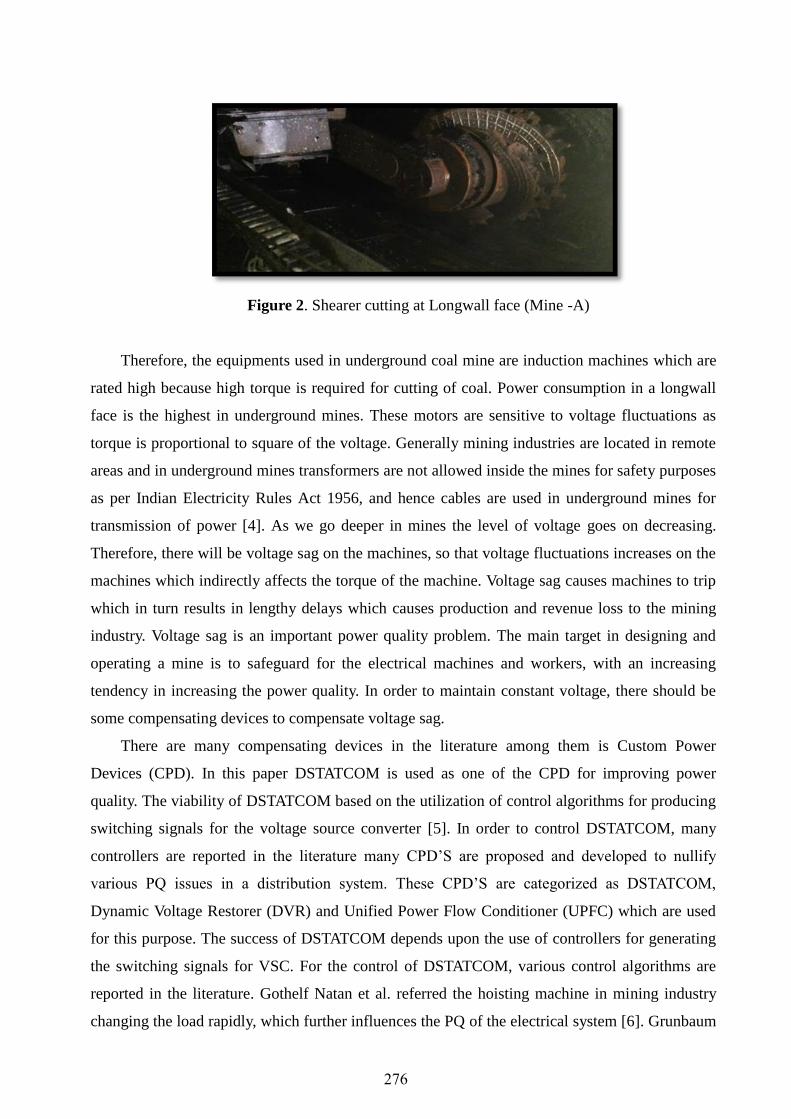
Figure 2. Shearer cutting at Longwall face (Mine -A)
Therefore, the equipments used in underground coal mine are induction machines which are
rated high because high torque is required for cutting of coal. Power consumption in a longwall
face is the highest in underground mines. These motors are sensitive to voltage fluctuations as
torque is proportional to square of the voltage. Generally mining industries are located in remote
areas and in underground mines transformers are not allowed inside the mines for safety purposes
as per Indian Electricity Rules Act 1956, and hence cables are used in underground mines for
transmission of power [4]. As we go deeper in mines the level of voltage goes on decreasing.
Therefore, there will be voltage sag on the machines, so that voltage fluctuations increases on the
machines which indirectly affects the torque of the machine. Voltage sag causes machines to trip
which in turn results in lengthy delays which causes production and revenue loss to the mining
industry. Voltage sag is an important power quality problem. The main target in designing and
operating a mine is to safeguard for the electrical machines and workers, with an increasing
tendency in increasing the power quality. In order to maintain constant voltage, there should be
some compensating devices to compensate voltage sag.
There are many compensating devices in the literature among them is Custom Power
Devices (CPD). In this paper DSTATCOM is used as one of the CPD for improving power
quality. The viability of DSTATCOM based on the utilization of control algorithms for producing
switching signals for the voltage source converter [5]. In order to control DSTATCOM, many
controllers are reported in the literature many CPD’S are proposed and developed to nullify
various PQ issues in a distribution system. These CPD’S are categorized as DSTATCOM,
Dynamic Voltage Restorer (DVR) and Unified Power Flow Conditioner (UPFC) which are used
for this purpose. The success of DSTATCOM depends upon the use of controllers for generating
the switching signals for VSC. For the control of DSTATCOM, various control algorithms are
reported in the literature. Gothelf Natan et al. referred the hoisting machine in mining industry
changing the load rapidly, which further influences the PQ of the electrical system [6]. Grunbaum
276

et al. illustrated about Flexible AC Transmission Systems (FACTS) devices to enhance quality of
supply to mining industry [7]. Parag Nijhawan et al. implemented PI Controller to decrease
harmonic distortion on the distribution network when induction furnace is load as in steel
industry [8]. Bhim Singh et al. presented PI Controller to improve the response and to reduce the
overshoot of the unbalanced load [9,10].
Three controllers are proposed and they are PI controller, Hysteresis Voltage controller and
Fuzzy logic controller. These controllers are implemented in MATLAB/SIMULINK software and
there THD’S are compared.
2. Control of DSTATCOM
Distribution Static Compensator (DSTATCOM) is a voltage source inverter based static
compensator (similar in various respects to the DVR) that is utilized for rectification of voltage
dips. The DSTATCOM is adequate in getting endlessly inductive or capacitive compensation to
its maximum value. The DSTATCOM checks the line waveform with a reference signal, and
consequently, it can give the right measure of lagging or leading reactive compensation to
diminish the voltage variations. The significant parts of a DSTATCOM are a DC capacitor,
inverter module, an AC filter and PWM control strategy [11]. Figure 3 gives the schematics of a
control framework utilizing DSTATCOM. DSTATCOM is regulated by means of Pulse Width
Modulation (PWM) generator. Output of the model is processed with an error detector and it is
fed to a fuzzy logic controller. The output angle ‘δ’ of controller is phase modulated depending on
the controller actions. These signals are provided to PWM generator and the output of the PWM
generator will compensate the voltage sag and improves the performance of DSTATCOM [9].
Figure 3. Control scheme of DSTATCOM
277

3. Controllers
3.1 PI controllers
The main aim of PI controller scheme is to maintain constant voltage magnitude at the point
where a sensitive load is connected, under system disturbances. The control system only
measures the RMS voltage at the load point, i.e., no reactive power measurements are required
[11]. The VSC switching strategy is based on a sinusoidal PWM technique which offers
simplicity and good response. Since custom power is a relatively low-power application, PWM
methods offer a more flexible option than the Fundamental Frequency Switching (FFS) methods
favored in Flexible Alternating Current Transmission System (FACTS) applications. High
switching frequencies can be used to improve on the efficiency of the converter, without
incurring significant switching losses. The controller input is an error signal obtained from the
reference voltage and the RMS value of the terminal voltage measured. Such error is processed
by a PI controller the output is the angle ‘δ’, which is provided to the PWM signal generator. It is
important to note that, in this case, indirectly controlled converter, there is active and reactive
power exchange with the network simultaneously: an error signal is obtained by comparing the
reference voltage with the RMS voltage measured at the load point. The PI controller processes
the error signal and generates the required angle to drive the error to zero, i.e., the load RMS
voltage is brought back to the reference voltage. Figure 4 shows the scheme of PI controller.
Figure 4. Block diagram of PI controller
(1)
(2)
(3)
Output of comparator = Vref -Vrms (4)
where Vref is per unit reference voltage Vrms is voltage in per unit at the load terminals
278

PI controller input is an actuating signal which is the difference between the Vref and Vrms
Output of the controller block the angles. The angle provides to PWM signal generator to obtain
desired firing sequence.
Hysteresis voltage controller
Hysteresis Voltage Controller is utilized to control load voltage and decide exchanging
signals for inverter switches. The control technique applied in this paper is based on voltage error.
It consists of a comparison between the output voltage Vo and the tolerance limits (VH, VL)
around the reference voltage Vref. While the output voltage Vo is between upper limit VH and
lower limit VL, no switching occurs and when the output voltage crosses to pass the upper limit
(lower band) the output voltage is decreased (increased) which is shown in Figure 5. The
hysteresis controller generates the switching pulses that are fed to the VSC. The reference three-
phase voltage signals generated is compared by the three-phase DSTATCOM output voltages to
generate the switching pluses of the IGBTs of the VSC. In hysteresis control, each phase is
regulated independently [12]. The hysteresis band h is the difference between VH and VL (h=VH-
VL). The hysteresis band is inversely proportional to the switching frequency of IGBTs. Figure 6
shows the scheme of Hysteresis voltage controller. The hysteresis voltage control has the
advantage of variable switching frequency, very fast response and simple operation than other
control method. In this method, the following relation is applied where h and fc are Hysteresis
band and switching frequency, respectively.
h= VH-VL (5)
T1 + T2 = Tc =1/fc (6)
Where h is hysteresis band
VH is upper voltage toleranance limit
VL is lower voltage tolerance limit
T1,T2 are time periods of on and off cycles
Respectively
T is the total time period
When Vo > VH, VL is operated (7)
279

Vo < VL , VH is operated (8)
Where Vo is output voltage of the hysteresis band
Figure 5. Principle of Hysteresis voltage controller
Figure 6. Block diagram of Hysteresis voltage controller
The voltages at PCC (Vabc) are converted to the rotating reference frame using the abc-dqo
conversion .Phase Locked Loop, which synchronizes the positive sequence component of the
three phase voltage. The abc_to_dq0 Transformation computes the direct axis (Vd), quadratic axis
(Vq), and zero sequence (Vo) quantities in a two-axis rotating reference frame for a three-phase
sinusoidal signal. Main voltages used as a Phase lock loop (PLL) to generate sine-wave single
phase. The transformation is given below
(9)
(10)
(11)
280
Since the dqo transformation is one that converts frequency dependent signals into ones with
constant value, an ideal three phase system yields constants Vd and Vq. These voltage Vd and Vq
are compared with a reference voltages and these are transformed to dq0 to abc transformation
which is given to Hysteresis voltage controller block which is shown in Figure 46. The
transformation is given below.
(12)
(13)
(14)
where w= rotation speed (rad/s) of the rotating frame.
Fuzzy logic controller
The Fuzzy logic controller is designed to control the load voltage. Controller consists of two
sources such as error (change of supply voltage) and error rate (rate of change of supply voltage)
and output (voltage). Five linguistic factors are choosen. The linguistic factors are Negative Big
(NGB), Negative Medium (NGM), Zero (ZO), Positive Medium (PSM) and Positive Big (PSB).
Triangular membership function is used. Twenty five if then rules are formed. The controller is
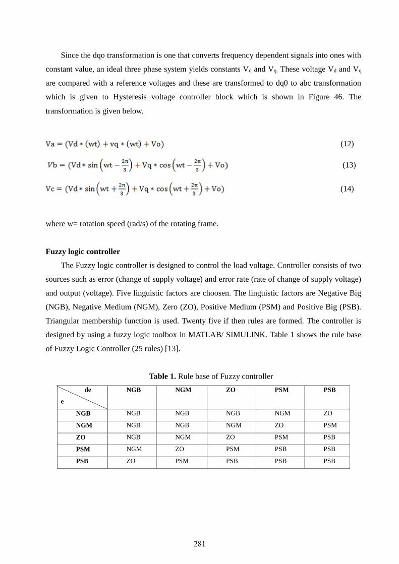
designed by using a fuzzy logic toolbox in MATLAB/ SIMULINK. Table 1 shows the rule base
of Fuzzy Logic Controller (25 rules) [13].
Table 1. Rule base of Fuzzy controller
de
e
NGB NGM ZO PSM PSB
NGB NGB NGB NGB NGM ZO
NGM NGB NGB NGM ZO PSM
ZO NGB NGM ZO PSM PSB
PSM NGM ZO PSM PSB PSB
PSB ZO PSM PSB PSB PSB
281

Figure 7. Rules of Fuzzy logic
Output of the model is processed with an error detector, and it is fed to a fuzzy logic
controller. The output angle ‘δ’ of the controller is phase modulated depending on the controller
actions. These signals in the form of pulses are provided to PWM generator and the output of the
PWM generator will improve the performance of DSTATCOM during a voltage sag. Figure 8
shows the block diagram of the fuzzy logic controller.
Figure 8. Block diagram of Fuzzy logic controller
4. Results and Discussion
Simulation model of a DSTATCOM is developed for a three phase distribution system in
MATLAB environment using SIMULINK and Sim Power System (SPS) toolboxes. The system
voltage is 3.3 kV, 50 Hz and its ratings are shown in Table 2. In order to show the adequacy of
this controller in providing constant voltage, simulations are performed for different types (a)
without a controller and (b) with a controller. Simulation results are examined for different case
282

studies and THD is calculated. For the simulation study a three phase programmable source is
treated as primary distribution substation and the distribution line is treated as the lumped
inductance in series with the resistance. A heavy inductive load is connected at required instants
to study the performance of the DSTATCOM for the case of voltage sag conditions.
Table 2. Mine A Electrical Ratings
S. No Name of the Equipment Rating
Power Voltage Current
1 Transformer (TS2) 4.5 MVA 11 kV / 3.3 kV 236 A / 787.2 A
2 Shearer 855 kW 3.3 kV 2000 A
3
Armoured Face
Conveyor (AFC)
860 kW 3.3 kV 2000 A
4 Beam stage loader(BSL) 400 kW 3.3 kV 2000 A
Without controller
In this section test system is first simulated without DSTATCOM in order to show the
voltage sag problem. Voltage sag is observed in the system by connecting breaker to loads for
certain time period. In this case, three loads are connected to the system from 0.05 s to 0.15 s,
0.20 s to 0.30 s and 0.35 s to 0.45 s which is shown in Table 3. A voltage sag occurs and there is
no control over the system. Before compensation THD observed is 27% which is shown in Table
3 and simulation results are shown in Figure 9. We can observe from the load voltage output that,
there are harmonics present in the system which are harmful to the system. In order to reduce sag
and harmonics, we need to use controllers, these controllers are discussed in the next section. The
load voltage magnitude observed is 0.55 pu.
0 0.05 0.10 0.15 0.20 0.25 0.30 0.35 0.40 0.45 0.500
0.2
0.4
0.6
0.8
1
Time (sec)
Vo
lta
ge
(p
u)
Load Voltage Magnitude
(a) Three phase load voltage magnitude
283

0 0.05 0.10 0.15 0.20 0.25 0.30 0.35 0.40 0.45 0.50
-1
-0.5
0
0.5
1
Time (sec)
Vo
ltag
e (
pu
)
Load Voltage
(b) Three phase voltage
Figure 9. Simulation results without controller
a. With controller
In this section, test system is simulated by employing DSTATCOM controlled by using three
controllers such as PI controller,hysteresis voltage controller and fuzzy logic controller
respectively.
i. PI controller
PI controller is used as a controller in the system and simulation results are shown in Fig.10
(a) three phase load voltage magnitude and (b) three phase load voltage. We can observe from the
results that before compensation THD was 27% whereas after compensation THD reduced to
13.33 % which is shown in Table 3, but complete compensation is not achieved still there is
voltage sag and harmonics present in the system which is undesirable. Therefore due to the
present of voltage sag in the system reactive power compensation achieved is not satisfactorily.
The load voltage magnitude observed from the results is 0.96 pu.
0 0.05 0.10 0.15 0.20 0.25 0.30 0.35 0.40 0.45 0.500
0.2
0.4
0.6
0.8
1
Time (sec)
Vo
ltag
e (
pu
)
Load Voltage Magnitude
(a) Three phase load voltage magnitude
0 0.05 0.10 0.15 0.20 0.25 0.30 0.35 0.40 0.45 0.50
-1
-0.5
0
0.5
1
Time (sec)
Vol
tage
(pu)
Load Voltage
(b) Three phase voltage
Figure 10. Simulation Results with PI controller
284

Hysteresis voltage controller
When this hysteresis voltage controller is introduced results show that THD is reduced to
5.37 % when compared to THD of PI controller which is given in Table 3 and simulation results
are shown in Fig.11 (a) three phase load voltage magnitude and (b) three phase load voltage. We
can observe from the results that hysteresis voltage controller is better than PI controller, but still
there are harmonics present in the system. In this case reactive power compensation is found to
be satisfactory when compared with PI controller. The load voltage magnitude observed from the
results is 0.98 pu.
0 0.05 0.10 0.15 0.20 0.25 0.30 0.35 0.40 0.45 0.500
0.2
0.4
0.6
0.8
1
Time (sec)
Vol
tage
(pu)
Load Voltage Magnitude
(a) Three phase load voltage magnitude
0 0.05 0.10 0.15 0.20 0.25 0.30 0.35 0.40 0.45 0.50
-1
-0.5
0
0.5
1
Time (sec)
Vol
tage
(pu)
Load Voltage
(b) Three phase load voltage
Figure 11. Simulation Results with Hysteresis voltage controller
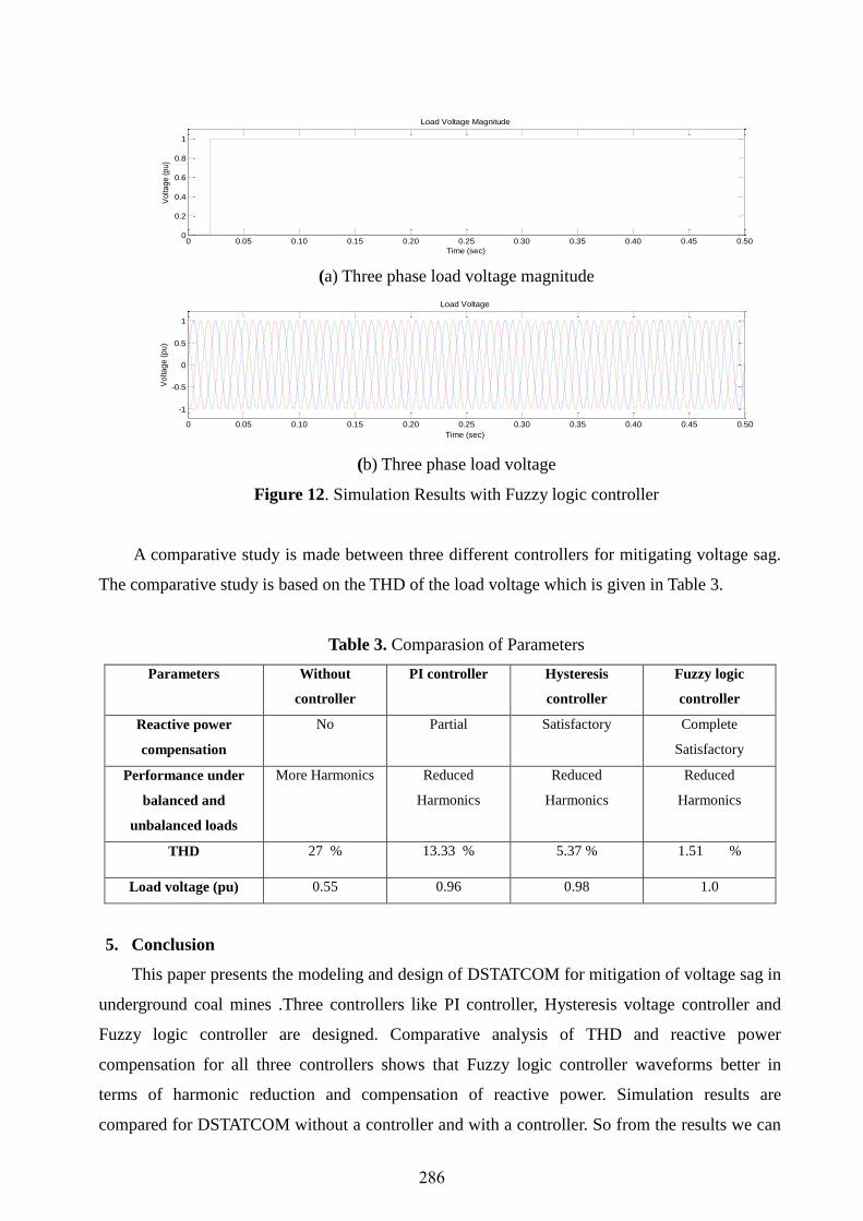
Fuzzy logic controller
In this section, Fuzzy logic controller based DSTATCOM is introduced and results show
that, THD is decreased to 1.51 % which is given in Table 3. Results are shown in Figure 12 (a)
three phase load voltage magnitude and (b) three phase load voltage. We can observe from the
results that mitigation of voltage sag compensation is achieved by using Fuzzy logic controller
when compared with other two controllers. Fuzzy Logic Control based DSTATCOM is used to
compensate reactive power and harmonics. The load voltage magnitude observed from the results
is 1.0pu. The Fuzzy Logic Controller based DSTATCOM demonstrates a better
dynamicbehaviour than conventional methods.
285
0 0.05 0.10 0.15 0.20 0.25 0.30 0.35 0.40 0.45 0.500
0.2
0.4
0.6
0.8
1
Time (sec)
Vo
ltag
e (
pu
)
Load Voltage Magnitude
(a) Three phase load voltage magnitude
0 0.05 0.10 0.15 0.20 0.25 0.30 0.35 0.40 0.45 0.50
-1
-0.5
0
0.5
1
Time (sec)
Vo
lta
ge
(p
u)
Load Voltage
(b) Three phase load voltage
Figure 12. Simulation Results with Fuzzy logic controller
A comparative study is made between three different controllers for mitigating voltage sag.
The comparative study is based on the THD of the load voltage which is given in Table 3.
Table 3. Comparasion of Parameters
Parameters Without
controller
PI controller Hysteresis
controller
Fuzzy logic
controller
Reactive power
compensation
No Partial Satisfactory Complete
Satisfactory
Performance under
balanced and
unbalanced loads
More Harmonics Reduced
Harmonics
Reduced
Harmonics
Reduced
Harmonics
THD 27 % 13.33 % 5.37 % 1.51 %
Load voltage (pu) 0.55 0.96 0.98 1.0
5. Conclusion
This paper presents the modeling and design of DSTATCOM for mitigation of voltage sag in
underground coal mines .Three controllers like PI controller, Hysteresis voltage controller and
Fuzzy logic controller are designed. Comparative analysis of THD and reactive power
compensation for all three controllers shows that Fuzzy logic controller waveforms better in
terms of harmonic reduction and compensation of reactive power. Simulation results are
compared for DSTATCOM without a controller and with a controller. So from the results we can
286

observe that voltage dip problem is mitigated as we compared with and without controller. It is
observed that Fuzzy logic controller load voltage magnitude is 0.99 pu which is better than the
use of other controllers in the system. It is clear from the above simulation studies that Fuzzy
logic controller is more efficient in mitigating the voltage sag problem and also reactive power
compensation is found to be satisfactory. The THD measured in the presence of a Fuzzy logic
controller with DSTATCOM is within the IEEE standards. Maintaining constant voltage level
results in higher productivity of the coal and also reliable and safety operation to the equipment
connected to the supply system.
References
1. G. Einicke, J. Ralston, C. Hargrave, D. Reid, D. Hainsworth, Longwall mining automation an
application of minimum-variance smoothing, 2008, IEEE Control Systems, vol. 28, no.6.
2. G.W. Mitchell, Longwall mining, Australian coal mining practice, pp. 340-373, 2009.
3. A. M. Lloyd, Mine power systems. Bureau of Mines, United States Department of the
Interior, Minerals Health and Safety Technology, vol. 2, 1981.
4. L.C. Kaku, A study of Indian electricity rules, 1956, Lovely Prakashan publishers, Dhanbad.
India.
5. A. Ghosh, G. Ledwich, Power quality enhancement using custom power devices, Springer
Science & Business Media, 2012.
6. N. Gothelf, L. Mukka, C. Payerl. Dynamic var compensation of mine hoists for improvement
of power quality and increase of productivity at LKAB Sweden. In Electricity Distribution-
Part 1, CIRED, 20th International Conference and Exhibition on, pp. 1-4. IET, 2009.
7. R. Grünbaum, J. Rasmussen. FACTS for cost-effective improvement of power feeding of
large mining complexes. In IECON 2012-38th Annual Conference on IEEE Industrial
Electronics Society, pp. 1295-1300, IEEE, 2012.
8. P. Nijhawan, R.S. Bhatia, D.K. Jain. Application of PI controller based DSTATCOM for
improving the power quality in a power system network with induction furnace
load. Sonklanakarin Journal of Science and Technology, vol .34, no. 2, 195, 2012.
9. B. Singh, S.R. Arya. Design and control of a DSTATCOM for power quality improvement
using cross correlation function approach. International Journal of Engineering, Science and
Technology, Vol. 4, no. 1, 74-86, 2012.
10. B. Singh, S. K. Dube, S. R. Arya, An improved control algorithm of DSTATCOM for power
quality improvement.2008, International Journal of Electrical Power & Energy Systems, pp.
493-504.
287
11. D. Masand, S. Jain, G. Agnihotri, Control algorithms for Distribution Static Compensator
DSTATCOM, 2006 In IEEE International Symposium on Industrial Electronics, Vol. 3, pp.
1830-1834.
12. F.A. Jowder, Modeling and simulation of Dynamic Voltage Restorer (DVR) based on
hysteresis voltage control, 2007, 33rd Annual Conference of the IEEE Industrial Electronics
Society, pp. 1726-1731.
13. T.J. Ross, Fuzzy logic with engineering applications, John Wiley & Sons, 2009.
288