Embed Size (px)
Citation preview

IM_ONE-04www.ueonline.com 1
One Series Electronic Pressureand Temperature Switches
Discrete Input and Loop-Powered Models: 2W2D, 2W4D, 2W3A, 2WLPExternal PoweredModels: 4W3A, 8W2D
UNITED ELECTR IC CONTROLS
Installation and Maintenance Instructions
IM_ONE-04
Please read all instructional literature carefully and thoroughly before starting. Refer to the final page for the listing of Recommended Practices, Liabilities and Warranties.
GENERAL (MOUNTING and WIRING) MISUSE OF THIS PRODUCT MAY CAUSE EXPLOSION AND PERSONAL INJURY. THESE INSTRUCTIONS MUST BE THOROUGHLY READ AND UNDERSTOOD BEFORE UNIT IS INSTALLED.
WARNING: EXPLOSION HAZARD - SUBSTITUTION OF COMPONENTS MAY IMPAIR SUITABILITY FOR USE IN HAZARDOUS LOCATIONS.
WARNING: SEE THE PRODUCT NAMEPLATE INFORMATION FOR SPECIFIC AGENCY CERTIFICATIONS APPLICABLE TO YOUR PRODUCT.
2W2D MODELSTHIS EQUIPMENT IS SUITABLE FOR USE IN CLASS I, DIVISION 2, GROUPS A, B, C AND D; CLASS II, DIVISION 2, GROUPS F AND G; CLASS III; CLASS I, ZONE 2 AEx nC IIC T5; CLASS I, ZONE 2 Ex nC IIC T5; OR CLASS I, DIVISION 1, GROUPS A, B, C AND D; CLASS II, DIVISION 1, GROUPS E, F AND G; CLASS III; CLASS I, ZONE 0 AEx ia IIC T5; CLASS I, ZONE 0 Ex ia IIC T5; WHEN INSTALLED PER DRAWING #A-62174-19 (NORTH AMERICA); OR NON-HAZARDOUS LOCATIONS ONLY.
THIS EQUIPMENT IS ATEX CERTIFIED SUITABLE FOR APPROPRIATE USE IN GAS ZONE 2 & DUST ZONE 22 APPLICATIONS OR GAS ZONE 0 & DUST ZONE 20 APPLICATIONS WHEN INSTALLED PER DRAWING #A-62174-20 (EUROPE). II 1 G EEx ia IIC T5 II 3 G EEx nL IIC T5
II 1 D T+ 90ºC II 3 D T+ 90ºC -40ºC TAMB. +60ºC, IP66 -40ºC TAMB. +60ºC, IP66 Cert. No. DEMKO 03 ATEX 0322281X Cert. No. DEMKO 03 ATEX 0322281X
2W4D MODELSTHERE ARE CURRENTLY NO AGENCY APPROVALS AVAILABLE FOR THE 48 VDC VERSION OF THE ONE SERIES, MODEL 2W4D. PLEASE CHECK WITH UE TECHNICAL SALES FOR THE LATEST INFORMATION REGARDING THE ONE SERIES.
2W3A MODELSTHIS EQUIPMENT IS SUITABLE FOR USE IN CLASS I, DIVISION 2, GROUPS A, B, C AND D; CLASS II, DIVISION 2, GROUPS F AND G; CLASS III; CLASS I, ZONE 2 AEx nC IIC T5; CLASS I, ZONE 2 Ex nC IIC T5; OR NON-HAZARDOUS LOCATIONS ONLY.
THIS EQUIPMENT IS ATEX CERTIFIED SUITABLE FOR APPROPRIATE USE IN GAS ZONE 2 & DUST ZONE 22 APPLICATIONS. II 3 G Ex nL IIC T5 II 3 D T+ 90ºC
-40ºC ≤ TAMB. ≤ +60ºC, IP66 Cert. No. DEMKO 08 ATEX 0726838X
2WLP AND 8W2D MODELS THIS EQUIPMENT IS SUITABLE FOR USE IN CLASS I, DIVISION 2, GROUPS A, B, C AND D; CLASS II, DIVISION 2, GROUPS F AND G; CLASS III; CLASS I, ZONE 2 AEx nC IIC T4 CLASS I, ZONE 2 Ex nC IIC T4; OR NON-HAZARDOUS LOCATIONS ONLY.
THIS EQUIPMENT IS ATEX CERTIFIED SUITABLE FOR APPROPRIATE USE IN GAS ZONE 2 & DUST ZONE 22 APPLICATIONS. II 3 G Ex nL IIC T4 II 3 D T+ 110ºC
-40ºC ≤ TAMB. ≤ +60ºC, IP66 Cert. No. DEMKO 08 ATEX 0726838X
0539

IM_ONE-04www.ueonline.com2
4W3A MODELSTHIS EQUIPMENT IS SUITABLE FOR USE IN CLASS I, DIVISION 2, GROUPS A, B, C AND D; CLASS II, DIVISION 2, GROUPS F AND G; CLASS III; CLASS I, ZONE 2 AEx nC IIC T4; CLASS I, ZONE 2 Ex nC IIC T4; OR NON-HAZARDOUS LOCATIONS ONLY.
MOUNTINGTools Required1-1/16" wrench for sensor hex fittingScrewdriver for mounting bolts2 mounting bolts (1/4" Max.)
BEFORE INSTALLING, CHECK THE SENSOR MODEL SELECTED FOR COMPATIBILITY TO THE PROCESS MEDIA IN CONTACT WITH THE SENSOR AND WETTED PARTS.
Electronics HousingMount the unit using the two (2) 1/4” clearance holes in the mounting ears. Plumb sensor to the process port. See page 22 for dimensions.The One Series product may be mounted in any position except with the electrical conduit connection facing up. Ensure the process connection is sealed to the process port to prevent leakage. Care should be taken to minimize effects of shock and vibration.NOTE: optimal display viewing angle/position - 6:00
FOR PRESSURE AND LOCAL TEMPERATURE MODELS ALWAYS HOLD A WRENCH ON THE SENSOR HEX WHEN MOUNTING UNIT. DO NOT TIGHTEN BY TURNING ENCLOSURE, THIS WILL DAMAGE THE CONNECTION BETWEEN THE SENSOR AND HOUSING.
INSTALL UNITS WHERE SHOCK, VIBRATION AND TEMPERATURE FLUCTUATIONS ARE MINIMAL. ORIENT UNIT TO PREVENT MOISTURE FROM ENTERING ENCLOSURE. USE PROPERLY RATED SEALING FITTINGS FOR ELECTRICAL WIRE ENTRY. DO NOT MOUNT UNIT IN AMBIENT TEMPERATURES EXCEEDING PUBLISHED LIMITS. THIS IS ESPECIALLY CRITICAL FOR LOCAL MOUNT TEMPERATURE UNITS.
IN HIGH SHOCK AND VIBRATION APPLICATIONS, SECURE THE ENCLOSURE AS DETAILED BELOW. DO NOT MOUNT VIA THE PROCESS CONNECTION ONLY.
FOR DIFFERENTIAL PRESSURE MODELS (ESPECIALLY LOW RANGE UNITS), CARE SHOULD BE TAKEN TO MOUNT THE SENSOR LEVEL TO MINIMIZE ANY PRESSURE READING OFFSETS. THE OFFSET COMMAND MAY BE USED TO ZERO THE DISPLAY, SEE PAGE 13 FOR ADDITIONAL INFORMATION.
Process Connections and Sensor InstallationPressure and Differential Pressure ModelsTo pipe mount: Thread the pressure connection onto the pressure port, making sure that the mating threads are clean and free of debris. Use a wrench on the hex pressure connection to tighten. Test for leaks. On Differential Pressure models, the Low (L) side pressure must NOT exceed the high (H) side pressure.
WARNING: NEVER INSERT ANY OBJECT INTO THE PRESSURE SENSOR OPENING. DAMAGE TO THE SENSOR WILL RESULT, AFFECTING ACCURACY.
Local and Remote Temperature ModelsFor Remote Sensing (models C, H & R): Route the extension wire to avoid contact with live components. Avoid kinks, or excessive flexing.
For Surface Sensing (models C, H & R): Secure the sensor housing to the pipe or vessel using an adhesive or strapping method suitable for the application.
For Immersion Sensing (models C, H, R & L): Use of a thermowell is highly recommended to aid in maintenance, testing and preservation of the system integrity. Insert the sensor housing (0.25" diameter) into the well ensuring that the housing bottoms out and will be completely immersed in the media (2.5" min.) Secure the sensor using an appropriately sized compression fitting or union connector. Refer to options W073, W074 and W080 in the bulletin One Series-B.
For Local Ambient Sensing (model L): Mount using the mounting ears on the electronics housing. Mount the product to ensure that the sensor housing will not be damaged and where the measured temperature is representative of the surrounding environment.
For best temperature measurements, the sensor housing must be in full contact with the surface or media being measured. Heat transfer compound may be used to aid in fully transferring the media temperature to the sensor housing. Locate where the temperature is most representative of the system. Minimum insertion depth is 2-1/2".

IM_ONE-04www.ueonline.com 3
CLEANING THE FACEPLATEOne Series models with ATEX approvals have a urethane based conductive coating applied to the faceplate perimeter. The cleaning of this surface should be performed with a damp cloth only. Should the surface exhibit signs of flaking or wear, the product should be removed from service in hazardous locations where ATEX approvals are required.
WIRING Tools RequiredPhillips-head screwdriverSmall flat-head screwdriver Wire strippers
WARNING: EXPLOSION HAZARD - DO NOT REPLACE COMPONENTS UNLESS POWER HAS BEEN SWITCHED OFF OR THE AREA IS KNOWN TO BE NON-HAZARDOUS.
WARNING: EXPLOSION HAZARD - DO NOT DISCONNECT EQUIPMENT UNLESS POWER HAS BEEN SWITCHED OFF OR THE AREA IS KNOWN TO BE NON-HAZARDOUS
TO MAINTAIN ENCLOSURE INTEGRITY FRONT DISPLAY SCREWS ARE TO BE TORQUED AT 4 IN-LBS (0.45 N-m) IN END USE APPLICATION.
THE DEVICES SHALL BE PROPERLY GROUNDED IN THE END USE APPLICATION.
LEADWIRES MUST BE RATED 75°C MINIMUM COPPER CONDUCTOR ONLY.
MODEL 2W2D ACCEPTS 12-30 VDC AS ITS POWER SOURCE, DIRECTLY FROM DIGITAL INPUTS TO PLCs, DCSs AND OTHER LOW-POWER DC LOADS. THE SWITCHED OUTPUT MAXIMUM LOAD RATING IS 40 mA. THE UNIT MUST NOT BE CONNECTED DIRECTLY TO A POWER SUP-PLY WITHOUT AN APPROPRIATE CURRENT LIMITING LOAD SUCH AS THAT PROVIDED BY A PLC/DCS DISCRETE INPUT. OvERLOADING THE SWITCH MAy CAUSE FAILURE. FOR INTRINSICALLY-SAFE INSTALLATIONS, PLEASE REFERENCE THE CONTROL DRAWINGS (UE 62174-19 NORTH AMERICA OR 62174-20 EUROPE) FOR INTRINSIC SAFETY ENTITY PARAMETERS AND OTHER NECESSARY INFORMATION. MODEL 2W2D MUST BE WIRED TO AN APPROVED I.S. BARRIER. REFER TO PAGE 17 FOR ADDITIONAL INFORMATION ON SELECTING AN INTRINSIC SAFETY BARRIER. SUBSTITUTION OF COMPONENTS MAY IMPAIR INTRINSIC SAFETY.
MODEL 2W4D ACCEPTS 30-50 VDC AS ITS POWER SOURCE, DIRECTLY FROM DIGITAL INPUTS TO PLCs, DCSs AND OTHER LOW-POWER DC LOADS. THE SWITCHED OUTPUT MAXIMUM LOAD RATING IS 40 mA. THE UNIT MUST NOT BE CONNECTED DIRECTLY TO A POWER SUPPLY WITHOUT AN APPROPRIATE CURRENT LIMITING LOAD SUCH AS THAT PROVIDED BY A PLC/DCS DISCRETE INPUT. OvERLOADING
THE SWITCH MAy CAUSE FAILURE.
MODEL 2W3A ACCEPTS 90-130 VAC/VDC AS ITS POWER SOURCE, DIRECTLY FROM DISCRETE INPUTS TO PLCs, DCSs AND OTHER LOW-POWER LOADS. THE SWITCHED OUTPUT MAXIMUM LOAD RATING IS 100 mA. THE UNIT MUST NOT BE CONNECTED DIRECTLY TO A POWER SUPPLY WITHOUT AN APPROPRIATE CURRENT LIMITING LOAD SUCH AS THAT PROVIDED BY A PLC/DCS DISCRETE INPUT. OvERLOADING
THE SWITCH MAy CAUSE FAILURE.
MODEL 2WLP IS LOOP-POWERED AND OBTAINS POWER FROM THE 4-20 mA LOOP. THE 2WLP41 SWITCHED OUTPUT MAXIMUM LOAD RATING IS 0.6 A @ 140 VDC OR VAC AND 0.3 A @ 280 VDC OR VAC FOR MODEL 2WLP43. OVERLOADING THE SWITCH MAY CAUSE FAILURE. THE SWITCH MUST NOT BE CONNECTED DIRECTLy TO A POWER SUPPLy.
MODEL 4W3A ACCEPTS 90-130 VAC AS ITS POWER SOURCE. THE SWITCHED OUTPUT MAXIMUM LOAD RATING IS 10 A, 24-280 VAC AT T(amb) 38°C (100°F). DERATE 1.9 A/10°C (18°F). OvERLOADING THE SWITCH MAy CAUSE FAILURE.
MODEL 8W2D ACCEPTS 12-30 VDC AS ITS POWER SOURCE. THE MAXIMUM LOAD RATING FOR EACH SWITCH IS SHOWN IN THE TABLE ON PAGE 5. OvERLOADING THE SWITCH MAy CAUSE FAILURE.
Remove the four (4) Phillips-head screws holding the faceplate to the enclosure. Gently remove the faceplate module. Exercise caution so that the wires going between the sensor and the faceplate module are not damaged or removed. Locate field wires and strip carefully. Insert field wiring per the diagrams on page 4. Carefully place the faceplate back on the enclosure and re-attach using the (4) Phillips screws (4 in-lbs or 0.45 N-m). DO NOT OVERTIGHTEN.

IM_ONE-04www.ueonline.com4
Terminal Block and Torque DetailsThe 2W2D and 2W4D terminal block is marked “+” and “-”, and includes a chassis ground symbol. These markings indicate the polarity of this polarized switch. Polarity must be observed or the product will not work, making it necessary to reverse the wiring connections. The 2W2D and 2W4D is reverse polarity protected, so no damage results from miswiring. The product terminal block accepts 14-22 AWG wiring and the recom-mended torque is 7 in-lbs.
The 2W3A terminal block is marked with a switch symbol, and includes a chassis ground symbol. The 2W3A is a non-polarized switch, so connec-tions can be made to either terminal without observing polarity. The 2W3A terminal block accepts 14-22 AWG wiring and the recommended torque is 7 in-lbs.
The 2WLP has two terminal blocks, TB1 and TB2. TB1 has three positions, two marked with a switch symbol and one marked with a chassis ground symbol. TB1 terminal block accepts 14-22 AWG wiring and the recommended torque is 3.48 in-lbs. TB2 has two positions marked “4-20+” and 4-20-”. These markings indicate the polarity of the 4-20 mA analog signal. Polarity must be observed. TB2 terminal block accepts 14-26 AWG wiring and the recommended torque is 4.38 in-lbs.
The 4W3A has one terminal block labeled TB1. TB1 has four positions, marked with “L1”, “L2” and a switch symbol covering the remaining two positions. TB1 terminal block accepts 14-22 AWG wiring and the recommended torque is 5 in-lbs.
The 8W2D has three terminal blocks, one located on the back of the display module and two, labeled TB1 and TB2, located on circuit board per-manently mounted inside the enclosure. The display module terminal block accepts 14-22 AWG wiring and the recommended torque is 7 in-lbs. TB1 has two positions marked “4-20+” and 4-20-”. These markings indicate the polarity of the 4-20 mA analog signal. Polarity must be observed. TB1 terminal block accepts 14-26 AWG wiring and the recommended torque is 4.38 in-lbs. TB2 has five positions, four marked with a switch symbol and one marked with a chassis ground symbol. TB2 terminal block accepts 14-22 AWG wiring and the recommended torque is 3.48 in-lbs.
NOTE: The sensor wiring harness must be connected to the module with the red wire oriented to the arrow on the label. Reversing this connector will result in measurement errors or failure.

IM_ONE-04www.ueonline.com 5
Model 2W2D/2W4D is intended for direct connection to a PLC or DCS discrete input, or other suitable load (see page 16). Power is obtained and the discrete switch signal is provided by the same two-wire connection. Polarity must be observed. Refer to the Switch Ratings Table for the switch ratings. Do not connect model 2W2D or 2W4D directly to a power supply without a suitable load in series with the switch.
These circuit diagrams provide a rear view of the display module after it has been removed from the base enclosure.
Figures 1, 2 and 4 show typical wiring schemes depicting model 2W2D/2W4D connected to a programmable logic controller (PLC), distributed control system (DCS) or other logic solver discrete input. The circuits shown inside a dotted line box next to the display module are part of the discrete input and are not required to complete the wiring.
NOTE: For bench testing model 2W2D/2W4D, a circuit is required as shown in Figure 3. These components are not included and must be provided by the tester. Do not connect model 2W2D/2W4D directly to a power supply without a suitable load in series with the switch.
Model 2W2D/2W4D can also be wired in series with the coil of certain interposing relays, as shown in Figure 5. The relay coil specifications must not exceed the maximum switch ratings of model 2W2D/2W4D.
NOTE: Model 2W2D has a maximum switch rating of 30 VDC @ 40 mA and model 2W4D has a maximum switch rating of 50 VDC @ 40 mA. Do not exceed this rating or permanent damage may result.
WIRING DIAGRAMS - MODEL 2W2D/2W4D(Use Class 2 or SELv Power Supply Only)
2W2D (12-30 VDC)2W4D (30-50 VDC)
2W2D (12-30 VDC)2W4D (30-50 VDC)
2W2D (12-30 VDC)2W4D (30-50 VDC)
2W2D (12-30 VDC)2W4D (30-50 VDC)
2W2D (12-30 VDC)2W4D (30-50 VDC)
MODEL 2W2D/2W4D
MODEL 2W2D/2W4D
MODEL 2W2D/2W4D
MODEL 2W2D/2W4D
MODEL 2W2D
FIGURE 4
FIGURE 3
FIGURE 2
FIGURE 1
FIGURE 5

IM_ONE-04www.ueonline.com6
Model 2W3A is intended for direct connection to a 115 VAC PLC or DCS discrete input, or other suitable load (see page 16). Power is obtained and the discrete switch signal is provided by the same two-wire connection. Model 2W3A is a non-polarized switch and may be used in VDC circuits. Refer to the Switch Ratings Table for the switch ratings. Do not connect model 2W3A directly to a power supply without a suitable load in series with the switch.
These circuit diagrams provide a rear view of the display module after it has been removed from the base enclosure.
Figure 1 shows a typical wiring scheme for when model 2W3A is connected to a programmable logic controller (PLC), distributed control system (DCS) or other logic solver discrete input. The circuit shown inside the dotted line box next to the display module is part of the discrete input and is not required to complete the wiring.
NOTE: For bench testing model 2W3A, a suitable load resistor is required and included as shown in Figure 2. Do not connect model 2W3A directly to a power supply without a suitable load in series with the switch.
Model 2W3A can also be wired in series with the coil of certain interposing relays, as shown in Figure 3. The relay coil specifications must not exceed the maximum switch ratings of model 2W3A.
NOTE: Model 2W3A has a maximum switch rating of 130 VAC and VDC @ 100 mA. Do not exceed this rating or permanent damage to the One Series may result.
WIRING DIAGRAMS - MODEL 2W3A
MODEL 2W3ADISCRETE INPUT
WIRING
FIGURE 1
MODEL 2W3ABENCH TESTSCHEMATIC
FIGURE 2
FIGURE 3
MODEL 2W3AWITH EXTERNAL
RELAY
IM_ONE-04www.ueonline.com 7
Model 2WLP is loop-powered and is connected directly to an analog input of a PLC or DCS via TB2 providing a 4-20 mA analog signal. Polarity must be observed. The loop connection powers the entire One Series, including the solid-state relay switch actuation. The auxiliary solid-state relay is connected via TB1 and is intended to switch an external load. These circuit diagrams provide a rear view of the display module after it has been removed from the base enclosure.
This model comes with two open conduits, one intended for power wiring and the other intended for signal wiring.
Figure 1 shows a typical wiring scheme for when model 2WLP is connected to a programmable logic controller (PLC), distributed control system (DCS) or other logic solver analog input that provides loop power. The circuit shown inside the dotted line box next to the display module is part of the analog input and is not required to complete the wiring.
For model 2WLP, Figure 2 shows an external power supply used to provide loop power and switched load power using an internal jumper to simplify wiring. In this application, both an analog and a discrete (switched) signal is connected to the PLC.
Model 2WLP can also be wired in series with the coil of certain interposing relays. The relay coil specifications must not exceed the maximum switch ratings of the 2WLP model chosen. Refer to the Switch Ratings Table for the solid-state relay switch ratings.
As an alternative to loop power, Figure 3 shows model 2WLP wired directly to a power supply. This wiring scheme provides power for all model 2WLP functions, but a 4-20 mA output is not possible.
NOTE: Do not exceed the maximum switch ratings or permanent damage to the One Series may result.
MODEL 2WLPLOOP POWERED
INPUT WIRING
FIGURE 1
FIGURE 2
FIGURE 3
MODEL 2WLPANALOG & DISCRETE
INPUT WIRING WITH
COMMON POWER SUPPLY
MODEL 2WLP43WITH
24 VDC POWER SUPPLY(NO 4-20 mA)
WIRING DIAGRAMS - MODEL 2WLP

IM_ONE-04www.ueonline.com8
Model 4W3A requires a 90-130 VAC @ 15 mA external power supply. Power for all functions is provided from the power supply connection to TB2 C (L1) and D (L2) termi-nals. Connections to the solid-state relay are also made at TB1.
No user wiring connections to the display module are required for model 4W3A.
Figure 1 shows a typical 3-wire wiring scheme for model 4W3A where only three wires are required. This assumes that the One Series power supply and the load power supply are the same (common). An internal jumper is required for this wiring scheme, as shown on TB1.
Figure 2 shows a typical 4-wire wiring scheme for model 4W3A. One power supply is used for instrument power and a separate (isolated) power supply is used for the load. No jumper is required for this 4-wire configuration.
NOTE: The solid-state relay used in model 4W3A has a minimum load requirement of 150 mA, making it incom-patible with logic solver discrete inputs. For these types of inputs, choose another One Series model.
NOTE: Do not exceed the maximum switch ratings or per-manent damage to the One Series may result.
WIRING DIAGRAMS - MODEL 4W3A
L1
L2
Load
(Line)
(Neutral)
90-130 VAC@ 10 A
(Neutral)
90-130 VAC
MODEL 4W3A3-WIRE WIRING
MODEL 4W3A4-WIRE WIRING
L1
L2
Load
(Line)
(Neutral)
24-240 VAC@ 10 A
24-240 VAC
90-130 VAC
TB1
TB1
FIGURE 1
FIGURE 2

IM_ONE-04www.ueonline.com 9
Model 8W2D requires a 12-30 VDC @ 30 mA external power supply and includes two solid-state relays and a 4-20 mA output. All of these components are electrically isolated and can be wired independently, requiring 8 con-nections.
Figures 1 & 2 show the various wiring terminal blocks as they appear on the display module (rear) and inside the base enclosure. The sensor cable and the 8-conductor ribbon cable must remain connected to the display mod-ule.
This model includes two open conduits, one intended for power wiring and the other intended for signal wiring.
Power Supply: Connect the leads from an external power supply to the + and – terminals of TB1 on the back of the display module, observing polarity.(Use Class 2 or SELV power supply only)
Solid-state relays: Connect the two solid-state relays at TB2 to appropriate loads. See Figure 2. Do not exceed the maximum switch ratings or permanent damage to the One Series may result. Use of the solid-state relays is optional.
Analog output: Connect the 4-20 mA output leads at TB1 of the relay board using the + and – terminals. The analog output can be wired for a sinking or sourcing 4-20 mA output. The 4-20 mA output in model 8X2D is not self-powered. 24 VDC must be provided. This can be accomplished by using a jumper between TB1 + terminal of the display module and TB1 + terminal of relay board. The analog output is then available at TB1 – terminal. Use a separate power supply if isolation from the main supply is desired. Use of the analog output is optional.
NOTE: For model 8X2D45, providing a jumper between TB1 + terminal, + 4-20 mA and SW1 and SW2 allows the use of a single (common) power supply for all loads and the 4-20 mA output. This will greatly simplify wiring, assuming both switch loads are 24 VDC.
NOTE: The solid-state relays used in model 8X2D42 and SW1 in model 8W2D44 have a minimum load requirement of 50 mA, making it incompatible with logic solver discrete inputs. For these types of inputs, choose another One Series model.
NOTE: Do not exceed the maximum switch ratings or permanent damage to the One Series may result.
WIRING DIAGRAMS - MODEL 8W2D
Ribbon Cable
Ribbon Cable
DISPLAY MODULE(REAR)
- 4-20 mA
+ 4-20 mA
SW2
SW1
TB1
TB2
RELAY BOARD INBASE ENCLOSURE
FIGURE 1
FIGURE 2

IM_ONE-04www.ueonline.com10
Switch Ratings TableModel Number SW1 SW22W2D00 12-30 VDC @ 40 mA N/A
2W4D00 30-50 VDC @ 40mA N/A
2W3A00 90-130 VAC/VDC @ 100 mA N/A
2WLP41 0-140 VAC/VDC @ 0.6 A 1 N/A
2WLP43 0-280 VAC/VDC @ 0.3 A 1 N/A
4W3A01 24-280 VAC @ 10 A 2 N/A
8W2D42 75-250 VAC @ 1.5 A 3 75-250 VAC @ 1.5 A 3
8W2D44 75-250 VAC @ 1.5 A 3 0-140 VAC/VDC @ 0.6 A 1
8W2D45 0-140 VAC/VDC @ 0.6 A 1 0-140 VAC/VDC @ 0.6 A 1
Warning: Exceeding the current or voltage ratings could damage the One Series
THEORy OF OPERATIONThe One Series electronic switch product line is based on an all-solid-state electronic module that incorporates a microprocessor. The combination of features like no moving parts and IAW self-diagnostics provide a highly reliable, accurate and repeatable monitor for detecting pressure and temperature thresholds and, once reached, can make intelligent switch decisions based on retained settings and current conditions. Where a mechanical device has no way of determining its “readiness”, the One Series monitors its own health and reports it locally. This IAW (I Am Working) feature provides a solution to the “blind device” issue common with mechanical apparatus. You will always know the health status of the One Series.
The One Series is also very rugged, featuring a Type 4X, weather-tight enclosure suitable for harsh environments and hazardous (Class I, Division 2) locations. The 0.5% accuracy rating is maintained over a very wide -40°C - (+70°C) operating range using active tempera-ture compensation. Repeatability rivals that of a process transmitter, with a 0.1% of full range rating. The set point and deadband (hys-teresis) of the switch is fully programmable over the entire range of the sensor. Reaction time for the One Series to a process change is typically 60 mS or less.
2-WIRE SIMPLICITy (2W Models only)The One Series 2-Wire electronic pressure switch (patented) is designed to operate on discrete input leakage current (models 2W2D, 2W4D and 2W3A) or analog input 4-20 mA loop power (models 2WLP41 and 2WLP43). The microprocessor-based One Series 2-Wire is the only electronic switch to operate and switch over a single pair of wires, similar to a traditional mechanical switch or 4-20 mA process transmitter. It combines the simplicity and low cost features of a switch and the reliability features of a transmitter, at less than half the price of the transmitter, and without the need to pull additional wiring.
• Model 2W2D00 is designed to work with most 24 VDC discrete Programmable Logic Controller (PLC) or Distributed Control System (DCS) inputs and some relays. When open, the switch draws 750 µA; when closed the switch sinks or sources 40 mA maximum @ 12-30 VDC.
• Model 2W4D00 is designed to work with most 48 VDC discrete Programmable Logic Controller (PLC) or Distributed Control System (DCS) inputs and some relays. When open, the switch draws 1 mA; when closed the switch sinks or sources 40 mA maximum @ 30-56 VDC.
• Model 2W3A00 is designed to work with most 115 VAC discrete PLC or DCS inputs and some relays. When open, the switch draws 1 mA; when closed, the switch sinks or sources 100 mA maximum @ 90-130 VAC or VDC.
• Model 2WLP4x is loop-powered and operates in a transmitter loop attached to an analog PLC or DCS input and provides a field-scalable 4-20 mA signal over a 2-wire connection. Model 2WLP41 contains an auxiliary solid-state relay switch rated for 0.6 A @ 140 VAC or VDC maximum and requires 2 additional wires, if used. Model 2WLP43 is rated for 0.3 A @ 280 VAC or VDC.
DISPLAyThe One Series features a large, easy-to-read display, showing the process condition and the status of the instrument. (See Display Features for a complete description.) Set point, deadband and minimum/maximum process values can be easily accessed from the front of the unit while in operation. Programming and interrogating the One Series is done through two buttons on the faceplate. HIGH-POWER AND DUAL SWITCHINGOne Series model 4W3A incorporates a relay to provide a high-capacity switch rating of 280 VAC at up to 10 A. One Series model 8W2D provides 2 independent relays (see table on page 10 for details) and includes a field-scalable 4-20 mA analog output that is pro-portional to the process variable. These One Series Models require a separate power supply.
I Am Working (IAW®) The One Series also contains UE’s patented IAW® diagnostic software. On a continuous basis, the One Series is checking itself for proper operation, and letting you know locally that things are OK using animated arrows on the display. For remote assurance, the output can be set up for 3-state operation, allowing the host device to detect normal, tripped, and fault conditions (see Key Programming Features, page 12 for a full description of the 3-state operation). IAW® watches over many possible problems, both within itself and in the overall system (a list of the various parameters is outlined in the chart under Fault Codes, page 15). In the event of a fault condition, the One Series will attempt to display the problem and provide remote electrical indication. In the case of certain micro-controller faults, the revolving arrow may freeze or go out, indicating that a failure exists.
1 Derate at 8% per 10°C (18°F)2 Derate at 1 A per 10°F (5.5°C) for temperature above 100°F (38°C)3 Derate at 10% per 10° (18°F) (Subject to change)

IM_ONE-04www.ueonline.com 11
OTHER FEATURESThe One Series has other advanced features: • When the Plugged Port feature is enabled, the One Series will watch for process conditions which could be evidence of a plugged sensing port or an accidentally-closed instrument valve, and alert the user to potential problems.• The switch output can be configured for either automatic reset or latching, requiring the user to manually acknowledge the alarm. • User selectable switch response time (delay) filter allows for dampening the One Series response to process upsets or spikes, eliminating nuisance trips. (See Key Programming Features, page 12 for a complete description of these features).
DISPLAy FEATURES AND DIAGNOSTICSThe One Series features a large, easy to read LCD display. It is used for three main purposes: process indication, programming of key features and switch status/troubleshooting.
In the Process Display mode, the display may be indicating the following:• Current process value and units of measure: A value will be displayed as long as the reading is within 110% of the full scale range noted on the nameplate. The units of measure are factory-set.• I Am Working (IAW®) status: When the unit and process are working properly a circular 4-segment arrow will be revolving around the letters “IAW” in the top center of the display. (For a full description of IAW®, see Theory of Operation, page 10).• Offset/Span Adjustment: The word “offset” will appear above the process value, indicating that the offset and/or span calibration has been modi fied by the user (see Key Programming Features, for a description of Offset and Span). In addition, the user can easily access information such as the set point, deadband and minimum/maximum process readings. • By pushing the right button once, the display will scroll as follows: SP1 XX.XX DB1 XX.XX SP2 XX.XX DB2 X.XX (8W2D model only)• By pushing the left button once, the display will scroll the min/max process values seen: MAX XX.XX MIN XX.XXThe display will revert back to the Process Display mode after scrolling.
ALARM CONDITIONWhen the process goes beyond the set point, the display will begin to flash, alternating between the process value and “SW1”. The display will continue to flash until the process has returned to a value beyond the deadband, at which point the display will revert to normal operation and process value display. If the unit was programmed to have a latching output, a small “Latch” icon will light in the display when the set point is reached, indicating that the output is latched and needs to be manually reset. (See Key Programming Features, for a complete description).
FAULT CONDITIONSIn the case of a fault condition, the display may indicate the following:If the IAW® software detects a fault outside of the micro-controller, and can still operate, it will display an error message.If the fault is one which affects the micro-controller or the display, the revolving arrow around “IAW” will either freeze or go out.If it is a failure of the power supply or the wiring, the display will go blank.(See Fault Codes, page 15 for a complete description of fault diagnostics.)
PROGRAMMINGTools Required: Software Flowchart, page 21 Step 1: Prior to Programming Programming of the One Series is done using the two buttons on the faceplate (labeled and ). By stepping down through the main menu using the left button, you can access the various features of the One Series. The right button is then used to move into the feature’s submenu for setting up or modifying the parameters. NOTE: See the flowchart on page 21 showing the entire program menu structure.Important Note: The One Series programming menu is a single direction loop, with submenus embedded in it. Because the main menu is single direction, there is no way to reverse direction and back up in the program. If you need to make a correction to a prior Main Menu step, you will need to continue forward and exit, then re-enter the program and step through to the appropriate feature. If you are in a Submenu, you will need to circle back to the beginning of the Submenu and re-enter the Submenu. The One Series has a number of advanced features you will need to understand before you can effectively use them. These features are discussed on the following pages.
NOTE: For safety and security purposes, the One Series will automatically exit the Programming Mode and return to Process Display Mode if it does not detect a key stroke after 2 minutes. If this time-out occurs, all setting parameters will revert back to those in memory before reprogramming was initiated.
Step 2: Entering the Programming ModeThe One Series achieves tamper-resistance using a specific key sequence in order to make program changes. In order to enter the Programming Mode:• Press the and buttons simultaneously; You are now in the Programming Mode.
Use the Flowchart on page 21 as a guide as you step through the various commands in the Programming Mode. In general, the button is used for two (2) purposes - to move down through the Programming Mode, and to toggle or increment values in the Submenus. The button is used to move through the Submenus, and to accept changes.

IM_ONE-04www.ueonline.com12
Step 3: Exiting the Programming ModeWhen any of the program commands are displayed, it is possible to exit the Programming Mode by pressing both buttons simultaneously. For example, you may simply want to make a change to the Switch Mode without accessing any other commands. After changing the Switch Mode, (SP1 is now displayed), press both buttons and the display will show SAVE CHNG, providing an opportunity to Save or Discard the changes made to the Switch Mode. This ability to exit the programming mode and save or discard changes occurs whenever a program command is displayed.
NOTE: If two minutes elapses without a key being pressed, the program will automatically exit the Programming Mode and discard any changes that were made, reverting back to the previously saved settings and the Process Display mode.
Whenever the Programming Mode is entered and changes have been made to any of the program settings, a choice must be made whether to Save or Discard the changes. At any program command prompt, press both keys to display SAVE CHNG, then:•to Save changes, press the right button . NO (the default) will be displayed. Press the left button to toggle and display YES. Then press both buttons to confirm, save the changes and return to the Process Display mode.•to Discard changes, press the right button . NO will be displayed. Press both buttons to confirm, discard the changes and return to the Process Display mode.
KEy PROGRAMMING FEATURES
SET UNITS:The One Series allows the units of measure to be set in the field. The default units are pounds per square inch (PSI) for pressure models and degrees Fahrenheit (˚F) for temperature models.
• To change the units of measure press . The display will read “Set Units.”
• Press and the display will read the default units psi or˚F.
• Press to sequence through the available choices.
• After selecting the desired units, press . The display will return to “Set Units.”
• Save the changes and exit the menu. See the Programming Flowchart on page 21 for more details.
NOTE: MAX/MIN memory is reset whenever the units of measure have been changed from the default. Set Point, Deadband, Offset, Span, Plug Port, 4MA and 20 MA values are calculated according to the selected units of measure.
SWITCH MODE:The One Series allows the switch output to be set up for either 3-state (I Am Working) or 2-state operation. For an overview of the I Am Working (IAW®) function, see page 11.
2-state switch modes: (DEFAULT)2-state operation is very similar to that of a SPST snap-action switch. The output either opens or closes when a threshold is passed. The One Series has four possible 2-state choices:• Open on Rise (“OPEN RISE”) *• Open on Fall (“OPEN FALL”) *• Close on Rise (“CLOS RISE”) * • Close on Fall (“CLOS FALL”) *
3-state switch modes: (Models 2W2D, 2W4D, 2W3A, 2WLP and 4W3A only)The 3-state modes take full advantage of the diagnostic capability of the One Series by utilizing the switch to send a remote signal. There are two possible mode choices:• Pulse on Rise (“PULS RISE”)• Pulse on Fall (“PULS FALL”)
In 3-state operation, the output will be closed (ON-state) for normal, inside threshold operation. If the set point is exceeded, the output will pulse between closed and open. It will change to continuously open to indicate a failure (power out, open wire condition or IAW® diagnostic fault condition). This feature provides the user with important diagnostic information. These modes should be chosen whenever the host is capable of being programmed to detect a pulse waveform. Two pulse widths are available. (See page 21 item 5 for the Pulse Rates.) (See page 17 for Ladder Logic example.)
* NOTE: The 2-state control modes have a normally open switch as a valid condition. The self-diagnostic settings (IAW® and Plugged Port) indicate problems remotely using the same open switch signal. As a result, faults will only be indicated locally on the LCD. Remote diagnostics are not possible when these control modes are selected. Opening the contacts on a trip or fault condition should be chosen whenever possible, as this is inherently the better “fail safe” choice (i.e., alarm, power loss or IAW® diagnostic condition). The 2-state modes should also be chosen whenever switching a relay (since relay life would be diminished when over-cycled by the 3-state pulse) or when the host cannot interpret either of the cycle times of the 3-state pulse waveform.

IM_ONE-04www.ueonline.com 13
IMPORTANT NOTE: 3-state switch (pulsed) modes must not be used when the switch output is connected directly to a load that could be damaged by being switched at the pulse frequency. For these types of loads, use a 2-state mode.
SET POINT:The set point is the value at which the One Series changes the state of the output. It is fully adjustable throughout the operating range of the unit (noted on the nameplate). Model 8W2D has two independent set points, one for each switch output.
DEADBAND:Deadband is the amount above or below the set point at which the One Series changes the output state back to normal operation. In rising modes of operation the deadband must be less than the set point. In falling modes of operation the deadband must be less than the operating range of the unit minus the set point. In the One Series menu, the deadband is represented as a value which is added or subtracted from set point, depending on control mode (e.g., If the Control Mode is “Open on Rise” and the set point is set at 100 psi with a deadband of 10, the output will open as the pressure rises through 100 psi and close as the pressure falls through 90 psi. If the Control Mode is changed to “Open on Fall”, the output would open as the pressure falls through 100 psi and close as the pressure rises through 110 psi). The deadband should be set wide enough so that frequent cycling or chatter does not occur, but narrow enough to satisfy conditions for normal process operation. Model 8W2D has two independent deadband settings, one for each switch output.
ADvANCED FEATURESNOTE: No initial programming of these features is required. The default for these advanced commands is zero or off.
MINIMUM & MAXIMUM READINGS:
The One Series continuously captures the readings from the sensor and stores the minimum and maximum values since the last time they were reset. These can be viewed at any time by pushing the left button. The display will scroll the information and then return to the Process Display mode. To reset these values, enter the Programming Mode (see page 11), use the left button to get to the CLR MAX/MIN command and press the right button two times. After exiting the Programming Mode and saving the changes (see page 6), the values will be reset to the current reading and begin cumulative recording again.
OFFSET:
The One Series is factory calibrated to 0.5% of sensor range at room temperature. In some applications it may be necessary to re-cali-brate the unit in the field. Offset allows the user to enter a positive ("POS") or negative ("NEG") offset to the display readings. An offset of up to +/- 10% of the range is allowed.
NOTE: Any numerical value entered other than 0.00 will cause the display to indicate “Offset” just above the process reading in the process display.
WARNING: USE OF THIS OPTION MAY CREATE A CONDITION WHERE THE DISPLAY MAY INDICATE “0.00” WHEN SIGNIFICANT PRESSURE OR TEMPERATURE(10% OF RANGE) EXISTS IN THE SYSTEM. INDEPENDENT VERIFICATION OF THE PROCESS VARIABLE SHOULD BE DONE PRIOR TO MAINTENANCE ON THE SYSTEM IF “OFFSET” APPEARS ON THE PROCESS DISPLAY.
SPAN:
SPAN provides an adjustment to shift the slope of the sensor’s response curve. To adjust SPAN, calculate and enter a new SPAN value using the key sequence above.
To calculate the SPAN value, apply a reference source below full scale to the One Series sensor. Record the value that shows on the One Series display and the reference source value. Divide the reference source value by the display value and then multiply the result by the sensor’s upper range value.
SPAN = reference source / display value x upper range limit
Pressure example: For a sensor range of 0 – 100 psi, choose a reference source (90) below the upper range limit (100) to prevent an over range condition. Divide the reference source value from the resulting display value (88). Multiply the result by the upper range limit.
SPAN = 90 / 88 x 100 = 102 (rounded)
Temperature example: For a sensor range of -40 to 450°F, choose a reference source (400) below the upper range limit (450) to prevent an over range condition. Divide the reference source value from the resulting display value (404). Multiply the result by the upper range limit.
SPAN = 400 / 404 x 450 = 446 (rounded)

IM_ONE-04www.ueonline.com14
LATCH MODE: (N/A on Model 8W2D)
The switch output can be configured to latch when the set point is reached. • Latching Mode: In the Programming Mode, set “LCH1” to “ON”. The output changes to the switched state when the set-point is crossed, and will remain in the switched state until it is manually reset by the user.• To clear a Latched Output: Display will be reading "MAN RSET". To clear and exit, press both buttons . • To return to the Process Display, without clearing, press the right button . • To continue programming without clearing, press the left button .PLUGGED PORT:
The One Series has the ability to detect process conditions which may indicate that the process port has become blocked, plugged or put into a “bypass” condition (patent pending). It does this by dynamically monitoring pressure changes over time. If the process does not change by a certain amount during the time period selected (both set by the user), the display will indicate “PLUG” and the output will go to the “open” state.
There are four possible settings for the detection time: • OFF • 1 Min. • 1 Hr. • 24 Hrs.
Setting the detection time to “OFF” disables the plugged port function. This should be done where danger of plugging is not a concern, or where the system pressures may not change over time (e.g., a storage tank). If the feature is enabled the user must then enter the plugged port range. This number represents the expected variation in the process variable. The number is limited to +/- 10% of the full scale range of the sensor. The diagram below illustrates the feature’s operation.
T0 Process variable ramp upT1 Process variable stabilizes, new thresholds calculatedT2 Threshold exceeded, new thresholds calculated, timer resetT3 Low threshold exceeded, new thresholds calculated, timer resetT4 Plugged Port timer expires, Plugged port condition reportedT5 Plugged Port condition cleared, new thresholds calculated, timer resetT6 Low threshold exceeded, new thresholds calculated, timer reset
T0 T1 T2 T3 T4 T5 T6
DELAy:
In some applications, it is desirable to “dampen” the switch response and prevent intermittent false trips due to pressure spikes or other transient/isolated events. The Delay feature provides a software digital filter with a programmable time constant for suppressing certain transient short-duration events. The filter settings are:
• OFF • ¼ second • ½ second • 1 second • 2 seconds
NOTE: The One Series typically responds to a process change in under 60 mSec. Using the Delay feature can lengthen the overall response time of the switch for certain types of pressure changes.
• A shorter delay setting provides a faster response but is less stable. • A longer delay setting provides a slower response and is more stable.
During a plugged port fault (the interval from T4 to T5) the display will read “PLUG” and the switch will be set in the “OPEN” state. The fault will be cleared if the pressure varies outside of the detection range or if the feature is disabled by the user.

IM_ONE-04www.ueonline.com 15
SCALE: (2WLP and 8W2D models only)
The 4-20 mA output on model 2WLP and 8W2D is field scalable. The default setting is 100% of sensor range, where 4 mA represents 0 and 20 mA is full range scale. If desired, both the 4 mA and 20 mA levels may be set independently to adjust the portion of the sensor's range represented by the 4-20 mA output.
Enter the Programming Mode (see page 6) and push the left button repeatedly until you reach the 4 mA command. Press the right button and select POS or NEG. Press the right button and enter the new sensor value that will be represented by 4 mA. This value must be between -3% and 25% of the sensor's range. Press the right button after entering the value. Press the left button to reach the 20 mA command. Press the right button and select POS or NEG. Press the right button and enter the new sensor value that will be represented by 20 mA. This value must be between 50% and 110% of the sensor's range. Press the right button after entering the value. Exit the Programming Mode (see page 12).
Note: Analog values between 4 and 20 mA are recalculated for the new lower and upper sensor values entered using the 4 mA and 20 mA commands, providing a scaled proportional output that covers a modified portion of the sensor's range. Scaling the 4-20 mA output over a smaller portion of the sensor's range does not increase the accuracy of the proportional output.
FAULT CODESPatented IAW® diagnostics are capable of detecting many possible fault conditions. Some fault conditions will clear automatically when the parameter returns to normal; others require the unit to be powered down and restarted; and some are catastrophic and require repair or replacement. A list of fault conditions is shown below:
DISPLAy WILL SCROLL: FAULT: RESULT: SWITCHOUTPUT:
4-20 mAOUTPUT:
PLUG Plugged Port Detected Return to normal when condition clears Open 24 mA
UNDER RANGE Sensor Under Range Return to normal when condition clears As Programmed 3.5 mA (min)
OVER RANGE Sensor Over Range Return to normal when condition clears As Programmed 22.0 mA (max)
EXTREME OVER RANGE Sensor Over Range Return to normal when condition clears As Programmed 24 mA
SENSOR FAULT Open Sensor Recovery on power reset likely if fault does not re-occur Open 24 mA
SENSOR FAULT Shorted Sensor Recovery on power reset likely if fault does not re-occur Open 24 mA
REF. FAULT Reference Voltage Return to normal when condition clears Open 24 mA
P/S OUT OF RANGE Power Supply Recovery on power reset likely if fault does not re-occur Open 24 mA
SWITCH FAULT Switch Voltage Recovery on power reset likely if fault does not re-occur Open 24 mA
KEYPAD ERROR Keypad Shorted Recovery on power reset likely if fault does not re-occur Open 24 mA
WDOG Watch Dog Timer Recovery on power reset likely if fault does not re-occur Open 24 mA
EEPROM CS ERROR EEPROM Checksum error Recovery on power reset likely if fault does not re-occur Open 24 mA
NOTE: The 4-20 mA output may reach 22 mA in an over range condition. 24 mA output is intended to indicate a fault.
DISPLAy MODULE CALIBRATION
100%
0%
Sensor RangeDefault
110%
50%
20 mAScalingRange Limits
25%
-3%
4 mAScalingRange Limits
4mA NEGPOS
NOTE: Do not attempt to replace the One Series display module or pressure sensor. Swapping these will cause a mismatch between the stored calibra-tion data and the pressure sensor. For proper operation, the display module serial number must always match the serial number inside the enclosure.
These serial numbers must match for proper operation.

IM_ONE-04www.ueonline.com16
ACCEPTABLE SUPPLy vOLTAGES AND LOADS FOR 2W MODELSThe charts below provide a range of acceptable power supply voltages (in Volts) and series loads (in Ohms). This is useful when the One Series 2-Wire is connected to non-standard PLC and DCS inputs or is connected in series with a relay or solenoid coil. For the 2W2D models a maximum of 30 VDC supply voltage and a load of 40 mA must not be exceeded. For the 2W4D models, a maximum of 50 VDC supply voltage and a load of 40 mA must not be exceeded. For the 2W3A models a maximum of 130 VAC/VDC supply voltage and a load of 100 mA must not be exceeded. Permanent damage to the One Series 2-Wire electronics may result if the supply voltages are exceeded.
NOTE: If you need assistance with determining the compatibility of the One Series 2-Wire with your PLC, DCS, or relay, we can help. Please have the manufacturer's model number ready when you call us. In rare cases, when the series resistor value is too large and falls out of the Acceptable Range, placing another resistor across the input will allow it to work. Please call (617) 926-1000 (Technical Sales) for assistance.
Please note that a maximum of 30 VDC supply voltage and a load of 40 mA must not be exceeded or permanent damage to the One Series 2-Wire electronics may result. See chart above.
Please note that a maximum of 130 VAC/VDC supply voltage and a load of 100 mA must not be exceeded or permanent damage to the One Series 2-Wire electronics may result. See chart above.
2WLP
0
200
400
600
800
1000
1200
10 12 14 16 18 20 22 24 26 28 30 32 34 36
Vin
Oh
ms
Please note that Model 2WLP obtains loop-power from a 4-20 mA input. The chart above shows the maximum load resis-tance allowed at various voltages. Typically, this resistance is provided internally by the PLC or DCS. No external resistor is required.
2W4D
45000
40000
35000
30000
25000
20000
15000
10000
5000
28 33 38 43 48 5853
Please note that a maximum of 50 VDC supply voltage and a load of 40 mA must not be exceeded or permanent damage to the One Series 2-Wire electronics may result. See chart above.
TROUBLESHOOTINGThe switches contained in the One Series are electronic. The on/off switch signal is produced by a transistor or a solid-state relay, depending on the One Series model. Electronic switches cannot be properly tested with an ohmmeter. Instead, measure the voltage drop across the switch connected to the intended load to determine if it is open or closed. A properly functioning One Series electronic switch will exhibit the following voltage levels:
Model Voltage Open Voltage Closed Model Voltage Open Voltage Closed
2W2D 12-30 VDC 4.7 VDC 2WLP43 0-280 VAC/VDC 0 VAC/VDC
2W3A 90-130 VAC/VDC 13.0 VAC/VDC 4W3A 24-280 VAC 0 VAC
2W4D 30-50 VDC 5.0 VDC 8W2D42 75-250 VAC 0 VAC
2WLP41 0-140 VAC/VDC 0 VAC/VDC 8W2D45 0-140 VAC/VDC 0 VAC/VDC
IM_ONE-04www.ueonline.com 17
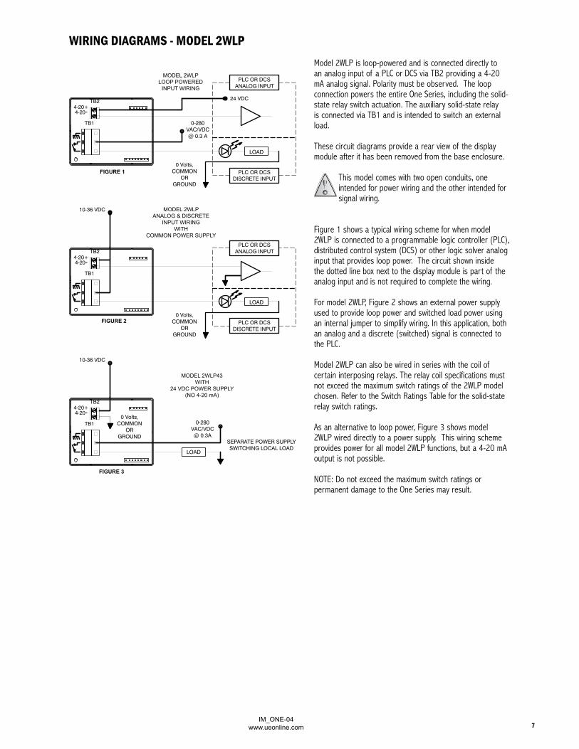
LADDER LOGIC EXAMPLE(used for detecting the pulsed output)
Ladder logic for One Series 2-wire model 2W2DPulse-on-rise output (25 mSec)
SELECTING AN INTRINSIC SAFETy BARRIER (Model 2W2D only)WARNING: INSTALLATION OF INTRINSICALLY SAFE CIRCUITS MUST BE PERFORMED IN ACCORDANCE WITH THE REQUIREMENTS OF THE GOVERNMENT AND/OR OTHER LOCAL AUTHORITY HAVING JURISDICTION. SYSTEM COMPONENTS AND INSTALLATION METHODS MUST BE APPROVED BY THE APPROPRIATE RECOGNIZED APPROVAL AUTHORITY.
The information provided below is for reference only and is intended to act as a guide in the selection of a suitable I.S. Barrier. Please reference one of the following I.S. control drawings for installation details and device entity parameters:
A-62174-19 (North American, Class, Division & Zone based installations) A-62174-20 (European, Class, Zone based installations)
There are two general types of Intrinsic Safety Barriers, shunt diode (passive) safety barriers and transformer isolated barriers. Shunt diode safety barriers are the simplest and least expensive type of I.S. interface for protecting circuits in hazardous areas. Diode safety barriers must be installed with a suitable (<1Ω) earth ground. Isolated barriers offer simplified installation, since there is no requirement for the ground, but are generally more expensive than the diode safety barriers.
Shunt Diode Safety Barriers:The entity parameters of diode safety barriers suitable for use with the 2W2D models are:
V max = 28 Volts I max = 93 mA
Because the 2W2D model derives its operating power from the input of the host device to which it is connected it is also important to select a barrier with a low leakage current. This is typically specified as Vwkg , the working voltage , at which 10 uA of leakage current will occur. Vwkg > 25 Volts; at 10 uA of leakage current is ideal
Suggested Sources:Pepperl + Fuchs® Model No. Z787 MTL® Model No. 7087+
Transformer Isolated Barriers: Due to the unique method by which the model 2W2D operates, a specifically designed isolated barrier must be used:
The isolated barrier is available from MTL: • Order Part Number MTL 5012S directly from MTL or any of its distributors.
IM_ONE-04www.ueonline.com18
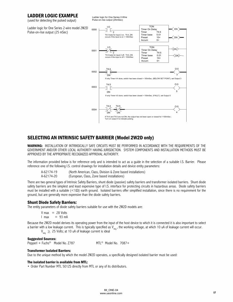
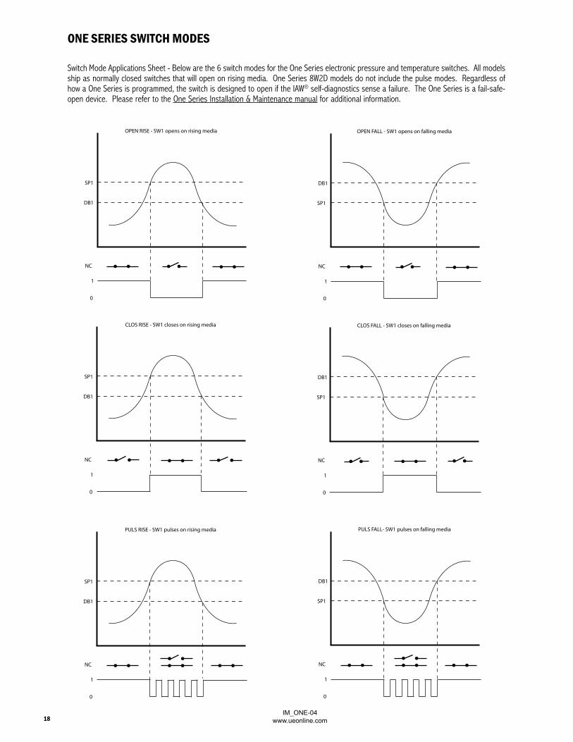
ONE SERIES SWITCH MODES
Switch Mode Applications Sheet - Below are the 6 switch modes for the One Series electronic pressure and temperature switches. All models ship as normally closed switches that will open on rising media. One Series 8W2D models do not include the pulse modes. Regardless of how a One Series is programmed, the switch is designed to open if the IAW® self-diagnostics sense a failure. The One Series is a fail-safe-open device. Please refer to the One Series Installation & Maintenance manual for additional information.
SP1
DB1
NC
1
0
OPEN RISE - SW1 opens on rising media
DB1
SP1
NC
1
0
OPEN FALL - SW1 opens on falling media
DB1
SP1
NC
1
0
CLOS FALL - SW1 closes on falling media
DB1
SP1
NC
1
0
PULS FALL- SW1 pulses on falling media
SP1
DB1
NC
1
0
PULS RISE - SW1 pulses on rising media
SP1
DB1
NC
1
0
CLOS RISE - SW1 closes on rising media

IM_ONE-04www.ueonline.com 19
Application Note: One Series model 8W2D contains two SPST solid-state relay (SSR) switches. Each switch has a fully adjustable and independent set point, deadband (hysteresis) and switch mode. The switches can be combined to create a Form C (SPDT) contact. Please see the diagram below.
The One Series 8W2D contains two potential-free SSR switches that can be wired in series or parallel for switch logic applications. This makes it possible to wire the switches in series and program them for Window Mode operation where a specific media range can be detected. Please see the diagram below.
One Series 8W2Dprogrammed for Form C(SPDT) contact
One Series 8W2Dprogrammed forWindow Mode
SP1 = SP2DB1 = DB2
CLOS RISE - SW1 closes on rising mediaOPEN RISE - SW2 opens on rising media
0
1
1
0
SW1
SW2
SP2 DB2
CLOS RISE - SW1 closes on rising mediaOPEN RISE - SW2 opens on rising media
SW1 & SW2 are wired in series
0
1
1
0
SW1
SW2
DB1SP1
1
0OUT
CNC
NO
CNCNO
OUT
SW1 SW2
ONE SERIES SWITCH MODES

IM_ONE-04www.ueonline.com20
Error Message Error Code Probable Causes Try This First Other Options
EEPROM CS ERR 0002Checksum error on serial EEPROM (used to sore config. Cal. Data).
Cycle power. In most cases, it should clear the error and operate normally.
If error does not clear, unit has to be returned for factory repair
FACT
Factory programming mode. Usually caused either by shorting the pins internally or touching the enclosure while energized.
Inspect pins on the rear of the display and make sure they are not touching one another or the case. Cycle power and error should clear.
If error does not clear, unit has to be returned for factory repair
KEY STUCK 0008Keypad button stuck. Cycle power. In most cases, it should clear the
error and operate normally.If error does not clear, unit has to be returned for factory repair.
OVER RNG 0020
Process exceeding 110% of range. Automatic reset when process variable returns to normal.
If error continues, check for sensor damage due to over/under range exposure. Return for repair.
OVER RNG 0200
Process exceeding 150% of range. Automatic reset when process variable returns to normal.
If error continues, check for sensor damage due to over/under range exposure. Return for repair.
OVER RNG 0220
Extreme over range for all sensors except the 0 to 5 psi range.
Automatic reset when process variable returns to normal.
If error continues, check for sensor damage due to over/under range exposure. Return for repair.
UNDER/OVER RNG
0330
Extreme under and over range for the 0 to 5 psi range.
Automatic reset when process variable returns to normal.
If error continues, check for sensor damage due to over/under range exposure. Return for repair.
P/S OUT OF RNG 0040
Voltage into unit’s regulator is less than 3.5 Volts or more than 35 Volts. Also if series load resistance is too high (2-Wire devices only).
Check Voltage input to unit and the load resistance (check the installation sheet for upper and lower limit values of the series load). Error will clear if conditions return to normal.
Cycle power. If error returns, return for factory repair.
PLUG 8000Plugged port condition exists. Is pressure dynamic? Is sensor plugged? Is plug
port setup OK?Turn feature off. If error continues, return for repair.
REF. FAULT 1000The onboard reference voltage is out of range.
Ref. Fault can be caused by the presence of electrical noise. Eliminate electrical noise sources.
If problem persists, return product to factory for repair.
SENSOR FAULT 0400Sensor has an open circuit. Check for broken wire or unplugged sensor
connection. Cycle power.If problem persists, return product to factory for repair.
SENSOR FAULT 0800Sensor has a short circuit. Check for shorted connection on the sensor.
Cycle power.If problem persists, return product to factory for repair.
SWITCH FAULT 0080
Switch voltage is too high in closed state, or too low in open state. Only happens on 2W2D and 2W3A models. Note: on 2W3A models, this may have been caused by connecting unit to power with no load in series or by touching pins to case.
Cycle Power. In most cases, it should clear the error and operate normally.
If fault persists, return product to factory for repair.
WDOG 0004
Watchdog timed out. Could be caused by transients on power supply during power up or unit connected to a load resistance that is too high.
Review load resistance with customer. Cycle power. In most cases, it should clear the error and operate normally.
If error continues, try a different power supply or unit has to be returned to factory for repair.
All errors that start with two
alphanumeric digitsEX??
Causes are various. Cycle power. In most cases, it should clear the error and operate normally.
If error does not clear, unit has to be returned for factory repair.
Possible Corrective Actions
ONE SERIES ERROR MESSAGESIf an error message appears on the One Series display, an error code can be obtained by pressing both keypad buttons simultaneously. Please provide this code if calling UE Technical Sales for assistance.

IM_ONE-04www.ueonline.com 21
W
WWW W
2W4D
PSIBAR/MBARKPA/MPAKg/cm2
“WC
SETUNITS
°F°C
N/A ON 8W2D
MODEL 2WLP AND 8W2D ONLY
**8W2D ONLY

IM_ONE-04www.ueonline.com22
Models 8W2D and 2WLP (Dual Conduit shown with Temperature Sensor)
Models 4W3A, 2W2D, 2W4D and 2W3A(Single Conduit shown with Gauge Pressure Sensor)
DIMENSIONAL DRAWINGS

IM_ONE-04www.ueonline.com 23
Temperature Model L
Temperature Model R
SENSOR OPTIONS
Gauge Pressure Differential Pressure
2
Temperature Models H & C
1.06[26.9mm]
1/2”-14 NPT (FEMALE)1/4”-18 NPT (MALE)BOTH ENDS3.0
[76.2mm]
1.06[26.9mm]

IM_ONE-04www.ueonline.com24
U N I T E D E L E C T R I C C O N T R O L S180 Dexter Ave. P.O. Box 9143, Watertown, MA 02472-9143 USA
617 926-1000 Fax 617 926-2568www.ueonline.com
RECOMMENDED PRACTICES AND WARNINGS
United Electric Controls Company recommends careful consideration of the following factors when specifying and installing UE pressure and temperature units. Before installing a unit, the Installation and Maintenance instructions provided with unit must be read and understood.
• To avoid damaging unit, proof pressure and maximum temperature limits stated in literature and on nameplates must never be exceeded, even by surges in the system. Operation of the unit up to maximum pressure or temperature is acceptable on a limited basis (e.g., start-up, testing) but continuous operation must be restricted to the designated adjustable range. Excessive cycling at maximum pressure or temperature limits could reduce sensor life.
• A back-up unit is necessary for applications where damage to a primary unit could endanger life, limb or property. A high or low limit switch is necessary for applications where a dangerous runaway condition could result.
• The adjustable range must be selected so that incorrect, inadvertent or malicious setting at any range point cannot result in an unsafe system condition.
• Install unit where shock, vibration and ambient temperature fluctuations will not damage unit or affect operation. When applicable, orient unit so that moisture does not enter the enclosure via the electrical connection. When appropriate, this entry point should be sealed to prevent moisture entry.
• Unit must not be altered or modified after shipment. Consult UE if modi-fication is necessary.
• Monitor operation to observe warning signs of possible damage to unit, such as drift in set point or faulty display. Check unit immediately.
• Preventative maintenance and periodic testing is necessary for critical applications where damage could endanger property or personnel.
• Electrical ratings stated in literature and on nameplate must not be exceeded. Overload on a switch can cause damage, even on the first cycle. Wire unit according to local and national electrical codes, using wire size recommended in installation sheet.
• Do not mount unit in ambient temp. exceeding published limits.
LIMITED WARRANTYSeller warrants that the product hereby purchased is, upon delivery, free from defects in material and workmanship and that any such product which is found to be defective in such workmanship or material will be repaired or replaced by Seller (Ex-works, Factory, Watertown, Massachusetts. INCOTERMS); provided, however, that this warranty applies only to equipment found to be so defective within a period of 36 months from the date of manufacture by the Seller. Seller shall not be obligated under this warranty for alleged defects which examina-tion discloses are due to tampering, misuse, neglect, improper storage, and in any case where products are disassembled by anyone other than authorized Seller’s representatives. EXCEPT FOR THE LIMITED WARRANTY OF REPAIR AND REPLACEMENT STATED ABOVE, SELLER DISCLAIMS ALL WARRANTIES WHATSOEVER WITH RESPECT TO THE PRODUCT, INCLUDING ALL IMPLIED WARRANTIES OF MERCHANTABILITY OR FITNESS FOR ANY PARTICULAR PURPOSE.
LIMITATION OF SELLER’S LIAbILITYSELLER’S LIABILITY TO BUYER FOR ANY LOSS OR CLAIM, INCLUDING LIABIL-ITY INCURRED IN CONNECTION WITH (I) BREACH OF ANY WARRANTY WHAT-SOEVER, EXPRESSED OR IMPLIED, (II) A BREACH OF CONTRACT, (III) A NEGLI-GENT ACT OR ACTS (OR NEGLIGENT FAILURE TO ACT) COMMITTED BY SELLER, OR (IV) AN ACT FOR WHICH STRICT LIABILITY WILL BE INPUTTED TO SELLER, IS LIMITED TO THE “LIMITED WARRANTY” OF REPAIR AND/OR REPLACEMENT AS SO STATED IN OUR WARRANTY OF PRODUCT. IN NO EVENT SHALL THE SELLER BE LIABLE FOR ANY SPECIAL, INDIRECT, CONSEqUENTIAL OR OTHER DAMAGES OF A LIKE GENERAL NATURE, INCLUDING, WITHOUT LIMITATION, LOSS OF PROFITS OR PRODUCTION, OR LOSS OR EXPENSES OF ANY NATURE INCURRED BY THE BUYER OR ANY THIRD PARTY.
UE specifications subject to change without notice.
CP08114000