Embed Size (px)
Citation preview

PRODUCT FEATURES
• All Solid State Design
• Fully Adjustable Set Point and Deadband
• I Am Working Diagnostic Signal
• Class I, Division 2 Approved
• Wide Variety of Switching Outputs and Sensor Options
ELECTRONIC PRESSURE, DIFFERENTIAL PRESSURE AND TEMPERATURE SWITCHES
One Series O
ne
Se
ries
U N I T E D E L E C T R I C C O N T R O L S ONE-B-01

2 U N I T E D E L E C T R I C C O N T R O L S O N E - B - 0 1
One Series
O N E - B - 0 1 U N I T E D E L E C T R I C C O N T R O L S 3
O n e S e r i e s
One Series Electronic Pressure, Differential Pressure & Temperature Switches are designed for critical alarm and shutdown applications in harsh hazardous environments. A local indicator and remote I Am Working (IAW®) status signal provide continuous notifi cation that the device is powered, healthy and whether the switch has tripped, assuring the operator that the One Series will perform when called upon.
Low level DC outputs (output confi gurations A and B) may be used to trigger control circuits or as a discrete input to a process computer (DCS or PLC).
A 13 Amp VAC solid-state relay (output confi guration C) provides local high level switching for actuation or shutdown of your system.
The switch output mode may be confi gured by the user in the fi eld without re-wiring. An optional 4 to 20 mA analog output allows remote monitoring and trending of the process variable.
The self-contained, compact package allows for easy retrofi t of mechanical switches or transmitters.
115 VAC and 230 VAC input/output confi gurations enable the One Series to be powered by an AC source and switch AC loads. Approved for Division 2 hazardous locations and harsh environmental conditions, this rugged design will stand up to your most demanding applications.
features
• 18-30 VDC, 115 VAC or 230 VAC power supply
• Real time local digital display of process variable
• Optional 4 to 20 mA analog output
• All solid-state; no moving parts
• Set point and deadband adjustable over the sensors full operating range
• Solid-state switching provides extended switch life with no contact wear
• Pipe or surface mounting
• Approved for Division 2 locations; Enclosure type 4X
• 3 year warranty
One Series with remote temperature sensor, digital display and 100 mA switch output
One Series with 115 VAC power supply, top enclosure contains separate high voltage and low voltage terminal blocks and pass-through conduit connectors
On
e S
eri
es
overview

2 U N I T E D E L E C T R I C C O N T R O L S O N E - B - 0 1
One Series
O N E - B - 0 1 U N I T E D E L E C T R I C C O N T R O L S 3
O n e S e r i e s
One Series with 3A rated sanitary sensor
One Series with gauge pressure sensor and LEXAN® cover removed
One Series with inches-of-water column, differential pressure sensor (shown with optional barb fi ttings)
One Series with local temperature sensor (shown with optional PF73 compression fi tting)
One Series with stainless-steel differential pressure sensor

4 U N I T E D E L E C T R I C C O N T R O L S O N E - B - 0 1
One Series O
ne
Se
rie
s
O N E - B - 0 1 U N I T E D E L E C T R I C C O N T R O L S 5
O n e S e r i e s
FROM MECHANICAL SWITCH:
• AC voltage must be located nearby for the pump
• This switch is in close proximity to the pump
• The switch breaks the power supply leg to the pump (load)
TO ONE SERIES:
• Pull one additional neutral wire from the junction box to the One Series switch
• Just like the mechanical switch, the SSR breaks the power supply leg to the pump (load)
REPLACING A MECHANICAL SWITCH WITH THE ONE SERIES REQUIRES ONE ADDITIONAL WIRE
Pipelines & Pumping Stations Chemical Plants and Refineries
TYPICAL MECHANICAL SWITCH
ApplicationS
The One Series combines the best features of traditional switches and transmitters in one package. Use it for all threshold detection and switching applications.

4 U N I T E D E L E C T R I C C O N T R O L S O N E - B - 0 1
One Series
On
e S
eri
es
O N E - B - 0 1 U N I T E D E L E C T R I C C O N T R O L S 5
O n e S e r i e s
TRADITIONAL SWITCH FEATURES:
• AC or DC operation
• Low cost
• Simple to wire and operate
• Direct load switching
TRANSMITTER FEATURES:
• Solid-state performance. No moving parts
• Live zero, “health indication”
• Remote indication of process variable
THE ONE SERIES COMBINES THE BEST FROM EACH!
• AC or DC operation
• Solid-state output. No moving parts. Reliable operation
• Communicates “I Am Working” and “I Have Switched” status
• Local and remote status indicator
• Local display of process variable
• Local setting of set point, deadband and switch mode
• Local memory of minimum and maximum process extremes
• Combines a gauge, a transducer and a switch all in one package; using one process connection
• Optional 4-20 mA trending output
• Economical; about half the cost of a process transmitter
Rotating Equipment
Rugged construction, wide media compatibility and flexible mounting options combine to make the One Series the ideal choice for monitoring and controlling critical pressure and temperature thresholds for a variety of process applications. It can also help you satisfy standards such as ISA S84.01 and IEC 61508 in areas such as redundancy, diverse technologies and reduced testing intervals. The One Series employs solid-state technology with no moving parts and is approved for use in Class I, Division 2 hazardous locations by UL for USA and Canadian installations. All pressure and differential pressure models include FM approvals.

6 U N I T E D E L E C T R I C C O N T R O L S O N E - B - 0 1
One Series O
ne
Se
rie
s
O N E - B - 0 1 U N I T E D E L E C T R I C C O N T R O L S 7
O n e S e r i e s
technology
UNIQUE IAW® FUNCTION
The One Series provides a continuous indication of its health and the switch output status, both locally and remotely. An LED on the front panel and a discrete logic output signal are used to communicate three states:
• I Am Working but I Have Not Switched
• I Am Working and I Have Switched
• I Am Not Working
The One Series IAW® feature continuously monitors the health of the sensor, software, micropro-cessor and power supply. Used in conjunction with the standard switch output, the IAW® signal can also help satisfy many DPDT requirements. Functions of the IAW® signal are as follows:
100% SET POINT AND DEADBAND ADJUSTMENT
Set point and deadband values are adjustable over the full range span using a convenient, simple to operate, front panel keypad. Access to the programming mode requires a simple, yet tamper resistant keying sequence... It’s better than password protection!
The easy-to-use local programmability of the One Series provides the following benefits:
• Eliminates the need to trade-off wide range adjustability to achieve a narrow deadband
• No more guessing about the set point or deadband values or the effects of hysteresis on the switch. All values may be displayed locally with the touch of a single button and then precisely adjusted to any point in the operating range
• Single digit (or better) resolution for both the set point and the deadband values. See DISPLAY RESOLUTION TABLE
PROCESS VARIABLE EXTREMES STORED IN NON-VOLATILE MEMORY
System pressure or temperature extremes are retained in the One Series’ non-volatile memory, assisting in troubleshooting problems. The One Series continuously captures high and low pressure or temper-ature extremes values, providing a readout and a tamper-resistant key sequence for resetting.
• Captures and stores extreme swings (peaks and valleys) of the process variable
• Use the - extreme as a “leak down” tester
• Use the + extreme to evaluate relief valve and rupture disc performance
• Local display of +/- extreme values, with the push of a single button
IAW® Signal Interpretation
IAW® output “On” continuously Normal operation, unit operating properly
IAW® output pulsed “On” and “Off” Beyond set point, unit operating properly
IAW® output “Off” Loss of power or unit inoperable

6 U N I T E D E L E C T R I C C O N T R O L S O N E - B - 0 1
One Series
On
e S
eri
es
O N E - B - 0 1 U N I T E D E L E C T R I C C O N T R O L S 7
O n e S e r i e s
UNIQUE SWITCH OPERATING MODE
The One Series provides four convenient switch operating modes which determine the function of the switch output, deadband, and IAW® LED status indicator signal. The local and remote IAW® signals will flash when the unit is in a tripped condition. The desired switch operating mode can be selected from one of four options:
• High Limit Alarm - Close on Rise (NO)
• High Limit Shutdown - Open on Rise (NC)
• Low Limit Alarm - Close on Fall (NO)
• Low Limit Shutdown - Open on Fall (NC)
The switch operating mode provides the following benefits:
• Wire the unit, then select your desired switch output (NO or NC) from a menu on the One Series’ display
• Select the operation of the switch, deadband, status LED and IAW® output with a few simple keystrokes
• Eliminate wiring hassles with a single button; reconfigure rather than rewire the product if the application or requirements change
NOTE: For dual, independently-set outputs, see One Series Dual Bulletin.
EXCELLENT MEDIA COMPATIBILITY
Gauge pressure: Wetted materials include a 316 stainless steel pressure connection, ceramic pressure sensor and your choice of O-ring material. The piezoresistive ceramic sensor is compatible with most media except a few aggressive acids.
• Sanitary pressure: 316L stainless steel sanitary process fitting
• Stainless-steel differential pressure: 316 welded sensor compatible with most media
• Differential pressure (dry only): compatible with dry air and inert gases
• Temperature: 304 stainless steel sensor sheath
OUTSTANDING REPEATABILITY
A 10 bit analog-to-digital converter and software calibration provide a highly accurate and stable reading of the process variable. Calibration constants are stored in non-volatile memory to ensure set point repeatability and eliminate the need to recalibrate the instrument.
• Switch repeatability: ± 0.2% of full scale
• Display and 4-20mA accuracy: ± 1.0% of full scale
FIELD TEST AND SET
After removing the protective LEXAN® cover, the user may easily vary the set point and/or deadband values to verify proper switch operation and check process extremes. Switch modes can be changed from Normally Open to Normally Closed without wiring changes.
8 U N I T E D E L E C T R I C C O N T R O L S O N E - B - 0 1
One Series O
ne
Se
rie
s
O N E - B - 0 1 U N I T E D E L E C T R I C C O N T R O L S 9
O n e S e r i e s
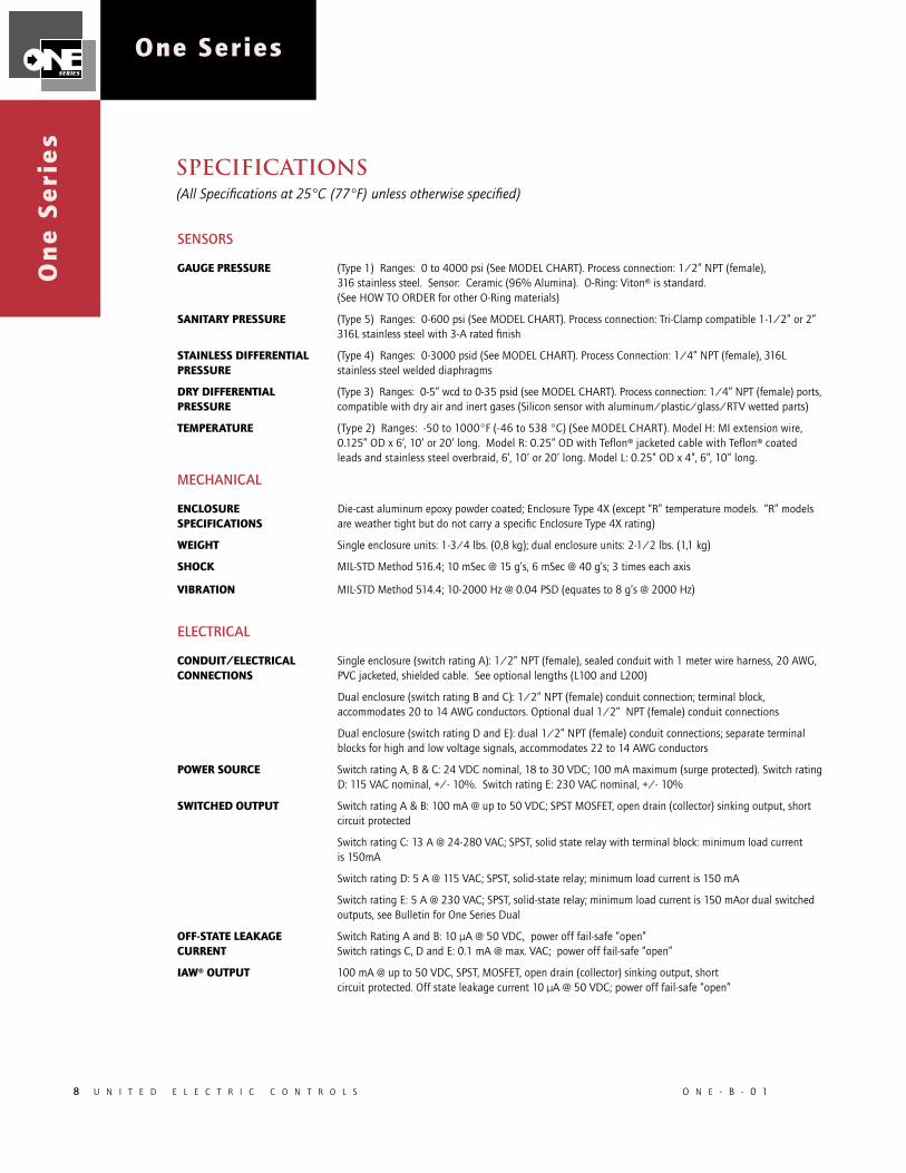
SENSORS
GAUGE PRESSURE (Type 1) Ranges: 0 to 4000 psi (See MODEL CHART). Process connection: 1/2” NPT (female), 316 stainless steel. Sensor: Ceramic (96% Alumina). O-Ring: Viton® is standard. (See HOW TO ORDER for other O-Ring materials)
SANITARY PRESSURE (Type 5) Ranges: 0-600 psi (See MODEL CHART). Process connection: Tri-Clamp compatible 1-1/2” or 2” 316L stainless steel with 3-A rated finish
STAINLESS DIFFERENTIAL (Type 4) Ranges: 0-3000 psid (See MODEL CHART). Process Connection: 1/4” NPT (female), 316L PRESSURE stainless steel welded diaphragms
DRY DIFFERENTIAL (Type 3) Ranges: 0-5” wcd to 0-35 psid (see MODEL CHART). Process connection: 1/4” NPT (female) ports, PRESSURE compatible with dry air and inert gases (Silicon sensor with aluminum/plastic/glass/RTV wetted parts)
TEMPERATURE (Type 2) Ranges: -50 to 1000°F (-46 to 538 °C) (See MODEL CHART). Model H: MI extension wire, 0.125” OD x 6’, 10’ or 20’ long. Model R: 0.25” OD with Teflon® jacketed cable with Teflon® coated leads and stainless steel overbraid, 6’, 10’ or 20’ long. Model L: 0.25” OD x 4”, 6”, 10” long.
MECHANICAL
ENCLOSURE Die-cast aluminum epoxy powder coated; Enclosure Type 4X (except “R” temperature models. “R” models SPECIFICATIONS are weather tight but do not carry a specific Enclosure Type 4X rating)
WEIGHT Single enclosure units: 1-3/4 lbs. (0,8 kg); dual enclosure units: 2-1/2 lbs. (1,1 kg)
SHOCK MIL-STD Method 516.4; 10 mSec @ 15 g’s, 6 mSec @ 40 g’s; 3 times each axis
VIBRATION MIL-STD Method 514.4; 10-2000 Hz @ 0.04 PSD (equates to 8 g’s @ 2000 Hz)
ELECTRICAL
CONDUIT/ELECTRICAL Single enclosure (switch rating A): 1/2” NPT (female), sealed conduit with 1 meter wire harness, 20 AWG, CONNECTIONS PVC jacketed, shielded cable. See optional lengths (L100 and L200)
Dual enclosure (switch rating B and C): 1/2” NPT (female) conduit connection; terminal block, accommodates 20 to 14 AWG conductors. Optional dual 1/2” NPT (female) conduit connections
Dual enclosure (switch rating D and E): dual 1/2” NPT (female) conduit connections; separate terminal blocks for high and low voltage signals, accommodates 22 to 14 AWG conductors
POWER SOURCE Switch rating A, B & C: 24 VDC nominal, 18 to 30 VDC; 100 mA maximum (surge protected). Switch rating D: 115 VAC nominal, +/- 10%. Switch rating E: 230 VAC nominal, +/- 10%
SWITCHED OUTPUT Switch rating A & B: 100 mA @ up to 50 VDC; SPST MOSFET, open drain (collector) sinking output, short circuit protected
Switch rating C: 13 A @ 24-280 VAC; SPST, solid state relay with terminal block: minimum load current is 150mA
Switch rating D: 5 A @ 115 VAC; SPST, solid-state relay; minimum load current is 150 mA
Switch rating E: 5 A @ 230 VAC; SPST, solid-state relay; minimum load current is 150 mAor dual switched outputs, see Bulletin for One Series Dual
OFF-STATE LEAKAGE Switch Rating A and B: 10 µA @ 50 VDC, power off fail-safe “open” CURRENT Switch ratings C, D and E: 0.1 mA @ max. VAC; power off fail-safe “open”
IAW® OUTPUT 100 mA @ up to 50 VDC, SPST, MOSFET, open drain (collector) sinking output, short circuit protected. Off state leakage current 10 µA @ 50 VDC; power off fail-safe “open”
SPECIFICATIONS(All Specifications at 25°C (77°F) unless otherwise specified)

8 U N I T E D E L E C T R I C C O N T R O L S O N E - B - 0 1
One Series
On
e S
eri
es
O N E - B - 0 1 U N I T E D E L E C T R I C C O N T R O L S 9
O n e S e r i e s
IAW® OUTPUT PULSE RATE 25 mSec on, 25 mSec off
OPTIONAL ANALOG OUTPUT 4 to 20 mA sourcing output, non-isolated, proportional to sensor input range, load resistance 500Ω maximum
EMI/RFI Complies with CE EMC requirements EN50081-1, EN50082-2 (switch rating B and C only)
EMISSION Conducted emission EN55011 class A; Radiated emission EN55011 class A
IMMUNITY Electrostatic discharge EN61000-4-2; Conducted disturbances (RF) acc. IEC 1000-4-6; Radiated E- fields (RF) acc IEC 1000-4-3, acc ENV50204; Surge withstanding IEC 1000-5; Transient withstanding EN 61000-4-4
OPERATING
RANGES See MODEL CHART for pressure, differential pressure and temperature ranges
SET POINT Adjustable over the full range span. See MODEL CHART
DEADBAND Adjustable over the full range span. See MODEL CHART
MAXIMUM OVER RANGE See MODEL CHART. N/A for temperature ranges
SET POINT REPEATABILITY ±0.2% of maximum range value
ACCURACY Switch point/indication: ±1.0% of maximum range value Analog output: ±1.0% of maximum range value
MEDIA TEMPERATURE EFFECTS ±1.0% of maximum range from 32 to 158°F (0 to 70°C)
LONG-TERM STABILITY ±0.25% of range per year, maximum
SWITCH RESPONSE TIME 25 mSec typically, 200 mSec maximum
GENERAL FEATURES
AMBIENT TEMPERATURE Operating: -22 to 158°F (-30 to 70°C) Storage: -22 to 176°F (-30 to 80°C) Dry Differential Pressure Model: -22 to 122°F (-30 to 50°C)
MEDIA TEMPERATURE FOR Sensor type 1: Limited by O-ring material. See HOW TO ORDER.GAUGE PRESSURE MODELS Sensor type 5: 0 to 266°F (-17 to 130°C)
MEDIA TEMPERATURE FOR -20 to 150°F (-28 to 65°C) @ 65 psiDIFFERENTIAL PRESSURE -20 to 140°F (-28 to 60°C) @ 80 psiMODELS (SENSOR 3) -20 to 120°F (-28 to 48°C) @ 120 psi
STAINLESS DIFFERENTIAL PRESSURE MODELS (SENSOR 4) 0 to 257°F (-17 to 125°C)
MEDIA TEMPERATURE FOR -94 to 550°F (-70 to 288°C) (Models L & R)TEMPERATURE MODELS -94 to 1150°F (-70 to 621°C) (Model H)
LOCAL DIGITAL DISPLAY 2 Row by 16 character LCD display for indication of programming parameters and process variable; also displays extreme (min/max) pressure or temperature values
LOCAL IAW® STATUS LED Local IAW® LED to indicate switch state and health status
FIELD ACCESSIBLE PROGRAMMING Convenient keypad allows for easy product configuration and adjustment
MEMORY All programmed data stored in non-volatile memory (saved if power lost)
SWITCH OPERATING MODES Field programmable for open or close on rising or falling condition
10 U N I T E D E L E C T R I C C O N T R O L S O N E - B - 0 1
One Series O
ne
Se
rie
s
O N E - B - 0 1 U N I T E D E L E C T R I C C O N T R O L S 11
O n e S e r i e s
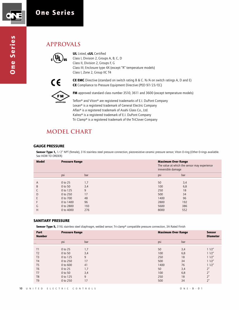
approvalsUL Listed, cUL Certified Class I, Division 2, Groups A, B, C, DClass II, Division 2, Groups F, GClass III; Enclosure type 4X (except “R” temperature models)Class I, Zone 2, Group IIC T4
CE EMC Directive (standard on switch rating B & C. N/A on switch ratings A, D and E)CE Compliance to Pressure Equipment Directive (PED 97/23/EC)
FM approved standard class number 3510, 3611 and 3600 (except temperature models)
Teflon® and Viton® are registered trademarks of E.I. DuPont CompanyLexan® is a registered trademark of General Electric CompanyAflas® is a registered trademark of Asahi Glass Co., Ltd.Kalrez® is a registered trademark of E.I. DuPont CompanyTri Clamp® is a registered trademark of the TriClover Company
model chart
GAUGE PRESSURE Sensor Type 1, 1/2” NPT (female), 316 stainless steel pressure connection, piezoresistive ceramic pressure sensor, Viton O-ring (Other 0-rings available. See HOW TO ORDER)
Model Pressure Range Maximum Over Range The value at which the sensor may experience irreversible damage
psi bar psi bar
A 0 to 25 1,7 50 3,4 B 0 to 50 3,4 100 6,8 C 0 to 125 9 250 18 D 0 to 250 17 500 34 E 0 to 700 48 1400 96 F 0 to 1400 96 2800 192 G 0 to 2800 193 5600 386 H 0 to 4000 276 8000 552
SANITARY PRESSURE Sensor Type 5, 316L stainless steel diaphragm, welded sensor; Tri-clamp® compatible pressure connection, 3A Rated Finish
Part Pressure Range Maximum Over Range Sensor Number Diameter
psi bar psi bar
T1 0 to 25 1,7 50 3,4 1 1⁄2” T2 0 to 50 3,4 100 6,8 1 1⁄2” T3 0 to 125 9 250 18 1 1⁄2” T4 0 to 250 17 500 34 1 1⁄2” T5 0 to 600 41 1400 76 1 1⁄2” T6 0 to 25 1,7 50 3,4 2” T7 0 to 50 3,4 100 6,8 2” T8 0 to 125 9 250 18 2” T9 0 to 250 17 500 34 2”

10 U N I T E D E L E C T R I C C O N T R O L S O N E - B - 0 1
One Series
On
e S
eri
es
O N E - B - 0 1 U N I T E D E L E C T R I C C O N T R O L S 11
O n e S e r i e s
DIFFERENTIAL PRESSURE (dry air, inert gas)
Sensor Type 3, 1/4” NPT (female) pressure connections, silicon sensor, with aluminum/plastic/glass/RTV wetted parts. Suitable for sensing of dry air and inert gases. Optional plastic barb fittings available (Kit 62169-19). Ambient temperature range -22°F to 122°F (-30°C to 50°C)
Model Differential Pressure Range (1) Differential Over Working Range Pressure (2) Pressure (3)
psid (“wcd) bar/(mbar) psid bar psig bar
K1 (0 to 5) (12,4) 1 0,1 6 0,4 K2 (0 to 25) (62,2) 20 1,4 100 6,9 K3 (0 to 80) (199) 20 1,4 100 6,9 K4 0 to 5 (344,7) 30 2,1 100 6,9 K5 0 to 12 (827,4) 60 4,1 100 6,9 K6 0 to 35 2,41 100 6,9 100 6,9
DIFFERENTIAL PRESSURE (Stainless, suitable for wet media)
Sensor Type 4, 316 welded stainless steel diaphragms with 1/4” NPT (female) pressure connections
Model Differential Pressure Range (1) Differential Over Working Range Pressure (2) Pressure (3)
psid bar psid bar psi bar
W4 0 to 100 6,9 300 21 1800 124 W5 0 to 300 21 900 62 2750 190 W6 0 to 1000 69 2000 138 2750 190 W7 0 to 3000 207 3000 207 3250 224
(1) Range is defined as the range of differential pressure between process inputs for which the sensor will operate within specified functional tolerances
(2) Differential Over Range Pressure is defined as the maximum difference in pressure between the process inputs. Exceeding this pressure differential at any working pressure may permanently damage the sensor performance
(3) Working Pressure is defined as the maximum pressure at either process input. Exceeding this pressure at either process input individually or simultaneously may permanently damage the sensor performance
TEMPERATURESensor Type 2, 0.25” OD sensor housing, 304 stainless steel, 100 ohm RTD temperature sensor. NOTE: Must order PF73 compression fitting or SA6213-348 union connection if threaded connection is required. Accessory thermowells are also available (see page 14)
Model Temperature Range Maximum Over Range Description The value at which the sensor may experience irreversible damage
L1 -50 to 450°F (-45 to 232°C) 550°F (288°C) Local sensor, 4” long
L2 -50 to 450°F (-45 to 232°C) 550°F (288°C) Local sensor, 6” long
L3 -50 to 450°F (-45 to 232°C) 550°F (288°C) Local sensor, 10” long
R1 -50 to 450°F (-45 to 232°C) 550°F (288°C) Remote sensor, 6” long with 6’ Teflon® extension wire
R2 -50 to 450°F (-45 to 232°C) 550°F (288°C) Remote sensor, 6” long with 10’ Teflon® extension wire
R3 -50 to 450°F (-45 to 232°C) 550°F (288°C) Remote sensor, 6” long with 20’ Teflon® extension wire
H1 -50 to 1000°F (-45 to 538°C) 1150°F (621°C) Remote sensor, high temp., 2.5” long with 6’ MI ext. wire
H2 -50 to 1000°F (-45 to 538°C) 1150°F (621°C) Remote sensor, high temp., 2.5” long with 10’ MI ext. wire
H3 -50 to 1000°F (-45 to 538°C) 1150°F (621°C) Remote sensor, high temp., 2.5” long with 20’ MI ext. wire
H4 -50 to 450°F (-45 to 232°C) 1150°F (621°C) Remote sensor, 2.5” long with 6’ MI ext. wire
H5 -50 to 450°F (-45 to 232°C) 1150°F (621°C) Remote sensor, 2.5” long with 10’ MI ext. wire
H6 -50 to 450°F (-45 to 232°C) 1150°F (621°C) Remote sensor, 2.5” long with 20’ MI ext. wire

12 U N I T E D E L E C T R I C C O N T R O L S O N E - B - 0 1
One Series O
ne
Se
rie
s
O N E - B - 0 1 U N I T E D E L E C T R I C C O N T R O L S 13
O n e S e r i e s
Build a part number by selecting appropriate code for each feature category. Example: D1A1B2NM446
D 1 A 1 B 2 N M446 ORDERING (see next page)CODE DESCRIPTION
SETTING/INDICATION METHOD D User adjustable, digital indicating configuration
SERIES DESIGNATION 1 Designation for One Series product line with single switch output
SWITCH RATING/TERMINATION/POWER SUPPLY (ALSO SEE LIST OF OPTIONS) A MOSFET Open drain (collector) output with flying lead-wires B MOSFET Open drain (collector) output with terminal block (upper enclosure included) C 13A VAC solid-state relay with terminal block (upper enclosure included) D 5A VAC solid-state relay with 115 VAC internal power supply and terminal blocks (upper enclosure included, dual conduit ports standard) E 5A VAC solid-state relay with 230 VAC internal power supply and terminal blocks (upper enclosure included, dual conduit ports standard)SENSOR TYPE 1 Gauge pressure, 316 stainless steel 1/2” NPT (female) pressure connection, ceramic sensor 2 Temperature Sensor (Thermowell Information: see page 14) 3 Differential pressure (dry air), silicon sensor, 1/4” NPT (female) pressure connections, 180° opposite 4 Differential pressure, 316 welded stainless steel diaphragms with 1/4” NPT (female) pressure connections 5 Sanitary pressure, 316L stainless steel, 1 1/2” or 2” Tri-Clamp® connection
MODEL RANGE A-H Pressure, NPT T1-T9 Pressure, sanitary K1-K6 Differential pressure, dry W4-W7 Differential pressure, stainless L1-L3 Temperature, local R1-R3 Temperature, remote/teflon H1-H6 Temperature, remote/MI
O-RING MATERIAL (SENSOR TYPE 1 ONLY) 0 Viton®; media temperature 0 to 257oF (-17 to 125oC) 1 Aflas®; media temperature 32 to 200oF (0 to 93oC) 2 Buna N; media temperature -22 to 257oF (-30 to 125oC) 3 EPR; media temperature -22 to 257oF (-30 to 125oC) 4 Kalrez®; media temperature 32 to 257oF (0 to 125oC)
AUXILIARY OUTPUT N None A 4 to 20 mA analog process trending signal (sourcing output)
D
Setting/IndicatingMethod
1
Series Designation
A
Switch Rating/ Termination/Power Supply
B
Model
1
Sensor Type
2
*O-RingMaterial
M446
Miscellaneous Options
N
Auxiliary Output
*Applicable only for pressure sensor type 1
how to order

12 U N I T E D E L E C T R I C C O N T R O L S O N E - B - 0 1
One Series
On
e S
eri
es
O N E - B - 0 1 U N I T E D E L E C T R I C C O N T R O L S 13
O n e S e r i e s
D 1 A 1 B 2 N M446
MISCELLANEOUS OPTIONS M025 5A up to 200 VDC, solid state relay output 20 mA min. load (switch rating “C” only, no agency approvals) M026 13A VAC solid state relay with snubber for inductive switching (switch rating “C”,“D” and “E” only) M027 VAC power supply with free contact solid state relay (switch rating “D” and “E” only) M029 Low current (1.5 max.) VAC solid-state relay with free contacts (available on D and E only) M031 Sourcing switch and IAW outputs for low-level VDC (available on D1A and D1B only) M032 Free contact output for low-level VDC/VAC for units ordered with sourcing IAW VDC output. 4-20 mA output is not available with this option (available on D1A and D1B only) M033 Free contact output for low-level VDC/VAC for units ordered with 4-20 mA output. IAW output is not available with this option (available on D1A and D1B only) M041 Secondary barrier for hazardous media (sensors types 1, 4 and 5 only) M042 Miscellaneous setting (response time, non-standard units of measure) M201 Factory set parameters (set point, deadband and switch operating mode) M205 Scale 4 to 20 mA output (Factory configured. Customer must specify upper and lower range limits) M270 Display and nameplate units of measure in degrees C (temperature units only) M276 Display and nameplate units of measure in mbar or bar (pressure units only. See “DISPLAY RESOLUTION” for availability) M277 Display and nameplate units of measure in kPa or mPa (pressure units only. See “DISPLAY RESOLUTION” for availability) M278 Display and nameplate units of measure in kg/cm2 (pressure units only. See “DISPLAY RESOLUTION” for availability) M440 Cover chain M444 Paper tag M446 Stainless steel tag M550 Oxygen service cleaning; (includes Viton® O-ring, sensors types 1, 4 and 5 only) M905 1/2” NPT(female) dual conduit entry (switch rating “C” only, standard on “D” and “E”) L100 10 feet long cable assembly (switch rating “A” only) L200 20 feet long cable assembly (switch rating “A” only) 62169-19 3/16” plastic barb fitting kit (sensor type 3 only) PF73 1/2” NPT compression fitting kit (temperature models L1-L3 only) SA6213-348 1/2” union connector kit (temperature models R1-R3 and H1-H6 only) 62169-27 Lexan replacement cover kit
D
Setting/IndicatingMethod
1
Series Designation
A
Switch Rating/ Termination/Power Supply
B
Model
1
Sensor Type
2
*O-RingMaterial
M446
Miscellaneous Options
N
Auxiliary Output
*Applicable only for pressure sensor type 1.

14 U N I T E D E L E C T R I C C O N T R O L S O N E - B - 0 1
One Series O
ne
Se
rie
s
O N E - B - 0 1 U N I T E D E L E C T R I C C O N T R O L S 15
O n e S e r i e s
Thermowells (FOR TEMPERATURE SENSOR TYPE 2)

14 U N I T E D E L E C T R I C C O N T R O L S O N E - B - 0 1
One Series
On
e S
eri
es
O N E - B - 0 1 U N I T E D E L E C T R I C C O N T R O L S 15
O n e S e r i e s
ONE SERIES D1 CLASSIC - CONFIGURATION SELECTION GUIDE
POWER AND SWITCH OPTIONS
Powering the One Series with 18-30 VDC:
Switch OutputVoltage Requirements
Field Wiring Interface
One Series Switch Output Circuit Type IAW® Switch Output Type One SeriesConfiguration #
Up to 50 VDC or 50 VAC Leadwires Open Drain Sinking Output (100 mA, to 50 VDC) Open Drain Sinking Output(100 mA, to 50 VDC)
D1A--
Sourcing Output (100 mA, @ 18-30 VDC) Sourcing Output (100 mA, @ 18-30 VDC)
D1A--M031
Isolated Opto-MOS Relay, free contacts (100mA, to 50 VDC or VAC), 4-20 mA option not available
D1A--M032
Isolated Opto-MOS Relay, free contacts (100mA, to 50 VDC or VAC), Sourcing 4-20 mA option available
Not Available D1A--M033
Terminal Block Open Drain Sinking Output(100 mA, to 50 VDC)
Open Drain Sinking Output(100 mA, to 50 VDC)
D1B--
Sourcing Output (100 mA, @ 18-30 VDC)
Sourcing Output (100 mA, @ 18-30 VDC)
D1B--M031
Isolated Opto-MOS Relay, free contacts (100mA, to 50 VDC or VAC), 4-20 mA option not available
D1B--M032
Isolated Opto-MOS Relay, free contacts (100mA, to 50 VDC or VAC), Sourcing 4-20 mA option available
Not Available D1B--M033
Up to 200 VDC Terminal Block 5 Amp VDC SSR, free contacts, 20 mA minimum load Open Drain Sinking Output(100 mA, to 50 VDC)
D1C--M025
24 to 280 VAC Terminal Block 13 Amp, VAC SSR, 24-280 VAC, free contacts, 150 mA minimum load
D1C--
13 Amp VAC SSR with snubber circuit (for inductive loads), 24-280 VAC, free contacts, 150 mA minimum load
D1C--M026
Powering the One Series with 115 VAC:
Switch OutputVoltage Requirements
Field Wiring Interface
One Series Switch Output Circuit Type IAW® Switch Output Type One SeriesConfiguration #
Up to 280 VAC Terminal Block 5 Amp VAC SSR @ 115 VAC, 150 mA minimum load, SSR input tied to 115 VAC power supply
Open Drain Sinking Output(100 mA, to 50 VDC)
D1D--
5 Amp VAC SSR with snubber (for inductive loads) @ 115 VAC, 150 mA minimum load, SSR input tied to 115 VAC power supply
D1D--M026
5 Amp VAC SSR, 24-280 VAC, 150 mA minimum load, free contact D1D--M027
I.5 Amp VAC SSR, 12-280 VAC, 10 mA minimum load, free contact D1D--M029
Powering the One Series with 230 VAC:
Switch OutputVoltage Requirements
Field WiringInterface
One Series Switch Output Circuit Type IAW® Switch Output Type One SeriesConfiguration #
Up to 280 VAC Terminal Block 5 Amp VAC SSR @ 230 VAC, 150 mA minimum load, SSR input tied to 230 VAC power supply
Open Drain Sinking Output(100 mA, to 50 VDC)
D1E--
5 Amp VAC SSR with snubber (for inductive loads) @ 230 VAC, 150 mA minimum load, SSR input tied to 230 VAC power supply
D1E--M026
5 Amp VAC SSR, 24-280 VAC, 150 mA minimum load, free contact D1E--M027
I.5 Amp VAC SSR, 12-280 VAC, 10 mA minimum load, free contact D1E--M029

16 U N I T E D E L E C T R I C C O N T R O L S O N E - B - 0 1
One Series O
ne
Se
rie
s
O N E - B - 0 1 U N I T E D E L E C T R I C C O N T R O L S 17
O n e S e r i e s
SWITCH RATING “D” and “E” CONFIGURATIONS
SWITCH RATING “A” CONFIGURATION
dimensional drawings
SWITCH RATING “B” & “C” CONFIGURATIONS

16 U N I T E D E L E C T R I C C O N T R O L S O N E - B - 0 1
One Series
On
e S
eri
es
O N E - B - 0 1 U N I T E D E L E C T R I C C O N T R O L S 17
O n e S e r i e s
Sanitary Sensor
Stainless Steel Differential Pressure Sensor
M041 Secondary Seal
Differential Pressure Sensor Dry Media
1/4” NPT Process Connections
Pressure Sensor
1/2” NPT Process Connection MODEL DIM “L” (FT.) H1, H4 6 H2, H5 10 H3, H6 20
High Temperature Remote Sensor
MODEL DIM “L” (FT.) R1 6 R2 10 R3 20
Low Temperature Remote Sensor
MODEL DIM “L” (IN.) L1 4 L2 6 L3 10
Local Temperature Sensor
dimensional drawings
SENSOR DETAILS

18 U N I T E D E L E C T R I C C O N T R O L S O N E - B - 0 1
One Series O
ne
Se
rie
s
O N E - B - 0 1 U N I T E D E L E C T R I C C O N T R O L S 19
O n e S e r i e s
The resolution of the display is dependent on the pressure range and display units. The values below represent the number of digits to the right of the decimal point. Display resolution for temperature ranges is 0.
Sensor Model Range psi bar kPa MPa kg/cm2
1 A 0 - 25 psi 2 2 1 n/a 2
1 B 0 - 50 psi 1 2 1 n/a 2
1 C 0 - 125 psi 1 2 0 n/a 2
1 D 0 - 250 psi 0 1 0 n/a 1
1 E 0 - 700 psi 0 1 0 n/a 1
1 F 0 - 1400 psi 0 1 0 n/a 1
1 G 0 - 2800 psi 0 0 n/a 2 0
1 H 0 - 4000 psi 0 0 n/a 2 0
3 K1 0 - 5” wcd 2 (wcd) 2 mbar 2 n/a n/a
3 K2 0 -25” wcd 1 (wcd) 1 mbar 2 n/a n/a
3 K3 0 -80 wcd 1 (wcd) 1 mbar 2 n/a n/a
3 K4 0 - 5 psid 2 0 mbar 2 n/a n/a
3 K5 0 - 12 psid 2 0 mbar 1 n/a n/a
3 K6 0 - 35 psid 1 0 mbar 0 n/a n/a
4 W4 0-100 psid 1 2 0 n/a 2
4 W5 0-300 psid 0 1 0 n/a 1
4 W6 0-1000 psid 0 1 0 n/a 1
4 W7 0-3000 psid 0 0 n/a 2 0
5 T1/T6 0-25 psi 2 2 1 n/a 2
5 T2/T7 0-50 psi 1 2 1 n/a 2
5 T3/T8 0-125 psi 1 2 0 n/a 2
5 T4/T9 0-250 psi 0 1 0 n/a 1
5 T5 0-600 psi 0 1 0 n/a 1
Number of Decimal Places
display resolution

18 U N I T E D E L E C T R I C C O N T R O L S O N E - B - 0 1
One Series
On
e S
eri
es
O N E - B - 0 1 U N I T E D E L E C T R I C C O N T R O L S 19
O n e S e r i e s
Alternative Products from UE
One Series Single, Dual and 2-Wire Electronic Pressure and Temperature Switches, with I Am Working Diagnostics Signal
• Solid-state reliability with health-checking diagnostics• Available with innovative low power “2-Wire” model for discrete input to PLC’s or DCS; or models to switch 115/230 VAC and 125 VDC loads
• Enclosure type 4X design, approved for Class I, Division 2 hazardous or Div. 1/Zone 0 intrinsically safe locations
• Digital display and tamper-proof keypad adjustment of set point and deadband• Optional 4-20 mA analog output
120 Series Electromechanical Switches
• Wide selection of explosion-proof line of pressure, differential, pressure and temperature models
• UL, cUL, Cenelec EE xd certifi ed for hazardous locations• Single or dual switch outputs• Internal or external set point adjustment
460 Series Pressure Transmitters
• Welded, #316 Stainless steel construction• CSA, NRTL/C, Cenelec EE xd certifi ed for hazardous locations• Ranges 0 to 15,000 psi • Choice of fi eld or factory-sealed zero and span calibration• 4-20 mA or 0-4 VDC
117 SERIES Compact Electromechanical Switches
• Single Switch for Corrosive and Hazardous Divison 2 Locations • Compact pressure, differential pressure and temperature models• Hermetically-sealed SPDT and DPDT output• Approved for Class I, Division 2 hazardous locations• Epoxy-coated weather-tight design houses stainless steel internal construction• Convenient terminal block wiring• Epoxy-coated weather-tight design houses stainless steel internal construction• Epoxy-coated weather-tight design houses stainless steel internal construction
• Digital display and tamper-proof keypad adjustment of set point and deadband• Digital display and tamper-proof keypad adjustment of set point and deadband

RECOMMENDED PRACTICES AND WARNINGS
United Electric Controls Company recommends careful consideration of the following factors when specifying and installing UE pressure and temperature units. Before installing a unit, the Installation and Maintenance instructions provided with unit must be read and understood.
• To avoid damaging unit, proof pressure and maximum temperature limits stated in literature and on nameplates must never be exceeded, even by surges in the system. Operation of the unit up to maximum pressure or temperature is acceptable on a limited basis (e.g., start-up, testing) but continuous operation must be restricted to the designated adjustable range. Excessive cycling at maximum pressure or temperature limits could reduce sensor life.
• A back-up unit is necessary for applications where damage to a primary unit could endanger life, limb or property. A high or low limit switch is necessary for applications where a dangerous runaway condition could result.
• The adjustable range must be selected so that incorrect, inadvertent or malicious setting at any range point cannot result in an unsafe system condition.
• Install unit where shock, vibration and ambient temperature fluctuations will not damage unit or affect operation. Orient unit so that moisture does not enter the enclosure via the electrical connection. When appropriate, this entry point should be sealed to prevent moisture entry.
• Unit must not be altered or modified after shipment. Consult UE if modification is necessary.
• Monitor operation to observe warning signs of possible damage to unit, such as drift in set point or faulty display. Check unit immediately.
• Preventative maintenance and periodic testing is necessary for critical applications where damage could endanger property or personnel.
• For all applications, a factory set unit should be tested before use.• Electrical ratings stated in literature and on nameplate must not be
exceeded. Overload on a switch can cause damage, even on the first cycle. Wire unit according to local and national electrical codes, using wire size recommended in installation sheet.
• Do not mount unit in ambient temp. exceeding published limits.
LIMITED WARRANTY
Seller warrants that the product hereby purchased is, upon delivery, free from defects in material and workmanship and that any such product which is found to be defective in such workmanship or material will be repaired or replaced by Seller (Ex-works, Factory, Watertown, Massachusetts. INCOTERMS); provided, however, that this warranty applies only to equipment found to be so defective within a period of 36 months from the date of manufacture by the Seller. Seller shall not be obligated under this warranty for alleged defects which examination discloses are due to tampering, misuse, neglect, improper storage, and in any case where products are disassembled by anyone other than authorized Seller’s representatives. EXCEPT FOR THE LIMITED WARRANTY OF REPAIR AND REPLACEMENT STATED ABOVE, SELLER DISCLAIMS ALL WARRANTIES WHATSOEVER WITH RESPECT TO THE PRODUCT, INCLUDING ALL IMPLIED WARRANTIES OF MERCHANTABILITY OR FITNESS FOR ANY PARTICULAR PURPOSE.
LIMITATION OF SELLER’S LIABILITY
Seller’s liability to Buyer for any loss or claim, including liability incurred in connection with (i) breach of any warranty whatsoever, expressed or implied, (ii) a breach of contract, (iii) a negligent act or acts (or negligent failure to act) committed by Seller, or (iv) an act for which strict liability will be inputted to seller, is limited to the “limited warranty” of repair and/or replacement as so stated in our warranty of product. In no event shall the Seller be liable for any special, indirect, consequential or other damages of a like general nature, including, without limitation, loss of profits or production, or loss or expenses of any nature incurred by the buyer or any third party.
UE specifications subject to change without notice.
INTERNATIONAL OFFICES
AUSTRALIA United Electric Controls (Australia) PTY Ltd Unit 2, 615 Warrigal Road Locked Bag 600 Ashburton, Victoria 3147, Australia Phone: 613-9567-0750 FAX: 613-9567-0755
BELGIUM United Electric Controls-Europe G. Van Gervenstraat 19A B-9120 Beveren-Waas, Belgium Phone: 32-37554-383 FAX: 32-37552-747
CANADA United Electric Controls (Canada) Ltd 5320 Bradco Boulevard Mississauga, Ontario L4W 1G7 Canada Phone: 905-625-5082 FAX: 905-625-5709
GERMANY United Electric Controls An Der Zentlinde 21 D-64711 Erbach, Germany Phone: 496-062-7400 FAX: 496-062-7501
MALAYSIA United Electric Controls, Far East No. 1-2-2, 2nd Floor Jalan 4/101C Cheras Business Centre Batu 5, Jalan Cheras 56100 Kuala Lumpur, Malaysia Phone: 603-9133-4122 FAX: 603-9133-4155
RUSSIA United Electric Controls, Moscow Kastanaevskaya str., 32-1-43 Moscow, 121108, Russia Phone: +7 (095) 792-88-06 FAX: +7 (095) 146-57-58
EMCO5000803
180 Dexter Avenue, P.O. Box 9143Watertown, MA 02471-9143 USATelephone: 617 926-1000 Fax: 617 926-2568http://www.ueonline.com
U N I T E D E L E C T R I C C O N T R O L S
U.S. SALES OFFICES
United Electric Controls 32 Highland Rd. South Hampton, NH 03827 Phone: 603-394-0078 FAX: 603-394-0175
United Electric Controls 28 N. Wise Ave. Freeport, IL 61032 Phone: 815-235-3501 FAX: 815-235-3847
United Electric Controls 1022 Vineyard Drive Conyers, GA 30013 Phone: 770-483-8400 FAX: 770-929-8716
United Electric Controls 5829 Grazing Court Mason, OH 45040 Phone: 513-398-3175 FAX: 513-398-3076
United Electric Controls 27 Summit Terrace Sparta, NJ 07871 Phone: 973-271-2550 FAX: 973-729-6099
United Electric Controls 102 Salazar Court Clayton, CA 94517 Phone: 925-524-0210 FAX: 925-524-0210
United Electric Controls 12630 Summerwood Glen Houston, TX 77041 Phone: 832-243-0119 Fax: 832-243-0140