Embed Size (px)
Citation preview
IEEE TRANSACTIONS ON CYBERNETICS 1
Multi-Point Rendezvous in Multi-Robot SystemsRamviyas Parasuraman↑, Jonghoek Kim↑, Shaocheng Luo, Byung-Cheol Min∗
Abstract—Multi-robot rendezvous control and coordinationstrategies have garnered significant interest in recent yearsbecause of their potential applications in decentralized tasks.In this paper, we introduce a coordinate-free rendezvous con-trol strategy to enable multiple robots to gather at differentlocations (dynamic leader robots) by tracking their hierarchyin a connected interaction graph. A key novelty in this strategyis the gathering of robots in different groups rather than ata single consensus point, motivated by autonomous multi-pointrecharging and flocking control problems. We show that the pro-posed rendezvous strategy guarantees convergence and maintainsconnectivity while accounting for practical considerations suchas robots with limited speeds and an obstacle-rich environment.The algorithm is distributed and handles minor faults such as abroken immobile robot and a sudden link failure. In addition, wepropose an approach that determines the locations of rendezvouspoints based on the connected interaction topology and indirectlyoptimizes the total energy consumption for rendezvous in allrobots. Through extensive experiments with the Robotariummulti-robot testbed, we verified and demonstrated the effective-ness of our approach and its properties.
Index Terms—Networked Robots, Rendezvous Control, Multi-Robot Coordination, Hierarchical Consensus.
I. INTRODUCTION
NETWORKED multi-robot systems can be a potential aidin applications such as search and rescue, autonomous
exploration, sensing and communication infrastructure, etc.Coordinating a group of robots involves repetitive tasks ofrendezvous, formation control, and flocking of the distributedrobots. Here, we focus on the rendezvous problem, in whichthe distributed robots need to gather at a common locationeither based on consensus or based on immediate goals [1].
Significant progress has been made in recent works address-ing the rendezvous problem, namely by introducing distributedcontrol laws for realizing a consensus to gather robots ata common location and by enabling fault tolerance in suchcontrollers [2], [3], [4]. Most of the studies rely on assumptionthat the initial interaction topology is densely (or completely)connected or that a global coordinate frame of reference(e.g., a global localization system such as GPS) is available.However, such strong assumptions are difficult to satisfy inchallenging GPS-denied large environments and in resource-limited distributed robots.
Encouraged by the reconfigurable coordination mechanismin [5], we show a motivating example scenario in Figure 1,
↑ R. Parasuraman and J. Kim contributed equally to this work (co-firstauthors).
R. Parasuraman, S. Luo, and B.-C. Min are with SMART Lab, Departmentof Computer and Information Technology, Purdue University, West Lafayette,IN 47907, USA.
J. Kim is with Hongik University, Sejong, South Korea.∗ Corresponding author email: [email protected].
x1(t)x2(t)
x1(t+k) x2(t+k)
Obstacles
Non-traversable region
Member Mobile robots
Group leaders (Rendezvous points)
Interaction Topology
Destination positions
Obstacles
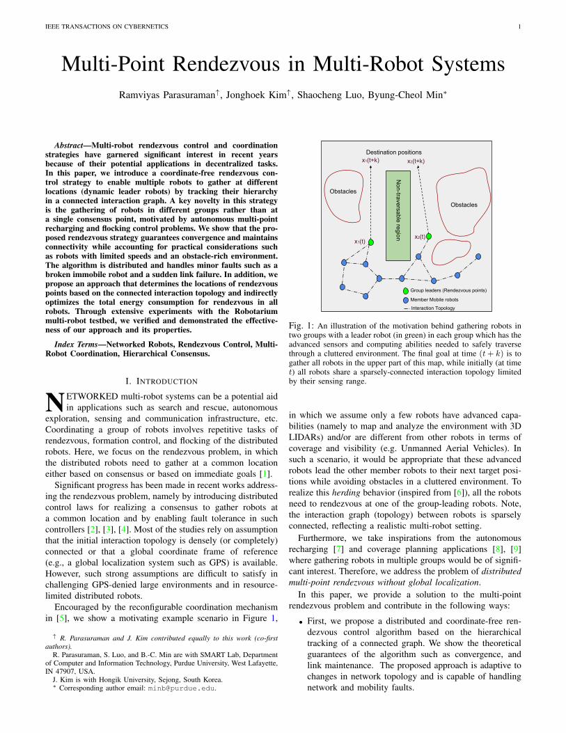
Fig. 1: An illustration of the motivation behind gathering robots intwo groups with a leader robot (in green) in each group which has theadvanced sensors and computing abilities needed to safely traversethrough a cluttered environment. The final goal at time (t+ k) is togather all robots in the upper part of this map, while initially (at timet) all robots share a sparsely-connected interaction topology limitedby their sensing range.
in which we assume only a few robots have advanced capa-bilities (namely to map and analyze the environment with 3DLIDARs) and/or are different from other robots in terms ofcoverage and visibility (e.g. Unmanned Aerial Vehicles). Insuch a scenario, it would be appropriate that these advancedrobots lead the other member robots to their next target posi-tions while avoiding obstacles in a cluttered environment. Torealize this herding behavior (inspired from [6]), all the robotsneed to rendezvous at one of the group-leading robots. Note,the interaction graph (topology) between robots is sparselyconnected, reflecting a realistic multi-robot setting.
Furthermore, we take inspirations from the autonomousrecharging [7] and coverage planning applications [8], [9]where gathering robots in multiple groups would be of signifi-cant interest. Therefore, we address the problem of distributedmulti-point rendezvous without global localization.
In this paper, we provide a solution to the multi-pointrendezvous problem and contribute in the following ways:
• First, we propose a distributed and coordinate-free ren-dezvous control algorithm based on the hierarchicaltracking of a connected graph. We show the theoreticalguarantees of the algorithm such as convergence, andlink maintenance. The proposed approach is adaptive tochanges in network topology and is capable of handlingnetwork and mobility faults.

IEEE TRANSACTIONS ON CYBERNETICS 2
• Secondly, we extend the above algorithm to performrendezvous at multiple points (leader robots). We alsopropose to choose the leaders in each group by optimizingthe distance traveled to realize the rendezvous task.
• Finally, we demonstrate the proposed algorithm in termsof scalability, efficiency, robustness to failures, and herd-ing along with its dynamic nature through extensive simu-lation experiments in the Robotarium multi-robot testbed[10]. To validate the performance of our hierarchicaltracking algorithm, we compare it against two algorithmsavailable in the literature: the standard consensus in [11]and the circumcenter-based consensus in [12].
The paper is organized as follows. In Sec. II, we analyzethe literature and show how we depart from others. Sec. IIIprovides some background on graph theory, assumptions, anddefinitions. Specifically, the multi-point rendezvous problemis formulated in Sec. III-C. Then in Sec. IV, we introducethe proposed algorithm to realize a multi-point rendezvous ofrobots with limited speeds. We present the experiments andresults in Sec. V and conclude the paper in Sec. VI.
II. RELATED WORK
Distributed rendezvous control laws have been well-studiedin the literature [4], [13].Ando et al. [12] proposed a con-trol law to drive a robot towards the circumcenter of therelative positions of all neighboring robots, thereby achievingrendezvous in a distributed manner. In [14], a decentralizedcontrol is proposed that preserves global connectivity byidentifying and limiting control to critical robots that risk beingdisconnected from the global interaction graph. The authors of[15] presented a distributed method for navigating a team ofrobots in formation through static and dynamic obstacles byintegrating the local and global motion planners.
Rendezvous control laws can be classified depending onthe sensing modality used: 1) coordinate-based (using relativepositions) [4], [12]; or 2) bearings-only or range-only (forexample using vision sensors) [3], [16]. Although the abovemethods are able to perform rendezvous efficiently, they havehigh sensing costs because the robots need to keep track of thecoordinates or bearings of all their neighbors in every iteration.Thus, in this paper, we aim to minimize the sensing load ofeach robot by tracking only one of the neighboring robots(designated as its parent robot) using a hierarchical graph-tracking algorithm that is compatible with both coordinate-and bearing-based local movement controllers.
Fault-tolerant rendezvous control methods are also proposedin the literature to enable multiple robots rendezvous evenin the presence of some unidentified faulty robots [2], [17].Note that [2] required a densely connected initial graph and[17] assumed that the probabilities associated to robot failuresare available to realize stochastic optimal control strategiestolerant to faults in the system. However, we do not makesuch assumptions and we find that there is a need for anefficient rendezvous algorithm that can handle both dense andsparse graphs, which is addressed by our proposed hierarchicaltracking approach. In practice, the network topology changesin the event of faulty robots and the proposed algorithm iscapable of handling such changes in the network graph.
Inspired by the graph-based approaches in applicationssuch as multi-robot recharging [7], Leader-Follower tactics[18], and herding in groups [6], [19], [20], we propose aunique strategy to achieve multi-point rendezvous by optimallyselecting leader robots (to reduce the combined traversaldistance of each robot while obeying certain bounds) andassigning other mobile robots to one of the leader robots astheir rendezvous points. In addition, a leader robot can freelymaneuver to perform its own task as long as it is able tomaintain connectivity with its group members. In this way, ourcontrol algorithm is flexible and suitable for realistic scenarioswhere a robot has multiple tasks to perform. As far as weknow, we are the first to introduce multiple rendezvous pointsand intentionally rendezvousing in different groups.
Additionally, literature studies [21] suggested that loco-motion is the main contributor to energy consumption inlarger robots (the longer a robot travels, the higher the energyconsumed). In [22], [23], rendezvous control laws includedoptimization of motion energy, whereas in our work weminimize the distance traveled by all robots (similar to [24]).Thus, the proposed optimization (grouping) strategy indirectlyoptimizes energy consumed during the rendezvous task.
Multi-group rendezvous is first studied in [25], where atheoretically sound approach based on Glowworm SwarmOptimization (GSO) is proposed to localize and rendezvousat multiple peaks of a multi-modal source profile. The robotssplit into multiple groups by following the neighbors withthe highest luciferin value of the sensed objective functionat spatially distributed locations of the robots. However, itfundamentally differs from our work in terms of a sensingstrategy and the goal of rendezvous. In [25], the rendezvoushappens because all the robots in the group aim to reach theposition of the local optimum of a correlated objective functionof a physical process in the field (e.g., temperature, radiation,etc.), whereas in our work, the robots split and rendezvous atthe dynamic leader robots following the network graph withdistance (energy) optimization and herding goals without de-pending on sensing/measurement of a global physical process.
We depart from existing related work in two important ways.First, we introduce a novel strategy for rendezvous in multiplegroups and with dynamic rendezvous points, whereas worksin the literature focused on either a static consensus pointor rendezvous at multiple pre-determined locations. Second,distributed controllers typically use a network graph withouta leader robot for achieving consensus (rendezvous) amongmultiple robots. In such scenarios, meeting points are decidedby the algorithm and the dynamics and spatial distribution ofall robots in the network. However, in our work, we employa hierarchical tracking algorithm using a rooted tree (leader-based rendezvous). Here, meeting points are decided by thedynamics of the leader robots and are not affected by howother non-leader agents are spread out in the space.
Moreover, the presence of dynamic moving leader robotsenables practical applications such as herding and multi-point recharging, which is a key novelty of the proposedsolution. The advantages of the proposed solution in fault-tolerant rendezvous and multi-point herding applications aredemonstrated in Sec. V-G and Sec. V-F, respectively.

IEEE TRANSACTIONS ON CYBERNETICS 3
III. BACKGROUND
This section reviews conventions and definitions used ingraph theory, introduces the assumptions and definitions used,and formalizes the problem statement.
A. Graph Theory
We provide some general notations used in graph theory[26]. Let A = (V,E,W ) denote a undirected weighted graphwith vertex set V and edge set E. Each edge, say e ∈ Eis weighted by a non-negative value and is defined by thematrix W : [wij ]. Two vertices are connected if there is apath between the two vertices, {(i, j) ∈ E |j ∈ Ni}, whereNi represents the neighbors set for robot i. A subgraph of Ainduced by a set of vertices S ⊆ V is the graph (S,ES ,WS),where ES = {(i, j) ∈ E : i, j ∈ S}. We assume that the graphA is symmetric (wij = wji), there is no self-loop or repetitionsof edges (wii = 0), and A is bidirectional (i ∈ Nj ↔ j ∈ Ni).
Tree: Assuming the graph is simple, non-cyclic, wedefine a rooted tree T = (VT , ET ,WT ) where one of thevertices is designated as the root, and every vertex in thetree has a hierarchical structure and establishes a parent-childrelationship with its neighboring vertices. We use the followingterms to define elements of a tree: p(u) denotes the parentrobot of u, c(u) denotes the children set of u, and R(u)denotes the root node of the tree containing the node u. Aleaf in a tree is of the lowest hierarchy (it has no child nodec(uleaf ) = ∅). A shortest-path tree rooted at a vertex v ∈ Vin the graph A is a minimum spanning tree T of A.
B. Assumptions and Definitions
We consider a set of N mobile robots in a 2D workspacewith their positions denoted as qi = [xi, yi]
T ∈ R2. We usethe Single Integrator model to describe their dynamics1.
qi(t) = vi(t), i ∈ V = [1, ...., N ] (1)
where vi(t) ∈ R2 denotes the velocity control input for roboti at time instant t. We define the following definitions andassumptions that will be used in this work.
First, we presume that there is no global localization orcoordinate reference system available, and the robots can onlyuse their local sensors to detect and identify neighboringrobots. Each robot is equipped with local onboard sensors toestimate the relative positions or bearings of the neighboringrobots. We presume that the maximum speed of any robot uis bounded by Sm (‖qu‖ ≤ Sm).
Let us define SR as the maximum sensing range of thelocal sensor, thus resulting in a SR-disk proximity graph [27].Let us define SSRu as the Safe Sensing Range of a robotu beyond which the robot movement may greatly affect thesensing capabilities. SSRu = kSR, k ≤ 1. This limit is usedto let the robots freely maneuver as long as the neighbors arewithin its SSR.
1Without losing generality, the problem can be extended to Double Inte-grator and higher order dynamics. Also, the problem can be adapted to higherdimensions for use in aerial and underwater vehicles.
We say that a robot detects another robot (using range orbearing sensors such as RADAR, LIDAR, SONAR, etc.) whenthe relative distance between the two robots is within SR.We say that a robot meets or merges into another robot whenthe distance between the two robots is less than ε � SR, asmall positive threshold accounting for physical proximity andkinematic constraints. We say that two robots are neighborsif and only if two robots detect each other as we assumea bidirectional graph. Generally, range or bearing sensorsrequire line of sight with the target objects for accuratemeasurements.Therefore, we assume that there is a collision-free path (i.e., no obstacles blocking the line of sight) inevery edge. Nevertheless, this constraint can be overcomeby integrating an obstacle avoidance algorithm at the localcontroller of the robot.
Let A(k) = (VA(k), EA(k),WA(k)) denote the connectivity(proximity) graph at time step k. Each vertex in A(k) isassociated to each robot, and each edge (i, j) in A(k) impliesthat two robots associated to i and j are neighbors. Eachedge in A(k) is weighted as follows. The weight of eachedge, say (i, j) ∈ EA(k), is directly proportional to thedistance between the two robots connected by the edge,wij(k) ∝ ‖qi(k)− qj(k)‖, where qi and qj are the positionsof the robots i and j respectively.
A graph is said to be connected if there is a path (sequenceof connected edges with finite total weight) between every pairof distinct vertices. A collection of graphs is jointly connectedif the union of the set of vertices and edges across all thegraphs remains connected. We assume that the initial graphA(0) is a connected graph.
C. Problem StatementWe consider the problem where the robots are needed to
assemble (rendezvous) into M groups, where the number ofrendezvous points (one for each group) is fixed and prede-termined. Let us assign M robots as the leader (root) robotsof each group. The subset representing the leader robots isdenoted as D ⊆ V . Let Dm ∈ D denote the leader robot ofthe mth group (m ∈ [1, 2, ...,M ]). Let U = V − D denotethe subset of robots that are not leader robots. Each robot inU is assigned one leader robot from D. We use the notationui to represent an arbitrary robot i. Let R(ui) ∈ D denote theleader robot assigned to a robot ui ∈ U .
Objective: The objective of the rendezvous algorithm isto assemble all robots in U to their assigned leader robots inD, i.e., when lim
t→∞‖qui
− qR(ui)‖ = 0, ∀ui ∈ U .
IV. MULTI-POINT RENDEZVOUS STRATEGY
First, a connectivity graph A(k) is built in a distributedmanner with each robot sharing information with its neighborrobots (Sec. IV-A). Then, assuming that the number of groups(M ) is fixed, we assign every robot (in U ) a leader robot(from D) and decompose A(k) into M shortest-path treesusing the method proposed in Sec. IV-B. The rendezvouscontrol algorithm described in Sec. IV-C is applied to eachtree separately (and simultaneously). Finally, we also proposea method to optionally choose the best leader robots from apool of leader robot candidates (Sec. IV-D).

IEEE TRANSACTIONS ON CYBERNETICS 4
Algorithm 1: Distributed Algorithm for Building a GlobalConnectivity Graph A
for every robot ui ∈ V doInit Li,−1 ← ∅ and Li,0 ← Ni (local neighbor lists);c = 0;repeat
Step 1. Get the unique changes in the local neighborlist Li as Li,c = Li,c − Li,c−1;
Step 2. Send Li,c to all uj ∈ Ni;Step 3. Receive Lj,c from all uj ∈ Ni;Step 4. Li,c+1 = Li,c + Lj,c for all uj ∈ Ni;c = c+ 1;
until Li converges (to global list L);Build the global graph A from the converged list Li;
A. Building the Connectivity Graph in a Distributed MannerTo initiate our rendezvous strategy in a distributed fashion,
every robot uses its local sensors to sense neighboring robotsand creates a local neighbor set (list) Li. Each robot thenshares its list with neighbors and constructs, using a distributedalgorithm (Algorithm 1), global connectivity graph A fromthe accumulated list L, which contains nodes and edges forall robots in the network. Algorithm 1 is inspired by thedistributed consensus algorithm in [15].
To illustrate Algorithm 1, let us consider an undirectedcyclic graph with three robots a, b, and c. L of this graphis the accumulation of the three unordered lists by individualrobots: La = {b, c, wab, wac}, Lb = {a, c, wba, wbc}, andLc = {a, b, wca, wcb}. The weights wij for each edge can beobtained from robot’s range sensors, if available. Otherwise,equal weights are presumed.
In Algorithm 1, Ni denotes the neighbor set of a robot i.The convergence to a global list L (hence the graph A) atevery robot is obtained in a maximum of D(A) iterations (i.e.,c ≤ D(A)), where D(A) is the diameter of a connected graphA (the number of nodes along the shortest path from one nodeto its farthest node in the graph A). Thus, Li,D(A) = L ∀i ∈ V ,which can be proved by following an approach similar to theProposition 1 of [15]. Therefore, we omit the proof here.
The worst-case computation cost of the Algorithm 1 de-pends on the graph diameter D(A) and the maximum numberof neighbors for each robot. From [28], we deduce that thegraph diameter is upper bounded by (N−1)
K , where K indicatesthe K-connectedness of the graph. Therefore, the algorithm isscalable because the number of robots in the system is signif-icantly lower than the number of edges and can efficientlybe managed in practical applications. Also, compared to asparse graph (e.g., a path graph), dense graph (e.g., a completegraph) has a lower diameter but a higher number of neighbors.Thus, both the communication and computation workloads arebalanced in terms of density of the graph.
Note that the Algorithm 1 is called only in cases of changesin the network topology and the graph A(k) is dynamicallyupdated according to the changes in the local sensor informa-tion (for instance, a robot detected a new neighbor).
B. Creating Multiple GroupsLet us presume that the set of leader robots D is selected (or
pre-known) depending on their capabilities such as advanced
sensing systems, recharging stations, etc. Alternatively, theleader robots can be chosen from a given graph A(k) using theproposed method in Sec. IV-D, which optimizes the maximumtraversal distance by any robots in the rendezvous process.
Since our objective is to gather all robots to their leaderrobots with the least amount of time and energy, we assigneach robot ui ∈ U a leader robot R(ui) ∈ D by optimizingthe following objective function:
R(ui) = argminDm∈D
dA(k)(ui, Dm). (2)
Here, the function dA(k)(ui, uj) represents the shortest pathdistance (sum of weights for all edges in the shortest pathconnecting them) between ui and uj in the graph A(k) usingDijkstra’s algorithm [29].
Using the initial graph A(0), the robots are grouped togetherto form M sub-graphs Am = (Vm, Em,Wm), where each sub-graph contains nodes, which satisfy the condition:
ui ∈ Vm ⇐⇒ R(ui) = Dm,∀ui ∈ V. (3)
Note the sub-graphs can be dynamically reconstructed asthe graph evolves with A(k), but we consider a special case inwhich the graph is split only initially to reduce computationalload. On the other hand, each sub-graph is dynamically up-dated based on local changes in the sub-graph (Am = Am(k)).
Using the sub-graphs Am, we construct M shortest-pathtrees Tm = (Vm, ETm ,WTm) with root nodes as Dm byoptimizing the distance cost (using weights WTm
) from eachnode to the root node. Each node ui in a tree is assigneda parent p(ui) and children (if any) c(ui). Nodes withoutany children are the leaf nodes (see Sec. III-A). Convertingthe sub-graphs into tree structures significantly reduces thenumber of edges from (potentially) |ETm
| = O(|Vm|2) to|ETm
| = |Vm|−1 resulting in higher computational efficiency.
C. Hierarchical Rendezvous Algorithm
We propose an efficient hierarchical rendezvous algorithmthat enables every robot in the tree Tm to rendezvous at itsroot Dm. Algorithm 2 shows the procedure of the hierarchicalrendezvous that runs iteratively until rendezvous is completed.
The proposed algorithm works as follows. The controlapplied to each robot is to move along the shortest path to theroot robot in Tm. All non-root robots start to move towardstheir immediate parents in the tree hierarchy towards their rootnode. The robot that has at least one child (non-leaf nodes)can move towards its immediate parent only if all its childrenare within a safe sensing range SSRu. Else, it stays and waitsfor its children until they all reach its SSR. After reachingtheir immediate parents, the robots will change their parent tothe parent of their parents p(u) ← p(p(u)) by updating theedges of the tree (by removing the link (u, p(u)) and addingthe link (u, p(p(u))) in tree Tm). This also ensures that thelist of children in the parent nodes is updated accordingly(c(p(u)) = c(p(u))− u, c(p(p(u))) = c(p(p(u))) + u).
Furthermore, as per Algorithm 2, a parent robot u canmove only when all its immediate children are within a SSRudistance from u. Suppose that a child of u, say v, is initiallyfarther than SSRu from u and arrives at u later than other

IEEE TRANSACTIONS ON CYBERNETICS 5
Algorithm 2: Hierarchical Rendezvous Control Algorithmfor every tree Tm
repeatif there is a change in connection/mobility status then
Update Am and the shortest-path tree Tm;
for u ∈ Vm ← every robot in Tm doqu = 0 (default state);if u = Dm (root node - leader robot) then
if ‖qu − qj‖ ≤ SSRu, ∀j ∈ c(u) then‖qu‖ ≥ 0 (qu is not restricted. e.g., Herding);
if u 6= Dm AND a leaf node thenqu = (qp(u) − qu) (4)
if ‖qu − qp(u)‖ < ε thenUpdate the parent of u: p(u)← p(p(u));
if u 6= Dm AND a parent node thenif ‖qu − qj‖ ≤ SSRu, ∀j ∈ c(u) then
Apply controller in Eq. (4);if ‖qu − qp(u)‖ < ε then
Update the parent of u: p(u)← p(p(u));
Bounding qu = min(Sm, ‖qu‖)qu‖qu‖
;
until ‖qu − qDm‖ ≤ ε ∀u ∈ Vm;
children of u. In this case, only the parent robot u waits forv, while the other children of u keep moving toward u andsubsequently will update their parent from u to p(u).
Below, we discuss the theoretical guarantees and the keyproperties of the proposed algorithm. We first prove that therobots in each tree Tm converge to (rendezvous at) theirleader robots Dm (effectively guaranteeing the solution to theproblem described in Sec. III-C).
Theorem 1. For every sub-graph Am (tree Tm), all the robotsin Vm converge to Dm using Algorithm 2, provided that theinitial graph A(0) is a connected graph and over a finitetime interval between two successive iterations [k, k + 1], thegraph Am(k, k+1) = ∪τ∈{k,k+1}(VAm(τ), EAm(τ)) is jointlyconnected.
Proof. We prove convergence and global stability using Lya-punov analysis for discrete control systems. Let us considerthe Lyapunov-like candidate function
V =∑i∈Vm
‖qp(i) − qi‖, (5)
where p(i) represents the parent node of node i in the treeTm. For the control in (4), the equilibrium point qeq = qDm
is the position of the root node, where qu = 0 ∀u ∈ U . It isclear that V = 0 if and only if every robot in Vm merges intoDm, which is the top-most parent in the tree Tm. Therefore,V > 0 ∀qu 6= qeq , and V = 0 ⇐⇒ qu = qeq ∀u ∈ U ,implying V is positive definite. The time derivative of V is,
V =∑i∈Vm
(qp(i) − qi)T
‖qp(i) − qi‖(qp(i) − qi). (6)
As per Algorithm 2, the parent node waits until all thechildren are within its SSRu. i.e., qp(i) = 0. This is alsothe case when the nodes are in the close vicinity of the
equilibrium, where the root node is the parent for all the nodes,and for the rendezvous case, qDm
= 0. Therefore,
V = −∑i∈Vm
(qp(i) − qi)T
‖qp(i) − qi‖qi, (7)
V = − 1
Smq2i ≤ 0. (8)
Hence, we show that the Lyapunov candidate function isnegative semidefinite, proving stability of the nonlinear systemin the sense of Lyapunov. Note, for the control in (4), V = 0only when all the nodes are within ε distance from the rootnode. When the parent and child are within SSRu, then bothparent and child apply the same control of moving towardtheir parents (but not in opposite direction). Therefore, V ≤ 0still holds. Finally, the system converges to the invariance setwhere V = 0, according to LaSalle invariance principle [30].
Although the graph Am is time-varying (switching topol-ogy), changes between iterations do not introduce discontinu-ities because of the condition that the graph is jointly con-nected between any two finite time intervals (periodic) [31],[19]. Maintenance of connectivity is addressed in Theorem 2.
Also, in our assumption (Sec. III-B), two robots meet (ormerge into) each other when they are very close ‖qi−qj‖ ≤ ε.As soon as a robot meet its parent, it re-assigns its parent to thehigher-order parent in the tree. This can induce a jump in V(a discontinuous decrease in V). However, the number of suchjumps is limited by the total number of robots in the system,which is finite. Therefore, these discontinuities do not affectthe convergence of the system. This concludes the proof.
Next, we show that the proposed algorithm guarantees thateach robot maintains connectivity with their parents and theirchildren during the rendezvous process.
Theorem 2. (Connectivity maintenance) Using Algorithm 2,the tree Tm remains connected during the rendezvous process.
Proof. To prove this, we show that every robot is sensed by atleast one robot during a maneuver. Let P (u,Dm) denote thepath taken by a robot u to reach its root Dm. Let pu denoteany of the parent robots (including Dm) that u pursues inits hierarchy following the path P (u,Dm). As per the tree,pu also shares the subset of the path of u, and pu beginsmoving towards its parent only if u is within the SSRu, i.e.,pu moves along the path P (pu,Dm) = P (u,Dm)−P (u, pu).Maintaining u within the SSRu of pu ensures that u is alwayssensed by pu (because SSR ≤ SR), therefore u and pumaintain their connectivity even when both are moving. Thisalso includes the case where pu = Dm is freely maneuvering(to execute herding behavior for example).
In cases where pu cannot move (say, because one of its childis not yet within its SSR), then u passes pu and continuesto pursue the higher-level parent ppu (if pu 6= Dm). In thiscase, u will sense ppu because when u meets pu (whendTm
(u, pu) ≤ ε), u and ppu can both be sensed by each other(dTm(u, ppu) ≤ SR). Since every robot is sensed by at leastone robot, mutual protection can be provided for every robot.Thus, u always maintains connectivity with any of the robotsin its path, hence Am (and tree Tm) is always connected.

IEEE TRANSACTIONS ON CYBERNETICS 6
Theorem 3. The anticipated traversal distance of any robotin Tm following Algorithm 2 until it rendezvous is boundedby the shortest path distance dTm(u,Dm).
Proof. Trivial. The tree Tm is the shortest path tree generatedfrom the sub-graph Am. Thus, the path followed by any robotu during the rendezvous process has a length (total distance)of dTm
(u,Dm).
As per the algorithm, each robot senses and pursues it’sparent node. This can be realized by using relative coordinates[11] or bearings [3] of the parent node.
Remark 1. This implies that the proposed algorithm iscoordinate-free and that the robots do not require a globalcoordinate reference or a global localization system.
Note, in our proposed method, obstacle detection and avoid-ance are handled using the local motion controllers of eachrobot (e.g., [32], [33]) during the phase when the robot movestoward its parent as per Algorithm 2. For sake of brevity, we donot analyze the impact of obstacle avoidance on the behaviorof the proposed multi-point rendezvous method. Convergencewill not be affected as long as the obstacles do not completelydisrupt the sensing capabilities of the robot.
Algorithm 2 is designed to handle the case where a com-munication or the interaction topology is dynamically updated(see Sec. IV-A). It is also designed to handle cases of mobilityor communication faults if the fault is detected and identifiedby at least one robot in the system2 (using the method in[34] for example). In such cases, we re-generate the tree Tmusing the updated graph A(k), and the algorithm works on theupdated tree structure.
Remark 2. This implies that the proposed algorithm can workeven in cases of intermittent connectivity and is tolerant tocommunication or mobility related faults.
The root node of every tree is the rendezvous point ofthe sub-group. The root robots Dm in every tree can freelymaneuver as long as all of their immediate children are withinthe SSRDm
(which is a requirement in Theorem 2 to safelymaintain connectivity with their children).
Remark 3. This implies that the proposed algorithm enablesherding behavior guided by the moving leader (root) robots.
Herding here means that the leader robots guide (herd) theirgroup member robots to the final destination positions [6]either during or after the rendezvous process. Note herdingis different from flocking behavior [35] in which all the robotstend to travel in the same direction keeping their formation.
D. Choosing Leader Robots (Rendezvous Points)
In situations where the leader robots are not known orcannot be chosen based on their capabilities3, we present a
2Note our assumption that the faults are identifiable is different from theassumption used in the Tverberg partition based method [2] which can workeven under the presence of unidentified faults, however at the cost of alimitation that a densely connected initial graph A(0) is required.
3An example of such situation is a homogeneous multi-robot system whereall the robots have equal capabilities.
simple and efficient strategy to optimally choose M leaderrobots (rendezvous points) among all the robots in the network.
In multi-robot applications, it is highly desirable to achieverendezvous in the shortest possible time. This goal can be metif we minimize the (anticipated) maximum distance traveledby any robot during the rendezvous process. This limits thetime and energy consumed by any robot in the system. Note,Theorem 3 provides the bound for this maximum distancewhich impacts the time to rendezvous. Therefore, we searchthe optimal leader robots set D from the set V in the initialgraph A(0) by minimizing the following cost function
C(D) = max∀Dm∈D
max∀u∈Vm
dA(k)(u,Dm), (9)
subjected to the following constraints
Lm ≤ |Vm| ≤ Um (10)
where |Vm| denotes the number of robots in the group in whichDm is the leader after applying the grouping algorithm inSec. IV-B. Lm and Um are the bounds for |Vm|. Also, con-sidering a distance bound TD, we have additional constraintas follows.
dA(0)(u,R(u)) ≤ TD, ∀u ∈ (V −D). (11)
The first constraint balances the sizes of all M groupswhereas the second constraint restricts the maximum distancetraveled by any robot in the rendezvous task.
Since the cost function to be minimized (Eq. 9) is non-smooth and non-differentiable, standard analytical methodssuch as Integer Linear Programming (ILP) cannot be applieddirectly. Also, the number of robots in the pool of potentialcandidates of leader robots Vpl among all the robots is verylimited in practice (|Vpl| << N ). Thus, the scalability of thesearch solution is not an issue.
Therefore, we propose Brute-Force search solution whichis simple and efficient to solve the following optimizationproblem:
D∗ = argminD∈Dpl
C(D) (12)
where Dpl =
(VplM
)is the set of all candidate solutions for
D, and D∗ is the optimal set of leader robots which willeventually be used in Algorithm 2.
Using Algorithm 1, each robot builds the global graph Ain a distributed manner. This results in every robot sharingan identical graph A. Then, D∗ is calculated using the initialgraph A(0) as per Algorithm 3. Note that while this optimiza-tion can be performed distributively by applying Algorithm 3locally on every robot, doing so is only needed in the initialstage; therefore, we assume that a central agent performs thisparticular optimization and shares the resulting D∗.
In Algorithm 3, the initial connectivity graph A(0) is usedto generate a table Tb, which is an N by N matrix thatpresents the all-path shortest-path distances between everyrobot pair, with each row representing a source robot. Forexample, the element of Tb at the ith row and jth columnpresents the shortest-path distance between two robots ui anduj . By definition, Tb(i, i) is zero.

IEEE TRANSACTIONS ON CYBERNETICS 7
Algorithm 3: Calculate D∗
Data: Graph A from Algorithm 1Generate table Tb using Dijkstra’s algorithm on A;cost = inf ;for D ∈ List of M leaders chosen from MCN selection cases
doif D satisfies the constraints (10) and (11) then
costo ← C(D) from Eq. (9);if costo < cost then
cost← costo;D∗ ← D;
We vary the source robot among all robots and derivethe shortest path from the selected source to every otherrobot using Dijkstra’s algorithm [36]. The time complexityof Dijkstra’s algorithm is O(N2), so varying over N sourcerobots is O(N3). Suppose that Tb is built. Then, we arbitrarilychoose M source robots out of N robots. There are MCNselection cases in total. For each case, the chosen M sourcerobots are the rendezvous robots. In other words, each caserepresents a situation where M rendezvous robots are selected.We derive the cost function in (9) associated with each case,and search for the case that returns the minimum cost whileobeying the constraints in (10) and (11).
The complexity of Algorithm 3 will scale up with thenumber of edges in the graph A(k). Thus, the proposedsolution is effective in cases where A(k) is a sparse graph.Addressing this problem for dense graphs is an avenue forfuture work.
V. EXPERIMENTAL EVALUATION
In this section, we first present the experiment setup, evalu-ation metrics, and list the experiment scenarios considered inthe experiments. Then, we describe each of the scenarios alongwith a discussion of the achieved results. Note the experimentresults of all the scenarios are available in the video4.
A. Experiment Setup
To validate the proposed method, we conducted extensivesimulation experiments in the Robotarium MATLAB platform[10] which is a free multi-robot and swarm robotics experi-ment testbed recently made available by Georgia Tech [10].We chose the Robotarium because it provides testbeds forboth simulations and hardware experiments with the GRITSbotrobots [37] using the same software implementation.
Robotarium has an 2D arena of size 3m × 3m, in whichup to 15 robots (currently supported) can be used in hardwareexperiments; however, in the simulations, the number of robotsare not restricted. The GRITSbot robot (size 4cm × 4cm)exhibits unicycle dynamics, but it can be also controlled viasingle integrator dynamics. The coordinates of all the robotscan be accessed in every iteration during the experiments. Thecommon parameter settings are SR = 0.8m, Sm = 0.1m/s,ε = 0.1m, SSR = 0.5SR, max number of iterationskmax = 1000. The Robotarium Robotarium updates the poseat a maximum of 30 Hz.
4 Youtube link: https://youtu.be/uaiCnw79Sb8
B. Evaluation Metrics
We used the following three metrics to measure the perfor-mance of the rendezvous task in our experiments.
1) Lyapunov candidate function (Convergence):
L =∑ui∈U
‖qui− qR(ui)
‖. (13)
2) Total distance traveled by all robots (Distance):
Dsum =∑ui∈U
kmax∑k=1
‖qui(k + 1)− qui
(k)‖. (14)
3) Number of iterations (kstop ≤ kmax) to reach the follow-ing stop condition:
Stop at kstop if ‖qui− qR(ui)
‖ ≤ ε, ∀ui ∈ U. (15)
These metrics show how fast the algorithm converges toachieve rendezvous, and how long the robots travel beforeachieving rendezvous.
C. Experiment scenarios
We consider the following five scenarios to verify anddemonstrate the effectiveness and the performance of theproposed rendezvous strategy:• Scenario 1 - Single-point rendezvous• Scenario 2 - Multi-point rendezvous• Scenario 3 - Multi-point rendezvous with identifiable
faults and/or detectable communication failures• Scenario 4 - Herding with multi-point rendezvous• Scenario 5 - Optimization of rendezvous pointsUsing Scenario 1 (Sec. V-D), we verify the effectiveness
of the Algorithm 2 in terms of convergence and scalabilityand analyze how it compares to the state-of-the-art consensusalgorithms. We verify in Scenario 2 (Sec. V-E) the multi-pointcapability of our proposed hierarchical rendezvous algorithm.Then, in Scenario 3 (Sec. V-F) we examine how the proposedrendezvous algorithm performs under mobility faults and in-termittent connectivity. This scenario is also used to validatewhether the algorithm guarantees convergence of non-faultyrobots. Scenario 4 (Sec. V-G) exemplifies an effective herdingbehavior facilitated by the multi-point rendezvous algorithm.Finally, in Scenario 5 (Sec. V-H) the advantages of choosingoptimal leader robots are observed.
D. Scenario 1 - Single-point rendezvous
In this scenario, we verify the convergence property of theAlgorithm 2 when M = 1 under the cases N = [10, 20, 30].Additionally, this scenario is also used to compare the per-formance of our hierarchical tracking algorithm against twoalgorithms available in the literature: the standard coordinatesbased consensus algorithm in [11] and the circumcenter basedconsensus algorithm in [12]. The robot initial positions andthe respective initial graphs A are shown in Fig. 2.
Since the consensus algorithms are designed to convergeat a consensus point determined by the geometric distributionof the robots, we adapted them to rendezvous at a specific

IEEE TRANSACTIONS ON CYBERNETICS 8
-1 -0.5 0 0.5 1 1.5
x(m)
-1.2
-1
-0.8
-0.6
-0.4
-0.2
0
0.2
0.4
0.6
0.8y(m
)
1
2
3
4
5
6
7
8
9
10
-1.5 -1 -0.5 0 0.5 1 1.5
x(m)
-1.5
-1
-0.5
0
0.5
1
1.5
y(m
)
1
2
3
4
5
6
7
8
9
10
11
12
13
14
15
16
17
18
19
20
-1.5 -1 -0.5 0 0.5 1 1.5
x(m)
-1.5
-1
-0.5
0
0.5
1
1.5
y(m
)
12
3
4
5
6
7
8
9
10
1112
13
14
15
16
17
18
19
20
21
22
23
24
25
26
27
28
29
30
Fig. 2: The top figures show the initial positions of the robots used in the experiments with N = 10 (left), N = 20 (center),and N = 30 (right). The respective initial network/interaction topologies (undirected graphs) are shown in the bottom figures.
root robot node (instead of a consensus point) by assigning azero velocity to the root robot. However, the consequence ofsuch adaptation is that these algorithms perform slower andthe robots trajectories may be significantly changed during thecourse of the process. To the best of our knowledge, there is norendezvous control algorithm in the literature that converges toa specific root node, hence this adaptation to the state-of-the-art consensus algorithms is deemed necessary for comparison.
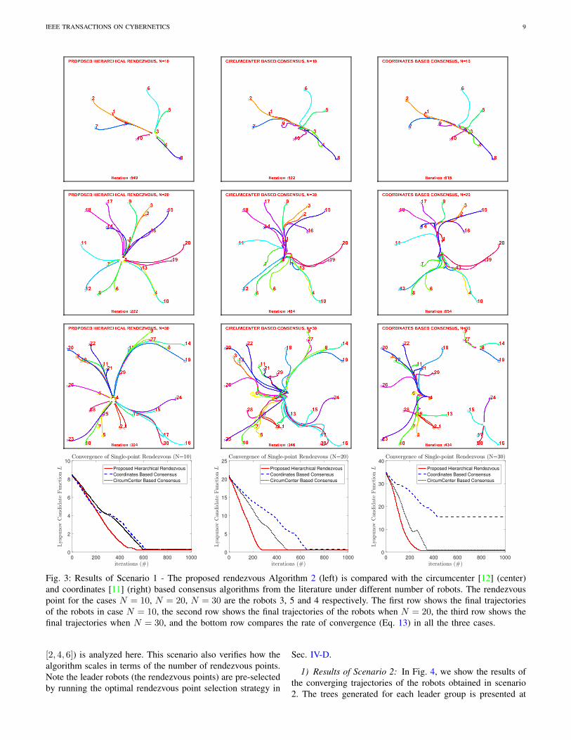
1) Results of Scenario 1: Figure 3 presents the resultingtrajectories and the convergence plots (Eq. 13) of the threealgorithms compared in Scenario 1 for the different numberof robots. The results for the metrics of the sum of distancetraveled (Eq. 2) and the number of iterations to reach ren-dezvous stop condition (Eq. 15) are provided in Table I.
Algorithm Metric N = 10 N = 20 N = 30
Ours Dsum(m) 9.31 23.11 39.45kstop (#) 549 292 304
CircumCenter [12] Dsum(m) 12.76 30.69 58.7kstop (#) 592 484 346
Coordinates [11] Dsum(m) 13.99 32.5 46.9kstop (#) 615 654 -
TABLE I: Results of the metrics E and kstop in Scenario 1.
From Table I, we can notice that the proposed strategy out-performed the other algorithms in terms of shorter combinedtravel distance by all robots to achieve rendezvous (Dsum) andlower number of iterations required to converge (kstop).
It can be seen from Fig. 3 that the trajectory of the proposedhierarchical rendezvous algorithm is smoother than the othertwo algorithms compared here. This can be attributed tothe fact that the consensus-based algorithms almost achievedrendezvous at a common point (based on their distribution)as they are originally supposed to, and then continued to
rendezvous at the desired leader robot due to the adaptationmentioned before.
In terms of convergence rate, the hierarchical algorithm hadthe fastest convergence in general and continued to increasewhen the number of robots (N ) is increased. Note, when thenumber of robots is increased, the number of neighboringnodes for each robot is larger. This resulted in more efficientmovements observed by the Robotarium pose updates (fasterconvergence) when N is larger.
Although the kstop metric showed a significant decreasewhen N is increased from 10 to 20, it did not show sucha decrease when N is increased to 30 from 20. Perhaps, thisis because of the current Robotarium design which is expectedto scale up to 100 robots in future.
Similar to circumcenter based algorithm [12], our algo-rithm guarantees connectivity maintenance resulting in theconnected graph at the end. On contrary, the coordinates basedconsensus algorithm [11] does not guarantee connectivitymaintenance, and thus resulted in a disconnected graph for thecase N = 30. In fact, we implemented an improved versionof this coordinate-based algorithm from [4] where potentialfields (weights) are used to ensure connectivity maintenance.Although the improved algorithm guaranteed connectivity, theconvergence rate of [4] was significantly lower than [11]mainly because the control inputs in [4] are weighted basedon the distance between the robots which resulted in slowermovement when the robots are close to achieving rendezvous.Thus, we chose not to present the results of the consensusalgorithm in [4].
E. Scenario 2 - Multi-point rendezvousThe efficiency of the multi-point rendezvous algorithm for
N = 30 with a different number of rendezvous points (M =
IEEE TRANSACTIONS ON CYBERNETICS 9
0 200 400 600 800 1000
iterations (#)
0
2
4
6
8
10
Lyapunov
Candidate
FunctionL
Convergence of Single-point Rendezvous (N=10)
Proposed Hierarchical Rendezvous
Coordinates Based Consensus
CircumCenter Based Consensus
0 200 400 600 800 1000
iterations (#)
0
5
10
15
20
25
Lyapunov
Candidate
FunctionL
Convergence of Single-point Rendezvous (N=20)
Proposed Hierarchical Rendezvous
Coordinates Based Consensus
CircumCenter Based Consensus
0 200 400 600 800 1000
iterations (#)
0
10
20
30
40
Lyapunov
Candidate
FunctionL
Convergence of Single-point Rendezvous (N=30)
Proposed Hierarchical Rendezvous
Coordinates Based Consensus
CircumCenter Based Consensus
Fig. 3: Results of Scenario 1 - The proposed rendezvous Algorithm 2 (left) is compared with the circumcenter [12] (center)and coordinates [11] (right) based consensus algorithms from the literature under different number of robots. The rendezvouspoint for the cases N = 10, N = 20, N = 30 are the robots 3, 5 and 4 respectively. The first row shows the final trajectoriesof the robots in case N = 10, the second row shows the final trajectories of the robots when N = 20, the third row shows thefinal trajectories when N = 30, and the bottom row compares the rate of convergence (Eq. 13) in all the three cases.
[2, 4, 6]) is analyzed here. This scenario also verifies how thealgorithm scales in terms of the number of rendezvous points.Note the leader robots (the rendezvous points) are pre-selectedby running the optimal rendezvous point selection strategy in
Sec. IV-D.
1) Results of Scenario 2: In Fig. 4, we show the results ofthe converging trajectories of the robots obtained in scenario2. The trees generated for each leader group is presented at

IEEE TRANSACTIONS ON CYBERNETICS 10
M=2 M=3 M=4
Fig. 4: Results of Scenario 2 - Multi-point rendezvous (N = 30) with M = 2 (left), M = 3 (center), and M = 4 (right). Theinitial trees (created using the approach in Sec. IV-B) rooted at their leader robots of each group are depicted in the bottomrow.
0 200 400 600 800 1000
iterations (#)
0
5
10
15
20
25
30
Lyapunov
Candidate
FunctionL
Convergence of the Multi-point Rendezvous (N=30)
M=2
M=3
M=4
Fig. 5: Multi-point rendezvous convergence in Scenario 2.
the bottom row of the Fig. 4. In the case of M = 2, therobots were split into two groups of size 17 and 13 robots.When M = 3, the number of robots in each group were 16,8, and 6. For M = 4, the groups had 10, 8, 6, and 6 robots.Although it is possible to experiment with higher M values,it will not present meaningful results in terms of convergenceor efficiency. It can be easily seen that the trajectories of therobots were not a straight path to their leader robots becausethe algorithm routes the non-root robots to track their parentsin the hierarchical tree.
Table II shows the metrics Dsum and kstop in scenario 2.The robots traveled shorter due to the fact that the number ofrobots in each group is reduced when M is increased.
The resulting tree graphs in Fig. 4 show that the groupingalgorithm in Sec. IV-B led to evenly distributed subgroupsfrom the initial graph A(0) (see the bottom right graph ofFig. 2). Also, see that within every subgraph, the robotsconverged with smooth trajectories toward their leader robots(rendezvous nodes).
The convergence of the algorithm under different M valuesare shown in Fig. 5. It can be seen that the higher the numberof leaders (M ), the faster the convergence due to the fact thateach group runs the algorithm in parallel and the average sizeof the group is reduced when M is increased.
F. Scenario 3 - Multi-point rendezvous with faults
This scenario is designed to verify the robustness of theproposed rendezvous strategy under identified communicationand mobility faults. The number of robots and rendezvouspoints in this scenario is N = 30 and M = 2. The
Metric M = 2 M = 3 M = 4Dsum(m) 29.51 21.81 15.62kstop (#) 199 182 131
TABLE II: Results for the Algorithm 2 in Scenario 2.

IEEE TRANSACTIONS ON CYBERNETICS 11
Fig. 6: Robot trajectories in Scenario 3 - Multi-point ren-dezvous with faulty robots. The robots 9 and 25 are simulatedwith mobility faults (at t = 25 and t = 50 respectively)whereas the robots 30 and 11 are simulated with communi-cation faults (at t = 25 and t = 50 respectively). The robot11 regained its connection at t = 100 (hence, it could achieverendezvous with its root robot 18).
0 50 100 150 200 250
iterations (#)
0
5
10
15
20
25
30
Lyapunov
Candidate
FunctionL
Multi-point Rendezvous with Faults (N=30, M=2)
At t=25, the drop in L is due to:
Robot 9 - mobility fault;
Robot 30 - disconnected.
At t=50, the drop in L is due to:
Robot 25 - mobility fault;
Robot 11 - disconnected.
At t=100, L increases because
Robot 11 is reconnected.
Fig. 7: Convergence plot of Scenario 3. The Lyapunov functionL in Eq. 13 is calculated only for non-faulty robots. Notethe sudden drop and raise in the L value due to the injected(simulated) faults. The non-faulty robots achieved rendezvous.
corresponding initial graph is shown in Fig. 2 (right) and thecorresponding trees are shown in Fig. 4 (left, case M = 2).
At arbitrary instances, randomly selected robots (except theroot nodes) are injected with mobility faults (by setting theirvelocities to follow a random sinusoidal trajectory followingthe strategy in [2]) or with communication faults (by removingthe robot in the graph to simulate disconnection for instance).
Specifically, the following faults situations are simulated:
• At iteration t = 25+, robots 9 and 30 are respectivelyinjected with a mobility fault and a communication fault(sudden disconnection).
• At t = 50+, the robot 25 faces a mobility fault and therobot 11 faces a communication disruption (to simulatean intermittent connectivity).
• At t = 100+, the robot 11 regains connectivity with itsneighbors (e.g., using a reactive motion planner [38]).
1) Results of Scenario 3: Figures 6 and 7 show the resultsof the trajectories and convergence plot in Scenario 3. It canbe seen from Fig. 6 that the robot 30 was participating in therendezvous process initially, but as soon as it got disconnected,it did not move. On the other hand, the robot 11 (intermittentconnectivity) lost its connection and did not move initially,nevertheless, it completed rendezvous process as soon as it gotreconnected. Similarly, the robots 9 and 25 (mobility faults)got removed from the tree as soon as they became faulty andidentified as faulty robots. The other non-faulty robots adaptedtheir trajectories accordingly to achieve rendezvous.
These behaviors can also be observed from the convergenceof the Lyapunov candidate function (with only non-faultyrobots) shown in Fig. 7 where the faults are tolerated by theproposed rendezvous algorithm.
G. Scenario 4 - Herding with multi-point rendezvous
In this scenario, we show how the proposed algorithmenables herding behavior by aiding the movement of ren-dezvous (leader) robots to their specific goal positions in thearena during or after achieving rendezvous. We simulate thisscenario with N = 20 and M = 2 (see the center graphin Fig. 2). The leader robots are chosen as 1 and 13 whichare capable to reach their final destinations (1, 0) and (0,−1)(indicated as ‘stars’) respectively in the environment.
We show two cases where the herding starts immediatelyafter rendezvous process is initialized (at t = 1, first case)and the herding starts in between the rendezvous process (att = 100, second case). We do not show the case where theherding starts after the rendezvous is completed (when the stopcondition is reached), because in this case both the rendezvousand the herding tasks are disconnected.
1) Results of Scenario 4: Figure 8 presents the evolutionof trajectories in Scenario 4. In Fig. 8, the initial robotpositions are denoted by hollow circles for member robotsand solid circles for the leader robots. The final destinationsare indicated as stars. The herding behavior is achieved bysetting a position controller of the leader robots to their finaldestination positions. Nonetheless, they can move toward theirdestinations (only) as long as they can see their immediatechildren within the SSR. Thus, the rendezvous process is notdisrupted during the herding movement.
It can be seen that in both cases the robots achievedrendezvous while herding to the final destination by the leaderrobots. At t = 100, the trajectories of the robots indicate thatthe robots perform both rendezvous and herding in the firstcase while the robots perform rendezvous only in the secondcase. At t = 200, the herding is almost completed in thefirst case whereas it took up to t = 300 iterations to completeherding in the second case. This is because the herding startedlater in the second case compared to the first case.
It’s worth noting that the same algorithm proposed inSec.IV-C executed both rendezvous and herding simultane-ously. This is done by setting the velocities of the leaderrobots to zero (for rendezvous) and to follow a trajectory to adestination position (for herding).

IEEE TRANSACTIONS ON CYBERNETICS 12
(a) t = 100. (b) t = 200. (c) t = 300.
Fig. 8: Scenario 4 - Evolution of trajectories at iterations t = 100, t = 200, and t = 300. The robot herding stared at t = 1 inthe first case (top row) and at t = 100 in the second case (bottom row). The leader robots in both cases are 1 and 13 and thedestination position for the leader robots while herding their group members are (1, 0) and (0,−1) respectively. The earlierthe herding started, the faster the final destination was reached while simultaneously performing the rendezvous.
H. Scenario 5 - Multi-point rendezvous with optimization ofrendezvous points
Through this scenario, we explicate the advantages ofchoosing optimal rendezvous points (selecting leader robots)using the strategy in Sec. IV-D. To better show this scenario,we need the higher number of robots, and hence we choseN = 60. Given the limited number of robots in Robotarium,we created our own simulation setup in MATLAB replicatingpoint dynamics in a cluttered (obstacle-rich) environment ofsize 50m× 50m with N = 60 and M = 2.
In the simulation of Scenario 5, we applied a constraint onsensing ability such that a robot can sense another robot onlyif there is a line of sight path between them (obstacle-freemovements). The simulation settings for this scenario are ε =0.05m, SR = 10m, SSR = ε, Sm = 0.3m/s. Other parametersettings are the same as that of the previous scenarios. Thesampling rate at which the algorithm runs is 10 Hz. A sampletrial is shown in Fig. 9 in which the distribution of robotsalong with their connectivity links are captured.
As with the previous scenario, we do not implement anobstacle avoidance algorithm in robot movements. However, todeal with the obstacles, we applied a constraint on the sensingability. A robot can sense another robot only if there is aline of sight path between these two robots, i.e., if there areno obstacles on the way. The parameters settings ensure thatall the robots follow obstacle-free paths while tracking theirhierarchical parents to rendezvous at its root node.
We compare the performance of optimal rendezvous pointsagainst randomly selected rendezvous points in a Monte-Carlo
0 10 20 30 40 500
5
10
15
20
25
30
35
40
45
50
x
y
Fig. 9: Scenario 5 - An example trial showing the randomdeployment of initial positions of all robots (indicated as bluecircles) in an obstacle-rich environment. The green dotted linesrepresent the connectivity links between the robots. The redcurves indicate the boundaries of the obstacles.
simulation with 50 trials (each with random initial positionsforming a connected graph). The settings for the optimizationconstraints are chosen as Lm = 6 and Um = 45 while TD isunconstrained to enable longer feasible paths to the leaders.
1) Results of Scenario 5: Figure 10 shows the convergenceplot in Scenario 5 with the L values averaged over theiterations. The Table III shows the results of the evaluationmetrics in Scenario 5 - Energy E (Eq. 2) and the number ofiterations to reach the stop condition kstop (Eq. 15) - theirmean and standard deviation (STD) over all the trials.

IEEE TRANSACTIONS ON CYBERNETICS 13
Selection of Leader Robots Dsum (m) kstop (#)Mean STD Mean STD
Random (Monte-Carlo) 1747 584 2316 751Optimized (Sec. IV-D) 1160 134 1234 129
TABLE III: Results of the metrics E and kstop in Scenario 5.
0 1000 2000 3000 4000 5000
iterations (#)
0
500
1000
1500
Lyapunov
Candidate
functionL
Convergence of the Multi-point Rendezvous (N=60)
RandomSelect
OptimalSearch
Fig. 10: Convergence plot in Scenario 5 - Comparison of L(averaged over 50 iterations) in case of optimally selectedleader robots using the proposed algorithm in Sec. IV-Dagainst randomly selected leader robots.
It can be observed from Fig. 10 that the simulations withoptimized leader robots resulted in a significantly faster con-vergence compared to that of the simulations with randomlyselected leader robots. It is important to note that the selectionof leader robots may be due to the robot capabilities in someapplications where such optimization is not possible. Never-theless, in applications where it is feasible to optimize theleader robots, the proposed strategy can be greatly beneficial.
From the Table III, we can see that the mean and standarddeviation of evaluation metrics (E and kmax) are considerablybetter when the optimal search method in Sec. IV-D is usedcompared to the case where the optimal search method isnot used. This means that the rendezvous algorithm quicklyachieved rendezvous (the robots traveled shorter distances intotal) because of having optimal rendezvous points as a resultof the optimization. This is an indirect reduction of total energyconsumption of the robots because the robot energy costs aredominated by the movements (locomotion energy) [21].
Although the optimization algorithm (Sec. IV-D) is scalablefor sparse graphs, we are exploiting other methods such asLinear Programming to choose optimal leader robots from aninitial dense graph as part of our future work.
VI. CONCLUSIONS
In this paper, we propose a novel coordinate-free multi-point rendezvous strategy and a new, efficient hierarchicalrendezvous algorithm to gather robots in different groups. Thisis a step towards achieving autonomous multi-point rechargingand solving coordinated multi-point flocking control problems.
Through extensive simulation experiments (with the Robo-tarium multi-robot testbed), we demonstrated the effectivenessof the proposed algorithm along with its properties suchas guaranteed convergence, connectivity maintenance, andtolerance to intermittent connectivity and identifiable mobility
faults. We have also shown that the proposed algorithm out-performed the state-of-the-art consensus controllers in termsof convergence rate and capability.
Moreover, we introduced and validated an application ofmulti-group herding of multi-agent systems, aided by theproposed multi-point rendezvous algorithm. Finally, we exper-imentally verified a simple and effective optimization strategyfor selecting rendezvous points (leader robots) that allowsthe robots to achieve faster convergence and travel shorterdistances. The experiments and results are summarized in thevideo available at https://youtu.be/uaiCnw79Sb8.
Future works include devising a failure detection systemaided by the hierarchical tree structure to detect a robot’s com-munication or mobility failure by its immediate parent robotusing a heartbeat communication mechanism and analyzingthe history of changes in the graph for example.
ACKNOWLEDGMENT
This work was partially supported through the “NSF Centerfor Robots and Sensors for the Human Well-Being, NSF GrantNo. 1439717”.
REFERENCES
[1] J. Lin, A. Morse, and B. Anderson, “The multi-agent rendezvousproblem. an extended summary,” in Cooperative Control. Springer,2005, pp. 257–289.
[2] H. Park and S. A. Hutchinson, “Fault-tolerant rendezvous of multirobotsystems,” IEEE Transactions on Robotics, vol. 33, no. 3, pp. 565–582,June 2017.
[3] R. Zheng and D. Sun, “Multirobot rendezvous with bearing-only orrange-only measurements,” Robotics and Biomimetics, vol. 1, no. 1, p. 4,Oct 2014.
[4] M. Zavlanos, M. Egerstedt, and G. Pappas, “Graph theoretic connectivitycontrol of mobile robot networks,” Proceedings of the IEEE, vol. 99,no. 9, pp. 1525–1540, 2011.
[5] C. Vrohidis, P. Vlantis, C. P. Bechlioulis, and K. J. Kyriakopoulos,“Reconfigurable multi-robot coordination with guaranteed convergencein obstacle cluttered environments under local communication,” Au-tonomous Robots, pp. 1–21, 2017.
[6] A. Pierson and M. Schwager, “Bio-inspired non-cooperative multi-robotherding,” in 2015 IEEE International Conference on Robotics andAutomation (ICRA), May 2015, pp. 1843–1849.
[7] N. Mathew, S. L. Smith, and S. L. Waslander, “A graph-based approachto multi-robot rendezvous for recharging in persistent tasks,” in Roboticsand Automation (ICRA), 2013 IEEE International Conference on. IEEE,2013, pp. 3497–3502.
[8] B. Li, B. Moridian, and N. Mahmoudian, “Underwater multi-robotpersistent area coverage mission planning,” in OCEANS 2016 MTS/IEEEMonterey, Sept 2016, pp. 1–6.
[9] M. Meghjani, S. Manjanna, and G. Dudek, “Multi-target rendezvoussearch,” in 2016 IEEE/RSJ International Conference on IntelligentRobots and Systems (IROS), Oct 2016, pp. 2596–2603.
[10] D. Pickem, P. Glotfelter, L. Wang, M. Mote, A. Ames, E. Feron, andM. Egerstedt, “The robotarium: A remotely accessible swarm roboticsresearch testbed,” in Robotics and Automation (ICRA), 2017 IEEEInternational Conference on. IEEE, 2017, pp. 1699–1706.
[11] A. Jadbabaie, J. Lin, and A. S. Morse, “Coordination of groups of mobileautonomous agents using nearest neighbor rules,” IEEE Transactions onautomatic control, vol. 48, no. 6, pp. 988–1001, 2003.
[12] H. Ando, Y. Oasa, I. Suzuki, and M. Yamashita, “Distributed mem-oryless point convergence algorithm for mobile robots with limitedvisibility,” IEEE Transactions on Robotics and Automation, vol. 15,no. 5, pp. 818–828, 1999.
[13] D. V. Dimarogonas and K. J. Kyriakopoulos, “On the rendezvousproblem for multiple nonholonomic agents,” IEEE Transactions onAutomatic Control, vol. 52, no. 5, pp. 916–922, May 2007.
[14] L. Sabattini, C. Secchi, N. Chopra, and A. Gasparri, “Distributed controlof multirobot systems with global connectivity maintenance,” IEEETransactions on Robotics, vol. 29, no. 5, pp. 1326 – 1332, 2013.

IEEE TRANSACTIONS ON CYBERNETICS 14
[15] J. Alonso-Mora, E. Montijano, M. Schwager, and D. Rus, “Distributedmulti-robot formation control among obstacles: A geometric and opti-mization approach with consensus,” in Robotics and Automation (ICRA),2016 IEEE International Conference on. IEEE, 2016, pp. 5356–5363.
[16] J. Yu, S. M. LaValle, and D. Liberzon, “Rendezvous without coordi-nates,” IEEE Transactions on Automatic Control, vol. 57, no. 2, pp.421–434, Feb 2012.
[17] H. Park and S. Hutchinson, “Robust rendezvous for multi-robot systemwith random node failures: an optimization approach,” AutonomousRobots, Feb 2018.
[18] M. Ji, A. Muhammad, and M. Egerstedt, “Leader-based multi-agentcoordination: controllability and optimal control,” in 2006 AmericanControl Conference, June 2006.
[19] Z. Chen and H. T. Zhang, “Analysis of joint connectivity condition formultiagents with boundary constraints,” IEEE Transactions on Cyber-netics, vol. 43, no. 2, pp. 437–444, April 2013.
[20] H.-T. Zhang, Z. Chen, and M.-C. Fan, “Collaborative control of multive-hicle systems in diverse motion patterns,” IEEE Transactions on ControlSystems Technology, vol. 24, no. 4, pp. 1488–1494, 2016.
[21] R. Parasuraman, K. Kershaw, P. Pagala, and M. Ferre, “Model basedon-line energy prediction system for semi-autonomous mobile robots,”in Intelligent Systems, Modelling and Simulation (ISMS), 2014 5thInternational Conference on. IEEE, 2014, pp. 411–416.
[22] T. Setter and M. Egerstedt, “Energy-constrained coordination of multi-robot teams,” IEEE Transactions on Control Systems Technology, 2016.
[23] P. Lin, W. Ren, H. Wang, and U. M. Al-Saggaf, “Multiagent rendezvouswith shortest distance to convex regions with empty intersection: Algo-rithms and experiments,” IEEE Transactions on Cybernetics, vol. PP,no. 99, pp. 1–9, 2018.
[24] P. Zebrowski, Y. Litus, and R. T. Vaughan, “Energy efficient robotrendezvous,” in Fourth Canadian Conference on Computer and RobotVision, Canada, 2007.
[25] K. Krishnanand and D. Ghose, “Theoretical foundations for rendezvousof glowworm-inspired agent swarms at multiple locations,” Robotics andAutonomous Systems, vol. 56(7), pp. 549 – 569, 2008.
[26] B. W. Douglas, Introduction to Graph Theory, 2nd ed. Illinois, USA:Prentice Hall, 2001.
[27] F. Bullo, J. Cortes, and S. Martınez, Distributed Control of RoboticNetworks, ser. Applied Mathematics Series. Princeton University Press,2009, electronically available at http://coordinationbook.info.
[28] “Graphs of maximum diameter,” Discrete Mathematics, vol. 102, no. 2,pp. 121 – 141, 1992.
[29] S. M. Lavalle, Planning Algorithms. Cambridge University Press, 2006.[30] J. P. La Salle, The stability of dynamical systems. SIAM, 1976.[31] E. Montijano and C. Sagues, “Robotic networks and the consensus
problem,” in Distributed Consensus with Visual Perception in Multi-Robot Systems. Springer, 2015, pp. 9–19.
[32] J. Kim, “Cooperative exploration and networking while preservingcollision avoidance,” IEEE transactions on cybernetics, vol. 47, no. 12,pp. 4038–4048, 2017.
[33] B.-C. Min, R. Parasuraman, S. Lee, J.-W. Jung, and E. T. Matson, “Adirectional antenna based leader–follower relay system for end-to-endrobot communications,” Robotics and Autonomous Systems, vol. 101,pp. 57–73, 2018.
[34] F. Arrichiello, A. Marino, and F. Pierri, “Distributed fault detection andrecovery for networked robots,” in IEEE/RSJ International Conferenceon Intelligent Robots and Systems, Sept 2014, pp. 3734–3739.
[35] R. Vaughan, N. Sumpter, J. Henderson, A. Frost, and S. Cameron,“Experiments in automatic flock control,” Robotics and autonomoussystems, vol. 31, no. 1, pp. 109–117, 2000.
[36] S. Pettie, “A new approach to all-pairs shortest paths on real-weightedgraphs,” Theoretical Computer Science, vol. 312, no. 1, pp. 47 – 74,2004, automata, Languages and Programming.
[37] D. Pickem, M. Lee, and M. Egerstedt, “The gritsbot in its natural habitat-a multi-robot testbed,” in Robotics and Automation (ICRA), 2015 IEEEInternational Conference on. IEEE, 2015, pp. 4062–4067.
[38] S. Caccamo, R. Parasuraman, L. Freda, M. Gianni, and P. gren, “Rcamp:A resilient communication-aware motion planner for mobile robotswith autonomous repair of wireless connectivity,” in 2017 IEEE/RSJInternational Conference on Intelligent Robots and Systems (IROS), Sept2017, pp. 2010–2017.
Ramviyas Parasuraman is currently a postdoctoralresearcher at Purdue University. His research mainlyfocuses on networked robot systems, rescue robotsand teleoperation. From 2014 to 2016, Dr. Parasur-aman held a postdoctoral research position at KTHRoyal Institute of Technology, where he worked intwo European projects TRADR and RECONFIG.Previously, he worked at the European Organizationfor Nuclear Research (CERN) as a Marie-CurieFellow from 2011-2014 and received his Ph.D. inRobotics and Automation from Universidad Politc-
nica de Madrid, Spain, in 2014. He received M.Tech from Indian Instituteof Technology Delhi (2010) and B.Engg (2008) from Anna University, India.Dr. Parasuraman serves as a reviewer and a program committee member inseveral journals and conferences in robotics.
Jonghoek Kim is an Assistant Professor in theDepartment of Electrical and Computer Engineeringat Hongik University, Republic of Korea. His re-search is on target tracking, control theory, robotics,multi-agent systems, and optimal estimation. Heworked as a senior researcher at Agency for DefenseDevelopment in Republic of Korea from 2011 to2018. In 2011, he earned a Ph.D. degree co-advisedby Dr. Fumin Zhang and Dr. Magnus Egerstedt atGeorgia Institute of Technology, USA. JonghoekKim received his M.S. in Electrical and Computer
Engineering from Georgia Institute of Technology in 2008 and his B.S. inElectrical and Computer Engineering from Yonsei University, Republic ofKorea in 2006.
Shaocheng Luo is a Ph.D. student in Robotics inthe Department of Computer and Information Tech-nology at Purdue University (West Lafayette). Priorto beginning his Ph.D. program in 2014, Mr. Luoobtained his B.S. degree in Mechanical Engineeringfrom Harbin Institute of Technology, China in 2009,and M.S. degree in Mechatronic Engineering fromZhejiang University, China in 2012. His researchinterests include multi-robot systems, robotic co-ordination control, and wireless communication. Inaddition to pursuing his Ph.D. degree, Mr. Luo has
developed interests in robotic system applications in environmental monitoringand operations and Cyber-Physical Systems.
Byung-Cheol Min is an Assistant Professor in theDepartment of Computer and Information Technol-ogy at Purdue University. He directs the SMARTLab at Purdue University, which performs researchin multi-robot systems, robotic sensor networks,and human-robot interaction with emphasis in fieldrobotics and assistive technology and robotics. From2014 to 2015, prior to his faculty position at PurdueUniversity, Dr. Min held a postdoctoral fellow po-sition at the Robotics Institute of Carnegie MellonUniversity. He received his Ph.D. in Technology with
a specialization in Robotics from Purdue University, West Lafayette, IN USA,in 2014. He received his M.S. degree in Electronics and Radio engineeringin 2010 and B.S. degree in Electronics Engineering in 2008 from Kyung HeeUniversity, Republic of Korea.