Embed Size (px)
DESCRIPTION
User guide on Ansys ICEM
Citation preview

1
Lecture One: Introduction to the
CFD
The basic procedure for CFD simulation
Flow
wall
wall
Preprocessing(1)Geometry definition
(2)Discrization
(3)Physical modeling
(4)Boundary conditions
Simulation(1)Solver definition
(2)solving
Post-processing(1) Plot results
(2) Conclusions

2
Fluent PackagePre-processing
Solving
Post-processing
ICEM
Pre-processing
� Fluid domain definition (Geometry)
� Mesh Generation
� Boundary condition definition

3
Principle of fluid domain definition
Bottom up method:
(1)key points
(2)Lines
(3)Surfaces
(4)Volume(3D)
Geo 1
The domain should
be closed by lines to
form face
Step 1 Step 2
Step 3
Geo 2
Step 1
Step 2
Step 3
Principle of fluid domain definition

4
Step 1Step 2
Step 3
Using Curves
Principle of fluid domain definition
Introduction to the ICEMICEM is a specialized software to create the geometry, mesh
and boundary conditions for Fluent; in the following slices
we will use ICEM for the pre-processing.
From Start menu�
All programs�
Ansys�
Ansys CFD ICEM

5
Problem specification:
Inlet
12cm
14cm
outlet
2cm
1cmP1
P2 P3
1cm
Fluid: Water; 2D problem
The coordinates for the 6 points:
P1: 0, 0.01, 0
P2: 0, 0, 0
P3: 0.02, 0, 0
P4: 0.02, -0.01, 0
P5:0.14, -0.01, 0
P6:0.14, 0.01, 0
Therefore z coordinate is the same
Note: Because the default unit
system in Fluent for length is m, so
in order to make it easy, the length
unit we use in ICEM is assumed to
be m.
P4 P5
P6
strategies � Bottom-up approach:
point � line � surface � volume
Here we use Bottom-up approach, that is from
point ���� line ���� surface

6
Procedure
� Step 1, start the ICEM
From Start menu�
All programs�
Ansys�
Ansys CFD ICEM
Main Window
Main graphic window
Function Tabs
Message window
opensave
Fit the window
Zoom in or out
undoredo
Display
Control Tree

7
Procedure
Point � Line � Surface
� Step 2, choose the proper working directory
all geometry and mesh files will be stored in that directory
File � Change Working Dir…
Choose the directory you want to
save, such as C:/lecture1

8
Step 3 Create the initial points
(1) Choose Geometry tab
(2) Click for creating points,
(4) Click explicit locations
(6) Input x y z coordinates
(7) Click apply for creation
(9) When you finish creation, click
dismiss to quit the panel.
(1)
(2)
(3)
(4)
(5) Choose ‘Create 1 Point’ in the list
(8) Create other points from step 5 to 6
(5)
(6)
(7)
The coordinates for the 6 points:
P1: 0, 0.01, 0 P2: 0, 0,0 P3: 0.02, 0,0 P4: 0.02, -0.01,0
P5:0.14,-0.01,0 P6:0.14, 0.01,0
(3)remain the part name to be GEOM
Click to show points in the whole window,
you can find it in the left corner of toolbar
6 points can be found in the black background
Note: make sure the part name is unique for one geometry, in this
example, when you want to create points and lines , check the part
name to be GEOM, or the name you have given in the beginning.

9
Other operations
(1)enquiry the point information (a) In the toolbar (left corner), left click the third icon to open the list,
then choose location icon
(b) Mouse cursor becomes a cross, move the cursor to one point, and left
click that point
(c) Using middle mouse button to finish
(d) Scrolling middle mouse wheel to zoom in and zoom out
(2) delete the unwanted points
(a) In Geometry tab, choosing delete point icon
(b) In the Delete Point panel, choosing selecting points icon
(c) In the main window, a toolbar appear to help you to choose, and a line of
red text explains how to choose.
Using left button to choose, right button to cancel, middle button to finish
(d) Click apply to delete points, dismiss to quit the panel
If you have deleted one of the 6 points, please create it again.

10
Note: about selection in the main window by mouse
During the selection procedure, the cursor changes the shape to be a cross, a
toolbar appears to help the selection, move mouse to individual icon to see
the hint (waiting for seconds )
A line of red text will show in the bottom
Left button : select several entities in an order, such as p1, p2 , p3, …
Right button: cancel the selection in a reversed order as selection, …p3, p2, p1
Middle button: accept the selection
Note: it may automatically trigger the following function for the
selection, for example, during the line creation, after you select two points, when click middle button, the line will be created, you do not need to click the apply button for creation. Check the output information for the actions done by middle mouse button
Procedure
Point�Line�Surface
11
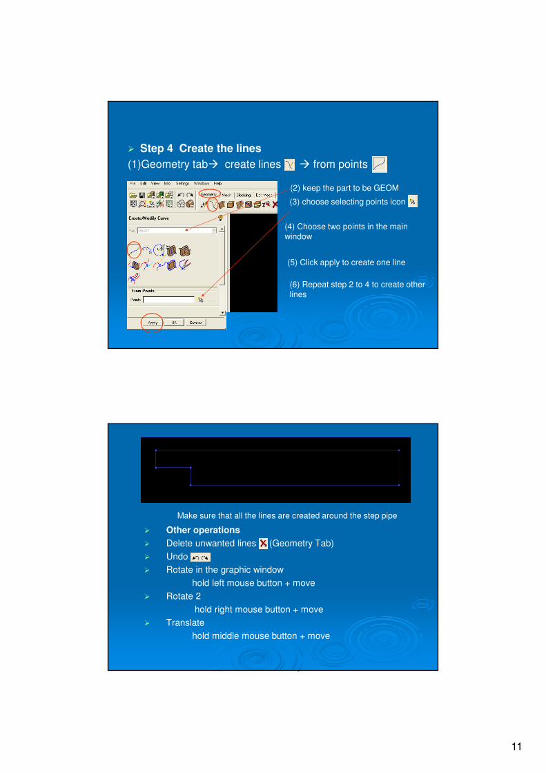
� Step 4 Create the lines
(1)Geometry tab� create lines � from points
(3) choose selecting points icon
(4) Choose two points in the main
window
(5) Click apply to create one line
(6) Repeat step 2 to 4 to create other
lines
(2) keep the part to be GEOM
Make sure that all the lines are created around the step pipe
� Other operations
� Delete unwanted lines (Geometry Tab)
� Undo
� Rotate in the graphic window
hold left mouse button + move
� Rotate 2
hold right mouse button + move
� Translate
hold middle mouse button + move

12
Choosing Front in From view menu to restore the view if the points are
not shown properly
Boundary Definition

13
(a) Where is the fluid region?
(b) What is the type of fluid? Air, water or blood?
(c) Fluid direction, from where and where to go?
(d) Boundaries to constrain the fluid flow, such as wall, symmetry boundary
Computer does not know where is fluid domain, it is
your job to tell it
Fluid domain
Inletoutlet
wall
wall
Inlet:VelocityMass flow ratePressure……
Outlet:VelocityMass flow ratePressure……
Wall:Non-slipSlip……
Check Model Control Tree
Under Parts:
The GEOM is the geometry you have created
Now we need to define inlet, outlet, wall, fluid
domain in GEOM
Fluid domain
Inletoutlet
wall
wall

14
Step 1: Define fluid domain
(a) In Geometry tab, choose Create Body icon
(b) Change the name, usually BODY
(c) Choose Create Material Point
(d) Turn on Centroid of 2 points
(e) Click to define two screen locations
Click left button in
upper and lower walls,
middle mouse button
to accept the selection
Location 1
Location 2
(f) OK to finish
The created body is showed in the main window
Model Control Tree view

15
Step 2: define inlet
(a) At model control tree view, right click Parts
(b) From the menu, select Create Part
The panel for creating part
(c) Change the part name to be Inlet
(d) Select create part by selection
(e) Click select entries
(f) In the main window, select the edge for Inlet
boundary. Left click to select, middle button to accept.
When selected, the line will be highlighted
(h) Check the parts in model control tree view
inlet
INLET will be added. when you turn off inlet, the edge will disappear in the main window, this step can be used to verify the boundary creation
(g) Click Apply

16
Step 3: Create Outlet Boundary
outlet
Model control tree view
Step 4: select the left edges for Wall
Edges for wall boundary

17
Check model control tree view
There are:
GEOM
INLET
OUTLET
WALL
You can turn off to check where those parts are, now GEOM only represents
created points, you can change the name to be points, or leave it
Save the geometry file from File Menu
Mesh: PrincipleDivide the computational domain into small parts,
on which the computation will be performed
Step 1Define the division along the lines
Step 2Divide the region based on the line division
E1 E2 E3
E4 E5 E6
Basic element shape

18
Triangular Mesh
Fine Mesh
Fine meshMore controls on mesh density
Some concerns about the mesh quality
(a) Fine mesh in the region of interest, such as at the step region
(b) Fine mesh near the wall
(c) Fine mesh in the abrupt change of the geometry
……

19
Mesh
Lines � Surface
ANSYS ICEM CFD Blocking provides a projection-based mesh generation
environment where, by default, all block faces between different materials are
projected to the closest CAD surfaces.
Blocking Strategy For Mesh Generation
Block Geometry
edge1 Curve 1edge3
edge2
edge4
Curve 2
Curve 3
Curve 4
The association between Block to the geometry is :
Edge1 � Curve1
Edge2 � Curve2
Edge3 � Curve3
Edge4 � Curve4
The mesh generation in Block will be projected to
the corresponding geometry by defined
association

20
Steps in Blocking Meshing
(a) Create and split blocks, discard unused blocks to capture underlying shape
(b) Associate edges to curves to capture hard features. Move vertices to position
block corners on geometry
(c) Assign mesh sizes such as maximum element size
(d) Automatically generate mesh
(e) Write Output files to the desired solvers.
Blocking strategy in the example
Geometry
(a) Initialize Block
(b) Split block
(c) Delete unnecessary block
(d) Define association between block and geometry
(f) Mesh generation

21
Step 1: Create the blocks
(a) At Blocking tab, choose Create block icon
the Create Block panel will show in the left
(b) Choose BODY from the list
(c) Choose initialize block icon
(d) Choose type to be 2D planar
(e) Apply to finish, dismiss to quit
The Block will be created for the body we just created, the body comes from geometry creation procedure (fluid domain definition, page 28)
This step will automatically create the block
according to the dimension of the created
geometry
Created block( the white lines indicate the existence of block)
output showed in the information window

22
(a) Select Split block from Blocking Tab
Step 2: split block
(b) Choose split blocks icon
(c) All visible to be turned on
(d) Click selecting lines icon
(e) In the main window, left click the top line
in the middle position, a line will be created.
(f) Choose the new created line by left mouse
button and keep holding to move the line to the
step corner
(g) Click middle mouse button to accept the creation
(h) If you want to cancel the creation just right click
Click position
(I) Left click the left line in the middle position, move the created line to the step
corner
Click position
(J) Click OK to finish

23
Step 3: deleted unnecessary block in the left corner
(a) In the Blocking tab choose delete block
(b) Click selecting blocks icon
(c) In the main window choose the left lower corner by
left click, the block will be highlighted.
This one
(d) Middle button to accept, then the block will be deleted
Now only three blocks are left, which are the same locations as the step boundaries
Block 1 Block 2
Block 3

24
Step 4: associate the created block with geometry, a one to one map for
the edges in block and curves in the geometry.
Note: block, edge are logical structure, point, curve, surface, volume are
physical structure of the model. This step also tells comupter the model
region boundary.
(a) Choose associate icon
(b) Choose associate edge to curve
Edge: from block; curve: from GEOM part
(c) Click select edge icon
(d) In the main window to select one line, middle
button to finish the selection
The name for the selected edge
(e) Click select curve icon
(f) In the main window, select one curve (when
selected, the line will be highlighted), the same
location as in step d, middle button to finish the
selectionNote: In step f, when click middle button, ICEM may automatically create the association without clicking Apply
Edge 1Curve 1
Edge 2
Edge 3
Edge 4
Edge 5
Edge 6Edge 7
Curve 2
Curve 3
Curve 4
Curve 5
Therefore the associates are
(1) Edge1 � Curve 1
(2) Edge2 � Curve 2
(3) Edge3 � Curve 3
(4) Edge4 � Curve 4
(5) Edge5 � Curve 4
(6) Edge6 � Curve 5
(7) Edge7 � Curve 5

25
The associations may be verified by selecting Edges >Show Association in the
Display tree. As shown, the green arrows in the display point from an edge to its
associated curve. Nodes and vertices of these edges will project on to the
associated geometry.
Display Tree, in the left side
Right click
In our example, because the edges are the
same locations as the curves, so the
arrows can not be seen.
Step 5: applying mesh parameters
(a) In the blocking tab choose “pre-mesh params” setup
(b)”Choose meshing parameters”
(c) Choose select edge icon
(d) In the main window choose the left edge for
inlet, middle mouse button to accept, the name in
ICEM will be displayed
(e) In the number of nodes, input 20
(f) Spacing 1 and 2 are the minimum space for
each node from the starting point to the ending
point respectively
(g) Ratio 1 and 2 are corresponding ratio of
distance between the nodes for both ends for
nin-uniform mesh distribution
(h) Click apply to accept the change and
back to (c) to choose another edge.

26
Node numbers for all curves
20
20 20
80
40
100
Step 6: Initial Mesh Generation
(a)In the structure tree, open blocking part
(b) Tick pre-mesh box,
(c) A pop-out window shows in the main working
space and choose “yes” to re-compute pre-mesh.
Note: if the pre-mesh box
was on, click it to turn it
off and turn it on again to
re-calculate the mesh.
Pre-mesh will be displayed as this

27
Step 7: Saving the Mesh and Blocking
(a) Save the mesh in unstructured format: Right mouse select Pre-Mesh
and select Convert to Unstruct Mesh to generate the domain file.
Now you have meshes created from pre-
mesh. If you turn off “Pre-Mesh” in
“Blocking”, you will still see meshes in the
model which contains shells and lines.
If you are not happy about the mesh, you can
always delete them by File > Mesh > Close
Mesh. It will delete all meshes in the project, but
“Pre-Mesh” are still there since they are not real
mesh yet.
Check the line element to see the walls.
In a 2D problem, line element acting as surface element in 3D to enclose
the physical domain. Therefore, any broken parts of line element will
cause problem in CFD calculation.
(a) In the structure tree window:
(1) turn off “geometry”
(2) in “mesh”, turn off “shells” and click open “lines”
(3) in “blocking”, turn off every thing except subsets
(4) in “parts”, turn on everything.
you should see a clear boundary of the model where the walls were
defined (including inlet and outlet boundaries)
If you turn off “lines” in blocking, the model should disappear.
(b) If you find gaps in the model wall when “line” is on, you should either
go back to the stage of block definition and start again, or go to “Edit
Mesh” on

28
Edit mesh (need advanced reading, optional)
Edit mesh gives you many options to repair your mesh, but further
readings are needed for the option.
You can generate line meshes under “create element”
In the “create element” you can create some
line meshes in the broken gapes shown in the
previous model. (“Help” file will give your more
details).
Save the project (for restart next time)
(a) If the line element checking is satisfied,
you can save the project.
(b) Select File > Save Project As… and type
in a project name. All files: tetin
(geometry file), blocking and
unstructured mesh will be saved.
(c) You can load project file for continuation or
just geometry file. It is better to save the project
frequently.

29
Step 8: Export mesh
(a) From Output tab choose select solver
(b) From the list select Fluent_V6 for Output Solver
Leave this(c) Click OK to finish setting
Step 9: Save the project and export the mesh
(a) In the Output tab, select
(b) A dialog will prompt out, select Yes for saving
(c) Then a file open dialog will ask
you to select the mesh file(*.uns),
which is the same name as your
project name. Usually the name
provided by this dialog is the right
one, click OK to open

30
(d) Turn on 2D
The example is a 2D problem, leave others to be default
(e) You can change the Output file name
by replacing fluent
(f) Click Done
(g) Go to the working directory, find the mesh file:
fluent.msh or (yourname).msh
(h) Save the mesh file
for next lab session
Summary
Basic Elements for CFD with ICEM:
� Fluid domain geometry definition
� Define parts including boundaries, walls and all parts that you may need to be separated from the general geometry so that can be used in CFD boundary condition and post processing
� Mesh generation (including mesh checking)
� Mesh Export