Embed Size (px)
Citation preview
© 2011 ANSYS, Inc. March 22, 20151 Release 14.0
14. 0 Release
Introduction to ANSYSICEM CFD
Lecture 9 (Optional)Additional Hexa Functions
© 2011 ANSYS, Inc. March 22, 20152 Release 14.0
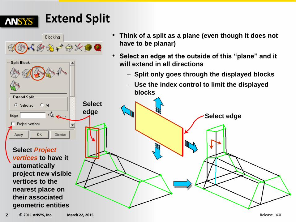
Extend Split• Think of a split as a plane (even though it does not
have to be planar)
• Select an edge at the outside of this “plane” and it
will extend in all directions
– Split only goes through the displayed blocks
– Use the index control to limit the displayed
blocks
Select edge
Select
edge
Select Project
vertices to have it
automatically
project new visible
vertices to the
nearest place on
their associated
geometric entities
© 2011 ANSYS, Inc. March 22, 20153 Release 14.0
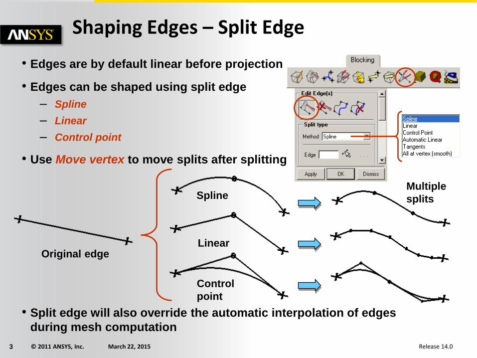
• Edges are by default linear before projection
• Edges can be shaped using split edge
– Spline
– Linear
– Control point
• Use Move vertex to move splits after splitting
• Split edge will also override the automatic interpolation of edges
during mesh computation
Shaping Edges – Split Edge
Spline
Linear
Control
point
Original edge
Multiple
splits
© 2011 ANSYS, Inc. March 22, 20154 Release 14.0
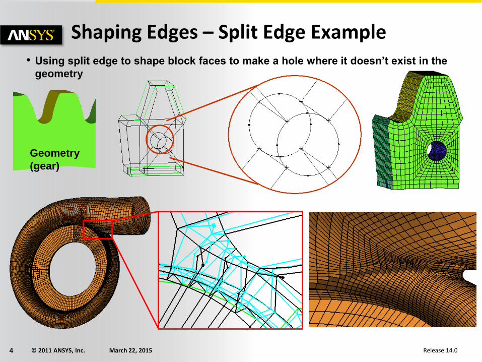
Shaping Edges – Split Edge Example• Using split edge to shape block faces to make a hole where it doesn’t exist in the
geometry
Geometry
(gear)
© 2011 ANSYS, Inc. March 22, 20155 Release 14.0
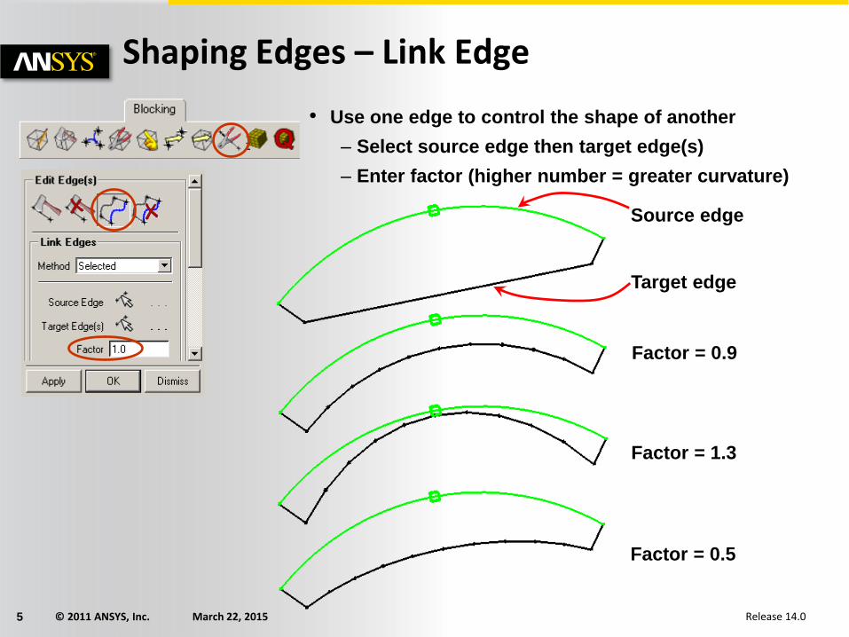
Shaping Edges – Link Edge
• Use one edge to control the shape of another
– Select source edge then target edge(s)
– Enter factor (higher number = greater curvature)
Source edge
Target edge
Factor = 0.9
Factor = 1.3
Factor = 0.5
© 2011 ANSYS, Inc. March 22, 20156 Release 14.0
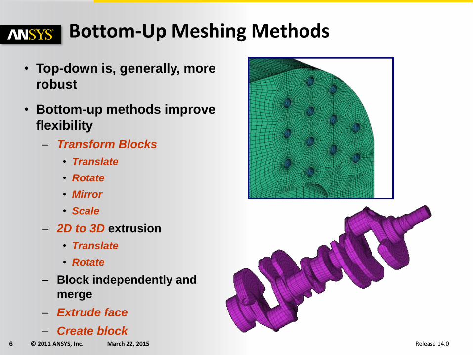
Bottom-Up Meshing Methods
• Top-down is, generally, more
robust
• Bottom-up methods improve
flexibility
– Transform Blocks
• Translate
• Rotate
• Mirror
• Scale
– 2D to 3D extrusion
• Translate
• Rotate
– Block independently and
merge
– Extrude face
– Create block
© 2011 ANSYS, Inc. March 22, 20157 Release 14.0
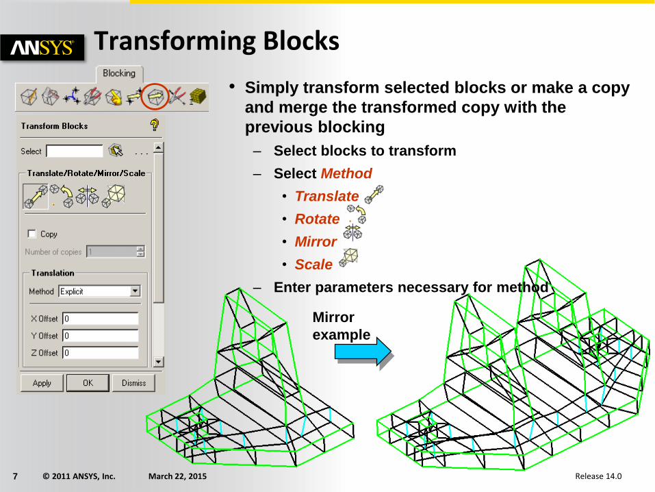
Transforming Blocks
• Simply transform selected blocks or make a copy
and merge the transformed copy with the
previous blocking
– Select blocks to transform
– Select Method
• Translate
• Rotate
• Mirror
• Scale
– Enter parameters necessary for method
Mirror
example
© 2011 ANSYS, Inc. March 22, 20158 Release 14.0
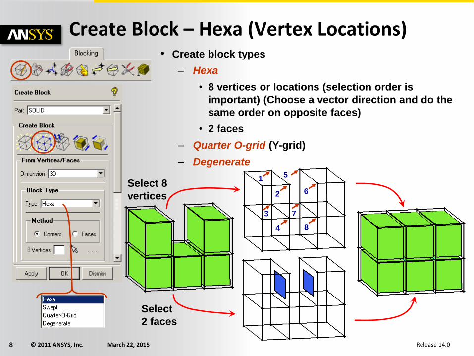
• Create block types
– Hexa
• 8 vertices or locations (selection order is
important) (Choose a vector direction and do the
same order on opposite faces)
• 2 faces
– Quarter O-grid (Y-grid)
– Degenerate
Create Block – Hexa (Vertex Locations)
1
4
3
2
5
6
7
8
Select 8
vertices
Select
2 faces

© 2011 ANSYS, Inc. March 22, 20159 Release 14.0
87
65
4
1
3
Create Block – Hexa (Geometry Locations)
• What if I don’t have 8 vertices to select?
– Select the vertices that you do have
– Press middle mouse button
– Select the rest of the locations on the screen
– The same order must be maintained as before
2
Press
middle
button
© 2011 ANSYS, Inc. March 22, 201510 Release 14.0
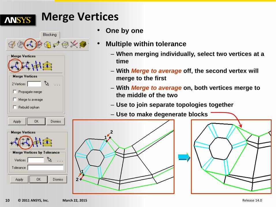
Merge Vertices• One by one
• Multiple within tolerance
– When merging individually, select two vertices at a
time
– With Merge to average off, the second vertex will
merge to the first
– With Merge to average on, both vertices merge to
the middle of the two
– Use to join separate topologies together
– Use to make degenerate blocks
1
2
1
2
© 2011 ANSYS, Inc. March 22, 201511 Release 14.0
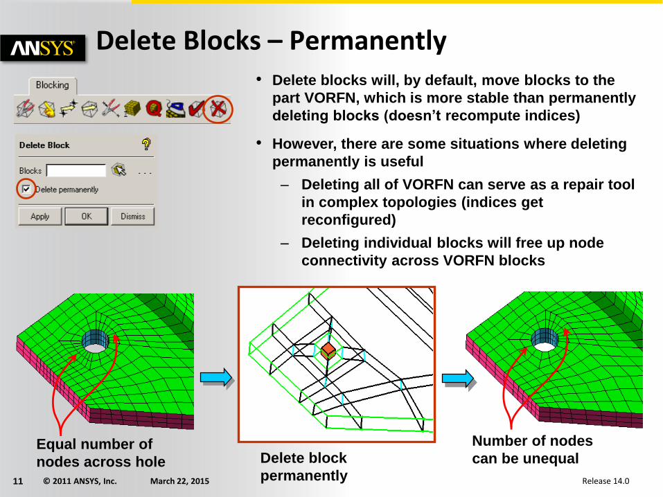
Delete Blocks – Permanently
Equal number of
nodes across hole
Number of nodes
can be unequal
• Delete blocks will, by default, move blocks to the
part VORFN, which is more stable than permanently
deleting blocks (doesn’t recompute indices)
• However, there are some situations where deleting
permanently is useful
– Deleting all of VORFN can serve as a repair tool
in complex topologies (indices get
reconfigured)
– Deleting individual blocks will free up node
connectivity across VORFN blocks
Delete block
permanently

© 2011 ANSYS, Inc. March 22, 201513 Release 14.0
Select
refinement
edge
direction or
select “All”
• Defines integer multipliers of elements across
block interfaces
– Can only be used with certain solvers
– Refine: Factor > 1 (enter integer)
– Coarsen: Factor < 1 (enter fraction – 1/2, 1/3,
etc.)
Refinement
Select
block(s) to
refine within Factor = 1/3
© 2011 ANSYS, Inc. March 22, 201514 Release 14.0
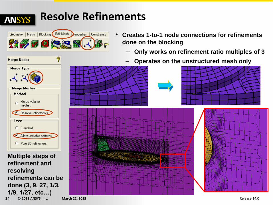
Resolve Refinements
• Creates 1-to-1 node connections for refinements
done on the blocking
– Only works on refinement ratio multiples of 3
– Operates on the unstructured mesh only
Multiple steps of
refinement and
resolving
refinements can be
done (3, 9, 27, 1/3,
1/9, 1/27, etc…)
© 2011 ANSYS, Inc. March 22, 201515 Release 14.0
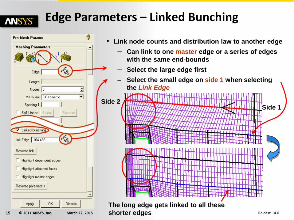
Edge Parameters – Linked Bunching
Side 1Side 2
• Link node counts and distribution law to another edge
– Can link to one master edge or a series of edges
with the same end-bounds
– Select the large edge first
– Select the small edge on side 1 when selecting
the Link Edge
The long edge gets linked to all these
shorter edges
© 2011 ANSYS, Inc. March 22, 201516 Release 14.0
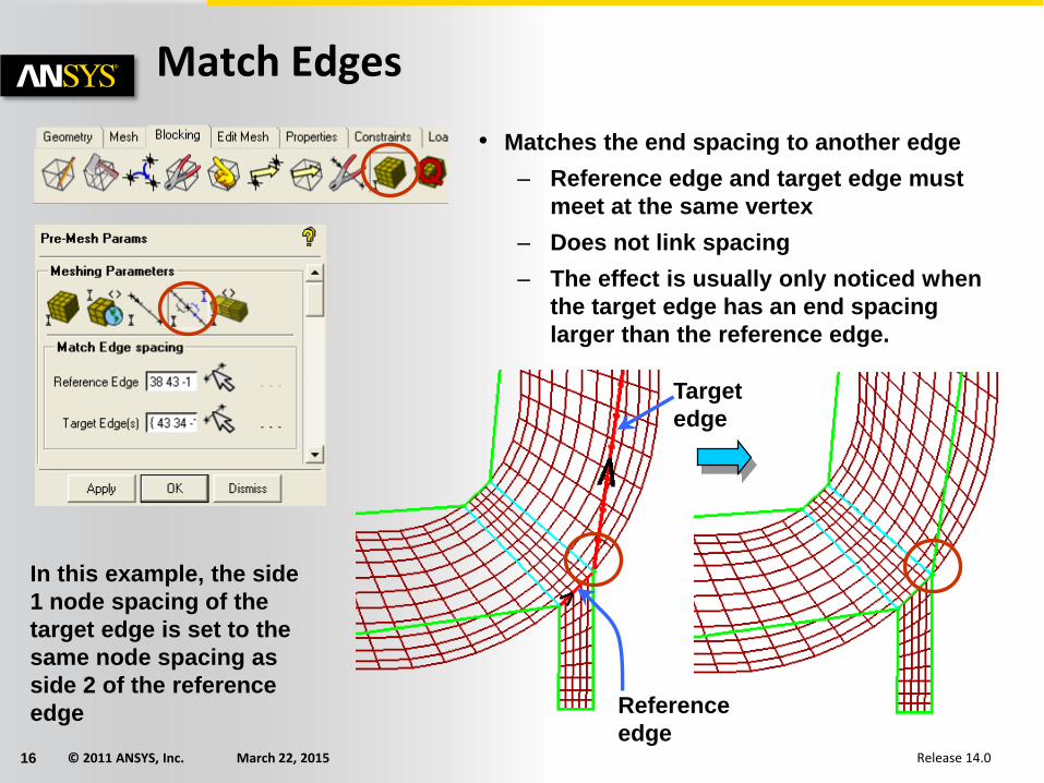
Match Edges
• Matches the end spacing to another edge
– Reference edge and target edge must
meet at the same vertex
– Does not link spacing
– The effect is usually only noticed when
the target edge has an end spacing
larger than the reference edge.
In this example, the side
1 node spacing of the
target edge is set to the
same node spacing as
side 2 of the reference
edge
Target
edge
Reference
edge
© 2011 ANSYS, Inc. March 22, 201517 Release 14.0
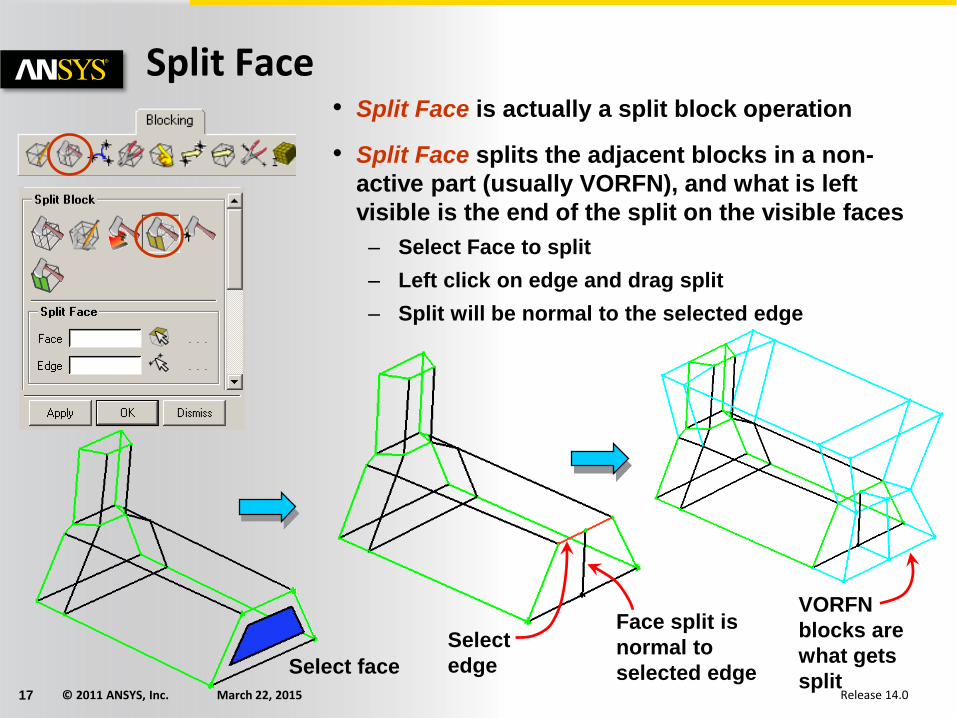
Split Face• Split Face is actually a split block operation
• Split Face splits the adjacent blocks in a non-
active part (usually VORFN), and what is left
visible is the end of the split on the visible faces
– Select Face to split
– Left click on edge and drag split
– Split will be normal to the selected edge
Select face
Select
edge
Face split is
normal to
selected edge
VORFN
blocks are
what gets
split
© 2011 ANSYS, Inc. March 22, 201518 Release 14.0
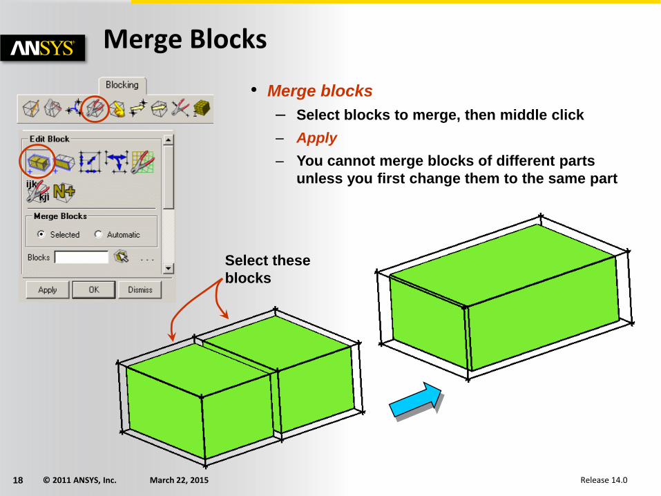
Merge Blocks
• Merge blocks
– Select blocks to merge, then middle click
– Apply
– You cannot merge blocks of different parts
unless you first change them to the same part
Select these
blocks
© 2011 ANSYS, Inc. March 22, 201519 Release 14.0
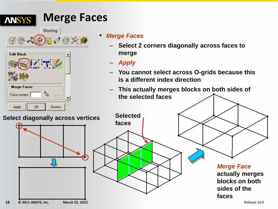
Merge Faces
• Merge Faces
– Select 2 corners diagonally across faces to
merge
– Apply
– You cannot select across O-grids because this
is a different index direction
– This actually merges blocks on both sides of
the selected faces
Select diagonally across vertices Selected
faces
Merge Face
actually merges
blocks on both
sides of the
faces
© 2011 ANSYS, Inc. March 22, 201520 Release 14.0
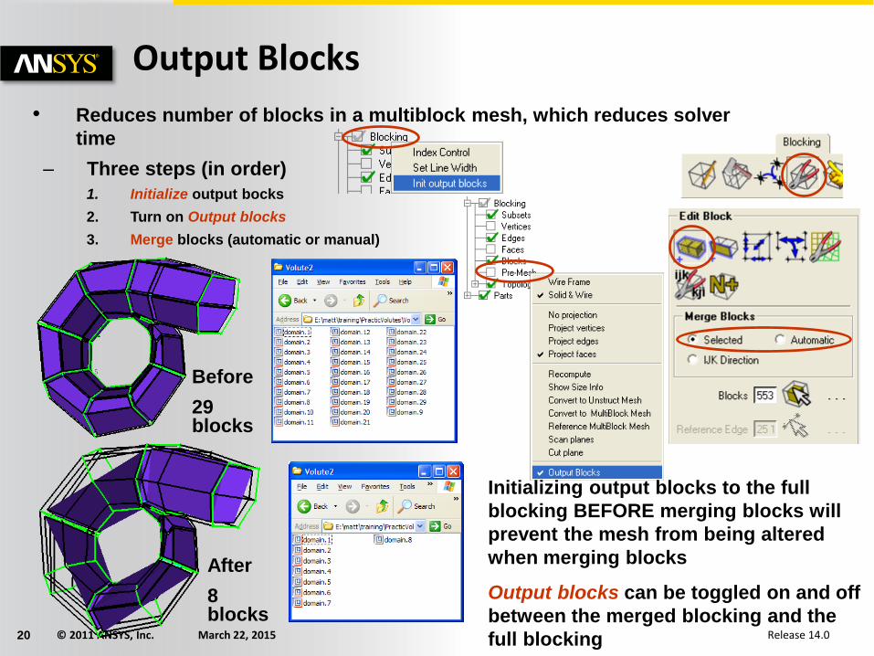
Output Blocks
• Reduces number of blocks in a multiblock mesh, which reduces solver
time
– Three steps (in order)
1. Initialize output bocks
2. Turn on Output blocks
3. Merge blocks (automatic or manual)
Before
29 blocks
After
8 blocks
Initializing output blocks to the full
blocking BEFORE merging blocks will
prevent the mesh from being altered
when merging blocks
Output blocks can be toggled on and off
between the merged blocking and the
full blocking
© 2011 ANSYS, Inc. March 22, 201521 Release 14.0
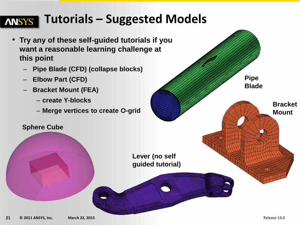
Tutorials – Suggested Models
• Try any of these self-guided tutorials if you
want a reasonable learning challenge at
this point
– Pipe Blade (CFD) (collapse blocks)
– Elbow Part (CFD)
– Bracket Mount (FEA)
– create Y-blocks
– Merge vertices to create O-grid
Sphere Cube
Pipe
Blade
Bracket
Mount
Lever (no self
guided tutorial)