Embed Size (px)
Citation preview

Cameras:
HD-IP
IC REALTIME SECURITY SOLUTIONS
ICIP D720-IRT12: 360 Degree Series IP Camera

Instruction
Manual
I C REALTI ME SECURIT Y SOL UTI ONS
ICIP D720-IRT12 IP Camera Instruction
Manual
IC Realtime 3050 N Andrews Ave Ext
Pompano Beach, FL33064 Phone 954.772.5327 • Fax 866.860.3860

Table of Contents 1. Features and Specifications.......................................................................1
a. Overview............................................................................................... 1
b. Features..........................................................................................1
c. Specifications..................................................................................3
d. Dimensions......................................................................................4
2. Camera Installation .....................................................................................6
a. General Overview ................................................................................. 6
b. Step by Step Guide .........................................................................7
c. SD Card Installation....................................................................... 8
3. Web Operation ............................................................................................9
a. Network Connection .............................................................................. 9
b. Logging In, and Main Interface.......................................................10
c. EPTZ Controls.............................................................................. 11
4. Appendices ................................................................................................13
a. Toxic or Hazardous Elements ..........................................................13

I C R E A L T I M E S E C U R I T Y S O L U T I O N S
1
Chapter
1 Features and Specifications
This section outlines the primary features of the ICRealtime ICIP D720-IRT12 IP Camera. It also outlines basic Architectural and Engineering specifications.
1.a Overview
his IC Realtime series product is an excellent situational awareness IP Camera
designed for the security field. It adopts an embedded Linux operating system to
maintain reliable, 24/7 operation. Utilizing both H.264 video compression and
G.711/AAC audio compression technology enables the highest quality of recorded
audio/video, while maintaining the lowest bitrate utilization.
The ICIP D720-IRT12 support 12 Megapixel with an integrated microphone. This IPC is fully
suited for full operation as a standalone device, or can be paired to one of our ICR Network
Video Recorders to add a great duration of recorded video.
The high recording resolution and extreme wide angle lens design makes this IPC well
equipped for installation in various institutions ranging from residential, commercial,
governmental, and enterprise environments.
1.b Features IC Realtime ICIP D720-IRT12 IP Cameras all support the following features:
• Real-time Monitoring
ICIP D720-IRT12 supports 4000*3000 @15FPS (P)/ 4000*3000 @15FPS (N) in Max FPS.
• Protection
T

I C R E A L T I M E S E C U R I T Y S O L U T I O N S
2
This product fully supports IK10 and IP66.
• Secure Archiving
Audio Video data is compressed and packaged into a secure and proprietary video format
(.dav files). This bolsters archived video integrity, and prevents vicious data manipulation.
Video is also watermarked with special data for evidentiary purposes.
• Compression Format
H.264 video and G.711/AAC audio enables high quality video recording while maintaining
the lowest file sizes possible.
• SD Card Storage
As a standalone device, the IPC can hold a 64GB micro SD card suitable for storing video
direct from the camera.
• Network Operation
Full system control (including live view, playback, backup, PTZ control, and system
configuration) is available with over the network. Client software is available for both Mac
and PC systems.
• EPTZ Control
This IPC includes a special de-warping algorithm, enabling users to „Virtually‟ Pan/Tilt/Zoom
across a high resolution image, in order to get the highest visibility and situational awareness
from the camera.
1.c Specifications
Model ICIP D720-IRT12 (PAL) ICIP D720-IRT12 (NTSC)
Camera
Image Sensor 1/2.3” 12 Megapixel CMOS
Effective Pixels 4000(H)x3000(V)
Scanning System Progressive
Electronic Shutter
Speed
Auto/Manual 1/3~1/30000 Auto/Manual 1/4~1/30000
Min. Illumination Color: 0. 1LUX/F1.2
S/N Ratio >52dB

I C R E A L T I M E S E C U R I T Y S O L U T I O N S
3
Camera Features
Day/Night Electromagnetic type IR-CUT, Support day/night mode
switch
Backlight
Compensation
BLC
White Balance Auto/ Manual
Gain Control Auto/Manual
Noise Reduction 3D
Privacy Masking Up to 4 areas
Lens
Focal Length 1.55mm
Max Aperture F2.2
Angle of View 185°/185°/185°
Mount Type Wall-mount, In-ceiling and bracket
Video
Compression H.264/H.264H/H.264B/MJPEG
Resolution 4000*3000 15FPS
2880*2880 20FPS
2880*2160 25FPS
2048*1536 25FPS
4000*3000 15FPS
2880*2880 20FPS
2880*2160 25FPS
2048*1536 30FPS
Frame
Rate
Main
Stream
4000*3000@15FPS
Sub Stream 704*576@25fps
Bit Rate H264:24k~12Mbps, MJPEG:64k~80Mbps
Network
Ethernet RJ-45 (10/100/1000 Base-T)
Protocol HTTP,TCP,ARP,RTSP,RTP,UDP,RTCP,SMTP,FTP,DHC
P,DNS,DDNS,PPPOE,IPv4/v6,SNMP,QoS,UpnP,NTP
ONVIF ONVIF Profile S
Max. User Access 10 users
Smart Phone iPhone, iPad, Android, Windows Phone
General
Power Supply DC12V, PoE(802.3af)

I C R E A L T I M E S E C U R I T Y S O L U T I O N S
4
Memory Slot Micro SD
Power Consumption <8W
Working
Environment
-40°C~+60°C, Humidity≤95%
Dimensions Φ150×47.7mm
Weight <1kg
Protection IK10, IP66
1.d Dimensions

I C R E A L T I M E S E C U R I T Y S O L U T I O N S
5
1.e External Cable
NO. Port Port Name Connector Function Description
1 AUDIO OUT
Audio output
port RCA Output audio signal to the speakers.
2 AUDIO IN
Audio input
port RCA Input audio signal, receive the analog audio signal from
the sound pick-up.
I C R E A L T I M E S E C U R I T Y S O L U T I O N S
6
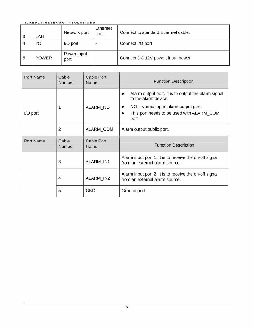
3 LAN Network port
Ethernet
port Connect to standard Ethernet cable.
4 I/O I/O port - Connect I/O port
5 POWER Power input
port - Connect DC 12V power, input power.
Port Name Cable
Number Cable Port Name Function Description
I/O port
1 ALARM_NO
Alarm output port. It is to output the alarm signal to the alarm device.
NO:Normal open alarm output port.
This port needs to be used with ALARM_COM port
2 ALARM_COM Alarm output public port.
Port Name Cable
Number Cable Port Name Function Description
3 ALARM_IN1
Alarm input port 1. It is to receive the on-off signal
from an external alarm source.
4 ALARM_IN2 Alarm input port 2. It is to receive the on-off signal
from an external alarm source.
5 GND Ground port

I C R E A L T I M E S E C U R I T Y S O L U T I O N S
7
Chapter
2 Camera Installation
This section outlines the proper way to mount and install an ICIP D720-IRT12 IP Camera. Suitable methods of installing the IPC include either Ceiling installation, Ground Installation, or Wall installations. Note that hardware including screws and anchors are included for the camera installation.
2.a General Overview
2.b Step by Step Guide
• Step 1: Remove the cameras dome cover
I C R E A L T I M E S E C U R I T Y S O L U T I O N S
8
Using the included hex wrench from the accessories kit, unfasten the 3 hex screws on the
dome camera enclosure and then remove it.
• Step 2: Place mounting template
Included with the camera is a mounting template that can be adhered to the target
installation surface for ease of installation. Following the diagram, bore 3 small holes as
indicated on the diagram, around the perimeter of the template. Once you‟ve created your
holes, insert the plastic anchors securely and firmly.
If you need to pass the cameras cable through the mounting plate, be sure to bore out the
template area marked „Cable Exit‟ to allow for the female RJ-45 plug to pass through.
If you need to pass the cameras cable through the side of the cameras enclosure, be sure to
snip out the Ushape knock out in order to allow the cable a wire path.
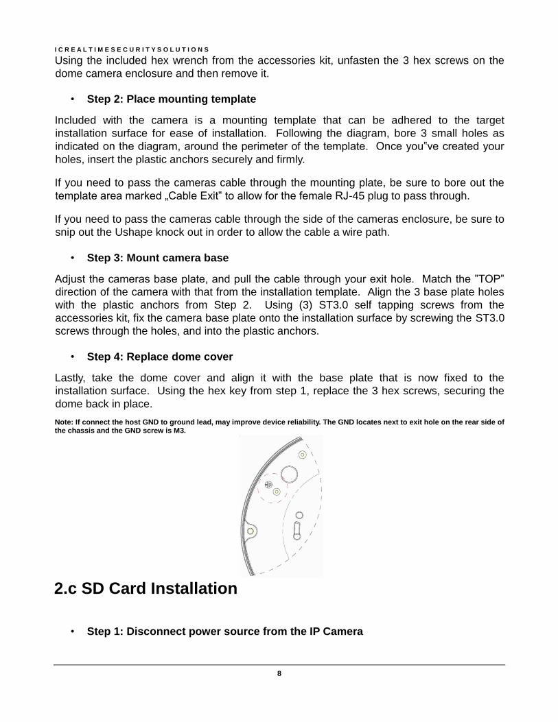
• Step 3: Mount camera base
Adjust the cameras base plate, and pull the cable through your exit hole. Match the ”TOP”
direction of the camera with that from the installation template. Align the 3 base plate holes
with the plastic anchors from Step 2. Using (3) ST3.0 self tapping screws from the
accessories kit, fix the camera base plate onto the installation surface by screwing the ST3.0
screws through the holes, and into the plastic anchors.
• Step 4: Replace dome cover
Lastly, take the dome cover and align it with the base plate that is now fixed to the
installation surface. Using the hex key from step 1, replace the 3 hex screws, securing the
dome back in place.
Note: If connect the host GND to ground lead, may improve device reliability. The GND locates next to exit hole on the rear side of the chassis and the GND screw is M3.
2.c SD Card Installation
• Step 1: Disconnect power source from the IP Camera

I C R E A L T I M E S E C U R I T Y S O L U T I O N S
9
SD cards shall not be installed or removed while the camera is powered and operational.
Doing so can potentially result in damage to the camera, and any data stored on the SD card.
• Step 2: Remove the cameras dome cover
Using the included hex wrench from the accessories kit, unfasten the 3 hex screws on the
dome camera enclosure and then remove it..
• Step 3: Insert SD card
Look on the base plate of the camera to see the section labeled “SD Card”. Insert your
micro SD card (Pin side down) until it clicks securely into place. At this point you can restore
power to the camera, and attach the dome cover again.
Chapter 3

I C R E A L T I M E S E C U R I T Y S O L U T I O N S
10
Web GUI Operation
This section outlines how to assign an IP address to the camera, and how to access and control the IPC via it’s built in Web Interface.
3.a Network Connection
• Step 1: Ensure the Camera is physically connected to your Network, and Powered
ON.
Patch the IP Camera into your network with a standard Ethernet cable. Provide the camera
with power either via PoE or with the separate 12VDC power input jack.
• Step 2: Assign an IP address to the IP Camera.
The ICIP D720-IRT12 Series camera (and all ICR IP Cameras) have a factory default static
IP address of 192.168.1.108. If this matches the same subnet as your LAN, you will be able
to login to the camera by typing this address into your browser (assuming that the IP
address does not conflict with another device on your network).
Alternatively, you can use our IP Auto Search utility to rapidly find and change IP addresses
for IC Realtime series IP Cameras. The utility is available on our support page at :
http://www.icrealtime.com/docs/IPAutoSearch.zip
3.b Logging In, and Main Interface
• Step 1: Open up your Web Browser (Safari, Chrome, Firefox, or IE) and input the
IP address of your IP camera.
In Example, open Safari and browse to http://192.168.1.108
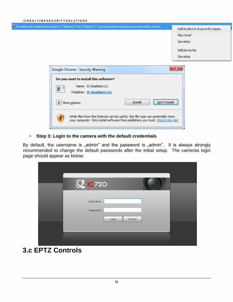
• Step 2: Follow the on screen prompts to install the plugin
When you first access the IP Camera over your web browser, you will be prompted to install
the plugin. See below:
I C R E A L T I M E S E C U R I T Y S O L U T I O N S
11
• Step 3: Login to the camera with the default credentials
By default, the username is „admin‟ and the password is „admin‟. It is always strongly
recommended to change the default passwords after the initial setup. The cameras login
page should appear as below:
3.c EPTZ Controls
I C R E A L T I M E S E C U R I T Y S O L U T I O N S
12
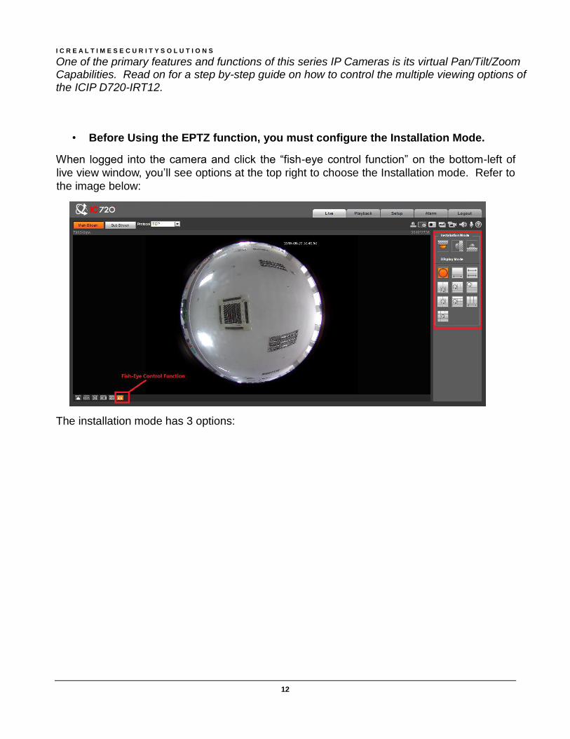
One of the primary features and functions of this series IP Cameras is its virtual Pan/Tilt/Zoom Capabilities. Read on for a step by-step guide on how to control the multiple viewing options of the ICIP D720-IRT12.
• Before Using the EPTZ function, you must configure the Installation Mode.
When logged into the camera and click the “fish-eye control function” on the bottom-left of
live view window, you’ll see options at the top right to choose the Installation mode. Refer to
the image below:
The installation mode has 3 options:
I C R E A L T I M E S E C U R I T Y S O L U T I O N S
13
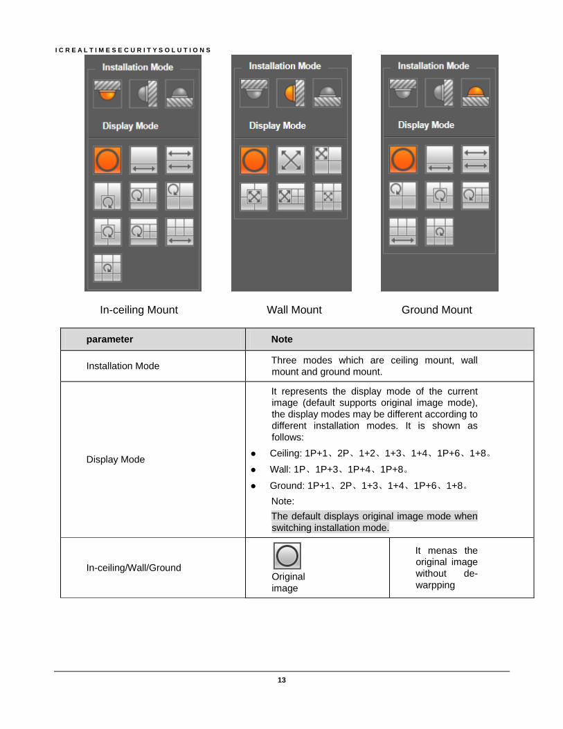
In-ceiling Mount Wall Mount Ground Mount
parameter Note
Installation Mode Three modes which are ceiling mount, wall
mount and ground mount.
Display Mode
It represents the display mode of the current image (default supports original image mode),
the display modes may be different according to
different installation modes. It is shown as
follows:
Ceiling: 1P+1、2P、1+2、1+3、1+4、1P+6、1+8。
Wall: 1P、1P+3、1P+4、1P+8。
Ground: 1P+1、2P、1+3、1+4、1P+6、1+8。
Note:
The default displays original image mode when
switching installation mode.
In-ceiling/Wall/Ground Original
image
It menas the original image
without de-
warpping

I C R E A L T I M E S E C U R I T Y S O L U T I O N S
14
parameter Note
In-ceiling/Ground
1P+1
360°expanded rectangular
panorama +
independent
sub image,
the sub image
and the
subbox in the
expanded
rectangular
panorama
support zoom
and
movement, for
the expanded
rectangular
panorama
also supports
left and right
starting point
movement.
2P
Two related
180°
expanded
rectangular
pictures, two
subwindows
form 360°
panorama
anytime,
which is also
called “dual
panorama”.
Two
expanded
rectangular
pictures both
support left
and right
movement
starting point,
which are also
linked by
eachother.

I C R E A L T I M E S E C U R I T Y S O L U T I O N S
15
parameter Note
1+2
Original image
+ 2
independent
sub images,
both the sub
image and the
subbox in the
original image
support zoom
and
movement.
The original
image also
supports
changing
starting point
by rotation (no
such display
mode for
ground installation).
1+3
Original image
+ 2
independent
sub images,
both the sub
image and the
subbox in the
original image support zoom
and
movement.
The original
image also
supports
changing
starting point
by rotation

I C R E A L T I M E S E C U R I T Y S O L U T I O N S
16
parameter Note
1+4
Original image
+ 4
independent
sub images,
both the sub
image and the
subbox in the
original image
support zoom
and
movement.
The original
image also
supports
changing
starting point
by rotation
1P+6
360°expanded
rectangular
panorama +6
independent
sub image,
both the sub
image and the
subbox in the
expanded
rectangular
panorama
support zoom and
movement, for
the expanded
rectangular
panorama
also supports
left and right
starting point
movement.

I C R E A L T I M E S E C U R I T Y S O L U T I O N S
17
parameter Note
1+8
Original image
+ 8
independent
sub images,
both the sub
image and the
subbox in the
original image
support zoom
and
movement.
The original
image also
supports
changing
starting point
by rotation
Wall 1P
From left to
right 180°
expanded
rectangular
panorama,
which
supports up
and down
movement
and changes
vertical angle
of view.

I C R E A L T I M E S E C U R I T Y S O L U T I O N S
18
parameter Note
1P+3
180°
expanded
rectangular
panorama+3
independent
sub images,
both the sub
images and
the sub box in
the expanded
rectangular
panorama
support zoom
and
movement,
expanded
rectangular
panorama
supports up
and down movement
and changes
vertical angle
of view.
1P+4
180°
expanded
rectangular
panorama+4
independent sub images,
both the sub
images and
the sub box in
the expanded
rectangular
panorama
support zoom
and
movement,
expanded
rectangular
panorama
supports up
and down
movement
and changes
vertical angle
of view.
I C R E A L T I M E S E C U R I T Y S O L U T I O N S
19
parameter Note
1P+8
180°
expanded
rectangular
panorama+8
independent
sub images,
both the sub
images and
the sub box in
the expanded
rectangular
panorama
support zoom
and
movement,
expanded
rectangular
panorama
supports up
and down movement
and changes
vertical angle
of view.
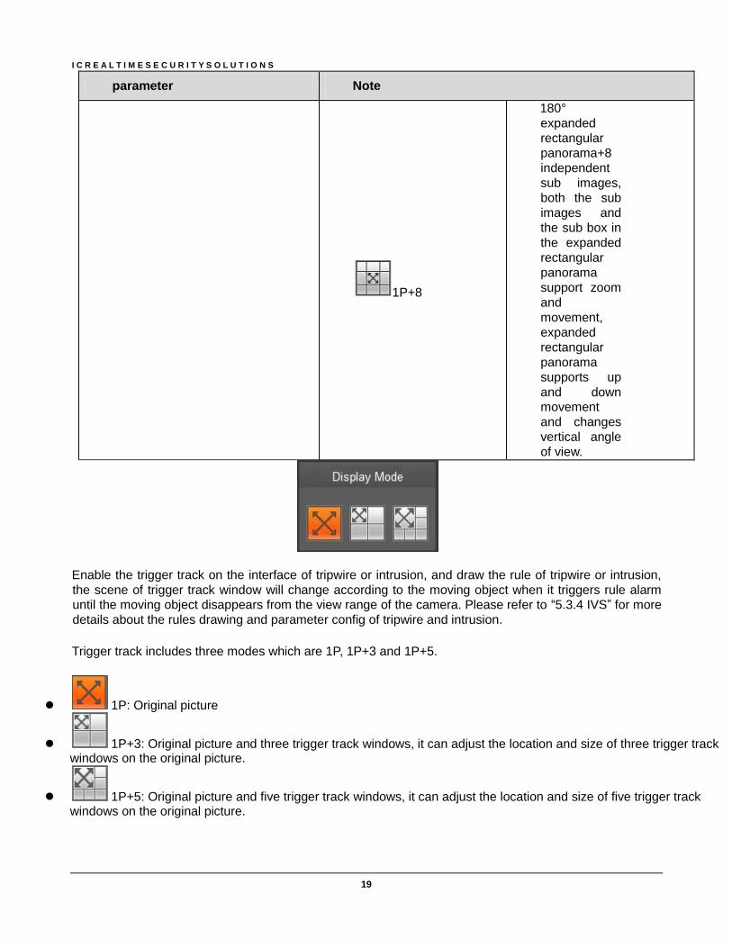
Enable the trigger track on the interface of tripwire or intrusion, and draw the rule of tripwire or intrusion,
the scene of trigger track window will change according to the moving object when it triggers rule alarm until the moving object disappears from the view range of the camera. Please refer to “5.3.4 IVS” for more
details about the rules drawing and parameter config of tripwire and intrusion.
Trigger track includes three modes which are 1P, 1P+3 and 1P+5.
1P: Original picture
1P+3: Original picture and three trigger track windows, it can adjust the location and size of three trigger track windows on the original picture.
1P+5: Original picture and five trigger track windows, it can adjust the location and size of five trigger track windows on the original picture.
I C R E A L T I M E S E C U R I T Y S O L U T I O N S
20
Chapter 4
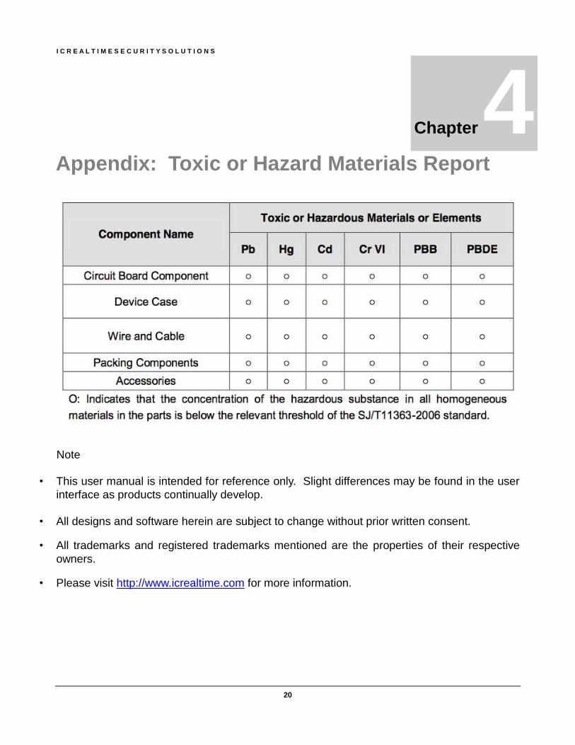
Appendix: Toxic or Hazard Materials Report
Note
• This user manual is intended for reference only. Slight differences may be found in the user
interface as products continually develop.
• All designs and software herein are subject to change without prior written consent.
• All trademarks and registered trademarks mentioned are the properties of their respective
owners.
• Please visit http://www.icrealtime.com for more information.