Embed Size (px)
Citation preview
Systems
GA26-1660-1 File No. 4300-07
IBM 3310 'D'irect Access Storage Reference Manual
--- ----- ------~ ~ ~ §~~

Preface
This publication is for use as a reference manual by data processing personnel. The purpose of the manual is to enable data processing personnel to become familiar with the characteristics of IBM 3310 Direct Access Storage. It is designed for the reader who already possesses a knowledge of data storage devices and concepts, but requires a source of reference material.
The publication lists the functional characteristics of the 3310, and describes the data format, storage capacity, and data transfer between the 3310 and the using system. The 3310 attaches to the IBM 4331 Processor via the· Direct Access Storage Device (DASD) A<i'Ipter. the Channel Commands section includes a list of all commands executed by the DASD Adapter to control the3310, while the Error Recovery Section includes information on error conditions and recovery.
The following publications are recommended for further reading; • IBM System/370 Principles of Operation, GA22·7000. • The functional characteristics manual applicable to the
parent system. Order numbers for functional characteristics manuals can be found in the IBM System/360 and System/370 Bibliography, GA22·6822.
• Fixed Block DASD Installation/Conversion Guide, GC2Q..1S79. . .
• IBM 4300 Processors Principles of Operation for ECPS: VSE Mode, GA22-7070.
• IBM 4331 Processor FunctionalChtiracteristics and Processor Complex Configurator, GA33·1526.
Second Edition, March 1979
T:.e 3310 Reference Manual is a major revision and replaces the Introduction to 3310 manual released in January, 1979.
Information in this publication is subject to change.
Requests for copies.of IBM publications shOUld be made to your IBM representative or to the IBM branch office serving your locality. # ..
A form for reader~s comments is provided at the back of this publication. If the form has been removed~ comments may be addressed to IBM Geheral Products Divrsion~ Technical Publishing. Dept. G26, 555 Bailey Ave., San Jose, CA 951S(}.
IBM may use or distribute any of the information you supply in any way it believes appropriate without incurring any obligation whatever. You may, of course, continue to use the information you supply.
© Copyright International Business Machines Corporation 1979
ii
Contents
C11apter 1. Introduction 1-1 General Description 1-1 Models of 3310 1-2 3310 Subsystem Configurations 1-2 Attachment of 3310 to the IBM 4331 Processor 1-2
Chapter 2. Data Organization 2-1 Sector Format 2-1
Id·entification Field 2-1 Data Field 2-3
Staggered Sector Addressing 2-3 Defective Sector Handling 2-4
Chapter 3. I/O Operations 3-1 Device Addresses 3-1 Data Addressing 3-1
Address Conversion 3-1 Logical Block Addressing in Data Sets 3-2
Access and Data Transfer Time 3-2 Data Integ,ritY3-2 _
Data Verification after Write Operations 3-4 Error Retry. 3-4 Error Logging (Logging Mode) 3-5
Chapter 4. IBM 4331 Processor Channel Commands 4-1 No Operation (Hex 03) 4·1 Define Extent (Hex 63) 4-2 Locate Command (Hex 43) 4-3
Locate Subcommands (Operations byte bits 4-7) 4-5
Read Command (Hex 42) 4-6 Read Initial Program Load (lPL) 4-6 Write'::iCommand (Hex 41) 4-7 Test I/O (Hex 00) 4-8 Sense I/O (Hex E4) 4-8 Sense Command (Hex 04) 4-9 Read,and Reset Buffered Log (Hex A4) 4-10 Read'-Device Characteristics 4-10 Diagnostic Control 4-11 -Diagnostic Sense ·4-14
Figures
Fig\lre 1-1. Figure 2-1. Figure 2-2. Figure 3-1. Figure 5-1. Figure 5-2. Figure 6-1. Figure 6-2.
_Figure 6-3._ Figure 6-4.
IBM 3310 Direct Access Storage iv Sector Format 2-2 Staggered Sector Concept 2-4 Example of Data Set Addressing 3-3 Error Condition Table 5-1 Recovery Action Table 5-2
. Sense Data Summary (Bytes 0 through 7) 6-1 Format Messages Summary (Sense Byte 7) 6-2 Sense DatQ,Summary (Bytes 8 through 23) 6-5 Sense Data (Bytes 8 through 23) - Format 0 6-6
Chapter 5. Error Recovery 5-1 Error Condition Table 5-1 Error Recovery Action 5-2
Chapter 6. Sense Data 6-1 Sense Information Summary 6-1
Sense Bytes 0 through 2 6-2 Sense Bytes 3 through 6 6-4 Sense Byte 7 6-4
Sense Formats 64 Logging Mode 6-4
Format 0 6-6 Format 1 (No Seek Check) 6-8 Format 1 (Seek Check) 6-9 Format 4 6-11 Format 5 6-12 Format 6 6-13
Chapter 7. Usage, Error, and Overrun Counters 1-1 Usage Counters 7-1 Error Counters 7-1 Service Overrun Counter 7-2
Chapter 8. Controls and Indicators 8-1 Model A Operator Panel 8-2
Power-On Sequence 8-2 Power-Off Sequence 8-2
Model B Operator Panel 8-2
Abbreviations A-I
Index X-I
Figure 6-5.
Figure 6-6.
Figure 6-7. Figure 6-8; Figure 6-9. Figure 8-1. Figure 8-2. Figure 8-3.
Sense Data (Bytes 8 through 23) - Format-} -: (No Seek Check) 6-8
Sense Data (Bytes 8 throt1gh 23) - Format 1 (Seek Check) 6-9 .~;'_.f."~"
Sense Data (Bytes 8 thro~gh 23) - For_m.at4 _ 6-1L Sense Data (Bytes 8 through 23) - Format 5 6-12 Seftse Data (Bytes 8 through 23) - Format 6' 6-13 3310 Direct Access Storage Unit Controls 8-1 3310 Model A Operatilr Panel 8-2 • 3310 Model B Operator Panel 8-2
ill

Maximum Subsystem Configuration
<Capacity 258, 080. 768 bytes)
Figure 1-1. IBM 3310 l)irect Access Storage {Design Model} , .
iv

Chapter 1. Introduction
General Description
The IBM 3310 Direct Access Storage is a magnetic disk storage subsystem, available in various storage configurations, that can be attached to the IBM 4331 Processor via the Direct Access Storage Device Adapter (DASDA). The 3310Direct Access Storage can be used for: • Data base/data communications. • Timesharing. • Systems residence. • General purpose storage. • Other applications requiring either random or sequential processing.
The 3310 Direct Access Storage provides: • A choice of four models. • On-line storage up to 258,080,768 bytes. • An instantaneous data transfer rate of 1,031,000 bytes per second. • An average access time of 27 milliseconds. • An average rotational delay of 9.6 milliseconds. • Rotational Position Sensing as a standard feature. • Error checking and correction of the data field content.
The IBM 3310 Direct Access Storage operates under control of the using system to which it is attached.
The 3310 can consist of from one to four disk storage devices housed in one or two .enclosures (two per enclosure). Each disk storage device contains a sealed unit that houses magnetic storage disks, read/write (R/W) heads, and an actuator that moves the heads. The disk unit is not removable by the user.
In addition, the first disk storage device in a 3310 configuration contains a controller that communicates with the adapter of the using ~yste{l1. The controller receives commands from the system in the form of bus and tag sequences, decodes them, and decides whether a particular command is for itself or if it must be passed to one o(the~ssocia~eddi~storage devices. '.·'/i'.' ;;,1"0'" .' ."'~ .
,~,.,;:~.Jbe,elevellread/\\'rite heads can be moved t~ 360 access poltions (cylinders). ' 5~cYlitiderl!64ls teseryed"asall aItemate cylinder;, cylinder 359 is used as a CE cylinder. s;,;,Ea~;'~aCk.~is'diVid~ into 33seciors;,secto~:Qthro.ugh 32.' Sectors 0 through 31 i'canre:'ii~<iresseci by"thesystelIl· Sector 32 isispare.Any given sector is uniquely '~ancf completely identified by' an 'identifier (10) field'\vhich contains a flag byte, the cylinder address, head address, and sector number bytes. Inadqition to the identifier field, the sector contains a data field of 512 data bytes. The basic uilit of transfer between the disk storage device and the using system is a fixed block of data of 512 bytes, that is. the data field contained on one sector.
The main characteristics of the device are:
Total No. of primary blocks per disk storage device Total No. of alternate blocks per disk storage device Total No. of blocks in CE area pe! disk storage device No. of user.acc~ss positions ( cylinders) No. of blocks per access position No. of moving heads No. of blocks per track Device capacity
1-26016 352 352 ~S8
352 II 32
64,520,192 bytes
Olapter 1. In trod U.C tion 1-1

Models of 3310
3310 Subsystem Configurations
Attachment of 3310 to the IBM 4331 Processor
Four models of the 3310 are available: • Model Al - contains a controller and one disk storage device in an enclosure. • Model A2 - contains a controller and two disk storage devices in an enclosure. • Model B 1 - contains one disk storage device in a separate enclosure. The model
B 1 must be physically attached to a model A2 from which it derives its power and control functiQns.
• Model B2 - contains two disk storage devices in a separate enclosure. The model B2 must be physically attached to a model A2 from which it derives its power and control functions.
The drive mounted in the bottom of the Model A2 enclosure always contains the first address in the string.
The 3310 models, AI, A2, Bl and B2 can be arranged in any of the following subsystem configurations:
, Configuration
'3
4
Descrip tion
Model Al First enclosure ~ Storage capacity ..... 64,520,192 bytes
Model A2 First enclosure Storage capacity - 129,040,384 byt~s
Model A2 and Model B 1 , First and second enclosures Storage' capacity'''':' 193,560,576 bytes
Model A2 and B2 First and second enclosures E'~orage -capacityi~~.258,080,768, . bytes
A complete four-drive configuration is' shown in Figure 1.
The.3310 direct access storage attaches to the IBM 4331 Processor through the Direct' Access Storage Device Adapter (DASDA) of the 4331 Processor. Movements of the read/write heads to particular tracks on the ma'gnetic disk of the disk storage devices and the reading or writing of data, are controlled by command signals from the system via the DASDA to the 3310 direct access storage.
Commands issued by the 4331 Processor are executed by the adapter and transferred to the 3310 in the form of bus and tag sequences to initiate the required action.
1-2 IBM 3310 Direct Access Storage Reference Manual

Chapter 2. Data Organization
Sector Format
Identification Field
Flag Byte
TItis chapter describes the data organization of each disk storage device in the 3310 Direct Access Storage subsystem. The basic unit of data transfer between the 3310 disk storage devices and the using system is the 512 byte block of data from one addressed sector. This chapter concentrates on the format of the sector.
Each track is divided into 33 sectors (0-32) of 600 bytes. Sector 32 is reserved for use during manufacture as an alternate sector. Cylinder 64 is reserved for alternate
sector usage. Cylinder 359 is reserved for diagnostic purposes. This means that there are 126,016 sectors available to the using system as primary blocks.
;'; ... ~~>::, .. :.':.'; .'t.~:···>~.:(!,;: . ·;>,'!4"~:'~:. y,;,,,,,' .:.>'/::', . '.: .. ":':', t; ::.:'~.<'::-~;~<' ' ': .. ': ;.,..' ~i~/~ :.~ y r·,~.: ';:};\' :~~~: ;,:";~. , .. -<.~, ',:' ~ . ··,,;t:~ ',:,;' .Eacll s~t()r ~asa .. gross length-:ol 6OO,bytes:and is made up:~f,tw~ basic· areas::'": ' Y~,?~j;p?rdentifiCation (ID) field:~h.!c~:eo~t~s_ th~'~gbyte~ 'Sector:~liead;'arid;~~-i1.:r:<, ... ~;,~iri1r;~;eyunder'numbers plus'cyc1ic'che~k'byie; ~~:::"'-' .' ;~. ,~;;,,:;-~.,,:, '., .:.:;I··.~·:';~'v,:':::,,'-;">L"· .... ·~;: .• J'~:t>aia:t~eld~bich contains the 512 byte data field pl~~'-t~~\~n:~r't~~iT~~tio~ 'cOde ".,!;~;'~i.~~f;~i;:;f(;'·'/~~:!.:il::f:t::~(:r "\\',~;;Ai,"""" "',,:<;j~\~(:: ' .
The sector identification (ID) field contains the physical address-of the sector, and consists of a flag byte followed by three address bytes, and two cyclic redundancy check (CRC) bytes.
The flag byte indicates to the using system the condition of the sector. Bits in the flag byte have the following significance.
f:'" Bit " O' Derectlve" Field 2' <':!"~:i:tJr ~}~'Bit 1 Defective' Field l"';';iifO}e%} f"Bit2Write·~~t~t ... ~·",.:~i1~";;,,,j~:~
:-~!, '.~_. Bit" 3 Write Prot~t 1 ~~l:~·< -~>,,,,,,«:..;g;1
lit:!~. ::~ta;t~:;"t~~~~ ,i." Bit 6 Sector. Defective';:'('~~'i;';1::t')~'~~1' ::lj,:1:Bit '7 Alternate Sector::'~'-r;;"" :0) . .... . <·On'the 3310 disk storage devices, the descriptor flag byte bits have'the following'
.' ~earurtg:ii",!.}t;/",:/:;f£;:.:.· -'~".' 'C~",,: i h-;''',;. . . '~"'~':,~';-: . ';':'.~":t:;::U;!ifb:>,>~·:,: ;i.';·~ ~'.~ - .~." •
"··~~:~;~~~~!rt;~¥;I'i" L):()()() l>'~'" Available alternat~s~c;~~7 :~~~. ..' {(,-00 10 . ·~:':.Pefective, Iogi~arsectornu~b~t32.:.':~%) ':..~~(.r "',' " .. ?I :.,,\: ,."' ". ·':·'~··"·.·:i .. /:.~.. "\'; -,":: '"..-L";.,~.~: ~:"'.,"""i_.,:_". ',: ..... "",~·~·'·~/:;i':c·::::.:.'~.,f
J:i: 0011 = ·Defective altemate·sector······~, ·',·-:.,:;;~);~;i.;,'~1~'1' .;j.;~1:"···01·00 =:':i·,not·u·· 'sed .:,', .,. /.·.~x;·~;~~;rilhl~~··~W~~~~t;~t1!h~h~~;;~.t~~f.N!;jzr;\,·y.,..::·"}'::,~~' .:.~·:.~:~;~~.;-'.,,~,~·,·.'.!.:,·.·~,':1... .. :~{t.:,';.·.:.{<;.,.:,;.~~.~,:~.;~.~~?~.~:.f; .. -.,,~:,;t.;_/.~~.,"X .. '.I:ir.~~.t~.,~/;>.~.;.~'l:".( .. '-, .. >.~,~ .. b.~ ;1 ::- '~'::. . .' '.: .)-:- . .,' ,'.:- , ," .",: .~~" .. : . .;.;:\~r~:~.;.;"<?';:;·"::>i>.';~,:.,.,' . .;;~';.'~~~~~t ... ;~:: ":)~ l,:~.,·;'.~·~.~ ''':' <," '" " "" , .. :"..:~r, "": ,:,;::'" j:. : _ ...-: : ' .: ~':; , " , '. '?"
~~~:}~:OlOk;"~tAlternate:assignedsector;::.prunarysector not displaced:(llcjt~),;.9;;';;~~
!',~/.~!!~.:·!:'=,~~:1ve.sector not .. in. displac,e~=·':~~:7;:.·;;ir.;:~i:;:;t , 1000 == Good primary sector, displaced. ' , ',,< ':'~0X;' ,'- . '?{
>,I • " d .... .. ...~.... .1:<- • ! I '"' ~ <J!J,l ".. ~ ., ~"'r'" ~~ , ~;.~::l!I " .,,:, '::.;: -lOt)} = nOluse .• . ... ;..... ,.." ...... , •......•. '., ". !,' .
';'1010=:= 'Defective sector, factorydlsplaced (sector ren:uinben!d32) 1011 =not~used' ":}'::''',/':. .. <.' '';; . . ....
1100 = 'not used 1101. == Alternate assigned sector, primary sector displaced 11I0 = Secondary defective area in displaced area 1111 = not used
Chapter 2. Data Organization 2-1

o
Sector Start
14 Bytes of 00
14
I
1 Byte (Sync Byte)
CRC Check Bytes
16 bytes of 00
Address Bytes
1 byte (Sync Byte)
.----.....,512 Data Bytes
512 Bytes
BYTE 0 BYTE 1
0 1 2 3 4 5 6 7 0 1 2 3 4 5
4 Bytes ECC
00
24 Bytes
Sample Servo Area
BYTE 2
I 6 7 0 1 2 3 4 5 6 7
x 32 16 8 4 2 1 x x 16 8 4 2 x256 12864 32 16 8 4 2 ~ ~--- 'v' ---Sector Address Track (Head) Address Cylinder Address
F1agpyte
Bit Significance
0 Defective Field 2 1 Defective Field 1 2 ~r-ite Protect Field 2 3 Write Protect Field 1 4 Sector Displaced 5 Sector Reassigned 6 Sector Defective 7 Alternate Sector
Figure 2-1. Sector Format
2-2 18:"1 3310 Direct Access Storage Reference Manual

Address Bytes
CRC Bytes
Data Field
ECC Bytes
Staggered Sector Addressing
Note: The combination alternate. reassigned, and the first field write protected is an indication of a factory-flagged sector. This sector should not be overwritten.
The flag byte can be read using Diagnostic commands.
The three address bytes are located immediately after the flag byte and contain sector address information. This information is defined in terms of sector number, head number, and cylinder number. The relationship between the address bytes and the r.elative block numbering used by the system is described in Chapter 3, I/O Operations. The sector address as written on the disk can be read by the system by using the Diagnostic Control command. Refer to the description of the command in Chapter 4.
The two CRC bytes are used for error detection, and are located immediately after the address bytes.
Within each sector,the data field contains a block of 512 bytes. Each field is followed by 4 bytes of error correction code (ECC). The data for this fie~d is transferred to or from the system under control of the byte count in the CCW. ~f, on· a write data operation, the byte count becomes less than 512 bytes, the data.:tfield is padded to the end of the field with zeros.
Validity checking of the recorded data is accomplished by adding four bytes of information to each data block. These four bytes allow error d~tection and provide the basis for error correction. .
They contain the syn~me bits (check bits) which allow correction of single·error bursts with a maximum length of three bits. Such error areas may be found anywhere within the tota1516 byte record (including the error correction"code itself). A single burst of errors of up to 14 bits in length is detectable.
When the 3310 is transferring data to or from the IBM 433f!Processor via the Direct Access Storage Device Adapter (DASDA), correctable errors a~e automatically corrected. The appropriate error counter is stepped to indicate.:that an error had occurred. In error logging mode, correctable errors aJ:'e flaggedtto the system through sense bytes. ",
Large volumes of data are sometimes required to be read or written on sequential sectors and tracks. In these cases,after all the sectors remaining on the first track have been written the next sequential head is selected and .writing continues on the next track. It requires a maximum of eight sector periods for t~e read/write heads to stabilize after a head change; therefore, to ensure that data transfer can continue with the minimum interruption, sector numbers on each succeeding~rack are shifted by eight sectors (see Figure 2,.2). This avoids the· requirement to VIllit for a full disk rotation before restarting the read or write operation.
Note: Sector 32 is not included in the staggered addressing. Sector 32 is always the 'Sector- immediatCIy before the index puls~, unless it has-been displaced (see Defective Sector Handling).
Chapter: 2. Data Organization 2-

Index Pulse
1° I
I I 110,. I I I I
Figure 2-2. Stagge!ed Sector Concept
Defective Sector Handling
< :I Rotation
11°1 120) 13~ t21 Head 0.4. B
Head 1.5,9
130, 1° I I , COl Head2,6,10
Head 3,7
When the storage disks are manufacturedta detailed surface anaIysisis made. The location of small surface defects (which could cause a loss of data) are noted and avoided when the
. disk is formatted by using alternate storage sectors. While each track contains 33 sectors, only 32 are used. The-extra sector is used as an
alternate if a def~ctiVe sector is found on the track. If more than one . defect is found on a track, ad<ditional alternate storage sectors' are placed on cylinder 64, reserved for this purpose.
The above operation is performed automa;ically by the 33 I o and the DASDA. and is transparent to the user.
Should a new defect be found with the me in use (indicated by.permanent error, data check, and check data error), the user must flag the defective sector and reassign it
. to an alternate. Utility programs for this purpose ate de'scrlbed in DOSjVSUtilities, Order No. GC33~5381-3.
The Locate command with the Format Defective Block subcommand is used to assign an alternate block as follows:
1. Seek to cylinder 64 using the head that detected the defective sector ~ and search fot . the first available sector on track 64. 2. Save the alternate sector address and seek to the defective sector. 3. Rewrite the ID field of the defective sector (moved by 64 bytes if necessary) with
the flag byte sho·wing the sector defective and reassigned~ and ad4ress bytes that .coatain the address of the alternate sectGf.
4. Seek to the alternate sector, write the ID field with the flag byte showing alternate assigned sector, and write the address bytes pointing b,pck to the defective sector. Note that the above is purely a relocation of sector address, no data field is written.
2-4 IBM 3310 Direct Access Storage Reference Manual

Chapter~. I/O Operations
Device Addresses
Data Addressing
Address CODYersion
This chapter describes the Input/Output operations used with the 3310. Additional information about the processing unit and channel program control of I/O Operations is found in the IBM 4300 Processors Principles of Operation for ECPS; VSE Mode, GA22· 7070.
Up to four IBM 3310 Direct Access Storage subsystems can be attached to the Direct Access Storage Device Adapter (DASDA) of the IBM 4331 Processor. Each 3310 string can contain up to four disk storage devices.
The eight bits in the unit address byte derived from the Start· I/O instruction identify the 3310 subsystem and the individual disk storage device as follows:
Bit Number
o 1 2
'3' 4 S 6 7
Assignment (Hex)
Not used Not used
3310 subsystem address
Disk Storage Device Address*
• Note: lithe 3310 string has only 2 devices, bit 6 is not used (set to zero).
&ch disk storage device in the 3310 subsystem appears to, the U5ing system as consistiIlg of 126,016 512-byte blocks consecutively numberedftom 0 to 126,015. The blocks are addressed in terms of the displacement, in blocks~ fr~~ the start of the device (that is, from block 0). The displacement is called the Physical Block Number (PBN).
In the DASDA to which the 3310 controller and disk storage divices are att~thed, i
the block displacement is translated into cylinder, head, and sector numb~rs which are then compared to the address bytes on the disk to locate the correct sector before data transfer begins.
Chapter 3. I/G Operations. 3-1'

LogicaJ Block Addressing in Data Sets
Access and Data Transfer Time
Data Integrity
The logical blocks of a data set are recorded on the di:sk storage device in one or more data extents, each of which consists of a number of consecutively numbered physical blocks starting with a specified block. All channel commands chained to the Define Extent command must operate within the limits defined by the data extent.
Figure 3-1 shows an example of a data set consisting of two extents~ the second of which is defined here. Note that the block number given in bytes 4-7 of the parameters of the Define Extent command (location of the first block of the extent) is relative· to the start of the device~ but the block numbers in bytes 8-11 and 12-15 (first and last block~ of the extent) are relative to the start of the data set.
Details of these and other channel commands are given in Chapter 4.
The total time required for access and data transfer is a combination of the following:
Access Time is measured from the receipt of an access command, up to (and including) the settling of the heads at a cylinder location.
Head Switching Time is the time needed to switch ~rom on~ read/write head to the next sequential one.
Rotational Delay is the time required for a data record to reach the required read/write head. The magnetic storage disks rotate at 3125 revolutions per minute (nominal). The time required for a specific record to reach the heads is a maximum of 19.1 milliseconds. Half a revolution, 9.6 milliseconds (the average delay) is generally used for ti~ing purposes;
All 3310 disk storage devices use rotational position sensing. This permits the :-disk storage device to disconnect from the channel during the time required to
bring the correct record to the read/write head. Other disk storage devices can be used by the adapter during this period. .
• Zero Track Access time:
Head switching time 4.8 milliseconds
• Access times:
One cylinder 9 milliseconds
Average 27 milliseconds
Maximum 46 milliseconds
• Rotational delay:
Minimum o milliseconds
Average 9.6 milliseconds
Maximum 19.1 milliseconds
The 3310 and its associated controller provide data integrity by error detection and correction.
When attached to the IBM 4331 Processor, the 3310 and the DASDA(Direct Access Storage Device Adapter) provide data integrity in the following ways: • Validity checking of ID and data fields. • Automatic error retry. • Error logging.
3-2 lBi\f 3310 Direct Access Storage Reference Manual

EXTENT 1 EXTENT 2 (DEFINED HERE)
DEVICE CIJj! ~~_ it ,~_~~ ~to PBN 0 1 / I " 147 148149 156 245 246
I ,',' TO BE READ / ~ 126,015
I I /' " I I ~ /
I I ' , I 1 ,," /"
1/ ,
DA:::ET ~: '48'49(0 51 52 ~tJ;C~' PBN: PHYSICAL BLOCK NUMBER lBN: LOGICAilf BLOCK NUMBER
CHANNEL PROGRAM Bit
J..--- - ----- -CHANNEL COMMAND WORD- - - --- - --I o 7 8 31 32 3738 40 47 48. 63
CODE DATA ADDRESS FLAGS 000 NOT USED COUNT
DEFINE EXTENT X' 63' X' 002000' 01000~ 000 0····0 16
LOCATE X'43' X' 002428' 01000 000 0-··0 8
READ X'42' X' 003000' 00000 000 0·· - 0 4096
t· CC (Chain Command) ,
~XTENTPARAMETERm BLOCK SIZE PBN OF FIRST
DATA ADDRESf MASK UNUSED (BVTE~) BLOCK IN EXTENT
X' 002000' L.. __ X_'O_O_' --I_x_'0_0'_LI __ 5_1_2_* --11 ......... ___ 1_4_7 __ ---'
BYTE 0 2 3 4 7
LBN Of FIRST BLOCK DATA SET
LBN O~LAST BLOCK DATA SET
(LOCATE PARAMETERS) OPERATION
DATA ADDRESS X' 00 24 28' X'06'
BYTE 0 .
(READ BUFFER)
OATA ADDRESS
X' 00 30 00' I' I BYTE 0
50
8
AUXILIARY INFO . BLOCK COUNT
X' 00' 8
2 3 4
149
11 12
LBN OF FI RST OF SUCCESSIVE BLOC~S
50
· ~ ~J.---_-.' ----' 4095
• If this field is specified to be all.zero, the default block size is 512 bytes.
Figure 3-1 Example of Data Set Addressing
15 I
Chapter 3. I/O Operations 3-3

Data Verification after lVrite Op'eratfons
Error Retry
Seek Error Retry
Data Check Retry
Validity cl).eckiI1gQ{the recorded data is accomplished by adding 4 bytes of inf ormation to each data area of a 512-byte record. These four bytes allow for error detection and provide the basis for the error correction capability.
Validity checking of the ID field occurs in the 3310 controller using the CRe bytes attached to the ID field (in both read and write operations).
Data can also be verified explicitly by employing the Write Data with Verify specification in the Locate command. In this case the DASDA will reorient to the beginning of the blocks just written. The data will then be read whereby the ECC code is again generated as during writing. Thereafter the written ECC is compared with the generated ECC and if both are equal t the data has been successfully verified. If an error is detected the read operation is retried 8 times. If thereafter the compare result of the ECC bytes is still unequal, the write operation will' be retried 4 times and if the error persists, unit check, permanent error, and check data error will be presen ted. '
Error retry is initiated automatically without requiring an I/O interrupt to recover from: • Seek Malfunctions. • Data Checks. • Data Overruns.
If the reiritums out to be successful, the current command (Locate, Read, or Write) will be completely executed before retry mode is reset. The corresponding error counter is stepped by one.
Seek errors are detected by an ID mismatch from the disk storage device, or if track unavailable or no home is indicated after execution of a Recalibrate.
The 3310 will perform a recalibration and reseek to the desired cylinder (head) if a physical address mis~atch is detected du~g ~eek verification.,
, -Seek verification m-..y be ~xecuted after: 'f
1. An access executeq due to a Locate command. 2. An implicit seek (cylinder advance), or 3. A head switch.
Implicit seeks or head switches are performed if track or cylinder boundaries have to be crossed during ~ad or Write operations.
Seek verification is accomplished by comparing the track address (CCH),read from the disk storage device with the cylinder and head address bytes derived from the command that initiated the seek for that device. Any mismatch indicates that the access mechanism is not properly positioned. Seek Error Retry is invoked to cause repositioning of the access over the correct track.
The erroneous operation will be retried up to ten times. If the disk storage device is in Seek Error Logging Mode, Format 1 Sense Bytes are generated when the error appears the first time (with Sense Byte 2, Bit 3 active). After ten unsuccessful retries Format 1 Sense Bytes are generated with Unit Check set in the Unit Status Byte.
Data checks are detected by CRC check or ECC check from the disk storage device. The DASDA automatically attempts recovery by two methods, either by error correction via the error correction code or by retry. Th~ details depend on the operation, as follows:
3-4 IBM 3310 Direct Access Storage Reference Manual

Data Overrun Retry
Error Logging (Logging Mode)
Read Operation: When a data checkis detected during aread operation, the DASDA checks whether the data check is correctable. If so, correction occurs using the correction code pattern against the affected data field. If the data check is not correctable, the read operation is retried eight time's, If the 8th retry is also unsuccessful, permanent error and check data error are indicated.
Write Operation: During a write operation the recovery action depends on whether or not verification has been specified. If write without verify has been specified, the DASDA does not detect any data checks and simply continues with the next command. If verify has been specified, the data blocks are read back after writing, whereby the ECC is generated once more just as occurred during the preceding write operation, and therefore the written ECC and the ECC which is generated during the read back operation should be identical. If the ECCs do not match, the read verify operation is repeated up to 8 times. If the error still exists, the write operation is retried up to four times. If the 4th attempt is also unsuccessful, permanent error and check data error are indicated.
When Data Overrun has been indicated during data transfer (outbound: DASDA buffer empty, inbound: DASDA buffer full) the DASDA will repeat the reading or writing of the interrupted ID or block of data. ,',"
If the Data Overrun persists after 32 retries, Format 0 sense bytes are generated with Unit Check set in the Unit Status Byte.
In the IBM 43.31 Processor, each disk storage device is allocated a specific control block (Drive Information Block) which includes usage and error counters. These counters are described in Chapter 7.
When an error counter overflows before the corresponding us~ge counter, it may mean that too many errors are occurring on a disk storage device, even though the errors are being corrected automatically on retry. The disk storage device is therefore set into Error Logging Mode. (The usage and error counters are also offloaded and reinitia~ed, see Chapter 7). ~
Whenever a disk storage device in Logging Mode encounters a successfully retried error of the same type that caused it to enter Logging Mode, 24iense bytes of environmental data (Sense Byte 2, Bit 3 active) are collected by the microcode.
The next SIO addressing this disk storage device is not executed. Instead, initial status indicates Unit Check. The operating system will then issue a Sense command to fetch the environmental data and will reissue the SIO. The sense command will retrieve sense data in the appropriate format depending on the error causing the logout:
• Format 1, if the error is a seek error. • ' Format 4, if the error is a data check retried. • Format 5, if the error is a correctable data check (sense byte 2, bit 7 will also be
on in this case). k
Logging Mode terminates if: 1. The disk storage device logged error data four times, or 2. A second disk storage device enters L~gging Mode before the first has finished.
When this happens, Logging Mode is reset Jor the first disk storage device. Only one disk storage device at a time may be in Logging Mode. ".
Chapter 3. I/O Operations 3-5

Chapter 4. IBM 4331 Processor ChanneI'Commands ", ".- .-~ -~:. '.~- ~>- --
The following channel commands are executed by the DASD Adapter of the IBM 4331 Processor and result in actions at the 3310 Direct Access Storage:
Command Type
Control
Read
Write
Test'
Sense.
Diagnostic
*
Command Name
No-operation Define Extent Locate
Read ReadIPL
Write
Test I/O
Sense I/O Sense
~
Read and Reset Bl;lffered Log Read Device Characteristics
Diagnostic Control Diagnostic Sense
Note: Any other command bit configurations are considered invalid
* Test I/O is an I/o' instruction~ not a channef command.'
Hex Code
03 63 43
42 . 02
41
00
E4 04 A4 64
F3 C4
No Operation (Hex 03)
Byte 0 1 I 2 , 3 4 5 6 1 7
Command Data Address Flags 000 Not Used Count Code
Binary Not checked for validity; should not exceed SU flag (bit 2) Must be non-zero; zero count 0000 0011 addressing capaci,ty. should be on causes a program check. Hex 03
• Chaining and Special Requirements: None . . No-op command causes no action 10 be taken by the address~d device.
Status: Channel end and device end are presented during initial selection_
..
Chapter 4. IBM 4331 Processor Channel CommaI'lds 4-1

Define Extent (Hex 63)
Bvte 0 1 I 2 I 3 4 5 6 f 7
Command Data Address Flags 000 Not Used Count Code
Binary Specifies storage location of the first byte of the Used at the Sixteen 01100011 parameters. Hex 63
Chaining and Special Requirements:
discretion of the program-mer.
If not the first Define Extent command in the chain, it must be permitted by previous Define Extent (see mask bits).
Sixteen: bytes of data are transferred from the system to the DASDAdapter. These 16 bytes represent parameters which define the size and location of the data extent and, thereby, the bounds within which subsequent chained commands may operate. The inhibit mask is included in the 16 bytes and either allows or prohibits an operation (see Mask Byte ).
Parameter Definition
Byte 0: Bytes 1-3: Bytes 4-7:
Bytes 8-11:
Bytes 12-15:
Mask Byte. Must be zero. Define the offset, in blocks, from the beginning of the device to the
. first block of the extent. Defme the relative displacement, in blocks~ from ·the beginning of the data set to the first block of the extent. Define the relative displacement, in blocks, from the beginning of the data set to the lastblock of the extent.
Note: The entire extent defined by bytes 4·15 must lie within the limits of the addressed device, otherwise the-IJefine Extent command is rejected.
4~2 IBM 3310 Direct Access Storage Reference Manual

Byte 0 (Mask Byte) allows control over the following operations through the mask bits as defined below:
Bits 0 and 1 00 = Inhibit format write operations .01 = Inhibit all write operations 10 = Unassigned (must not be set) 11 = Allow all write operations
Bits 2 and 3: Unassigned, must be zero.
Bit 4 (Defines the area in which the extent resides.) . 0 = The extent resides in the data area
1- = The extent resides in the CE-area (see Note).
Bit 5 (Controls diagnostic commands.) ~=; . Inhibit diagnostic commands 1 = . Allow diagnostic ·commands
Bit 6 (Controls additional define extent commands.) 0= Inhibit additional define extent commands 1 = Allow additional define extent commands
Bit 7: Unassigned (must be zero) ..
Note: The CE area is .8 separate linear addressable space of 512~byte blocks. This area may be accessed by making bit·4 active. The contents of bytes 4-15 will then be ignored. The. parameters will be sct impljcitly so that the data set is identical to one extent that cove.rs the whole CE area (parameters 0, 0, 351).
Command Reject is set if: 1. Any of the unassigned bits or codes of the mask are set. 2. Less than 16 bytes are specified.
. 3. Invalid parameters are specified. 4. A previous define extent in this command c~ain did not have bit 6 of the mask
byte set.
Status: Channel end and device end are set at the end of the data transfer. Unit check is presented at this time if command reject is set.
Locate Command (Hex 43)
Byte 0 1 I 2 I 3 4 5 6 I 7
Command Data Address Flags 000 Not Used Count "Code
. .. .. Binary Specifies storage location of first byte of the Used at the Eight 01000011 parameters. discretion of Hex 43 the program-
mer.
Chaining and Special Requirements: Must be preceded by a Define Extent or Read I PL command in the same command chain.
Chapter 4. IBM 4331 Processor Channel Commands +3

Eight bytes specifying the location and the amount of Jata to be processed are transferred from the system to the DASD Adapter.
Byte Specification
Byte
o
2 and 3 4 through 7
Assignment
Operations Byte Replication Count Block Count Relative displacement of data within the data set
Byte 0: contains subcommands defining the type of record orientation and operation to be performed when the block has been reached:
Bits 0-3: must be zero Bits 4-7 (in Hex):
1 = Write Data 2 = Read Replicated Data 4 = Format DeOfective Block 5 = Write Data with Verify 6 = Read Data '
Byte 1: used only for Read Replicated Data. Byte 1 specifies the range of blocks that contain replicated data. For example, if a two-block unit is replicated five times, then the replication count is 10. lfthe replication count is not an integral multiple of the block count, the Locate command is terminated with channel end, device end, unit check, with command reject presented in sense byte o.
Byte 2 and 3: specify the number of sequential blocks to be processed by the command immediately following the Locate command. The block count must not be zero or the Locate command is rejected.
Byte 4~ 7: contain the displacement, in blocks, of the first block to be processed from the beginning of the data set.
Commartd Reject is set when: 1. Less than 8 bytes are specified. 2. The Locate command is not preceded by a Derme Extent or a Read IPL
command in the same chain. 3. The replication count is not an integral multiple of the block count. 4. The block count is zero.
File Protected is set when the relative disp~acement is not within the data extent.
Status: Channel end and device end will be presented at the end of the operation (see subcommands). Unit check will only be present if command reject, operation incomplete,equipment check, or me protected is set.
4-4 IBM 3310 Dire~t Access Storage Reference Manual

Locate Subcommands (Operations byte bits 4-7)
format Defective Block (Hex 4)
Write Data (Hex 1)
Write Data And Verify (Hex 5)
Read Replicated D~ta (Hex 2) '$i.~
Read Data (Hex 6)
This subcommand rewrites the ID of the block specified by the relative displacement with the address of the first available alternate block under the same head. The f1ag byte is rewritten to include the defective and reassigned bits. The ID of the alternate block is written with the address of the defective block and the flag byte rewritten to include the reassigned bit.
Status: Channel end and device end are presented once both IDs have been written~ Channel end, device end, and unit check are presented if all the alternate space on the track has been exhausted.
This subcommand prepares the DASD Adapter· to write one or more blocks of data, as specified by the block count in bytes 2 and 3, by initiating an access to the first block to be processed.
Status: Channel end and device end are presented when the 10giC,31 block address, converted to a physical block address, has been reached.
Note: No actual writing takes place.
This subcommand is the same as for Write Data except that on the subsequent Write com.rp.and the written data will be verified by reading (witho.ut transferring ~ata to storage) all the blocks written.
Status: Channel End and Device End are presented when the da~,a has been written ~~ill~ ~
This subcommand prepares the DASD Adapter to read one or more blocks of data, as defined by the block count, from a range. of replicated data. 'This is done by initiating an access to the first block of any unit of replicated data.
Status: Channel end and device end are presented when the block has been reached but no actual reading occurs.
This subcommand prepares the DASD Adapier to read one or more blocks of data, as specified by the block count, by establishing the correct orientation.·An access to the first block to be processed (as defined by bytes 4-7t the relative displacement) is initiated.
Status: Channel end and device end are presented as soon as that block is reached" . but no actual reading Q~curs.
Chapter 4. IBM 4331 Processor Channel Commands 4-5

Read Command (Hex 42)
Byte 0 1 t
2 I 3 4 5 6 r
7
Command Data Address Flags 000 Not Used Count Code
Binary Specifies storage location where first data byte is Used at the Specifies number of bytes to 01000010 to be transferred. Hex 42
Chaining and Special Requirements:
Read Initial Program Load (Hex 02)
Byte 0 1 I
discretion of be read~ the program-mer.
Must be command chained from a Locate command or data chained from a previous Read command.
The Read command reads the block Identifier Field (ID) from the device to verify correct positioning, and transfers the following 512 byte block to storage. This process is repeated until either the channel command word (CCW) count from the Read command, or the block count from the preceding Locate command, reaches zero. If the CCW count is the first to reach zero, the DASD Adapter ends the data transfer but continues to read to the end of the block so that the ECC, which is written for 512 bytes, can be verified.
Command Reject is set if: 1. The read command IS not command chamed- from a locate command.
2. The immediately preceding Locate command did not specify Read Data or Read ,; Replicated Data.
Note: Data chaining within a 512 byte block causes permanent overrun.
Retry: Data errors occurring in the block ID or the data are handled internally. Only if the error is permanent is data check and permanent error set.
Command'or service overruns are also h~dled internally except when caused by data chaining within a 512-byte block (where the overrun is permanent).
Status: Channel end and device end are presented when the ECC bytes following the data have been checked and no errors detected. If errors are detected, the DASD Adapter automatically attempts recovery by retry. If the errors are uncorrectable, data chec~ and pennane~t error are presented with channel end and device"end.
2 I 3 4 5 6 I 7
Command r . . Data Address Flags 000 Nor Used Count
Code , •
Binary Specifies storage location where first data byte is Used at the Specifies number of bytes to
00000010 to be transferred. discretion of to be read. Hex 02 the program-
mer.
Chaining and Special Requirements: Must be the first command in the chain or data chained from another Read I?L
4006 1B~1 3310 Direct Access Storage Reference Manual
The Read IPL command transfers the-data from block zero of the device to storage. The DASD Adapter executes an implicit Defme Extent command with an extent of maximum allowable size, an offset of ze~o, and a mask byte of all zeros. It then orientates to block zero on the disk storage device and reads, at maximum, the entire block.
When used for system IPL, the eew specifies a count of 24 bytes:
Bytes 0-7 IPL Program Status Word (PSW) 8-15 . IPL Channel Command Word (CCWI)
16-;-23 IPL Channel Command Word (CCW2) (if required)
Command Rej~t is set if: 1. The Read IPL command is not the first command in the chain .
. %~. The Read IPL command is not data chained-from another Read IPL command.
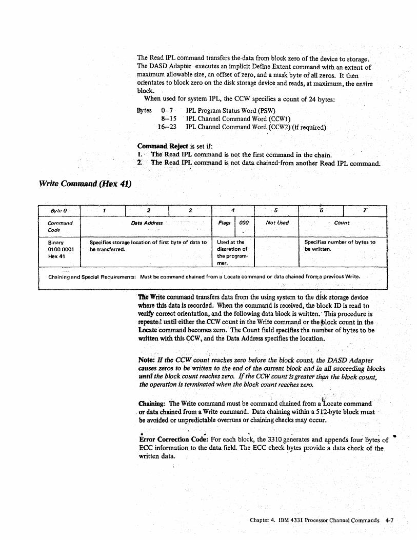
Write Command (Hex 41)
Byte 0 1 I 2 I 3 4 5 6 I 7·
Command Data Address Flags 000 Not Used Count Code
~
Binary Specifies storage location of first byte of data to Used at the Specifies number of bytes to 01000001 be transferred. discretion of . be written. Hex 41 the program-
mer.
. Chaining and Special Requirements: Must be command chained from a Locate command or data chained from...a previous Write .
\
. De Write command transfers data from the using system to the disk storage device where this 'data is recorded. When the command is received, the block ID is read to verify correct orientation, and the following data block is written.' This procedure is repeateJuntU'eiilier the.CCW count in the Write comman,d or the J>lock count in the Locate 'command becomes zero. The Count field specifies the number of bytes to be written with this CCW, and the Data Address specifies the location.
Note: If the CCW count' reaches zero before the block count, the DASD Adapter causes zeros to be written to the end of the current block and in all succeeding blocks until the block count reaches zero. If the CCW count is greater th{zn the block count. the operation is terminated when the block count reaches zero. ,~
Chaining: The Write command must be command chained from a tecate command . or data chained from a Write command.· Data chaining within a 512-byte block must . be avoided or unp_redictable overruns or chaining checks may occur.
... , . Error Correction Code: For each block, the 3310 generates and appends four bytes of ECe information to the data field. The Eee check bytes provide a data check of the written data.
Chapter 4. IBM 4331 Processor Channel Commands 4-7

Test I/O (Hex (0)
Bvte a 1 I
Command Reject is set if the Write command is chained from the Locate command and the adapter is not in the write state for this device.
Status: Write Without Verify (operation byte of the Locate command = Hex 01); channel end and device end are presented after the ECe bytes have been written for the last block.
Write With Verify ('operation byte of the Locate command = Hex 05); the DASD Adapter reads back all the blocks written without transferring any data, and compares the ECe bytes. Successful completion is indicated with channel end and device end.
Command Retry: If errors are encountered in this readback check, the DASD Adapter will retry the write operation. If the enor persists, unit check with permanent error (sense byte 1 bit 0) and check data error (sense byte 2 bit 0) will be indicated.
2 I 3 4 5 6 t 7
Command Data Address Flags 000 Not Used Count Code
Binary 0000 0000 Hex 00
Chai·ning and Special Requirements:
Used at the discretion of the program-mer.
None
Test 110 deterrri.ines the status of a disk storage device. It is the result of a programmed instruction or a self-initiated sequence by the using system. To the DASD Adapter, it is a command byte of zeros and is treated as an immediate
. ~ command. The execution of this command transmits one status byte to the using system in the initial selection sequence. -
Status Byte: The status byte presented can contain one of the following: • The available pending status bits. • A busy condition. • All zeros.
Sense I/O (Hex E4)
Byte 0 1 I 2 I 3 4 5 6 I 7
Command Data Address Flags 000 Not Used Count • Code ..
-Binary Specifies storage location where sense bytes are Used at the Seven 11100100 to be transferred. discretion of Hex E4 the program·
mer.
Chaining and Special Requirements: None
4-8 IBr-.J 3310 Direct Access Storage Reference Manual
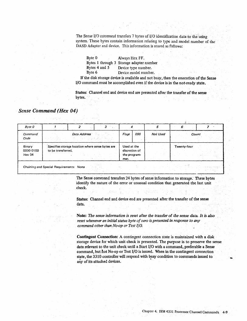
The Sense I/O command transfers 7 bytes of I/O identification data to the using system. These. bytes contain information relating to type and model number of the DASD Adapter and device. This information is stored as follows:
Byte 0 Always Hex FF. Bytes 1 through 3 Storage adapter number Bytes 4 and 5 Device type number. Byte 6 Device model number.
If the disk storage device is available and not busy, then the execution of the Sense I/O command must be accomplished even if the device is in the not-ready state.
Status: Channel end and device end are presented after the transfer of the sense bytes.
Sense Command (Hex 04)
,-- I I I Byte 0 1 2 3 4 5 6 7
Command Data Address Flags 000 Not Used· Count Code
Binary Specifies storage location where sense bytes are Used at the Twenty-four 00000100 to be transferred. discretion of Hex 04 the program-
mer.
Chaining and Special Requirements: Non.e
The Sense command transfers 24 bytes of sense information to storage: These bytes identify the nature of the error or unusual condition that generated the last unit check.
Status: Channel end and device end are presented after the transfer of the sense data.
Note: The sense information is reset after the transfer of the sense data. It is also reset whenever an initial status byte of zero is presented in response to any command other than_No-op or Test I/O.
Contingent Connection: A contingent connection state is maintained.with a ~sk storage device for which unit check is presen ted. The purpose is to preserve the sense data relevant to the unit check until a Start I/O with a command, preferable a Sense command, but flot No-op or Test I/O is issu:ed. When iiI the contingent connection state, the 3310 controller will respond with busy condition to commands issued to . any of its attached devices. '.
Chapter 4. IBM 4331 Processor Channel Commands 4-9
-
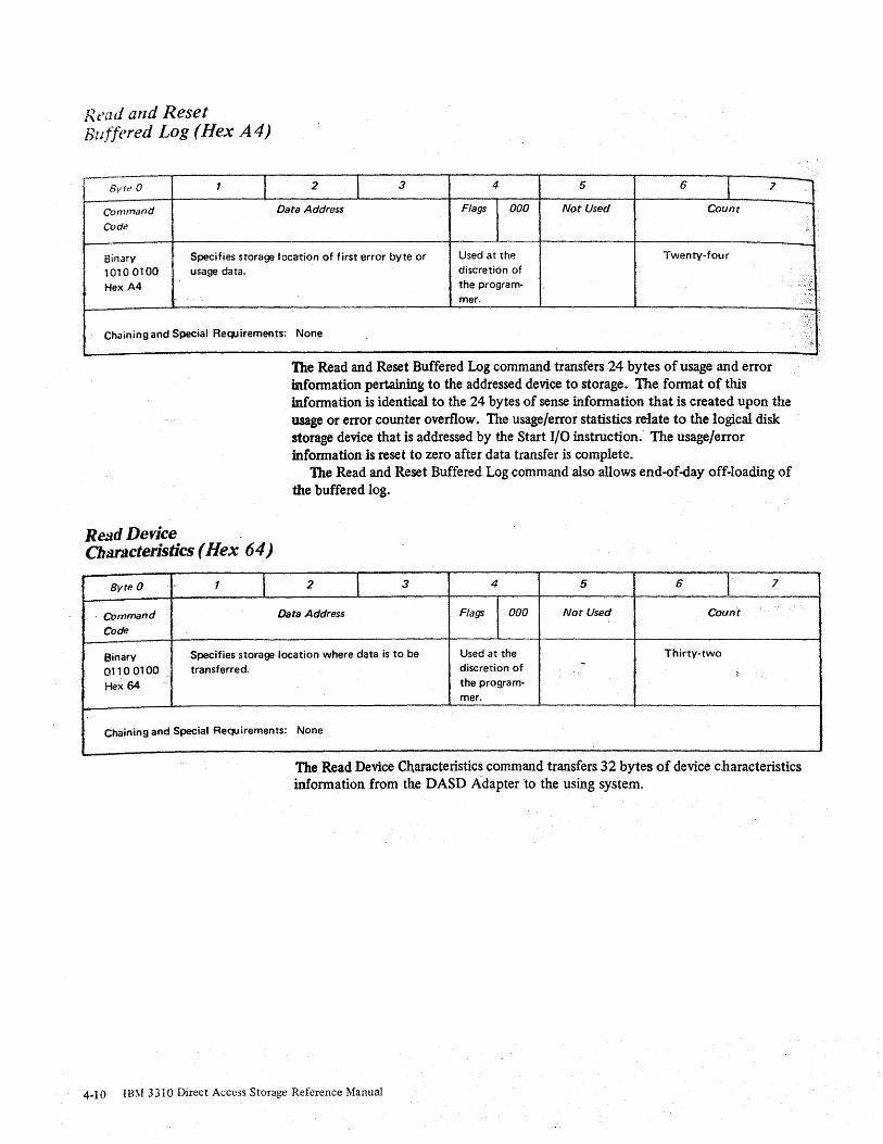
Read and Reset Buffered Log (Hex A4)
_. I Byft' 0 T 2 I 3 4 5 6
1 7
Command Data Address Flags 000 Not Used Count
Cod~
Binary Specifies storage location of first error byte or Used at the Twenty-four
10100100 usage data. Hex A4
Chaining and Special Requirements:
Relld Device Ch:UBcteristics (Hex 64)
Byte a l- T I
discretion of the program-mer.
None
The Read and Reset Buffered Log command transfers 24 bytes of usage and error information pertaining to the addressed device to storagew The format of this information is identical to the 24 bytes of sense infonnation that is created upon the usage or error counter overflow. The usage/error statistics relate to the logical disk storage device that is addressed by the Start I/O instruction: The usage/error information is reset to zero after data transfer is complete.
The Read and Reset Buffered Log command also allows end-of-day off-loading of the buffered log.
2 I 3 4 5 6 1 7
, Command Data Address Flags 000 Not Used Count
Code
Binary Specifies ~torage location where data is to be Used at the Thirty-two
Q1100100 transferred. discretion of -- - ,
Hex 64 - the program-mer.
Chaining and Special Requirements: None
The Read Device Characteristics command transfers 32 bytes of device characteristics infonnation from the DASD Adapter to the using system.
4-10 i8\f 3310 Direct Access Storage Reference Manual
....., ,,'
-
,:~~, :. 'c" .
:X; \ "
'.' ,

•
Bytes Contents
o 1 2 J
4-5 6--9
10-13 14-17 18 .... 21 22~23 24-25 .26-27 28-29 30-31
Operation modes X'30' Features X'08' Device class X'21' Unit type X'Ol' X'Ol' Physical record size (bytes) Number of blocks per cyclical group Number of blocks per access position Number of blocks under movable heads Reserved Reserved
. Number of blocks in CE area Reserved Reservedt
Reserved
Byte 0, Operation Modes
Bit Number
o 1 2 3
4-7
Byte 1, Features
Bit Number
o 1 2 3 4 5
6-7
Meaning
reserved not used o=- byte mode, 1 = burst mode 1 :: data chaining reserved
Meaning
reserved removable media shared device reserved movable access mechanism
. reserved reserved
X'0200t
X'OOOOO020~
X'OOOOO 160' X'OOOl EC40t
Diagnostic Control (Hex F3)
..
Byte 0 1 I 2 I 3 4 5 6 I 1
Command Data Address Flags 000 Not Used ~ Count Code
Binary Specifies storage location of first byte of Used at the Twelve or greater 1111 0011 diagnostic control parameters. discretion of Hex F3 . the progra!"- .
mer. . •
Chaining and Special Requirements: See description below.
The Diagnostic Control command transfers 12 bytes defming the exact operation to be perfonned) from storage to the DASD Adapter.
.
Chapter 4. IBM 4331 Processor Channel Commands 4-11

Format ID (Subcommand ID Hex 04~ .
The bytes are:
Byte
o 1
2-3 4-5
6 7
8-9 10 11
1\1eaning
sub·command ID must be X'OO' must be X'0008' block count must be X'OO' 3310 ID handling flag cylinder address head logical sector address
Sub-command ID
X'04' Format ID X'06' Space ID and Read Data X'OA' Read ID
Refer t9 the description of the'individual subcommands for the meaning of byte 7 -3310lD handling flag.
Logical Sector Address: All Diagnostic Control commands use a 4 byte logical sector address. Two bytes are used for cylinder address, one byte for head address, and one byte for sector address. The positions of logical sector 0 are shifted by eight sectors for each consecutive head, to allow for head switching time. Sector 32 however, is always the sector before the index pulse unless it has been displaced, see Defective Sector Handling in Chapter 2. Orientation for Diagnostic Control commands is done I on the sector counter, that is, counting, from index point to index point.
Command Reject is set if: 1. The subcommand code is other than hex 04, 06, or ~A. 2. Bytes 1, 3, or 6 are not as specified. 3. --For the subcommand Format 10, the preceding Define Extent did not allow
Format Write. 4.' The CCW count is less than 12. 5. Any of the other conditions given under the individual subcommands.
Status: See the individual subcommands. Access errors are retried by the DASD Adapter. If they are permanent, the
DASDA sets equipment check and 'permanent error in the sense data and terminates the, operation.
After the parameters have been verified, the subcommand causes the ID of the block specified by bytes 8-11 to be rewritten and the data field of the block to be filled with zeros.
4-12 IB~l 3310 Dire~t Access Storage Reference Manual

Space ID and Read Data • (SubcOOlmand ID flex 06)
Byte 7, the 3310 ID HandlingFlag, specifies how and wherethe ID is written as follows:
Bits 0-2 000 = 100 = 110
001
Write a normal ID Write an ID into the alternate area with the alternate flag on Write an ID into the alternate area with the alternate and defective flags on Write an ID into the sector behind 'the addressed one (next sequential) with the displaced flag on (see note)
010 = Write an ID with sector number 32 into logical sector 32 with the defective flag on (sector specification must be 32)
all Write an ID into the addressed sector with sector number32 and the defective and displaced flags on .
Bits 3-6: reserved (must all be zero) •
Bit 7: a = No function . 1 = Write the ID into the moved position (applies only when bits 0 ... 2 have the
patterns 110,010, and 011). .
Note: 1. If bits 0;.2 ate equal to 001 the next sequential sector is formatted, that is, the
sector defined by thtf contents of bytes 8-11 plus 1. 2. The Format ID command will not automatically be verified. A Read ID should
follow to check the ID and jf it fails, the Format ID should be retried. If the error is. permanent and the prime area is addressed? a format defective block procedure should be invoked. .
Command Reject is set if: I. The ID Handling Flag' byte is invalid. 2. Bytes 8-Hcontain an ~valid Ipgical sector address (a1temat~ not specified) for
the device. 3. Alternate specified, and bytes 8-11 contain an invalid alternate logical sector
address for the device. 4. Bytes 8-11 address a block in the CE area but the Define Extent mask bit 4 is
not set. 5. Bytes 8-11 do not address a block in the CE area but the Define Extent mask bit
4 is set on.
Status: Channel end, device end, and unit check are presented at the end of the data transfer if command ,reject is detected or if equipment check is set •
. The Space ID and Read Data subcommand orients to the block specified in bytes 8 - 11 and prepares the DASDA to space over the Block ID and to read the data field. Th!actu~l spacing over the 1D and reading the data fi~ld is performed on a subsequent Diagnostic Sense command X'C4'. Only one block is processed and the block count in bytes 4 and 5 is ignored.
3310 ID Handling Flag: Only bit 2 of byte 7 has any significance for this subcommand. If bit 2 = 1, the data is to be read from the sector behind the one addressed. All other bit combinations are ignored.
Chapter 4. IBM 4331 Processor Channel Commands 4-13
Read ID (Subcommand Hex OA)
Command Reject is set if bytes 8-11 do not contain a valid logical sector address for the device.
Status: If any sense bit in bytes 0, 1, and 2 is set, then channel end, device end and unit check are set. If not, then channel end and device end are presented when the block is reached.
Note: This subcommand may typically be used for recovering the data field of a block when the block ID has a permanent data check.
The Read ID subcommand prepares the DASDA to read one o-r more block lOs and accesses the first block. The number of block IDs that are read is determined by the block count in bytes 4 and 5.
The actual operation of reading the block IDs and transferring the data to the using system, is perfonned on a subsequent Diagnostic Sense command. The format of the bytes is identical to the block ID field written on the disk storage device. The block IDs processed are physically continuous.
Command Reject is set if the address in bytes 8-11 is not a valid logical sector address.
Status: . If any sense bit in bytes 0, 1, and 2 is set then channel end, device end. and unit check are set. If not, channel end and device end are presented when the block is reached.
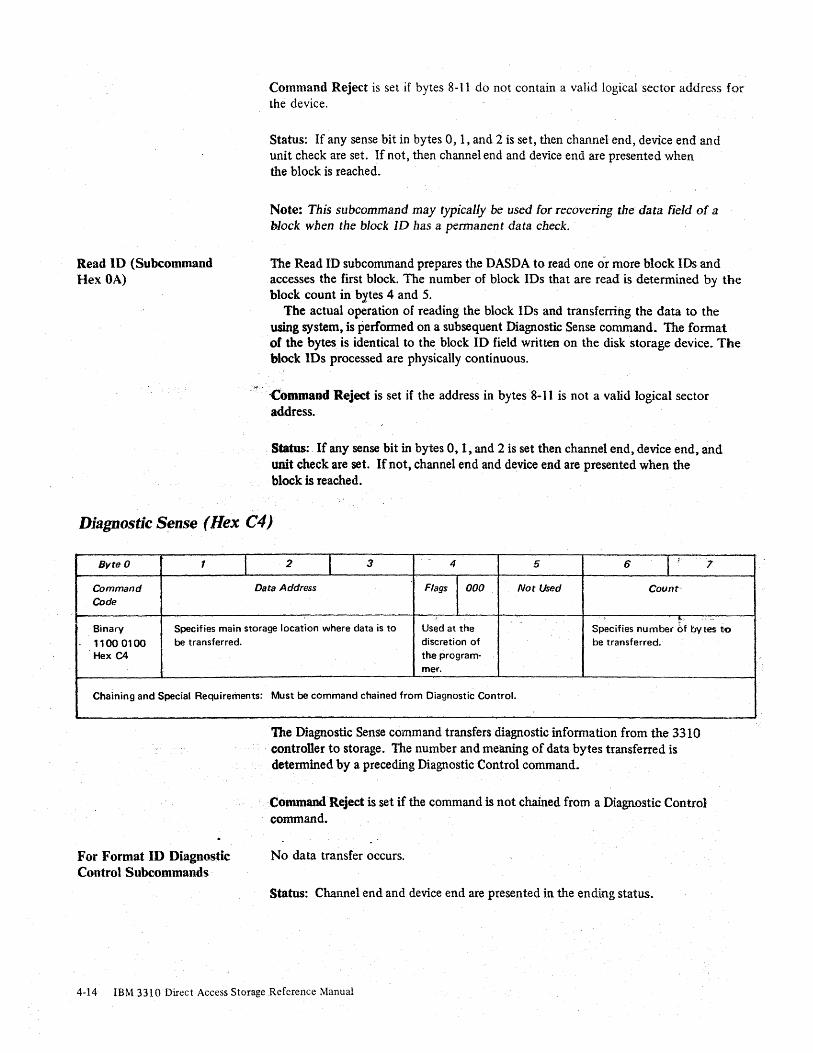
Diagnostic S~nse(Hex C4)
Byte 0 1 I 2 l 3 4 5 6 I 1 7
Command Data Address Flags 000 Not Used Count-Code
!' .. .-Binary Specifies main storage location where data is to Used at the Specifies number of bytes 110
11000100 be transferred. Hex C4
Chaining and Special Requirements:
For Format ID Diagnostic Control Subcommands
discretion of be transferred. the program-mer.
Must be command chained from Diagnostic Control. ,
The Diagnostic Sense command transfers diagnostic information from the 3310 controller to storage. The number and meaning of data bytes transferred is detennined by a preceding Diagnostic Control command~
Command Reject is set if the command is not chained from a Diagnostic Control command.
No data transfer occurs.
Status: Channel end and device end are presented in the ending status.
4-14 IBM 3310 Direct Access Storage Reference Manual

For SpaceID and Read Data Diagnostic Control subcommands
F or Read ID Diagnostic Control Subcommands
After orientation, allows the controller to space over the block ID field and transfer the 512-byte data field.
Retry: If a data error is detected during reading the data field~ the operation is retried. If the retries are unsuccessful, data check is set in the sense data.
Status: If any sense bit in bytes 0, 1, or 2 is set, channel end» device end, and unit check are set. At successful completion of the data transfer, channel end and device end are preSented.
After orientation, reads the 4 byte ID field and transfers it to storage. This process is repe.3ted until either the block count 97: the CCW count reaches zero. Access boundaries are ignored and the· controller continues reading IDs from· the same track.
The· block IDs are read from the disk as raw data, refer to the description in Chapter 2, Data Organization. '.
Retry: If a data error is detected in reading a block ID, the oper~on is retried. If.the error is permanent, the data check and ID data check sense bits ar-e set.
Status: If any sense bit in bytes 0, 1, or 2 is set, channel end, device end, and unit chec~are set. If not, channel end and device end are presented at the completion . of the data transfer .
Status: Channel end and device end are presented on completion of data transfer.
Chapter 4. IBM 4331 ProcessorClnmnel Commands 4-15

Chapter 5. Error R~overy
Error Condition Table
This chapter describes the error conditions that may occur within the 3310 and its associated adapter, and the recovery action procedures that should be used for each error condition.
The error condition table (Figure 5-1) summarizes error conditions that are identified in sense bit configurations set by the using system in sense bytes 0, 1, and 2. Each of these unique configurations requires a specific recovery action to be invoked by the system. Error logging requirements are also listed.
Bvte Bit Format Name Description Recovery
Action No. (see Figure 5-2)
a Q a Command Reject Programming error (see Note 11. 2
a a 0 Command Reject A Write command has been received with 1
1 6 Write Inhibit the device in the Read Only state. - "
a 1 1 Intervention Devic"e is offline. ~t; 3
Required
a 2 a Bus Out Parity Bus out parity error has occurred. 3
0 3 1 Equipment Check Equipment is malfunctioning. 4
0 3 1 Equipment Check Equipment malfunction (including access 1 1 a Permanent Error errod. Controller retry is exhausted or. 1
undesirable.
0 4 4 Data Check Uncorrectable data check. Controller 1 1 0 Permanent Error retry is exhausted.
0 5 0 Overrun Controller retry is exhausted on an - 1 1 0 Permanent Error overrun condition.
1 5 0 File Protected· A loc~te argument has violated the defirie 2 extent specifications.
2 3 6 Environmental Data Statistical usage/error log information is' 3 Present (see Note 3) present.
2 0 4 Check Data Error Permctnent data check during a write- \'Z~ ... ~~ 1 1 a Permanent Error verify operation. Controller retry is
exhausted.
0 0 0 Command Reject Alternate area is exhausted. 1 1 7 Operation Incomplete
0 4 5 Data Check logging mode data check. 21 2 3 Environmental Data
Correctable
0 4 4 Data Check logging mode data check. 21 2 3 Environmental Data
Uncorrectable
Notes 1. Command Reject is posted for any of the following conditions:
a. An Invalid command code.
b. An Invalid command sequence. c. The Invalid or incomplete argument has been transferred by a control command
d The Write portion of the inhibit mask, transferred bV a Define Extent command, has been violated.
e. The Alternate area is exhausted
Log
No
No
No
Yes
Yes
Yes
Yes
Ves
No
Yes
Yes
No
Yes
Yes
2. Detection of an overrun immediatelv stops data transmission. During writing, the remaining portion of the
data block is padded with lerOSe 3. During error logging mode, Data Check may be posted in conjunctiof1 with Environmental Data Present.
In all cases, Environmental Data Present dictates the action to be performed
Figure 5-1. Error Condition Table
Chapter 5. Error Recovery 5-1
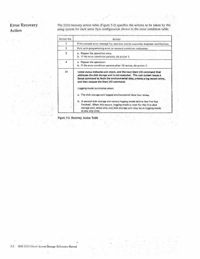
Error Recovery Action
The 3310 recovery action table (Figure 5-2) specifies the actions to be taken by the using system for each sense byte configuration shov,'n in the error condition table.
Action No. Action
1 Print console error message for operator and/or customer engineer notification.
2 Exit with programming error or unusual condition indication.
3 a. Repeat the operation once. b. If the error condition persists, do action 1.
4 a. Repeat the operation. b. I f the error condi tion persists after 10 retries, do ac tion 1.
21 Initial status indicates unit check, and the next Start 110 command that addresses the disk storage unit is not executed. The user system issues a Sense command to fetch the environmental data, creates a log record entry, and then reissues the Start I/O command.
Logging mode terminates when:
a. The disk storage unit logged environmental data four times.
b. A second disk storage unit enters logging mode before ~he first has finished. When this occurs,logging mode is reset for the first disk storage unit, since only one disk storage unit may be in logging mode at anyone time.
Figure 5-2. Recovery Action Table
5-2 IBM 3310 Direct Access Storage Reference Manual

Chapter 6. Sense Data
Sense Information Summary
Byte 0 1
0 Command Intervention Reject Required
Permanent 1 Error (Note 1)
Not Used
2 Check Data Correctabl e Error Data Check
3 · I
4 · I
5 •
6 I
The 3310 uses 24 sense bytes for identifying completely any condition that causes a unit check status to be generated. These sense bytes provide secondary information that may be required for system error recovery, or to aid the customer engineer to diagnose and isolate disk storage device and controller failures. The sense bytes also: • Indicate a usage or error counter overflow. • Logout error information if an error retry is successful during logging mode (see
Logging Mode.).
Sense bytes 0 through 7 contain high-level sense and condition data and have the same meaning for all fonnats (see Sense Formats, following). A summary of the· °t
o
sense information for bytes Othrough 7 is shown in Figure 6-1. .
Bit
2 3 4 5 6 7
Bus Out Equipment Data Check Overrun Not Used':: Not Used Parity (Not Used\ Check (Note 2) (Note 2)
Write ~f<.:i' Operation Not Used Not Used Not Used File Protected Inhibited Incomplete
Not ·Used Environmental Not Used Not Used Not Used Only Logging Data Present Required
Physical Cylinder Address (High Order) I I I . . I I I I I
Physical Cylinder Address (Low Order) I I I . I I
I I
Physical Head Address • . p . . t · . r .
Physical Sector Address .·k ... ,
I L , I I I
ft 7 Format Number (bits 0-3 hex) Message Code (bits 4-lh~x)
Notes: 1. Set by ERP'S 2 Usually indicates a 3310 malfunction if
byte 7, bits G-3equal '1', '4', or '5'.
Figure 6-1. Sense Data Summary (Bytes 0 through 7)
Otaptc( 6. Sense Data 6-1·

Sense Bytes 0 through 2
Sense byte 7
Message Code (bits 4-7 hex.) Format Number (bits 0-3 hexJ
U Format 0 Format 1 Format 4 Format 5 Format 6
Hex (Programming or (Device Equipment (Uncorre<:table Data (Correctable Data (Usage and Error
f----'-System Che<:ks) Checks) Checks) Cheeks) Statistics)
0 No Message No Message 10 Field Data Check No Message Read and Reset Buffered Log·
f---Overflow of
Transmit Target Data Field Data 1 Invalid Command Error Check Blocks Read
Counter --...,--..
Overftowof 2 Invalid Sequence Microcode Not Used Data Checks Detected Errors
R et ... ied COU:flter - Overflow of CCW Count LesS 3
Than Required Correctable Data - . Checks. Counter -
ID Field NQ Sync Overflow of Btocks 4 Invalid Parameters Byte Found . Written with
'--Verify. Gaunter
Block Not Within Unexpected Data Field No Sync Overflow of
5 Status at Initfaf - Check Data the Valid Extent Selection
Byte Fq~nd Errors Counter - Ove·rflowof
6 Not Used Cylinder Address Not Used Access Motions Err<!r Counter ----- OverflQwof
7 Not Used Acees$ Errors
- Co.unter ..
8 Not Used Not Used
----- File Status Not as 9 Not Used Expected During Not Used
Read IPLor Retry >--
A Not USed ' Seek Error at Seek Not Usid Verification
f---....;-
B Not Used Seek Error at .Not Used Recal rbratjon
f---~
C Space in Alternate No Interrupt from Not Used Area Exhausted Drive
-D Data Overrun Not Used
i----
E Not Used Not Used
~
F Not Used Not Used
'---
Figure 6-2. Format Messages Summary (Sense Byte 7)
Sense bytes 0 through 2 are only generated when a unit check occurs. These bytes describe the error cpndition and identify the action needed to effect error recovery (see Error Recovery. section). The unit check .infonnation-generated can be any of the following.
6-2 IBM 3310 Direct Access Storage Reference Manual

S2nse Byte 0
Sense Byte 1
Sense Byte 2
Bit 0: Command Reject is set when an unknown command is received, or when a command violates the required sequence or prerequisite. For example:
• The Derme Extent mask prohibits the operation. • A Read or Write command is not chained from a Locate command. • Replication count is not an integral multiple of block count.
Bit 1: Intervention Required is set when the addressed disk storage device has no power or is not attached.
Bit 3: Equipment Check is set when a hardware error is detected in the disk storage device or the adapter in the using system.
Bit 4: Data Check is set when an error is detected in the data received from the disk storage device,and when the automatic retry by the adapter in t}}e using system is unsuccessful. A data check indicates that read ID fields cannot be tead without-eRe checks or data fields read without ECC checks. The affected~D or data field is define9- in a format 4 message.
Bit 5: Overrun: When a data request of the adapter in the using system is not granted within a specified time limit, a potential overrun condition is detected that causes automatic retry attempts. If the overrun condition exists on the final retry, overrun is posted and data transfer is stopped. The remainder of the recor4 is padded with zeros if a Write command is being_executed.
Bit 0: Permanent Error is set when an error persists 'after the adapter in the using system has exhausted its automatic retry attempts.
Bit 5: File Protected is set when a Locate or Diagnostic Control ccJlnmand violates the logical extent limits est~blished by the Define Extent command. Writing is then suppressed. ,.
Bit 6: Write Inhibited is set if writing is attempted on a record when the ID field has one of the write·protect flags (field 1) set to On.
Bit 7: Operation Incomplete is set when an operation ends pretnaturely. For example, when Fonnat Defective Block is specified and all alternate space ilexhausted.
Bit 0: Check Data Error is set when an error is detected during the automatic read. -back checlt operation that follows writing when Verify_has been spe~ified~ and retry,
attempts by the adapter in the using system have been unsuccessful.
Bit 1: Correctable Data Check indicates that the indicated data check or check data error is correctable. This bit is only set when the device is in logging mode.
Bit 3: Environmental Data Present is set when sense bytes 8 through 23 contain usage or error counter information (log statistics).
Olapter 6. Sl!nse Data 6-3

Sense Bytes 3 through 6
Sense Byte 7
Sense Formats J~':
Logging Mode'
Bit 7: Only Logging Required is set if an error occurs that should be logged to preserve data without invoking error recovery actions, when the disk storage device is used with emulation. The operation performed is similar to that done for Environmental Data Present.
Sense bytes 3 through 6 contain the physical address being accessed at the time the error was detected. The content of these sense bytes are as follows: • Bytes 3 and 4 contain the physical cylinder address.
Sense byte 3 contains the high order cylinder address of the most recent seek operation. Sense byte 4 contains the low order cylinder address of the most recent seek operation.
• Byte 5 contains the physical head address. Sense byte 5 identifies the head that was last used,. wruch·is usually the head address of the most recent seek or, when head switching was involved, the update of that address.
• Byte 6 contains the physical sector address. Sense byte 6 contains the seCtor address that identifies the sector defined by relative displacement in the most recent byte command.
Sense bytes 3, 4, 5, and 6 are unpredictable in Fotroat 6. _
Sense byte 7 identifies the format of sense bytes 8 through 23. • Bits 0 through 3 identify the format of sense bytes 8 through 23. • Bits 4 through 7 provide an encoded message that describes the error condition.
The codes ·are related to format and are described in the following pages ..
Sepse bytes 8 through 23 contain format dependent information. The formats used by the 3310 are as follows: • Format 0, for programming or system checks. • Format I, for device equipment checks. • Form'!t 4, for data checks not providing ~orrectioninformation. • Format 5,' for data checks providing correction information. • Format 6, for usage and error statistics.
Each of the formats concerned with the 3310 is sUIllIilarized in Figures 6-3 through 6-9. Figure 6-2 contains a summary of the applicable messages for each of the formats. If the indicated format is 2 or 3, refer to the 4331 Processor Functional Characteristics (see Preface).
Logging mode occurs when the error counter of a disk storage device overflows before the corresponding usage counter overflows (refer to Chapter 7 for more . information on Usage, Error, and Overflow counters). Usage, error,. and overflow counters are then offloaded and initialized.
If a disk storage device is in loggiilg mode, and encounters a successfully retried error of the s~me type that caused it .to enter logging II\<?de,.then 24 sense bytes of environmental data (Sense byte 2, bit 3 active) are collected by microcode.
The following formats are used when logout occurs due to an error condition. • Fonnat 1, if the error is a seek error. • Format 4, if the error is a data check retried. • Format 5, if the error is a correctable data check.
6-4 IBM 3310 Direct Access Storage Reference Manual

'Bytes 8 through 23
Formirt 1
Byte Formirt 0 Not Message Message 'A' Format 4 Format 5 Format 6 'A' (No Seek (Seek Check) Check.
Control Actual Seek 8 Interface Address
Bus Out (Cylinder\ ~.,-
Control Actual Seek Number of Blocks 9 Interface Address Read (see Note 3)
Bus In (Cylinder\ f----
Control Actual Seek 10 Interface Address
Tag 8us (Head\ -11 Not Used Controller Status Not Used Not Used
Number of - Correctable Data
Controller Checks 12 Error Byte 1
r--Controller Not Used Number of Data
13 Error Byte 2 Checks Retried
r---
14 Controller Error Byte 3 Not Used
15 Drive Sense
Number of Block.s 16 Diagnostic Sense 1
Number of Blocks Written with Verify
Number of Good NUmber of Good (see Note 4\ Blocks Transferred Blocks Transferred Transferred Including
Error Block 17 Diagnostic Sense 2
18 Diagnostic Sense 3 Number of Check Data Errors Recovered
Error- Displacement DCIA- File Not
19 Sense Register Used Relative Block Relative Block
Number of First Number of Access Number of First Failing Block Failing Block (see Motions (Seeks\
DCIA- File Not Note 1\ 20 Control Regist(' Used
Error Pattern
21 Microcode Detected Number of Access Errors (see Note :n Errors
--
22 Number of Service Overruns
Not Used Fault Symptom Code Fault Symptom Code Not Used
23 Not Used
Notes:
1. These bytes contain the number of blocks from the beginning of the data set that the first block to be processed is displaced. 2 The Microcode error condition is encoded as follows:
Hex
o Not used 1 No Tag Valid on ReadlWrlte operation
Hex 8 Notused 9 Notused A Incorrect drive selected 2 No normal or check end on Read/Write operation
3 No response frd'm controller on control operation 4 Not used
B Busy condition (s~ek incomplete) missing after s~ek start was issued C No block found
5 CRC compare logic check duritng feed.back of D Control Bus In pacity check CRCbytes
6 More than one controller selected or non-selected E Always active bit on Bus In. 7 Preselection cheCk F Unresetable interrupt
3. These bytes provide an accumulated count of the number of blocks (512 bytes) processed by the adapter in the user syst9m in Read operations.
4. The blocks written have automatic verification through a read back check.
Figure 6-3. Sense Data Summary (Bytes 8 through 23)
01apter 6. Sense Data 6-5

~FOlmat 0 Format 0 is generated for programming or system checks. --"0 _____
Bit Byte
0 I 1 I 2 I 3 J 4- 1 5 1 6 I 7
8 Not Used
9 Not Used
10 Not Used
11 Not Used
12 Not Used
'-13 Not Used
14 Not Used ,
15 Not Used -
16 Number (in Hex) Good, Blocks Transferred
17 Number (in Hex) Good Blocks Transferred
18 Relative Block Numbe-F (in Hex) of First Failing Block
19 Relative Block Number (in Hex) of First Failing Block
~ h _~_ _. --, i 20 Relative Block Number (in Hex) of First Failing Block .. .;
21 Relative Block Number (in Hex} of First Failing Block
22 Not Used
23' Not Used
-Figure 6-4. Sense Data (Bytes 8 through 23) ~ Format O.
F onnat 0 Messages Message 0: No message is generated ifno additional information is required.
6-6 IBM 3310 Direct Access Storage Reference Manu.al

Message 1: Invalid Command is generated when a comma.nd that is not in the command set is issued to the adapter of the using system~
Message 2: Invalid Sequence is generated when an invalid sequence of commands has occurred. This includes the following:
• Define Extent prerequisites are not satisfied by a Write command~ any Diagnostic command, an additional Define Extent command.
• A Locate command is not preceded by a Define Extent, or a Read IPL command in the same command chain.
• A Read command is not chained from a Locate command. • A Read command is chained from a Locate command and the adapter in the
using system is not read-oriented for this device. • A Write command is not chained from a Locate command. • A Write command is chained from a Locate command and the adapter of the
using system is not write oriented for this device. • A Device Reserve or a Device Release command that is preceded by a Define
Extent in the same command chain. • A Diagnostic Control command that is not preceded by a Define Extent
command. -• A Diagnostic Sense command that is not preceded by a Diagnostic Control
command. --
Message 3: CCW Count less than Required is generated when-the CCW count for a:. • Define Extent command is less than 16. • Locate command is less than 8. • Diagnostic Control command is less than 12.
Message 4: Invalid Parameters is generated when parameters iJf a command are . invalid. This includes: ,,' • Define Extent parameters are invalid for the addressed device. • Locate block .count parameter contains a value of zero. • Locate operation byte contains an unused operation code.
Message 5: Block not within the Valid Extent is generated if any block specified by the block count is outside the parameters of a Locate command.
Message C: Space in Alternate Area Exhausted is generated when, at the execution of a Format Defective Block operation, the space in the alternate 'area has been exhausted.
Message D: Data Overrun is generated when a response to a -data request signal is not received by tIte adapter o! ·the using system within the sp~cified time, after ten Data Overrun retries have proved to be unsuccessful.
Notes: 1. Except for Message 5 and Message D, alI messages of format 0 are set in
conjunction with Sense Byte 0, Bit P (command reject). 2. Message 5 is set with Sense Byte 1, bit 5 (file protected). 3. Message D is set with Sense Byte 0, bit 5 (overrun) and Sense Byte 1, bit 0
(permanent error).
Chapter 6. Sense Da.ta 6· 7

!?QrmatliNo Seek Check) Format 1 is generated fOLdevice,equipmentcheceks-and is-available in twoforms;-No Seek Check, and Seek Check. If message A is indicated in the message bits, use- the Format 1 (Seek Check) Sense data.
Bit Byte
0 1 2 3 4
Control Interface Bus Out 8
Bus Out 0 Bus Out 1 Bus Out 2 Bus Out 3
9 8us In 0 Bus In 1 Bus tn 2 Bus In 4
Control Interface Tag Bus 10 Tag Bus 0 Not Used Tag Bus 4
Controller Status 11 Not Used Not Used Not Used
Controller Error Byte 1 12 Tag Bus C$RVD Sector Not
Parity Error Too Late Count Error Used
Controller Error Byte 2 13 Sync Byte Bus/In Serial Parity Gap Counter
Error Bit 0 Out Parity Check Check
Controller Error Byte 3
14 Bit Ring Write Gate Not Error Check Used
Drive Sense
15 FHD Command * Data * Not Select Error Unsafe
Index and Diagnostic Sense 1 16 On Track ' Sector Pulses Out Direction Not Out Drive
Missing
Behind Not Missing
17 Clocks Error Home Latch
18 Not Shift Inside AGC Not (Read ,~ Window and Write)·
19 Select Normal CE. Active End Alert
DCIA - File Control Register 20 Not Used Tag
Gate
Microcode Detected Errors 21 Not Not Error Error Error Error
Used Used Code 32 Code 16 Code 8 Code 4
22 Fault Symptom Code
23 .. Fault Symptom Code
. Bytes 15-18are DSD (disk storage device) sense and status bytes. "(he bits marked with a-" asterisk·(*) are error conditions' that cause an interrupt when seek incomplete is reset. The remaining bits of these bytes indicate the DSD status at the'instant the sense operation took place.
Figure 6-5. Sense Data (Bytes 8 through 23) - Format 1 (No Seek Check)
6-8 IBM 3310 Direct Access Storage Reference Manual
6 7
Bus Out 7
Bus In 7
Tag Bl./s 7-
Sector Found
Not Used
CRC/ECC HardwEtre Check
Continuity Continuity Check, Sel'd Check.OSD DSD Cable Ctl Bus Cable
Home Not *' Ready
Tag Parity Velocity Error Profile Error
Not Missing Counter 5 PES In Sync
Not (Servo Protect and lIIegr Write) Mov
Error File Bus-In Alert Parity CK
Recycle
Error Error Code 2 Code 1

Format 1 (Seek Check)
Byte 0 1
I 8
I I
9
I t
10
t 11 Not Not
Used Used
12
I I
13
I 1
14
L 15 FHD I Brake*
Not Select Applied
16 -_ .. _-
Normal and On Track
If message A is not indicated in the message bits, use Format 1 (No Seek Check) Sense data.
Bit
1 2 3 1 4 5 6 7
I I I I I , Actual Seek Address (Cylinder)
1 II I I t I I I I I I
Actual Seek Address (Cylinder)
t t I I t t I I I I I 1
Actual Seek Address (Head! I 1 I I 1 t
Controller Status I Nett Not I Not Not Device Sector Used Used Used Used Interrupt Found
I l Not Used
I I I I I I I I I. 0 I I :- I
Not Used
I i I 1 I f I I I- I f _ I
Not Used j I I I I 1
Drive Sense
(Home I Track* I Command* . -toata* I Seek INot. Unavailable Error Unsafe Incomplete Readv
Index and Diagnostic Sense 1 . I Linear Region
Even I Sector Pulses
Missing lout Direction I Not Out Drive J Not In Drive ITag Parity
Error ::" f Velocity
Profile Error
~ I Not Mi$$lng . Diagnostic Sense 2 17 Behind I Two Missing Clocks Error I Coil Cu rrent I Missing Servo I Off Data
Home Clocks Latch low Signal Track
Diagnostic Sense 3 18
Not Shift t Not (Off Track I Inside AGC I Not AGC I Demod Not (Read ar.d Writel Window Freeze., Pulsing and Writel
I I I t 19 Not Used
I I I I 1 - .
I I I I I 20 Not Used
I I I I I . Microcode Detected Errors
21 Not l Not Error Error I Error Error Used Used Code 32 Code 16 CodeS Code 4
I I 22 Fault Symptom Code
1 I I I I I I I I I
23 Fault Symptom Code
I I I I- I
Bytes 15-:-18 are DSD (disk storage device) sense_ and status bytes. The bits marked with an asterisk (*) are error conditions that cause an interrupt when seek incomp/(~te is reset. The remaining bits of these bytes indicate the DSD status at the instant the sense operation took place.
Figure 6-6. Sense Data (Bytes 8 through 23) - Format 1 (Seek Check)
I Not Missint'_ Courrter 5 I-
PES In Sync
Not (Servo{-Protect a~Ji.:- Illegal Writel ~ Mov~
t._
I f I I
t f
Error Error Code 2 Code 1
0-
I "' J I l
I t
Chapter 6. Sense D-'.lta 6-9

Format 1 (Seek Check) . If message A is not indicated in the message bits, use Format 1 (No Seek Check) Sense data.
S'{ta
8
9
10
11
12
13
14
15
16
17
18
19
20
21
22
23
0
Not Used
FHD Not Select
On Track
Behind Home
Not Shift
Not Used
Inside AGe WindQw
Bit
4
Actual Seek Address (Cylinder)
Actual Seek Address (Cylinder)
Actual Seek Address (Head!
Contrail er Status Not"' Used
Not Used
Not Used
Not Used
Drive Sense Command· Error
Data* Unsafe
Diagnostic Sense 1
Not Used
5
Seek Incomplete
Out Direction Not Out Drive Not In Drive
Diagnostic Sense 2 Coil Current' Mi:$ing Servo Low Signal
Diagnostic Sense 3 Not AGC Derned Freeze~ ... Pulsing
Not Used
Microcode Detected Errors Error CodeS
Off Data Tra£k
Not {Read and Write)
Device Interrupt·
Home
Not Missingf PES
Not (Servo i
Sector Found
Not * Ready
7
Velocity Proffle Error
Counter 5 In Sync
Illegal Move
Error Code 1
'.
Bytes 15-18 are DSD (disk :torage device) sense and status bytes. The bits marked with an asterisk (*) are error conditions that cause an interrupt when seek incomplete is reset. The remaining bits of these bytes indicate the DSD status at the instant the sense operation took place.
Figure 6·6. Sense Data (Bytes 8 through 23) - Format 1 (Seek Check)
OIapter 6. Sense Data 6-9

Format 1 1\-lessages Up to sixteen messages are defined and printed in the EREP summary statistics.
Message 0: No message is generated if no additional information is required.
Message 1: Transmit Target Error is generated when a readback check of the disk storage device target register detects that the target register was improperly loaded on a Set Sector operation.
Message 2: Microcode Detected Errors is generated if errors are detected by the micro~ode as defmed in Sense Byte 21.
Message 5: Unexpected Drive Status at Selection is generated when the subsystem receives a status that is not an expected condition during device selection . The following unexpected conditions may be found: ' • Device not attached (no tag valid). • Device offline. • Device unsafe.
Message 6: Cylinder Address Error is generated after a readback of a target cylinder number ranging from 0 to 255 (~equired address) by Diagnostic Interface Wrapback detects that the disk storage device was improperly loaded on a seek operation.
Message 9: File Status not as Expected during Read IPL or Retry is generated when the adapter of the using system does not receive the' expected file status during the internal rezero. of the Read IPL command or during execution of Command Retry requiring the use of Set Sector.
Message A: Seek Error at Verification is'generated when seek verification detects a wrong cylinder or head address.
Message B: Seek Error-at Recalibrate is generated if after;the execution ofa Recalibrate during Seek retry no home indication is detected, or track unavailable is indicated.
Message C: No Interrupt from Device is generated when the adapter of the using system does not receive an interrupt from the disk storage device within a specified time. This condition can only occur on an internal seek or recalibrate while the disk storage device remains connected with the adapter.
, 6-10 IBM 3310 Direct Access Storage Reference Manual

I I I
hormat4 Format 4 is generated for data checks that do not provide correction information.
S.it Byte
0 l 1 I 2 f 3 t 4 I 5 I 6 I 7
I I I r , I 8 Not Used·
I I I I I I I , I I I I I
9 Not Used 1 I I I I I I , I I I: I I
10 Not Used I I I I I I I I I f I I I
'1 -Not Used I l I 1 t , I ~r , I "I , T
12 Not Used I I. I , I I I 1 I· , f I , I
13 Not Used .1 I I I .1 I I
J I 1 I . t
14 • ~ Not· Used
I I. I J , I 1 , I T -I t t
15 Not Used 1 I I I t I t , t , 1 , , I
16 Number (in Hex) of Good Blocks Transferred , I I I .,
f t I , I T I . I f
17 Nuniber (in Hex) of Good Blocks Transferred
• L I . I I , • I , I I I • t
18 Relative Block Number (in Hex) of First Failing B.lock I I I. I ) . I 1 I . . I T I , I
19 Relative Block Number (in Hex) of First Failing Block
• 1 I I .,
I I I . , I I , I •
20 R.lative 8.10ck Number (In Hex) of First Failing Block I r I I I t t I I
Relative' Block Number (i~ Hex) of First Fa~ling Block 1 t
21 t I t I I f I J I I I I· , I
22 "' ". ·--ault Symptom Code d .-
I .1 I I I I I t I I I I t
23 Fault Symptom Code ~
I ..l r J J J I
Figure 6-7. Sei~-Data (Bytei"S ltlrough 23)" '- Format 4
Format 4 Messages These messages are printed·in the EREP summary statistics.
Message 0: ID Field Data Check is generated when a CRC data check occurs in an ID field. Irt this case the Format Defective Blockprocedure should be applied to the defective block.
Message 1: Data Field Data Check is generated when an Eee data check occurs in the data fiel*
Message 4: ID Field· No Sync Byte Found is generated when synchronizatioq on the ID area was unsuccessful.
Message 5: Data Field No Sync Byte Found is generated when synchronization on the Data area was unsuccessful.
Chapter 6. Sense Data 6-11"

Formtat 5
Byte
f 0 1
f 8
I I
9
I I
10
I I
11
I I
12 , I
13
I I .
14
I I
15 , I
16
f .- . I
17 , I
18
I I
19--
I I
20 I I
21 I I
22 I I
23 I
Format 5 is generated for data checks that provide correction information. It is only offloaded to the system when Error Logging 1V1ode is on.
Bit
I 2 r 3 I 4 I 5 r 6 T 7 I I I I I T
Not Used
1 I . J I , I I I I I I T
Not Used , I I I I I I I I I [ I
Not Used
I , I , I r I I , I I 1
Not Used
I I I I r I I I I I 1 I
Not Used
I I I , t r I I I .. I I I
Not Used
I I I I , I I I I I 1 I
Not Used
I t I I I I I I I I I I
Not Used
I I I I I , I I I I I t
Number of Blocks (in Hex) Transferred including Error Block
I I I I I r I I I I T I
Number of Blocks (in Hex) Transferred including Error Block
I . I I I 1 '(
I I I I , I Error Displacement
I I I , I f I I I I , I
Error Displacement
1 - I I . I I I I . I I I 1 j
Error Pattern , I I r I , ' I I I I I I
Error Pattern
I I I .1 , f I l I I ~ l
Not Used
t I J { I 1 I I I' I -r 1
Not Used
I I .1 I , I
Figure 6-8. Sense Data (Bytes 8 through 23) - Format 5 . . . Format 5 Messages Message 0: No message is generated if no additional information is required.
6-12 IBM 3310 Direct Access Storage Reference Manual

Format 6
Byte , 0 , 8 ,
I 9
I I
10
I , . 11
I I
12
J .. 13
I t
14
J I
15
I I
16
I . .1 17
I I
18
I I
19
J I
.~O
I I
21
I .. , 22
I I
23
I
1 I I
Fonnat 6 is generated when either a counter overflow occurs or in response to a Read and Reset Buffered Log command. Then, the Usage/Error statistics need to be offloaded to the operating system. The counter information is reinitialized after offloading. The Usage/Error statistics have to be offloaded before the machine is powered off. The values given in Fonnat 6 bytes are in hexadecimaL
Bit
2 I 3 I 4 I 5 I 6 I 7 I I I T . 1
Number of Blocks Read
I I I I I f I I I These bytes provide ao accumurated (
count of the number of 512 bytes Number of Blocks Read processed by the using system DelA in
I I I read operations. ,
I I I I , '. Number of Blocks Read
I I I I f , I I I .~ 0' I r I
.. Number of Correctable Data Checks
I I I I I J I I I 1 r I
Number of Correctable Data Checks
t I I I I 1 I • I I I I
Nllmberof Data Checks Retried
I I I I I 1 t I I I I I
Not Used
J t t. 1 . , t"
I t I I T l Number of Blocks Written with Verify
I t 1 1 I I I I 1 1 1 1
Number of Blocks Written with Verify
I , I , I I I I I I [ I \
Number of Blocks Written with Verify
I I .. I I I I I I I I I I
Number of Check Data Errors Recovered . , f ,. _. I J I I l , , I ,
Number of Access Motions (Seeks)
I J. 1 I ( t I I I I I 1
Number of Access Motions (Seeks)
I I I J f I I 1 I I l I
Number of Access Errors
I J I I f f . I I I I· .. l I
Number of Service Overruns .. I- .1 I -1 r I I I I ·1 1 I
Not Used
I I I J t J
Figure 6-9. Sense Data (Bytes 8 through 23) - Format 6
Chapter 6. Sense Data 6-13
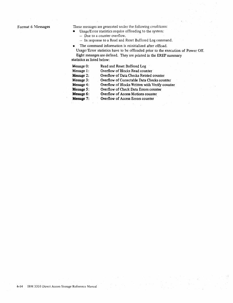
Format 6 r\rlessages These messages are generated under the following conditions: • Usage/E rror statistics require offloading to the system:
- Due to a counter overflow. - In response to a Read and Reset Buffered Log command.
• The command infonnation is reinitialized after offload. Usage/Error statistics have to be offloaded prior to the execution of Power Off. Eight messages are defmed. They are printed in the EREP summary
statistics as listed below:
Message 0: Message 1: Message 2: Message 3: Message 4: Message 5: Message 6: Message 7:
Read and Reset Buffered Log Overflow of Blocks Read counter Overflow of Data Checks Retried counter Overflow of Correctable Data Checks counter Overflow of Blocks Written with Verify counter Overflow of Check Data Errors counter Overflow of Access Motions counter Overflow of Access Errors counter
6-14 IBM 3310 Direct Access Storage 'Reference Manual
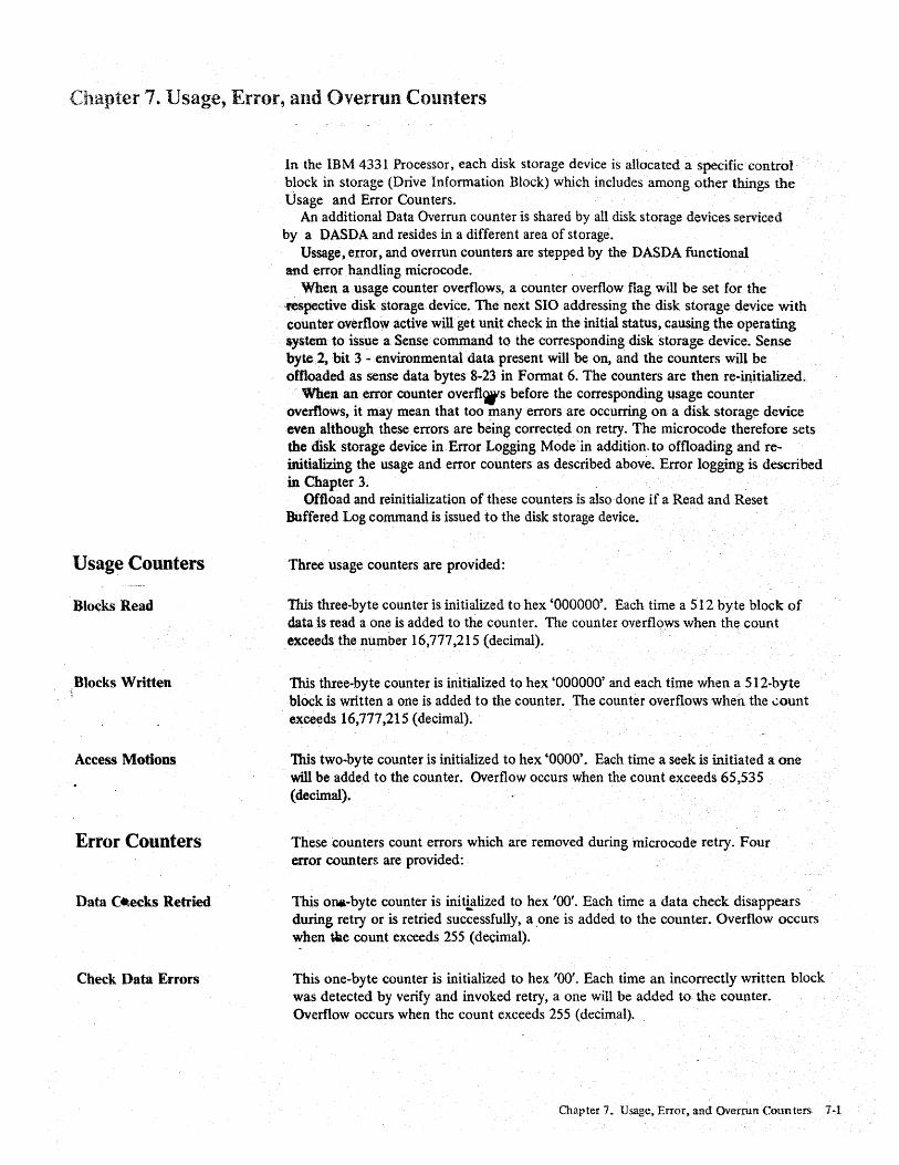
Chapter 7. Usage, Error, and Overrun Counters
Usage Counters
Blocks Read
Blocks Written
Access Motions ..
Error Counters
Data 01lecks Retried
Check Data Errors
In the IBM 4331 Processor, each disk storage device is allocated a specific control block in storage (Drive Information Block) which includes among other things the Usage and Error Counters.
An additional Data Overrun counter is shared by all disk storage devices serviced by a DASDA and resides in a different area of storage.
Ussage, error, and overrun counters are stepped by the DASDA functional and error handling microcode.
When a usage counter overflows, a counter overflow flag will be set for the -feSpective disk storage device. The next SIO addressing the disk storage device with counter overnowactive will get unit check in the initial status, causing the operating system to issue a Sense command to the corresponding disk storage device. Sense byte.2, bit 3 - environmental data present will be on, and the counters will be ofOoadedas sense data bytes 8·23 in Format 6. The counters are then re-in,itialized.
'When an error counter overfl'4t's before the corresponding usage counter overflows, it may mean that too many errors are occurring on a disk storage device even although these errors are being corrected on retry. The microcode therefore sets the disk storage device in Error Logging Mode' in addition. to offloading and reinitializing the usage and error counters as described above. Error logging is described in Chapter 3.
Oftload and reinitialization of these counters is also done if a Read and Reset Buffered Log command is issued to the disk storage device.
Three usage counters are provided:
This three-byte counter is initialized to hex '000000'. Each time a 512 byte block of data:is read a one is added to the counter. The counter overflo:ws when th~ count exceeds the number 16,777,215 (decimal).
This three-byte counter is initialized to hex '000000' and each time when a 512-byte block is written a one is added to the counter. The counter overflows when the ~ount exceeds 16,777,215 (decimal).
This two-byte counter is initialized to hex '0000'. Each time a seek is initiated a one will be added to the counter. Overflow occurs when the count exceeds 65,535 (decimal).
These counters count errors which are removed during microcode retry. Four error counters are provided:
This oIl4l-byte counter is initialized to hex '00'. Eac~ time a data check disappears during retry or is retried successfully, a ,one is added to the counter. Overflow occurs when t.ke count exceeds 255 (decimal).
This one-byte counter is initialized to hex '00'. Each time an incorrectly written block was detected by verify and invoked retry, a one will be added to the counter. Overflow occurs when the count exceeds 255 (decimal).
Char)ter 7. Usage, Error, and Overrun Counters 1-1

Access Errors
Correctable Data Checks
Service Overrun Counter
This one-byte counter is initialized to hex '00'. Each time a seek error (physical address mismatch) is retried successfully, a one is added to the counter. Overflow occurs when the count exceeds 255 (decimal).
This two-byte counter is initialized to hex '0000'. Each time when a correctable data check is eliminated by correction, a one is added to the counter. Overflow occurs when the count exceeds 65,535 (decimal).
This one-byte counter is shared by all disk storage devices served by one DASDA. It is initialized to hex '00'. Each time a data overrun occurs a one is added to the counter, except in retry mode.
When the counter overflows (increased beyond 256) it will be set to hex 'FF' and further updates will be inhibited. After the Usage, Error and Overrun Counter offload, the service overrun counter will be reinitialized to hex ~OO'.
7-2 ·IBM 3310 Direct Access Storage Reference Manual
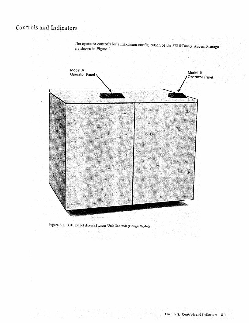
Controls and Indicators
The operator controls for a maximum configuration of the 3310 Direct Access Storage are shown in Figure 1.
Model A Operator Panel
Figure 8-1. 3310 Direct Access Storage Unit Controls (Design Model)
ModelB
./operator Panel
Chapter 8. Conttolsand Indicators 8-1
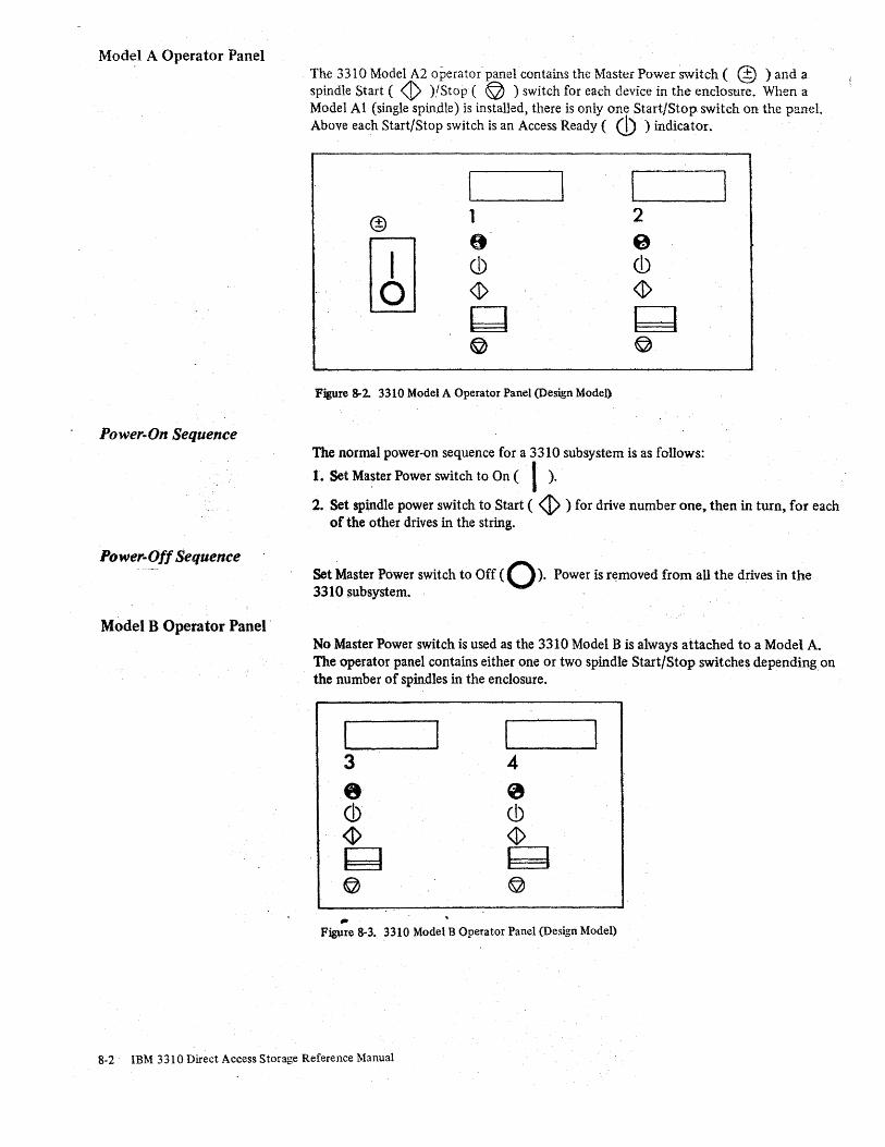
Model A Operator Panel
Power-On Sequence
Power-Off Sequence
Model B Operator Panel'
The 3310 Model A2 operator' panel contains the Master Power Switch ( @ ) and a spindle Start ( <I> )/Stop ( © ) switch for each device in the enclosure. When a Model At (single spindle) is installed, there is only one Start/Stop switch on the panel. Above each Start/Stop switch is an Access Ready ( (J)) indicator. ,
Figure 8-2. 3310 Model A Operator Panel (Design Model)
The normal power-on sequence for a 3310 subsystem is as follows:
1. Set Ma~ter Power switch to On ( I ). 2. Set splndle power switch to Start ( <I> ) for drive number one~ then in turn~ for each
of the other drives in the string.
Set Master Power switch to Ofr ( 0). Power is removed from all the drives in the 3310 subsystem. ' ,
No Master Power switch is used as the 3310 Model B is always attached to a Model A. The operator panel contains either one or two spindle Start/Stop switches depending on the number of spindles in the enclosure .
.. Figure 8-3. 3310 Model B Operator Panel (Design Model)
8-2 IBM 3310 Direct Access Storage Reference Manual

Abbreviations
AGC " Automatic Gain Control CCW· " Channel Command Word CRC " Cyclic Redundancy Check DASDA" Direct Access Storage Device Adapter OS -DataSet DSD - Disk Storage Device ECC - Error Correction Code ECF. - Error Correction Function EREP" Environmental Recording, Editing~ and Printing ERP - Error Recovery Procedure 10< - Identifier Field 1/0- Input/Output n~L .. Initial .Program Load LBN .. Logical ~lock Number PBN -Physical Block Number PSW- Program Status Word RPS .. . Rotational Position Sensing RlW .. Read/\Vrite SLI - Suppress Length Indicator
Abbreviations A-I
IBM 3310 Direct Access Storage Reference IYbnual
Order No. GA26-1660-1
This manual is part of a library that serves as a reference source, for systems analysts. programmers, and operators of IBM systems. .
This form may be used to communicate your views about this publication. They will be sent to ' the author's department for whatever review and action, if any, is deemed appropriate. Comments may be written in your own language; use of English is not required.
IBM may use or distribute any of the information you supply in any way it believes appropriate without incurring any obligation whatever. You may, of course, continue to use the information you supply_
Note: Copies of IB/'r! publications are nat stacked at the location to which ntis jlJrm is addressed. Please direct qny requests for copies of publications, or fiJrassistance in using your IBM system, to your IBM representative or to the IBM 'branch office servin/( your locality. , Possible topics for comment are:
Clarity . Accur.acy Completeness . Organization Coding Retrieval Legibility
If you Wish a reply, give your name and mailing address:
. READER1S COMMENT FORM
Number ofJatest Newsletter associated with this publication: ________________ _
Thank you for your cooperation. No postage ::.tamp necessary if mailed in the U.S.A. (Elsewhere. an IBM "ffirf> or rf>nrf>'f>nt~tivf> will hp. h~nnv to forward your comments.)

, GA26-166D-1
Reader's Comment Form
Fold Please Do Not Staple Fold .............. , ................ ~ ......................................................... "' ..... "' ........ "' ........ "' "' .. "
Business Reply Mail No postage stamp necessary if mailed in the U.S.A.
International Business Machin·!s Corporation Department G26 555 Bailey Avenue San Jose, California 95150
First Class . Permit 2078 San Jose California
IX [.
-ClIoo W
..................................................................................................................... r .~: l'~~ . ?/!!J~ Fold Please 00 Not Staple
------- -----.. -'----. ---- - - ---------_._,..-International Business Machines Corporation Data Processing Division 1133 Westchester Avenue, White Plains, N.Y. 10604
IBM World Trade Americas/Far East Corporation Tow!') of Mount Pleasant, Route 9, North Tarrytown, N.Y., U.S.A. 10591
IBM World Trade Europe/Middle East/ Africa Corporation 360 Hamilton Avenue, White Plains, N.Y., U.S.A. 10601
Fold
t ~~:' ::3·!.i
·:r~~ I c.: ... · '. en:
»J .li~~,¥j t· Ct, »
I\J
I
f
C(l -0> 0> '? -"