Embed Size (px)
Citation preview

I Ill11 11111111111111111111111111 11111 11111 11111 11111 Ill11 1llll111111111 Ill1 United States Patent [I91
US005301 596A [ i i ] Patent Number: 5,301,596
Huey, Jr. [45] Date of Patent: Apr. 12, 1994
[54] SHUTTLE PLATE BRAIDING MACHINE
[75] Inventor: Cecil 0. Huey, Jr., Clemson, S.C.
[73] Assignee: Clemson University, Clemson, S.C.
[21] Appl. No.: 862,779
[22] Filed: Apr. 3, 1992
[51] Int. C l . 5 ................................................ DO4C 3/04 [52] U.S. C1. .......................................................... 87/8 [58] Field of Search ......................... 87/5, 7, 8, 17, 28,
87/30, 31, 33, 38, 39, 40, 46, 50, 51, 55, 56, 57
[561 References Cited U.S. PATENT DOCUMENTS
952,950 3/1910 3,426.804 2/1969 4,312261 VI982 4,615,256 10/1986 4,621,560 1 VI986 4,719,837 ]/I988 4,800,796 ]/I989 4,881,444 11/1989 4,885,973 12/1989 4,898,067 2/1990 4,916,997 4/1990 4,922,798 5/1990 4,936,186 6/1990 4,984,502 ]/I991 5,067,525 11/1991
Schmidt .................................. 87/38 Bluck . Florentine . Fukuta et al. . Brown et ai. . McConnell et al. . Vendramini . Krauland . Spain .................................... 87/5 X Ashton et al. ...................... 87/33 X Spain . Ivsan et a]. ........................... 87/5 X Sekido et al. . Spain et al. ........................... 87/5 X Tsuzuki et al. ..................... 87/33 X
FOREIGN PATENT DOCUMENTS 2301696 7/1973 Fed. Rep. of Germany .......... 87/33
OTHER PUBLICATIONS “AYPEX: A New Method of Composite Reinforce- ment Braiding” by Richard D. Weiler. NASA Confer-
ence Publication 2420. Proceedings of a working-group meeting held at the David Taylor Naval Ship Research and Development Center, Annapolis, Md., Nov. 5-7, 1985. “Magnaweave Process-From Fundamentals to Appli- cations’’ by Robert A. Florentine. Presented at the Fiber Society Symposium on Fiber Reinforced Com- posites, Charlotte, N.C., Dec. 2-3, 1981. “A New 3D Braid For Integrated Parts Manufacture and Improved Delamination Resistance-The 2-Step Process” by Peter Popper and Ronald McConnell. 32nd International SAMPE Symposium, Apr. 6-9, 1987. “Analysis and Automation of Two-step Braiding” by Guang-Wu Du, Peter Popper and Tsu-Wei Chou, Fiber Tex ’88 Conference, Greenville, S.C., Sep. 13-15, 1988.
Primary Examiner-Joseph J. Hail, 111 Attorney, Agent, or Firm-Dority & Manning
1571 ABSTRACT A method and apparatus for moving yarn in a selected pattern to form a braided article. The apparatus in- cludes a segmented grid of stationary support elements and a plurality of shuttles configured to carry yarn. The shuttles are supported for movement on the grid assem- bly and each shuttle includes a retractable plunger for engaging a reciprocating shuttle plate that moves below the grid assembly. Such engagement at selected times causes the shuttles to move about the grid assembly in a selected pattern to form a braided article of a particular geometry.
21 Claims, 8 Drawing Sheets
!25 20
https://ntrs.nasa.gov/search.jsp?R=20080003999 2020-04-22T12:43:11+00:00Z

U.S. Patent Apr. 12, 1994 Sheet 1 of 8 5,301,596

US. Patent
30
i
65 -I
Apr. 12, 1994 Sheet 2 of 8
1 100
1 I t I
5,301,596
I I 1 ~ 9 0 1
55b
5
U.S. Patent Apr. 12, 1994 Sheet 3 of 8 5,301,596
70
120 J
FIG. 3

U.S. Patent Apr. 12, 1994
125 J
Sheet 4 of 8
20
5,301,596
130
FIG. 4

U.S. Patent Apr. 12, 1994 Sheet 5 of 8 5,301,596
FIG. 5

US. Patent Apr. 12, 1994 Sheet 6 of 8 5,30 1,596
FIG. 6

US, Patent Apr. 12, 1994 ,
95
I45
,a,
Sheet 7 of 8
i- 156
5,301,596
v 5 0
f$45
\ 4 FIG. 8 FIG. 7

U.S. Patent Apr. 12, 1994 Sheet 8 of 8 5,301,596
FIG. 9 A
55 b
55a 55 b
FIG. 9B
n -40 n -40 A A
55 b
55a
2o FIG. 9 C 15

5,301,596 1 2
The means for selectively engaging the shuttle plate may include a solenoid actuated retractable plunger, and the shuttle plate may define a plurality of holes
This invention was made with Government support therein for receipt of the retractable plunger when it is under Contract No. NCC1-128 awarded by NASA. 5 actuated. In addition, the means for driving the shuttle The Government has certain rights in this invention. plate causes the shuttle plate to reciprocate in a horizon-
tal plane along two orthogonal axes, the shuttle plate BACKGROUND OF THE INVENTION moving in only a single direction at any particular time.
The present invention relates generally to a method The objects of the present invention are also accom- and apparatus for moving yam in a selected pattern, and 10 plished by the method of moving yarn in a selected more particularly to a method and apparatus for mov- pattern to form a braided article comprising the steps of, ing yarn in a selected pattern to generate braided arti- providing a grid assembly of stationary support ele- cles of various configurations. The present invention ments, supporting a plurality of yarn carrying shuttles improves upon weaving techniques currently known with retractable plungers on the grid assembly, recipro- for generating complex forms such as the pre-form 15 cating a movable shuttle plate below the grid assembly structures used in producing composite materials. Cur- in a plane along two orthogonal axes, and selectively rently known three dimensional braiding devices are and independently actuating the plungers to engage the either limited in flexibility with respect to the braiding shuttle plate as it reciprocates to cause the shuttles to patterns obtainable, o r obtain flexibility at the expense move in a selected pattern along the grid assembly to of complexity of the device. A number of known braid- 20 thereby form a braided article of predetermined geome- ing device produce braid patterns that are intrinsic to try. the particular device being used, and d o not allow for The apparatus and method generate braid patterns by various braiding patterns on a single device. Other moving individual yarn ends, selectively and indepen- known braiding methods allow flexibility in braiding dently, from point to point above the grid assembly. patterns, but are extremely complex in operation, such 25 Independent control of the motion of each shuttle is complexity making practical implementation and opera- achieved through computer control, permitting shuttle tion difficult and expensive. movements to be accomplished as needed without re-
quiring physical adjustments to the basic machine. This indeDendent control Dermits the generation of any SUMMARY O F THE INVENTION
SHU'ITLE PLATE BRAIDING MACHINE
The present invention recognizes and addresses the 30 three-dimensional braii pattern that ;an be formed by a combination of yarn movemenJs. The present invention enables enhanced control of fiber orientation within braided articles, facilitating optimum design of parts that must be subjected to complex loads or that have
Other objects, features and aspects of the present
foregoing disadvantages, and others of prior art con- structions and methods.
Accordingly, it is an object of the present invention to provide an improved apparatus for moving yarn in a selected pattern. 35 complex shapes.
It is another object of the present invention to pro- vide an improved method of moving yarn in a selected invention are discussed in greater detail below.
BRIEF DESCRIPTION O F T H E DRAWINGS pattern.
It is a further object of the present invention to pro- vide a method and apparatus capable of producing a 40 A full and enabling disclosure of the present inven- variety of structural shapes of braided articles. tion, including the best mode thereof, to one of ordinary
It is another object of the present invention to pro- skill in the art, is set forth more particularly in the re- vide a braiding method and apparatus that utilizes a mainder of the specification, including reference to the minimal number of actively controlled devices. accompanying figures, in which:
FIG. 1 is a perspective view of an apparatus in accor- vide a method and apparatus for braiding wherein the dance with the present invention; actively controlled actions are mechanically uncompli- FIG. 2 is a sectional view of FIG. 1 taken along lines
These and other objects and features of the present FIG. 3 is a sectional view of FIG. 2 taken along lines invention are achieved by providing an apparatus for 50 3-3; moving yarn in a selected pattern to form a braided FIG. 4 is a sectional view of FIG. 2 taken along lines article, the apparatus including a grid assembly of sta- 4-4 tionary support elements and a plurality of shuttles FIG. 5 is a sectional view of FIG. 2 taken along lines configured to carry yarn, the shuttles being supported 5-5; for movement on the grid assembly, and each shuttle 55 FIG. 6 is a sectional view of FIG. 2 taken along lines including means for selectively engaging a movable 6-6; shuttle plate. The apparatus further includes a movable FIG. 7 is a perspective view partially in section of an shuttle plate located below the grid assembly and embodiment of a shuttle in accordance with the present adapted to impart motion to the shuttles when the shut- invention; tles engage the shuttle plate. FIG. 8 is a perspective view of another embodiment
The apparatus also includes means for driving the of a shuttle in accordance with the present invention; shuttle plate, and means for controlling the selective and engagement means so as to cause engagement between FIGS. 9A-9D are a sequential schematic representa- the selective engagement means and the shuttle plate to tive of the shuttle plate operation illustrating movement cause the shuttles to move in a controlled pattern, 65 of a single shuttle along one axis. whereby when said shuttles carry yarn and are moved Repeat use of reference characters in the present in a controlled pattern, a braided article of predeter- specification and drawings is intended to represent same mined geometry will be formed. or analogous features or elements of the invention.
It is a further object of the present invention to pro- 45
cated. 2-2;
60

5.301.596
DETAILED DESCRIPTION O F PREFERRED EMBODIMENTS
It is to be understood by one of ordinary skill in the art that the present discussion is a description of exem- 5 plary embodiments only, and is not intended as limiting the broader aspects of the present invention, which broader aspects are embodied in the exemplary con- struction.
accordance with the present invention is illustrated generally at 10. The apparatus includes a stationary support base 15, a movable shuttle plate 20 located above the base 15, and a stationary grid assembly 25. Grid assembly 25 includes a plurality of stationary sup- 15 port elements 30 oriented so as to form movement chan- nels 31 between any given pair of stationary support elements 30. In a preferred embodiment, each stationary support element 30 is square and the grid assembly 25 is
While the apparatus of the present invention is illus- trated with a grid assembly comprising a 5X 5 matrix of stationary support elements 30, it should be understood by one skilled in the art that this is for illustrative pur- poses only. It is within the scope of the present inven- 25 tion to have a grid of any desired size with any number of stationary support elements 30, depending on the size and shape of the article to be produced. It is also within the scope of the present invention to utilize a plurality of apparatus 10 located proximate one another to pro- 30 duce an article of desired size or shape.
The apparatus in accordance with the present inven- tion also includes shuttles 40 configured to carry yarn. Shuttles 40 are supported for movement on grid assem- bly 25 along the movement channels 31 formed between 35 the individual stationary support elements 30. While three shuttles 40 are illustrated in FIG. 1, it should be understood that the number of shuttles 40 will vary depending on the number of braiding yarns being uti- lized to form the braided article. Therefore, any number 40 of shuttles 40 can be utilized on a particular grid assem- bly to form a particular product. The final braided arti- cle (not illustrated) is formed above the shuttles where yarn 150 extends.
be supported for movement with respect to base 15 and grid assembly 25 by rack and pinion mechanisms 45. Rack portions 45a are attached to base 15 and pinion portions 456 are operatively connected to shuttle plate 20. These rack and pinion mechanisms 45 allow move- 50 ment of the shuttle plate 20 back and forth in the direc- tion indicated by arrow A. Movement of shuttle plate 20 back and forth in the direction indicated by arrow B is provided by guide blocks 55 which ride on guide rods 50. Guide blocks 55 are operatively connected to shuttle 55 plate 20, and guide blocks 55 are fixed against move- ment in the direction of arrow B. While a rack and pinion and guide block mechanism is illustrated for supporting shuttle plate 20, any mechanism that main- tains shuttle plate 20 in alignment with grid assembly 25 60 could be utilized. Use of the rack and pinion and guide block mechanism insures that shuttle plate 20 recipro- cates smoothly without binding when in operation.
Means for driving shuttle plate 20 are also provided. In a preferred embodiment, the means for driving shut- 65 tle plate 20 includes a first pair of fluid actuated cylin- ders 55a and 55b and a second pair of fluid actuated cylinders 56a and 566. These fluid actuated cylinders
Referring to FIG. 1, an apparatus for moving yam in 10
surrounded by a frame 35. 20
As illustrated in FIG. 1, movable shuttle plate 20 may 45
4 cooperate to provide reciprocating movement to the shuttle plate 20 in a horizontal plane along two orthogo- nal axes indicated by lines A and B, the shuttle plate moving only in a single direction at any particular time. As is apparent, when cylinder 55a is actuated, shuttle plate 20 will be moved in the direction of arrow A toward cylinder 556. When 556 is actuated, shuttle plate 20 will be moved back in the direction of arrow A toward cylinder 55~7. Cylinders 56u and 566 operate in a similar manner in the direction of arrow B. Actuation of all fluid actuated cylinders may be controlled by a cen- tral processing unit 60. In another embodiment, the shuttle plate 20 may be caused to reciprocate at a given frequency without control by the central processing unit 60.
As illustrated in FIG. 1, central processing unit 60 also controls the actuation of yarn carrying shuttles. Central processing unit 60 can be programmed to selec- tively actuate shuttles 40 to engage and disengage shut- tle plate 20 as it reciprocates. Such selected actuation will cause shuttles 40 to move about grid assembly 25 in a selected pattern to generate the desired braided arti- cle. The pattern of movement of the shuttles is specific to the pattern programmed in the central processing unit 60.
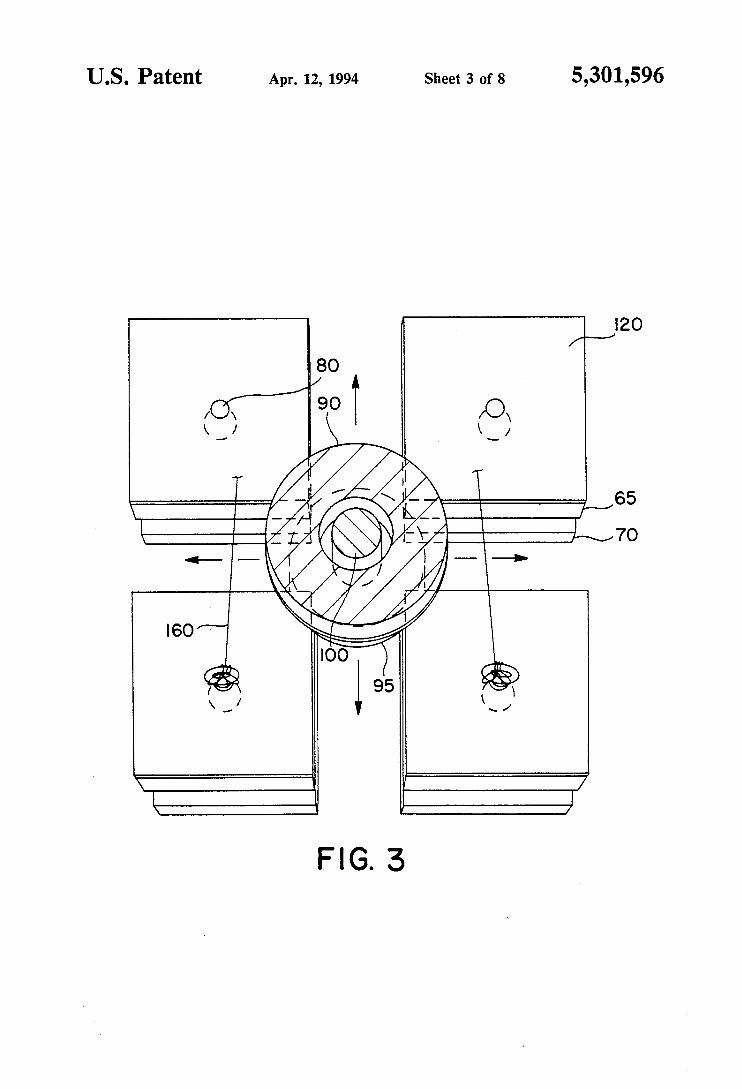
Referring to FIG. 2, stationary support elements 30 that make up the grid assembly 25 will be described in more detail. Each stationary support element 30 in- cludes an upper support element plate 65 with an upper surface 66 and a lower surface 67. Each stationary sup- port element 30 also includes an intermediate support element plate 70 with an upper surface 71 and a lower surface 72. Further, each stationary support element 30 includes a scalloped or contoured lower support ele- ment plate 75 with an upper surface 76 and a lower surface 77. Lower support element plate 75 and inter- mediate support element plate 70 may be unitary or integral.
Each stationary support element 30 is connected to base plate 15 through support shaft 80. As illustrated in FIG. 2, upper support element plate 65 is spaced apart along the axis of support shaft 80 from intermediate support element plate 70 for receipt therebetween of a portion of a yarn carrying shuttle 40. Shuttle plate 20 includes an upper surface 21 and a lower surface 22. Lower surface 22 is slidingly supported on friction re- ducing spacers 85 on base plate 15. This allows shuttle plate 20 to reciprocate with respect to base plate 15 and grid assembly 25.
Referring to FIGS. 1 and 2, each yarn carrying shut- tle 40 includes a base 90 connected by a connecting portion 96 to a guide portion 95 that is spaced from and extends below base portion 90. Each shuttle 40 also includes a solenoid actuated plunger 100 that extends below base 90 and guide portion 95. Plunger 100 in- cludes catch button portion 105 integral therewith at its lower end. Each shuttle 40 also includes onboard con- trol circuitry 110 (FIG. 7) which cooperates with cen- tral processing unit 60 (FIG. 1) to selectively control the actuation of solenoid plunger 100 as will be dis- cussed below. A lower surface of base 90 of shuttle 40 includes a conductive surface 115 that interacts with a conductive surface 120 on the upper support element plate 65 so that power and control signals can be trans- ferred to the onboard control circuit 110 from beneath the grid assembly 25. A complete circuit is formed by elements 95 and 96 contacting portions of support ele- ments 70, 75.

5,301,596 5 6
In one embodiment, continuous power is provided to than once along the A axis before again moving along an activated shuttle to maintain the plunger extended. It the B axis. is also within the scope of the present invention to uti- As best illustrated in FIGS. 2, 4 and 5, when plunger lize a mechanical latching of the plunger with only 100 is retracted, plunger catch button 105 is located in momentary current required to engage the latch, thus 5 substantially the same plane as lower support element reducing the amount of current necessary to operate the plate 75. Plunger catch button 105 is preferably substan- shuttles. In addition, it is within the scope of the present tially circular and matingly engages with contoured invention to transmit power and control signals to shut- Portions 135 Or 136 of lower support element Plate 75. tles 40 by any effective means, such as, for example, This engagement Prevents the shuttle Plate from caw- using wireless transmissions to control shuttles 40. 10 ing unwanted movement of any shuttle 40 because of
AS illustrated in FIGS. 1 and 2, stationary support frictional contact or otherwise when that shuttle's elements 30 are located so as to form movement chan- Plunger 100 retracted. nels 31 therebetween through which yarn carrying As illustrated in FIG. 6, stationary support element
rials onboard control circuit 110 to actuation of 15 and friction reducing spacers 85 are located between
plunger is extended to engage the reciprocating can reciprocate with minimal friction resistance. It
tracted. As best illustrated in FIG. 2, guide portions 95 plate 2o Or
of shuttles extend between upper support element 20 base 15. In addition, it should be appreciated that shuttle plates 65 and intermediate support element plates 70 to plate 2o be suspended for movement above base
plate 15 without actual physical contact such as by use guide shuttles 40 in a stable manner during movement.
Referring to FIG. 7, a shuttle 40 in accordance with maintained in grid assembly 25 by its base 90 riding on 25 one embodiment of the present invention is illustrated in
detail. Shuttle 40 includes a base 90 and a guide portion the upper support element plate upper surface 66 and
shuttles 40 travel when central processing unit 60 sig-
plunger 100 On a particular shuttle. When this occurs,
support shafts 80 are rigidly attached to base PIate
base plate and shuttle plate zo so that shuttle plate 2o
shuttle plate 20 for movement until the plunger is re- should be appreciated that friction reducing spacers 85 be attached to either One Of
As illustrated in FIGS, 2 and 3, each shuttle 40 is Of magnetic levitation Or a bed Of air jets'
guide portion 95 Of 95 connected by a connecting portion 96, Shuttle 40 upper plate 65 and intermediate further includes a 100 and a plunger catch but- port plate 70' Each ton 105 that is adapted to engage shuttle plate holes 125
40 being located between
can be caused to move in directions as indicated by the arrows 3o (illustrated in FIG. 4). Shuttle
chosen position on the grid assembly 25.
also includes a sole-
in a casing 111. Supported atop casing 111 is a yarn bobbin
shuttle plate slots 130. In a preferred embodiment, slots 35 40 is illustrated. The shuttle 40 illustrated in FIG. 8 130 are plate 2o for includes a plunger 105, guide portion 95 connected to movement along two perpendicular axes as indicated by and spaced apart from shuttle base 90. In this embodi- arrows A and B in FIG. 1. Received through slots 130 ment, shuttle base 90 incorporates solenoid 91 and on- are stationary support element support shafts So. Slots board control circuit 110 therein. Supported on shuttle
in so as to be capab1e Of being moved to noid 91 and an onboard control circuit 110 maintained
As illustrated in FIG. 4, shuttle plate 20 includes a 140 supporting a bobbin of yarn 145, plurality of plate lt5 and a plurality Of Referring to FIG. 8, another embodiment o f a shuttle
so as to guide
130 allow shuttle plate 20 to reciprocate by allowing 40 base 90 is a bobbin 140 and a yarn bobbin 145. support shafts 80 to move therein. In a Preferred em- Braiding yarn 150 is illustrated extending from yarn
approximately equal to one-half the distance between a conventional mechanism for maintaining a desired adjacent support members 80. The size of each hole 125 tension in yarn 150, irrespective of the position shuttle must be large enough to ~COmmodate Plunger buttons 45 40 is at on grid assembly 25. The conventional mecha- 105. nism for maintaining a desired tension in yarn 150 may
In operation, shuttle Plate 20 reciprocates below grid include a weight 156 operatively connected to the yarn assembly 25, along one axis at a time (axes A and B in to control the tension of each particular braiding yarn FIG. I) , and does not contact shuttles 40 when shuttle 150 and take up unwanted slack in the yarn during plungers 100 are retracted. When any individual shuttle 50 braiding. Plunger 100 is activated, its Plunger 100 extends down Each onboard control circuit 110 is preferably an to move Plunger catch button 105 into engagement with address-programmable receiverAransmitter circuit. shuttle Plate holes 125 to thereby came shuttle 40 to The selective control of the plunger 100 on each shuttle move in the direction that shuttle Plate 20 is moving is obtained by directing control signals from the central when engaged. The desired movements of the braiding 55 processing unit 60 to specific addresses, with each shut- yarns 150 are obtained by selectively commanding indi- tle 40 representing one address. By this means, each vidual shuttles 40 to engage the shuttle plate as it moves. shuttle can be selectively actuated and deactivated in a When the activated shuttle has moved or indexed with desired sequence to engage the shuttle plate 20 to the shuttle plate 40, it is deactivated so that it is not thereby move the shuttles in the desired pattern. The returned to its previous location when the shuttle plate 60 shuttles may also communicate with the central pro- moves back in the opposite direction. This activation- cessing unit to relay stop signals, to verify instructions, deactivation sequence is continued as controlled by the to report a yarn breakage, or the like. The move com- central processing unit to move the shuttles in the de- mands are transmitted directly to each shuttle and the sired pattern to cause the yarns 150 being carried there- controlled action is an on/off command to activate the above to be braided. Shuttle plate 20 may be actively 65 solenoid on each shuttle. controlled by central processing unit 60 so as to obtain Referring to FIGS. 9A through 9D, operation of the the most efficient movement of the shuttles. For exam- present invention will be described. FIG. 9A illustrates ple, shuttle plate 20 could be caused to reciprocate more two shuttles 40 supported on grid assembly 25 above
bodiment, the length of each 1% o f t h e L-shaped slot is bobbin 145 to tension control device 155 which includes
7 5,301,
shuttle plate 20. Both shuttles have their plungers 100 in the retracted position. Referring to FIG. 9B, the posi- tion of the right side shuttle 40 is illustrated where cen- tral processing unit 60 has signalled onboard control circuit 110 on shuttle 40 to cause plunger 100 to be 5 actuated. When plunger 100 is actuated, it extends plunger button 105 down into shuttle plate hole 125 for engagement therewith. Referring to FIG. 9C, fluid actuated cylinder 550 moves shuttle plate 125 toward the right in FIG. 9C. Since plunger button 105 is re- 10 ceived in shuttle plate hole 125, shuttle 40 will be
,596 8
a plurality of shuttles configured to carry yarn, said shuttles being supported for movement on said grid assembly, each said shuttle including means for selectively engaging a movable shuttle plate;
a unitary movable shuttle plate located below said grid assembly for imparting motion to each of said shuttles, and capable of moving said shuttles through the entire grid when said shuttles intermit- tently engage said shuttle plate;
means for driving said shuttle plate; and means for controlling said selective engagement
moved to the right the same distance that the shuttle means so as to cause engagement between said plate is moved by fluid actuated cylinder 557. As illus- selective engagement means and said shuttle plate trated in FIG. 9D, the central processing unit then to cause said shuttles to move in a controlled pat- causes plunger 100 to be retracted prior to the shuttle 15 tern whereby when said shuttles carry yarn and are plate 20 reciprocating back in the left direction in FIG. moved in said controlled pattern, a braided article 9D. While FIGS. 9A through D only illustrate move- of predetermined geometry will be formed. ment of one shuttle 40 and in a single direction, it should 2. An apparatus as set forth in claim 1 above, wherein be readily appreciated that selective actuation of plung- each said shuttle includes a yarn bobbin thereon. ers 100 for a number of shuttles will cause selective 20 3. An apparatus as set forth in claim 2 above, wherein engagement with the shuttle plate 20, which is recipro- each said bobbin includes a yam tension control device cating in a horizontal plane about the orthogonal axes, thereon. the shuttle plate moving only in a single direction at any 4. An apparatus as set forth in claim 1 above, wherein particular time, to therefore move any particular shuttle each said stationary support element includes an upper 40 by a series of steps to any desired location on grid 25 support element plate, an intermediate support element assembly 25. Therefore, the central processing unit can plate spaced below said upper support element plate, be programmed to cause any number of shuttles 40 to and a lower support element plate adjacent said inter- move in any predetermined pattern desired by a series mediate support element plate. of address specific on/off commands to the shuttles so 5. An apparatus as set forth in claim 4 above, wherein as to produce a desired braided article. Since the central 30 said intermediate support element plate and said lower processing unit may also control the movement of shut- support element plate are unitary. tle plate 20, the central processing unit can be pro- 6. An apparatus as set forth in claim 1 above, wherein grammed to actuate the desired plungers when the shut- said means for driving include fluid actuated cylinders tle plate holes are in the proper location for the desired in operative communication with said shuttle plate. action. Of course, any method of insuring the plunger 35 7. An apparatus for moving yarn in a selected pattern buttons engage the shuttle plate holes properly could be to form a braided article, said apparatus comprising: utilized. a grid assembly of stationary support elements;
As illustrated in FIGS. 1, 2 and 3, stationary axial a plurality of shuttles configured to carry yarn, said non-braiding yarns 160 can be located at desired posi- shuttles being supported for movement on said grid tions on grid assembly 25 to introduce axial yarns into 40 assembly, each said shuttle including a retractable the braided article without affecting either the control plunger for selectively engaging a movable shuttle or mechanical operation of the apparatus. In a preferred plate; embodiment, support members 80 may be hollow to a movable shuttle plate located below said grid as- receive axial non-braided yarns from beneath base 15 sembly and adapted to impart motion to said shut- from a spool or the like. In addition, any number of yarn 45 tles when said shuttles engage said shuttle plate; carrying shuttles 40 can be utilized and any type of yarn means for driving said shuttle plate; and that can be braided can be utilized. Further, use of the means for controlling said retractable plunger so as to words above and below in the present specification are cause selective engagement between said plunger intended to express relative relationships of the ele- and said shuttle plate to cause said shuttles to move ments within the apparatus. It should be apparent that 50 in a controlled pattern whereby when said shuttles the entire apparatus could be inverted or operated on its carry yarn and are moved in said controlled pat- side, in which case an element described as above an- tern, a braided article of predetermined geometry other would then be below it. will be formed.
These and other modifications and variations to the 8. An apparatus as set forth in claim 7 above, wherein present invention may be practiced by those of ordinary 55 said plunger is solenoid actuated. skill in the art, without departing from the spirit and 9. An apparatus as set forth in claim 7 above, wherein scope of the present invention, which is more particu- said movable shuttle plate defines a plurality of holes lady set forth in the appended claims. In addition, it therein for receipt of said retractable plunger when said should be understood that aspects of the various em- plunger is selectively actuated. bodiments may be interchanged both in whole or in 60 10. An apparatus as set forth in claim 9 above, part. Furthermore, those of ordinary skill in the art will wherein each said yarn carrying shuttle includes a base appreciate that the foregoing description is by way of portion and a guide portion, said guide portion being example only, and is not intended to be limitative of the interconnected with said base portion by an intercon- invention so further described in such appended claims. necting portion, a lower surface of said base portion
What is claimed is: 65 being spaced from an upper surface of said guide por- 1. An apparatus for moving yarn in a selected pattern tion a distance slightly larger than the height of said
to form a braided article, said apparatus comprising: upper support plate element, said guide portion being a grid assembly of stationary support elements; partially received between said upper support element
5,301,596 9 10
plate and said intermediate support element plate for guided movement about said grid assembly.
11. An apparatus for moving yam in a selected pat- tern to form a braided article, said apparatus compris- ing: 5 able shuttle plate:
a plurality of shuttles configured to carry yarn, said shuttles being supported for guided movement on said grid assembly, each said shuttle including a retractable plunger for selectively engaging a mov-
a movable shuttle plate located between said grid assembly and said stationary base and adapted to impart motion to said shuttles when said retract- able plungers engage said shuttle plate, said shuttle plate defining a plurality of slots for receipt of said support members therethrough, said slots being configured to guide said shuttle plate in a plane along two orthogonal axes, said shuttle plate fur- ther defining a plurality of holes therein for en-
plungers are actuated to obtain the desired move- ment of said shuttles for the selected pattern;
means for driving said shuttle plate in reciprocating motion in a plane along two orthogonal axes, the shuttle plate moving only in a single direction at any particular time; and
means for controlling said retractable plunger so as to cause selective engagement between each said plunger and one said shuttle plate hole to cause said shuttle to move in a controlled pattern whereby when yarn is being carried on said shuttles and when said shuttles are moved in said controlled pattern, a braided article of predetermined geome- try will be formed.
a grid assembly of stationary support elements; a plurality of shuttles configured to carry yarn, said
shuttles being supported for movement on said grid assembly, each said shuttle including means for selectively engaging a movable shuttle plate;
a movable shuttle plate located below said grid as- sembly and adapted to impart motion to said shut- tles when said shuttles engage said shuttle plate;
means for driving said shuttle plate to reciprocate in
shuttle plate moving only in a single direction at any particular time; and
for controlling said selective engagement means so as to cause engagement between said selective engagement means and said shuttle plate to cause said shuttles to move in a controlled pat- tern whereby when said shuttles carry yam and are moved in said controlled pattern, a braided article of predetermined geometry will be formed.
12. An apparatus for moving yarn in a selected pat- tern to form a braided article, said apparatus compris- ing:
a grid assembly of stationary support elements
10
a horizontal plane along two orthogonal axes, the 15 gagement with said retractable plungers when said
20
25
wherein each said stationary support in- 30 15. An apparatus as set forth in claim 14 above, wherein each said shuttle includes a yarn bobbin
16. An apparatus as set forth in claim 14 above, wherein each said stationary support element includes
an upper plate, an interme-
upper support plate, and a lower support element plate adjacent said intermediate support
diate support element plate spaced below said thereon.
element plate; 35 an upper support element plate, an intermediate support a plurality of shuttles configured to carry Yarn, said element plate spaced below said upper support element
shuttles being supported for movement on said grid plate, and a lower support element plate adjacent said assembly, each said shuttle including means for intermediate support element plate. selectively engaging a movable shuttle plate; 17. An apparatus as set forth in claim 16 above,
a control circuit on each said shuttle for controlling 40 wherein each said yarn carrying shuttle includes a base the actuation of the selective engagement means; portion and a guide portion, said guide portion being
a movable shuttle plate located below said grid as- interconnected with said base portion by an intercon- SemblY and adapted to impart motion to said shut- necting portion, a lower surface of said base portion ties when said shuttles engage said shuttle Plate; being spaced from an upper surface of said guide por-
means for driving said shuttle plate; and 45 tion a distance slightly larger than the height of said means for controlling said selective engagement upper support plate element, said guide portion being
means SO as to cause engagement between said partially received between said upper support element selective engagement means and said shuttle Plate plate and said intermediate support element plate for to cause said shuttles to move in a controlled pat- guided movement about said grid assembly. tern whereby when said shuttles carry Yarn and are 50 18. An apparatus as set forth in claim 17 above, moved in said controlled pattern, a braided article wherein each of said plungers includes a button thereon of predetermined geometry will be formed. for engaging said shuttle plate holes, and said lower
13. An apparatus as set forth in claim 12 above, support element plates have semi-circular contours wherein said upper support element plate includes an about their periphery to receive said buttons when said electrically conductive surface thereon and said base 55 plungers are retracted to prevent said shuttles from portion of said shuttle includes an electrically conduc- moving when they are not engaged with the shuttle tive surface thereon adapted to be in operative contact plate. with said upper support element plate conductive sur- 19. A method of moving yarn in a selected pattern to face, whereby power and control signals can be con- form a braided article, the method comprising the steps veyed to the control circuit of each shuttle.
14. An apparatus for moving yarn in a selected pat- providing a grid assembly of stationary support ele- tern to form a braided article, said apparatus compris- ments; ing: supporting a plurality of yarn carrying shuttles with
retractable plungers on said grid assembly; reciprocating a movable shuttle plate below said grid
assembly in a plane along two orthogonal axes; selectively and independently actuating said plungers
to engage said shuttle plate as it reciprocates to
60 of:
a stationary base; a grid assembly of stationary support elements, each 65
said support element including a support member fixedly connecting said support elements to said base;

5,301,596 12
one axial yarn on the grid assembly to be incorporated into the braided article, cause said shuttles to move in a selected pattern
along the grid assembly to thereby form a braided
article of predetermined geometry.
21. The method as set forth in claim 19 above, and further including the step of providing tension control
5 to the yarn carried on the shuttles so that a desired tension will be maintained as the shuttles move across the grid assembly.
20. The method as set forth in claim 19 above, and
further including the step of fixedly attaching at least * * * * *
10
15
20
25
30
35
40
45
50
55
60
65