Embed Size (px)
Citation preview
I11111 lllllll 111 11111 11111 US0057266 11111 1111 11111 11111 15A Ill11 111111111111111 Ill1 United States Patent [191 [113 Patent Number: 5,726,615 Bloom [45] Date of Patent: Mar. 10, 1998
INTEGRATED-MAGNETIC APPARATUS
Inventor: Gordon E. Bloom, 115 Duran Dr.. San Rafael. Calif. 94903
Appl. No.: 217,477
Filed Mar. 24,1994
Int. C1.6 ............................ HOlF 27/02; HOlF 17/06; HOlF 5/00; HOlF 27/24
U.S. C1. ............................ 336183; 336/178; 336/200; 3361212
Field of Search .............................. 336183, 178, 200, 3361212. 192
References Cited
U.S. PATENT DOCUMENTS
5,010,314 4/1991 Estou ...................................... 336/198 5,175,525 12/1992 Smith ........................................ 336/83 5,386,206 111995 Iwatani et al. .......................... 336i200
OTHER PUBLICATIONS
‘Wew Common-mode Choke Structure for Switchmode Power Supplies” by West and Dickstein. Powertechnics Magazine, Nov. 1985, p. 29. “Integrated-Magnetics Design with Flat, Low-profile Cores” by Cuk et. al., CALTEICH Power Electronics Group Publication, 1989, 13 pages. ‘’Planar Magnetics Simplifies Switchmode Power Supply Design and Construction.” by E. Brown, PCIM Magazine. Jul. 1992, pp. 46-52.
Primary Exarniner-Cassandra C. Spyrou Assistant Examiner-Raymond M. Barrera Attorney, Agent, or F i m J a m e s A. Gabala
[571 ABSTRACT
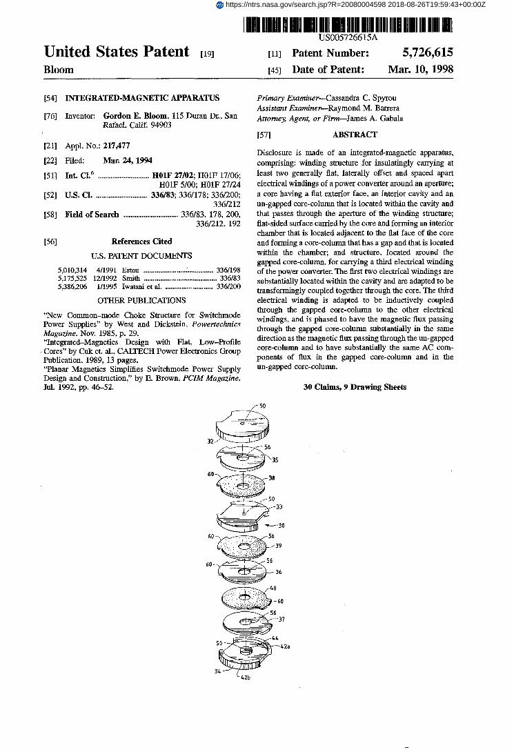
Disclosure is made of an integrated-magnetic apparatus, comprising: winding structure for insulatingly carrying at least two generally flat, laterally offset and spaced apart electrical windings of a power converter around an aperture; a core having a flat exterior face. an interior cavity and an un-gapped are-column that is located within the cavity and that passes through the aperture of the winding structure; flat-sided surface carried by the core and forming an interior chamber that is located adjacent to the flat face of the core and forming a core-column that has a gap and that is located within the chamber; and structure, located around the gapped core-column, for carrying a third electrical winding of the power converter. The first two electrical windings are substantially located within the cavity and are adapted to be transformingly coupled together through the core. The third electrical winding is adapted to be inductively coupled through the gapped core-column to the other electrical windings. and is phased to have the magnetic flux passing through the gapped core-column substantially in the same direction as the magnetic flux passing through the un-gapped core-column and to have substantially the same AC com- ponents of flux in the gapped core-column and in the un-gapped core-column.
30 Claims, 9 Drawing Sheets
f 50
https://ntrs.nasa.gov/search.jsp?R=20080004598 2018-08-26T19:59:43+00:00Z
US. Patent Mar. 10, 1998
FIG. 1A
32
35
60
33
-30
Sheet 1 of 9 5,726,615
FIG. 2A
32 33
FIG. 2B
42a
U.S. Patent Mar. 10, 1998 Sheet 2 of 9 5,726,615
U.S. Patent Mar. 10, 1998 Sheet 3 of 9 5,7264 15
FIG. 5A FIG. 5B
FIG. 6A FIG. 6B
U.S. Patent Mar. 10, 1998 Sheet 4 of 9 5,726,6 15
FIG. 3A
FIG. 78
4 FIG. 8A FIG.88
FIG. 8C
U S . Patent Mar. 10, 1998 Sheet 5 of 9 5,726,6 15
FIG. 9
30f
FIG. 1OA
46t
0.3
FIG. 1OB
Y.
NS inc
lNp
US* Patent Mar. 10, 1998 Sheet 6 of 9
FIG.
5,7264 15
10c
FIG. 11
FIG. 12A 30'f FIG. 128
U.S. Patent Mar. 10,1998 Sheet 7 of 9 5,726,6 15
FIG. 13A \
s
US. Patent Mar. 10, 1998 Sheet 8 of 9 5,726,615
U.S. Patent Mar. 10, 1998 Sheet 9 of 9 5,726,615
FIG. 15A r 66
FIG. 15B ( 64'
L 17
FIG. 17
50
5,726,615 1 2
research, as applied to certain specialized converters, has been reported “Integrated-Magnetics Design with Flat, Low- Profile Cores” by Cuk et. al., CALTECH Power Electronics Group Publication. 1989, 13 pages. However, the applica-
5 tion of planar IM concepts to conventional converter and inverter topologies does not appear to have been explored.
SUMMARY OF THE WVENTION
A general object of the invention is to provide a practical 10 and low-cost design of a planar integrated-magnetic (PIM)
power magnetics for switchmode power-processing circuits. Another object of the invention is to combine the trans-
former and energy-storage components of switchmode con- verter circuits by using low-profile multi-chambered mag-
l5 netic core enclosures and sma l l printed-circuit elements for winding implementations.
Still another object of the invention is to provide a unique construction concept to the implementation of integrated- magnetic power components in simple, low-cost planar
One specific object of the invention is to provide practical PIM structures for high power-processing systems, specs- cally those forms often found in DC power processor
25 networks used in electronic equipment for aerospace and aircraft applications. In accordance with the present invention. an integrated-
magnetic apparatus is disclosed. The apparatus comprises: generally flat electrical insulating means for insulatingly
3o carrying at least two generally flat, laterally offset and spaced apart electrical windings for a power converter around an aperture located therein; a generally flat-faced core having an interior cavity and having an un-gapped core-column that is located within the cavity and that passes
35 through the aperture of the insulating means, wherein the at least two electrical windings are substantially located within the cavity and are adapted to be transformingly coupled together through the core; flat-sided means, carried by one of the flat faces of the core. for forming an interior chamber
4o that is located adjacent to one flat face of the core and for forming a core-column that has a gap and that is located within the chamber; and printed circuit board means, carried within the flat-sided means and around the gapped core- column, for canying at least one electrical winding for the
45 power converter, wherein the at least one electrical winding is substantially located within the annulus, is adapted to be inductively coupled through the gapped core-column to the two generally flat and laterally offset electrical windings and is phased to have the magnetic flux passing through the gapped core-column substantially in the same direction as the magnetic flux passing through the un-gapped core- column and to have substantially the same AC components of flux in the gapped core-column and in the un-gapped core-column.
The planar method used to achieve the PIM construction has been found to be simple and easy to assemble. It also pennits the elimination of a significant amount of magnetic core material when compared to a conventional “discrete” inductor component and transformer assembly of equivalent
60 electrical and magnetic performance capabilities. Moreover, tests of prototype structures have shown that insignificant magnetic interaction exists between the inductive compo- nents of the PIM core structure, p e r m i ~ n g planar consoli- dation of their functions in simple and easy-to-assemble
Core material savings was made possible by using a flat-faced core having a center core “plate” as a common flux
2o formats.
55
65 ferrite core arrangements.
INTEGRATED-MAGNETIC APPARATUS
GOVERNMENT INTEWT
This invention was made with Government support under a contract (SBIR NAS7-1225) awarded by the National Aeronautics and Space Administration (NASA). The Gov- ernment has certain rights in this invention.
TECHNICAL mELD
This invention relates to the general subject of integrated- magnetics and. in particular, to integrated-magnetic appara- tus having a flat or planar form.
BACKGROUND OF THE =ION
The advantages of distributed power are well known: by busing a relatively high voltage to a DC-DC converter near a load, distributed power architecture minimizes distribution losses and provides a stable voltage under variable load conditions. The size of the DC-DC converter restricts or limits how dose it can be to the circuitry it powers. not to mention the overall space penalty it imposes at the system level. Therefore, a major design objective is often to keep the power density as high as possible.
In many applications. converter networks may be required to produce more than one output voltage (or current for a current-controlled application). Also, there are applications where the converter systemmay need to accommodate more than one input source of power, such as an uninterruptible power supply (UPS) application. In addition, all practical converter system applications demand the presence of input filter networks to reduce conducted current emission levels from high-speed converter switching operations to accept- able magnitudes.
The net result is that more power magnetic components, such as an input filter inductor in line with the input power source. more transformer windings (possibly both primares and secondaries) and/or more output filter inductances for the added output lines, are added to a basic converter network.
Increased power density is a mixed blessing. On one hand, it gives the same output or functionality in a smaller package; on the other hand, the converter package has less surface area to dissipate heat. Raising power density also can raise the operating temperature of the converter, which often afFects the reliability of components. Thus, increased power density becomes a counter-productive design objective if oversized heat sinks and noisy power-hungry fans are needed to augment the heat transfer rate of the converter package.
Integrated-magnetics (IM) is one innovative approach that has been exploited in the design of power converters. An overview of integrated-magnetics and power converters is presented in the book “Modern DC-to-DC Switchmode Power Converter Circuits’’ by Severns and Bloom. By “integrated-magnetics” is meant the combining. “lumping” or blending together of magnetic components (e.g., transformers, inductors. etc.) of a switchmode power con- verter into single physical assemblies with little or no compromise in conversion characteristics.
Historically, integrated-magnetic systems have been con- structed using conventional E E or E-I core structures, wound bobbins and hard-wired connections. See “New Common-mode Choke Structure for Switchmode Power Supplies” by West and Dickstein. Powertechnics Muguzine, November 1985, p 29. Flat IM systems andplanar magnetics
5,726,615 3 4
path for both “transformer” and “inductor” magnetic actions. Moreover by proper phasing of the “inductor” winding of the PIM core structure with respect to that of the primary winding. excursions in flux in the common core center plate. due to action of the primary winding, subtract from the DC and AC flux level actions in the inductor winding. The result is that the net flux excursion in the common core center plate is smaller which, in turn, permits the effective cross-sectional area of the center plate to be smaller than the case when the transformer and inductive flux components are additive. In addition. the air gap in one part of the PIM core structure permits very little transformer- related flux to be developed in that part of the PIM core structure, since the reluctance value of the air-gapped core column will be much greater than that posed by the un-gapped core-column of the opposite part of the PIM assembly.
The demonstrated savings in core weight and volume achieved, over equivalent planar “discrete” versions of a transformer and an inductor in a simple forward converter design, has been shown to be on the order of 17%.
The development of the invention has also led to unique extensions of PIM concepts that permit many essential power magnetic functions of a switchmode power- processing network to be included. The potential of the invention is significant, in that new methods for building low-cost power magnetic systems will be available for developing new power converter andor inverter circuits. The commercial use of these concepts is even more significant. since most. if not all, industrial power supply systems use power magnetic components.
I n summary. the inventive concepts disclosed herein have been shown to produce viable PIM devices that can realize significant volume and weight savings, when compared to equivalent “discrete” magnetic devices. These concepts also yield a magnetic system of equivalent electrical and mag- netic performance with no discernible compromke. The closed core structure of the basic embodiment of the inven- tion also provides an effective containment method to reduce magnetic leakage. Also, this core structure provides more exposed surface area for removal of heat developed in the PIM device due to power losses in the planar winding boards. and in the bodies of the core-pieces themselves from magnetic excitation and associated eddy currents in the material of the core-pieces.
Numerous other advantages and features of the present invention will become readily apparent from the following detailed description of the invention. the embodiments described therein. from the claims. and from the accompa- nying drawings.
BRlEF DESCRPIION OF THE DRAWINGS
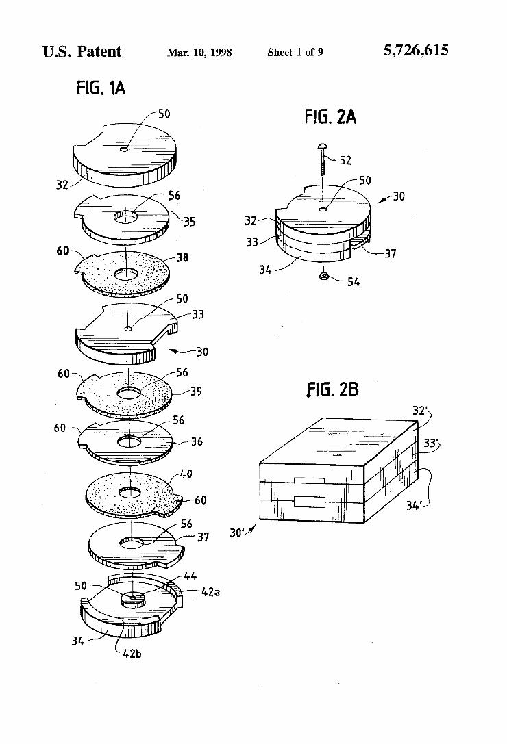
FIG. lAis an exploded assembly diagram of one embodi- ment of the integrated-magnetic (IM) apparatus that is the subject of the present invention;
FIG. 2Ais aperspective view of the assembled integrated- magnetic apparatus of FIG. 1A;
FIG. 2B is a perspective view of another embodiment of an integrated-magnetic apparatus that is the subject of the present invention;
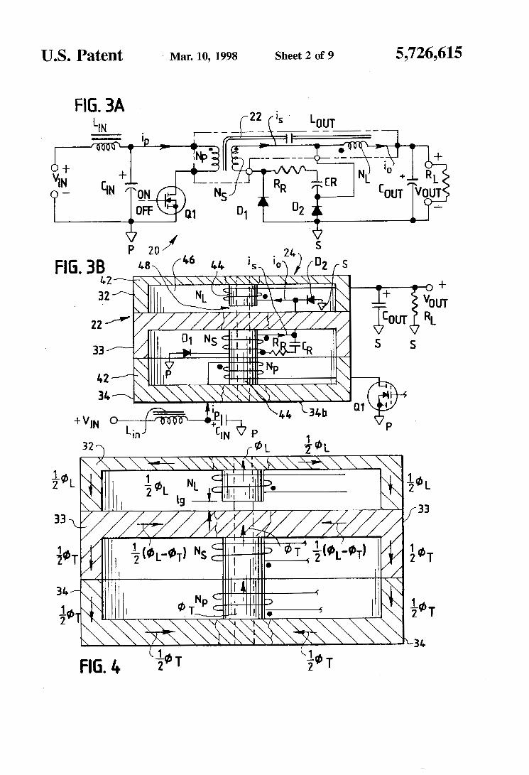
FIG. 3A is an electrical schematic diagram of a forward converter circuit for the integrated-magnetic apparatus of FIG. 2A or FIG. 2B;
FIG. 3B is an electrical schematic diagram of a forward converter circuit in combination with a cross-sectional side
view of the assembled integrated-magnetic apparatus of FIG. 2A or FIG. 2B;
FIG. 4 is an enlarged cross-sectional view of assembled integrated-magnetic apparatus of FIG. 1A illustrating mag-
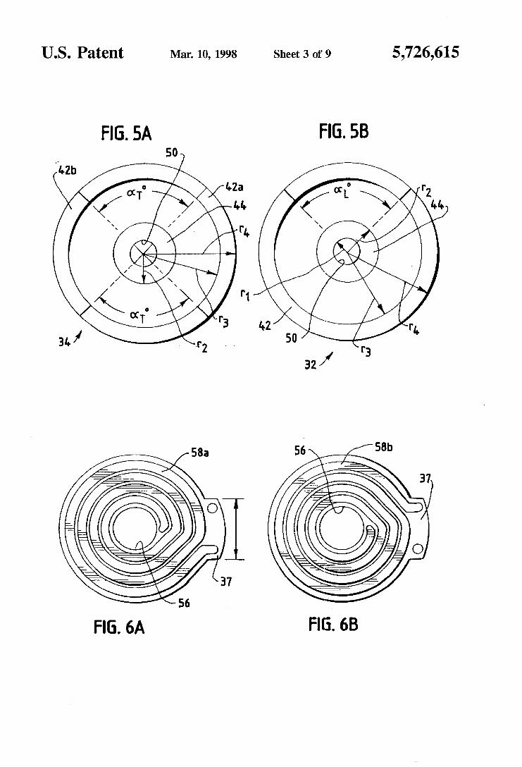
FIGS. 5A and 9 3 are plan views of two core components
FIGS. 6A and 6B are plan views of two sides of a 1o transformer winding component of the integrated-magnetic
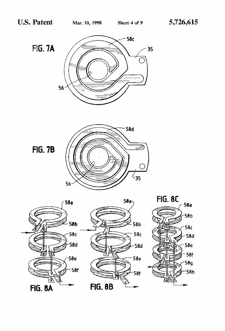
apparatus of FIG. 1A; FIGS. 7A and 7B are plan views of two sides of an
inductive winding component of the integrated-magnetic apparatus of FIG. lA,
FIGS. 8A. 8B and 8C are schematic diagrams of examples of how winding components can be electrically connected together;
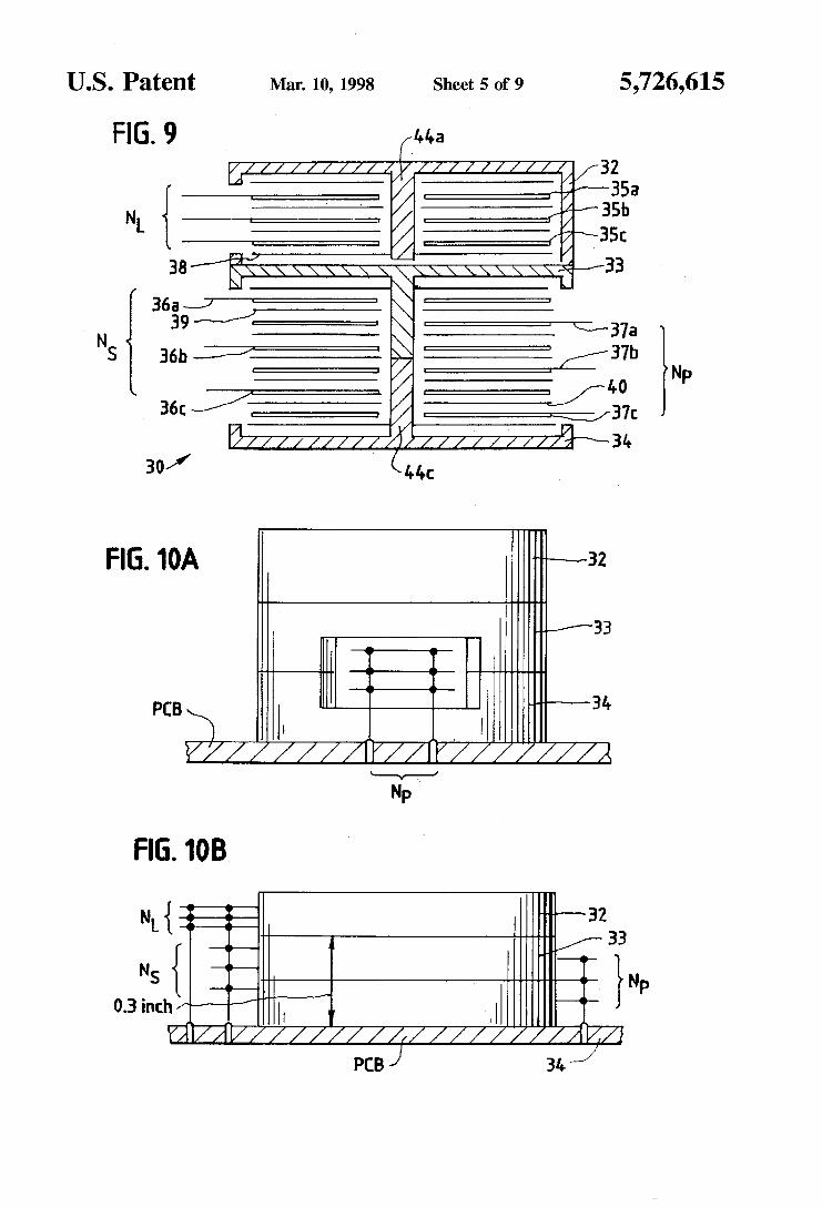
FIG. 9 is a cross-sectional schematic diagram of the assembled integrated-magnetic apparatus of FIG. 2A or FIG.
FIG. 10A is an elevational exterior view of the right side of the integrated-magnetic apparatus of FIG. 9 installed on a circuit board;
FIG. 1OB is an elevational exterior view of the integrated- magnetic assembly of FIG. 9 installed on a circuit board;
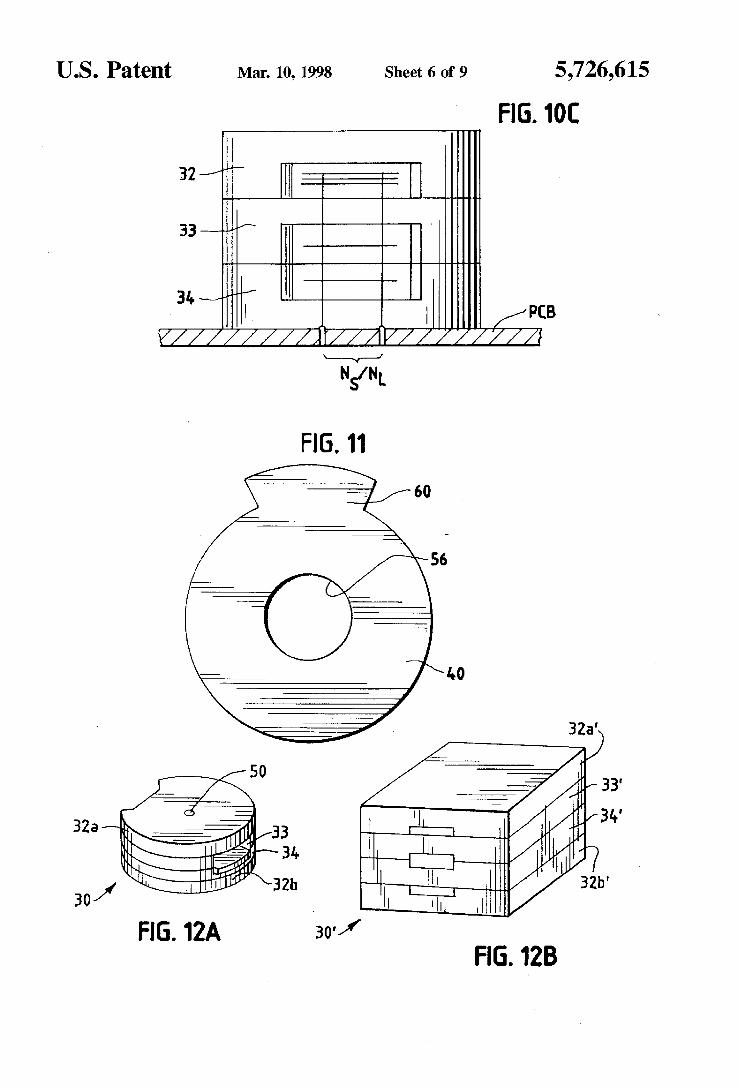
FIG. 1OC is an elevational exterior view of the left side of the integrated-magnetic apparatus of FIG. 9 installed on a circuit board;
FIG. 11 is a plan view of an electrical insulating element; FIGS. 12A and 12B are perspective views of additional
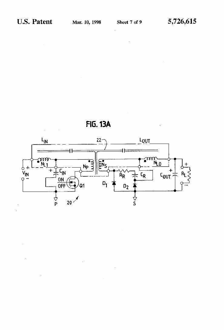
embodiments of the present invention; FIG. 13A is an electrical schematic diagram of a forward
converter circuit and an input filter in combination with a 35 cross-sectional side view of the assembled integrated-
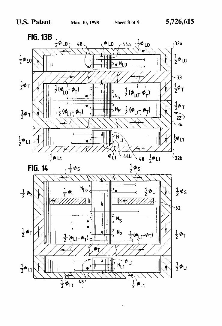
magnetic apparatus of FIG. 12A or FIG. 12B; FIG. 13B is an enlarged cross-sectional view of the
integrated-magnetic apparatus of FIG. 12A or FIG. 12B
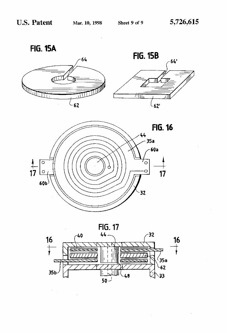
FIG. 14 is an enlarged cross sectional view of another embodiment of a planar integrated-magnetic apparatus;
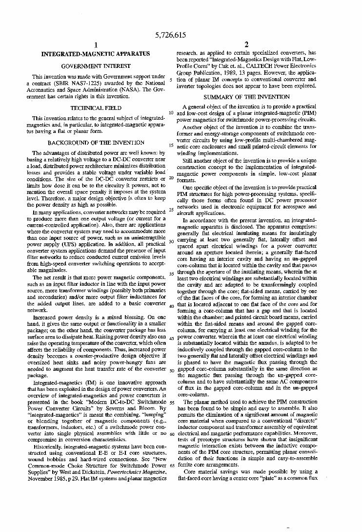
FIGS. 15A and 15B are perspective views of two forms of the reluctance disk shown in FIG. 14;
FIG. 16 is a cross-sectional plan view of the integrated- magnetic apparatus of FIG. 14 as viewed along line 16-16 of FIG. 17; and
FIG. 17 is a partial. cross-sectional view of one end of the integrated-magnetic apparatus of HG. 14.
5 netic flux paths;
of the integrated-magnetic apparatus of FIG. 1A
15
20 2B;
25
30
4o illustrating magnetic flux paths;
45
50
DETAILED DESCRIPTION
While this invention is susceptible of embodiment in many Werent forms. there is shown in the drawings. and
55 will herein be described in detail, several specific embodi- ments of the invention. It should be understood, however. that the present disclosure is to be considered an exempli- fication of the principles of the invention and is not intended to limit the invention to the specific embodiment illustrated.
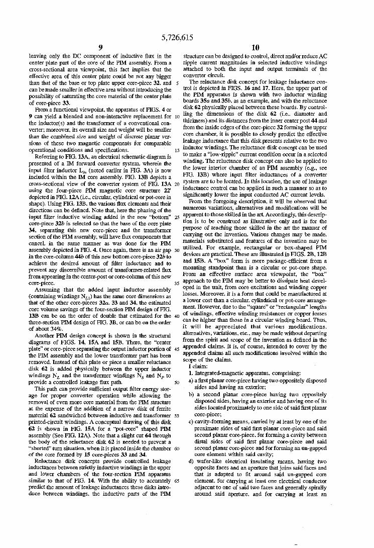
First turning to EIG. 3A. a single-output IM forward converter 20 is depicted with an input filter network, com- prising an inductor L, and a capacitor Gin. A forward converter is a widely used power converter configuration. and one whose operation is well known to those skilled in
65 the art. Nevertheless, it should be understood. in the discus- sions that follow, that the subject matter of the invention is not limited to any one converter topology or the number of
60
5,726,6 15 5
inputs or outputs of a converter. The JM component of the converter 20 comprises a common magnetic core 22 that carries a primary transformer winding Np+ a secondary transformer winding N,, and an output inductor Lo,, winding NL. An input voltage V, is applied to the input filter network Energy stored in the capacitor C, of the input filter is periodically transferred to an output load RL, Lo,, and an output filter capacitor C,,, through the transformer windings in conjunction with a secondary diode D, whenever primary power switch Q, is in an ON-state during a switching cycle. When the switch QI is in an OFF-state, energy for output load power is provided by the output inductor Lo,, through a secondary diode D,. During this same OFF period, mag- netic reset of the transformer part of the IM assembly is accomplished by resonant action of a network formed by a resistor RR. a capacitor CR and the effective inductance of the secondary transformer winding N,. Output voltage or current control is accomplished by regulating circuitry (not shown for simplicity and known to those skilled in the art) which adjusts the ON and OFF times of the power switch Q1 during switching periods of power conversion.
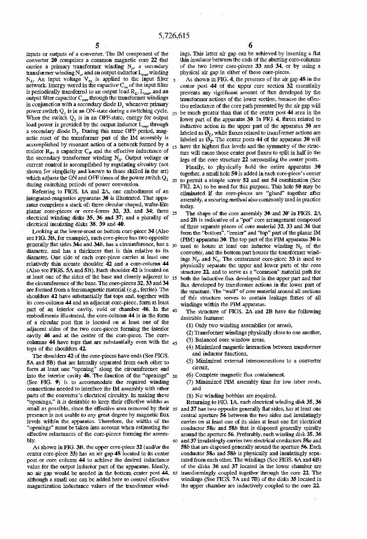
Referring to FIGS. lA and 2A, one embodiment of an integrated-magnetics apparatus 30 is illustrated. That appa- ratus comprises a stack of: three circular shaped, wafer-& planar core-pieces or core-forms 32, 33, and 34. three electrical winding disks 35, 36 and 37; and a plurality of electrical insulating disks 38. 39 and 40.
Looking at the lower-most or bottom core-piece 34 (Also see FIG. 3B, for example), each core-piece has two opposite generally flat sides 34u and 34b, has a circumference. has a diameter, and has a thickness that is thin relative to its diameter. One side of each core-piece carries at least one relatively thin arcuate shoulder 42 and a core-column 44 (Also see FIGS. 5A and 5B). Each shoulder 42 is located on at least one of the sides of the base and closely adjacent to the circumference of the base. The core-pieces 32,33 and 34 are formed from a ferromagnetic material (e.g., ferrite). The shoulders 42 have substantially flat tops and, together with its core-column 44 and an adjacent core-piece, form at least part of an interior cavity, void or chamber 46. In the embodiments illustrated, the core-column 44 is in the form of a circular post that is located on at least one of the adjacent sides of the two core-pieces forming the interior cavity 46 and at the center of the core-piece. The core- columns 44 have tops that are substantially even with the tops of the shoulders 42.
The shoulders 42 of the core-pieces have ends (See FIGS. 5A and 33) that are laterally separated from each other to form at least one “opening” along the circumference and into the interior cavity 46. The function of the “openings” (See FIG. 9) is to accommodate the required winding connections needed to interface the IM assembly with other parts of the converter’s electrical circuitry. In making these “openings,” it is desirable to keep their effective widths as s m a l l as possible, since the effective area removed by their presence is not usable to any great degree by magnetic flux levels within the apparatus. Therefore, the widths of the “openings” must be taken into account when estimating the effective reluctances of the core-pieces forming the assem- bly.
As shown in FIG. 3B. the upper core-piece 32 (and/or the center core-piece 33) has an air gap 48 located in its center post or core column 44 to achieve the desired inductance value for the output inductor part of the apparatus. Ideally, no air gap would be needed in the bottom center post 44, although a s m a l l one can be added here to control effective
6 ings. This latter air gap can be achieved by inserting a flat thin insulator between the ends of the abutting corecolumns of the two lower core-pieces 33 and 34, or by using a physical air gap in either of these core-pieces.
As shown in FTG. 4, the presence of the air gap 48 i n the center post 44 of the upper core section 32 essentially prevents any significant amount of flux developed by the transformer actions of the lower section, because the effec- tive reluctance of the core path presented by the air gap will
10 be much greater than that of the center post 44 area in the lower part of the apparatus 30. In FIG. 4, fluxes related to inductive action in the upper part of the apparatus 30 are labeled as &. while fluxes related to transformer actions are labeled as 0, The center posts 44 of the apparatus 30 will
15 have the highest flux levels and the symmetry of the struc- ture will cause those center post fluxes to split in half in the legs of the core structure 22 surrounding the center posts.
Finally, to physically hold the entire apparatus 30 together, a small hole 50 is added in each core-piece’s center
20 to permit a simple screw 52 and nut 54 combination (See FIG. 2A) to be used for this purpose. This hole 50 may be eliminated if the core-pieces are “glued” together after assembly, a securing method also commonly used in practice
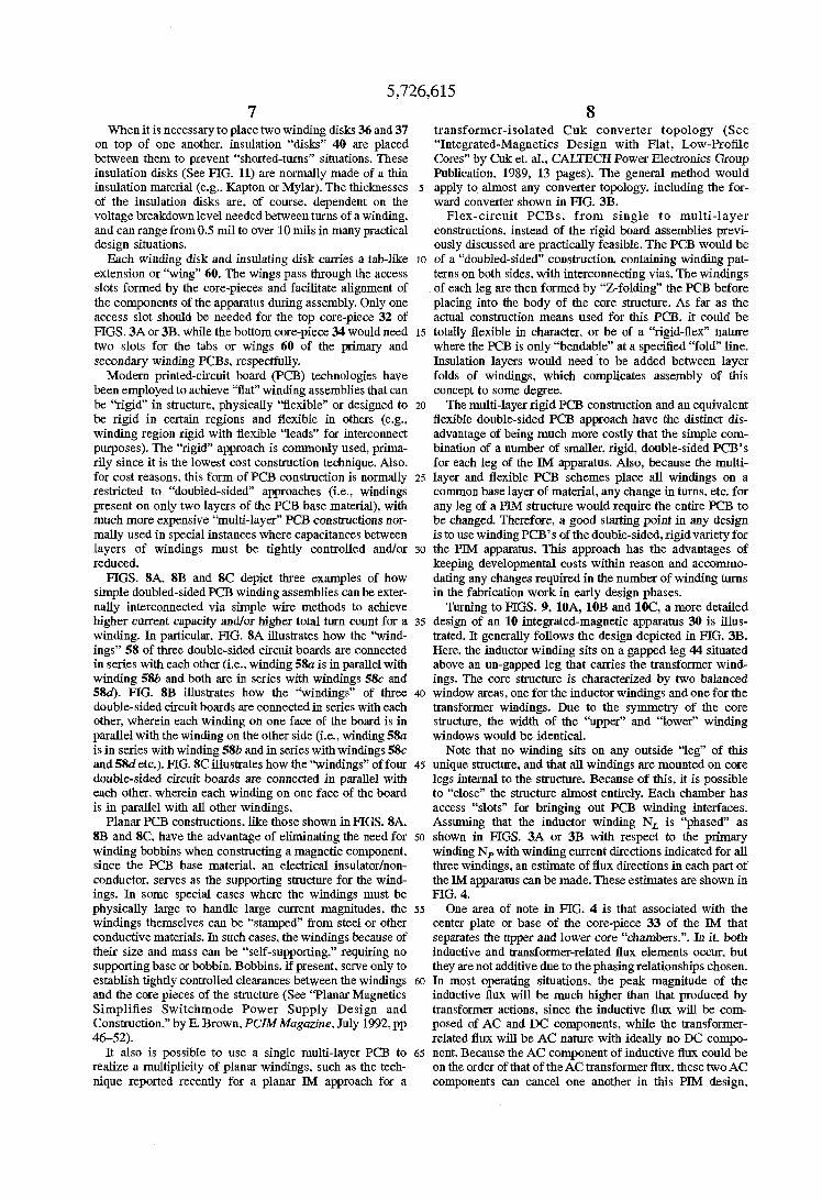
The shape of the core assembly 30 and 30’ in FIGS. 2A and 2B is indicative of a “pot” core arrangement composed of three separate pieces of core material 32,33 and 34 that form the “bottom”, “center” and “top” part of the planar IM (PIM) apparatus 30. The top part of the PIM apparatus 30 is
30 used to house at least one inductor winding NL of the converter, and the bottom part houses the transformer wind- ings Np and N,. The centermost core-piece 33 is used to physically separate the upper and lower parts of the core structure 22. and to serve as a “common” material path for
35 both the inductive flux developed in the upper part and that flux developed by transformer actions in the lower part of the structure. The “wall” of core material around all sections of this structure serves to contain leakage fluxes of all windings within the PIM apparatus.
The structure of FIGS. 2A and 2B have the following desirable features:
(1) Only two winding assemblies (or areas), (2) Transformer windings physically close to one another, (3) Balanced core window areas, (4) Minimized magnetic interaction between transformer
(5) Minimized external interconnections to a converter
(6) Complete magnetic flux containment, (7) Minimized PIM assembly time for low labor costs.
(8) No winding bobbins are required. Returning to FIG. lA. each electrical winding disk 35.36
55 and 37 has two opposite generally flat sides, has at least one central aperture 56 between the two sides and insulatingly carries on at least one of its sides at least one flat electrical conductor 58a and 58b that is disposed generally spirally around the aperture 56. Preferably. each winding disk 35.36
60 and 37 insulatingly carries two electrical conductors 5th and 58b that are disposed generally around the aperture 56. Each conductor 58a and 58b is physically and insulatingly sepa- ratedfrom each other. The windings (See FIGS. 6A and 6B) of the disks 36 and 37 located in the lower chamber are
65 transformingly coupled together through the core 22. The windings (See FIGS. 7A and 7B) of the disks 35 located in
5
today. 25
40
45
and inductor functions,
circuit, 50
and
I .
magneyization inductance values of the transformer wind- the upper chamber are inductively coupled to the core 22.
5,726,6 15 7 8
When it is necessary to place two winding disks 36 and 37 transformer-isolated Cuk converter topology (See on top of one another. insulation “disks” 40 are placed “Integrated-Magnetics Design with Flat, Low-ProNe between them to prevent “shorted-turns” situations. These Cores” by Cuk et. al., CALTECH Power Electronics Group insulation disks (See FIG. 11) are normally made of a thin Publication. 1989, 13 pages). The general method would insulation material (e.g.. Kapton or Mylar). The thicknesses 5 apply to almost any converter topology. including the for- of the insulation disks are. of course, dependent on the ward converter shown in FIG. 3B. voltage breakdown level needed between turns of a winding. Flex-circuit PCBs, from single to multi-layer and can range from 0.5 mil to over 10 m i l s in many practical constructions, instead of the rigid board assemblies previ- design situations. ously discussed are practically feasible. The PCB would be
Each winding disk and insulating disk carries a tab-like IO of a “doubled-sided” construction, containing winding pat- extension or “wing” 60. The wings pass through the access terns on both sides. with interconnecting vias. The windings slots formed by the core-pieces and facilitate alignment of of each leg are then formed by “Z-folding” the PCB before the components of the apparatus during assembly. Only one placing into the body of the core structure. As far as the access slot should be needed for the top core-piece 32 of actual construction means used for this PCB, it could be FIGS. 3A or 3B, while the bottom core-piece 34 would need 15 totally flexible in character, or be of a “rigid-flex’’ nature two slots for the tabs or wings 60 of the primary and where the PCB is only “bendable” at a specified “fold” line. secondary winding PCBs, respectfully. Insulation layers would need to be added between layer
Modern printed-circuit board (PCB) technologies have folds of windings, which complicates assembly of this been employed to achieve “flat” winding assemblies that can concept to some degree. be “rigid” in structure, physically “flexible” or designed to 20 The multi-layer rigid PCB construction and an equivalent be rigid in certain regions and flexible in others (e.g.. flexible double-sided PCB approach have the distinct dis- winding region rigid with flexible “leads” for interconnect advantage of being much more costly that the simple com- purposes). The “rigid” approach is commonly used, prima- bination of a number of smaller, rigid, double-sided PCB’s rily since it is the lowest cost construction technique. Also, for each leg of the IM apparatus. Also, because the multi- for cost reasons, this form of PCB construction is normally 25 layer and flexible PCB schemes place all windings on a restricted to “doubled-sided” approaches (Le., windings common base layer of material, any change in turns, etc. for present on only two layers of the PCB base material), with any leg of a PI34 structure would require the entire PCB to much more expensive ‘’multi-layer” PCB constructions nor- be changed. Therefore, a good starting point in any design mally used in special instances where capacitances between is to use winding PCB’s of the double-sided, rigid variety for layers of windings must be tightly controlled and/or 30 the PIM apparatus. This approach has the advantages of reduced. keeping developmental costs within reason and accommo-
FIGS. SA, 8B and SC depict three examples of how dating any changes required in the number of winding turns simple doubled-sided PCB winding assemblies can be exter- in the fabrication work in early design phases. nally interconnected via simple wire methods to achieve Turning to FIGS. 9, 10A, 1OB and lOC, a more detailed higher current capacity and/or higher total turn count for a 35 design of an 10 integrated-magnetic apparatus 30 is illus- winding. In particular. FIG. SA illustrates how the “wind- trated. It generally follows the design depicted in FIG. 3B. ings” 58 of three double-sided circuit boards are connected Here, the inductor winding sits on a gapped leg 44 situated in series with each other (Le., winding 5&1 is in parallel with above an un-gapped leg that carries the transformer wind- winding 58b and both are in series with windings 5& and ings. The core structure is characterized by two balanced 5 8 4 . FIG. 8B illustrates how the “windings” of three 40 window areas, one for the inductor windings and one for the double-sided circuit boards are connected in series with each transformer windings. Due to the symmetry of the core other. wherein each winding on one face of the board is in structure, the width of the “upper” and “lower” winding parallel with the winding on the other side (Le.. winding 58a windows would be identical. is in series with winding 5Sb and in series with windings 58c Note that no winding sits on any outside “leg” of this and 58d etc.). FIG. SC illustrates how the ‘kindings” of four 45 unique structure, and that all windings are mounted on core double-sided circuit boards are connected in parallel with legs internal to the structure. Because of this. it is possible each other, wherein each winding on one face of the board to “close” the structure almost entirely. Each chamber has is in parallel with all other windings. access “slots” for bringing out PCB winding interfaces.
Planar PCB constructions. like those shown in FIGS. SA, Assuming that the inductor winding NL is “phased” as SB and 8C. have the advantage of eliminating the need for 50 shown in FIGS. 3A or 3B with respect to the primary winding bobbins when constructing a magnetic component. winding Np with winding current directions indicated for all since the PCB base material, an electrical insulator/non- three windings, an estimate of flux directions in each part of conductor. serves as the supporting structure for the wind- the JM apparatus can be made. These estimates are shown in ings. In some special cases where the windings must be FIG. 4. physically large to handle large current magnitudes, the 55 One area of note in FIG. 4 is that associated with the windings themselves can be “stamped” from steel or other center plate or base of the core-piece 33 of the IM that conductive materials. In such cases. the windings because of separates the upper and lower core “chambers.”. In it. both their size and mass can be “self-supporting.” requiring no inductive and transformer-related flux elements occur, but supporting base or bobbin. Bobbins, if present, serve only to they are not additive due to the phasing relationships chosen. establish tightly controlled clearances between the windings 60 In most operating situations, the peak magnitude of the and the core pieces of the structure (See “Planar Magnetics inductive flux will be much higher than that produced by Simplifies Switchmode Power Supply Design and transformer actions, since the inductive flux will be com- Construction.” by E. Brown. PCZMMuguzine. July 1992,pp posed of AC and DC components, while the transformer- 46-52). related flux will be AC nature with ideally no DC compo-
It also is possible to use a single multi-layer PCB to 65 nent. Because the AC component of inductive flux could be realize a multiplicity of planar windings. such as the tech- on the order of that of the AC transformer flux. these two AC nique reported recently for a planar Ih4 approach for a components can cancel one another in this PIM design.
5,726,615 9 10
leaving only the DC component of inductive flux in the center plate part of the core of the PIM assembly. From a cross-sectional area viewpoint, this fact implies that the effective area of this center plate could be not any bigger than that of the base or top plate upper core-piece 32, and 5 can bemade s d e r i n effective withoutintroducingthe possibility of saturating the core materid of the center plate of core-piece 33.
9 can yield a blended and non-interactive replacement for 10 ling the dimensions Of the disk 62
vertai moreover, its size and wa be than the combined size and weight of discrete planar ver-
operational conditions and specifications.
structure can be designed to control, direct and/or reduce AC ripple current magnitudes in selected inductive windings attached to both the input and output terminals of the COnVerter Circuit-
The reluctance disk concept for leakage inductance con- trol is depicted in FIGS. 16 and 17. Here, the Upper part Of
the PIM apparatus is shown with two inductor winding boards 35a and 3% as an example, and with the reluctance
diameter and
from the inside edges of the core-piece 32 forming the upper core chamber, it is possible to closely predict the effective
15 inductor windings. The reluctance disk concept can be used to make a “low-ripple” current condition occur in a selected winding. The reluctance disk concept can also be applied to
From a functional viewpoint, the apparatus of FIGS. 4 or disk 62 Physically placed between these boards. By control-
tKchess) and its distances fromthe innel‘ center post44 and the in&ctor(s) and the transformer of a conventional con-
sions of these two magnetic components for comparable leakage that this diskpresentsrelative to the two
Referring to m ~ . 13A, an diagram is of a IM forward converter system, wherein the
input filter inductor L, (noted e&er in E G . 3A) is now the lower interior chamber Of an see included within the IM core assembly. FIG. 13B depicts a FIG* 13B) where input filter inductances of a converter cross-sectional view of the converter system of FIG. 1 3 ~ 20 system are to be located. In this location* the use o f l e h g e
assembly
using the four-piece pm magnetic structure 22 inductance control can be applied in such a manner so as to depicted in m ~ . 12A (i.e., circular, or pot-core in significantly lower the input conducted AC current levels.
directions can be defined. Note that, here the phasing of the numerous variations, alternatives and modifications will be input filter inductive winding added in the new “bottom” 25 apparent to those skilled in the art. Accordingly, this descrip- core-piece 32b is selected so that the base of the core plate tion is to be as illustrative Only and is for the
purpose of teaching those skilled in the art the manner of 34, separating this new corepiece and the transformer section of the PIM assembly, will have flux components that cancel, in the same Illiinner as was done for the pIM materials substituted and features of the invention may be assembly depicted in FIG. 4. Once again, there is an air gap 30 utilized- For in the core-column 44b ofthis new bottom core-piece 32b to devices are practical. These are illustrated in FIGS. 2B, 12B
the desired mount of filter inductance and to and 15B. A “box” form is more package-efficient from a
in the center-post or core-column of this new From an effective surface area viewpoint, the “box” 35 approach to the PIM may be better to dissipate heat devel-
losses. Moreover, it i s a form that could be manufactured at
merit. However, due to the “square” or “rectangular” lengths of windings, effective winding resistances or copper losses
it will be appreciated that various modifications, alternatives, variations. etc.. may be made without departing from the spirit and scope of the invention as defined in the
shape). Using FIG. 13B, the various flux elements and their From the foregoing description* it will be observed that
Out the invention. various changes my be
Or box-shaped
prevent any discernible amount of transfmer-related flux mounting than is a or Pot-core shape. from core-piece.
Assuming that the added input inductor assembly
that of the other core-pieces 3&, 33 and 34, the estimated
Oped in the unit, from core excitations and winding windings NL1) has the same core dimensions as
core volume savings of the four-section pm design of FIG. 1 3 ~ can be on the order of double that estimated for the
of about 34%. ho the r pIM design concept is shown in the structural
diagrams of m ~ ~ . 14, 1 5 ~ and 1 5 ~ . mere, the “center
a lower cost than a or pot-core mange-
kee-section PJ’M design of FIG. 3B, or can be on the order can be than those in a circular winding board. Thus*
plate” or core-piece separating the output inductor portion of 45 the pm assembly and the lower transformer p& has been
claimS* It is, Of coufse. intended to cover the all such modifications involved within the
removed. Instead of this plate or piece a smaller reluctance disk 62 is added physically between the upper inductor
provide a controlled leakage flux path. This path can provide sufiicient output filter energy stor-
age for proper converter operation while allowing the removal of even more core material from the PIM structure at the expense of the addition of a narrow disk of farite material 62 sandwiched between inductive and transformer 55 printed-circuit windings. A conceptual drawing of this disk 62 is shown in FIG. 15A for a ‘pot-core” shaped PIM assembly (See FIG. 12A). Note that a slight cut 64 through the body of the reluctance disk 62 is needed to prevent a “shorted” turn situation, when it is placed inside the chamber 60 of the core formed by 15 core-pieces 33 and 34,
Reluctance disk concepts provide controlled leakage inductances between strictly inductive windings in the upper and lower chambers of the four-section F’IM apparatus similar to that of FIG. 14. With the ability to accurately 65 predict the amount of leakage inductances these disks intro- duce between windings, the inductive parts of the PIM
scope Of the claims*
windings NL and the transformer windings N, and Np to 1. Integated-magnetic apparatus, 50 a) a first planar core-piece having two oppositely disposed
sides and having an exterior; b) a second planar core-piece having two oppositely
disposed sides, having an exterior and having one of its sides locatedproximately to one side of said first planar COre-PieW
c) cavity-forming means, carried by at least by one of the proximate sides of said first planar core-pime and said second planar core-piece, for forming a cavity between distal sides of said first planar core-piece and said second planar core-piece and for forming an un-gapped core element within said cavity;
d) wafer-like electrical insulating means, having two opposite faces and an aperture that joins said faces and that is adapted to fit around said un-gapped core element, for carrying at least one electrical conductor adjacent to one of said two faces and generally spirally around said aperture. and for carrying at least an
5,726.615 11 12
additional electrical conductor adjacent to the other of said two faces and generally helically around said aperture, said one electrical conductor and said addi- tional electrical conductor forming a plurality of elec- trical windings that are substantially located within said cavity and that are transformingly coupled together in response to the flow of current through said one elec- trical conductor and a transformhg magnetic flux thereformed and passing through said un-gapped core element and said first planar core-piece and said second 1o planar core-piece;
e) insulating means, carried by at least one of said first planar core-piece and said second planar core-piece and said wafer-like electrical insulating means, for electri- cally insulating at least one of said one electrical conductor and said additional electrical conductor from l5
second planar core-piece; said one electrical conducting element is electrically con- f) a third planar core-piece having one side that is located netted to said one
adjacent to one Of said distal Sides of said first planar 2o 5. The integrated-magnetic apparatus of claim 4, wherein core-piece and said second planar core-piece. having an said one electrical conductor is electrically conned& to said opposite side and having an exterior; additional electrical conductor.
g) h o ~ o w - f ~ g means, C a r r i e d at least bY one Of said 6. The integrated-magnetic apparatus of claim 1. further third planar core-piece and said one d i s t a l side Of said including means, c d e d by said gapped core element and first Planar COre-Piece and said second Planar core- 25 said un-gapped core element. for holding together said first Piece, for forming a hollow between the OPPOSite side planar core-piece and said second planar core-piece and said of said third planar core-piece and the other distal side third planar core-piece. of said first Planar COre-Piece and said second Planar 7. The integrated-magnetic apparatus of claim 1. wherein COre-Piece and for forming a gapped core ekment said un-gapped core-element extends between said proxi- within said hollow; 3o mate sides of said first planar core-piece and said second
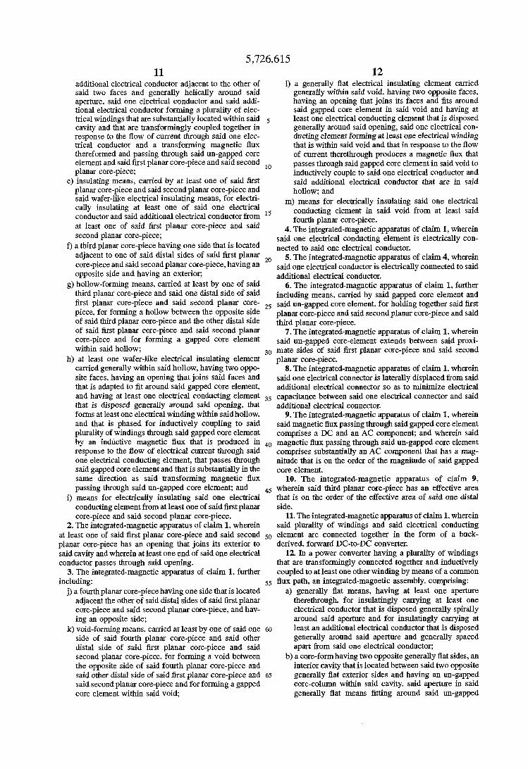
h) at least one wafer-like electrical insulating element planar core-piece. carried generally within said hollow. having two oppo- 8. The integrated-magnetic apparatus of claim 1. wherein site faces, having an opening that joins said faces and said one electrical connector is laterally displaced from said that is adapted to fit around said gapped core element, additional electrical connector so as to minimize electrical and having at least one electrical conducting element 35 capacitance between said one electrical connector and said that is disposed generally around said opening. that additional electrical connector. forms at least one electrical winding within said hollow. 9. The integrated-magnetic apparatus of claim 1, wherein and that is phased for inductively coupling to said said magnetic flux passing through said gapped core element plurality of windings through said gapped core element comprises a DC and an AC component; and wherein said by an inductive magnetic flux that is produced in 40 magnetic flux passing through said un-gapped core element response to the flow of electrical current through said comprises substantially an AC component that has a mag- one electrical conducting element, that passes through nitude that is on the order of the magnitude of said gapped said gapped core element and that is substantially in the core element. same direction as said transforming magnetic flux 10. The integrated-magnetic apparatus of claim 9, passing through said un-gapped core element; and 45 wherein said third planar core-piece has an effective area
i) means for electrically insulating said one electrical that is on the order of the effective area of said one distal conducting element from at least one of said first planar side. core-piece and said second planar core-piece. 11. The integrated-magnetic apparatus of claim 1. wherein
2. The integrated-magnetic apparatus of claim 1, wherein said plurality of windings and said electrical conducting at least one of said first planar core-piece and said second 50 element are connected together in the form of a buck- planar core-piece has an opening that joins its exterior to derived, forward DC-to-DC converter. said cavity and wherein at least one end of said one electrical 12. In a power converter having a plurality of windings conductor passes through said opening. that are transfodngly connected together and inductively
3. The integrated-magnetic apparatus of claim 1. further coupled to at least one other winding by means of a common including:
j) a fourth planar core-piece having one side that is located a) generally flat means, having at least one aperture adjacent the other of said distal sides of said first planar therethrough. for insulatingly carrying at least one core-piece and said second planar corepiece, and hav- electrical conductor that is disposed generally spirally ing an opposite side; around said aperture and for insulatingly carrying at
k) v o i d - f o d g means, carried at least by One of said one 60 least an additional electrical conductor that is disposed side of said fourth planar core-piece and said other generally around said aperture and generally spaced distal side of said first planar core-piece and said apart from said one electrical conductor; second planar core-piece. for forming a void between b) a core-form having two opposite generally flat sides. an the opposite side of said fourth planar core-piece and interior cavity that is located between said two opposite said other distal side of said first planar core-piece and 65 generally flat exterior sides and having an un-gapped said second planar core-piece and for forming a gapped core-column within said cavity. said aperture in said core element within said void generally flat means fitting around said un-gapped
1) a generally flat electrical insulating element carried generally within said void. having two opposite faces. having an opening that joins its faces and fits around said gapped core element in said void and having at least one electrical conducting element that is disposed generally around said opening, said one electrical con- ducting element forming at least one electrical winding that is within said void and that in response to the flow of current therethrough produces a magnetic flux that passes though said gapped core element in said void to inductively couple to said one electrical conductor and said additional electrical conductor that are in said hollow; and
m) means for electrically insulating said one electrical conducting element in said void from at least said fourth planar core-piece.
at least One Of said planar ‘Ore-Piece and said 4. The integrated-magnetic apparatus of claim 1, wherein
conductor.
55 flux path, an integrated-magnetic assembly. comprising:
5,726,615 13 14
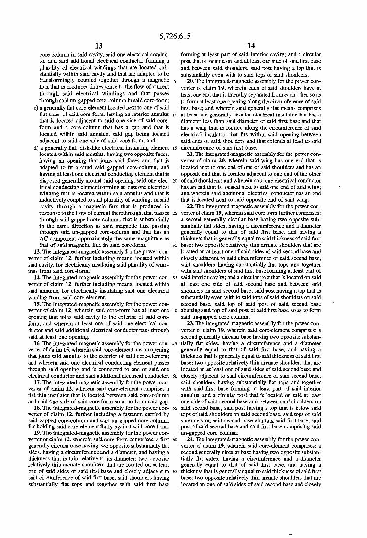
core-column in said cavity, said one electrical conduc- forming at least part of said interior cavity; and a circular tor and said additional electrical conductor forming a post that is located on said at least one side of said first base plurality of electrical windings that are located sub- and between said shoulders, said post having a top that is stantially Within said cavity and that are adapted to be substantially even with to said tops of said shoulders. W a n s f d g l Y coupled together through a magnetic 5 20. The integrated-magnetic assembly for the power con- flux that is produced in response to the flow Of Current verter of claim 19. wherein each of said shoulders have at though said electrical windings and that Passes least one end that is laterally separated fromeach other so as through said Un-gaPFd core-column in SaidcOre-fOm~ to form at least one opening along the circumference of said
c) a generally flat core-element located next to one of said first base; and wherein said generally flat means comprises flat sides of said core-form. having an interior annulus IO at least one generally circular electrical insulator that has a that is located adjacent to said one side of said core- diameter less than said diameter of said first base and that form and a core-column that has a gap and that is has a wing that is located along the circumference of said located within said annulus. said gap being located electrical insulator, that fits within said opening between adjacent to said one side of said core-form; and said ends of said shoulders and that extends at least to said
located within said annulus. having two opposite faces, 21. The integrated-magnetic assembly for the power con- having an opening that joins said faces and that is verter of claim 20, wherein said wing has one end that is adapted to fit around said gapped core-column, and located next to one end of one of said shoulders and has an having at least one electrical conducting element that is opposite end that is located adjacent to one end of the other disposed generally around said opening, said one elec- 20 of said shoulders; and wherein said one electrical conductor trical conducting element forming at least one electrical has an end that is located next to said one end of said wing; winding that is located within said annulus and that is and wherein said additional electrical conductor has an end inductively coupled to saidplurality of windings in said that is located next to said opposite end of said wing. cavity through a magnetic flux that is produced in 22. The integrated-magnetic assembly for the power con- response to the flow of current therethrough. that passes 25 verter of claim 19, wherein said core form further comprises: through said gapped core-column, that is substantially a second generally circular base having two opposite sub- in the same direction as said magnetic flux passing stantially flat sides, having a circumference and a diameter through said un-gapped core-column and that has an generally equal to that of said first base, and having a AC component approximately the same magnitude as thickness that is generally equal to said thickness of said first that of said magnetic flux in said core-fom 30 base; two opposite relatively thin arcuate shoulders that are
13. The integrated-magnetic assembly for the power con- located on at least one of said sides of said second base and verter of claim 12, further including means, located within closely adjacent to said circumference of said second base, said cavity, for electrically insulating said plurality of wind- said shoulders having substantially flat tops and together ings from said core-form with said shoulders of said first base forming at least part of
14. The integrated-magnetic assembly for the power con- 35 said interior cavity; and a circular post that is located on said verter of claim 12, further including means, located within at least one side of said second base and between said said annulus, for electrically insulating said one electrical shoulders on said second base, saidpost having a top that is winding from said core-element. substantially even with to said tops of said shoulders on said
15. The integrated-magnetic assembly for the power con- second base, said top of said post of said second base verter of claim 12, wherein said core-form has at least one 40 abutting said top of said post of said first base so as to form opening that joins said cavity to the exterior of said core- said un-gapped core column. form; and wherein at least one of said one electrical con- 23. The integrated-magnetic assembly for the power con- ductor and said additional electrical conductor pass through verter of claim 19, wherein said core-element comprises: a said at least one opening. second generally circular base having two opposite substan- 16. The integrated-magnetic assembly for the power con- 45 tially flat sides, having a circumference and a diameter
verter of claim 15, wherein said core-element has an opening generally equal to that of said first base, and having a that joins said annulus to the exterior of said core-element; thickness that is generally equal to saidthickuess of said first and wherein said one electrical conducting element passes base; two opposite relatively thin arcuate shoulders that are through said opening and is connected to one of said one located on at least one of said sides of said second base and electrical conductor and said additional electrical conductor. 50 closely adjacent to said circumference of said second base,
17. The integrated-magnetic assembly for the power con- said shoulders having substantially flat tops and together verter of claim 12. wherein said core-element comprises a with said first base forming at least part of said interior flat thin insulator that is located between said core-column annulus; and a circular post that is located on said at least and said one si& of said core-form so as to form said gap. one side of said second base and between said shoulders on
18. The integrated-magnetic assembly for the power con- 55 said second base, said post having a top that is below said verter of claim 12, further including a fastener, carried by tops of said shoulders on said second base, said tops of said said gapped core-column and said un-gapped core-column. shoulders on said second base abutting said first base, said for holding said core-element flatly against said coreform. post of said second base and said first base comprising said
19. The integrated-magnetic assembly for the power con- un-gapped core column. verter of claim 12. wherein said core-form comprises: a first 60 24. The integrated-magnetic assembly for the power con- generally circular base having two opposite substantially flat verter of claim 19. wherein said core-element comprises: a sides, having a circumference and a diameter, and having a second generally circular base having two opposite substan- thickness that is thin relative to its diameter: two opposite tially flat sides. having a circumference and a diameter relatively thin arcuate shoulders that are located on at least generally equal to that of said first base, and having a one of said sides of said first base and closely adjacent to 65 thickness that is generally equal to saidthickness of said first said circumference of said first base. said shoulders having base; two opposite relatively thin arcuate shoulders that are substantially flat tops and together with said first base located on one of said sides of said second base and closely
d) a generally flat. disk-like electrical insulating element 15 circumference of said first base.
5.726,615 15 16
adjacent to said circumference of said second base, said shoulders having substantially flat tops and together with said first base forming at least part of said interior annulus; a circular post that is located on said one side of said second base and between said shoulders on said second base, said 5 post having a top that is at the same elevation as said tops of said shoulders on said second base; and a flat thin insulator that is sandwiched between said top of said post of said second base and said first base to form said un-gapped core column. said tops of said shoulders on said second base 10 abutting said first base.
25. The integrated-magnetic assembly for the power con- verter of claim 19. wherein said shoulders have a width and said wing extends for a distance approximately to said width of said shoulders.
that in response to the flow of electrical current there- through and the magnetic flux thereformed and pass- ing through said gapped core element is inductively coupled to said at least one flat electrical winding and said at least one additional flat electrical winding and
that is phasedrelative to said one flat electrical winding and said one additional flat electrical winding to have said magnetic flux passing through said gapped core element substantially in the same direction as said magnetic flux passing through said un-gapped core element.
27. The integrated-magnetics of claim 26, wherein said 15 magnetic flux passing through said gapped core element
comprises a DC and an AC component; and wherein said magnetic flux passing through said un-gapped core element comprises substantially an AC component that has a mag- nitude that is on the order of the magnitude of said gapped
28. The integrated-magnetics of claim 27, further includ-
and said second printed circuit board means. for electrically insulating said at least one electrical winding
26. Integrated-magnetics. comprising: a) a first planar core-piece having two opposite sides and
having a perimeter; b) a second planar core-piece having two opposite sides 2o
and having a perimeter;
sides of said first planar core-piece and said second planar core-piece;
said perimeter of said first planar core-piece and said second planar core-piece and carried by at least one of said first planar core-piece and said second planar core-piece. for forming a flux path between said first planar core-piece and said second planar core-piece;
e) first printed circuit board means. located adjacent to said first planar core-piece and having an aperture that
least one flat electrical winding around said aperture; f) second printed circuit board means. located adjacent to 35
and spaced apart from said second planar core-piece and having an aperture that fits around said un-gapped core element. for carrying at least one additional flat electrical winding around said aperture, said at least one flat electrical winding and said at least one addi- 40 tional flat electrical winding being located substantially within said cavity and. in response to the flow of electrical current therethrough and the magnetic flux thereformed, being transformingly coupled together through said un-gapped core element and said flux-path 45 means;
g) a third planar core-piece having a perimeter and having a side that is located adjacent to one of said sides of said first planar core-piece;
h) means, carried by said third planar core-piece, for forming a gapped core element between said first planar core-piece and said third planar corepiece;
i) means. carried by said third planar core-piece, for forming a flux Path between said perimeter of said third 55 planar core-piece and said perimeter of said first Planar core-piece; and
j) third printed circuit board means, located between said first planar core-piece and said third planar core-piece and having an opening that fits around said gapped core 60
element.
c, an un-gamed Core piece carried between One Of ing means, located between said first printed circuit board
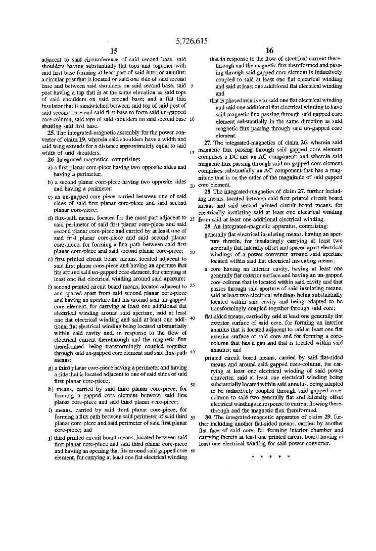
d) flux-path means, located for the most part adjacent to 25 from said at least one additional electrical winding. 29. An generally flat electrical insulating means, having an aper-
ture therein, for insulatingly carrying at least two generally flat, laterally offset and spaced apart electrical windings of a power converter around said aperture located within said flat electrical insulating means;
generally flat exterior surface and having an un-gapped core-column that is located within said cavity and that passes through said aperture of said insulating means. said at least two electrical windings being substantially located within said cavity and being adapted to be transfonningly coupled together through said core;
flat-sided means, carried by said at least one generally flat exterior surface of said core. for forming an interior annulus that is located adjacent to said at least one flat exterior surface of said core and for forming a core- column that has a gap and that is located within said
printed circuit board means, carried by said flat-sided means and around said gapped core-column, for car- rying at least one electrical winding of said power converter, said at least one electrical winding being substantially located within said annulus. being adapted to be inductively coupled through said gapped core- column to said two generally flat and laterally offset electrical windings in response to current flowing there- through and the magnetic flux thereformed.
30. The integrated-magnetic apparatus of claim 29. fur- ther including another flat-sided means. carried by another flat face of said core, for forming interior chamber and carrying therein at least one printed circuit board having at least one electrical winding for said power converter.
comprising:
30
fits around said un-gapped core element, for carrying at a 'Ore having an interior cavity, having at least One
and
50
element. for carrying at least one flat electrical winding * * * * *


![I11111 111ll111111 IIIII 11111 11111 1111111ll1 …...I11111 111ll111111 IIIII 11111 11111 1111111ll1 Ill11 11111 11111 11ll11111111111111 United States Patent 1191 USOO539398OA [11]](https://img.dokumen.tips/doc/110x75/5f03956a7e708231d409c50c/i11111-111ll111111-iiiii-11111-11111-1111111ll1-i11111-111ll111111-iiiii-11111.jpg)


![I11111 111111ll111 Ill11 Ill11 IIIII Ill11 Ill11 IIIII ...I11111 111111ll111 Ill11 Ill11 IIIII Ill11 Ill11 IIIII 11111 IIIII 11ll11111111111111 US006001426A United States Patent [19]](https://img.dokumen.tips/doc/110x75/5f08cf707e708231d423d4c6/i11111-111111ll111-ill11-ill11-iiiii-ill11-ill11-iiiii-i11111-111111ll111-ill11.jpg)