Embed Size (px)
Citation preview

“I hereby declare that I have read through this report entitle “Islanding Detection
Using Passive Reactive Power Imbalance Method” and found that it has comply the partial
fulfillment for awarding the degree of Bachelor of Electrical Engineering (Industrial
Power)”
Signature : ..............................................
Supervisor’s Name : Dr. Gan Chin Kim
Date : ……………………………..

ii
ISLANDING DETECTION USING PASSIVE REACTIVE POWER IMBALANCE
METHOD
REVINNATH A/L TENGGA DARAM
A report submitted in partial fulfillment of the requirements for the degree of
Bachelor in Electrical Engineering (Industrial Power)
Faculty of Electrical Engineering
UNIVERSITI TEKNIKAL MALAYSIA MELAKA
JUNE 2013

iii
I declare that this report entitle “Islanding Detection Using Passive Reactive Power
Imbalance Method” is the result of my own research except as cited in the references. The
report has not been accepted for any degree and is not concurrently submitted in
candidature of any other degree.
Signature: .....................................................
Name : Revinnath A/L Tengga Daram
Date : ………………………………….

iv
ACKNOWLEDGEMENT
First and foremost, I would like to thank god for His blessing. Without gods’ bless
I will not able to complete this research as required. Besides, the help and support from
certain groups and individual has encouraged me to finish up this project.
In conjunction, my deepest appreciation to Dr. Gan Chin Kim, my supervisor who
had given me endless help, guidance, and support me to make up with the standard as
required as an Electrical Engineer student during the final year project. His words and
kindness have kept me in orders for me make this project a valuable experience. Even
though I have to gone though many difficulties during the process to complete the project,
I have successfully finished my project. I also would like to say special thanks to my parent
because of their support in term of financial and advice.
Last but not least, thanks to all my friends for giving me support to obtain output of
this project and spending their time to share the knowledge and information related to my
project. All of the idea and opinion giving by them are very useful and effective to
develop and finish this project.
All the knowledge gained at Universiti Teknikal Malaysia Melaka present here in
my project report. Finally, I am indebted to all those people who have directly or indirectly
helped to make my final year report stint an incredible journey of knowledge and self-
improvement.

v
ABSTRACT
In this era of technology, usage of Micro-Grid at domestic areas has become a new
attraction due to its several advantages. The major function of a micro-grid is to ensure a
stable operation during the fault at a variety of utility grid disruption. Since the utilization
of micro-grid is becoming common, performing in the correct application and operation of
micro-grid is important and significant. One of the main challenges in micro-grid operation
is islanding detection method. There are several methods that handle the islanding
detection that each one of it has its own advantages and disadvantage. This paper presents
and investigates the reactive power imbalance method for islanding detection. It is one of
the passive methods used. This method was implemented in the case study because of it’s
simple, effective and low cost operation. However it has the higher non-detection zone
(NDZ) and slower response time compare to some active methods. The micro-grid
simulation is modelled in MATLAB/Simulink program and the results of the monitoring
are discussed as well. As the result, the performance of the Reactive Power Imbalance
method for islanding detection state is compared with the simulation model with various
load power factor. Finally, the micro-grid model capability with control algorithm is shown
in order to meet the load demand.

vi
ABSTRAK
Micro-grid merupakan salah satu sistem penjanaan kuasa yang berupaya untuk
beroperasi secara bersendirian supaya menampung beban terdekat. Keupayaan ini boleh
diaplikasi apabila sistem penghantaran kuasa mengalami sesar. Terdapat beberapa jenis
cara untuk mengesan kes-kes sesaran. Di antaranya adalah kaedah aktif, kaedah pasif,
kaedah komunikasi dan sebagainya. Kajian ini dilakukan atas kesan sesaran apabila micro-
gid berada dalam keadaan terpinggir dengan menggunakan kaedah pasif. Secara
terperinciri, kaedah pasif kuasa reaktif telah dikaji untuk menilai ciri-ciri beban pada factor
kuasa yang berbeza. Semakin tinggi nilai faktor kuasa hingga menghampiri uniti, semakin
kurang kesan penggunaan mikro-grid pada nilai kuasa aktif, kuasa reaktif, voltan fasa-ke-
bumi dan arus fasa-ke-bumi. Dengan pengunnan kaedah pasif kuasa reaktif, masa yang
diambil untuk memperbaiki kesan sesaran boleh ditentukan. Bagi mengkaji kaedah ini,
simulasi pada MATLAB/Simulink telah berupaya untuk membantu bagi menjayakan
kajian malah memudahkan proses pengambilan data pada setiap pembolehubah yang
digunakan.

vii
TABLE OF CONTENTS
CHAPTER TITLE PAGE
ACKNOWLEDGEMENT iv
ABSTRACT v
ABSTRAK vi
TABLE OF CONTENT vii
LIST OF TABLES ix
LIST OF FIGURES x
LIST OF SYMBOLS xii
LIST OF APPENDICES xiii
1 INTRODUCTION 1
1.1 Problem Statement 1
1.2 Objectives 2
1.3 Project Scopes 2
2 LITERATURE REVIEW 3
2.1 Project Background 3
2.2 Micro-Grid 3
2.3 Islanding state in Micro-grid 4
2.4 Passive Method 6
2.5 Reactive Power Imbalance 8
2.6 IEEE standards on Islanding Detection 8
3 METHODOLOGY 9
3.1 Procedure 10
3.2 Flow Chart 11
3.3 Case Study 12
3.4 Calculation of Reactive Power Detection Index (D) 19

viii
CHAPTER TITLE PAGE
4 RESULT 21
4.1 Detection Index 21
4.2 Load characteristics 23
5 ANALYSIS AND DISCUSSION 27
5.1 Analysis 27
5.2 Discussion 28
6 CONCLUSION 32
6.1 Conclusion 32
6.2 Recommendation 32
REFERENCES 34
APPENDICES 36

ix
LIST OF TABLES
TABLE TITLE PAGE
2.3.1 Comparisons of islanding detection characteristics 6
2.6.1 Clearing time standards on IEEE 1547 8
3.3.1 DG parameter 13
3.3.2 Utility grid parameter 14
3.3.3 Load parameter 14
3.3.4 Transformer 1 parameter 14
3.3.5 Transformer 2 parameter 15
3.3.6 Comparison of different load 15
5.1.1 Comparison of load characteristic on the occurrence of 27
controlling system
5.1.2 Comparison of various test load parameter at 28
different Condition
5.2.1 Percentage of load reduction between pre-fault and post-fault 29

x
LIST OF FIGURES
FIGURE TITLE PAGE
2.2.1 One line diagram of Micro-grid system 4
2.3.1 Islanding Detection Methods 5
2.4.1 NDZ of OVP/UVP and OFP/UFP 7
2.5.1 Discretization and calculation process of D 8
3.1.1 Micro-grid modelling diagram 9
3.2.1 Reactive Power Imbalance Algorithm 11
3.3.1 One line diagram of micro-grid for case study 12
3.3.2 Micro-grid model without controlling system 12
3.3.3 Micro-grid model with controlling system 14
3.3.4 Measurement system of Micro-grid without controlling system 16
3.3.5 Calculation coding of Detection Index (D) 17
3.3.6 Reactive Power Imbalance Monitoring (RPIM) system 17
3.3.7 Condition and Counter of RPIM 18
4.1.1 Detection Index without controlling system 21
4.1.2 (a) Detection Index, (b) Counter, and (c) Islanding Switch 22
Input for 0.8 power factor lagging
4.1.3 (a) Detection Index, (b) Counter, and (c) Islanding Switch 22
Input for 0.95 power factor lagging
4.1.4 (a) Detection Index, (b) Counter, and (c) Islanding Switch 23
Input for unity power factor
4.2.1 (a) active power (P) and reactive power (Q), 24
(b) phase-to-ground peak voltage (Vp) and
(c) phase-to-ground peak current (Ip) without
controlling system
4.2.2 (a) Active Power (P) and Reactive Power (Q), 25
(b) Phase-to-ground Peak Voltage (Vp) and
(c) Phase-to-ground Peak Current (Ip) at 0.8
lagging power factor

xi
FIGURE TITLE PAGE
4.2.3 (a) Active Power (P) and Reactive Power (Q), 25
(b) Phase-to-ground Peak Voltage (Vp) and
(c) Phase-to-ground Peak Current (Ip) at 0.95
lagging power factor
4.2.4 (a) Active Power (P) and Reactive Power (Q), 26
(b) Phase-to-ground Peak Voltage (Vp) and
(c) Phase-to-ground Peak Current (Ip) at unity
power factor
5.2.1 Clearing time for test load 30

xii
LIST OF SYMBOLS
Vp – Phase-to-ground Peak Voltage
Ip – Phase-to-ground Peak Current
P – Active Power
Q – Reactive Power
D – Detection Index
Dth
-- Detection Index Threshold Value
DG – Distributed Generation
RPIM -- Reactive Power Imbalance Monitoring
IS -- Islanding Switch
θ -- Phase angle between DG Voltage and DG Current
ø -- Phase angle between Load Voltage and Load Current
VDG -- DG Phase-to-ground Voltage
IDG -- DG Phase-to-ground Current
QDG -- DG Reactive Power
VLD -- Load Phase-to-ground Voltage
ILD -- Load Phase-to-ground Current
ZLD -- Load Impedance
YLD -- Load Admittance
IN -- Utility Grid Phase-to-ground Peak Current
SDG -- DG Short Circuit Level

xiii
LIST OF APPENDICES
APPENDIX TITLE PAGE
A Paper Publication at ICE-SEAM 2013 ` 36
B Micro-Grid Standards and Technology 43
C An Overview of Islanding Detection Methods in
Photovoltaic System 52
D A Review of Recent Development in Smart Grid and
Micro-Grid Laboratories 58
E Passive Anti-Islanding Scheme Based on Reactive
Power in the Smart Grids 65
1
CHAPTER 1
INTRODUCTION
The main energy provider in Malaysia is Tenaga Nasional Berhad (TNB). It is a
private company that is wholly owned by the government in 1990. Besides, there are also
two other national energy provider in Sabah and Sarawak such as Sabah Electricity
Sendrian Berhad (SESB) and Sarawak Electricity Supply Corporation (SESCO)
respectively [1]. Distributed Generation (DG) is a small scale power system that is
powered by the renewable energy to support the demand of electricity at local load.
1.1 Problem Statement
Problems occur when the power system happens to have fault during the
connection of the Distributed Generation (DG) to support the demand of the electricity at
the local load. If the fault is a three-phase line-to-ground fault, the supply from the national
grid and DG is grounded. This operation will lead to unintentional islanding for the DG
system. The project is to disconnect the utility line to supply power to the local load
meanwhile performing an operation to support the local load demand. Once it is
disconnected, the DG is in the islanding state because the local load is supplied by the DG.
This immediate system is known as micro-grid due to its islanding state that operates as a
standalone system. Unintentional islanding is a very hazardous state for the technical
workers during installation, as they do not acknowledge that the local load is still supplying
by the DG. Besides, the purpose of detecting the islanding mode is to prevent various
magnitudes of voltage and frequency being supply the equipment without bothering the
demand of the load. This project was to build a simulation circuit and performing a case
study during the three-phase line-to-ground fault condition in order to clear the fault
condition from affecting the local load.

2
1.2 Objectives
The three main objectives of analysing the Micro-grid operation are:
i. To detect islanding state of the micro-grid model using MATLAB/Simulink
ii. To detect a three-phase line-to-ground fault at the power system modelling
by using MATLAB/Simulink software.
iii. To model and monitor the Passive Reactive Power Imbalance method in
MATLAB/Simulink.
1.3 Project Scopes
The scopes of this project are:
i. Detect the islanding state using Passive Reactive Power Imbalance Method.
ii. The Micro-grid system is operated on a three-phase system of 400V and
frequency of 50Hz.
iii. The circuit is analysed for a three-phase line-to-ground fault condition.

3
CHAPTER 2
LITERATURE REVIEW
2.1 Project Background
The prime mover of the national energy providers are mostly non-renewable energy
such as coal and gas. Statistically, the usage of natural gas is 62.9%, coal is 26.7% and
10% usage of hydro-electric generation in 2007. 0.4% is a usage of other non-renewable
energy such as diesel and oil. Hydro-electric is one of the major renewable energy used as
prime mover according to the statistic [2].
The research of renewable energy is being analysed due to its ability to maintain
the supply of source continuously. The renewable energies available in Malaysia are solar,
wind and hydro but the installation of these sources as a prime mover in a big scale is very
expensive. In conjunction to make use of this renewable energy in national grid, it is built
in a small scale that supports the local load demand [2]. National grid is also known as
utility grid.
2.2 Micro-grid
Micro-grid is cheapest power systems that do not have a transmission line. Micro-
grid system is also known as a stand-alone system that has its own generator, transformer
and protection system. The generator of a micro-grid system is also known as Distributed
Generation (DG). DG is typically includes internal gas turbines, micro-turbines,
photovoltaic, fuel cells and many types of renewable energy [3].
At the normal condition, the demand of the load is being shared by the utility grid
and DG. Both grids are connected at the Point of Common Coupling (PCC) to share the

4
local load. The one line diagram of the power system mentioned before is illustrated at
Figure 2.2.1. When the fault occurs in the transmission line, the micro-grid will tend to
support the load demand as a whole automatically. This situation of the micro-grid is
known as unintentional islanding mode [3].
Figure 2.2.1: One line diagram of Micro-grid system [3]
2.3 Islanding State in Micro-Grid
Islanding mode has two types such as intentional and unintentional Islanding.
Intentional islanding happens with a planned shutdown of the utility grid during
maintenance whereby unintentional islanding mode happens during unplanned shutdown
of the utility grid due to occurrence of fault. This occurrence of unintentional islanding
mode is unknown because the load is still managing to supply power by the DG [4].
One of the most important issues occur at power system is when the utility grid
becomes unavailable. At this point of moment, the micro-grids should be eligible to active
its islanding state condition in order to continuously support and meets the local load
demand. It is important in terms of safety to let to the utility grid to stay in normal
operation and restore the power system.

5
The islanding detection methods are shown in Figure 2.3.1 that there are two
important categories of islanding detection techniques which are Local and communication
methods. Local methods are divided into major group such as passive and active methods.
On the other hand, communication methods are divided into two methods such as Power
Line Carrier Communication (PLCC) and Supervisory Control and Data Acquisition
(SCADA) [5].
Figure 2.3.1: Islanding Detection Methods [5]
The disadvantages of passive methods are being corrected by the active methods distortion
controller or positive feedback to the system. Communication methods are similar to the
passive method such as measuring the parameter on both utility and micro-grids but it the
measured parameters in communication methods is being send to the control room by
wireless, high speed LAN, broadband and mobile. The interfaces of the data transfer are
either PLCC or SCADA [5].
There are few advantages of connecting the micro-grid system with the utility grid
system at the PCC. A micro-grid system is flexible of locating DG nearer to the load area.
It is because DG is a small-scale power system grid and eliminates the transmission line of
the power system. On the other hand, due to low voltage supply from the renewable energy
is another reason for locating DG nearer to the load.
Islanding detection
Communication
methodsLocal
methods
SCADA PLCC Passive method Active method

6
Micro-grid is a beneficial power system grid because of its capability of improving
the reliability of power usage at load. It is a standalone grid that has the ability to support
the load demand when failure occurs at the utility grid system. In addition, micro-grid also
reduces transmission losses, reduces cost of cables to set up transmission network, reduces
the peak demand at national grid system, and defers the investment [6].
On the other hand, it also have disadvantages such as high maintenance cost, lesser
protection during fault for the load and intermittent grids, and it does not have a consistent
of power flow to the load. TABLE I shows the characteristics of various islanding
detection methods [7].
Table 2.3.1: Comparisons of islanding detection characteristics [7]
2.4 Passive Method
From the simple analysis of the characteristic table of each method of Table 2.3.1,
passive method is used to monitor the parameters at the PCC. Besides, to set up the system
of passive method is cheaper compared to the other methods mentioned in the
Characteristic Local detection method Remote detection method
Active
Method
Passive
Method
Utility Method Communication
Method
Operations Injection of
disturbance
signal at
parameters
Monitoring the
parameters at
PCC
Installing
specific
equipment at
utility
Installing
communication
equipment
Non Detection
Zone (NDZ)
Small Large None None
Response time Slightly
shorter than
passive
method
Short Fast Faster
System cost Medium Low Very high Extremely high

7
characteristic table above. Although the passive method is cheap, but it has a large portion
of non-detection zone (NDZ) and the response time is much slower than the other three
methods such as active method, utility method and communication based method [7].
Passive methods are based on measuring some parameters of the power system at
Point of Common Coupling (PCC) and analysis them to detect the islanding. Each
parameter has certain range and normal operation. If the measured value is not satisfied
with the range the algorithm that is set, the system will detect the islanding condition of the
Micro-grid. The measured parameters can be voltage, current, frequency, active power and
reactive power [8].
Over/Under Voltage Protection (OVP/UVP) and Over/Under Frequency Protection
(OFP/UFP) are the basic passive method that commonly used in islanding detection. It is
used by monitoring the voltage and frequency at the PCC. The real and reactive power
zones and Non-Detection Zones (NDZ) of OVP/UVP and OFP/UFP is illustrated at Figure
2.4.1 below [9].
Figure 2.4.1: NDZ of OVP/UVP and OFP/UFP [9]

8
2.5 Reactive Power Imbalance
The reactive power imbalance applying in the passive method is the rate of change
of distribution generator (DG) voltage over the rate of change of reactive power at load.
The value is known as Detection Index (D) as stated in Figure 2.5.1. To perform the
calculation of D, the continuous signal is transform into discrete signal. Similar method is
used on the product currently present in the market is the ROCOV relay [10].
Figure 2.5.1: Discretization and calculation process of D [10]
2.6 IEEE standards on Islanding Detection
According to IEEE 1547 Standard of Interconnecting Distributed Resources with
Electric Power Systems, the fault clearing time of the power system should follow the
standards given in the Table 2.6.1.
Table 2.6.1: Clearing time standards on IEEE 1547
Voltage range (% of base voltage) Clearing time(s)
V < 50 0.16
50 ≤ V ≤ 88 2.00
110 ≤ V ≤ 120 1.00
V ≥ 120 0.16
9
CHAPTER 3
METHODOLOGY
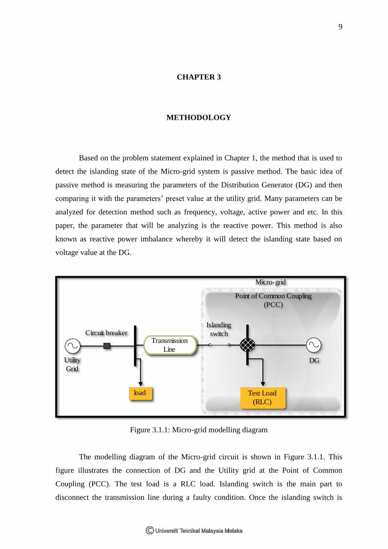
Based on the problem statement explained in Chapter 1, the method that is used to
detect the islanding state of the Micro-grid system is passive method. The basic idea of
passive method is measuring the parameters of the Distribution Generator (DG) and then
comparing it with the parameters’ preset value at the utility grid. Many parameters can be
analyzed for detection method such as frequency, voltage, active power and etc. In this
paper, the parameter that will be analyzing is the reactive power. This method is also
known as reactive power imbalance whereby it will detect the islanding state based on
voltage value at the DG.
Figure 3.1.1: Micro-grid modelling diagram
The modelling diagram of the Micro-grid circuit is shown in Figure 3.1.1. This
figure illustrates the connection of DG and the Utility grid at the Point of Common
Coupling (PCC). The test load is a RLC load. Islanding switch is the main part to
disconnect the transmission line during a faulty condition. Once the islanding switch is
Circuit breaker
Utility
Grid
Transmission
Line
load
Islanding
switch
Micro-grid
Point of Common Coupling
(PCC)
DG
Test Load
(RLC)

10
open, automatically the micro-grid is in the islanding state because the test load is fully
supported by DG.
3.1 Procedure
The procedure begins by measuring the three-phase voltage (V), and three-phase
current (I) at the Utility grid, Load and DG. Then the value of Active power (P)and
reactive power (Q) at load and DG is calculated. The signals of V, I, P and Q is then
converted to discrete by using the Zero-Order Hold (ZOH) filter. The calculation of
Detection index (D) is performed after the conversion process. D is calculated as D=
[8], will be explained in section 3.3, Calculation.
Once the value of D is obtained, it is then compared with the threshold value of Dth
.
The Dth
is set as one. If the amplitude of D is larger than the Dth
, then number of counter, N
will increase by one and will repeat the process until the total counter, Nth
is met by the
counter system. The value of Nth
is set according to how fast was the detection time is
needed. The lesser of Nth
, the faster the system will tend to perform islanding state of
micro-grid. If Nth
is set as five, the islanding switch will trip the connection of utility grid
from the local load at the fifth counter. At this point, the local load is connected to the
micro-grid as in an islanding state.
If the value of D is lesser than one, the counter will not operate. At this point, there
will be a feedback loop to repeat the initial procedure of measuring the parameter. Every
counter the system will repeat the parameter measuring process until the counter reaches
Nth
.
During islanding state the local load is supplied with the same amount of reactive
and active power that does not affect the load. The transition time of the power system
from the non-islanding state to islanding state is dependent on the Nth
value of the counter.
According to IEEE 1547 standard the reconnection time of the local load to the supply
should be within 0.16 second [11]. The simulation of the micro-grid is done over the
MATLAB/ Simulink software.

11
3.2 Flow Chart
.
Figure 3.2.1: Reactive Power Imbalance Algorithm
The procedure explained in sub-topic 3.1 is illustrated in a flow chart in Figure
3.2.1. The output of the flow chart is the status of the islanding switch either open or close.
Open status meaning that the utility grid is disconnected from the PCC meanwhile close
status of the islanding switch meaning that the load is still supported by the Utility grid.
Measuring the voltage, Current, Active power and
Reactive power at the Test Load, DG and Utility grid
Zero-Order Hold
Filter
Calculation of
detection index
(D)
D>DthN=0
N>Nth
Trip Islanding Switch
N=N+1