Embed Size (px)
Citation preview

i
GAS RETICULATION SYSTEM DESIGN FOR UNIVERSITI MALAYSIA
PAHANG GAMBANG CAMPUS
SHAFIQ AFIF BIN ARIFF
A report submitted in partial fulfillment of the
requirements for the award of the degree of
Bachelor of Chemical Engineering (Gas Technology)
Faculty of Chemical Engineering & Natural Resources
University Malaysia Pahang
MAY, 2008

“I declare that I have read this thesis and in my opinion this thesis is adequate in terms
of scope and quality for the purpose awarding a Bachelor’s Degree of Chemical
Engineering (Gas Technology).”
Signature : ...........................................................
Supervisor : Associate Professor Zulkafli Bin Hassan
Date : 13 May 2008
iv
I declare that this thesis entitled “Gas Reticulation System Design For Universiti
Malaysia Pahang Gambang Campus” is the result of my own research except as cited
in the references. The thesis has not been accepted for any degree and is not
concurrently submitted in candidature of any other degree.
Signature : ……………………………………..
Name : Shafiq Afif Bin Ariff
Date : 12 May 2008

v
ACKNOWLEDGEMENTS
I would like to thank my supervisor Associate Professor Zulkafli Bin Hassan
for his insightful comments and suggestions on reading material as I endeavored to
produce this report. His enthusiasm and ideas on the topic encouraged me come out
with the design for gas utilization system in UMP at a time when all I could think
inside of my mind was a monumental disarray of ideas. My co-supervisor Mr. Arman
Bin Abdullah and my vocational training officer Mr. Mohd Masri Bin A. Razak have
been a great source of information on gas engineering studies and have given me
helpful contacts. They were instrumental in the production of my final report and
encouraged me to pursue it, even when I wasn't quite sure what contribution I could
make through it. My parent and Faraliza Bte Nordin, they all are the roots of my
spiritual and diverting me from the potentially frustrating to a good grasp of this
project. They relentless pursuit of words that poetically describe ideas sparked in me
a desire to improve my own writing and their wholehearted support of this project.
For my project partner, Mohd Sallehan Bin Abdul Rahman who has been
instrumental in helping me polishes my ideas on this project. Not forget all my fellow
friends who help me in sharing ideas and completing this project. Thanks a lot for all
the ideas and support that you all gave to me.

vi
ABSTRACT
The main objective of this project is to design a distribution system for
natural gas and LPG to the facilities in Universiti Malaysia Pahang (UMP). This
system will be designed to take into account of the potential use of natural gas and
LPG in UMP such as for combine heat power (CHP) unit, air conditioning, and gas
consumption unit. Gas either natural gas and LPG are direct source of energy which
is more cost effective as compared to electricity per unit of energy value utilized.
UMP is a small campus with approximately consists of 4000 students. The location
of UMP is near to the transmission line or gas source and also next to future bio
based industrial development. With the existing transmission line in PGU 1 and the
nearest city gate in Gambang, it is a convenient way to tap the natural gas from city
gate to Universiti Malaysia Pahang. In UMP also has gas engineering lab that require
natural gas and LPG as feed fuel for it equipments to operate. The objectives of
study are to design a utilization system and to analyze the feasibility of the system to
achieve the overall target decided earlier. The electricity bill is higher which
consumed by air conditioner in lab, classrooms, offices, and etc. Thus, there is a
need to identify alternative energy source to plant campus that is cheaper, safe, and
efficient. It is also to set benchmark or working example of an energy efficient
system. The scopes of this project are to design the reticulation system, to determine
the gas consumption and demand, and to calculate the cost of this project which
specific for piping cost and construction. The method that been used are to calculate
all the piping size and gas load demand by using certain formula according to
standard such as MS930 and ASME B31.8. Gapis Software is to verify the manual
calculation that already made either correct or not.

vii
ABSTRAK
Objektif utama projek ini adalah untuk melakar satu sistem pengagihan untuk
gas asli dan gas petroliam cecair ke kemudahan di Universiti Malaysia Pahang
(UMP). Sistem ini akan dilakarkan untuk kegunaan alat yang menggunakan gas asli
dan gas petroliam cecair seperti “combine heat power (CHP) unit dan penghawa
dingin. Gas sama ada gas asli dan gas petroliam cecair adalah tenaga sumber terus
yang mana adalah lebih efektif kos untuk dibandingkan dengan kos elektrik untuk
satu unit nilai tenaga yang diutilitikan. UMP adalah sebuah kampus yang kecil yang
mempunyai lebih kurang 4000 pelajar. Lokasi UMP adalah berdekatan dengan talian
transmisi atau sumber gas dan juga bersebelahan dengan pembangunan industri
berasaskan bio. Dengan adanya talian transmisi yang sedia ada dan juga “city gate”
yang berdekatan di Gambang, ianya adalah jalan yang mudah untuk menyedut gas
asli dari “city gate” ke Universiti Malaysia Pahang. Di UMP juga terdapat makmal
kejuruteraan gas yang memerlukan gas asli dan gas petroliam cecair sebagai gas
masuk untuk peralatan berfungsi. Objektif belajar adalah untuk melakar satu sistem
utiliti dan untuk membuat analisis tentang keberkesanan sistem tersebut untuk
mencapai target keseluruhan yang telah ditentukan awal. Bil elektrik adalah sangat
tinggi dimana digunakan oleh alat penghawa dingin di makmal, kelas, pejabat, dan
sebagainya. Oleh itu, ini memerlukan satu alternatif sumber tenaga pada kampus
yang murah, selamat, dan effisien. Ianya juga untuk menjadikan sebagai penanda
aras atau contoh pekerjaan untuk sistem tenaga yang effisien. Skop projek ini adalah
untuk melakar sistem retikulasi, untuk menentukan penggunaan gas dan keperluan,
dan untuk mengira kos projek dimana spesifik kepada kos paip dan pembinaan.
Kaedah yang digunakan adalah mengira semua ukuran paip dan keperluan gas
dengan menggunakan rumus yang berkaitan mengikut piawai seperti MS930 dan
ASME B31.8. Perisian Gapis adalah untuk membuktikan kiraan manual yang telah
dibuat benar atau tidak.

viii
TABLE OF CONTENTS
CHAPTER TITLE PAGE
TITLE PAGE i
DECLARATION OF ORIGINALITY
AND EXCLUSIVENESS ii
DECLARATION iv
ACKNOWLEDGEMENT v
ABSTRACT vi
ABSTRAK vii
TABLE OF CONTENTS viii
LIST OF FIGURES xi
LIST OF TABLES xii
1 INTRODUCTION 1
1.1 Background of study 1
1.2 Problem statement 2
1.3 Objectives of the project 3
1.4 Scope of research work 3
2 GAS TRANSMISSION & DISTRIBUTION
SYSTEM DESIGN 5
2.1 Introduction of Gas System 5
2.2 Properties of Fuel Gas 6
2.2.1 Natural Gas 6
2.2.2 Liquefied Petroleum Gas 7

ix
2.3 Transmission System 8
2.3.1 City Gate Station 9
2.4 Distribution System 10
2.4.1 Specifications and Functions of
Station Design 12
2.4.2 Basic Layout of District Station and
Service Station 15
2.4.3 Distribution of Liquefied Petroleum Gas 17
2.4.4 Design of Pipeline 18
2.5 Standards And Codes 20
2.5.1 Design, Installation, And Testing 20
2.5.2 Class Locations 20
2.5.3 Protection of Pipelines and Mains From
Hazards 21
2.5.4 Clearance Between Pipelines or Mains
and Other Underground Structures 22
2.5.5 Allowable Maximum Operating Pressure 22
2.5.6 Maximum Design Operating Pressure 22
2.5.7 Piping Underground 23
2.5.8 Piping Underground Beneath Building and
Protection Against Corrosion 24
2.5.9 Sizing of Gas Piping Systems 25
2.6 Universiti Malaysia Pahang Campus Layout 25
2.7 Gas Piping Simulator 28
3 METHODOLOGY 30
3.1 Solving Techniques 30
3.1.1 Using GAPIS ver2.3 33
4 RESULTS AND DISCUSSIONS 35
4.1 Results 35
4.2 Discussion 41

x
5 CONCLUSION AND RECOMMENDATIONS 46
5.1 Recommendations 47
LIST OF REFERENCES 48
Appendices 50-73

xi
LIST OF FIGURES
FIGURE NO. TITLE PAGE
2.1 Outline of gas Malaysia natural gas supply system 11
2.2 Layout of district station 15
2.3 Layout of service station 16
2.4 Layout of LPG distribution outline 17
2.5 Map Overview of Universiti Malaysia Pahang 27
3.1 Flow chart of overall piping design 31
3.2 Screen dump of GAPIS Software for formula selection 33
3.3 Example of proposed piping layout using
GAPIS for UMP distribution system 34
4.1 Pipe route selection branch type with looping 36
4.2 Pipe route selection branch type without looping 37
4.3 Results of piping layout with data input by using GAPIS 38

xii
LIST OF TABLES
TABLE NO. TITLE PAGE
2.1 Specifications of station design 13
2.2 Function of district and service stations 14
2.3 Class location definitions in constructing of gas pipeline 21
2.4 Advantages and disadvantages of using GAPIS ver2.3 29
4.1 Result of data input of piping layout which consists
of length and diameter of the pipe 39
4.2 Result of data input of piping layout which consists
of load demand, pressure and pressure drop of the pipe 40
4.3 Gas meter pricing 44
4.4 Pipe pricing 45

1
CHAPTER 1
INTRODUCTION
1.1 Background of study
The attraction to convert to natural gas utilization over other fuels including
the electricity is because the reliability and stability of piped natural gas supply as
compared with other fuels. In term of transmission line, if compared to electricity,
the electric power in current from power plant to the customer will loss at the
transmission line and need a generator to power up the current. The efficiency of
power plant is below 40% and this is why the electricity cost is higher and expensive.
For natural gas, the gas will flow through the transmission line in stability and
continuously without having loss of load. The use of natural gas, a clean environment
friendly fuel has contributed to a reduction in emissions. With increasing
environmental consciousness and responsibility on the part of industries in Malaysia,
the benefit as becoming an important consideration in future and a step forward
towards sustainable development for the country.
As the fuel of the future, natural gas has received ardent support in the
development of other areas of applications. A number of the new and improved
applications of natural gas have been successfully implemented in the market. Some
of the applications, however, have yet to be commercially viable even though they are
technically proven. The viability of these applications depends among others, on
equipment cost, alternative fuel cost and local regulatory conditions.

2
1.2 Problem statement
UMP is a small campus with approximately consists of 4000 students. All of
the lecture hall, classrooms, and offices are using air conditioner and for the
laboratory, the chiller unit consumed lots of electricity to operate. In FKKSA Lab
also, there are boiler and absorption chiller which are currently using electricity to
operate, thus the cost of operation is really expensive. Thus, from these equipments
will lead to the high cost electricity bill for UMP every month. But if using the
natural gas for this equipment, the cost of operation will reduce and are cheaper than
using electricity. The location of UMP is near to the transmission line or gas source
and also next to future bio based industrial development. With the existing
transmission line in PGU 1 and the nearest city gate in Gambang, it is a convenient
way to tap the natural gas from city gate to Universiti Malaysia Pahang. In UMP also
has gas engineering lab that require natural gas and LPG as feed fuel for it
equipments to operate. In Universiti Malaysia Pahang, there are few of laboratories
and building that are potential to develop a gas center that using a natural gas. The
Combined Heat Power (CHP) in FKKSA Lab currently using compressed natural gas
(CNG) which is in bulk storage. When the CHP running, all the CNG are fully used
and there is not enough supply of natural gas for the next run. Then, the CNG needs
to be refill and to refill the CNG, need to order and to wait for the delivery. In term
of time, it’s not worthy. In additional, in FKKSA Lab, the gas house which is
consists of gas consumption equipment is already built and the construction of gas
natural is reasonable for that situation. For the student cafeteria, currently they are
using the LPG bulk storage for cooking. For same situation, the LPG is only in a
bulk storage and not a continuous supply like natural gas, therefore they need to get a
new LPG bulk storage when the current LPG is going to finish. In Universiti
Malaysia Pahang map and FKKSA Lab map, there is a future development which is
potentially that the new development will need or use the natural gas.

3
1.3 Objectives of the project
The objectives of this project are :
1. To design a gas reticulation system in Universiti Malaysia Pahang
Campus .
2. To ensure this system is compatible for natural gas as well as LPG
3. To make an economic assessment on this design
4. To meet a safety requirement in the system
1.4 Scope of research work
In order to achieve the objective, the following scopes of research work have
been made:
1. The gas demand
The usage and consumption of gas in Universiti Malaysia Pahang.
The major part of gas consumption is Combined Heat Power (CHP) and other
equipment in FKKSA Lab and student cafeteria. And also for the future
development in Universiti Malaysia Pahang that will use natural gas.
2. The design pipe routing
By referring to the Universiti Malaysia Pahang Map and other relevant
information, the network piping calculation can be made by calculating the
loads of consumption using a certain formula and also determine the
classification of steel-pipe construction either use type A, B, C, or D
construction. The GaPis software is been used to draft and draw pipeline and
to choose the most reasonable piping network drawing.

4
3. Cost
The capital cost of natural gas construction which is including current
prices of natural gas and the current price of pipeline. It is the most effective
when the cost of gas construction is small and at the same time the safety
aspect is attached together. In short, safety aspect is included with low cost of
gas construction.
5
CHAPTER 2
GAS TRANSMISSION & DISTRIBUTION SYSTEM DESIGN
2.1 Introduction of Gas System
In gas system design, there are two categories of system which are
transmission and distribution. For transmission, it only refer to natural gas where the
natural gas will deliver from upstream to downstream by using transmission line.
Meanwhile for distribution, it can consist of natural gas and liquefied petroleum gas.
Distribution is where the fuel either natural gas or liquefied petroleum gas is
distributed to consumer.
The hydrocarbon route is started from the gas reservoirs which is consists of
either non associated gas or associated gas. Then, from the wellhead which the
drilling process is undergo, this gas will suck out and will through the process of
gas/liquid separation and gas treating. These process are being done at the oil
platform at the offshore. The treated gas then will compressed and will deliver and
transfer to the onshore gas processing plant via subsea pipeline transmission. At gas
processing plant, this gas will undergo separation process under distillation column.
After the distillation process finished and the natural gas is collected, then the natural
gas will compressed back and will distribute to the market and consumer. The natural
gas will delivered from gas processing plant to gas markets via transmission line and
will distributed to consumer after the city gate via distribution line.

6
For distribution of liquefied petroleum gas (LPG), it is not using any
transmission or distribution pipeline to deliver to consumer. This is because LPG is
in liquid form thus it is stored inside a tank which is either bulk storage or manifold
tank and it is delivered to customer via a lorry tanker. From the manifold system or
bulk system, LPG is distributed via a pipeline which is consists of 1st stage regulator,
2nd
stage regulator, valves, and meters before connected to the internal piping for
residential, commercial, and industrial customers.
2.2 Properties of Fuel Gas
There are 2 types of fuel gas that will use in this project which are natural gas
and liquefied petroleum gas. One of the fuel that mentioned will be use as alternative
fuel or backup fuel. In this project, the main fuel that will use is natural gas.
Therefore, the liquefied petroleum gas will be the alternative fuel or backup fuel.
2.2.1 Natural Gas
Natural gas is made up chiefly of the paraffin (alkenes CnH2n + 2) compound
methane (CH4). It may also contain ethane (C2H6), propane (C3H8), butane (C4H10)
and others. Unlike other fossil fuels, natural gas contains no sulphur and non-reacting
ash/dust and is an ideal fuel. Natural gas is a mixture without fixed composition.
Ersoz et al. (2006) studied that natural gas (methane, ethane, propane, and
butane) was the most famous and the best fuel for hydrogen rich gas production due
its composition from lower molecular weight. They found that the highest fuel
processing efficiency was achieved with natural gas steam reforming at about 98%.

7
Natural gas is a major source of electricity generation through the use of gas
turbines and steam turbines. Particularly high efficiencies can be achieved through
combining gas turbines with a steam turbine in combined cycle mode. Natural gas
burns cleaner than other fossil fuels, such as oil and coal, and produces less carbon
dioxide per unit energy released. For an equivalent amount of heat, burning natural
gas produces about 30% less carbon dioxide than burning petroleum and about 45%
less than burning coal.
Combined cycle power generation using natural gas is thus the cleanest source
of power available using fossil fuels, and this technology is widely used wherever gas
can be obtained at a reasonable cost. Fuel cell technology may eventually provide
cleaner options for converting natural gas into electricity, but as yet it is not price-
competitive. Also, the natural gas supply is expected to peak around the year 2030,
20 years after the peak of oil. It is also projected that the world's supply of natural
gas could be exhausted around the year 2085.
2.2.2 Liquefied Petroleum Gas
Liquefied Petroleum Gas (LPG) is a subcategory of petroleum products
known as natural gas liquids that are produced along with and extracted from natural
gas. The composition of LPG is either mixture of 70% butane 30% propane or 60%
butane 40% propane [16]
depends on the situation or culture of certain country. LPG
is also produced from the refining of crude oil via separation process in gas
processing plant. LPG recovered from natural gas is free of unsaturated
hydrocarbons such as propylene and butylenes. Much of propylene and butylenes are
removed in the refinery to provide raw materials for plastic and rubber production
and to produce high octane gasoline components.

8
LPGs are both volatile and flammable and must be stored and handled in
special equipment such as bulk storage and tank. Standards for storing and handling
LPG are published in Malaysia Standard (MS 830) Code of Practice For The Storage,
Handling and Transportation of LPG.
2.3 Transmission System
Natural gas is transported to market by long-distance pipelines. The design
and construction of these pipelines is of interest, as well as of the compressor stations
which provide the motive power. Protection from corrosion is an important aspect in
completing a project. Once the gas has reached the market area, it is often sold to a
distributor through a city gate station. Pressure regulation, metering, and odorization
normally take place at this point. Gas flows through low-pressure distribution
systems to the domestic and commercial market.[4]
In transmission pipeline, the
standards that has been referred are based on ASME B31.8 and MS 930.
In Malaysia, natural gas is delivered in form of crude oil to the gas processing
plant in Kerteh. There, natural gas was processed and then is distributed to all over
Peninsular Malaysia via transmission line known as Peninsular Gas Utilization
(PGU). There was Gas Transmission Operations Centre in Segamat under Petronas
Gas Berhad which monitored and analyzed the natural gas starting from GPP in
Kerteh throughout Peninsular Malaysia. From the transmission line, natural gas then
is distributed to consumer via distribution pipeline which is starting from the last
flanged of city gate to the gas consumer. [5]
With tremendous expansion of markets for natural gas in the past few years,
the concept of pipeline design has changed considerably. Formerly, a pipeline to
supply a specific market was designed to handle its present load plus a moderate
growth of perhaps 15 to 30 percent. Today, a pipeline is designed at maximum
diameter, with a minimum number of compression stations in order not to exceed a
reasonable unit transportation cost at the present market demand. [4]

9
For the transmission pipeline which is in high pressure, the formulas that
always been used are the Panhandle, Fritzsche’s, Fully Turbulent, Mueller, IGT
Distribution, Spitzglass, and Weymouth. The Panhandle formula or slight
modifications of it are in most common use in the natural gas industry for design of
cross-country pipelines and transmission pipelines.
The formula for Panhandle is :
(2-1)
(Cornell et. al., 1959. Transmission to Market. In: Handbook of Natural Gas
Engineering. New York: McGraw Hill. 625-654)
Where :
Q = flow rate measured at T0 and P0, cu ft/day
E = pipeline efficiency
T0 = temperature base, 0R
P0 = pressure base, psia
P1 = inlet pipeline pressure, psia
P2 = outlet pipeline pressure, psia
G = gravity of gas
T = mean flowing temperature, 0R
L = length of pipe, miles
d = internal pipe diameter, in.
2.3.1 City Gate Station
The purpose of city gate station is to meter gas volumes delivered, control
pressures by regulation, and introduce the proper quantity of odorant into gas stream.
Proper selection of the number, capacity, and location of city gate station depends
upon the overall transmission, storage, and distribution system design.

10
A city gate station must be designed carefully. It is the source of supply to the
distribution system and the cash register for the local utilities’ gas purchase. In
general, large distribution systems should be supplied from two or more stations, so
that the outage of one station can be offset by the operation of emergency capacity in
the other stations. High pressure transmission mains within populated areas must
meet extra and costly material specifications under the 1955 ASA B31.1 code for
pressure piping. Location of terminal points of high pressure transmission mains at
city gate station must consider present and future real estate development. Location
must also be considered for availability of electricity, telephone and accessibility by
adequate roads.[4]
2.4 Distribution System
Mains, services, and meters required to distribute gas to the ultimate
consumers constitute the gas distribution system. The design of new systems and
additions to and renewals of existing systems is a branch of gas engineering in itself.
The primary objective of a good design is to able to supply the market demand of any
customer in the system with a minimum capital investment consistent with sound
safety practices. [4]
The ultimate in successful design is to able to offer adequate gas service
economically to any customer within the service or franchised area. The degree to
which a distribution system fails to provide such service reflects upon the
engineering-design practices of the utility involved. [4]

11
Figure 2.1 : Outline of gas Malaysia natural gas supply system.
(K. Yamaguchi, 1994. Outline of Gas Malaysia Natural Gas Supply System.
In: Gas Malaysia Sdn. Bhd. Technical Department. Malaysia.)
In designing a pipeline network, various types of formulas have been used.
Normally, for distribution pipelines, the formulas that always been used are Pole,
NFPA54, Clifford, and Cox’s. Depending on certain gas company, specific formula
is been used. For PETRONAS Bhd., it used the Fully Turbulent Formula in
designing their transmission pipelines which is PGU. For Gas Malaysia Sdn. Bhd.
which handling in distribution of gas is using Cox’s and NFPA 54 as formula in
designing the pipelines. [1] [3] [5]
Methods widely used to solve the gas distribution pipe sizing are :
1) NFPA No. 54 (National Fire Protection Association) (MS 930)
2) Clifford Method (MS 930)
3) Cox’s Formula
4) Pole’s Formula
12
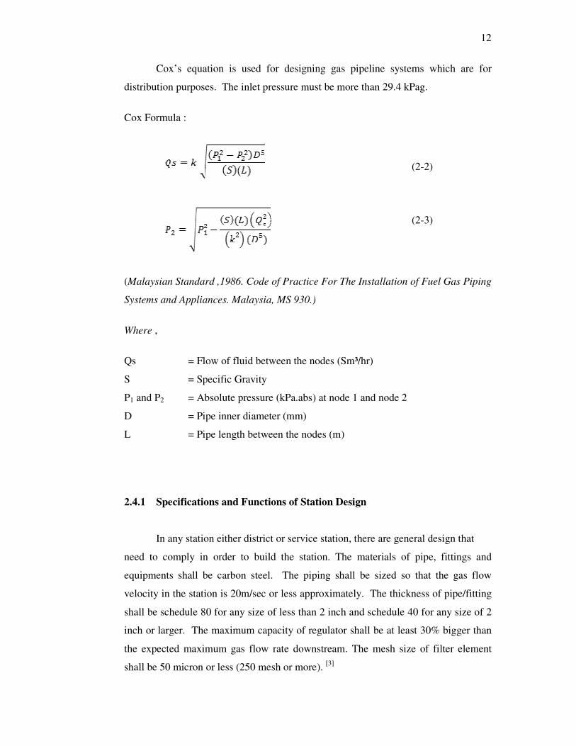
Cox’s equation is used for designing gas pipeline systems which are for
distribution purposes. The inlet pressure must be more than 29.4 kPag.
Cox Formula :
(2-2)
(2-3)
(Malaysian Standard ,1986. Code of Practice For The Installation of Fuel Gas Piping
Systems and Appliances. Malaysia, MS 930.)
Where ,
Qs = Flow of fluid between the nodes (Sm³/hr)
S = Specific Gravity
P1 and P2 = Absolute pressure (kPa.abs) at node 1 and node 2
D = Pipe inner diameter (mm)
L = Pipe length between the nodes (m)
2.4.1 Specifications and Functions of Station Design
In any station either district or service station, there are general design that
need to comply in order to build the station. The materials of pipe, fittings and
equipments shall be carbon steel. The piping shall be sized so that the gas flow
velocity in the station is 20m/sec or less approximately. The thickness of pipe/fitting
shall be schedule 80 for any size of less than 2 inch and schedule 40 for any size of 2
inch or larger. The maximum capacity of regulator shall be at least 30% bigger than
the expected maximum gas flow rate downstream. The mesh size of filter element
shall be 50 micron or less (250 mesh or more). [3]

13
Table 2.1 : Specifications of station design [5]
District Station Service Station
a) The combination of worker and
monitor regulators shall be
applied.
b) The worker shall be of unloading
type while the monitor shall be of
loading type.
c) Relief valve with 100% capacity
shall be used as an overpressure
protection device.
d) The set point of relief valve shall
be 10% higher than that of
monitor regulator.
e) The minimum difference in set
points between main and stand-by
workers shall be 5 psi.
f) The set point of main monitor
shall be equal to that of stand-by
monitor.
a) The single stream system with
by-pass line shall be applied
basically.
b) The slam shut valve shall be used
basically as an overpressure
protection device. The set point
of slam shut valve shall be 50%
higher than that of worker.
c) The monitor regulator may be
used as an overpressure
protection device instead of slam
shut valve when the continuous
supply is taken into consideration
seriously.
d) The relief valve with 10%
capacity shall be used to partially
discharge the overpressure to
atmosphere. It will effective for
small and temporary
overpressure.
e) Y-strainer shall be installed the
inlet size of gas meter.
f) Turbine type gas meter shall be
employed basically because it is
economical and strong against the
dust in supplied gas. Rotary type
gas meter may be employed for
commercial and small industrial
customers.
The function of station is to reduce the upstream supply pressure and to
control the downstream pressure at constant irrespective of fluctuation of gas
consumption volume by customer.

14
Service station is installed in the customer’s premises to supply gas to the one
concerned customer. District station is installed in the road reserve to supply gas to
multiple customers through distribution/service line and service station downstream.
Table 2.2 : Function of district and service stations.[5]
District Station Service Station
1. Control the downstream pressure
at the pre-adjusted pressure
irrespective of gas consumption
volume and upstream pressure
fluctuations.
2. Trap Dust, grease and other
foreign materials included in the
supply gas.
3. Discharge all of supply gas to
atmosphere for safety when the
downstream pressure exceeds the
pre-determined level due to
regulator failure. (100% relief).
4. Record the upstream and
downstream pressure for
operation/maintenance purpose.
1. Control the downstream pressure
at the pre-adjusted pressure
irrespective of gas consumption
volume and upstream pressure
fluctuations.
2. Trap Dust, grease and other
foreign materials included in the
supply gas.
3. Discharge some amount of supply
gas to atmosphere for safety when
the downstream pressure exceeds
the pre-determined level due to
regulator failure. (10% relief).
4. Shut-off gas supply to customer
by operating valve automatically
to avoid the serious accident
caused by overpressure.
5. Register the gas consumption
volume by gas meter.
6. Record the upstream and
downstream pressure for
operation/maintenance purpose.
15
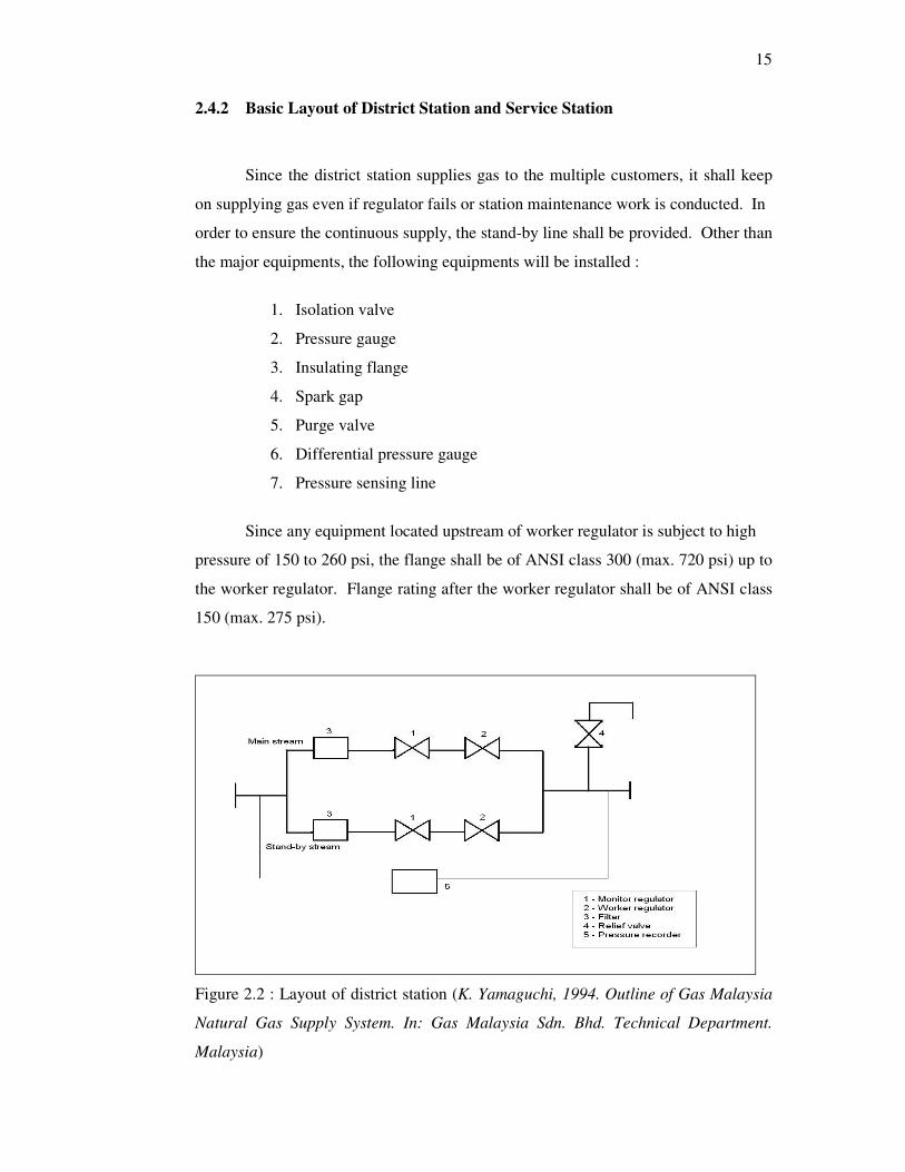
2.4.2 Basic Layout of District Station and Service Station
Since the district station supplies gas to the multiple customers, it shall keep
on supplying gas even if regulator fails or station maintenance work is conducted. In
order to ensure the continuous supply, the stand-by line shall be provided. Other than
the major equipments, the following equipments will be installed :
1. Isolation valve
2. Pressure gauge
3. Insulating flange
4. Spark gap
5. Purge valve
6. Differential pressure gauge
7. Pressure sensing line
Since any equipment located upstream of worker regulator is subject to high
pressure of 150 to 260 psi, the flange shall be of ANSI class 300 (max. 720 psi) up to
the worker regulator. Flange rating after the worker regulator shall be of ANSI class
150 (max. 275 psi).
Figure 2.2 : Layout of district station (K. Yamaguchi, 1994. Outline of Gas Malaysia
Natural Gas Supply System. In: Gas Malaysia Sdn. Bhd. Technical Department.
Malaysia)

16
Basically the single stream service station will be installed because of
economical reason. However the gas supply will be interrupted or controlled roughly
by the manual valve operation when the worker fails or the station maintenance work
is conducted. Monitor regulator may be installed to replace slam shut valve when the
continuous gas supply is taken into consideration seriously. Other than major
equipments, the following equipments will be installed :
1. Isolation valve
2. Pressure gauge
3. Insulating flange
4. Spark gap
5. Volume corrector (if required)
6. Purge valve
7. Differential pressure gauge
8. Pressure sensing line
9. Straightening vane
Figure 2.3 : Layout of service station (K. Yamaguchi, 1994. Outline of Gas Malaysia
Natural Gas Supply System. In: Gas Malaysia Sdn. Bhd. Technical Department.
Malaysia)

17
2.4.3 Distribution of Liquefied Petroleum Gas
For liquefied petroleum gas distribution, it is not same as natural gas in term
of continuity of gas supply and the distribution of the gas. For liquefied petroleum
gas, it is stored inside a tank before the gas is distributed to the customer via a
pipeline. The allowable operating pressure for the bulk tank is around 80-100 psig
while for the piping of the gas starting from the tank to the customer is 5 psig for
residence and commercial and 20 psig for industrial.[2]
In Figure 2.3, it is shows that there are two types of LPG distribution system
which is type one is the gas from LPG tank will distributed to customer via pipeline
which is controlled by the regulator at regulator station. For the second type, the gas
need to vaporize first before flow to the regulator station and then will flow to the oil
separator which is in this stage, the oil will separated in vapor form and not in liquid
form before distribute to the customers.
Figure 2.4 : Layout of LPG distribution outline (Ir. Chong Kim Tham, 2005. Safety
Aspect of Natural Gas Distribution System. Malaysia. Gas Malaysia Sdn. Bhd.)
18
2.4.4 Design Of Pipeline
Cornell et. al. (1959) mentioned that before the pipeline project can be
done/establish , there are some steps that must be done. These steps is a simple
guidelines which already be done from the previous engineer/contractor that dealt
with pipeline project. Steps in a pipeline project are :
1. Market survey – immediate and prospects for growth.
2. Pipe size and working pressure.
3. Pipe specifications.
4. Map of tentative route.
5. Bill of materials.
6. Total cost estimate.
7. Certificate of convenience and necessity.
8. Right of way.
9. Construction survey.
10. Construction contract.
11. Construction.
12. Testing.
13. Putting in service.
For routing process, some criteria need to consider earlier before any project
will begin. It is consists of :
1. Maps
This is where the area between supply & delivery should be examined and
determine either the route is possible or not to choose so that the selected route is free
from any constraints and other problem that will arise.

19
2. Survey
After the maps is determined and analyzed and the selected route has been
drafted, then the visual survey will undergo to examined and to get the analysis for
the selected route which is to avoid any obstacles that may face such as :
1. Congested underground plant
2. Unstable structures
3. Natural ground level altered
4. Subsidence or side slip
5. Running ground or gravel ; traffic loaded routes
6. Aggressive soil
7. Close to cathodic protection systems or stray d.c earth current.
8. Direct underneath overhead cables
9. Internal piping, through circulating duct, chimney, gas vent, ventilating
duct, enclosed staircase, elevator shaft, electricity, facility room,
excessive vibration area, corrosive areas, concrete slab, soil partition.
Piping systems and supports must be designed for strength and structural
integrity in addition to meeting flow, pressure drop, and pump power requirements.
Consideration must be given to stresses created by the following :
1. Internal pressure.
2. Static forces due to weight of the piping and the fluid.
3. Dynamic forces created by moving fluids inside the pipe.
4. External loads caused by seismic activity, temperature changes,
installation procedures, or other application-specific conditions.
The American Society of Mechanical Engineers (ASME), the National Fire
Protection Association (NFPA), and others develop standards for such
considerations.

20
2.5 Standards And Codes
In this project, reference are made based on the existing codes and standards
such as ASME B31.8, MS 830, MS 930, NFPA, and ASTM. Therefore, some words
are already been extracted and summarized in order to make it in form of article
review. For distribution design, it is majorly referred to Malaysia Standard as this
standard has been used formerly in gas distribution project in Malaysia. For further
review, other standard will be used such as ASME B31.8 and NFPA.
2.5.1 Design, Installation, And Testing
In this code, it intended to be adequate for public safety under all conditions
that will be encountered in the gas industry. Conditions that may cause additional
stress in any part of a line or its appurtenances shall be provided for using good
engineering practice. [3]
2.5.2 Class Locations
The standards classify populated areas by the number of people who live,
work, attend school, or otherwise gather in the area. The standard defines a class
location unit as an area that extends 220 yards on either side of the center line of any
continuous one-mile length of pipeline.
Class location units are used in a number of ways to define requirements for
building, testing, and inspecting the gas system. In general, the more heavily
populated the unit, the stricter the pressure testing requirements.

21
Table 2.3 : Class location definitions in constructing of gas pipeline [1]
Class Location Definition
Class 1 Location Any class location unit that has 10 or fewer buildings
intended for human occupancy.
Class 2 Location Any class location unit that has more than 10 but fewer
than 46 buildings intended for human occupancy.
Class 3 Location 1) Any class location unit that has 46 or more buildings
intended for human occupancy ; or
2) Any area where the pipeline lies within 100 yards of
either :
* A building , or
* A small, well-defined outside occupied by 20 or more
persons 5 days a week for 10 weeks in any 12 months
period.
Class 4 Location Any class location unit where the building are mostly 4 or
more stories above ground.
2.5.3 Protection of Pipelines and Mains From Hazards
For natural hazards such as washouts, floods, unstable soil, landslides or other
conditions that may cause serious movements of the pipelines, reasonable precautions
shall be taken to protect the pipeline such as :
1. increasing the wall thickness
2. constructing revetments
3. preventing erosion
4. installing anchors
If the pipelines and mains cross areas that are normally under water (i.e.
lakes, bays, or swamps), sufficient weight or anchorage shall be applied to the
line to prevent from floatation. [3]
22
2.5.4 Clearance Between Pipelines or Mains and Other Underground
Structures
If there any buried pipeline and any other underground structure not used in
conjunction with the pipeline, there shall be at least 6 in. of clearance between them.
If there any buried gas main, there shall be at least 2 in. of clearance between it. But,
if such clearance cannot be attained, precautions to protect the main shall be taken
such as installation of insulating material or casing. [3]
2.5.5 Allowable Maximum Operating Pressure
The coverage of piping systems is limited to the maximum operating pressure
of 420 kPa (gauge) [60 psig] except that piping systems for gas-air mixture within the
flammable range are limited to maximum pressure of 70 kPa (gauge) [10 psig].
Coverage of piping systems includes design, materials, components,
fabrication, assembly, installation, testing, inspection, operation and
maintenance. Coverage of gas utilization equipment and related accessories includes
installation, combustion and ventilation air, and venting. [1]
2.5.6 Maximum Design Operating Pressure
In MS 930 (1986), it is stated that the maximum design operating pressure for
piping systems located inside buildings shall not exceed 5 psig unless approved by
the authority having jurisdiction and one or more of the following conditions are met:
1. The piping system is welded.
2. The piping is located in a ventilated chase or otherwise enclosed for
protection against accidental gas accumulation.

23
3. The piping is located inside buildings or separate areas of buildings used
exclusively for :
a) industrial processing or heating.
b) research
c) warehouse
d) boiler or mechanical equipment rooms
2.5.7 Piping Underground
In ASME B31.8 (2003), it is mentioned that the underground gas piping
should be installed with enough clearance from any other underground structure to
avoid contact therewith, to allow proper maintenance and to protect against damage
that might result from proximity to other structures. In addition, underground plastic
piping shall be installed with sufficient clearance, or shall be insulated, from any
source of heat so as to prevent the heat from impairing the serviceability of the pipe.
Where soil conditions are unstable and setting of piping or foundation walls or
heavy vehicular traffic may occur, adequate measures shall be provided to prevent
excessive stressing of the piping. Piping shall be buried a sufficient depth or covered
in a manner so as to protect the piping from physical damage. Consideration should
be given to protecting the piping from physical damage when it passes through flower
beds, shrub beds and other such cultivated areas.
Underground piping systems should be installed with at least 450 mm of
cover. The cover may be reduced to 300 mm if external damage to the pipe is not
likely to result. If a minimum of 300 mm of cover cannot be maintained, the pipe
shall be installed in conduit or bridged.

24
The trench shall be graded so that the pipe has a firm, substantially continuous
bearing on the bottom of the trench. The backfilling shall be exercised to see that the
pipe is not floated from its firm bearing on the trench bottom and in manner to
provide firm support under the pipe.
2.5.8 Piping Underground Beneath Building and Protection Against Corrosion
When the installation of gas piping underground beneath buildings is
unavoidable, the piping shall be encased in an approved conduit designed withstand
the superimposed loads. The condition shall extend into a normally usable and
accessible portion of the building and at the portion where the conduit terminates in
the building.
The space between the conduit and the gas piping shall be sealed to prevent
the possible entrance of any gas leakage. If the end sealing is of a type that will retain
the full pressure of the pipe, the conduit shall be designed for the same pressure as the
pipe. [3]
Gas piping in contact with earth, or other material which may corrode the
piping, shall be protected against corrosion in an approved manner. When dissimilar
metals are joined underground, an insulating coupling or fitting shall be used. Piping
shall not be laid in contact with cinders.
Uncoated threaded or socket welded joint shall not be used in piping in
contact with soil or where internal or external crevice corrosion may occur. [3]