Embed Size (px)
Citation preview

HAL Id: hal-01580754https://hal.archives-ouvertes.fr/hal-01580754
Submitted on 2 Sep 2017
HAL is a multi-disciplinary open accessarchive for the deposit and dissemination of sci-entific research documents, whether they are pub-lished or not. The documents may come fromteaching and research institutions in France orabroad, or from public or private research centers.
L’archive ouverte pluridisciplinaire HAL, estdestinée au dépôt et à la diffusion de documentsscientifiques de niveau recherche, publiés ou non,émanant des établissements d’enseignement et derecherche français ou étrangers, des laboratoirespublics ou privés.
Distributed under a Creative Commons Attribution| 4.0 International License
Hysteresis behaviour modelling of woven compositeusing a collaborative elastoplastic damage model with
fractional derivativesAlina Krasnobrizha, Patrick Rozycki, Laurent Gornet, Pascal Cosson
To cite this version:Alina Krasnobrizha, Patrick Rozycki, Laurent Gornet, Pascal Cosson. Hysteresis behaviour modellingof woven composite using a collaborative elastoplastic damage model with fractional derivatives. Com-posite Structures, Elsevier, 2016, 158, pp.101-111. �10.1016/j.compstruct.2016.09.016�. �hal-01580754�

Hysteresis behaviour modelling of woven composite using a
collaborative elastoplastic damage model with fractional derivatives
to repmposital behacomputivative-rate eis presated fordissipat
2
Alina Krasnobrizha, Patrick Rozycki, Laurent Gornet, Pascal CossonLUNAM Université, Ecole Centrale de Nantes, Institut de Recherche en Génie Civil et Mécanique (GeM), UMR CNRS 6183, BP 92101, 44321 Nantes Cedex 3, France
The collaborative model is a new toolincluding hysteresis loops for woven comodels. The first one describes a materistrains as well as the in-ply damage areing unloading path using a fractional derthe hysteresis loops. The material strainparameters identification methodologydetailed. The collaborative model is validmatrixes. The precise estimation of the
Keywords:Composite materialBehaviour lawHysteresisFractional derivativeCharacterisation
resent visco-elastoplastic damaged material behavioures under cyclic loading. The model consists of two sub-viour during loading path. The elastic and the in-elasticed. The second part deals with hysteresis modelling dur-approach. Just a few parameters are required to representffect is also taken into account by two sub-models. Theented and the fractional derivative approximations arethe woven composite with thermoset and thermoplasticed energy is possible.
1. Introduction
The extensive use of composite materials in the industrial appli-cations requires a careful examination of their mechanical proper-ties. The material behaviour must be validated experimentally fordifferent types of loadings (static, dynamic, fatigue) dependingon the material application. Then, a behaviour model should bedeveloped to simulate structures’ response as a supportive toolto the experimental method. As the composites are anisotropicheterogeneous materials, complex models are required to ade-quately describe their response. Some works referred by [1–6] isconcerned with the composites behaviour modelling in the mesos-cale. Another option is to use the micromechanics models [7,8].Based on the in-ply damage scenarios at the microscale, a recentwork [8] considers the coupling between the delamination andmicro cracking. These models take into account only the damagepropagation, the material hardening and the in-elastic strains’appearances. Furthermore, the polymer matrix composites havethe viscoelastic behaviour due to the nature of matrix and thisbehaviour is evident in the material’s strain-rate sensibility. Thedependence of a material’s strain rate sensitivity on the viscoelas-tic effects was first taken into account in the works [9–11] for the
unidirectional composites and in the works [12–14] for the wovencomposites.
However, the coupling between the cyclic loading damages andthe viscoelastic effects has not been considered in the classicaldamage modelling [1–14]. It must be highlighted that the damagepropagation is strongly linked with the material energy dissipationand, thus, with the hysteresis loops appearance. Thus, the precisemodelling of hysteresis loops is needed. Therefore, in this paperwe propose a collaborative model based on a fractional derivativeapproach.
A fractional derivative theory is a promising technique todescribe the history-dependent phenomena like viscoelasticity. Asignificant number of fractional viscoelastic models have beendeveloped and successfully applied tomodel amechanical responseof natural structures and modern heterogenic materials such aselastomers and polymers [15–17]. The classical rheological modelsare rewritten in terms of fractional derivative like the Kelvin-Voigt[18,19], Maxwell [20–22] and Zener [23,24] fractional models thatallows to obtain creep and relaxation functions adapted for thepolymers’ response. Rabotnov has developed a hereditary theorywhere he had introduced a generalized fractional rheological modeland a new class of hereditary functions in his works [25–27]. TheRabotnov’s theory is widely used to describe the behaviour of thepolymers, metals and concrete. Bagley and Torvik established thefractional law in the frequency domain to describe the behaviourof polymers and elastomers [28]. The link betweenmolecular struc-ture of polymers and fractional derivative law is given in the works[29–31] for the different types of polymers. These relations were

obtained by using the Rouse molecular theory [32]. The hysteresisloops’ appearance is another viscoelastic effect which can beobserved in the viscoelastic materials response and then, it can betreated using the fractional derivative approach. Caputo hasdescribed the hysteresis loop using the fractional derivatives inthe frequency domain to determine a fatigue limit for a few metals[33]. Mateos [34] proposed a fractional derivative model with a fewmaterial parameters to describe the hysteresis composite beha-viour in the temporal domain. This model also includes strain-rate dependence and can be applied for dynamic loading [35]. Theelastic and the irreversible strains, the damage and the strain rateeffects are taken into account into [34] and [35] but not thematerialhardening. Moreover, these phenomena that are cited are in-separable making it difficult to calculate their individual contribu-tion in the material’s energy dissipation. Hence this paper proposesa collaborative model to describe the complete composite beha-viour during cyclic loading including the representation of the hys-teresis phenomena during the loading-unloading paths. Theproposedmodel is composed of the elastoplastic damage behaviourlaw [3] with possible strain-rate sensitivity [9] and including anewly proposed fractional derivative approach. This model allowsus to distinguish the dissipation due to the material damage, plas-ticity and viscoelasticity.
This paper is organized as follows. In Section 2, the essentialmathematical elements of the fractional calculus are introducedand the collaborative model for woven composite materials is pro-posed in the Section 3. The parameter identification procedure isdeveloped in the Section 4 and the validation of the collaborativemodel is demonstrated in the Section 5. The Section 6 concludes thispaper and notes the various engineering application of this model.
2. Introduction in fractional calculus
The advent of advanced materials requires new mathematicalmethods to describe their behaviours. One of the ways is toincrease the number of parameters in the existing constitutivelaws. This leads to sophisticated models with a significant numberof parameters which sometimes require complex identificationprocedures. On the other hand, new methods may be introducedas the fractional derivative theory.
Fractional operators are an extension of the order of the inte-grals and derivatives to the fractional order. By their definition,the fractional operators take into account the past loading historyand are suitable to describe the viscoelastic phenomena. The solu-tion of fractional differential equations is expressed by the frac-tional functions [36,37] whereas the solution of ordinarydifferential equations is an exponential basis. Therefore, the frac-tional behaviour laws are widely used to describe behaviour ofheterogeneous materials and fractal structures such as polymers,alloys and geological strata [27,38,39].
There are a few definitions of the fractional integrals andderivatives which are equivalent for most of the functions but theydo not always lead to the same results. In this work the classicalRiemann and Liouville definition (6) [40,41] is used. To deduce thisdefinition, the formula of nth repeated integral of the continuousfunction f ðxÞ (Cauchy’s formula) is used:Z x
adx
Z x
adx . . .
Z x
af ðxÞdx ¼ 1
ðn� 1Þ!Z x
aðx� tÞn�1f ðtÞdt; n 2 N ð1Þ
To generalize the Eq. (1), the natural number n is replaced by areal positive number a. It is known that the extension of the facto-rial function to real and complex numbers is the gamma functionCðzÞ defined by:
CðzÞ ¼Z þ1
0e�xxz�1dx; z 2 R�
þ ð2Þ
3
The gamma function CðzÞ satisfies the following recurrencerelation:
Cðzþ 1Þ ¼ zCðzÞ; z 2 R�þ ð3Þ
The fractional Riemann-Liouville integral of order a (4) isobtained from the generalized form of the Eq. (1) by using theproperty of the gamma function (3)
ðIaa f ÞRLðxÞ¼def 1
CðaÞZ x
a
f ðtÞðx� tÞ1�a
dt; a > 0 ð4Þ
where ðIaa f ÞRLðxÞ is the fractional integral of order a of the functionf ðxÞ.
The fractional derivative is an inverse operator to the fractionalintegral. Let us consider a which is a positive real number and nwhich is an integer that satisfies the inequality n� 1 < a < n.The fractional derivative of order a is defined as the fractional inte-gral of order n� a derived n times. For example, if a belongs to theopen interval ð0;1Þ, the fractional derivative of order a of the func-tion f ðxÞ is the fractional integral of order 1� a derived one time:
ðDaa f ÞRLðxÞ¼
def ddx
ðI1�aa f ÞRLðxÞ ð5Þ
The alternative form of the previous expression is:
ðDaa f ÞRLðxÞ¼
def 1Cð1� aÞ
ddx
Z x
a
f ðtÞðx� tÞa dt; 0 < a < 1 ð6Þ
where ðDaa f ÞRLðxÞ is the fractional derivative of order a in the sense
of Riemann- Liouville.
2.1. Numerical evaluation of fractional derivatives
In order to implement the fractional derivatives in a numericalcode, different algorithms exist. The L1-approximation [42] of theRiemann-Liouville fractional derivative (6) ðDa
0 f ðxÞÞL1 has a follow-ing form:
ðDa0 f ðxÞÞL1 ¼ 1
Cð1�aÞf ð0Þxa þ
þ 1Cð2�aÞ
XN�1
j¼0
f ðx�xjþ1Þ�f ðx�xjÞDx ½x1�ajþ1 � x1�aj �
ð7Þ
where Dx is a step interval, N is a number of interval points and C isthe gamma function defined by (2).
The Riemann-Liouville fractional integral (4) can be rewritten inthe alternative forms [43]:
ðIa0 f ðxÞÞM1 ¼ xa
Cðaþ 1ÞZ 1
0f ðxð1� v1
aÞÞdv ð8Þ
ðIa0 f ðxÞÞM2 ¼ 2xa
Cðaþ 1ÞZ 1
0f ðxð1� v2
aÞÞdv ð9Þ
The formulas (8) and (9) can be easily implemented in thenumerical code if an analytical expression of the function f ðxÞ isknown.
According to the expression (6), the fractional derivative is thefirst derivative of the M1 (8) or M2 (9) integrals. The M1 and M2fractional derivate approximations are calculated by a central dif-ference scheme:
ðDa0 f ðxÞÞM1 ¼ ðI1�a0 f ðxþ DxÞÞM1 � ðI1�a0 f ðx� DxÞÞM1
2Dxð10Þ
ðDa0 f ðxÞÞM2 ¼ ðI1�a0 f ðxþ DxÞÞM2 � ðI1�a0 f ðx� DxÞÞM2
2Dxð11Þ
In order to estimate the numerical accuracy of the proposedapproximations, the fractional derivatives of the linear functionf ðxÞ ¼ x are computed by the methods (7), (10) and (11) and com-pared with the analytical results (12) [36].

Fig. 2. Relative errors comparison for the fractional derivatives of the linearfunction.
Table 1Total relative errors comparison for the linear function f ðxÞ ¼ x.
dM1ð%Þ dM2ð%Þ dL1ð%Þ0.2611 0.2612 5.712
Fig. 3. Specimen geometry for ½0�8 laminate.
Fig. 4. Specimen geometry for ½45�8 laminate.
ðDa0 f ÞRLðxÞ ¼
1Cð2� aÞ x
1�a ð12Þ
The order of fractional derivatives is set a ¼ 0:3. The computa-tional interval x 2 ð0;1Þ is discretized by N ¼ 20 points. The resultsare illustrated in the Fig. 1.
Accuracy of the proposed methods is estimated by using the rel-ative error drelativei (13) and the total error d (14) functions.
drelativei ¼ jDaf ðxiÞanalyt � Daf ðxiÞapproxjDaf ðxiÞanalyt
100% ð13Þ
d ¼ 1N
XNi¼1
drelativei ð14Þ
where Daf ðxiÞanalyt is the fractional derivative computed analytically
by the Eq. (12), Daf ðxiÞapprox corresponds to the L1, M1 or M2 approx-imations defined by the Eqs. (7), (10), (11) respectively.
The integrals (8) and (9) are computed using the Gaussianquadrature. The computed interval ð0;1Þ is divided in ten sub-intervals and five gauss-points are used in each sub-interval.
The results are presented in the Fig. 2 and in the Table 1. Thebiggest error is observed near the zero point. The total relativeerrors of M1 and M2 algorithms are less than 1%. The M1-methodis the most accurate and is used in further calculations.
3. Theoretical model for composite ply
The material which is used in this work is a carbon woven fibreepoxy matrix composite. The traction cyclic tests have been carriedout on an Instron 3369 machine with a strain rate of 5 mm/min intwo different orthotropic directions: fibre and shear directions. Thespecimens’ geometry and their dimensions for [0]8 and [45]8woven laminates are shown in the Figs. 3 and 4 respectively. Thenominal thickness of the samples is 1.8 mm.
The experimental result of the tensile cyclic test for the wovencarbon/epoxy composite is illustrated in the Figs. 5 and 6. Sub-scripts 1 and 2 represent the warp and the weft directions, respec-tively. The composite is considered to be perfectly balanced andthus the longitudinal and transverse behaviours are consideredto be equivalent. Typically, the experimental tests show an elasticbrittle response in longitudinal (transverse) direction (Fig. 5). How-ever, shear behaviour has a non-linear character. The irreversiblestrains, the in-ply damage (which is observed from a regulardecrease of shear modulus) and the hysteresis loops are presentedin the stress-strain curve (Fig. 6).
Fig. 1. Different fractional derivative numerical approximations for a functionf ðxÞ ¼ x.
Fig. 5. Longitudinal traction curve for the carbon/epoxy composite.
4
The collaborative model is developed to represent the elasto-plastic damaged material behaviour as well as the hysteresis loopsfor woven composites under cyclic loading. The model is based onthe collaboration of two sub-models. The first one deals with acomposite behaviour during loading path. The elastic and thein-elastic strains are computed as well as the in-ply damage. The

Fig. 6. Shear stress-strain curve for the carbon/epoxy composite.
second sub-model involves the fractional derivative approach torepresent the hysteresis loops during unloading path. The mesos-cale model is developed under a state of plane stress. The constitu-tive equations are deduced within the framework of irreversiblethermodynamics processes using the local state method.
3.1. Thermodynamic aspects
Within the framework of irreversible thermodynamics, a Helm-holtz potential qw is chosen as a function of internal variables:
qw ¼ qwðee;di;pÞ ð15Þwhere ee, di, p are internal variables associated with elastic strain,damage in the orthotropic directions and cumulated plasticityrespectively.
3.2. Damage modelling
Under the given loading, the damage appears in the elementaryply. It leads to the degradation of the mechanical properties andthen to the material failure. The continuum damage mechanicstheory is used to describe the degradation of elementary ply[44]. Using the effective stresses notation [45], the degradedstiffness matrix C is introduced as follows:
C ¼ð1� d11ÞC0
11 m021C011 0
m012C022 ð1� d22ÞC0
22 0
0 0 ð1� d12ÞG012
0BB@
1CCA
with
C011 ¼ E011
1�m012m021and C0
22 ¼ E0221�m012m021
m021E011 ¼ m012E
022
8>><>>:
ð16Þ
where m012 and m021 are the Poisson’s ratios, E011 and E0
22 are longitudi-
nal and transverse Young’s moduli and G012 is a shear modulus.
The damage internal variables ðd11; d22; d12Þ represent the mate-rial degradation in orthotropic directions. These parameters are setbetween 0 and 1:
� When the material is not degraded: dij ¼ 0; fi; j ¼ 1;2g� If there is a ‘‘complete” damage: dij ¼ 1; fi; j ¼ 1;2g.
The constitutive equations are deduced using the second princi-pal of thermodynamics. The elastic strain energy of the damaged
material Wde (equivalent to the Helmholtz potential qw) has a
following form:
5
Wde ¼
12fC0
11ð1� d11Þðee11Þ2 þ C022ð1� d22Þðee22Þ2
þ 2m021C011e
e11e
e22 þ G0
12ð1� d12Þð2ee12Þ2g ð17Þwhere ee11; ee22 and ee12 are the component of the elastic strain vector.
The stress-strain relation is:
r¼ @Wde
@ee)
r11
r22ffiffiffi2
pr12
0B@
1CA¼
ð1�d11ÞC011 m021C
011 0
m012C022 ð1�d22ÞC0
22 0
0 0 2ð1�d12ÞG012
0BB@
1CCA
ee11ee22ffiffiffi2
pee12
0B@
1CA
ð18Þwhere r is the stress vector.
The thermodynamic forces associated with internal variables dij
are defined as following:
Yij ¼ � @Wde
@dij)
Y11 ¼ 12C011ðee11Þ2; Y22 ¼ 1
2C022ðee22Þ2; Y12 ¼ 1
2G0
12ð2ee12Þ2ð19Þ
where Y11; Y22 and Y12 are thermodynamic forces associated withdamage internal variables d11;d22 and d12.
The associated thermodynamic forces characterize the damagepropagation. The state of damage can only grow [1,3,46] and there-fore, the threshold of undamaged zone �Yij is defined as a maximalthermodynamic force for all previous time ðsÞ up to the currenttime ðtÞ [12]:
Y�ij ¼ sups6tðYijðtÞÞ; fi; j ¼ 1;2g ð20ÞThe coupling between the internal damage variables and the
associated thermodynamic forces is determined by the experimen-tal data fitting and the functions given below are frequently usedfor this:
Linear law
dij ¼
ffiffiffiffiffiffiYij
q�
ffiffiffiffiffiffiY0
ij
qffiffiffiffiffiYc
p if dij < 1 and Yij < YRij; otherwise dij ¼ 1 ð21Þ
Heaviside function H (This function is used to describe elasticbrittle behaviour)
dij ¼ HffiffiffiffiffiffiYij
q�
ffiffiffiffiffiffiYR
ij
q� �if dij < 1 and Yij < YR
ij; otherwise dij ¼ 1
ð22Þwhere Y0
ij is initial damage thresholds and YRij is failure-damage
thresholds in the orthotropic directions. The constants in these lawsare the material parameters.
The Eqs. (21) and (22) are not always able to adequately repre-sent the damage propagation especially in the composite materialwith thermoplastic matrix. Thus, the polynomial law is proposed[47] to increase the performance of the elastoplastic damagemodel:
dij ¼XNn¼1
anij
ffiffiffiffiffiffiYij
q�
ffiffiffiffiffiffiY0
ij
q� �n
if dij < 1 and Yij < YRij; otherwise dij ¼ 1
ð23Þ
3.3. Plasticity modelling and damage-plasticity coupling
The experimental data shows the irreversible strains appearingmainly in shear [6,9,12,13]. Thus, plastic flow is considered to beblocked in fibre directions:

ep11 ¼ ep22 ¼ 0; ep12–0 ð24Þwhere ep11; e
p22 and ep12 are the components of the plastic strain.
The damage and plasticity coupling is made using the effectivestress notation ~r12 (25).
~r12 ¼ r12
ð1� d12Þ ð25Þ
The isotropic strain hardening is assumed. The elastic domain isdefined by the yield function f :
f ¼ j~r12j � RðpÞ � R0 ð26Þwhere R0 is a yield stress and the function RðpÞ is a material charac-teristic function of the cumulative plastic strain p. Generally, thehardening function RðpÞ is approximated by a power law:
R ¼ bpk with p ¼Z ep12
0ð1� d12Þdep12 ð27Þ
where b and k are material parameters identified from the experi-mental data.
The material parameter identification is detailed in the nextsections. The resulting stress-strain shear curve is obtained bythe elastoplastic damage model [3] for the carbon/epoxy wovencomposite (Fig. 7). The simulation results are in a good agreementwith the experimental data. However, the hysteresis loops cannotbe reproduced by this model.
3.4. Fractional derivative model to represent hysteresis loops
The woven composites have a hysteresis behaviour for certainloading types such as a cyclic shear test. The reason of this is thatthe matrix is subjected a bigger part of the shear load and as aresult, the viscoelastic response of the polymer matrix can beobserved as well as the gradual development of microscopic dam-age in the matrix or along matrix-fibre interface. This leads to theappearance of hysteresis loops which is associated with materialenergy dissipation. Since we are dealing with a viscoelastic phe-nomenon, the loading history has to be taken into account. Thatis why the fractional derivatives are introduced in the behaviourlaw to provide the material history dependence.
To deduce a behaviour law during an unloading path let us con-sider one hysteresis loop. According to the elastoplastic damagemodel, the plastic strain stays constant and the elastic strain is alinear function of time. However, a non-linearity in strain isobserved in the experimental curve during the unloading/reload-ing path (Fig. 8).
Commonly, an additional viscoelastic strain vector eve is intro-duced to take into account the observed non-linearity. In this case,
Fig. 7. Comparison of experimental and simulated behaviour by elastoplasticdamage model in shear for the carbon/epoxy composite.
6
the total strain et12 is a sum of three strains: elastic ee12, plastic ep12
and viscoelastic eve12:
et12 ¼ ee12 þ ep12 þ eve12 ð28ÞGenerally, this approach leads to the complex models with a
large number of parameters.An alternative approach is proposed in this work. In order to
model the viscoelastic effect, the fractional derivatives are intro-duced in the governing law. The total strain within the hysteresis
loop eloop12 is defined as following:
eloop12 ¼ Aþ 2BDaee12ðtÞ ð29Þwhere ee12 is the elastic strain determined by the elastoplastic dam-age model, Da is the Riemann-Liouville fractional derivative (6) andA, B and a are the fractional model parameters.
As the plastic flow stays constant, the stress is expressed by theelastic law:
r12ðtÞ ¼ G012ð1� d12Þeloop12 ðtÞ ð30Þ
By substitution the Eq. (29) in the Eq. (30), the constitutive law is:
r12ðtÞ ¼ G012ð1� d12ÞAþ 2G1
12Daee12ðtÞ ð31Þ
with G112 ¼ G0
12ð1� d12ÞB.The Eq. (31) is a non-standard form of Kelvin-Voight fractional
model. The parameters A;B and a is considered to be the functionsof damage d12 and consequently of the elastic strain ee12 taking intoaccount that shear damage is a function of the shear elastic strain:d12 ¼ d12ðee12Þ. In order to signify meanings of the fractional param-eters, the influence of each term in the Eq. (31) is considered.
� The fractional derivative of the elastic strain Daee12ðtÞ provides astrain non-linearity. Hence, the hysteresis loop appears (Fig. 9).The fractional order a adjusts the loop size. The growth of aleads to the increasing of loop area and consequently the dissi-pation of viscoelastic energy increases.
� The factor G112 governs the slope of the loop (Fig. 10). The damage
level is adjusted in respect to the elastoplastic damage model.� The term G0
12ð1� d12ÞA is a connecting stress that links two sub-models: the fractional and the elastoplastic damage models(Fig. 11). Thus the position of the loop is adjusted and the stressbecomes a continuous function.
3.5. Coupling of two sub-models
In this part, the coupling between two sub-models isconsidered.
Fig. 8. Total strain composition.
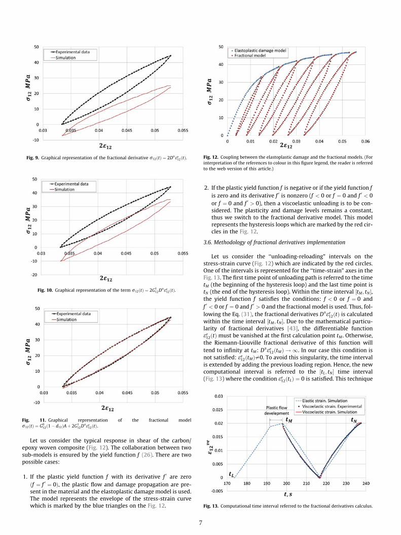
Fig. 12. Coupling between the elastoplastic damage and the fractional models. (Forinterpretation of the references to colour in this figure legend, the reader is referredto the web version of this article.)
Fig. 13. Computational time interval referred to the fractional derivatives calculus.
Fig. 11. Graphical representation of the fractional modelr12ðtÞ ¼ G0
12ð1� d12ÞAþ 2G112D
aee12ðtÞ.
Fig. 9. Graphical representation of the fractional derivative r12ðtÞ ¼ 2Daee12ðtÞ.
Fig. 10. Graphical representation of the term r12ðtÞ ¼ 2G112D
aee12ðtÞ.
Let us consider the typical response in shear of the carbon/epoxy woven composite (Fig. 12). The collaboration between twosub-models is ensured by the yield function f (26). There are twopossible cases:
1. If the plastic yield function f with its derivative f 0 are zeroðf ¼ f 0 ¼ 0Þ, the plastic flow and damage propagation are pre-sent in the material and the elastoplastic damage model is used.The model represents the envelope of the stress-strain curvewhich is marked by the blue triangles on the Fig. 12.
7
2. If the plastic yield function f is negative or if the yield function fis zero and its derivative f 0 is nonzero (f < 0 or f ¼ 0 and f 0 < 0or f ¼ 0 and f 0 > 0), then a viscoelastic unloading is to be con-sidered. The plasticity and damage levels remains a constant,thus we switch to the fractional derivative model. This modelrepresents the hysteresis loops which are marked by the red cir-cles in the Fig. 12.
3.6. Methodology of fractional derivatives implementation
Let us consider the ‘‘unloading-reloading” intervals on thestress-strain curve (Fig. 12) which are indicated by the red circles.One of the intervals is represented for the ‘‘time-strain” axes in theFig. 13. The first time point of unloading path is referred to the timetM (the beginning of the hysteresis loop) and the last time point istN (the end of the hysteresis loop). Within the time interval ½tM; tN�,the yield function f satisfies the conditions: f < 0 or f ¼ 0 andf 0 < 0 or f ¼ 0 and f 0 > 0 and the fractional model is used. Thus, fol-lowing the Eq. (31), the fractional derivatives Daee12ðtÞ is calculatedwithin the time interval ½tM; tN�. Due to the mathematical particu-larity of fractional derivatives [43], the differentiable functionee12ðtÞ must be vanished at the first calculation point tM . Otherwise,the Riemann-Liouville fractional derivative of this function willtend to infinity at tM: D
aee12ðtMÞ ! 1. In our case this condition isnot satisfied: ee12ðtMÞ–0. To avoid this singularity, the time intervalis extended by adding the previous loading region. Hence, the newcomputational interval is referred to the ½tL; tN� time interval(Fig. 13) where the condition ee12ðtLÞ ¼ 0 is satisfied. This technique

Fig. 14. Function of the longitudinal damage evaluation for the carbon/epoxycomposite.
allows to define the fractional derivative value at the first point ofthe hysteresis loop Daee12ðtMÞ. In other words, to reproduce the hys-teresis loop on the ‘‘unloading-reloading” time interval ½tM; tN�, thefractional derivatives are computed on the ‘‘loading-unloading-reloading” interval ½tL; tN� to avoid the mathematical problems.
The fractional operators are approximated by using the M1-method expressed by the formulas (8), (10) which can be rewrittenas following:
ðI1�a0 ee12ðtÞÞM1 ¼ t1�a
Cð2� aÞZ 1
0ee12ðtð1� v 1
1�aÞÞdv ð32Þ
ðDa0e
e12ðtÞÞM1 ¼ ðI1�a0 ee12ðt þ DtÞM1 � ðI1�a0 ee12ðt � DtÞÞM1
2Dtð33Þ
To use the formulas (32) and (33), the analytical expression ofthe ee12ðtÞ function has to be reconstructed by using the piecewisefunction.
4. Parameters identification
In the following sections the identification procedure for themodel parameters is described using the experimental data forthe carbon/epoxy woven composite (Figs. 5 and 6). The in-ply dam-age, the isotropic strain hardening and the hysteresis loops mod-elling are taken into consideration.
4.1. Materials characterization in fibres directions
The ½0�=90
� �8 tensile test (Fig. 5) is used to identify the longitu-dinal (or transverse) material behaviour. As the woven fabrics havecommonly a brittle linear response the in fibre directions, the elas-tic parameters such as elastic modulus E0
11ð22Þ, Poisson’s ratio m012ð21Þand rupture stress rR
11ð22Þ are easily identified and presented in theTable 2.
4.1.1. Damage identification in fibre directionsDue to the brittle elastic behaviour, the material failure appears
instantly. The Heaviside step function (22) is used to describe thedamage propagation. The initial damage threshold coincides withthe failure threshold: Y0
11ð22Þ ¼ YR11ð22Þ. Damage parameters are pro-
vided in the Table 3. The damage propagation is illustrated in theFig. 14.
4.2. Materials characterization in shear
The material parameters are identified from the shear experi-mental curve for thermoset composite (Fig. 6). The shear undam-
Table 3Longitudinal (or transverse) damageparameters for the carbon/epoxycomposite.
Parameter Carbon/epoxyffiffiffiffiffiffiffiffiY011
q¼
ffiffiffiffiffiffiffiffiYR11
q2 MPa1=2
Table 2Longitudinal (or transverse)identification of the carbon/epoxy composite.
Parameter Value
E011 ¼ E022 57.3 GPa
m012 ¼ m021 0.07
rR11 ¼ rR
22687 MPa
8
aged modulus G012 and the yield stress R0 are identified from the
linear regression of the elastic part in the experimental stress-strain curve. The failure stress rR
12 corresponds to the maximumreached stress during the test. The elastic parameters in shearare summarized in the Table 4.
4.2.1. Damage and plastic strain evaluation in shearTypical cyclic shear tests show a reduction in the material stiff-
ness. To model the material degradation, the damage variable d12 is
linked with the associated thermodynamic forceffiffiffiffiffiffiffiffiY12
p. The dam-
age level is measured by the shear modulus reduction:
d12 ¼ 1� Gi12
G012
ð34Þ
where Gi12 is a degraded shear modulus.
Using the experimental data we state that damage grows lin-early (Fig. 15) in the carbon/epoxy composite in accordance with
the Eq. (21). In this case, the coefficientffiffiffiffiffiffiffiffiYC
12
qis the speed of dam-
age propagation. The damage parameters are presented in the fol-lowing Table 5.
The cumulative plastic strain p is obtained using the identifieddamage parameters. The strain hardening function RðpÞ is definedby the Eq. (35).
RðpÞ ¼ j~r12j � R0 ð35ÞThe experimental data are fitted using the power law (26). The
approximation is illustrated in the Fig. 16. The identified parame-ters are presented in the Table 6.
4.3. Identification of fractional derivative model parameters
The fractional model (29) parameters A;B and a are identifiedby solving a non-linear optimization problem with constrains.The main constrain is imposed on the fractional derivative ordera: 0 < a < 1. The objective function is defined as a relative error:
Table 4Shear parameters identification forthe carbon/epoxy composite.
Parameter Carbon/epoxy
G012
3.36 GPa
R0 12 MParR12
80 MPa

Fig. 15. Shear damage function for the carbon/epoxy composite.
Fig. 17. Fractional parameter A evaluation with damage for the carbon/epoxycomposite.
Fig. 19. Fractional parameter a evaluation with damage for the carbon/epoxycomposite.
Fig. 18. Fractional parameter B evaluation with damage for the carbon/epoxycomposite.
Fig. 16. Hardening function RðpÞ for the carbon/epoxy composite.
Table 5Shear damage parameters for thecarbon/epoxy composite.
Parameter ValueffiffiffiffiffiffiffiffiYC12
q2.25 MPa1=2
ffiffiffiffiffiffiffiffiY012
q0.15 MPa1=2
ffiffiffiffiffiffiffiffiYR12
q0.8 MPa1=2
Table 6Hardening parameters for the car-bon/epoxy composites.
Parameter Carbon/epoxy
b 266.6 MPak 0.36
d ¼
ffiffiffiffiffiffiffiffiffiffiffiffiffiffiffiffiffiffiffiffiffiffiffiffiffiffiffiffiffiffiffiffiffiffiffiffiffiffiffiffiffiffiffiffiffiffiffiffiXNi¼1
ðeexp12 ðtiÞ � eloop12 ðtiÞÞ2
vuutN
ð36Þ
where eexp12 is an experimental strain determined by the Eq. (37), eloop12
is a shear strain calculated by the fractional model (29) and N is anumber of time-points inside the considered interval.
eexp12 ¼ rexp12
G012ð1� d12Þ
ð37Þ
Three fractional parameters A;B and a are defined for each hys-teresis loops. Their values stay constant within the hysteresis loopbut they are altered in every loop. How it has been mentionedabove, the fractional parameters are the functions of damage.
9
For the carbon/epoxy composite, the fractional parameters arerepresented by linear functions of damage as following:
A ¼ mAd12 þ bA ð38Þ
B ¼ mBd12 þ bB ð39Þ
a ¼ mad12 þ ba ð40ÞThe results are illustrated in the Figs. 17–19. The coefficients of
fittings (38), (39) and (40) are collected in the Table 7.

Table 7Coefficients of fractional parameters fitting for the carbon/epoxy composite.
Parameter Value Parameter Value
mA 0.0189 bA �0.0013mB 1.795 bB 0.8605ma 0.6944 ba �0.0035
5. Results
The carbon/epoxy composite behaviour is represented numeri-cally in fibre directions by the collaborative model using the iden-tified parameters in Fig. 20 and the results of simulation are morethan satisfying since the exact replica of the elastic brittle beha-viour is obtained.
The collaborative model is applied to represent the shear strain-stress curve. The results are in good agreement with the experi-mental data (Fig. 21). Small errors are observed at the first andthe last points of the hysteresis loop. The error at the first pointis related to the mathematical particularity of fractional calculus[43]. The error at the last point is related to the uncertainty ofthe optimal solution. Furthermore, the derivation of the piecewisefunction provides an inaccuracy at the inflection point (the transi-tion from the unloading to the loading path).
The identification of parameters is also made for the thermo-plastic woven composite: carbon/PA66 in shear direction. Thedamage propagation has a non-linear character and is expressedby the third order polynomial law (23). The power law (27) has
Fig. 20. Experimental and numerical behaviour comparison in longitudinal direc-tion for the carbon/epoxy composite.
Fig. 21. Comparison of experimental and simulated behaviour by collaborativemodel in shear for the carbon/epoxy composite.
10
been chosen to fit the hardening function. The symmetrical hys-teresis loops are transformed into the ‘‘bean” shaped loops dueto the fibre reorientation (Fig. 22) and this increases the error indamage identification. To improve the simulation results, the reori-entation of fibre angle has to be taken into account. Due to the non-linear damage law, the fractional parameters A and B also has anon-linear evolution and are approximated by the third order poly-nomial law. The fractional derivative order a has a linear depen-dence on damage but its values rises because of the loop sizeincrements.
The collaborative model is applied to simulate thermoplasticcomposite response. The difference between the experimentaland simulation results is observed towards the end of the resultingstress-strain curve (Fig. 22) when the level of damage is high. Thusthe inexact damage identification provides a supplementary errorin addition to the previously cited fractional calculus problems.The asymmetric hysteresis loops cannot be treated by the collabo-rative model. Despite the unsymmetrical loops form, their areameasures correctly and the amount of dissipated energy can bedetermined precisely.
In conclusion we state that the collaborative model providesmore than satisfactory results for the composite materials with dif-ferent matrixes.
An additional simulation has been made to predict the appear-ance of hysteresis loops during cyclic loading. A six cycles’ experi-mental shear test is replaced by the fictitious eight cycles loadingfor the thermoplastic composite (Fig. 23). The simulation is madewith the previously identified parameters. The results are shown
Fig. 22. Comparison of experimental and simulated behaviour by collaborativemodel in shear for the carbon/PA66 composite.
Fig. 23. Fictitious cyclic loading for the carbon/PA66 composite.
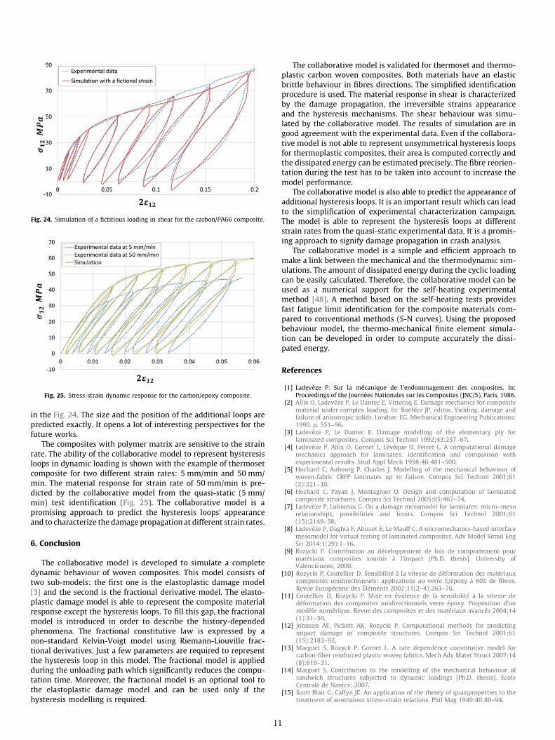
Fig. 24. Simulation of a fictitious loading in shear for the carbon/PA66 composite.
Fig. 25. Stress-strain dynamic response for the carbon/epoxy composite.
in the Fig. 24. The size and the position of the additional loops arepredicted exactly. It opens a lot of interesting perspectives for thefuture works.
The composites with polymer matrix are sensitive to the strainrate. The ability of the collaborative model to represent hysteresisloops in dynamic loading is shown with the example of thermosetcomposite for two different strain rates: 5 mm/min and 50 mm/min. The material response for strain rate of 50 mm/min is pre-dicted by the collaborative model from the quasi-static (5 mm/min) test identification (Fig. 25). The collaborative model is apromising approach to predict the hysteresis loops’ appearanceand to characterize the damage propagation at different strain rates.
6. Conclusion
The collaborative model is developed to simulate a completedynamic behaviour of woven composites. This model consists oftwo sub-models: the first one is the elastoplastic damage model[3] and the second is the fractional derivative model. The elasto-plastic damage model is able to represent the composite materialresponse except the hysteresis loops. To fill this gap, the fractionalmodel is introduced in order to describe the history-dependedphenomena. The fractional constitutive law is expressed by anon-standard Kelvin-Voigt model using Riemann-Liouville frac-tional derivatives. Just a few parameters are required to representthe hysteresis loop in this model. The fractional model is appliedduring the unloading path which significantly reduces the compu-tation time. Moreover, the fractional model is an optional tool tothe elastoplastic damage model and can be used only if thehysteresis modelling is required.
11
The collaborative model is validated for thermoset and thermo-plastic carbon woven composites. Both materials have an elasticbrittle behaviour in fibres directions. The simplified identificationprocedure is used. The material response in shear is characterizedby the damage propagation, the irreversible strains appearanceand the hysteresis mechanisms. The shear behaviour was simu-lated by the collaborative model. The results of simulation are ingood agreement with the experimental data. Even if the collabora-tive model is not able to represent unsymmetrical hysteresis loopsfor thermoplastic composites, their area is computed correctly andthe dissipated energy can be estimated precisely. The fibre reorien-tation during the test has to be taken into account to increase themodel performance.
The collaborative model is also able to predict the appearance ofadditional hysteresis loops. It is an important result which can leadto the simplification of experimental characterization campaign.The model is able to represent the hysteresis loops at differentstrain rates from the quasi-static experimental data. It is a promis-ing approach to signify damage propagation in crash analysis.
The collaborative model is a simple and efficient approach tomake a link between the mechanical and the thermodynamic sim-ulations. The amount of dissipated energy during the cyclic loadingcan be easily calculated. Therefore, the collaborative model can beused as a numerical support for the self-heating experimentalmethod [48]. A method based on the self-heating tests providesfast fatigue limit identification for the composite materials com-pared to conventional methods (S-N curves). Using the proposedbehaviour model, the thermo-mechanical finite element simula-tion can be developed in order to compute accurately the dissi-pated energy.
References
[1] Ladevèze P. Sur la mécanique de l’endommagement des composites. In:Proceedings of the Journées Nationales sur les Composites (JNC/5), Paris, 1986.
[2] Allix O, Ladevèze P, Le Dantec E, Vittecoq E. Damage mechanics for compositematerial under complex loading. In: Boehler JP, editor. Yielding, damage andfailure of anisotropic solids. London: EG, Mechanical Engineering Publications;1990. p. 551–96.
[3] Ladevèze P, Le Dantec E. Damage modelling of the elementary ply forlaminated composites. Compos Sci Technol 1992;43:257–67.
[4] Ladevèze P, Allix O, Gornet L, Lévêque D, Perret L. A computational damagemechanics approach for laminates: identification and comparison withexperimental results. Stud Appl Mech 1998;46:481–500.
[5] Hochard C, Aubourg P, Charles J. Modelling of the mechanical behaviour ofwoven-fabric CRFP laminates up to failure. Compos Sci Technol 2001;61(2):221–30.
[6] Hochard C, Payan J, Montagnier O. Design and computation of laminatedcomposite structures. Compos Sci Technol 2005;65:467–74.
[7] Ladevèze P, Lubineau G. On a damage mesomodel for laminates: micro–mesorelationships, possibilities and limits. Compos Sci Technol 2001;61(15):2149–58.
[8] Ladevèze P, Daghia F, Abisset E, Le Mauff C. A micromechanics-based interfacemesomodel for virtual testing of laminated composites. Adv Model Simul EngSci 2014;1(29):1–16.
[9] Rozycki P. Contribution au développement de lois de comportement pourmatériaux composites soumis à l’impact [Ph.D. thesis]. University ofValenciennes; 2000.
[10] Rozycki P, Coutellier D. Sensibilité à la vitesse de déformation des matériauxcomposites unidirectionnels: applications au verre E/époxy à 60% de fibres.Revue Européenne des Éléments 2002;11(2–4):263–76.
[11] Coutellier D, Rozycki P. Mise en évidence de la sensibilité à la vitesse dedéformation des composites unidirectionnels verre époxy. Proposition d’unmodèle numérique. Revue des composites et des matériaux avancés 2004;14(1):31–50.
[12] Johnson AF, Pickett AK, Rozycki P. Computational methods for predictingimpact damage in composite structures. Compos Sci Technol 2001;61(15):2183–92.
[13] Marguet S, Rozyck P, Gornet L. A rate dependence constitutive model forcarbon-fiber reinforced plastic woven fabrics. Mech Adv Mater Struct 2007;14(8):619–31.
[14] Marguet S. Contribution to the modelling of the mechanical behaviour ofsandwich structures subjected to dynamic loadings [Ph.D. thesis]. EcoleCentrale de Nantes; 2007.
[15] Scott Blair G, Caffyn JE. An application of the theory of quasiproperties to thetreatment of anomalous stress-strain relations. Phil Mag 1949;40:80–94.

[16] Gorenflo F, Mainardi F. Fractional calculus, integral and differential equationsof fractional order. In: Carpinteri A, Mainardi F, editors. Fractals and FractionalCalculus in Continuum Mechanics. Vienna: Springer Verlag; 1997. p. 223–76.
[17] Friedrich C. Relaxation and retardation functions of the Maxwell model withfractional derivatives. Rheol Acta 1991;30:151–8.
[18] Koeller R. Applications of fractional calculus to the theory of viscoelasticity. JAppl Mech 1984;51(12):299–307.
[19] Nonnenmacher T, Metzler R. On the Riemann-Liouville fractional calculus andsome recent applications. Fractals 1995;3(3):557–66.
[20] Schiessel H, Blumen A. Hierarchical analogues to fractional relaxationequations. J Phys A: Math Gen 1993;26:5057–69.
[21] Alemany P, Blumen A. Dynamics in disordered systems. Prog Colloid Polym Sci1994;96:15–21.
[22] Schiessel H, Blumen A. Mesoscopic pictures of the sol-gel transition: laddermodels and fractal networks. Macromolecules 1995;28:4013–9.
[23] Heymans N. Fractal rheological models and fractional differential equationsfor viscoelastic behavior. Rheol Acta 1994;33(13):210–9.
[24] Caputo M, Mainardi F. A new dissipation model based on memory mechanism.Pure Appl Geograph 1971;91(1):134–47.
[25] Rabotnov YN. Ravnovesie uprugoj sredi s posledstviem. PrikladnayaMatematika i Mechanika 1948;12:53–62.
[26] Rabotnov YN. Polzuchest elementov konstrucij. Moscou: Nauka; 1966.[27] Rabotnov YN. Elementy naledstvennoj mehaniki tverdyh tel. Moscow: Nauka;
1977.[28] Bagley R, Torvik P. On the fractional calculus model of viscoelastic behaviour.
Rheology 1986;30(11):133–55.[29] Bagley R, Torvik P. A theoretical basis for the application of fractional calculus
to viscoelasticity. Rheology 1983;27:201–10.[30] Ferry JD, Landel RF, Williams M. Extensions of the Rouse theory of viscoelastic
properties to undiluted linear polymers. Appl Phys 1955;26(4):359–62.[31] Schiessel H, Friedrich C, Blumen A. Applications to problems in polymer
physics and rheology. Appl Fract Calcul Phys 2000:331–76.[32] Rouse RE. The theory of the linear viscoelastic properties of dilute solutions of
coiling polymers. Chem Phys 1953;21:1272–80.[33] Caputo M, Carcione J. Hysteresis cycles and fatige criteria using anelastic
models based on fractional derivatives. Rheol Acta 2011;50:107–15.
View publication statsView publication stats
12
[34] Mateos MH, Gornet L, Zabala H, Aretxabaleta L, Rozycki P. Hystereticbehaviour of fiber-reinforced composites Italy, In: Proceedings of the 15thEuropean Conference on Composite Materials (ECCM/15), Venice, 2012.
[35] Mateos MH. Hysteretic and damage behaviour modelling of compositematerials by fractional operators [Ph.D. thesis]. Ecole Centrale de Nantes; 2014.
[36] Samko SG, Kilbas AA, Marichev OI. Fractional integrals and derivatives: theoryand applications. Amsterdam: Gordon and Breach Science; 1993.
[37] Kilbas AA, Srivastava HM, Trujillo JJ. Theory and applications of fractionaldifferential equations. Amsterdam: Elsevier; 2006.
[38] Cosson P, Michon J. Identification by a non-integer order model of themechanical behaviour of an elastomer. Chaos, Solitons Fractals 1996;7(11):1807–24.
[39] Uchaikin VV. Metod drobnyh proizvodnyh. Ulianovsk: Artishok; 2008.[40] Liouville J. Mémoire sur quelques questions de géometrie et de mécanique et
sur Mémoire sur quelques questions de géometrie et de mécanique et sur unnouveau genre de calcul pour resoudre ces questions. Journal de l’École RoyalePolytechnique 1832;13(21):1–69.
[41] Riemann B. Versuch einer allgemeinen auffassung der integration unddifferentiation, (14 janvier 1847). In: Teubner Verlag, editors. BernhardRiemanns gesammelte mathematische Werke und wissenschaftlicherNachlass. Leipzig, 1876. p. 353–66.
[42] Oldham K, Spanier J. The fractional falculus. New York and London: AcademicPress; 1974.
[43] Krasnobrizha A. Modélisation des mécanismes d’hystérésis des compositestissés à l’aide d’un modèle collaboratif élasto-plastique endommageable àdérivées fractionnaires [Ph.D. thesis]. Ecole Centrale de Nantes; 2015.
[44] Ladevèze P. Inelastic strains and damage. In: Talreja R, editor. Damagemechanics of composite materials. Amstardam: Elsevier; 1994. p. 117–38.
[45] Lemaitre J, Chaboche J-L. Mecanique des matériaux molides. Paris: Dumond;1996.
[46] Herakovich CT. Mechanics of fibrous composites. New-York: Wiley; 1998.[47] Rozycki P. Loi de comportement pour composite et outils numériques en
dynamique rapide. Habilitation thesis, Nantes, 2015.[48] Westphal O. Analyse thermomécanique de l’endommagement en fatigue de
stratifié de carbone/époxy: détermination de la limite de d’endurance à partird’essais d’auto-échauffement [Ph.D. thesis]. Ecole Centrale de Nantes; 2014.


![1. Introduction - Spiral: Home... · Web view2019/01/14 · Failure of woven composite ply [17]: (a) Failure modes and (b) Associated fracture planes in the woven composite damage](https://img.dokumen.tips/doc/110x75/61328cc5dfd10f4dd73a85d7/1-introduction-spiral-home-web-view-20190114-failure-of-woven-composite.jpg)