Embed Size (px)
Citation preview

Mechatronics 42 (2017) 69–80 Contents lists available at ScienceDirect
Mechatronics journal homepage: www.elsevier.com/locate/mechatronics
One-axis hysteresis motor driven magnetically suspended reaction sphere Lei Zhou ∗, Mohammad Imani Nejad, David L. Trumper Department of Mechanical Engineering, Massachusetts Institute of Technology, Cambridge, MA 02139, USA a r t i c l e i n f o Article history: Received 17 August 2016 Revised 16 December 2016 Accepted 16 January 2017 Keywords: Magnetic suspension Bearingless motor Hysteresis motor Reaction wheel
a b s t r a c t This paper presents the design, modeling, control, and experimental results for a one-axis magnetically suspended reaction sphere (1D-MSRS) driven by a hysteresis motor. The goal of this work is twofold: (a) to conduct a preliminary study for magnetically suspended reaction sphere for three-axis spacecraft at- titude control, and (b) study the potential of hysteresis motors for the reaction wheel/sphere drives. The 1D-MSRS uses a hysteresis motor with a spherical rotor made of solid steel. The rotor sphere is mag- netically suspended in all translational directions, and is driven about the vertical axis by a bearingless hysteresis motor. We present the modeling and control of the magnetic suspension of the bearingless motor in the 1D-MSRS, and the hysteresis motor dynamics are analyzed by a hysteresis motor equivalent circuit model. The 1D-MSRS system has experimentally demonstrated a starting torque of 8.9 mNm un- der 0.7 A peak sinusoidal excitation current. With this excitation the sphere can run up to 12,0 0 0 rpm synchronously in the presence of air drag. This study demonstrates that the hysteresis motor has strong potential for use in high-speed, low-vibration reaction wheels.
© 2017 Elsevier Ltd. All rights reserved. 1. Introduction
In the flight control of spacecrafts, rotational maneuvering re- quires an external torque, which is often provided by reaction wheels. To achieve attitude control in all degrees of freedom (DOFs), a minimum of three reaction wheels are typically needed in the system. By accelerating the appropriate wheels, the system can generate a zero-mean torque about any axis to the spacecraft, and the generated momentum can be stored as well [1] . These wheels can also be used for vibration compensation and for ori- entation control of solar arrays [2] .
As an alternative to reaction wheels, the idea of using a sin- gle magnetically suspended reaction sphere (MSRS) for spacecraft attitude control has been investigated by a number of researchers [3–8] . The vision here is that a sphere can be independently ac- celerated about any axis by a three-dimensional spherical motor, making the attitude of the spacecraft in all axes controllable by a single device. This torque independence can eliminate the gyro- scopic coupling as occurs with multiple reaction wheels with fixed rotation axes. In addition, the magnetic suspension eliminates the mechanical friction in the bearings, which relieves the control dif- ficulties due to Coulomb friction when the wheel/sphere speed is
∗ Corresponding author. E-mail address: [email protected] (L. Zhou).
crossing zero. The magnetic bearing can also allow the device to operate without lubrication and thus extend the lifetime of the device. Furthermore, by replacing several reaction wheel assem- blies with one single device, mass and volume reduction may be achieved.
Although the idea of a MSRS is not new, it remains a chal- lenging problem due to the difficulties of spherical motor design, magnetic suspension, and the combination of the two technologies. One recent MSRS design uses a permanent magnet synchronous motor (PMSM)-based reaction sphere [7,9] . This design uses tiled magnets on the rotor sphere surface, which enables simpler angu- lar position sensing and control. However, the complexity of the rotor structure may make this design difficult to be used in small satellites, and the strength of the bonded rotor may limit its max- imum rotational speed.
Other literature relevant to the MSRS design includes studies on spherical motors for robotics applications [10–14] . Various mo- tor drive principles, such as induction motors, permanent magnet motors, reluctance motors, etc., have been explored for the spher- ical motor design. Among these references, most designs targeting robot wrist applications have a limited motion range. One recent work presents an induction type spherical motor design for mobile robot application [14] , which does not have an angle limit and has demonstrated speed and position control capability.
Among many motor principles, the hysteresis motor is receiv- ing increasing attention in the past decade due to its advantages
http://dx.doi.org/10.1016/j.mechatronics.2017.01.003 0957-4158/© 2017 Elsevier Ltd. All rights reserved.

70 L. Zhou et al. / Mechatronics 42 (2017) 69–80
Fig. 1. CAD model for the 1D-MSRS. of simple structure, vibration-free operation, and self-starting ca- pability. The rotor of a hysteresis motor can be made out of a sin- gle piece of hard and strong steel, which allows the rotor to have very small imbalance. This feature also makes the rotor able to sus- tain large centrifugal force, which makes the hysteresis motor at- tractive for high-speed applications. These advantages of hysteresis motors provide the motivation for our study of their use in reac- tion wheel/sphere applications.
As a first step, we focus this study on the design of a magneti- cally suspended reaction sphere with one-axis hysteresis drive (1D- MSRS). The hysteresis motor in the 1D-MSRS is modeled using an equivalent circuit model developed in [15,16] . A control method to suppress the hunting of the motor is presented and tested. The po- tential of hysteresis motors for reaction wheel applications is also discussed.
This paper is organized as follows. Section 2 presents an intro- duction to the 1D-MSRS hardware. Section 3 introduces the de- sign and control for the vertical suspension of the reaction sphere. Section 4 describes the bearingless motor subsystem used for the lateral directional suspension of the sphere. Section 5 intro- duces the hysteresis motor for the 1D-MSRS. Section 6 discusses the comparison between the 1D-MSRS and a commercial reaction
wheel. Conclusion and suggestions for future work are given in Section 7 . 2. 1D-MSRS hardware overview
The 1D-MSRS demonstrates a hysteresis motor with a spherical rotor made of solid steel, and the rotor is magnetically suspended in all translational directions. Fig. 1 shows a CAD model of the 1D- MSRS, and the photographs of the device are presented in Fig. 2 . The rotor in the 1D-MSRS is a solid sphere of hardened D2 steel. Four eddy current sensors are placed around the rotor to measure the sphere’s position in three translational DOFs. These sensors are arranged 45 ° from the vertical axis, and are separated by 90 ° in the azimuthal coordinate. The rotor sphere is magnetically levitated in the vertical direction by a reluctance actuator placed at its north pole. A stator is arranged around the sphere’s equator line, serv- ing both for levitating the sphere in the horizontal plane and for torque generation about the vertical-axis by means of a bearingless motor configuration. A reflective optical tachometer is used for the sphere’s speed detection by sensing a black mark on the sphere. 2.1. Rotor
The rotor of the 1D-MSRS is a 54 mm diameter solid sphere of D2 steel. Although materials with larger hysteresis loops exist, we selected D2 steel for the rotor in the 1D-MSRS for the proof of our design due to its ready availability. D2 steel is a high car- bon, high chromium tool steel, which makes it a deep hardening, highly wear resistant and magnetically semi-hard alloy. This allows the D2 steel to be used for the rotor of a hysteresis motor. The ro- tor material chemical, physical, and magnetic properties are shown in Table 1 , and Fig. 3 shows the B–H curve of D2 steel measured under varying excitation amplitude at a frequency of 20 Hz. The hysteresis data measurement equipment is introduced in detail in [17] . 2.2. Stator
The rotary motor and lateral suspension function are imple- mented with coils on a stator with 24 slots and a length of 10 mm.
Fig. 2. Photographs of the 1D-MSRS. (a) Structure; (b) stator and rotor.

L. Zhou et al. / Mechatronics 42 (2017) 69–80 71 Table 1 Rotor material properties.
Rotor material name D2 steel Chemical composition C: 1.5%, Co: 1%, Cr: 11–15% Density 7 . 7 × 10 3 kg / m 3 Specific electrical resistance 0 . 12 µ!m Remenence 0.85–0.90 T Coercitivity 1.2–2.3 kA/m
Fig. 3. Measured B–H loop for a D2 steel ring under varying magnetic field ampli- tude at 20 Hz. The stator is constructed by stacking 12 layers of magnetic lami- nations. In order to reach a compact design, the multiple-winding type bearingless motor is used. This design enables the stator to work as a magnetic bearing and generate a revolving magnetic field simultaneously. The details of the bearingless motor and its modeling and control are presented in Section 4 . 2.3. System connection
Fig. 4 shows a hardware connection diagram of the 1D-MSRS. The real-time controller is running at a sampling and control rate of 5 kHz. The signals from the eddy current sensors are collected by the controller through 4 channels of A/D converters. The dig- ital pulses from the optical tachometer are acquired by the dig-
Fig. 5. Vertical levitation of sphere by a flux-biased reluctance actuator with an air gap of 0.5 mm. DC current level in the actuator coil is 0.12 A. ital input channel of the controller, and are transformed into a speed measurement in software. Based on these measurements, the controller computes the control signals at the current sample instant, and sends the signals into seven D/A converters. Seven lin- ear power amplifiers with analog current control loops are used to amplify the control signals and then energize the motor windings and the vertical suspension actuator coil.
The 1D-MSRS consists of three subsystems. They are: (1) a sin- gle DOF magnetic suspension system for the sphere’s vertical sus- pension, (2) a bearingless motor system for the sphere’s lateral suspension, and (3) a hysteresis motor for driving the sphere about the vertical axis. In the design and analysis of the 1D-MSRS, these three subsystems are considered to be decoupled, that is, the inter- actions between the subsystems are treated as disturbances. In the following sections, the design, modeling, control and test results of each subsystem are introduced. 3. Vertical suspension of reaction sphere
This section briefly introduces the vertical direction magnetic suspension of the sphere. Fig. 5 shows a photograph of the sphere being magnetically levitated in the vertical direction by a reluc-
Fig. 4. 1D-MSRS hardware connection diagram.

72 L. Zhou et al. / Mechatronics 42 (2017) 69–80
Fig. 6. Vertical direction magnetic levitation actuation system. Note biasing permanent magnet (PM) on the central pole face. tance actuator arranged on top of the sphere with an air-gap of 0.5 mm.
In the vertical magnetic suspension system, the magnetic force generated by the reluctance actuator must compensate the weight of the sphere, which might require a relatively high DC current level in the actuator coil. In order to make the system more en- ergy efficient, a flux-biased reluctance actuator is designed for the vertical suspension, where a disk-shape permanent magnet (PM) is arranged in the magnetic path of the reluctance actuator to add a bias flux. The magnet is relatively thin, so the additional reluctance in the actuator magnetic circuit is acceptable. Fig. 6 shows a cross- section diagram of the magnetic suspension of the reaction sphere. With the flux-biased actuator design, the required DC current level in the actuator coil is reduced to 0.12 A, while a non-biased ac- tuator of the same geometry requires a DC current of 0.85 A for levitating the sphere.
In addition to the PM bias flux, the coil in the actuator slot is excited with controlling current to stabilize the magnetic suspen- sion of the sphere. In the 1D-MSRS device, the vertical position of the sphere is measured by taking the average of the signals from the four eddy current sensors. A PID controller is implemented in the real-time system to stabilize this magnetic suspension control loop. The magnetic suspension loop has a cross-over frequency of 320 rad/s and a phase margin of 40 °. 4. Bearingless motor
In the 1D-MSRS, the magnetic suspension of the rotor sphere in the lateral directions is achieved by a bearingless motor. The bear- ingless motor has two sets of windings arranged on a single sta- tor. By correctly configuring and controlling the currents in these windings, the machine can generate radial forces for the rotor’s lat- eral suspension as well as a rotational magnetic field for spinning the rotor. Readers are referred to [18] for more details on bearing- less motors. In the stator of the 1D-MSRS, two sets of three-phase windings, 4-pole and 2-pole, are used, where the 4-pole windings are the motor windings, and the 2-pole windings are the suspen- sion control windings. Table 2 presents the design parameters of the bearingless motor in the 1D-MSRS.
Fig. 7 shows a block diagram of the bearingless motor control system in the 1D-MSRS. By exciting the motor windings (the 4- pole windings) with symmetrical three-phase currents, a revolving magnetic field is generated to rotate the sphere. The radial dis- placements of the rotor in the stationary frame are measured by the eddy current sensors to provide feedback for suspension con- trol. Two independent PID controllers are designed for the mag-
Table 2 Design parameters of the bearingless motor in the 1D-MSRS.
Parameter Value Rotor sphere radius 27 mm Stator height 10 mm Nominal air gap length 0 .5 mm Stator number of slots 24 Number of poles for motor winding 4 Number of turns per slot for motor winding 80 Number of poles for suspension winding 2 Number of turns per slot for suspension winding 40
netic suspension in x - and y -direction in the stationary frame, and the control effort signals u x , u y are transformed to the rotational three-phase coordinates by means of Park and Clarke transforma- tions [18] . These transformed control signals are then fed into the current control power amplifiers to energize the suspension con- trol windings (the 2-pole windings). The controlling magnetic field generated by the suspension windings, together with the motor fields, produces the radial suspension forces on the rotor sphere. As is shown in Fig. 7 , in a bearingless motor system, the control inputs are the currents in the 2-pole windings in the stationary frame u x and u y , while the output signals of system are the radial displacements of the rotor in stationary x - and y -directions. 4.1. Lateral suspension system modeling and identification
To stabilize the lateral suspension of the reaction sphere, a dy- namic model of the bearingless motor system needs to be estab- lished and identified for control design purposes. In this section, the modeling and testing of the suspension characteristics of the bearingless motor in the 1D-MSRS are discussed. These character- istics are also shared by other cylindrical rotor AC bearingless mo- tors.
In a bearingless motor system, the suspension forces are gen- erated by the interaction between the motor magnetic field and the suspension control magnetic field. A bearingless motor can be viewed as a flux-steering device, where the magnetic fluxes gener- ated by the motor windings are steered by the controlling fluxes in a rotating frame to generate the radial suspension control forces. (See [19] for an introduction to the principles for flux-steering magnetic designs.) As a result, the radial suspension system dy- namics in a bearingless motor are highly dependent on the current level in the motor windings. A limiting example is that if there is no current in the motor windings, no suspension forces can be pro- duced.

L. Zhou et al. / Mechatronics 42 (2017) 69–80 73
Fig. 7. Bearingless motor control block diagram. In this study, we derived an analytical model for the lateral sus-
pension of the reaction sphere in the bearingless motor system un- der the assumption that reluctance forces dominate the suspension forces. Under this assumption, the influence of the rotor fluxes on the magnetic suspension is neglected. This assumption is reason- able for the motor in the 1D-MSRS, because in this motor the sta- tor fluxes are approximately 10 times larger than the rotor fluxes. The detailed derivations of these results are presented in [20] and [21] . By linearizing the dynamic equation of the rotor in the model, a transfer function model from the equivalent two-phase suspen- sion winding current in the stationary frame (signal u x ( t ) in Fig. 7 ) to the rotor’s x -directional radial displacement (signal x ( t ) in Fig. 7 ) can be found as X (s ) U x (s ) = K i
ms 2 − K s , (1) where m is the mass of the rotor sphere, and K s and K i are the negative stiffness and the force constant of the bearingless motor suspension system, respectively. Note that the sign in front of K s is negative. This negative stiffness is associated with the open-loop plant instability, such that the rotor is unstable at the stator center bore when the system is in open-loop. The constants K s and K i can be calculated as [20] K s = 3
π
µ0 RlN 2 4 g 3 0 I 2 m [ N/m ] , (2)
K i = √ 6
πµ0 RlN 2 N 4
g 2 0 I m [ N/A ] , (3) where I m is the zero-to-peak current amplitude of the AC current in the 4-pole motor windings, N 4 and N 2 are the numbers of turns per phase per pole of the 4-pole and 2-pole windings, respectively, g 0 is the nominal air gap length, R is the radius of the rotor sphere, l is the stator height in the axial direction, and µ0 is the perme- ability of free space.
It can be seen from (1) –(3) that the system dynamics of a bear- ingless motor depend on the motor winding current amplitude I m . This observation can be verified by measuring the frequency re- sponse of the lateral suspension system in the 1D-MSRS under different motor winding current amplitudes. The measured plant Bode plots of the reaction sphere lateral suspension system are de- picted in Fig. 8 . Note that this plant measurement was taken while under closed-loop control, since the open-loop system in unsta- ble. From Fig. 8 we conclude that the system dynamics are getting faster as the excitation amplitude I m increases, consistent with the increase of K s with I m in (2) .
Fig. 8. Experimentally measured Bode plot response for x -direction sphere suspen- sion with varying motor winding current amplitudes (zero-to-peak).
Fig. 9. Break frequency of plant with varying motor winding current amplitude. Fig. 9 shows the break frequency of the measured bearingless
motor plant Bode plots in Fig. 8 and the modeled break frequency given by (1) –(3) . Good match between the modeled and the ex- perimental measured data supports the transfer function model of bearingless motors given in (1) –(3) .

74 L. Zhou et al. / Mechatronics 42 (2017) 69–80
Fig. 10. Measured loop-return-ratio Bode plots of the lateral suspension control loop under varying motor winding peak current amplitudes. 4.2. Lateral suspension control design
When a bearingless motor is used for reaction wheel/sphere ap- plications, its motor winding current amplitude needs to vary ac- cording to the torque requirements. This fact requires the lateral suspension controllers for the 1D-MSRS to take care of this sys- tem dynamics variation and still be able to stabilize the magnetic suspension control under all excitation conditions.
The loop-shaping method is used to design the lateral sus- pension controllers for the 1D-MSRS based on the plant dynamic model. Since the plant system dynamics of the bearingless motor are varying with the motor winding current amplitude I m , we use I m as a gain-scheduling parameter. Lead-lag form PID controllers are used for the lateral suspension control, and the controller gains are designed to vary according to the parameter I m . The design goal is to maintain a constant phase margin and therefore keep the loop robustly stable.
Fig. 10 shows the measured loop-return-ratio Bode plot of the x -directional suspension control of the reaction sphere. With the gain-scheduling controller design, the control loop has a cross-over frequency which varies with the motor current amplitude, and an approximately fixed phase margin of about 40 °. Under 0.2 A excita- tion current, the loop has a crossover frequency of 170 rad/s. With 0.7 A excitation, the crossover frequency is 620 rad/s. With this ap- proach, the radial position of the sphere is successfully regulated at the center of the stator under varying motor current amplitude. 5. Hysteresis motor for reaction sphere
The 1D-MSRS hysteresis motor operates using the magnetic hysteresis effect of its rotor material. Since the magnetization pro- duced in the ferromagnetic material lags behind the magnetizing force, a torque is generated due to the rotor and stator field inter- action. In addition, eddy currents in the rotor also produce torque when the motor is operating asynchronously [22] . Loosely speak- ing, a hysteresis motor can be described as a combination of a weak permanent magnet motor and an solid rotor induction motor.
Fig. 11 shows a typical hysteresis motor torque–speed curve, where the solid line shows the ideal hysteresis motor torque–speed relationship, and the dash line shows a practical torque–speed curve with the eddy current effect included. It can be seen that the ideal hysteresis motor demonstrates constant hysteresis torque T hyst during asynchronous operation, where the motor speed ω m does not equal the stator base speed ω b . When the rotor is con-
Fig. 11. Typical hysteresis motor torque–speed curve. The solid line shows an ideal hysteresis motor torque–speed curve, and the dash line shows a practical hysteresis motor torque–speed curve, where the effect of eddy current is taken into account.
Fig. 12. Acceleration curves of 1D-MSRS under varying excitation current ampli- tude. ductive, the eddy current in the rotor also helps the torque gener- ation, which gives an additional frequency-dependent eddy current torque. At synchronous speed, the motor torque is solely due to the hysteresis effect, and can demonstrate different values, depending on the load torque and the motor excitation conditions.
5.1. Motor hardware and experimental results The motor drive in the 1D-MSRS is tested under different motor
winding current levels. Fig. 12 shows the start-up speed curves of the 1D-MSRS. In these tests, the motor windings are excited with constant frequency three-phase currents of different amplitudes. It can be seen that all curves lock into the synchronous speed of 30 Hz (1800 rpm) after acceleration. Data shows that under 0.7 A excitation current, the sphere reaches the synchronous speed of 30 Hz (1800 rpm) within 6 s, with an associated starting torque of 8 . 9 × 10 −3 Nm .
The maximum achievable speed for the 1D-MSRS is also tested. When the motor is excited with 0.7 A current amplitude and when it is running in the lab in the presence of air drag, the sphere can run up to 200 Hz (12,0 0 0 rpm) synchronous speed. This motor speed limit is potentially much higher when the sphere is running in vacuum.
L. Zhou et al. / Mechatronics 42 (2017) 69–80 75 5.2. Motor model in the 1D-MSRS
In order to study the physics of the hysteresis motor in the 1D- MSRS and also to provide a simulation tool for future design, a model of the hysteresis motor derived from the fundamental elec- tromagnetics is used to study the motor dynamics of the 1D-MSRS. Modeling of the hysteresis motor is challenging due to the nonlin- earity of hysteresis material properties. Through the years, several different models have been developed to calculate the hysteresis motor torque. Ref. [23] studies the hysteresis motor by compar- ing it to the permanent magnet motors, and a hysteresis motor model using analogy to induction motor was proposed in [24] . Although simple and easy to parameterize, these models are not derived from the fundamental electromagnetics and do not pro- vide physical insights. A parallelogram-shaped simplification for the hysteresis loop has been proposed in [25] , and an equivalent circuit model for the hysteresis motor based on this assumption was introduced. An alternative hysteresis motor equivalent circuit model based on an elliptical hysteresis loop assumption was pro- posed in [15] , where only the fundamental harmonics of the motor fields are considered. Modeling hysteresis motors with the eddy current effects considered has been also being studied in [16,26–28] . Similarly, in these references the elliptical hysteresis model is used in the analysis.
In all these models mentioned above, the dynamics of the hys- teresis motor, which includes both the synchronous and the asyn- chronous operation modes, are not encompassed. This is due to the “torque singularity” of the hysteresis motors. As shown in Fig. 11 , the hysteresis motor torque at the synchronous speed can demon- strate multiple values. For a hysteresis motor, during the transition from the asynchronous mode to the synchronous operation, the rotor material particles experience minor hysteresis loops, which are difficult to model. To our knowledge, few works have stud- ied the transient behavior for hysteresis motors. Ref. [29] stud- ies the equivalent circuit model based on the elliptical hysteresis model for both the synchronous and asynchronous operation of the hysteresis motor, and assumes that the magnetic poles are fixed on the rotor surface once the motor reaches synchronous speed. This assumption ignores the eddy current and hysteresis losses in the rotor during synchronous operation, which means the modeled hysteresis motor has zero hysteresis and eddy current damping in synchronous operation, and demonstrates more sustained hunting than a hysteresis motor in practice. However, this model allows us to study the “worst case” hysteresis motor dynamics in both asyn- chronous and synchronous mode.
In this paper, the hysteresis motor equivalent circuit model based on the elliptical hysteresis loop assumption and considering the eddy current effect [16] was selected to calculate the motor torque in the 1D-MSRS in asynchronous operation. For the syn- chronous operation mode, the model proposed in [29] was used to study the “worst case” hunting behavior.
We briefly introduce the elliptical-hysteresis-loop-based equiv- alent circuit model for hysteresis motors with eddy current effect considered from [16] to make this paper self-contained. Readers are referred to Ref. [15,16] for the derivation for the model from fundamental electromagnetics. In this model, symmetric three- phase current excitation is assumed. The B–H curve of the rotor material is approximated by an ellipse, which can be described by B = B m cos θ , H = B m
µcos (θ + δm ) , (4)
where B m is the maximum amplitude of the flux density, and δm is the lag angle between H and B . The permeability of the rotor material µ is defined as the ratio of the maximum values of B and
Fig. 13. Measured B and H data and their fundamental harmonics.
Fig. 14. Measured hysteresis loop for D2 steel at 20 Hz and 0.8 T and its elliptical approximation.
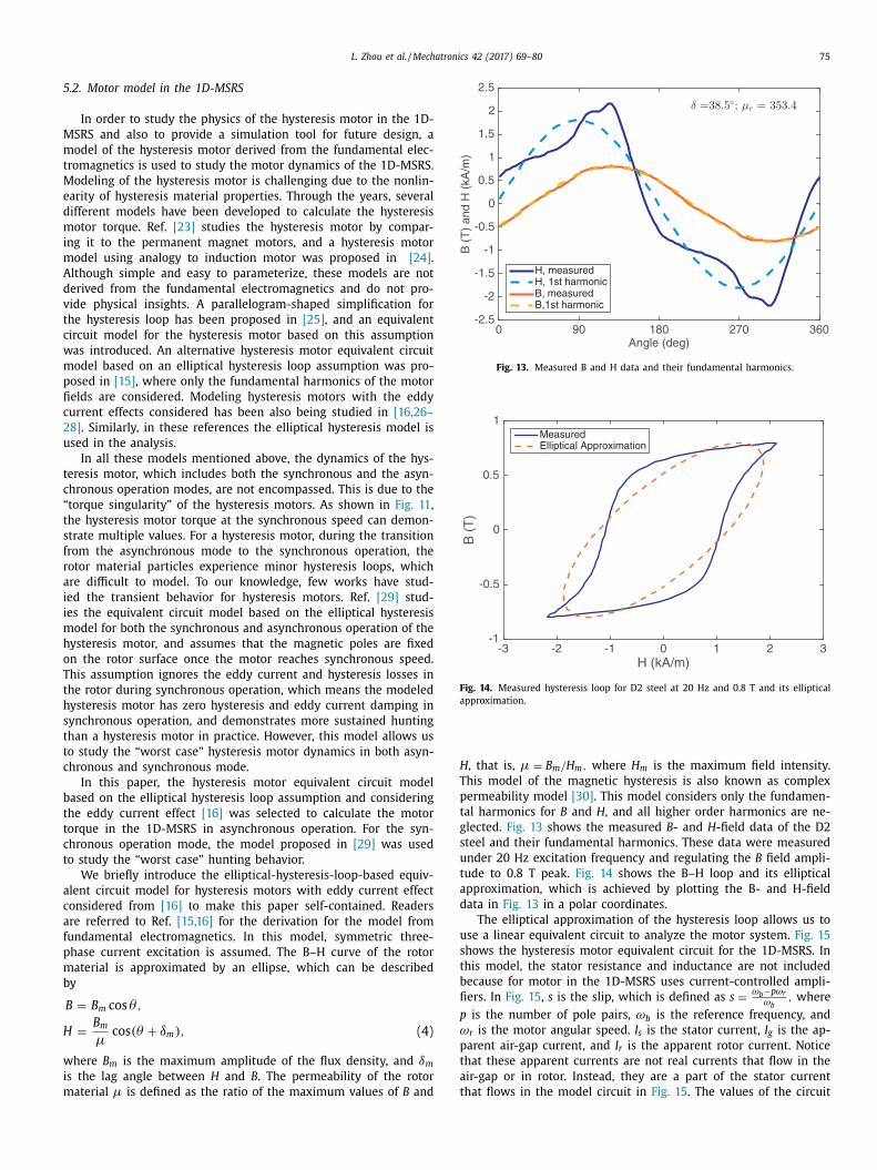
H , that is, µ = B m / H m , where H m is the maximum field intensity. This model of the magnetic hysteresis is also known as complex permeability model [30] . This model considers only the fundamen- tal harmonics for B and H , and all higher order harmonics are ne- glected. Fig. 13 shows the measured B - and H -field data of the D2 steel and their fundamental harmonics. These data were measured under 20 Hz excitation frequency and regulating the B field ampli- tude to 0.8 T peak. Fig. 14 shows the B–H loop and its elliptical approximation, which is achieved by plotting the B- and H-field data in Fig. 13 in a polar coordinates.
The elliptical approximation of the hysteresis loop allows us to use a linear equivalent circuit to analyze the motor system. Fig. 15 shows the hysteresis motor equivalent circuit for the 1D-MSRS. In this model, the stator resistance and inductance are not included because for motor in the 1D-MSRS uses current-controlled ampli- fiers. In Fig. 15 , s is the slip, which is defined as s = ω b −pω r
ω b , where p is the number of pole pairs, ω b is the reference frequency, and ω r is the motor angular speed. I s is the stator current, I g is the ap- parent air-gap current, and I r is the apparent rotor current. Notice that these apparent currents are not real currents that flow in the air-gap or in rotor. Instead, they are a part of the stator current that flows in the model circuit in Fig. 15 . The values of the circuit

76 L. Zhou et al. / Mechatronics 42 (2017) 69–80
Fig. 15. Equivalent circuit model of hysteresis motor considering the eddy current effect. elements can be calculated by [16] L g = 2 m K w 2 N 2 µ0 lr g
p 2 πg 0 , (5) R hr = ω b m K w 2 N 2 V r µ
π2 r r 2 sin δ, (6) L hr = m K w 2 N 2 V r µ
π2 r r 2 cos δ, (7) R e = 6 m K w 2 N 2 l
π r r t r σ . (8) Here δ is the separation angle between the B -field and H -field in the rotor material, K w is the winding factor, m is the number of phase, p is the number of poles, r r is mean radius of length of the magnetic field path within rotor, r g is the mean radius of the air gap, ω b is the input synchronous speed, N is the number of wind- ings per phase, g 0 is the air-gap length, µ is the permeability of the rotor material, l is the rotor length, σ is the conductivity of the rotor material. t r is the effective rotor depth. For solid rotor hys- teresis motors, it is defined as the skin depth of the rotor, which is calculated by t r = !
2 ω b µσ . V r is the effective rotor volume, which
can be calculated by V r = 2 π r r t r l. The apparent current values can be solved from the equivalent
circuit model shown in Fig. 15 . The motor electrical torque can then be calculated by [16] T e = m
2 p 2 L g I r I g sin δ. (9)
The rotor speed can be found from the mechanical dynamic equation for the rotor as J p d ω r
d t = T e − A | ω r | ω r , (10) where A is the coefficient of the air drag torque, and J is the rotor inertia.
Recall that the angle δ is the spatial separation angle between the B-field and H-field in the rotor material, which cannot exceed the lag angle of the rotor material hysteresis loop δm . Therefore the angle δ satisfies the constraint −δm < δ < δm , (11) where δm is the hysteresis loop lag angle given in Eq. (4) . When the hysteresis motor is operating in asynchronous mode, the lag angle is equal to its maximum, which is δm .
When the rotor’s mechanical speed reaches the vicinity of syn- chronous speed, the rotor magnetic pole aligns with the rotor me- chanical angle. Under the assumption of the magnetic poles of the
Fig. 16. Measured and simulated 1D-MSRS speed under excitation current of 0.45 A.
Fig. 17. Zoomed in measured and simulated 1D-MSRS speed under excitation cur- rent of 0.45 A. rotor are not moving with respect to the rotor material after the motor reaches synchrony, the angle δ can be updated by the dy- namic equation d δd t = ω b − ω r
p . (12) Introducing Eqs. (11) and (12) in the hysteresis motor equivalent circuit model allows the model to describe the motor behavior in both synchronous and asynchronous operation. As was discussed in [29] , when the motor slip is large, the constraint in (11) is activated, and the angle δ always equal to δm . This models the constant B- and H-field separation angle in the hysteresis mate- rial when the motor is in asynchronous operation. When the rotor speed is close to the synchronous speed, (12) is activated to de- scribe the dynamics of angle δ, which models the hunting behavior of the hysteresis motor.
Numerical simulations of the hysteresis motor in the 1D-MSRS were conducted by solving the equivalent circuit model and us- ing (5)–(12). Fig. 16 shows the simulated and experimentally mea- sured motor starting speed data plotted together, and Fig. 17 shows the zoomed-in speed data around the synchronous speed. It can be seen that the simulation and the experimental data align well in the accelerating transient. However, when the motor reaches synchronous speed, the simulated speed data demonstrates a less damped speed hunting behavior than the experimental measured speed data. This observation is consistent with our expectations that with the assumption that the magnetization is fixed on the rotor once the motor gets into synchronized operation, the mod- eled speed will demonstrate more oscillation because the hystere- sis and eddy current damping are not modeled.

L. Zhou et al. / Mechatronics 42 (2017) 69–80 77 Table 3 Torque simulation results with different rotor material properties. AlNiCo rotor material data taken from [31] .
Material µr δ [deg] Hysteresis torque at 0.7 A excitation [mNm] D2 steel 350 35 4 .15 AlNiCo ( H c = 11 . 1 kA/m ) 60 42 14 .9 AlNiCo ( H c = 15 . 9 kA/m ) 45 48 16 .2
Fig. 18. Block diagram of the reaction sphere speed control loop. 5.3. Speculation on performance with other rotor materials
Although only one kind of rotor material, D2 steel, has been tested in the 1D-MSRS hardware, the model of the hysteresis mo- tor presented in the previous section allows us to estimate the motor performance with other rotor materials. Table 3 presents the complex permeability values of two different kinds of semi- hard AlNiCo magnetic materials [31] , which are commonly used in hysteresis motor rotors, along with predicted resulting hysteresis torque. 5.4. Hysteresis motor speed control
When a hysteresis motor is operating, a speed fluctuation slightly above and below the reference speed can be observed when the motor speed reaches synchronous speed, as is seen in Fig. 17 . This motor dynamics is known as hunting [32] . It is unde- sirable when a hysteresis motor is used in a reaction wheel or a reaction sphere, as it will introduce vibrations to the spacecraft via the associated oscillatory torque.
To suppress the motor hunting, a feedback loop on the sphere’s rotational speed can be designed and implemented for the 1D- MSRS. Fig. 18 shows a block diagram of the speed control loop. The sphere speed ω r is measured by an optical tachometer. The input signal to the controller is the speed error e ω between the desired synchronous speed ω b and the measured speed ω r . The control ef- fort signal is defined as the zero-to-peak amplitude of the three- phase excitation current signal I m . In this analysis let us call it u , denoting the control effort. Note that in this system the value of u is non-negative, and it cannot go below 0.2 A in order to maintain the lateral suspension of the sphere. Also note that in this control system a positive control effort provides decelerating torque when e ω is negative.
When the reaction sphere is accelerating, it is desired that the motor can catch up with the reference speed, or the synchronous speed, as fast as possible. In optimal control, the minimum time problem with the presence of constraints for control effort can be solved, and the result shows that a bang-bang controller is the best mechanism for achieving minimum speed rise time [33] . For the 1D-MSRS, this requires the motor to operate in open-loop with the
Fig. 19. A comparison of experimental open-loop step response speed data and the closed-loop step responses speed data of reaction sphere. The open-loop step re- sponse is measured under a peak current amplitude of 0.35 A. maximum allowed excitation amplitude, which enables the motor to accelerate with its maximum ability.
In order to add active damping to the system to suppress the hunting, a lead filter is used as the speed controller when the hunting is happening. Define the maximum available control effort as u max . The speed control law of the 1D-MSRS can be written as u = "u max if e ω > ' or e ω < −',
u PD if −' ≤ e ω ≤ ', (13) where ' is a constant positive number that sets the threshold of the controller change.
The parameters of the PD controller are determined by the characteristics of the hunting dynamics. For the 1D-MSRS hard- ware, the motor hunting is at a frequency of 3.9 rad/s. Targeting at damping out this oscillation, the PD compensator for the reaction sphere’s speed regulation is designed as u PD (s ) e ω (s ) = 3 . 5 0 . 4 s + 1
0 . 04 s + 1 . (14) The speed controller given in Eqs. (13) and (14) was imple-
mented for the 1D-MSRS. Fig. 19 shows a comparison between the experimental measured open-loop transient speed data and the

78 L. Zhou et al. / Mechatronics 42 (2017) 69–80 Table 4 Specifications for MicroWheel 200 (MW200) reaction wheel from Microsat Systems Canada Inc.
Specification MSCI MW200 [34] 1D-MSRS Size 100 × 90 × 90 mm 120 × 120 × 110 mm Mass 1.0 kg (assembly for one wheel) 0.63 kg (rotor) + 0.42 kg (Stator + vertical suspension actuator) Torque capacity 26 mNm 8.9 mNm under 0.7 A excitation Angular momentum capacity 0.18 Nms 0.23 Nms (synchronously at 150 Hz/90 0 0 rpm) Motor power consumption 0 rpm: 3 .0 W; 1800 rpm: 5.5 W; Operating in steady state at 1800 rpm: 3.44 W
Fig. 20. Open-loop and closed-loop control effort data (peak amplitude for motor currents). closed-loop controlled speed data. The open-loop data was mea- sured with I m = 0 . 35 A , and the maximum allowed control effort was set to be 0.5 A. It can be seen from Fig. 19 that the closed-loop speed has much less oscillation when the speed enters synchrony. This verifies that the designed speed control scheme can effec- tively suppress the motor hunting. The corresponding motor wind- ing current signals are presented in Fig. 20 . With closed-loop con- trol, the motor current peak value reduces to 0.2 A when the reac- tion sphere is operating in steady state, which allows less energy loss at steady state operation. Experiments show that when oper- ating in steady state at 1800 \ \ text{rpm}, the power consumption of the 1D-MSRS, including both rotation and lateral magnetic suspen- sion (not including magnetic suspension in the vertical direction), is 3.44 W. This includes 0.52 W windage power loss, 2.84 W sta- tor copper loss, and 0.08 W for other miscellaneous power losses. Note that when the hysteresis motor in the 1D-MSRS is operating synchronously, the magnetization of the rotor is fixed with respect to the rotor surface, and therefore there is no eddy current loss or hysteresis loss in the rotor at steady state. 6. Discussion
A comparison between the test results of the 1D-MSRS and the specifications of a commercial reaction wheel assembly for typi- cal small satellites is performed, as is shown in Table 4 . Here the MicroWheel 200 (MW200) Reaction Wheel from Microsat Systems Canada Inc. [34] is chosen as a benchmark, which has a similar size to the 1D-MSRS prototype.
Data in Table 4 shows that the torque capacity of 1D-MSRS is smaller than that of the MW200 reaction wheel. The reason, to our understanding, is threefold. First, hysteresis motors are not win- ning in their torque ability compared with their permanent mag- net motor counterparts. Second, D2 steel is not the best rotor ma- terial for hysteresis motors. The simulation results presented in Section 5.3 show that larger torque capability can be achieved if the rotor has a better hysteresis properties. Third, in the design of the 1D-MSRS, the effective surface area on the rotor for torque production is small, since the stator height is relatively small.
In Table 4 , comparing with MW200 reaction wheel, the 1D- MSRS has a larger angular momentum capacity since it can run up to a higher synchronous rotational speed. We believe that the sphere can reach a higher synchronous speed when running in vacuum, where the air drag can be eliminated as well. In addi- tion, the 1D-MSRS demonstrates lower power consumption when operating in steady state. This is a direct result of magnetic sus- pension which eliminates mechanical friction. This comparison demonstrates a good potential of hysteresis motors for the devel- opment of high speed, low vibration reaction wheels/spheres, es- pecially when they are assisted with magnetic suspension.
Another potential advantage of the 1D-MSRS over permanent magnet motor driven reaction wheels with mechanical bearings is that it may be easier to achieve smaller rotor imbalance. The rea- son is twofold. First, the rotor of a hysteresis motor can be made out of solid steel, while the rotor for a permanent magnet motor usually requires a multi-part assembly. It is usually easier to make a solid rotor to achieve small imbalance. Second, when the mo- tor is operating at high speed, the magnetic suspension can elim- inate imbalance and allowing the rotor to spin about its inertial axis. Therefore with a hysteresis motor driven actuator supported by magnetic bearings, the vibrations emitted by the reaction wheel that degrade the performance of precision instruments in space may be reduced. 7. Conclusion and future work
The design and development of a hysteresis motor driven mag- netically suspended one-axis reaction sphere is presented in this paper. Magnetic suspension, bearingless drive and hysteresis mo- tor principles are used in the design of the 1D-MSRS. An analytical dynamic model of the bearingless motor suspension system is de- rived and used for the suspension control design. An equivalent circuit model for hysteresis motors is used to analyze the motor dynamics of the 1D-MSRS, and a speed control loop is built for the system to suppress hunting. The 1D-MSRS can run up to 200 Hz (12,0 0 0 rpm) in the presence of air drag, and a starting torque of 8.9 mNm is generated with 0.7 A excitation current amplitude. This study demonstrates that the hysteresis motor has a good potential for reaction wheel/sphere applications.
Future work should consider the design and development of a three-axes magnetically suspended reaction sphere (3D-MSRS). Several discussions of the possible motor concepts and possible magnetic pole configuration designs for a 3D-MSRS are presented in [21] . However, we have not yet discovered a good motor config- uration for the 3D-MSRS driven by hysteresis motor. We hope that this work on the 1D-MSRS can inspire promising future designs.
In addition, the performance of the 1D-MSRS demonstrates that the hysteresis motor has the potential for high speed, low vibra- tion in reaction wheel applications. Future work should consider hysteresis motor driven single-axis reaction wheel designs that op- timizing the power efficiency and device volume. Many important aspects for space actuators, such as cooling, back-up bearings, as- sistive device for magnetic bearing during launching should also be studied in future effort s.

L. Zhou et al. / Mechatronics 42 (2017) 69–80 79 Acknowledgments
We thank National Instruments for contributing the real-time controller. We thank Professor Wolfgang Gruber at JKU, Linz for the valuable discussions, and thank Dietmar Andessner at JKU, Linz for his help with the hysteresis measurements.
This work is supported by the MIT Lincoln Laboratory via the Advanced Concepts Committee. We also thank Frederick Knight and Andrew Stimac of Lincoln Laboratory for their assistance with this project. References
[1] Bialke B . High fidelity mathematical modeling of reaction wheel performance. Guid Control 1998:483–96 .
[2] Fukada T , Hosokai H , Yajima N . Flexibility control of solar battery arrays: 3rd report vibration and attitude control with consideration of the dynamics of a reaction wheel as an actuator. Bull JSME 1986;29(255):3121–5 .
[3] Ormsby RD . Capabilities and limitations of reaction spheres for attitude con- trol. ARS J 1961;31(6):808–12 .
[4] Tierney TE , Curran RJ . Development of an electrostatic suspension reaction sphere. Technical report. SAE Technical Paper; 1964 .
[5] Isely W.H.. Magnetically supported and torqued momentum reaction sphere, US Patent 4,611,863. 1986.
[6] Nakanishi T., Ando Y., Sakakibara K.. Electric motor having a spherical rotor and its application apparatus. US Patent 5,413,010. 1995
[7] Onillon E , Chételat O , Rossini L , Lisowski L , Droz S , Moerschell J . Reaction sphere for attitude control. In: Proceedings of the 13th European Space Mech- anisms and Tribology Symposium; 2009 .
[8] Chabot J , Schaub H . Spherical magnetic dipole actuator for spacecraft attitude control. J Guid Control Dyn 2016:911–15 .
[9] Rossini L , Chételat O , Onillon E , Perriard Y . Force and torque analytical models of a reaction sphere actuator based on spherical harmonic rotation and de- composition. IEEE/ASME Trans Mechatron 2013;18(3):1006–18 .
[10] Vachtsevanos G.J., Davey K.R. Spherical motor particularly adapted for robotics, US Patent 4,739,241. 1988.
[11] Lee K-M , Roth RB , Zhou Z . Dynamic modeling and control of a bal- l-joint-like variable-reluctance spherical motor. J Dyn Syst Meas Control 1996;118(1):29–40 .
[12] Yano T , Suzuki T . Basic characteristics of the small spherical stepping motor. In: Proceedings of the IEEE/RSJ International Conference on Intelligent Robots and Systems, 2. IEEE; 2002. p. 1980–5 .
[13] Lee K-M , Sosseh RA , Wei Z . Effects of the torque model on the control of a VR spherical motor. Control Eng Pract 2004;12(11):1437–49 .
[14] Kumagai M , Hollis RL . Development and control of a three DOF spherical induction motor. In: Proceedings of the IEEE International Conference on Robotics and Automation (ICRA). IEEE; 2013. p. 1528–33 .
[15] Miyairi S , Kataoka T . A basic equivalent circuit of the hysteresis motor. Electr Eng Jpn 1965;85:41–50 .
[16] Miyairi S , Kataoka T . Analysis of hysteresis motors considering eddy current effect. Electr Eng Jpn 1966;86(6):67 .
[17] Andessner D , Kobler R , Passenbrunner J , Amrhein W . Measurement of the magnetic characteristics of soft magnetic materials with the use of an itera- tive learning control algorithm. In: Proceedings of the IEEE Vehicle Power and Propulsion Conference. IEEE; 2011. p. 1–6 .
[18] Chiba A , Fukao T , Ichikawa O , Oshima M , Takemoto M , Dorrell DG . Magnetic bearings and bearingless drives. Burlington, MA: Elsevier; 2005 .
[19] Lu X , et al. Electromagnetically-Driven Ultra-Fast Tool Servos for Diamond Turning. [Ph.D. thesis] Department of Mechanical Engineering, Massachusetts Institute of Technology; 2005 .
[20] Zhou L , Trumper DL . Reluctance force magnetic suspension characteristics and control for cylindrical rotor bearingless motors. J Dyn Syst Meas Control 2017;139:031003–031003-8 .
[21] Zhou L . Magnetically suspended reaction sphere with one-axis hysteresis drive. Mechanical Engineering, Massachusetts Institute of Technology; 2014. [Master’s thesis] .
[22] Teare BR . Theory of hysteresis-motor torque. Electr Eng 1940;59(12):907–12 . [23] Rahman MA . Analytical models for polyphase hysteresis motor. IEEE Trans
Power Appar Syst 1973(1):237–42 . [24] O’Kelly D . Theory and performance of solid-rotor induction and hysteresis ma-
chines. In: Proceedings of the Institution of Electrical Engineers, 123. IET; 1976. p. 421–8 .
[25] Copeland M , Slemon G . An analysis of the hysteresis motor I-analysis of the idealized machine. IEEE Trans Power Appar Syst 1963;82(65):34–42 .
[26] O’Kelly D . Eddy-current and hysteresis effects in rotating machines. Proc Inst Electr Eng 1969;116(3):391–4 .
[27] Kataoka T . Unified analysis of solid rotor induction and hysteresis motors. Electr Eng Jpn 1975;95(3):60–7 .
[28] O’kelly D . Theory and performance of solid-rotor induction and hysteresis ma- chines. Proc Inst Electr Eng 1976;123(5):421–8 .
[29] Nitao J , Scharlemann E , Kirkendall B . Equivalent circuit modeling of hystere- sis motors. Technical report. Lawrence Livermore National Laboratory (LLNL), Livermore, CA; 2009 .
[30] Zaher FA . An analytical solution for the field of a hysteresis motor based on complex permeability. IEEE Trans Energy Convers 1990;5(1):156–63 .
[31] Horii T , Yuge N , Wakui G . Analysis of a hysteresis motor on asynchronous speed using complex permeability. IEEE Transl J Magn Jpn 1994;9(2):135–42 .
[32] Clurman S . On hunting in hysteresis motors and new damping techniques. IEEE Trans Magn 1971;7(3):512–17 .
[33] Bryson AE . Applied optimal control: optimization, estimation and control. Levittown, Pennsylvania: CRC Press; 1975 .
[34] . MicroWheel 200 (MW200) reaction wheel. Technical report. Microsat Sys- tems Canada Inc.; 2001 .

80 L. Zhou et al. / Mechatronics 42 (2017) 69–80 Lei Zhou received the B.S. degree from the Tsinghua University, China, in control and instrumentation technology in 2012, and received M.S. degree from the Massachusetts Institute of Technology (MIT) in mechanical engineering in 2014. She is currently working toward the Ph.D. degree at the Department of Mechanical Engineering at MIT. Her research interests include dynamic systems, control, and precision mechatronics. Mohammad Imani Nejad received the Ph.D. degree in Mechanical Engineering from the Massachusetts Institute of Technology (MIT), Cambridge, USA, in 2013. Since then, he has been with IIMANII, Inc., Boston, USA, where he is currently the Senior Director of Technology and R&D. David L. Trumper joined the Massachusetts Institute of Technology (MIT) Department of Mechanical Engineering in August 1993, and holds the rank of Professor. He received the B.S., M.S., and Ph.D. degrees from MIT in Electrical Engineering and Computer Science, in 1980, 1984, and 1990, respectively. Following the Bachelor’s degree, Professor Trumper worked two years for the Hewlett–Packard Co. After finishing the Master’s degree, he worked for two years for the Waters Chromatography Division of Millipore. Upon completing the Ph.D. degree, for three years he was an Assistant Professor in the Electrical Engineering Department at the University of North Carolina at Charlotte, working within the precision engineering group. Professor Trumper’s research centers on the design of precision mechatronic systems, with a focus on the design of novel mechanisms, actuators, sensors, and control systems. He has conducted research in topics including precision motion control, high-performance manufacturing equipment, novel measurement instruments, biomedical and bioinstrumentation devices, and high-precision magnetic suspensions and bearings. He is a member of the IEEE, ASME, and ASPE (past-President).