Embed Size (px)
Citation preview

i I
,·
.0..
I
i •• r: - t
Preliminary Dra~
PAP 16 .
HYDRAULICS BRANCH OFFICIAL FILE COPY
,_. ....... -FILE COPY
WHEN BORROWED RETURN PROMPTLY
Hydraulic Design Considerations
for
High-head Outlets
Gates and Valves
by
James W. Ball
May 1962

> .I
HIGH-HEAD RESERVOIR OUfLEI'S
High-head reservoir outlets are defined as conduits which release
water from reservoirs under heads of 100 or more feet for flood
control, irrigation, domestic supply, and power. These outlets
may be divided into four general types: (l) those having no
restriction or control device such as gates or valves within
them; (2) those having a control or regulating device at the
upstream end; (3) those having a control or regulator at some
intermediate point, and ( 4) those having the control or regulator
at the downstream end.
The first type is usually employed strictly for flood control, while
the other three Ii:tay serve to control or regulate flows for other
purposes as well as for flood control.
'YI.A~);~µ ~~o~ There are four impdi:tant11~~ in outlets: (l) the
entrance; (2) the control or regulator; (3) the main conduit, ~ .'..l>.A(\~ ~ ... w
and (4) the exit. In general, these 1:n.•eeleml!' apply to all four r:-o , -~ t,Jl)J '" • ~) '\ '\.~ I •' • V
of the general types. .Prob] ems vary somewhat in the different
types.
One of the first considerations in planning an outlet is to
select the type best suited to the requirements. Hydraulic
adequacy must be considered along with economics.
I
J I

.. ,
·'
Once the most appropriate and economical type of outlet has been
determined, the next important step is to ascertain the size
needed. Tris can best be done by equating the total hydraulic
losses to the design head, using the design discharge. One of
the most convenient meth~s ~ tb ~xpress th~ losses in terms of 2 l,l.,~r d];~ AC..~1t--N
the velocity head(~); eq'II"ating total ~ osses to the design head, cg I\
expressing velocity in terms of Q/A, (Q=AV); computing A (area
of outlet) and determining diameter or dimensions for this area.
In this case, losses would be expressed thusly: . v2
K.~, where K is the loss coefficient for the outlet
component being considered. The losses may include: (1)
Trashrack loss; (2) entrance loss (varies with shape); (3)
friction loss; (4) shape loss (bends, junctions, expansions,
contractions, etc); (5) control or regulator loss, and (6)
exit loss.
The value of K for trashracks is small, about 8 times the
velocity head at the trashrack. Trashrack velocities are
usually between 1 and 2 feet per second, so omission of the loss
in initial plans would not be significant.
The value of K for the entrance will vary with a sharpness of
the entrance and will range from o.o4 for a well shaped
bellmouth , 0.25 for a slightly rounded, 0.50 for a sharp edged,
to 0.80 for an inward projecting entrance.
2 / /
/

The value of K for friction loss will vary with velocity of
flow, viscosity of fluid, diameter of conduit, le~h of
conduit, and relative roughness of the flow boundary surfaces • .f. 2
The Darcy formula H =..«... _l_ l is a convenient relationship d 2g -1,,
to determine friction loss. The factor f is termed the
friction factor and is dependent on the velocity of flow, kinematic
diameter of conduit,/~ viscosity of the fluid and the
relative roughness of the conduit flow surface. The friction
factor can be obtained by use of appropriate surface rugosity
values, viscosity, and the well known Moody diagram. Values
usually range from about O.Oo8 to 0.04,depend.ing on the values
of the parameters enumerated above. Data from many tests
made throughout the world have been compiled in Bureau of
Reclamation Monograph No. 7.
The values of K for special conduit shapes, such as bends,
branches, junctions, enlargements, and contractions, vary
with the shape. Values may be obtained from data gathered from
many parts of the world.Y 2f §/
1/ A,1.>..b.x.i ¢..<'>(I~~ (µl.J~ ) '-~--- .l ( The value of K for the control or regulating deviceAca.n be of
particular importance because it varies widely for the different
types of controls. The expression K= (-fu - 1), where C is the
"' 4/(British publication) 5/(translation) y
3
• T'
-!
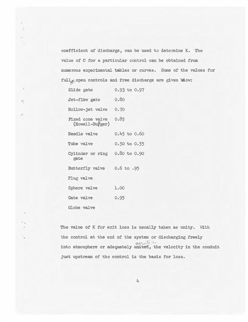
coefficient of discharge, can be used to detennine K. The
value of C for a particular control can be obtained from
numerous experimental tables or curves. Some of the values for
full~ open controls and free discharge are given bi.ow:
Slide gate 0.93 to 0.97
Jet-fl.ow gate 0.80
Hollow-jet valve 0.70
Fixed cone valve 0.85 (Howell-Bufger)
Needle valve o.45 to 0.60
Tube valve 0.50 to 0.55
Cylinder or ring o.80 to 0.90 gate
Butterfly valve o.6 to .95
Plug valve
Sphere valve 1.00
Gate valve 0.95
Globe valve
The value of K for exit loss is usually taken as unity. With
the control at the end of the system or discharging freely _., ,
Q.11,A.o..U. '• into atmosphere or adequately .unit~d, the velocity in the conduit
just upstream of the control is the basis for loss.
4

..
Summing up and equating losses to available head (H) as:
Expressing Vin te:rms of Q and A:
2-K 2)~ = H
Select Q and solve for A (needed area). Compute conduit
dimensions ~ e A.
One of the most important hydraulic considerations when designing
an outlet is the cavitation potential of its various parts.
Cavitation is a phenomenon that takes place when the pressure
within the fluid reaches the vapor pressure of the fluid for the
existing temperature.\(por cavities form and then collapse as
they pass suddenly into a higher pressure area, producing high
unit forces which damage flow surfaces of any material when in
contact with them. Cavitation may occur at the entrance, within
the outlet, or at or within the control or regulator.
\
5

.•
Conduit and Penstock Entrances
Entrances of penstocks and conduits are usually streamlined. The
entrances for power penstocks are designed for a minimum of less
and this requires good streamlining. Conduits that carry high
velocity flow (in excess of 50 feet per second) also require
streamlined entrances. The streamlining in this case is needed
to prevent regions of reduced pressure which might cause' cavi- . ~A-1 ~1,~'J
tation. Streamlining in these areas ., usually/ surfaces \f~ \
to the shape of an ellipse. Suitable shapes for circular and
rectangular entrances have been developed by laboratory
investigations __ /_/_/ General static pressures will influence
the streamlining. Less streamlining is necessary when the static
pressures (back pressures) are high .
Smoothness of flow surfaces
Where velocities are high and static pressures are low) it is
important that flow surfaces not contain roughness or irregularities
that would cause a local reduction in pressure that would induce
cavitation. The cavitation potential of possible surface irrigularities
should be investigated during the design stage. The potential of
a given type of irregularity will vary ·with the size of the irregu
larity, the flow velocity, and the static pressure in the vicinity
of the irregularity. Hydraulic tests have been made for
Several Shapes . - /_ /_/ Curves~ showing critical velocities
6

and pressures for sharp c~ offsets into the flow are shown
on Figure Partially open valves or gates in closed -----lines can be treated as irregularities in water passages . The
• .A.u~~ ;it- .,,_c ~ cavitation potential of such arrangement~has been st~d by
~
evaluating the cavitation index Kin terms of the pressure,
vapor pressure, and the velocity. The following relationship has
been found useful in this respect.
K = H2 - Hv
Where H2
is pressure; short distance downstream from the control,
Hv ~s vapor pressure of water relative to atmosphere, and Ht
is total head just upstreat from control. Results have shown that
very mild cavitation occurs for K ~ 1.0, that there is no
cavitation whatsoever for K ji 2.0, and that cavitation intensity
increases as K decreases below unity .
7

.,.
IR.AFT JWBall:saj-s
Gates
Control gates may be classified generally as leaf gates, or gates in
which a structural leaf is used to regulate or control the flow from
closed conduits. Leaf gates may be classified further according to
some particular feature or purpose, such as, slide gates, ring-follower
gates, fixed-wheel gates, tractor gates, jet-flow gates, radial gates,
and bulkhead gates. The physical and hydraulic characteristics of
gates vary widely, thus each should be considered in the light of these
characteristics and the purpose of the gates is to serve. 'Ihe various
gate~, their characteristics and use, are discussed so that proper
selection of the design can be made.
Slide Gates
A slide gate is one with a rectangular or square leaf, usually of cast
iron or steel, contained in a cast iron or steel housing or body. The
leaf slides on special sealing surfaces in side grooves in the body to
shut off the flow. The leaf seats and seals on the flat bottom surface
of the gate body. Guides, wheels, rolls or tracks are o~en used to
reduce the sliding friction between leaf and body.Slide gates may be
classified further depending on purpose to be served, or some hydraulic
or physical characteristic. Some of these gates will be of particular
interest.

Ring-follower gate.
This gate has a leaf that is solid at one end and has a hole in the
other which is the same diameter as the conduit. The leaf slides in
grooves in the gate body. The solid end shuts off the flow and the
end with the hole in it forms a continous flow passage when the leaf
is in the wide open position. The name of this gate originates from
· the fact that ring (end of leaf with hole) follows the shut-off portion
of the leaf to form the continuous water passage for the fully-open ring-
pasition. The/follower gate offers essentially no resistance to flow
and is therefore the most efficient of the many types of gates and
hydraulic losses need not be considered. However, this gate is not
to be used at partial openings for flow regulation at high heads. The
sharp corners of the opening through the leaf and the body are conducive
to cavitation and this would induce noise, vibration, and distructive
pitting. These conditions are prevailent during the opening and
closing cycle but the duration is so short that there are no serious
problems. The opening in the gate leaf should coincide with the conduit
to form continuous flow surfaces in the water passage when the gate is in
the wide open position.
The ~ :hydraulic downpull on the ring-follower gate is an important
factor to be considered because the design of the operating equipment is
dependent on the magJl'tx'JQli magnitude of this force. This downpull force
can be controlled to some degree by providing adequate clearances between
the leaf and portions of the gate body. The Paradox gate and ring-seal

. ,
gates are variations of the ring-follower gate, in which the sealing
devices differ materially. These gates are usually placed at some
intermediate point in the conduit, either as a non-regulating control,
or a guard gate. Adequate areation to prevent general areas of severe
subatmospheric pressure with resultant objectionable noise and vibration,
should be provided •
Jet-flow Gate
The jet-flow gate is one in which an orifice is built into the gate
body joint upstream of the leaf to cause the flow to form a contracted
~ jet which passes through the gate body without contacting the
gate grooves. The contraction facilitates aeration of the conduit
downstream from the gate and because a contraction is present at all gate
openings, the gate can be used as a flow· regulator as well as a control.
Also, the downstream conduit may be either circular, rectangular, horse
shoe or other shape without introducing difficulties. However, any
transition from one shape to another downstream from the gates should be
given careful consideration regarding surface irregularities and alignment.
The diameter of the orifice should be equal to or less than that of the
upstream pipe. The diameter of the pipe at the orifice should be about
1.2 times the diameter of the orifice. This deminsion may be obtained
by an expansion or enlargement of the pipe section just upstream from the
orifice or by using an~ upstream pipe 1.2 times the diameter of
the orifice. For this setting and diameter
relationships the coefficient of discharge is 0.8o based on the orifice dia
meter and the toaal head upstream from the gate. The pressure drop for

. ,
. -
would be about 0.56 v2 , where Vis the average velocity at gate orifice. 2g
The smooth upstream force of the gate leaf remains in contact with the
seal which is contained in the gate body on the downstream side of the
orifice. This sealing at the upstream side of the leaf virtually
eliminates the hydraulic downpull force which can be quite large for slide
gates •
Regulating Slide Gate
The early designs of the slide gate gave no consideration to the shape
of the flow passage at the gate grooves or slots, or to the shape of
the gate bottom. These early designs had a high cavitation potential
for high heads and many incurred severe destructive pitting damage.
Particular attention has been given to gate slot shape and size, shape
of bottom surface and the contour of the upstream force of the gate leaf
in designs developed in recent years. As a result there are now designs
with very low cavitation potential (Figure ). The gate slots
in these gates have offset downstream corners and curves or flat converging
surfaces connecting the corners to the downstream gate frame walls. The
proper proportions for gate slots that minimize cavitation have been
/?P.f) 105/ determined through research stutlies.---- Many gate bottom shapes have
been considered but the 45° slope with a flat sealing surface has proven
111.&Ki! most desirable. This shape is very effective in reducing hydraulic
downpull.
)5 II

In early designs the upstream face of the leaf was curved in the
horizontal plane, making it quite thick at the center; at smaller
openings this shape caused the flow allli to concentrate in the center
of the downstream channel and give very poor distribution of flow for
stilling Ba.sins. Gate leaves arenow made flatter and thinner. The
roof of' the f'ra.nejust downstream from the gate leaf is usually offset
upward to facilitate aeration. This regulating slide gate can now be
used either within or at the end of' a tunnel. The coefficient of
discharge for this gate is about 0.95, but may vary from 0.92 to 0.97
depending on upstream conditions. The l~? s factor or pressure dr~ for the
0.95 discharge coefficient is about 0.11 v2, The design of the water 20
passage upstream from these high capacity gates should be given careful
consideration regarding surface irregularities and alignement in order
that the system will have a low potential for cavitation, vibration,
and noise.
I 2,-,

-,.
DRAFT JWB.ALL:fhr-s April lJ, 1962
Bulkhead Gates
A bulkhead gate is one that is used for isolating the flow system or
a part of it to permit inspection or repairs. The shapes of bulkhead
gates may vary widely depending on where and how they are to be used.
The bulkhead gates employed in unwatering outlet works conduits are
usually rectangular in shape and are generally placed over the up
stream ends of the conduits by using hoists and sliding them in
guides on the upstream faces of the structures. They are generally
known as coaster gates . A bulkhead gate is usually positioned under
balanced pressurec conditions. However, in some cases where they
serve also as guard gates or energeney closure gates they are sub
jected to unbalanced pressures and careful consideration must be
given to their design and hydraulic characteristics. Cavitation
potential and b;ydraulic ~ are two important con
siderations. Floatation and stability may need to be considered
depending on how and where the gate is to be used and usually not
where high heads are involved. Where bulkhead gates operate for
emergency closure the downpull force can be quite large compared with
the weight of the gate._/ There are so many factors of gate design
that influence the downpull force that a general solution is not
possible. The following items are typical of those to be con-

sidered: (1) head on gate, (2) gate width, (3) gate thickness, .e,
(4) shape of ga'\e bottom surfacj , (5) type and shape of gate seal,
(6) trashrack base position, (7) pressures in conduit, and (8) con
figuration of face of dam near conduit entrance • The influence of
all but Item 4 and 8 can be adequately estimated. Sufficient data
are available on certain gate bottom shapes to permit a reasonably
accurate estimate of their influence. A recess in the face of the
structure above and near the conduit entrance would be an example
of Item 8. Hydraulic model tests may be needed to evaluate the
influence of such characteristics. (Note: Figures in Hyd 130 may be
useful).

DRAFT JWBall:awo-s April 19, 1962
Regulating Radial Gates
The radial gate receives its name from the fact that the leaf, or
closure element, is a segment of a cylinder and rotates about
the hinges which are on the framework arms that are radial to the
closure element. Radial gates are used extensively for open channel
regulation on spillway or canal. structures, but are also being used
to regulate closed conduit flow under moderate heads and where large
discharges are required. In the wide open position, the radial gate
offers essentially no resistance to the flow. The loss can be taken
the same as an equivalent length of water passage. When this is
done and there is no restriction due to seals or grooves the discharge
coefficient can be considered to be unity. These gates are sometimes
termed top-seal radial gates. These gates have been used successt'ully
for heads of llO feet. The seals on these gates are generally adequate
but further improvement is desirable. Bottom seals may be troublesome
by inducing vibration, depending on their nature and arrangement. The
music note, or bulb seal does not always give good results and,in
some cases, it has been necessary to replace this shape with a
simple bar shape rubber seal. Special pressure actuated seals
along the side and top have shown promise. The reaction of the
hydraulic forces on the radial gates are always radial and through
the trunion bearings of the gate arms.
-/p

--
Cylinder Gates
The designation "cylinder gate" is associated with gates having a
cylindrical closure element. This closure element is usually in
a vertical position and is raised and lowered from a circular seat
to regulate the flow. There are two general types o:f cylinder gates,
one in which the flow is outward from the conduit under the gate,
and the other in which the flow is from outside the conduit, under
the gate, and into the conduit. The magnitude, frequency, and
direction of the hydraulic :forces acting on the gate under various
operating conditions are important factors as they may introduce
vibration which might be damaging to the gate.
Seal and seat spacing and arrangement are important in order that
damaging cavitation with the inherent noise and vibration can be
avoided. Hydraulic downpull may or may not be a consideration,
depending on the gate shape. The gate bottom shape and the seat
ring configuration must be given careful consideration. Damping
devices may be needed on long gate operating stems to prevent
oscillation due to changing :flows on fluctuating pressures which
vary the elongation of' the stems. ibe losses f'or an intake gate
where water flows under the gate into the conduit can be considered
negligible, while losses for and outlet gate controlling flow from
the conduit is small. The coefficient of discharge f'or the intake
gate can be taken as unity. That for the outlet condition is about
0.85 to 0.90. This value can vary with the ratio of gate diameter to
gate travel.
~ lb

DRAFT JWBall:btm-s May 10, 1962
VALVES
Control valves may be classified generally as devices which use other
than a structural. leaf for regulating or controlling the flow from
closed conduits. Valves may also be classified as general types,
auch as, needle, tube, fixed cone, hollow-jet, butterfly, and plug
valves. Some of these types include several variations :.tax that will
be discussed under the appropriate topics.
Valves are usua.1.1.y employed where regulation of flow varies from
very small amounts to the full capacity of the system. ~ey may
be placed at the entrance, within, or at the end of conduits, but
are usually placed at the end of conduits where they discharge
freely into the atmosphere. ~e cavitation potential of the various
valve designs differ widely depending on configuration of the water
passages and under what conditions the valves are used. ~e hydraulic
and stnuctural characteristics of the various valves will be discussed
to assist in the selection of these valves for the purpose intended.
'!be coI!DilOn gate valve and the common globe valves will not be con
sidered as controls for high head outlets. However, when use of these
valves are contemplated,careful consideration should be given to their
flow characteristics and their cavitation potential.
I 7

DRAFT JWBall: fhr-s April 16, 1962
Report
Needle Valve
A needle valve consists of an outer shell or body with a stationary
cylinder supported within it on ribs or vanes and a closing or
regulating element telescoping either inside or outside of the
stationary cylinder. The needle valve is sometimes operated by
regulating hydraulic pressure within ·compartments formed by the cylinder
and closure element. The needle-like closure e1ement m::>ves down-
stream against a seating surface in the valve body to shut off the
flow. This places the valve body under internal pressures equal to
the reservoir head and requires that the body be of sufficient thick
ness to withstand these pressures. Because of this the needle valve
is usually quite heavy.
There have been variations of the needle valve in past years. The
Ensign valve, named for the prominent engineer who contributed to its
development, was an early model. This valve was usually attached to
the face of the structure over the conduit entrance and was quite
inaccesi ble . The valve was not suitable for high heads and much
difficulty ~ was experienced with cavitation when it was
used under these conditions. Trouble was experienced with cavitation
in soem of the early needle valves such as the Lamer-Johnson type
I e'

because of diverging water passages. This difficulty was overcome
by making the walls of the passage between the body and needle
parallel or slightly convergent.
The shaping of the water passage of the needle valve is quite importnat.
The contour of the passage as well as the area of flow should never
diverge because divergence will increase the cavitation potential. The
body surface should recede suddenly from the water passage at the
downstream end to provide complete separation and aeration of the jet.
The discharge coefficient of a cavitation-free needle valve design is
about 0.59 when based on the area of the inlet and the total head just
upstream. (In this case inlet diameter was 1.05 times exit diameter)
There should be no difficulty with cavitation when the proportions are
~shown in Figure Hydraulic forces on the needle point for all
operating conditions should be considered so that adequate actuating
mechanism can be provided. The needle valve discharges a solid con
centrated jet making special consideration necessary when the energy
in the jet is to be dissipated in a stilling basin.

Tube Valve
The tube valve consists of an outer shell or body with a stationary
cylinder supported within it on ribs or vanes and a closing or
regulating tube-like element telescoping inside the cylinder. The
regulating elem:?nt is operated me~hanically by a screw stem which
passes through the transverse spider spanning the upstream end of
the closure tube. The tube seats and seals of the downstream end of the
valve body and the body is therefore subjected to full reservoir
pressure when closed. The tubular closure ele:ioont is actuated by
level gearing driven through the shaft extension to a motor-reduction
gear unit attached to the valve body. The tube valve has essentially no
unbalanced hydraulic forces and therefore can be operated m:?chanically
without difficulty. The cavitation potential of the tube valve is quite
low because of the areas of the needle valve subjected to this action
were not present. For a valve with an inlet diameter 1.1 tires the
outlet diameter, the discharge coefficient was 0.52 based on the total
head and the area of the pipe just upstream from the valve • Flow from
the valve at large openings is a steady concentrated jet similar to that
for a needle valve.
The jet at small valve openings, below about 25 percent, pulsates and
has a ragged appearance. It is not considered desirable to operate
tube valves in this range for .long periods of time.

DRAFr JWBall:wab-s April 7, 1962
Hollow-jet Valve
The hollow-jet valve is a needle type valve having a bell-shaped
body with the larger bell-end directed downstream and the closure
element or needle pointed upstream. The closure element moves
upstream to shut off the flow as the needle seats against the body
in the neck or smaller section of the bell. (Figure ). The
portion of the valve body beyond the seat is never under reservoir
pressure, thus the valve is of relatively light weight construction.
Water passes between the closure element and the body, and dis
charges from the downstream end of the short bell-shaped body in a
tubular, or hollow jet, the outside diameter of which does not change
with valve opening. There is very little dispersion of the jet
regardless of opening; however, because of the tubular form of the
jet the energy is distributed over a comparatively large area,
facilitating the dissipation of energy and lessening the destructive
action in the stilling basin. A special economical stilling basin
11.'1.J , 446 / for hollow-jet valves has been developed by hydraulic model studies.~
The proportions of the water passage through the valve are designed
to prevent substmospheric pressures, thus assuring that cavitation
damage will not occur when the flow surfaces are smooth and contain
no objectionable irregularities. The pressures on the flow surfaces
;1.(

•
change with the movement of the closure element, decreasing as the
travel or opening increases. The normal travel of d was that deter-1
mined by model studies to give definite positive pressures on the
flow passage surfaces. The coefficient of discharge for this travel
and based on the total head and area one diameter upstream from the
valve is 0.70. The capacity of the valve can be increased some by
increasing the travel of the closure element. A 3-1/2 percent
increase in capacity can be obtained by a 5-1/2 percent increase
in travel without introducing subatmospheric pressures in the flow
passage. An extrapolation of the discharge coefficient and pressure
curves indicates that the travel can be increased by 10 percent with
out introducing serious subatmospheric pressures. The coefficient of
discharge for this increased travel would be about 0.75. The pres
sure intensity in various parts of the flow passage, and the coef
ficient of discharge variation with valve opening, expressed in
percent of travel of the closure element, can be determined from
graphs established through hydraulic model investigations (Figure ).
Proportions of the water passage and other parts of the valve can be
obtained from a ratio chart prepared for this purpose (Figure ).
As in all cases where surfaces are subjected to high velocity flow
there is danger of cavitation with damage, noise, and vibration
unless these surfaces are kept smooth and free of troublesome
irregularitiii~448/
2 2..

The pressure drop for this valve with a discharge coefficient of
v2 0.70 is about 1.04 ~ where Vis average velocity at the valve 2g
entrance.
For facilitating mechanical operation, the valve is provided with
an internal chamber which is connected to the flow surface by
0 equalizing p,rts. The use of these ports permits hydraulic forces
on the closure element to be balanced within plus or minus 13 per-
cent regardless of opening (Figure ) • This balancing reduced to
a minimum the mechanical forces needed for operation.
Hydraulic operation of the hollow-jet valve is now used extensively.
The balancing pGrts are of course omitted when hydraulic operation
is used.

Butter.fly Valves
The butter.fly valve consists of a short metal cylindrical or
globular body endlosing a circular leaf mounted on diametrically
opposed pivot shafts one of which extends through the body wall
to a pivot arm that rotates and regulates the :position of the
circular leaf.
Butter.fly valves are used ma.inly as guard valves or emergency closure
valves in pipelines upstream from regulating valves or turbines.
They are usually provided with a by pass to fill the pipe downstream
and. equalize pressures for easy opening. However, some butter.fly
valves have been used in special settings for free discharge.
fue shape of the leaf may be conducive to subatmospheric pressures
and cavitation when operated at low pressures and high velocities.
fue leaf :position is also conducive to low pressures, cavitation,
turbulence and vibration during the closing and opening cycles (at
partial openings). fuerefore, they are not good regulators in closed systems.
Als~ ,much dispersion and spray are present when valves are used for
free flow at partial openings.
fue discharge coefficients for butter.fly valves may vary widely de
pending on whether valve is contained in a closed conduit system,
discharges freely into the atmosphere, has a body with diameter same

as pipe, has a blobular body or has a thick or thin leaf'. llie
hydraulic losses may vary widely also, depending on these factors.
llie discharge coefficient for a valve having a pipe-size body
and a rather thick leaf' is about 0.6o, 'While one with a globular
body and streamlined leaf may exceed 0.90. Valves with gmobular
badies are generally used as guard valves ahead of turbines to
minimize the g:t hydraulic losses. Cylindrical bodies are used
'Where free discharge is concerned or 'Where losses are not an
important consideration.
Operating torque induced by hydraulic pressures is quite higb. at
partial openings and changes with opening.

Fixed-Dispersion Cone Valves
The body of the vixed-dispersion cone valve consists of a cylindrical
section with a deflecter cone connected to the downstream end by a
spider of vanes. '!he closure or regulating element is a cylindrical
sleeve section which telescopes over the cylindrical body and the
vanes to seat against the cone. The sleeve is retracted over the
valve body by screws and a system of gears to change its position
and vary the opening of the valve. This valve might be considered
a special type of cylinder gate.
The flow, as it leaves the deflector cone, is directed outward,
being dispersed in a cone-shaped jet. '!here is very little hydraulic
force exerted endwise on the closure sleeve,thus the operating power
needed is that required to overcome this force and the frictional
resistance of the sleeve and gearing and the total is quite small.
The valve is therefore considered to be of the balanced type.
Sometimes a hood, either attached or detached, is used to confine
the flow and direct it downstream. In such cases reaction forces
on the hood or deflector should be given careful consideration as
should the pressure conditions on various parts of the valve. The
valve seat iq: must be properly shaped to prevent EEt cavitation
pressures. '!his characteristic should be given particular considera
tion if the valve is to be operated submerged. This type of valve

is particular suited to submerged operation in a vertical stilling
well 'When all its characteristics have been taken into~ consideration.
A detached hood or confinement can be used very effectively 'With
this type of valve.
'lhe discharge coefficient for valves of this type range from about
0.85 too.go depending on the ratio of sleeve trowel to pipe diameter.
Air requirements will vary 'W'i th type and extent of jet confinement
and may vary from a small percentage of the water flow in guantity
to many times the valve discharge. Venting should be given special
attention 'When these valves are to be confined, in fact, mad.el studies
of individual cases are desirable.

..
Plug Valves end Sphere Valves
Plug valves or sphere valves have globular or spherical bodies
'With a plug-11.lje or spherical rotating closure elements. They
are used mainly in the wide open or closed positions end are
especially adopted to 3-way or 4-way branches in flow systems.
'lhese valves usually µave a high cavitation potential under high
heads end partial openings so are not used under these conditions
for extended periods. Some special valves of this type are used
for free flow discharge. The coefficient of discharge is usually
high, approaching i.m.ity in most cases. Irregularities in the flow
passages at partial openings must be considered, and their cavitation
potential evaluated. Operating torque due to hydraulic characteristics
varies with design but usually is comparatively high.

DRAFT JWBall:fbe-s June 21, 1962
Report
HIGH-HEAD ourLETS, VALVES AND GATES
POSSIBLE FIGURES AND REFERENCES
High-Head Reservoir OUtl:J; . I · J:'('C:,.1.N I~ .,» ~ Y flt <I.
Figure: JR:ainagr,, ~ outlets of the four types
. I Hydraulic Losses
i~
Reference: Trashrock losses(-M\- ~ual)
Friction losses--(Monograph 7)
Entrance losses-(Corps -of Engineers reports on
rectangular bellmouth entrances)
Bureau of Reclamation Report;i on circular bellmouth
entrance Hyd-66)
Also there is a reference on slightly rounded circular
entrance which I c8Illlot remember. ~ ·
Shape losses--(bends, junctions, empansions, contractions
etc.)
English publications-
Bureau translation-
Bureau Reports, Expansions, HYD-365, Branches, Hyd-350
Regulator or Controls Losses
(Use of coefficient curves)

.. . .
..
Exit Loss
(Any Hydraulics textbook)
Smoothness of Flow Surfaces
Figure: May wish to include curves for abrupt offsets into
flow, and changes in alignment of flow surfaces •
( Figures in stilQ'e paper
Reference: Hyd-4 7J
Hyd-448
Slide Gate
Paper "Close Construction_ Tolerances and High Velocity
Flow," to be published in either the Construction
Division Journal or Hydraulics Division Journal in
the near future.
GATES
Figure: Dwg of slide gate .l'urve ~ ,4ownpull?
Coefficient curve for slide ,ate
Jet Flow Gate
Figure: Dwg of gate Coefficient curves
Reference: Report Hyd-201 (Shasta gates)
2
\. 1-·

.. . '
Regulating Slide Gate
' Figure: Dwg of gate (Palesades type)
Gate slots (curves)
Coefficient curve
stilling basins for gates?
'><:.. I
Reference: Paper "Hydraulic Charateristics of Gate Slots,"
Hyd Div ASCE October 1959, PAP-165)
• Report Hyd-387 ( Paltsades Gate)
Bulkhead Gate
Figure D'Ml or Bulkhead Gate
Downpull. curve
Reference: Hyd•lJO (Downpull for gates) w-..v'll.ot.k ~ " ~ . (\
Paper by 'itfiiiits.-..~tound ( ~ Engr.)
Papers by Simmons and Colga~-~
~ Journal--also, PAP-104 and PAP-102
Regulating Radial Gate
Figure: Dwg of radial gate
Coefficient curve
3/

' " . ,,
. ',
Reference: Hyd-171 (Davis Dam Gates}
Hyd-463 (Twin Buttes OW}
Paper by T. J. Rb.one., PAP-lOJ, also ~ Journal· .
Cylinder Gate
Figure: Dwg ot cylinder gate
Coetticient curve
Seals and seal spacings
ow Reference: Hyd-454 (Sherboume Lakes ea83?
Needle Valve
Paper., PAP-93 Ball and Schuster IAHR .
Paper., P.AP-124., Ball., IAHR
VALVES
Figure: Dwg of needle valve
(Photograph should be considered}
Coefficient curve with unit dimensions
Reference: Paper by Ball and Herbert IAHR (~d-240}
"A"'~ NOC>""°'"'-Hyd-98 (~ tests., by 1JoD:rDJ
(There are other references}
4

•
...
Hollow-.iet Val.ye
Figure: Dwg ot Valve
(Photograph if available)
Coefficient curve with 1wk dimensions
StiJJ:ing Basin~tor Val~s
Reference: Paper, Ball and Herbert, IAHR (Byd-240)
Paper, PAP-101, Lancaster-Dexter (ASC~~ . L . H~.;NJ~
Byd-446 (Stilling ~ins £or . ~ Valves
Byd-148, Byd-189 (.Anderson Rouch H.J. Valve)
Butterfl.y Valves
Figure: Dwg Buttertly Valve (two -cypes)
Coefficient curve
(photograph it available)
Reterenee: Paper, Ball, Herbert I.AHR (Byd-240)
outside ref on torque, oapacity_,proportions, cavitation 'f'o'T ...,V\{- i~ \ •
A .palMtea)
Byd-191 (Losses)
Fixed Dispersion Cone Valves (Howell-Bunger)
Figure: Dwg or valve
(photograph ii' available)
Coeti'icient curve
5

I
I r
' • ' l .... i '
(
\ t '·. \ I I -- l
I
\
Jleterence: Paper, Ball, Herbert; IABR (Byd-240)
Paper- ASCE by M. L. Dickinson, 1957 or 1958
flS,· and Sphere va1ves R:igure: Dwg ot valves
(Coetf'icient curves it available)
Reference: ?
6