Embed Size (px)
Citation preview


4 5Technical Manual HTP – Hita Technology Plastic Technical Manual HTP – Hita Technology PlasticPUSH YOUR LIMITS PUSH YOUR LIMITS4 5Technical Manual HTP – Hita Technology Plastic Technical Manual HTP – Hita Technology PlasticPUSH YOUR LIMITS PUSH YOUR LIMITS
1. Applications .............................................................................................................................. 6
2. Advantages of the HTPpush system ........................................................................................ 7
3. Thecnical Data ......................................................................................................................... 8
4. Chemical resistance of HTPpush fittings ................................................................................ 9
5. Mounting and recovering instructions .................................................................................. 10
6. Installation regulation ........................................................................................................... 12
6.1 General instructions ........................................................................................................ 12
6.2 Laying and fastening the pipes ........................................................................................ 13
6.3 Fitting dimensions ........................................................................................................... 14
7. Standards ............................................................................................................................... 15
8. Dimensioning for installations .............................................................................................. 16
8.1 Minimum momentary flow ............................................................................................... 16
8.2 Maximum and minimum pressure .................................................................................. 17
8.3 Minimum nominal diameter of derivation to appliances ................................................ 17
8.4 Minimum nominal diameter of source ............................................................................ 17
8.5 Peak Flow ........................................................................................................................ 18
8.6 Flow Rates ........................................................................................................................ 19
8.7 Resistance coefficients .................................................................................................... 19
8.8 Radiator connection ......................................................................................................... 20
9. Hydraulic Pressure Test ........................................................................................................ 21
10. Warranty ................................................................................................................................. 24
11. Horizon 2020 .......................................................................................................................... 26
INDEX
4 5Technical Manual HTP – Hita Technology Plastic Technical Manual HTP – Hita Technology PlasticPUSH YOUR LIMITS PUSH YOUR LIMITS4 5Technical Manual HTP – Hita Technology Plastic Technical Manual HTP – Hita Technology PlasticPUSH YOUR LIMITS PUSH YOUR LIMITS
6 7Technical Manual HTP – Hita Technology Plastic Technical Manual HTP – Hita Technology PlasticPUSH YOUR LIMITS PUSH YOUR LIMITS
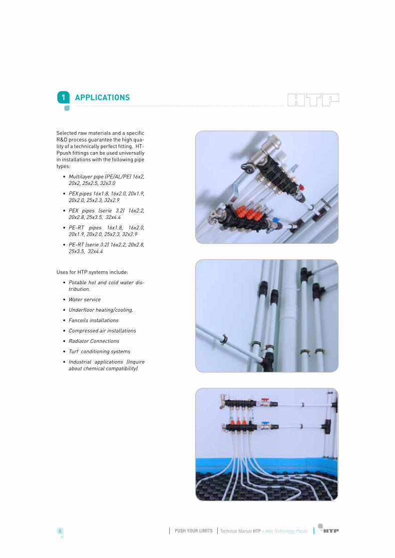
Selected raw materials and a specific R&D process guarantee the high qua-lity of a technically perfect fitting. HT-Ppush fittings can be used universally in installations with the following pipe types:
• Multilayer pipe (PE/AL/PE) 16x2, 20x2, 25x2.5, 32x3.0
• PEX pipes 16x1.8, 16x2.0, 20x1.9, 20x2.0, 25x2.3, 32x2.9
• PEX pipes (serie 3.2) 16x2.2, 20x2.8, 25x3.5, 32x4.4
• PE-RT pipes 16x1.8, 16x2.0, 20x1.9, 20x2.0, 25x2.3, 32x2.9
• PE-RT (serie 3.2) 16x2.2, 20x2.8, 25x3.5, 32x4.4
Uses for HTP systems include:
• Potable hot and cold water dis-tribution.
• Water service
• Underfloor heating/cooling.
• Fancoils installations
• Compressed air installations
• Radiator Connections
• Turf conditioning systems
• Industrial applications (Inquire about chemical compatibility)
1 APPLICATIONS
6 7Technical Manual HTP – Hita Technology Plastic Technical Manual HTP – Hita Technology PlasticPUSH YOUR LIMITS PUSH YOUR LIMITS
• Stock reduction.
50 % reduction of the fittings stock needed as compared to traditional systems, compatible both with different types of pipes specified before.
• High pressure and temperature resistant.
HTPpush fitting is ideally suited for systems operating up to 120 ºC, as well as an operating pres-sure of 40 bar guarantees high safety for the daily use.
• No corrosion.
Scale and corrosion simply can-not build-up inside either HTP systems thanks to the smooth inner surface of the system and chemical resistance.
• Light –weight.
The system is not only flexible, but also very light weight. Sim-ple and fast installation saves time and money.
• Health.
All system components com-ply with the most strict toxico-logical and hygienic standards (SSI/304/203, RD140:2003, KTW, W270, WRAS…) that makes the system suitable for transporting drinking water.
• Simple assembling.
The pipe/fitting connection can be done within seconds without mechanical tools. Scissors and former is only needed.
• Additional watertightness sa-fety.
The fittings have two watertight-ness rings that guarantee the functionality of the system.
2 ADVANTAGES OF THE HTPpush SYSTEM
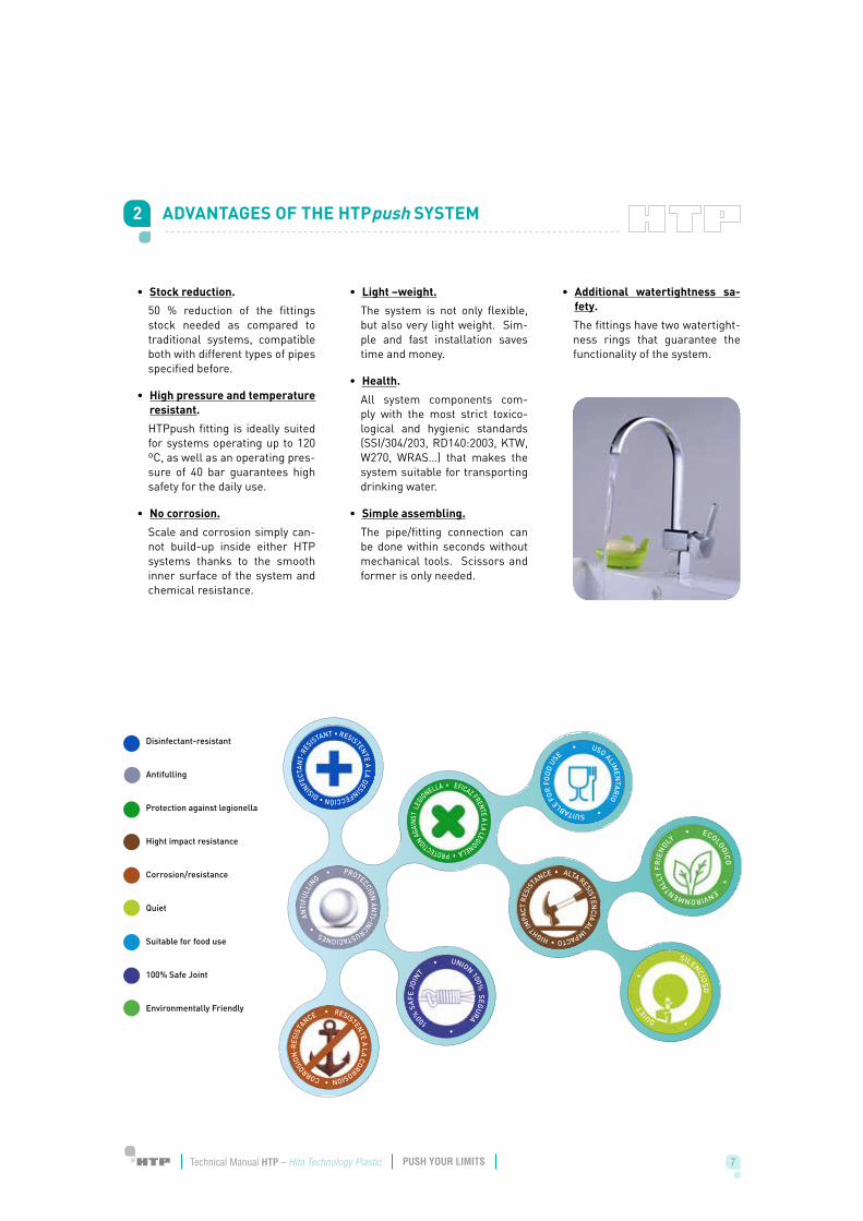
Disinfectant-resistant
Antifulling
Protection against legionella
Hight impact resistance
Corrosion/resistance
Quiet
Suitable for food use
100% Safe Joint
Environmentally Friendly
RESISTENTE A LA DESINFECCIÓN • DISINFE
CTAN
T-RE
SISTANT •
EFICAZ FRENTE A LA LEGIONELA • PROTECTION AGAI
NST
LEGIONELLA •
ALTA RESISTENCIA AL IMPACTO • HIGHT IM
PACT
RES
ISTA
NCE •
UNION 100% SEGURA •
100% S
AFE
JOIN
T •
RESISTENTE A LA CORROSION • CORROSION
-RES
ISTA
NCE •
PROTECCION AN
TI-INCRUSTACIONES •
AN
TIFU
LLIN
G •
USO ALIMEN
TARIO • SUITABLE FOR
FO
OD
USE •
ECOLOGICO
• ENVIRONMENTALLY
FR
IEN
DLY •
SILENCIOSO
• QUIE
T
•
8 9Technical Manual HTP – Hita Technology Plastic Technical Manual HTP – Hita Technology PlasticPUSH YOUR LIMITS PUSH YOUR LIMITS
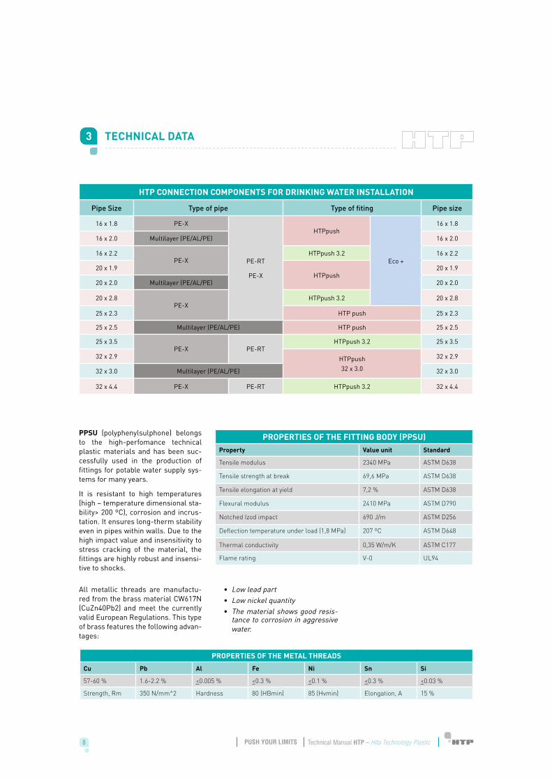
PPSU (polyphenylsulphone) belongs to the high-perfomance technical plastic materials and has been suc-cessfully used in the production of fittings for potable water supply sys-tems for many years.
It is resistant to high temperatures (high – temperature dimensional sta-bility> 200 ºC), corrosion and incrus-tation. It ensures long-therm stability even in pipes within walls. Due to the high impact value and insensitivity to stress cracking of the material, the fittings are highly robust and insensi-tive to shocks.
3 TECHNICAL DATA
HTP CONNECTION COMPONENTS FOR DRINKING WATER INSTALLATION
Pipe Size Type of pipe Type of fiting Pipe size
16 x 1.8 PE-X
PE-RT
PE-X
HTPpush
Eco +
16 x 1.8
16 x 2.0 Multilayer (PE/AL/PE) 16 x 2.0
16 x 2.2PE-X
HTPpush 3.2 16 x 2.2
20 x 1.9HTPpush
20 x 1.9
20 x 2.0 Multilayer (PE/AL/PE) 20 x 2.0
20 x 2.8PE-X
HTPpush 3.2 20 x 2.8
25 x 2.3 HTP push 25 x 2.3
25 x 2.5 Multilayer (PE/AL/PE) HTP push 25 x 2.5
25 x 3.5PE-X PE-RT
HTPpush 3.2 25 x 3.5
32 x 2.9 HTPpush32 x 3.0
32 x 2.9
32 x 3.0 Multilayer (PE/AL/PE) 32 x 3.0
32 x 4.4 PE-X PE-RT HTPpush 3.2 32 x 4.4
PROPERTIES OF THE FITTING BODY (PPSU)Property Value unit Standard
Tensile modulus 2340 MPa ASTM D638
Tensile strength at break 69,6 MPa ASTM D638
Tensile elongation at yield 7,2 % ASTM D638
Flexural modulus 2410 MPa ASTM D790
Notched Izod impact 690 J/m ASTM D256
Deflection temperature under load (1,8 MPa) 207 ºC ASTM D648
Thermal conductivity 0,35 W/m/K ASTM C177
Flame rating V-0 UL94
PROPERTIES OF THE METAL THREADS
Cu Pb Al Fe Ni Sn Si
57-60 % 1.6-2.2 % <0.005 % <0.3 % <0.1 % <0.3 % <0.03 %
Strength, Rm 350 N/mm^2 Hardness 80 (HBmin) 85 (Hvmin) Elongation, A 15 %
All metallic threads are manufactu-red from the brass material CW617N (CuZn40Pb2) and meet the currently valid European Regulations. This type of brass features the following advan-tages:
• Low lead part• Low nickel quantity• The material shows good resis-
tance to corrosion in aggressive water.
8 9Technical Manual HTP – Hita Technology Plastic Technical Manual HTP – Hita Technology PlasticPUSH YOUR LIMITS PUSH YOUR LIMITS
Poliphenylsulfone (PPSU), raw mate-rial of HTPpush fittings, generally is resistant to attack from many chemi-cals which make it suitable for use in many process applications. PPSU is inert to most acids, bases, salts and a variety of organic media, with certain limits of concentration and tempera-ture. Consequently:
• HTPpush fittings are used not only for drinking water, water for general use but also for the con-veyance of aggressive liquids.
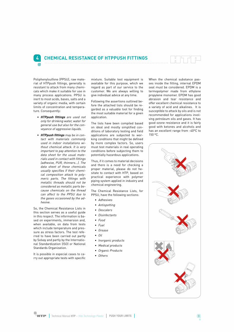
• HTPpush fittings may be in con-tact with materials commonly used in indoor installations wi-thout chemical attack. It is very important to pay attention to the data sheet for the usual mate-rials used in contact with fittings (adhesive, PUR, thinners…). The data sheet of these chemicals usually specifies if their chemi-cal composition attack to poly-meric parts. The fittings with metallic threads should not be considered as metallic parts be-cause chemicals on the thread can affect to the PPSU due to the gases occasioned by the ad-hesive.
So, the Chemical Resistance Lists in this section serves as a useful guide in this respect. The information is ba-sed on experiments, immersion and, when available, on data from tests which include temperature and pres-sure as stress factors. The test refe-rred to have been carried out partly by Solvay and partly by the Internatio-nal Standardization (ISO) or National Standards Organization.
It is possible in especial cases to ca-rry out appropriate tests with specific
mixture. Suitable test equipment is available for this purpose, which we regard as part of our service to the customer. We are always willing to give individual advice at any time.
Following the assertions outlined be-fore the attached lists should be re-garded as a valuable tool for finding the most suitable material for a given application.
The lists have been compiled based on ideal and mostly simplified con-ditions of laboratory testing and field applications are subjected to wor-king conditions that might be defined by more complex factors. So, users must test materials in real operating conditions before subjecting them to potentially hazardous applications.
Thus, if it comes to material decisions and there is a need for checking a proper material, please do not he-sitate to contact with HTP, based on practical experience with polymer piping system applied in industry and chemical engineering.
The Chemical Resistance Lists, for PPSU, have the following sections:
• Adhesives• Antispotting • Descalers• Disinfectants• Food • Fuel• Grease• Oil• Inorganic products• Medical products• Organic Products• Others
When the chemical substance pas-ses inside the fitting, internal EPDM seal must be considered. EPDM is a termopolymer made from ethylene propylene monomer. EPDM has good abrasion and tear resistance and offer excellent chemical resistance to a variety of acid and alkalines. It is susceptible to attack by oils and is not recommended for applications invol-ving petroleum oils and gases. It has good ozone resistance and it is fairly good with ketones and alcohols and has an excellent range from -40ºC to 150 ºC.
4 CHEMICAL RESISTANCE OF HTPPUSH FITTINGS
10 11Technical Manual HTP – Hita Technology Plastic Technical Manual HTP – Hita Technology PlasticPUSH YOUR LIMITS PUSH YOUR LIMITS10 11Technical Manual HTP – Hita Technology Plastic Technical Manual HTP – Hita Technology PlasticPUSH YOUR LIMITS PUSH YOUR LIMITS
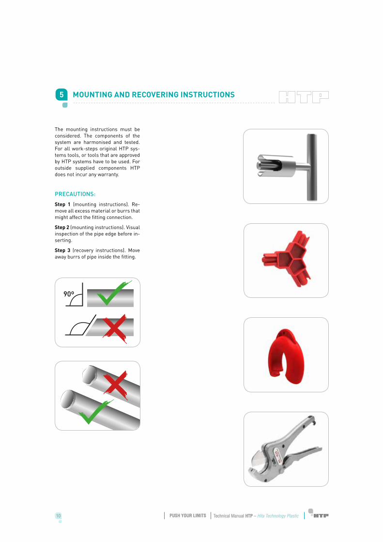
The mounting instructions must be considered. The components of the system are harmonised and tested. For all work-steps original HTP sys-tems tools, or tools that are approved by HTP systems have to be used. For outside supplied components HTP does not incur any warranty.
PRECAUTIONS:
Step 1 (mounting instructions). Re-move all excess material or burrs that might affect the fitting connection.
Step 2 (mounting instructions). Visual inspection of the pipe edge before in-serting.
Step 3 (recovery instructions). Move away burrs of pipe inside the fitting.
5 MOUNTING AND RECOVERING INSTRUCTIONS
90º
10 11Technical Manual HTP – Hita Technology Plastic Technical Manual HTP – Hita Technology PlasticPUSH YOUR LIMITS PUSH YOUR LIMITS10 11Technical Manual HTP – Hita Technology Plastic Technical Manual HTP – Hita Technology PlasticPUSH YOUR LIMITS PUSH YOUR LIMITS
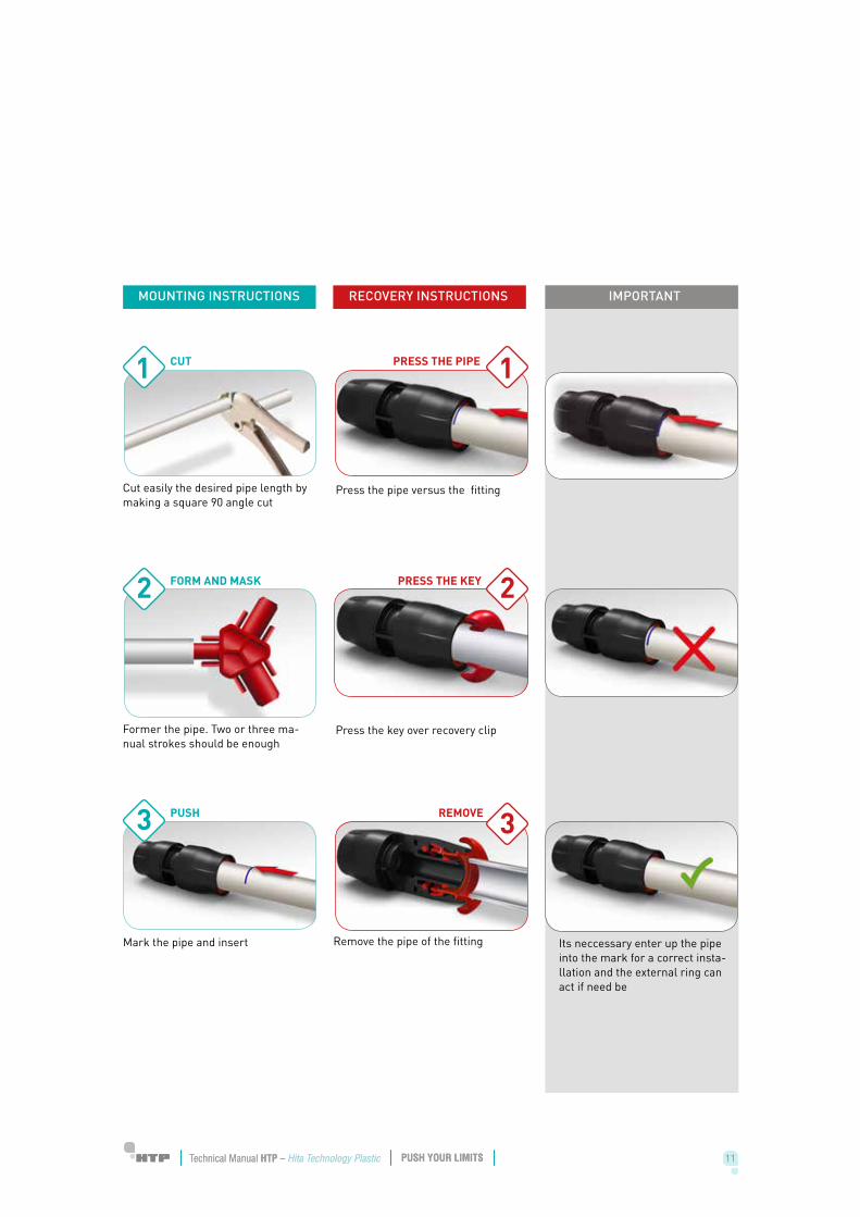
Its neccessary enter up the pipe into the mark for a correct insta-llation and the external ring can act if need be
Remove the pipe of the fittingMark the pipe and insert
MOUNTING INSTRUCTIONS RECOVERY INSTRUCTIONS IMPORTANT
PUSH REMOVE
Press the pipe versus the fittingCut easily the desired pipe length by making a square 90 angle cut
CUT PRESS THE PIPE1 1
3
Press the key over recovery clipFormer the pipe. Two or three ma-nual strokes should be enough
FORM AND MASK PRESS THE KEY 22
3
12 13Technical Manual HTP – Hita Technology Plastic Technical Manual HTP – Hita Technology PlasticPUSH YOUR LIMITS PUSH YOUR LIMITS12 13Technical Manual HTP – Hita Technology Plastic Technical Manual HTP – Hita Technology PlasticPUSH YOUR LIMITS PUSH YOUR LIMITS
6 INSTALLATION REGULATION
6.1 GENERAL INSTRUCTIONS
Observe the applicable national and international regulation on installa-tion, accident prevention and safety when installing piping systems, as well as the instructions in this Tech-nical Information.
Also observe the applicable laws, standards, guidelines and regulations (e.j. DIN, EN, ISO…) as well as regu-lations on environmental protection, provisions of professional associa-tions and regulations of the local pu-blic utility Companies.
The applicable technical regulation, standards and guidelines have to be observed during the installation of heating and potable water. Technical building Code (CTE, HS4) must be ac-complished in installations done in Spain.
Areas of application not contained in this Technical Information (special applications) require consultation with HTP. For detailed advice, please contact the HTP Technical Depart-ment. Installation must only be ca-rried out by specialists.
When using HTPpush system, the following instructions have to be observed:
1. For threaded connections, HTP recommends the use of sealing wire that meets the requirements of EN 751-2. If liquids thread sealants are used, it is very important to pay attention to its data sheet and to be sure about chemical compatibility.
2. Prevention of air locks. Pipes runs must be laid so that no air locks are possible. At the lowest point in the system, there must also be a way of draining the pipeline.
3. Protection against uv irradiation. Exposure to UV irradiation over an ex-tended period will damage the HTPpush system. For this reason, the pipes and fittings should not be stored outdoors. If necessary, they must protec-ted against UV-light.
4. Pipework may be laid in the ground (when the applicable national regula-tion allows it) under the following conditions:
• The pipes must be laid in a bed of sand.• The pipes must be covered with fine-grain sand to such an extent that
there is no danger of damage to the pipe when the later fill material is applied.
• There must be no moveable loads affecting the pipes laid in the ground.• The fittings and the pressure sleeves must be protected against direct
contact with the ground by a suitable corrosion protection agent.
5. Contact with solvents. Direct contact of HTPpush components with sol-vents or solvent containing varnishes, paints, greases, sprays, adhesive strips, etc. must be prevented. The solvents can attack the plastic compo-nents of the system.
6. Protection against frost. Filled HTPpush system must be protected against frost. The system is suitable for the following antifreeze agents and concentrations:
• Ethylene glycol (antifrozen N). May be used up to a concentration of 50 % maximum. This concentration is equivalent is equivalent to frost protection down to a temperature of 38 ºC.
• Propylene glycol. May be used up to a maximum concentration of 25%. It is used primarily by the food processing industry. A concentration of 25% provides frost protection down to 10 ºC.
• At higher concentration of both products, stress crack may occur in the system.
12 13Technical Manual HTP – Hita Technology Plastic Technical Manual HTP – Hita Technology PlasticPUSH YOUR LIMITS PUSH YOUR LIMITS12 13Technical Manual HTP – Hita Technology Plastic Technical Manual HTP – Hita Technology PlasticPUSH YOUR LIMITS PUSH YOUR LIMITS
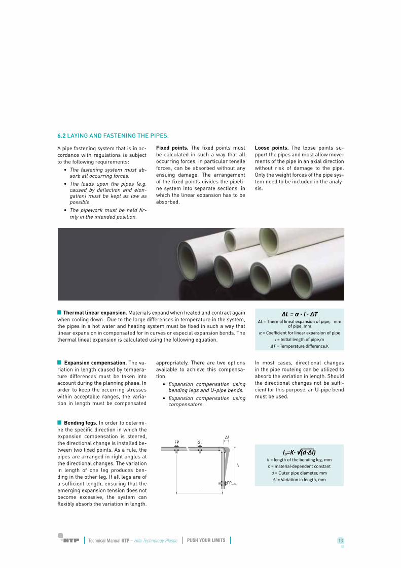
A pipe fastening system that is in ac-cordance with regulations is subject to the following requirements:
• The fastening system must ab-sorb all occurring forces.
• The loads upon the pipes (e.g. caused by deflection and elon-gation) must be kept as low as possible.
• The pipework must be held fir-mly in the intended position.
Fixed points. The fixed points must be calculated in such a way that all occurring forces, in particular tensile forces, can be absorbed without any ensuing damage. The arrangement of the fixed points divides the pipeli-ne system into separate sections, in which the linear expansion has to be absorbed.
Loose points. The loose points su-pport the pipes and must allow move-ments of the pipe in an axial direction without risk of damage to the pipe. Only the weight forces of the pipe sys-tem need to be included in the analy-sis.
∆L = α ∙ l ∙ ∆T∆L = Thermal lineal expansion of pipe, mm
of pipe, mmα = Coefficient for linear expansion of pipe
l = Initial length of pipe,m∆T = Temperature difference,K
Thermal linear expansion. Materials expand when heated and contract again when cooling down . Due to the large differences in temperature in the system, the pipes in a hot water and heating system must be fixed in such a way that linear expansion in compensated for in curves or especial expansion bends. The thermal lineal expansion is calculated using the following equation.
Expansion compensation. The va-riation in length caused by tempera-ture differences must be taken into account during the planning phase. In order to keep the occurring stresses within acceptable ranges, the varia-tion in length must be compensated
appropriately. There are two options available to achieve this compensa-tion:
• Expansion compensation using bending legs and U-pipe bends.
• Expansion compensation using compensators.
In most cases, directional changes in the pipe routeing can be utilized to absorb the variation in length. Should the directional changes not be suffi-cient for this purpose, an U-pipe bend must be used.
lB=K∙ √(d∙∆l)lB = length of the bending leg, mmK = material-dependent constant
d = Outer pipe diameter, mm∆l = Variation in length, mm
Bending legs. In order to determi-ne the specific direction in which the expansion compensation is steered, the directional change is installed be-tween two fixed points. As a rule, the pipes are arranged in right angles at the directional changes. The variation in length of one leg produces ben-ding in the other leg. If all legs are of a sufficient length, ensuring that the emerging expansion tension does not become excessive, the system can flexibly absorb the variation in length.
6.2 LAYING AND FASTENING THE PIPES.
14 15Technical Manual HTP – Hita Technology Plastic Technical Manual HTP – Hita Technology PlasticPUSH YOUR LIMITS PUSH YOUR LIMITS14 15Technical Manual HTP – Hita Technology Plastic Technical Manual HTP – Hita Technology PlasticPUSH YOUR LIMITS PUSH YOUR LIMITS
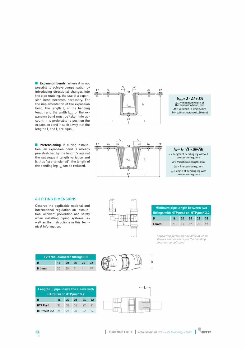
Pretensioning. If, during installa-tion, an expansion bend is already pre-stretched by the length V against the subsequent length variation and is thus “pre-tensioned”, the length of the bending leg lBV can be reduced.
lBV = lB∙ √1 - ∆lv/∆l lB = llength of bending leg without
pre-tensioning, mm∆l = Variation in length, mm
∆lv = Pre-tensioning, mmlBV = length of bending leg with
pre-tensioning, mm
Expansion bends. Where it is not possible to achieve compensation by introducing directional changes into the pipe routeing, the use of a expan-sion bend becomes necessary. For the implementation of the expansion bend, the length lB of the bending length and the width bmin of the ex-pansion bend must be taken into ac-count. It is preferable to position the expansion bend in such a way that the lengths l1 and l2 are equal.
bmin = 2 ∙ ∆l + SAbmin = minimum width of the expansion bend, mm
∆l = Variation in length, mmSA= safety clearance (150 mm)
6.3 FITING DIMENSIONS
Observe the applicable national and international regulation on installa-tion, accident prevention and safety when installing piping systems, as well as the instructions in this Tech-nical Information.
Minimum pipe length between two fittings with HTPpush or HTPpush 3.2
Ø 16 20 25 26 32
L (mm) 75 81 87 73 97
Length (L) pipe inside the sleeve with HTPpush or HTPpush 3.2
Ø 16 20 25 26 32
HTPPush 30 33 36 29 41
HTPPush 3.2 25 27 30 22 34
Recovering partes may be difficult when sleeves are neas because the handling becomes complicated
External diameter fittings (D)
Ø 16 20 25 26 32
D (mm) 30 35 41 41 49
D
L
14 15Technical Manual HTP – Hita Technology Plastic Technical Manual HTP – Hita Technology PlasticPUSH YOUR LIMITS PUSH YOUR LIMITS14 15Technical Manual HTP – Hita Technology Plastic Technical Manual HTP – Hita Technology PlasticPUSH YOUR LIMITS PUSH YOUR LIMITS
The HTPpush fitting is highly regu-lated. Standards, specifications and code requirements define tight ma-terial and production quality controls.
Continous-use temperature rating as high as 95 ºC are required to ensure that the system withstand the most aggressive drinking water condi-tions. Nationally and internationally accredited, the Certification Agencies require strenuous quality control tes-ting, including random plants inspec-tions and annual monitoring testing.
The HTPpush fitting meets the requi-rements of the following standards:
« ISO 21003: Multilayer piping sys-tems for hot and cold water installa-tion inside buildings.
« ISO 15875: Plastic piping system for hot and cold water installations- crosslinked polyethylene (PE-X).
« ISO 22391: Plastics piping systems for hot and cold water installations. Poliethylene of raised temperature resistance (PE-RT).
« RD2006/2008. In relation to Com-pressed air installations. Spanish regulations of pressure application equipments.
« W270 DVGW (related to raw ma-terial). Vermehrung von Mikroor-ganismen aut Werkstoffen für den Trinkwasserbereich-Prüfung und Bewertung.
« KTW-LEITLINIE (related to raw material). Leitlinie zur hygienischen Beurteilung von organischen Mate-rialien im Kontakt mit Trinkwasser.
« 4MS COMON APPROACH (related to metallic threads). Acceptance of metallic materials used for products in contact with drinking water.
« EN 681 (related to internal rings). Elastomeric seals. Material requi-rements for pipe joint seals in water and drainage applications.
« 98/83/CE. Quality of water inten-ded for human consumption.
« ENV 12108. Plastics piping sys-tems. Guidance for the installation inside buildings of pressure systems for hot and cold water intended for human consumption.
7 STANDARDS
16 17Technical Manual HTP – Hita Technology Plastic Technical Manual HTP – Hita Technology PlasticPUSH YOUR LIMITS PUSH YOUR LIMITS16 17Technical Manual HTP – Hita Technology Plastic Technical Manual HTP – Hita Technology PlasticPUSH YOUR LIMITS PUSH YOUR LIMITS
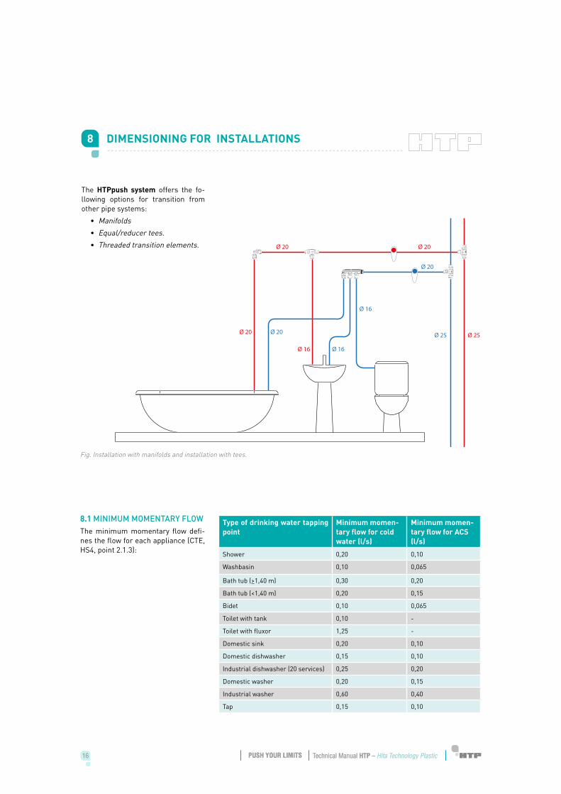
Fig. Installation with manifolds and installation with tees.
8 DIMENSIONING FOR INSTALLATIONS
The HTPpush system offers the fo-llowing options for transition from other pipe systems:
• Manifolds• Equal/reducer tees.• Threaded transition elements.
Type of drinking water tapping point
Minimum momen-tary flow for cold water (l/s)
Minimum momen-tary flow for ACS (l/s)
Shower 0,20 0,10
Washbasin 0,10 0,065
Bath tub (>1,40 m) 0,30 0,20
Bath tub (<1,40 m) 0,20 0,15
Bidet 0,10 0,065
Toilet with tank 0,10 -
Toilet with fluxor 1,25 -
Domestic sink 0,20 0,10
Domestic dishwasher 0,15 0,10
Industrial dishwasher (20 services) 0,25 0,20
Domestic washer 0,20 0,15
Industrial washer 0,60 0,40
Tap 0,15 0,10
8.1 MINIMUM MOMENTARY FLOWThe minimum momentary flow defi-nes the flow for each appliance (CTE, HS4, point 2.1.3):
Ø 20
Ø 20Ø 20
Ø 20
Ø 20
Ø 25 Ø 25
Ø 16
Ø 16Ø 16
16 17Technical Manual HTP – Hita Technology Plastic Technical Manual HTP – Hita Technology PlasticPUSH YOUR LIMITS PUSH YOUR LIMITS16 17Technical Manual HTP – Hita Technology Plastic Technical Manual HTP – Hita Technology PlasticPUSH YOUR LIMITS PUSH YOUR LIMITS
Section in consideration Nominal diameter of the source’s pipe
Source to private wet room: bathroom, kitchen.
20
Source to individual branches: apart-ments, commercial local…
20
Column (posts and descendants) 20
Main distributor 25
<50 kW 12
50-250 kW 20
Source to climate control equipments -
250-500 kW 25
>500 KW 32
8.2 MAXIMUM AND MINIMUM PRESSUREThe minimum dynamic pressure in all consumption points, and used to cal-culate the simultaneous flow, must be:
• 100 kPa in the case of taps.• 150 kPa in the case of fluxors
and boilers.
The pressure must be lower than 500 kPa in each consumption point.
8.4 MINIMUM NOMINAL DIAME-TER OF SOURCE
The minimum nominal diameters of source, according to HS4 4.3, are the following:
Type of drinking water tapping point
Minimum diameter (*) of the connec-tion branch (mm)
Shower 12
Washbasin 12
Bath tub (>1,40 m) 20
Bath tub (<1,40 m) 20
Bidet 12
Toilet with tank 12
Toilet with fluxor 25-40
Domestic sink 12
Domestic dishwasher 12
Industrial dishwasher (20 services) 20
Domestic washer 20
Industrial washer 25 (*) Cupper or plastic pipe.
8.3 MINIMUM NOMINAL DIA-METER OF DERIVATION TO APPLIANCES
The minimum diameters are related to external diameters, according to UNE-EN ISO 15875. The minimum nominal diameters to connect pipes to appliances are showed in the Buil-ding Technical Code (HS4, point 4.3) as follow:
18 19Technical Manual HTP – Hita Technology Plastic Technical Manual HTP – Hita Technology PlasticPUSH YOUR LIMITS PUSH YOUR LIMITS
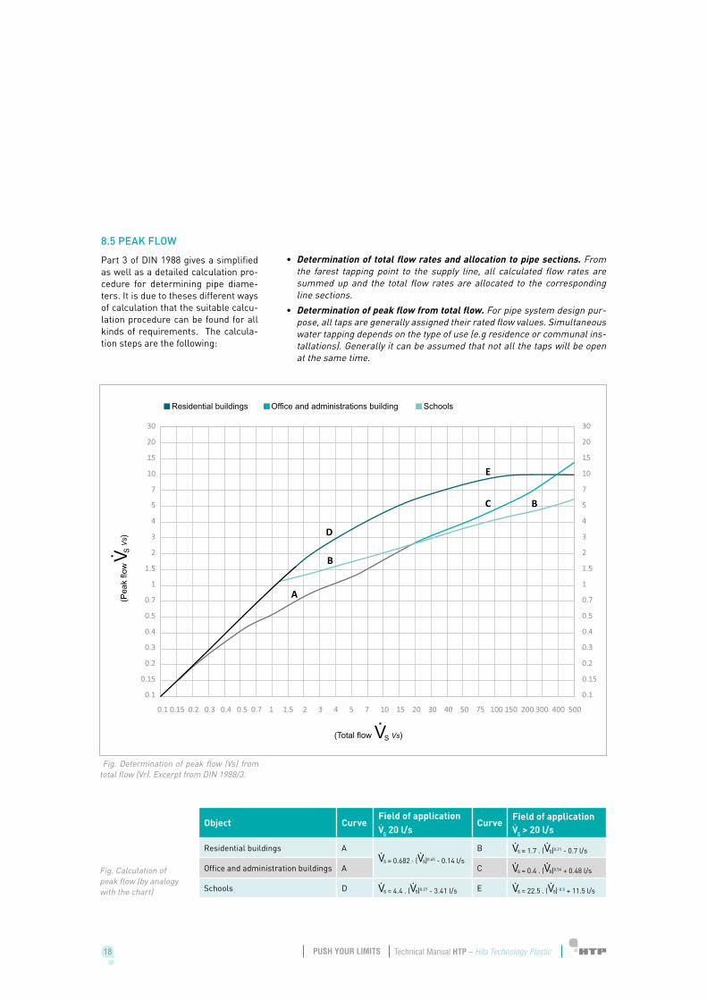
8.5 PEAK FLOW
Part 3 of DIN 1988 gives a simplified as well as a detailed calculation pro-cedure for determining pipe diame-ters. It is due to theses different ways of calculation that the suitable calcu-lation procedure can be found for all kinds of requirements. The calcula-tion steps are the following:
• Determination of total flow rates and allocation to pipe sections. From the farest tapping point to the supply line, all calculated flow rates are summed up and the total flow rates are allocated to the corresponding line sections.
• Determination of peak flow from total flow. For pipe system design pur-pose, all taps are generally assigned their rated flow values. Simultaneous water tapping depends on the type of use (e.g residence or communal ins-tallations). Generally it can be assumed that not all the taps will be open at the same time.
Fig. Determination of peak flow (Vs) from total flow (Vr). Excerpt from DIN 1988/3.
Fig. Calculation of peak flow (by analogy with the chart)
Object CurveField of applicationVS 20 l/s
CurveField of applicationVS > 20 l/s
Residential buildings A = 0.682 · ( )0.45 - 0.14 l/s
B = 1.7 . ( )0.21 - 0.7 l/s
Office and administration buildings A C = 0.4 . ( )0.54 + 0.48 l/s
Schools D = 4.4 . ( )0.27 - 3.41 l/s E = 22.5 . ( )-0.5 + 11.5 l/s
18 19Technical Manual HTP – Hita Technology Plastic Technical Manual HTP – Hita Technology PlasticPUSH YOUR LIMITS PUSH YOUR LIMITS
8.6 FLOW RATES
For sound insulation reasons and in order to limit water hammer, the cal-culated flow rate value must not ex-ceed the following values ( HS4, point 4.2.1).
• Metallic pipes: 0.5-2.0 m/s• Thermoplastic and multilayer
pipes: 0.5-3.5 m/s
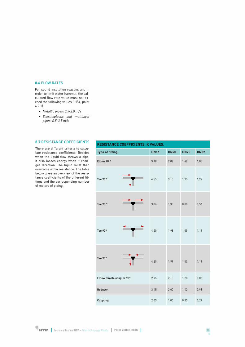
8.7 RESISTANCE COEFFICIENTS
There are different criteria to calcu-late resistance coefficients. Besides when the liquid flow throws a pipe, it also looses energy when it chan-ges direction. The liquid must then overcome extra resistance. The table below gives an overview of the resis-tance coefficients of the different fit-tings and the corresponding number of meters of piping.
RESISTANCE COEFFICIENTS. K VALUES.
Type of fitting DN16 DN20 DN25 DN32
Elbow 90 º 3,48 2,02 1,42 1,03
Tee 90 º 4,55 3,15 1,75 1,22
Tee 90 º 3,06 1,33 0,88 0,56
Tee 90º 4,20 1,98 1,55 1,11
Tee 90º4,20 1,99 1,55 1,11
Elbow female adapter 90º 2,75 2,10 1,28 0,05
Reducer 3,45 2,00 1,42 0,98
Coupling 2,05 1,00 0,35 0,27
20 21Technical Manual HTP – Hita Technology Plastic Technical Manual HTP – Hita Technology PlasticPUSH YOUR LIMITS PUSH YOUR LIMITS20 21Technical Manual HTP – Hita Technology Plastic Technical Manual HTP – Hita Technology PlasticPUSH YOUR LIMITS PUSH YOUR LIMITS
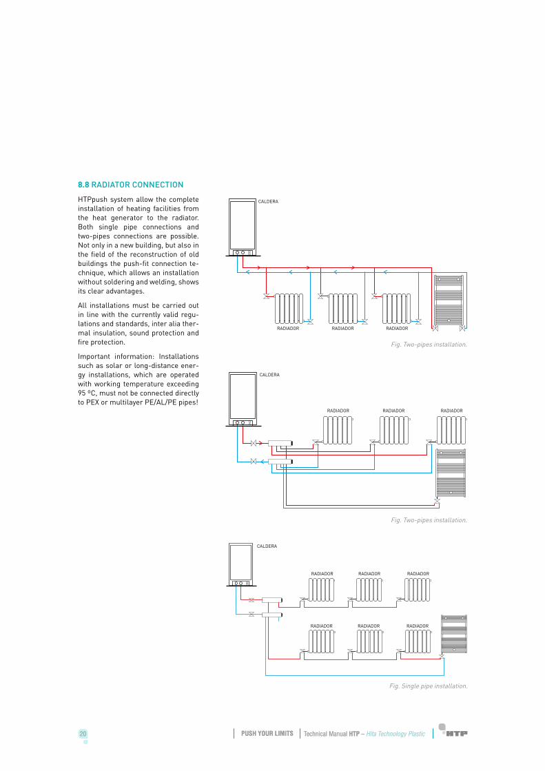
8.8 RADIATOR CONNECTION
HTPpush system allow the complete installation of heating facilities from the heat generator to the radiator. Both single pipe connections and two-pipes connections are possible. Not only in a new building, but also in the field of the reconstruction of old buildings the push-fit connection te-chnique, which allows an installation without soldering and welding, shows its clear advantages.
All installations must be carried out in line with the currently valid regu-lations and standards, inter alia ther-mal insulation, sound protection and fire protection.
Important information: Installations such as solar or long-distance ener-gy installations, which are operated with working temperature exceeding 95 ºC, must not be connected directly to PEX or multilayer PE/AL/PE pipes!
Fig. Two-pipes installation.
CALDERA
RADIADOR RADIADOR RADIADOR
Fig. Two-pipes installation.
CALDERA
RADIADOR RADIADOR RADIADOR
Fig. Single pipe installation.
CALDERA
RADIADOR
RADIADOR
RADIADOR
RADIADOR
RADIADOR
RADIADOR
20 21Technical Manual HTP – Hita Technology Plastic Technical Manual HTP – Hita Technology PlasticPUSH YOUR LIMITS PUSH YOUR LIMITS20 21Technical Manual HTP – Hita Technology Plastic Technical Manual HTP – Hita Technology PlasticPUSH YOUR LIMITS PUSH YOUR LIMITS
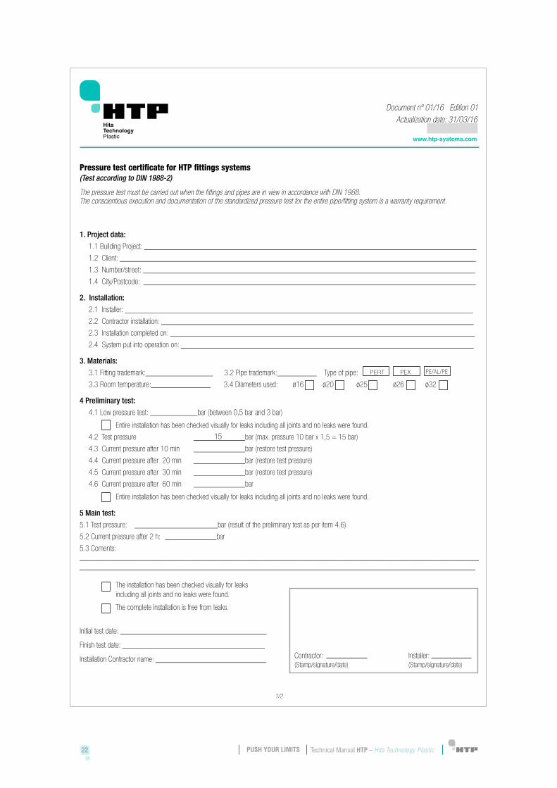
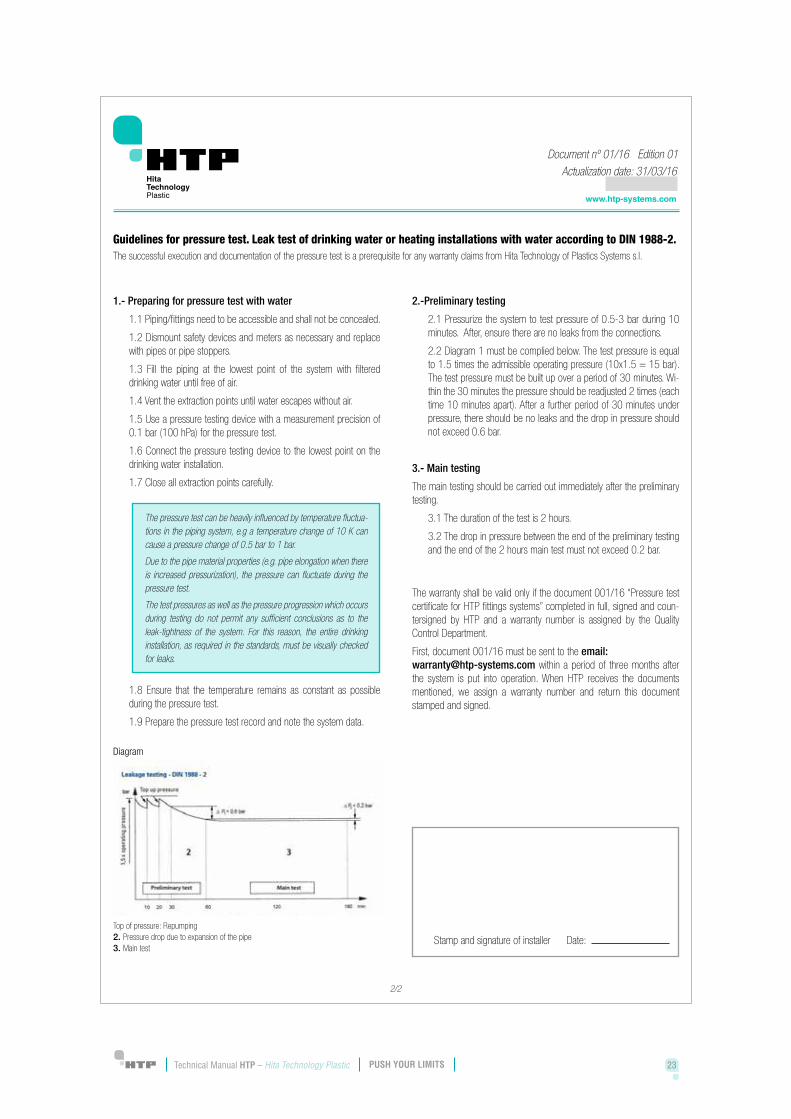
According to DIN 1988, for HTP sys-tems a pressure test has to be ca-rried out in an uncovered state after finishing. Each connection has to be checked visually for the correct pres-sing.
Document 001/16 must be sent to the email [email protected] within a period of three months after the system is put into operation.
9 HYDRAULIC PRESSURE TEST
22 23Technical Manual HTP – Hita Technology Plastic Technical Manual HTP – Hita Technology PlasticPUSH YOUR LIMITS PUSH YOUR LIMITS
22 23Technical Manual HTP – Hita Technology Plastic Technical Manual HTP – Hita Technology PlasticPUSH YOUR LIMITS PUSH YOUR LIMITS
24 25Technical Manual HTP – Hita Technology Plastic Technical Manual HTP – Hita Technology PlasticPUSH YOUR LIMITS PUSH YOUR LIMITS24 25Technical Manual HTP – Hita Technology Plastic Technical Manual HTP – Hita Technology PlasticPUSH YOUR LIMITS PUSH YOUR LIMITS
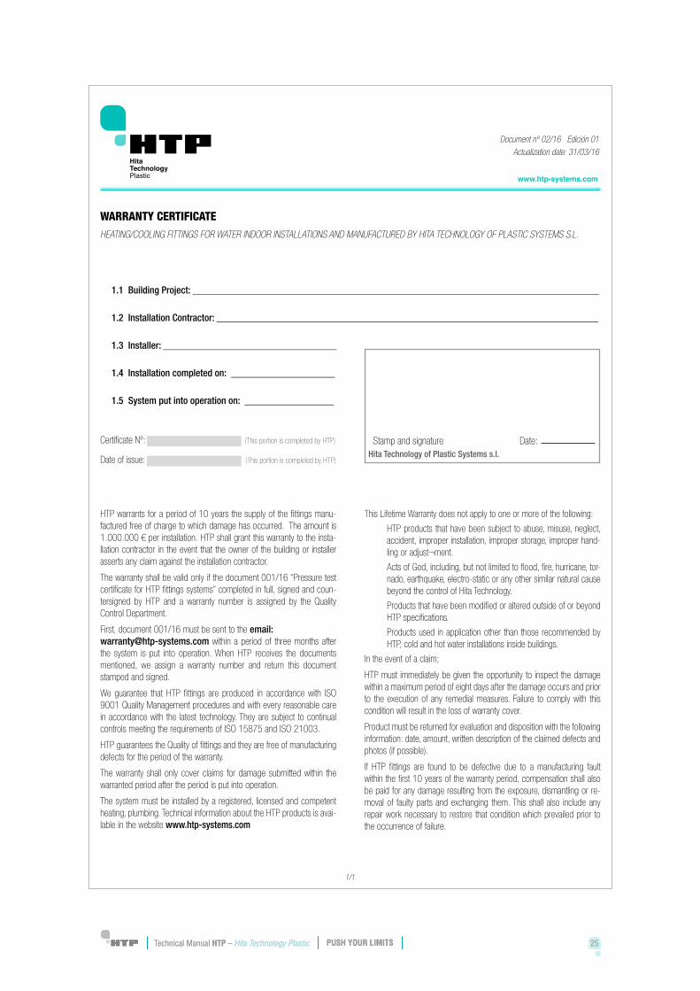
HTP warrants for a period of 10 years the supply of the fittings manufac-tured free of charge to which da-mage has occurred. The amount is 1.000.000 € per installation.
The warranty shall be valid only if the document 001/16 “pressure test cer-tificate for HTP systems” completed in full, signed and countersigned by HTP and a warranty number is as-signed by the Quality Control Depart-ment.
10 WARRANTY
24 25Technical Manual HTP – Hita Technology Plastic Technical Manual HTP – Hita Technology PlasticPUSH YOUR LIMITS PUSH YOUR LIMITS24 25Technical Manual HTP – Hita Technology Plastic Technical Manual HTP – Hita Technology PlasticPUSH YOUR LIMITS PUSH YOUR LIMITS
26 27Technical Manual HTP – Hita Technology Plastic Technical Manual HTP – Hita Technology PlasticPUSH YOUR LIMITS PUSH YOUR LIMITS26 27Technical Manual HTP – Hita Technology Plastic Technical Manual HTP – Hita Technology PlasticPUSH YOUR LIMITS PUSH YOUR LIMITS
HTP Systems selected for the EU framework programme for research and innovation
Hita Technology of Plastic Systems is proud to be selected into the group of 78 European companies, and 12 Spa-nish only, like deserving of finance innovation activities and the develo-pment by the European commission throw to SME instrument Phase II program.
Our innovative project, HTPush, have been chosen into NMP25-2015 cate-gory, focused on technology materials and nanomaterials being the only Spanish project in this category.
We are also the unique Andalusian Company deserve such recognition and awarded with this European aid.
Our Project focuses on new deve-lopment and materials research to change the construction methods, supporting technological innovation and material research also taking into account project and client offe-ring products for fluid conduction make it totally in technical plastics materials. Giving to sector the chance to invest in technology and research resulting in faster, better and safer installations.
More info about The SME Instrument:
https://ec.europa.eu/programmes/horizon2020/en/h2020-section/sme-instrument
11 HORIZON 2020

26 27Technical Manual HTP – Hita Technology Plastic Technical Manual HTP – Hita Technology PlasticPUSH YOUR LIMITS PUSH YOUR LIMITS26 27Technical Manual HTP – Hita Technology Plastic Technical Manual HTP – Hita Technology PlasticPUSH YOUR LIMITS PUSH YOUR LIMITS

28 29Technical Manual HTP – Hita Technology Plastic Technical Manual HTP – Hita Technology PlasticPUSH YOUR LIMITS PUSH YOUR LIMITS

28 29Technical Manual HTP – Hita Technology Plastic Technical Manual HTP – Hita Technology PlasticPUSH YOUR LIMITS PUSH YOUR LIMITS