Embed Size (px)
Citation preview


Hüseyin ŞehitoğluC.J.Gauthier Professor and Head
University of Illinois, Department of Mechanical Science and Engineering, Urbana, IL,USA Presentation at the International Railway Symposium, December 13-15, Istanbul/Ankara
Freight Railroads- Research from Atoms to StructuresYük Trenleri-Atomik Boyuttan Gerçek Yapılara Uzanan Bir Araştırma

Nomenclature- Terimlendirme
Tension- Çekme GerilimiCompression- Basma GerilimiThermal Stress- Isıl GerilmeStrain- GerinimFatigue Limit- Yorulma SınırıYield Stress- Akma GerilimiStress Concentration- Gerilim YoğunlaşmasıMicrostructure-İçyapıConstraint-KısıtTexture- DokuShear Stress- Makaslama GerilimiSlip-KaymaStick-YapışmaGrinding- Taşlama

Demiryolu Endüstrisinin Önemi

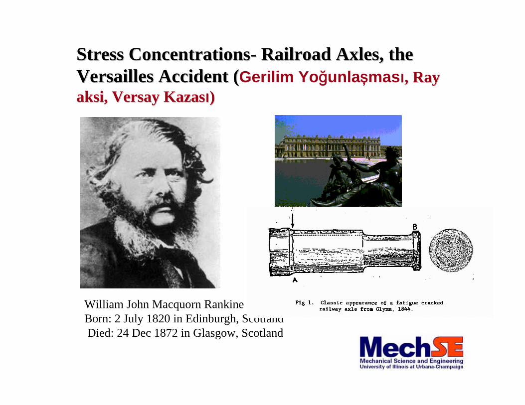
Talk Outline (Konuşma Taslağı)
•Fatigue/Deformation Preliminaries (Yorulma)
•Wheels- Thermo-mechanical Fatigue
(Tekerlekler,Termo-mekanik Yorulma)
•Rails- Ratcheting and Fatigue/Wear
(Raylar- Gerinme ve Aşınma)
•Materials Design- Diamond Crossing
•(Yeni Mazemelerin Atomik Boyutta Tasarımı-Makas Elması)
•Bearings- Cone Bore Growth
(Rulmanlı Yataklar)
•Conclusions (Sonuçlar)
William John Macquorn RankineBorn: 2 July 1820 in Edinburgh, ScotlandDied: 24 Dec 1872 in Glasgow, Scotland
Stress ConcentrationsStress Concentrations-- Railroad Axles, the Railroad Axles, the Versailles Accident (Versailles Accident (Gerilim Yoğunlaşması, Ray , Ray aksiaksi, , VersayVersay KazasKazasıı))

BauschingerBauschinger Effect and the Presentation Effect and the Presentation of the Fatigue Limit (of the Fatigue Limit (BauschingerBauschinger etkisietkisi veve
YorulmaYorulma SSıınnıırrıı))

Early ObservationsEarly Observations(A. Ewing, Humphreys, W. Rosenhain, 1899)- Eski İncelemeler

H. F. Moore’s Book, p.224
(Ray üzerindeİçyapı)

Talk Outline (Konuşma Taslağı)
•Fatigue/Deformation Preliminaries (Yorulma)
•Wheels- Thermo-mechanical Fatigue
(Tekerlekler,Termo-mekanik Yorulma)
•Rails- Ratcheting and Fatigue/Wear
(Raylar- Gerinme ve Aşınma)
•Materials Design- Diamond Crossing
•(Yeni Mazemelerin Atomik Boyutta Tasarımı-Makas Elması)
•Bearings- Cone Bore Growth
(Rulmanlı Yataklar)
•Conclusions (Sonuçlar)

Total Constraint (Tam Kısıtlama)
T
Tot BD A
O
C
E
α (T-To)
σο
σο−
Mechanical Strain
Stre
ss
T
ε net = 0
Sehitoglu, H., "Constraint Effect in Thermo-mechanical Fatigue," ASME Journal of Engineering Materials and Technology,107, 221-226, 1985. Sehitoglu, H., Thermal and Thermo-Mechanical Fatigue of Structural Alloys, Handbook on Fatigue and Fracture, ASM, 19, 527-554, 1996.

Mechanical Strain
-2x10 -3 -3 -3-10 10
.
.
.
..
.
.
..
......
.
..
.. ....
.
2x10 -3-3x10 -3
-100
-200
-300
Stre
ss (M
Pa)
100
200
60 min, 615 C°°
°°
°°°
50 min, 589 C
55 min, 603 C45 min, 572 C
40 min, 552 C35 min, 527 C
°° °
°°
°
°°°
°°
30 min, 497 C25 min, 459 C
20 min, 438 C 15 min, 362 C
10 min, 295 C5 min, 210 C
65 min, 462 C
70 min, 401 C75 min, 354 C80 min, 314 C
85 min, 279 C°°°
°°
°
90 min, 249 C95 min, 223 C
100 min, 200 C110 min, 162 C
120 min, 133 C
122.5 min, 78 C125 min, 24 C
Railroad Wheels under Friction Braking (Tekerlekler ve fren pabuçları kullanımı)

The Stress-strain Response under Total Constraint (Tam kısıtlama)
Hysteresis and Stress-strain Response in Total Constraint

Thermal Block Histories on Steels under Total Constraint (Blok ısı değişmeleri - tam kısıtlama)
Talk Outline (Konuşma Taslağı)
•Fatigue/Deformation Preliminaries (Yorulma)
•Wheels- Thermo-mechanical Fatigue
(Tekerlekler,Termo-mekanik Yorulma)
•Rails- Ratcheting and Fatigue/Wear
(Raylar- Gerinme ve Aşınma)
•Materials Design- Diamond Crossing
•(Yeni Mazemelerin Atomik Boyutta Tasarımı-Makas Elması)
•Bearings- Cone Bore Growth
(Rulmanlı Yataklar)
•Conclusions (Sonuçlar)

Significant Texture ( Orientation) Develops in the MaterialUnder Contact
•Ratcheting strain is accumulated residual shear strain in the direction of motion of rolling instance. For definitions see:•Jiang, Y. and Sehitoglu, H., 1999, AModel for Rolling Contact Failure,Wear, Vol.224, No1., pp.38-49•Sehitoglu, H. and Jiang, Y., 1993, "Residual Stress Analysis in Rolling Contact," Rail Quality and Maintenance for Modern Railway Operation, Kalker et al., Eds., Kluwer Academic Publishers, pp.349-358•Jiang, Y. and Sehitoglu, H., 1996, Rolling Contact Stress Analysis with the Application of a New Plasticity Model,Wear, Vol.191, pp.35-44

DEFINITION OF RATCHETTING : INCREMENT OF STRAIN PER CYCLE DUE NONCLOSURE OF
THE HYSTERESIS LOOP
600
400
200
0
0.0350.0340.0330.0320.031
Axial Plastic Strain
cycle 256600
400
200
0
Axi
al S
tress
, MP
a
0.0200.0190.0180.0170.016Axial Plastic Strain
cycle 3
A B
1070 Steel
RATCHETTING STRAIN PER CYCLE
Jiang, R. and H. Sehitoglu, "Cyclic Ratchetting of 1070 Steel Under Multiaxial Stress States," International Journal of Plasticity,10:5, 579-608, 1994.
Jiang, R. and H. Sehitoglu, "MultiaxialCyclic Ratchetting Under Multiple Step L di

Contact Stress History in wheel -rail contact(Johnson, 1985)

-600
-400
-200
0A
xial
Stre
ss, M
Pa
-400 -200 0 200 400Shear Stress, MPa
Stress-ControlledLoading Path
Δσ /2= 225MPa σm=-225MPaΔτ /2= 215MPa τ m=0
-0.04
-0.03
-0.02
-0.01
0.00
Axi
al S
train
0.0200.0150.0100.0050.000-0.005-0.010Shear Strain
cycle1-28
32
128256
512
1024
2048
EXPERIMENTAL RATCHETTING FOR A NOPROPORTIONAL AXIAL-TORSIONAL LOADING PATH
Jiang, Y. and H. Sehitoglu, ASME JAM, 63, 726-733, 1996.Jiang, Y. and H. Sehitoglu, ASME JAM, 63, 720-725, 1996.
1070 Steel

SURFACE RATCHETTING IN CONTACT
-4
-2
0
2
4
Sur
face
Rat
chet
ting
G/k
a
12 3 4 5 6
102 3 4 5 6
1002 3 4 5
Number of Cycles
-0.2Q/P=-0.1
0
0.1
0.2
1070 Steelp0 /k=9.0
z
x
z
y
a a
Rolling Direction
x
Ασx
σz
σy
τxzp0

2.5
2.0
1.5
1.0
0.5
0.0
z/a
-0.15 -0.10 -0.05 0.00 0.05 0.10 0.15( σx) r
G=79.6GPa μ=0.3H=25.7Gp0/k=4.124 Q/P=f=-0.2
FEM, Kumar et al. Proposed Method Merwin & Johnson's
2.5
2.0
1.5
1.0
0.5
0.0
z/a
-0.15 -0.10 -0.05 0.00 0.05 0.10 0.15( σy) r
G=79.6GPa μ=0.3H=25.7Gp0/k=4.124 Q/P=-0.2
FEM, Kumar et al. Proposed Method Merwin & Johnson's
2.0
1.5
1.0
0.5
0.0
z/a
-0.15 -0.10 -0.05 0.00 0.05 0.10 0.15( σx) r
G=79.6GPa μ=0.3H=25.7Gp0/k=4.5 Q/P=f=-0.2
FEM, Kumar et al. Proposed Method Merwin & Johnson's
2.0
1.5
1.0
0.5
0.0
z/a
-0.15 -0.10 -0.05 0.00 0.05 0.10 0.15( σy) r
G=79.6GPa μ=0.3H=25.7Gp0/k=4.5 Q/P=f=-0.2
FEM, Kumar et al. Proposed Method Merwin & Johnson's
(a) Case I: p 0/k=4.124 Q/P=-0.2
(b) Case II: p 0/k=4.5 Q/P=-0.2
Residual Stress Profiles in Rolling ContactJiang, Sehitoglu, ASME J.Tribology, 116:3, 1994

10-6
10-5
10-4
10-3
Axi
al R
atch
ettin
g R
ate,
1/c
ycle
1 10 100 1000 10000Number of Cycles
1070 Steel
Δσ /2=225MPa σm=-225MPaΔτ /2=215MPa τm=0
Experiment New Model
-0.010
-0.005
0.000
0.005
0.010
She
ar R
atch
ettin
g S
train
1 10 100 1000 10000Number of Cycles
Experiment New Model
CAPABILITY OF PROPOSED MODEL IN NONPROPORTIONAL LOADING
τσ

Failure Mechanism Map

University of Illinois at Urbana-Champaign
A: Crack initiation A-B:As crack length increases, the crack propagation rate decreasesB-C: At longer crack lengths the crack growth rates increase again
High wear (and crack mouth truncation) rate: Crack will be worn away.Low wear (and crack mouth truncation) rate: ZERO NET crack growth rate possible.
Crack Propagation

x'
e/a, Normalized Distanceto Load Center
x
z
a a
p0
Q/P>0
Rolling Direction
45°

UI
UII
UI,UPPER
UII,UPPER
UII,LOWER
UI,LOWER
Initial Locationof Nodes
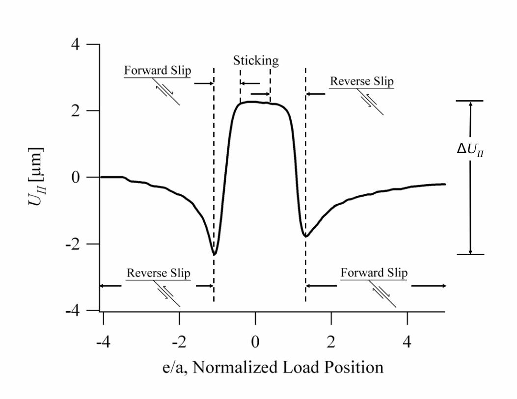
ΔUII

ΔUI

Variation of Sliding and Opening Displacements as a Function of Crack Length

Crack Propagation( ) ( ) 21
21m
IIm
I UCUCdNda
Δ+Δ=
C1
C2
da/dN
m1
m2
ΔUI
ΔUII
ΔUI , ΔUII
Data for da/dN in slidingis not available: Normalization by C1

10-72
4
10-62
4
10-52
4
10-4
(da/
dN)/C
1 [m
m/c
ycle
]
1210864Crack Length [mm]
C2/C1=m1=m2=2
0.001
0.01
0.1
2200 MPa 2000 MPa
Wear
Fatigue

Talk Outline (Konusma Taslağı)
•Fatigue/Deformation Preliminaries (Yorulma)
•Wheels- Thermo-mechanical Fatigue
(Tekerlekler,Termo-mekanik Yorulma)
•Rails- Ratcheting and Fatigue/Wear
(Raylar- Gerinme ve Aşınma)
•Materials Design- Diamond Crossing
•(Yeni Mazemelerin Atomik Boyutta Tasarımı-Makas Elması)
•Bearings- Cone Bore Growth
(Rulmanlı Yataklar)
•Conclusions (Sonuçlar)

Grinding Operations after Weld Metal deposition

FeMnN-Theory vs. Experiment - [111] Orientation
2000
1500
1000
500
0
True
Stre
ss (M
Pa)
0.200.150.100.050.00True Inelastic Strain
Hadfield Steel [111] Orientationunder Compression, T=293 K
Experiment Simulation
HNHS (1.06 wt.% N)
HSw/oN (0 wt.% N)

Pressure Vessel
Compressor
Vacuum Pump
Kanthal FurnaceGraphite FurnacePressure Vessel
Compressor
Vacuum Pump
Kanthal FurnaceGraphite FurnacePressure Vessel
Compressor
Vacuum Pump
Kanthal FurnaceGraphite Furnace
ASEA HIP30,000 PSI(2,069 Bar)
HIP EquipmentTensile TestingEquipment

Mechanical Testing
1. Strength increases with increased HIP treatment temperature
2. Some ductility can be regained by a subsequent 980C-30min treatment
3. Vickers hardness reflects strength trends4. Introducing nitrogen by welding can
increase strength
340
320
300
280
260
240
220
200
Vic
kers
Har
dnes
s (H
v)
110010501000950900
HIP Temperature (°C)
Virgin frog = 230 Hv
Average of nine measurementsper sample

Multilevel Microstructureas envisioned by Reamur in 1722
Hierarchical Materials-Mechanics Design
Structural Design( )αn( )αs
( )0αs
( )0αn
*RF
F p( )0αs
( )0αn
Quantum Mechanics (Design)
0.1nm
Micro-Mechanics (Design) Structural Mechanics (Design)
0.1mm 0.1m
QuickTime™ and aTIFF (LZW) decompressor
are needed to see this picture.
Nano- Mechanics (Design)
5 nm
Physics - Materials Science - Mechanical Sciences and Eng. (Mech./Aero/Civil)

Addition of nitrogen to Fe-based materials
J. Reed, J.Metals, 1989. Rawers and Slavens (1995)
Max at 1%N

Background- Dislocations are line defects in materials
Callister, Material Science and Engineering: An Introduction

Extended edge dislocationY
(111)
b
d
1b
2b X, 1 10⎡ ⎤⎣ ⎦
Z, 112⎡ ⎤⎣ ⎦b = b1 + b2
12
110⎡⎣ ⎤⎦ =16
211⎡⎣ ⎤⎦ +16
121⎡⎣ ⎤⎦
Z direction is equivalent to <112> direction for GSFE
X direction equivalent to <110> direction for GSFE

GSFE curve along <112>
Z, 112⎡ ⎤⎣ ⎦
uγSFγ
maxγu
sb
m
b
c
u
s
m
b
b
a
FCC lattice
<112>
HCP
FCC
X, 110⎡ ⎤⎣ ⎦
060
030
1 2116
⎡ ⎤⎣ ⎦
1 1216
⎡ ⎤⎣ ⎦
1 1102
⎡ ⎤⎣ ⎦
Z, 1 12⎡ ⎤⎣ ⎦
γ -curve along <112> direction
600 symmetry of γ surface
S. Kibey, J.B. Liu, M.J. Curtis, D.D. Johnson, H. Sehitoglu,"Stacking Fault Energy and Stacking Fault Widths in High
Nitrogen Steels," Acta Mater. 54, 2991-3001 (2006).

Fourier fit for GSFE Fe-4 at.%N
ux
12
<110>
zu1 <112>6
ux
12
<110>
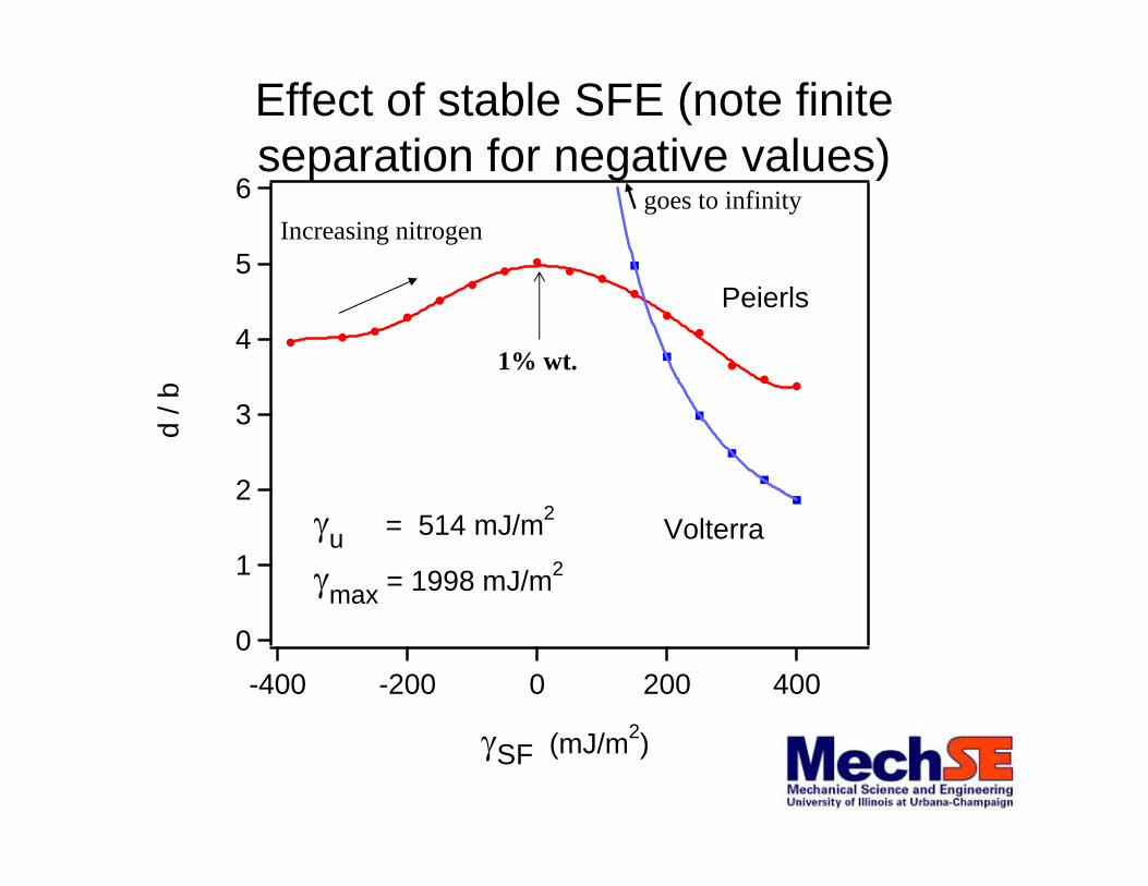
Effect of stable SFE (note finite separation for negative values)
6
5
4
3
2
1
0
d /
b
4002000-200-400
γSF (mJ/m2)
γu = 514 mJ/m2
γmax = 1998 mJ/m2
Volterra
Peierls
goes to infinityIncreasing nitrogen
1% wt.

Talk Outline (Konuşma Taslağı)
•Fatigue/Deformation Preliminaries (Yorulma)
•Wheels- Thermo-mechanical Fatigue
(Tekerlekler,Termo-mekanik Yorulma)
•Rails- Ratcheting and Fatigue/Wear
(Raylar- Gerinme ve Aşınma)
•Materials Design- Diamond Crossing
•(Yeni Mazemelerin Atomik Boyutta Tasarımı-Makas Elması)
•Bearings- Cone Bore Growth
(Rulmanlı Yataklar)
•Conclusions (Sonuçlar)

Neu, R. and H. Sehitoglu, "Determination of Cone Bore Growth Due to Microstructural Changes," ASME Journal of Tribology, 112, 433-441, 1990.
Neu, R. and H. Sehitoglu, "Transformation of Retained Austenite in
Carburized 4320 Steel,” Metallurgical Transactions, 22A, 1491-1500, 1990.

Neu, R. and H. Sehitoglu, "Low-Temperature Creep of a Carburized Steel,”Metallurgical Transactions, 23A, 2619-2624, 1992.
Neu, R. and H. Sehitoglu, "Thermal-Induced Transformations of Retained Austenite in the Simulated Case of a Carburized Steel," ASME Journal of Engineering Materials and


Neu, R. and H. Sehitoglu, "Simulation of Cone Bore Growth in Bearings with aThree-Ring Model," ASME Journal of Applied Mechanics, 61:3,589-595, 1994.


Talk Outline (Konuşma Taslağı)
•Fatigue/Deformation Preliminaries (Yorulma)
•Wheels- Thermo-mechanical Fatigue
(Tekerlekler,Termo-mekanik Yorulma)
•Rails- Ratcheting and Fatigue/Wear
(Raylar- Gerinme ve Aşınma)
•Materials Design- Diamond Crossing
•(Yeni Mazemelerin Atomik Boyutta Tasarımı-Makas Elması)
•Bearings- Cone Bore Growth
(Rulmanlı Yataklar)
•Conclusions (Sonuçlar)

Conclusions (Sonuçlar)
(1) ‘Mechanics of Materials’ plays a crucial role in understanding the integrity of the rails, wheels,crossings,bearings and other components. (Maddeler mekaniğiray, tekerlek,makas, ve yatay rulmanların güvenirliğinianlamak açısından önemli bir rol oynamaktadır.)
(2) New tools are available for experiments and modeling in the ‘mechanics and materials’ fields.(Deneylerve model yapmak için mühendislikte yeni gelişmelerortaya çıkmaktadır.)