Embed Size (px)
Citation preview

HP Archive
This vintage Hewlett Packard document was preserved and distributed by
www. hparchive.com Please visit us on the web !
On-line curator: Thomas Chrapkiewicz

~OloN
ll.:I:
· ,OPERATING AND SERVICE MANUAL
SINE IS·QUAREOSCILLATOR
209A
HEWLETT. PACKARD
www.HPARCHIVE.com
:I:~
NoIQ»

HEWLETT" PACKARD
CE RTI FI CATION
The Hewlett-Packard Company certifies that this instrument wasthoroughly tested and inspected and found to meet its publishedspecifications when it was shipped from the factory. The HewlettPackard Company further certifies that its calibration measurements are traceable to the U.S. National Bureau of Standards tothe extent allowed by the Bureau's calibration facility.
WARRANTY AND ASSISTANCE
All Hewlett-Packard products are warranted against defects inmaterials and workmanship. This warranty applies for one yearfrom the date of delivery, or, in the case of certain major components listed in the operating manual, for the specified period. Wewill repair or replace products which prove to be defective duringthe warranty period provided they are returned to HewlettPackard. No other warranty is expressed or implied. We are notliable for consequential damages.
Service contracts or customer assistance agreements are availablefor Hewlett-Packard products that require maintenance and repair on-site.
For any assistance, contact your nearest Hewlett-Packard Sales andService Office. Addresses are provided at the back of this manual.
www.HPARCHIVE.com

OPERATING AND SERVICE MANUAL
-hp- Part No. 00209-90002
MODEL
SINE/SQUARE
209A
OSCILLATOR
Serials Prefixed: 818-
Copyright Hewlett-Packard Company 1968P.O. Box 301, Loveland, Colorado, 80537 U.S.A.
www.HPARCHIVE.com
Printed: MAY 1970

Table of Contents Model209A
TABLE OF CONTENTS
APPENDICES
A. CODE LIST OF MANUFACTURERSB. SALES AND SERVICE OFFICESC. MANUAL BACKDATING CHANGES
Section PageVI REPLACEABLE PARTS 6-1
6-1. Introduction 6-16-4. Ordering Information 6-16-6. Non-Listed Parts 6-1
Section PageVII CIRCUIT DIAGRAMS 7-1
7-1. Introduction 7-17-3. Schematic Diagrams 7-17-5. Component Location Diagrams 7-1
Page
5-23.5-26.5-28.5-29.5-30.
SectionV MAINTENANCE (Cont'd)
5-8. Distortion Check 5-35-9. Output Voltage and Impedance
Check (Sine Wave) 5-45-10. Output Control Check
(Sine Wave) 5-45-11. Balance Check (Sine Wave) 5-45-12. Output Voltage Check
(Square Wave) 5-45-13. Rise Time Check
(Square Wave) 5-55-14. Symmetry Check
(Square Wave) 5-55-15. Sync Output Check 5-55-16. Sync Input Check 5-55-1 7. Cover Removal . . . . . . . . . . . . . . . . . 5-65-22. Adjustment and Calibration
Procedure 5-6Introduction 5-6Power Supply 5-6Bias Adjustment 5-6AGC Adjustment 5-6AGC and Frequency
Adjustment 5-65-31. High Frequency Adjustment 5-75-32. Distortion Adjustment 5-75-33. Symmetry Adjustment 5-75-34. Factory Selected Components 5-75-36. Troubleshooting Procedures 5-85-37. Front Panel Procedure 5-85-40. Detailed Circuit
Troubleshooting 5-8
Section PageV MAINTENANCE 5-1
5-1. Introduction 5-15-4. Performance Checks 5-15-6. Dial Accuracy Check 5-15-7. Flatness Check 5-1
Section PageI GENERAL INFORMATION 1-1
1-1. Introduction 1-11-3. Specifications 1-11-5. Description 1-11-10. Instrument/Manual Identification .. 1-1
Section PageII INSTALLATION 2-1
2-1. Introduction 2-12-3. Initial Inspection 2-12-5. Power Requirements 2-12-7. Grounding Requirements 2-12-10. Installation 2-12-12. Bench Mounting 2-12-14. Rack Mounting 2-12-16. Combination Mounting 2-12-18. Repackaging for Shipment 2-1
Section PageIII OPERATING INSTRUCTIONS 3-1
3-1. Introduction 3-13-3. Turn On Procedure 3-13-5. Operating Considerations 3-13-6. Floating Output 3-13-8. Balance 3-13-10. Synchronization 3-13-13.. Low Distortion 3-1
Section PageIV THEORY OF OPERATION 4-1
4-1. Introduction 4-14-4. Block Diagram Description , 4-14-5. Bridge and Amplifier 4-14-9. Peak Comparator and AGC _ 4-14-13. Buffer Amplifier 4-24-15. Sine-Square Converter 4-24-17. Detailed Circuit Description 4-24-25. Power Supply 4-2
iii
www.HPARCHIVE.com

Model209A
LIST OF TABLES
Table of Contents
Number Page1-1. Specifications 1-05-1. Required Test Equipment 5-05-2. Dial Accuracy Check 5-15-3. Flatness Check 5-2
Number Page5-4. Distortion Check 5-35-5. Factory Selected Components 5-75-6. Front Panel Symptoms 5-86-1. Replaceable Parts 6-2
LIST OF ILLUSTRATIONS
Number Page1-1. Model 209A Sine/Square Oscillator 1-12-1. Dimensions 2-23-1. Description of Controls and Connectors 3-04-1. Model209A Block Diagram 4-04-2. RC Frequency Network Characteristics 4-15-1. Dial Accuracy Check 5-1
5-2. Flatness Check 5-25-3. 2 MHz Distortion Check 5-35-4. Balance Check 5-45-5. Sync Input Check 5-56-1. Front Panel Exploded View 6-47-1. Oscillator Schematic (AI) 7-3/7-47-2. Power Supply Schematic (A2) 7-5/7-6
iv
www.HPARCHIVE.com
Section I
-RANGES-
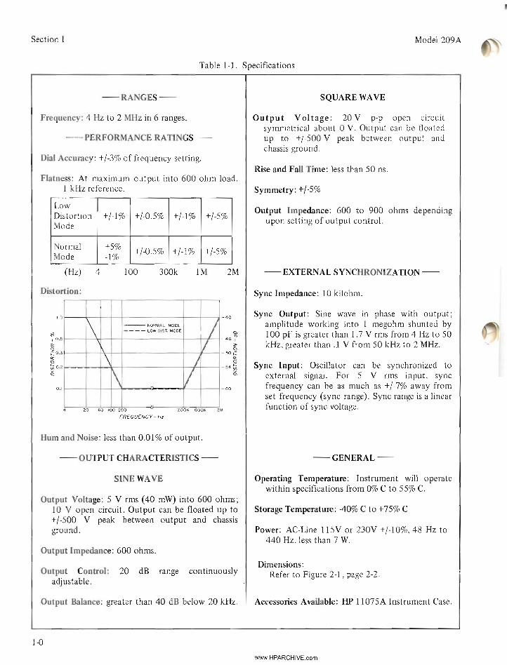
Table 1-1. Specifications
SQUARE WAVE
Model209A
Frequency: 4 Hz to 2 MHz in 6 ranges.
- PERFORMANCE RATINGS-
Dial Accuracy: +/-3% of frequency setting.
Flatness: At maximum output into 600 ohm load.1 kHz reference.
LowDistortion +/-1% +/-0.5% +/-1% +/-5%Mode
Output Voltage: 20 V pop open circuitsymmetrical about 0 V. Output can be floatedup to +/-500 V peak between output andchassis ground.
Rise and Fall Time: less than 50 ns.
Symmetry: +/-5%
Output Impedance: 600 to 900 ohms dependingupon setting of output control.
NormalMode
+5%-1%
+/-0.5% +/-1% +/-5%
(Hz) 4
Distortion:
100 300k 1M 2M - EXTERNAL SYNCHRONIZATION-
Sync Impedance: 10 kilohm.
1.0 -40
\ --NORMAL MODE /*- - - - LOW D1ST. MODE
I 0.5
/46.,
Ci: 0.3
\50
Q: Ict:; 0.2
V54
Ci \0.1 60
20 60 100 200
FREQUENCY-Hz20DK 60CK 2M
Sync Output: Sine wave in phase with output;amplitude working into 1 megohm shunted by100 pF is greater than 1.7 V rms from 4 Hz to 50kHz, greater than .1 V from 50 kHz to 2 MHz.
Sync Input: Oscillator can be synchronized toexternal signal. For 5 V rms input, syncfrequency can be as much as +/-7% away fromset frequency (sync range). Sync range is a linearfunction of sync voltage.
--
Hum and Noise: less than 0.01% of output.
- OUTPUT CHARACTERISTICS-
SINE WAVE
Output Voltage: 5 V rms (40 mW) into 600 ohms;10 V open circuit. Output can be floated up to+/-500 V peak between output and chassisground.
Output Impedance: 600 ohms.
Output Control: 20 dB range continuouslyadjustable.
Output Balance: greater than 40 dB below 20 kHz.
1-0
-GENERAL-
Operating Temperature: Instrument will operatewithin specifications from 0% C to 55% C.
Storage Temperature: 40% C to +75% C
Power: AC-Line 115V or 230V +/-10%,48 Hz to440 Hz. less than 7 W.
Dimensions:Refer to Figure 2-1, page 2-2.
Accessories Available: HP 1l075A Instrument Case.
www.HPARCHIVE.com

Model209A
SECTION I
GENERAL INFORMATION
Section I
1-1. INTRODUCTION.
1-2. This section contains general information aboutthe -hp- Model 209A Sine/ Square Oscillator.Throughout this manual the instrument will bereferred to as the Mode1209A.
1-3. SPECIFICATIONS.
1-4. Table 1-1 lists the specifications for the Model209A.
1·5. DESCRIPTION.
1-6. The Model 209A is a versatile signal source withindependent sine wave and square wave outputs atfrequencies from 4 Hz to 2 MHz. The square waveamplitude is variable to a maximum of 20 voltspeak-to-peak into open circuit. The sine waveamplitude is variable to a maximum of 10 volts rmsinto open circuit from a constant 600 ohm source.When working into a 600 ohm load, the maximumoutput level is 5 volts rms.
1-7. Balanced output can be obtained bydisconnecting the grounding strap at the rear of theinstrument. This isolates the chassis from the cabinetand line ground. The sine wave output will balance to
greater than 40 dB, at frequencies below 20 kHz,with the chassis isolated.
1-8. The Model 209A can be synchronized with anexternal source. With a 5 volt rms sync input, theexternal source may vary as much as +/-7% infrequency and the Model 209A will remainsynchronized.1-9. A sync output of 1.7 volts rms is also availableat the same front panel terminal used to accept anexternal sync source.
1-10. INSTRUMENT/MANUAL IDENTIFICATION.1-11. Hewlett-Packard uses a two-section serialnumber. The first section (prefix) identities a series ofinstruments. The last section (suffix) identifies aparticular instrument within the series. If a letter isincluded with the serial number, it identifies thecountry in which the instrument was manufactured.If the serial prefix of your instrument differs fromthe one on the title page of this manual, a changesheet will be supplied to make this manualcompatable with newer instruments or the backdatinginformation in Appendix C will adapt this manual toearlier instruments. All correspondence withHewlett-Packard should include the complete serialnumber.
Figure 1-1. Model 209A Sine/Square Oscillator
1-1
www.HPARCHIVE.com

Model209A
SECTION II
INSTALLATION
Section II
2-1. INTRODUCTION.
2-2. This section contains information andinstructions necessary for installing and shipping theModel 209A Sine / Square Oscillator. Included areinitial inspection procedures, power and groundingrequirements, installation information, andinstructions for repackaging for shipment.
2-3. INITIAL INSPECTION.
2-4. This instrument was carefully inspected bothmechanically and electrically before shipment. Itshould be physically free of mars or scratches and inperfect electrical order upon receipt. To confum this,the instrument should be inspected for physicaldamage that occurred in transit. If the instrument wasdamaged in transit, me a claim with the carrier. Testthe electrical performance of the instrument usingPerformance Checks outlined in Section V. If there isdamage or deficiency, see the warranty on the insidefront cover of this manual.
2-5. POWER REQUIREMENTS.
2-6. The standard Model 209A will operate from anysource of 115 or 230 volts (+/-10%), at 48 to 440 Hz.With the instrument disconnected from the ac powersource, move the voltage selector switch (located onthe rear panel) so the designation appearing on theswitch matches the voltage of the power source to beused. Power dissipation is less than 7 watts.
2-7. GROUNDING REQUIREMENTS.
2-8. To protect operating personnel, the NationalElectrical Manufacturers Associatfon (NEMA)recommends that the instrument cabinet begrounded. The standard Model 209A is equipped witha three-conductor power cable which, when pluggedin to an appropriate receptacle, grounds theinstrument. The offset pin on the power cablethree-prong connector is the ground connection.
2-9. To preserve the protection feature whenoperating the instrument from a two-contact outlet,use a three-prong to two-prong adapter and connectthe green pigtail on the adapter to earth ground.
2·10. INSTALLATION.
2-11. The Model 209A is fully transistorized;therefore, no special cooling is required. However, theinstrument should not be operated where the ambienttemperature exceeds 550 C (131 0 F).
2-12. BENCH MOUNTING.
2-13. The Model 209A is shipped with plastic feetand tilt stand in place, ready for use as a benchinstrument.
2-14. RACK MOUNTING.
2-15. The Model 209A may be rack mounted byusing an adapter frame (-hp- Part No. 5060-0797).The adapter frame is a rack frame that accepts anycombination of -hp- submodular units. It can be rackmounted only. For additional information, addressinquiries to your -hp- Sales and Service office. (SeeAppendix B for office locations.)
2-16. COMBINATION MOUNTING.
2-17. The Model 209A may be mounted incombination with other submodular units by using aCombining Case (-hp- Model 1051A or 1052A). TheCombining Case is a full-module unit which acceptsvarious combinations of submodular units. Being afull-module unit, it can be bench or rack mountedand is analogous to any full-module unit.
2-18. REPACKAGING FOR SHIPMENT.
2-19. The following paragraphs contain a generalguide for repackaging of the instrument for shipment.Refer to Paragraph 2-20 if the original container is tobe used; 2-21 if it is not. If you have any questions,contact your local -hp- Sales and Service Office. (SeeAppendix B for office locations.)
2-1
www.HPARCHIVE.com

Section II Model209A
-----NOTE----If the instrument is to be shippedto Hewlett-Packard for service orrepair, attach a tag to theinstrument identifying the ownerand indicating the service or repairto be accomplished; include themodel number and full serialnumber of the instrument. In anycorrespondence, identify theinstrument by model number andfull serial number.
2-20. If the original container is to be used, proceedas follows:
a. Place the instrument in the originalcontainer if available. If the originalcontainer is not available, one can bepurchased from your nearest -hp- Sales andService Office.
b. Ensure that the container is well sealed withstrong tape or metal bands.
2-21. If the original container is not to be used,proceed as follows:
a. Wrap the instrument in heavy paper orplastic before placing it in an innercontainer.
b. Place packing material around all sides of theinstrument and protect the panel face withcardboard strips.
c. Place the instrument and inner container in aheavy carton or wooden box and seal withstrong tape or metal bands.
d. Mark the shipping container with"DELICATE INSTRUMENT", "FRAGILE"etc.
Dimensions:
209ATOP 8
(203,21
"-----------,,L~ 5i ('30'21~
~t
(10.3)
DIMENSIONS IN INCHES AND (MILLIMETERS)
[ TSIDE 6f2
~(154,e)
~e "~
Figure 2-1. Dimensions
2-2
www.HPARCHIVE.com

Section III Model209A
2
SYNC
""""I "'AX
6000
3
9
10,",-LINE
SELECTOR
o ~IIS/230V± 10%
48-440"" TVA MAX
CHANGEFREQ.
SLOWLYI
,OWNORM OISl.
""
~~~~ ~ ~
CD RANGE Switch: Selects frequency range orOFF position.
eD Frequency Dial: Selects frequency withindesired range. Dial setting multiplied byRANGE switch position indicates outputfrequency.
o Frequency Vernier: Provides fine tuning offrequency dial.
o Square Wave Amplitude Control: VariesSquare Wave output level to 20 voltspeak-to-peak, open circuit.
eD Sine Wave Amplitude Control: Varies SineWave output level over a 20 dB range to 10volts rms, open circuit (5 volts rms into 600ohms).
CD Sine Wave Output Terminal: 600 ohm sinewave output at a frequency and amplitudedetermined by control settings.
CD Square Wave Output Terminal: 600 ohmsquare wave output at a frequency andamplitude determined by control settings.
CD SYNC Terminal: (1) Input terminal for anexternal sync signal. (2) Output terminal for1.7 volt rms sine wave sync signal.
CD Ground Strap: Connects the floating circuitground to power ground.
® Voltage Selector Switch: Selects line voltageof 115 volts or 230 volts AC.
® AC Power Receptacle: Mates with powercord supplied with this instrument for linevoltage connection.
@ NORM/LOW DIST. Switch: Selects normalor low distortion below 100 Hz.
Figure 3-1. Description of Controls and Connectors
3-0www.HPARCHIVE.com

Mode1209A
3·1. INTRODUCTION.
SECTION III
OPERATING INSTRUCTIONS
3-8. BALANCE.
Section III
3-2. This section contains information as an aid tooperating the Model 209A. Included are control andconnector descriptions (Figure 3-1), and some specialoperating considerations.
3-3. TURN ON PROCEDURE.
34. To turn on the Model 209A, proceed as follows:
a. Set the two-position voltage selector switchon the rear panel to the value of availableline voltage.
b. Connect the AC power cord to line voltage.
c. Switch the RANGE switch from OFF to thedesired frequency range.
d. Select the desired frequency and voltageoutput with the frequency dial andamplitude controls respectively.
3-5. OPERATING CONSIDERATIONS.
3-6. FLOATING OUTPUT.
WHEN THE GROUND STRAP ONTHE REAR PANEL ISCONNECTED, INPUT GROUNDIS AT EARTH GROUNDPOTENTIAL.
3-7. When the ground strap on the rear of the Model209A is disconnected, the chassis is isolated frompower ground. The outputs may then be connectedto any point with a dc potential of not more than+/-500 volts. If a dc voltage up to +/-500 volts isconnected between the ground connectors on the rearpanels, the oscillator output is dc offset by thatamount.
3-9. With the chassis isolated from the cabinet, thesine wave output will be balanced to greater than 40dB at frequencies below 20 kHz. If the square waveoutput is being used simultaneously with the blackterminal connected to ground, the sine wave outputwill no longer be balanced.
3-10. SYNCHRONIZATION.
3-11. The Model 209A is equipped with a SYNCterminal that provides a sync output signal or acceptsa synchronizing input signal from an external source.The sync output signal is a 1.7 volt rms sine wave inphase with the oscillator output. The external syncsignal can be any periodic waveform of sufficientamplitude to maintain sync. For an external syncsignal with an amplitude of 5 volts rms, the oscillatorwill remain synchronized at frequencies of +/-7% ofthe set frequency.
3-12. The Model 209A can be synchronized to anysignificant harmonic of an external signal. However, ifa harmonic or non-sinusoidal waveform is used tosynchronize the Model 209A, some portion of theexternal sync signal will be on the output. This smallsignal will appear as distortion. The amount of thisapparent distortion will be directly proportional tothe amplitude of the sync signal. For a non-sinusoidalsync input of 2 volts peak-to-peak, the distortion willbe down about 45 dB for frequencies which arenormally down -60 dB.
3-13. LOW DISTORTION.
3-14. At frequencies below 100 Hz, distortion can bereduced by switching the NORM/LOW DIST switchon the rear panel to LOW DIST. In the LOW DISTmode the Model 209A will have a longer settling timewhen changing frequencies. To avoid this, set thedesired frequency before switching to LOW DIST.
3-1www.HPARCHIVE.com

+>- 6
Ul
('l)
(") .... o' :::3 <:
BR
IDG
E
CIA
~ %
~~
PE
AK
CO
MP
AR
AT
OR
AM
PL
IFIE
R")
•~
•+
R2
8
R2
4
AG
C
RI6
R8
//
//
( I I I I I ~ /I
FR
EQ
UE
NC
Yr<
ID
IAL
UI I I I
:?i<C
IB1
/v
i J:: ~ ;u o I <: m "o 3
20
9A
-B-1
61
4A
7.2
VR
EF
SY
NC
Figu
re4-
1.M
odel
209A
Blo
ckD
iagr
am
a:: o 0~ tv o \0 ;I>
.'~
8

Model209A Section IV
SECTION IV
THEORY OF OPERATION
4-1. INTRODUCTION.
4-2. This section contains a description of the basicprinciples of circuit operation for the Model 209A.The information is presented as a discussion of eachblock indicated on the Block Diagram, Figure 4-1,and detailed circuit descriptions which refer to Figure7-1 and 7-2.
4-3. The Model 209A is basically a Wien bridgeoscillator. The output from the oscillator circuit isapplied to a buffer amplifier and to a sine wave tosquare wave converter. These two circuits provideindependent sine wave and square wave outputs,respectively.
4-4. BLOCK DIAGRAM DESCRIPTION.
furnished through the frequency determiningnetwork of CIA, R8, CIB, and R16. At thefrequency that the phase of the positive feedback is00
, Xc = R and the maximum ratio of outputvoltage is supplied to the amplifier (see Figure 4-2).The characteristics of the Wien bridge are such thatthe output voltage to the + input of the amplifier atF 0 is one third the amplitude of the positive feedbackvoltage. Therefore, to maintain unity gain andoscillation, the negative feedback network (R28, R24and AGC) was designed with a divider ratio of two toone, to give the amplifier a gain of three.
4-8. The amplifier itself is a solid-state, high gainamplifier with the output in phase with the input sothat feedback will produce oscillations.
4-9. PEAK COMPARATOR AND AGC.
-RATIO
FREQUENCY
4-5. BRIDGE AND AMPLIFIER.4-10. The voltage output from the Wien bridge to theinput of the amplifier is not always one third of thepositive feedback voltage at all operating frequencies,nor is the amplifier gain constant for all operatingfrequencies. One technique used for maintainingunity gain in the oscillator circuit at all operatingfrequencies is to have a dynamic resistance, variablewith changes in gain, in the negative feedbacknetwork. In the Model 209A this is accomplishedwith the combination of the peak comparator andAGC circuits.
4-12. When the oscillator is first turned on, the AGCgives the amplifier a gain of much greater than three.Noise in the amplifier is amplified greatly, and thefrequency selective network in the Wien bridge selectsthe noise at the tuned frequency. The selected noisebecomes positive feedback to the amplifier, and theamplifier starts oscillating at the tuned frequency. Asthe output amplitude approaches 7.2 volts peak, the
4-11. The peak comparator compares the negativepeak of the oscillator amplifier output to a 7.2 voltreference. If the output varies above or below thereference voltage, a difference voltage will be suppliedto the AGC circuit. The "dynamic resistance" of theAGe circuit is a field-effect transistor with the gatecontrolled by the difference signal from the peakcomparator. The oscillator amplifier output is held to7.2 volts peak amplitude.
LEAD
LAG--/
--//
.".......- -......... //-/
/ //~
/ / -- ""--~//
/
~I -
----- PHASE
Epf s POSITIVE FEEDBACK VOLTAGE TO AMPLIFIER
Eo " OSCILLATOR CIRCUIT OUTPUT VOLTAGE
F0 " FREQUENCY WHERE Xc 11 R
0.4
o.
Figure 4-2. RC Frequency Network Characteristics
4-6. An overall loop gain of at least unity is arequirement for any amplifier to oscillate. The Model209A satisfies this requirement with a combination ofpositive and negative feedback through the bridge.
4-7. The oscillator bridge is divided into twonetworks, the frequency selective network and thenegative feedback network. Positive feedback is
4-1www.HPARCHIVE.com
Section IV
AGC reduces the gain of the amplifier to three; andstable oscillation is achieved.
4-13. BUFFER AMPLIFIER.
4-14. The 5 volt rms sine wave output from theoscillator circuit is coupled to the buffer amplifier.The amplifier has a high open loop gain that iscontrolled by the negative feedback to provide a gainof 2. This enables the circuit to have very lowdistortion characteristics. The buffer amplifier uses acomplementary symmetry transistor pair to furnish a10 volt rms output.
4-15. SINE-SQUARE CONVERTER.
4-16. The 5 volt rms sine wave output from theoscillator circuit is also applied to the sine-squareconverter. The sine wave is coupled to a tunnel diodewhich produces a small square wave output with fastrise and fall times. This small square wave signal isthen shaped and amplified. It appears at the output asa 20 volt peak-to-peak square wave.
4-17. DETAILED CIRCUIT DESCRIPTION.
4-18. For the following paragraphs, refer to theOscillator Schematic Diagram, Figure 7-1 .
4-19. Transistors AIQI through AIQ7 make up thebasic oscillator amplifier. Al QI is an N-channel FET.Al CRI sets up proper de bias for Al Q2. DiodesAICR6, AICR7, AICR8 set up proper bias forAl Q4. Capacitor Al C9 is chosen to provide a stableroll off at high frequencies. Al Q7 is a current sourcefor AIQ3 and AIQ4. AICR4 and AICR5 provideproper biasing for complementary output transistorsAl Q5 and Al Q6.
4-20. The positive feedback arm of the Wien bridgeconsists of tuning capacitors AICIA and AIClB, andrange switching resistors Al RI through Al RI7.
4-21. The negative feedback arm of the Wien bridgedepends upon the ratio of the impedance of Al R28to the total impedance of Al R23, Al R24, Al R25,and Al Q8. Al R25 reduces the effect of the FETAl Q8 to increase stability. Al Q8 proVides AGC forthis amplifier by varying impedance to obtain theproper negative feedback.
4-2
ModeI209A
4-22. The conduction of FET Al Q8 is controlled bythe peak detector circuit using AIQ9. AIQ9 conductsduring the most negative portion of each negative halfcycle, developing a negative charge in Al C15 and itsparallel capacitors. As the amplifier output amplitudeincreases, Al Q9 conducts more and Al C15 becomesmore negatively charged. This makes the FET inputvoltage more negative, increasing its impedance andincreasing the negative feedback to reduce the outputamplitude of the amplifier.
4-23. Transistors AIQ13 through AIQI8 comprise abuffer amplifier with a gain of two. AIQ13 andAIQI4 form a differential amplifier. Diodes AICRI8and Al CRI9 furnish proper biasing forcomplementary output transistors Al QI7 andAl QI8. When the output attenuator Al R79 is fullyclockwise, the output amplitude is greater than 10volts rms. When the attenuator is fullycounter-clockwise, the output is attenuated bygreater than 20 dB.
4-24. The Sine-Square Converter circuit includesAl QlO through Al QI2. This converter circuitoperates as a saturating amplifier. Tunnel diodeAl CRI2 squares the sine wave input, and theSymmetry Adjust Al R45 determine the level whereconduction starts. This provides for adjustment of thesymmetry of the square wave. Zener diode Al CRI5sets the voltage level of the negative portion of thesquare wave. Al QI2 furnishes the positive portion ofthe square wave output, and Al QII furnishes thenegative output.
4-25. POWER SUPPLY.
4-26. The following paragraphs refer to the PowerSupply Schematic, Figure 7-2.
4-27. This power supply is a series regulated powersupply furnishing +21 volts and -21 volts. Zener diodeA2CR6 serves as a reference for the positive powersupply, which in turn serves as the reference for thenegative supply. The positive supply is described here,and the negative supply operates similarly.
4-28. Transistor A2QI regulates the output voltageand is controlled by A2Q3. A2Q2 is a current sourcefor A2Q3. Zener diode A2CR5 furnishes bias forA2Q2, while A2R2 injects negative ripple feedback.A2CR6 sets the emitter voltage of A2Q3, setting up areference for the supply output. A2Q4 current limitsthe output to prevent damage to the supply.
www.HPARCHIVE.com
I
I
I
I
I
I
I
I
I
I
I
I
I
I
I
I
I
I
I
I

Section V
Table 5-1. Required Test Equipment
Model209A
INSTRUMENT REQUIREDRECOMMENDED MODEL
SPECIFICAnONS
Frequency Accuracy: +/-1 count -hp- Model 5233LCounter Range: 4 Hz to 2 MHz
AC Voltmeter Range: 10 Hz to 2 MHz -hp- Model 400ESensitivity: 1 mV to 10 VAccuracy: +/-2%
DC Null Sensitivity: 10 uV to 20 V -hp- Model 419AVoltmeter Accuracy: +/-2% of full scale
Distortion Range: 5 Hz to 600 kHz -hp- Model 334AAnalyzer Fundamental Rejection:
greater than 60 dB
Test Range: 10 Hz to 2 MHz -hp- Model 651 BOscillator Output: 5 V rms open circuit
Oscilloscope Frequency Range: 4 Hz to -hp- Model 140A20 MHz (plug-ins) 1402A
Sweep Speed: 50 nsec/cm l420A
Thermal Accuracy: +/-0.2% -hp- Model H08-11 049AConverter Frequency Range: 5 Hz to 2 MHz
Voltage Input: 5 V rmsInput Impedance: 600 ohms
Bucking See Figure 5-2 for diagramSupply a. R: fxd 6500 ohms -hp- Part No. 0811-0392
b. R: var 500 ohms -hp- Part No. 2100-0324c. R: var 50 ohms -hp- Part No. 2100-1481d. Battery: 1.34 V Mallory RM-42R
2 MHz Notch See Figure 5-3 for diagramFilter a. C: fxd 30 pF -hp- Part No. 0160-0181
b. C: fxd 400 pF (2) -hp- Part No. 0150-0071c. L: fxd 30 uH -hp- Part No. 9100-1624d. R: fxd 1 kilohm -hp- Part No. 0686-1025e. R: fxd 82 kilohms -hp- Part No. 0686-8235f. R: var 10 kilohms -hp- Part No. 2100-1776
Balance See Figure 5-4 for diagramNetwork a. R: fxd 300 ohms +/-0.1% -hp- Part No. 0811-0029
b. R: fxd 150 ohms +/-1% -hp- Part No. 0757-0715
Terminating R: fxd 600 ohms +/-1% -hp- Part No. 0757-1100Resistance
Capacitor C: fxd 100 pF +/-10% -hp- Part No. 0150-0073
5-0www.HPARCHIVE.com

Model209A
SECTION V
MAINTENANCE
5-1. INTRODUCTION. Table 5-2. Dial Accuracy Check
Section V
5-2. This section contains information necessary forthe maintenance of the Model 209A Sine/Squareoscilla t or. Included are performance checks,adjustment and calibration procedures, andtroubleshooting procedures.
5-3. The test equipment needed to properly maintainand service the Model 209A is listed in Table 5-1. Ifthe recommended model is not available, otherequipment may be substituted provided it meets therequired specifications.
5·4. PERFORMANCE CHECKS.
5-5. The performance checks presented in thissection are designed to compare the Model 209A withits published specifications. These checks can be usedfor incoming inspection, periodic maintenancechecks, and to verify performance after adjustment orrepair. A performance check test card appears at theend of this section which can be used to record theperformance specifications.
5-6. DIAL ACCURACY CHECK.
a. Connect the Model 209A and the FrequencyCounter as shown in Figure 5-1. Set thecounter to measure frequency and check theModel 209A at the frequencies listed inTable 5-2 for the tolerances indicated.
b. If the above dial accuracy checks fail tomeet the required specifications, refer to theAdjustment and Calibration Procedure inthis section.
RANGE FREQUENCY COUNTERSWITCH DIAL INDICATION
X2 2 4 Hz +/-0.1 HzX2 5 10 Hz +/-0.3 HzX2 20 40 Hz +/-1.2 HzX10 2 20 Hz +/-0.6 HzX10 5 50 Hz +/-1.5 HzXlO 20 200 Hz +/-6 HzXlOO 2 200 Hz +/-6 HzX100 5 500 Hz +/-15 HzXlOO 20 2 kHz +/-60 HzX1K 2 2 kHz +/-60 HzX1K 5 5 kHz +/-150 HzX1K 20 20 kHz +/-600 HzXlOK 2 20 kHz +/-600 HzX10K 5 50 kHz +/-1.5 kHzX10K 20 200 kHz +/-6 kHzXlOOK 2 200 kHz +/-6 kHzXlOOK 5 500 kHz +/-15 kHzX100K 20 2 MHz +/-60 kHz
5-7. FLATNESS CHECK.
a. Connect the equipment as shown in Figure5-2.
-----NOTE----The BUCKING SUPPLY should beconstructed from the componentslisted in Table 5-1. The 500 ohmcontrol should be used as a coarseadjust and the 50 ohm controlshould be used as a fine adjust
hp 209AOSCILLATOR
@ ELECTRONIC COUNTERhp5233L
II :o~ I I @@]b00@@.,.,'" o o\)
~ I209A-e-1661
Figure 5-1. Dial Accuracy Check
www.HPARCHIVE.com 5-1

PERFORMANCE CHECK TEST CARO (Cont'd)
DESCRIPTION CHECK
Distortion:
Range Dial NORM LOWDIST--X2 2.5 -40 dB -54 dBX2 10 -40 dB -54 dBXlO 2 -40 dB -54 dBXlO 10 -54 dBX100 2 -60 dBXI00 10 -60 dBXIK 2 -60 dBXIK 10 -60 dBX10K 2 -60 dBXI0K 10 -60 dBXIOOK 2 -60 dBXI00K 6 -50 dBXI00K 20 -40 dB
Output Voltage and Impedance(Sine Wave):
No load 10 Vrms600 ohm load 5 Vrms
Output Control (Sine Wave): <1 V rrns
Balance (Sine Wave): -40 dB
Output Voltage (Square Wave): 20 V pk-pk
Rise and Fall Time (Square Wave): 50 nsec
Symmetry (Square Wave): +/-0.5 cm
Sync Output: 1.7 V rms
Sync Input: < 18.6 kHz > 21.4 kHz
www.HPARCHIVE.com

DC NULLVOLTMETER
hp 419A
Section V
@D00'i>@@'i>'i>
I II II ,----------,---------
209A-B-I662
THERMALCONVERTER
hp H08-II049A
BUCKING SUPPLYr--------------,I II II 6500n II II ~on II II 1.34V I
I II I
'-------~~50Il I
II I~--------------~
Mode1209A
Figure 5-2. Flatness Check
b. Set the Model 209A RANGE switch toXlOO and the frequency dial to 10. Set theAMPLITUDE control to maximum output.
c. Adjust the BUCKING SUPPLY 50 ohm finecontrol for minimum resistance, and recordthe THERMAL CONVERTER output asindicated on the DC NULL VOLTMETER.
the DC NULL VOLTMETER indication bythe THERMAL CONVERTER outputvoltage recorded in step c of this paragraph.Multiply this value by 100 to get percent ofoutput change. Divide this percentage by theTHERMAL CONVERTER multiplier toobtain a percentage within the toleranceslisted in Table 5-3.
d. Adjust the BUCKING SUPPLY coarse andfine controls for a OV indication on the DCNULL VOLTMETER. Do not readjust theBUCKING SUPPLY controls for theremainder of this check.
e. Check the Model 209A flatness at thefrequencies listed in Table 5-3, recording theDC NULL VOLTMETER indication for eachfrequency.
Example:
FrequencyTHERMAL CONVERTER outputDC NULL VOLTMETER readingCalibration Report multiplierTable 5-3 tolerance
.025 mV x 100% = 0.29%5 mV x 1.7
100 kHz5mV
25 uV1.7
+/-0.5%
5-2
NOTEThe THERMAL CONVERTER isconsidered a square-law device.Therefore, theoretically, thepercent of change at the output ofthe THERMAL CONVERTERshould be 2 times the percent ofchange at the input. Actually thevalue is not quite 2. The number istypically 1.7. The multiplier (M)can be determined by measuringthe output (Ei) for a given input,doubling the input and againmeasuring the output (EF). Themultiplier is then determined bythe following formula:
M = EF/2Ei
f. Convert each reading on the DC NULLVOLTMETER to the percentages listed inTable 5-3 by the following procedure. Divide
Table 5-3. Flatness Check
Frequency Toleran~e
Dial RANGE NORM LOWSetting Setting mST.
2.5 X2 +5% -1% +/-1%10 X2 +5% -1% +/-1%2.5 X10 +5% -1% +/-1%
10 X10 +/-0.5%2.5 X100 +/-0.5%
10 X100 SET2.5 XlK +/-0.5%
10 X1K +/-0.5%2.5 XlOK +/-0.5%
10 XlOK +/-0.5%3 XlOOK +/-0.5%
10 X100K +/-1 %20 X100K +/-5%
www.HPARCHIVE.com

Mode1209A Section V
hp209A AC VOLTMETER
OSCILLATOR hp 400E
@ 2MHz NOTCH FILTER ~r--------------,I II 30PF I @
QOO I I
Ii @ ®I I@@@<il<il I 82KO I
I I
4:t> I 30~H IJI I
~ fJ: .oo~o" II II IKO II I
209A-B-I663L_____ 1~~n___J
a. Connect the Model 209A sine wave outputwith a 600 ohm load to the DistortionAnalyzer.
5-8. DISTORTION CHECK.Figure 5-3. 2 MHz Distortion Check
h. Repeat steps a through f of this paragraphfor all frequencies listed in Table 54.
i. Connect the equipment as shown in Figure5-3.
b. Set the Model 209A controls as follows:
Dial .10RANGE X100Amplitude Full CWNORM/LOW DIST NORM
c. Set the Distortion Analyzer controls asfollows:
Dial 10FREQUENCY RANGE X100METER RANGE 0 dBFUNCTION SET LEVELSENSITIVITY MINMODE MANUAL
d. Inc rease the Distortion AnalyzerSENSITIVITY to obtain a 0 dB indicationon the meter.
e. Switch the Distortion Analyzer FUNCTIONto DISTORTION, and adjust the DistortionAnalyzer dial and BALANCE controls for anull indication on the meter.
f. When an approximate null has been obtainedwith the Distortion Analyzer dial andBALANCE controls, switch the MODE toAUTOMATIC for minimum meterindication.
g. Meter indication should be greater than 60dB down from the 0 dB reference.
j. Set the Model 209A frequency dial to 20and the RANGE switch to X1K. Adjust thesine wave amplitude control for a 0 dBindication on the AC Voltmeter.
k. Switch to the X100K RANGE, and adjustthe frequency dial and notch filter controlfor a minimum indication on the ACVoltmeter.
1. The meter indication should be greater than40 dB down from the 0 dB reference.
Table 5-4. Distortion Check
Frequency Tolerance
Dial RANGE LOWSetting Setting NORM DIST.
2.5 X2 -40 dB -54 dB10 X2 -40 dB -54 dB2 X10 40 dB -54 dB
10 X10 -54 dB2 X100 -60 dB
10 X100 -60 dB2 X1K -60 dB
10 X1K -60 dB2 X10K -60 dB
10 X10K -60 dB2 X100K -60 dB6 X100K -50 dB
5·3www.HPARCHIVE.com

Section V
5-9. OUTPUT VOLTAGE AND IMPEDANCECHECK (SINEWAVE).
a. Connect the Model 209A sine wave outputwithout a 600 ohm load to the ACVoltmeter.
b. Set the AC Voltmeter to the 10V RANGE,and the Model 209A sine wave amplitude tomaximum at a frequency setting of 20 kHz.
c. The meter should indicate at least 10 V rms.
d. Reduce the 209A output to 10 V rrns.
e. Connect a 600 ohm load to the Model 209A.
f. The AC Voltmeter should indicate 5 voltsrms, verifying the output voltagespecification and an approximate outputimpedance of 600 ohms.
5-10. OUTPUT CONTROL CHECK (SINE WAVE).
a. Connect the Model 209A sine wave outputwithout a 600 ohm load to the ACVoltmeter.
b. Adjust the Model 209A sine wave amplitudeto minimum.
c. The meter indication should be less than Ivolt rms.
hp209AOSCILLATOR
Model209A
5-11. BALANCE CHECK (SINE WAVE).
a. Connect the Model 209A sine wave outputwith a 600 ohm load to the AC Voltmeter.
b. Set controls as follows:
Mode1209A:Dial 2RANGE XIOK
AC Voltmeter:RANGE ODB
c. Adjust the Model 209A sine wave amplitudefor a meter indication of 0 dB.
d. Remove the 600 ohm load and connect theequipment as shown in Figure 54.
e. Meter indication should be greater than 40dB down from 0 dB reference.
5-12. OUTPUT VOLTAGE CHECK (SQUAREWAVE).
a. Set the Model 209A frequency to 20 kHz,and the square wave amplitude to maximum.
b. Connect the Model 209A square waveoutput to the vertical input on theoscilloscope, using a low capacitance 10: Idivider probe.
c. The square wave viewed on the oscilloscopeshould have an amplitude of at least 20 voltspeak-to-peak.
AC VOLTMETERhp 400E
@ ~
@
v(;(;BALANCE NETWORK
@ ®@@@ Hi) ,------------1
l : II I
I3000 I
0.1% II~
L_~g3~___1~::j.T209A-e-166~
Figure 5-4. Balance Check
54www.HPARCHIVE.com

Model209A Section V
5-13. RISE TIME CHECK (SQUARE WAVE).
a. With the square wave output still connectedto the oscilloscope with the 10: I dividerprobe, set the Model 209A frequency to 2MHz and the oscilloscope sweep time to 50nsec/cm.
b. Connect the Model 209A SYNC output tothe AC Voltmeter, using a low capacitance10: 1 divider probe.
c. The SYNC output should be at least 1.7 Vrms at 50 kHz, at least 0.1 Vat 2 MHz.
5-16. SYNC INPUT CHECK.
b. Observe the rise and fall skirts of thewaveform. The 10% to 90% amplitudepoints of the waveform should be no widerthan I em (50 nsec).
a. Connect the Test Oscillator to the ACVoltmeter and adjust the controls for 5 Vrms at 20 kHz.
5-14. SYMMETRY CHECK (SQUARE WAVE).
a. With the square wave output still connectedto the oscilloscope with the 10: 1 dividerprobe, set the Model 209A frequency to 200kHz and the oscilloscope sweep time to 0.5usee/em.
b. Connect the Model 209A sine wave outputto the Electronic Counter and adjustcontrols for a frequency of 20 kHz.
c. Without changing the controls set in steps aand b, connect the equipment as shown inFigure 5-5.
b. While observing the waveform on theoscilloscope, adjust the Model 209Afrequency dial for exactly 1 cycle for 10centimeters.
c. The waveform crossover point should bewithin +/-0.5 em of the center of theoscilloscope graticule.
d. Adjust the oscilloscope to synchronizeexternally on the Test Oscillator signal.
e. Rotate the Test Oscillator dial above andbelow 20 kHz while watching the indicationon the oscilloscope. When the waveformbegins to lose synchronization, note thefrequency indication on the ElectronicCounter.
5-15. SYNC OUTPUT CHECK.
a. Connect a 100 pF capacitor across theModel 209A SYNC output.
f. The waveform should remain synchronizedto less than 18.6 kHz and greater than 21.4kHz, indicating a sync range of +/-7% at 5 Vrms.
TEST OSCILLATORhp651B
.@©I~I (I)
® 0 0 @<f
ELECTRONIC COUNTERhp5233L
hp209AOSCILLATOR
T
hpl402A
hpl420A
lOSC ILLOSCOPE
hpl40A
o©·[~r0~ """ Q@
o . • 0
[QJ©~0(/I). 0 0 00 ~-- • --@
o., .
Figure 5-5. Sync Input Check
www,HPARCHIVEcom5-5

Section V
5-17. COVER REMOVAL.
5-18. To perform the Adjustment and CalibrationProcedure, it is necessary to remove the two sidecovers, each of which is held in place by four screws.
~USE ONLY THE SCREWSREMOVED OR ONES OF EQUALLENGTH WHEN REINSTALLINGSIDE PANELS. LONGER SCREWSMAY DAMAGE THE POWERSUPPLY BOARD IF FORCED IN.
5-19. To perform internal troubleshooting or repairprocedures, the side covers and top and bottomcovers must be removed. Remove the two front andtwo rear screws in each side casting and remove theside castings.
-----NOTE----Do not remove any screws on therear panel.
Remove the rear panel, pulling out the bottom edgefirst. Remove one screw from the top and each sideof the chassis shield and slide the chassis off.
5-20. To operate the 209;1 with the chassis shieldremoved, connect the power supply in the rear panelto the pc board.
-----NOTE----To operate the instrument withshield removed, the jumper must beconnected as explained below.
Connect a short clip lead between the chassis sectionon which the tuning capacitor is mounted and thesheet metal tab immediately below it containing thetapped screw hole.
5-21. The chassis shield should be in place whendoing the Performance Checks.
5-22. ADJUSTMENT AND CALIBRATIONPROCEDURE.
5-23. INTRODUCTION.
5-24. The following Adjustment and CalibrationProcedures should be used only if it has beendetermined through the Performance Checks that theModel 209A is not performing within itsspecifications.
5-25. If proper performance cannot be achieved withthe Adjustment and Calibration Procedure, refer tothe Troubleshooting Procedures.
5~
Model209A
5-26. POWER SUPPL Y.
5-27. Before making any adjustments, check thepower supply voltages at test points 2 and 3. Thesetest points may be reached through the shield cut-outlabeled B+ and B-. They should indicate +21 V and-21 V respectively, with reference to the shield. If thevoltages are off greater than +/-1 V, troubleshoot thepower supply.
5-28. BIAS ADJUSTMENT.
a. Set the Model209A Range Switch to X1K.
b. Connect the DC Voltmeter to TP4 (BIAS).
c. Adjust R20 (BIAS) for 0 V indication on themeter.
5-29. AGC ADJUSTMENT.
a. Set the Model 209A RANGE switch to X1Kand the Dial to 2.
b. Connect the DC Voltmeter to TP1 (AGC).
c. Adjust R24 (AGe) for -2.0 Vat TP1.
5-30. AGC AND FREQUENCY ADJUSTMENT.
a. Leave the DC Voltmeter connected as inParagraph 5-29, and connect the Model209A sine wave output to the FrequencyCounter.
b. Set the Model 209A RANGE to X1K andthe Dial to 20.
c. Adjust C3 and C8 (AGC and FREQ CAL)for 20 kHz and -2.0 V, respectively.
-----NOTE----C3 and C8 are interacting controls.Make one half the apparent neededcorrection in each adjustment.Several adjustments will benecessary.
d. Repeat Paragraphs 5-29 and 5-30 a through cif the voltage at 2 kHz has changed from -2.0
. V.
e. With the RANGE switch set on X1K, adjustthe Dial for 20 kHz +/-20 Hz on the counter.
f. Without moving the Dial, check thefrequency on ranges X2 through Xl OK andrecord the error in percent.
www.HPARCHIVE.com

Model209A
g. Calculate the average between the mostpositive and the most negative error.
h. Readjust C2 and C8 for the followingreadings on the XIK range:
Frequency 20 kHz minus averagefound above +/-20 Hz
AGC -2.0 V +/-0.1 V
Example:X2 +5%XlO +1%XI00 -1%XIK 0XI0K +2%
Most positive error +5%Most negative error -1 %Average error (+5%) + (-1%) = +2%
2Adjust frequency for 19,600 Hz +/-20 Hz.
5-31. HIGH FREQUENCY ADJUSTMENT.
a. Set the Model 209A RANGE switch toXlOOK and set the Dial to exactly 20.
b. With the Model 209A sine wave outputconnected to the Frequency Counter, adjustC5 (HIGH FREQ CAL) to indicate 2 MHz+/-2 kHz on the Frequency Counter.
5-32. DISTORTION ADJUSTMENT.
a. Connect the Model 209A sine wave outputto the Distortion Analyzer.
b. Set the Model 209A RANGE switch to XIKand the Dial to 20.
c. Set the Distortion Analyzer FUNCTION toSET LEVEL, MODE to MANUAL, andFREQUENCY RANGE to XIK.
d. Adjust the Model 209A sine wave amplitudeand Distortion Analyzer SENSITIVITY forodB meter indication.
e. Set the Distortion Analyzer Dial and Balancecontrols for minimum indication.
Section V
f. Set the Distortion Analyzer MODE toAUTOMATIC and adjust R30 (DIST) for ameter indication of greater than 60 dB downfrom 0 dB reference.
5-33. SYMMETRY ADJUSTMENT.
a. Connect the Model 209A square waveoutput to the oscilloscope.
b. Set the Model 209A frequency to 200 kHz. and the oscilloscope sweep speed to 0.5
usec/cm.
c. Set the Model 209A frequency dial forexactly 1 cycle of square wave per 10centimeters on the oscilloscope.
d. Adjust the symmetry adjust, R45, for asymmetrical square wave.
5-34. FACTORY SELECTED COMPONENTS.
5-35. Table 5-5 shows the components that arefactory selected, and how to select the component.
Table 5-5. Factory Selected Components
Component Selection
Use smaller value toAIC4 increase amplifier
bandwidth.
Use larger value if highAIC9 frequency oscillations
occur at lower frequencies.
AIR7,9,15,17 Chosen for properoscillator frequencies.
Use larger or smallerAIR36 value to suppress para-
sitic oscillations.
Use larger value toAIR82,83 suppress parasitic
oscillation near 2 MHz.
wwwHPARCHIVEcom 5-7

Section V
5-36. TROUBLESHOOTING PROCEDURES.
5-37. FRONT PANEL PROCEDURE.
5-38. Use an oscilloscope to monitor the followingchecks. Record the results of each step for reference.
a. Set the Model 209A frequency to 2 x lOOK,turn the sine wave amplitude fully CW, andcheck for a sine wave output. If the sinewave is clipped, record this.
b. Check the sine wave output on each range.
c. Check for a 4.8 V POp sine wave sync outputat 1 kHz.
d. Check for a 20 V Pop square wave output,symmetrical around 0 V.
5-39. Compare the results of the preceding steps toTable 5-6 to help locate the trouble.
Model209A
540. DETAILED CIRCUIT TROUBLESHOOTING.
541. The Oscillator Schematic Diagram, Figure 7-1,shows dc voltages normally found throughout theinstrument. These voltages were taken with the AGCADJUST R24 turned fully CCW. This disables theoscillator. The voltages were taken with a batteryoperated dc voltmeter, -hp- Model 427A. Whenmaking these measurements, be sure to connect thejumper between the chassis section where the tuningcapacitor is mounted and the tab just below it.
542. The Oscillator Amplifier may be disabled byturning AGC ADJUST R24 fully counter-clockwise.A one volt rms sine wave from an external sourcemay now be injected into the gate of Al Ql. Thevarious stages of the amplifier may now be monitoredwith an oscilloscope for proper operation. Theamplifier should have a gain of three for allfrequencies up to 100 kHz.
543. For detailed circuit theory of operation, referto Section IV of this manual.
Table 5-6. Front Panel Symptoms
Sine Wave Sync Square WaveOutput Output Output Action Required
Normal Normal Normal Do Performance Checks
Clipped Normal Low Amplitude Troubleshoot Power Supply
Clipped or Normal Normal Troubleshoot Buffer AmplifierMissing
Normal Normal Abnormal Troubleshoot Sine-Square Converter
No Output No Output No Output Troubleshoot Oscillator Amplifier
All outputs abnormal on one or more ranges Troubleshoot Range Switch Assemblyand Negative Feedback Circuit
5-8 www.HPARCHIVE.com

PERFORMANCE CHECK TEST CARD
Hewlett-Packard Model 209A Test Performed BySine/Square OscillatorSerial No. Date
DESCRIPTION CHECK
Dial Accuracy: Tolerance:
Range Dial-X2 2 4Hz +/-0.1 HzX2 5 10 Hz +/-0.3 HzX2 20 40Hz +/-1.2 HzXIO 2 20Hz +/-0.6 HzXI0 5 50 Hz +/-1.5 HzXIO 20 200 Hz +/-6 HzXI00 2 200 Hz +/-6 HzX100 5 500 Hz +/-15 HzX100 20 2kHz +/·60 HzXIK 2 2kHz +/-60 HzXIK 5 5 kHz +/-150 HzXIK 20 20kHz +/-600 HzXIOK 2 20kHz +/-600 HzX10K 5 50kHz +/-1.5 kHzXIOK 20 200 kHz +/-6 kHzX100K 2 200 kHz +/-6 kHzX100K 5 500 kHz +/-15 kHzXlOOK 20 2 MHz +/-60 kHz
Flatness: Tolerance:
Range Dial NORM LOWDIST- --X2 2.5 +5% -1% +/-1%X2 10 +5% -1% +/-1%XIO 2.5 +5% -1% +/-1%XIO 10 +/-0.5%X100 2.5 +/-0.5%XIOO 10 SETXIK 2.5 +/-0.5%XIK 10 +/-0.5%XIOK 2.5 +/-0.5%XIOK 10 +/-0.5%X100K 3 . +/-0.5%X100K 10 +/-1%X100K 20 +/-5%
www.HPARCHIVE.com

Model 209ASection VI
SECTION VIREPLACEABLE PARTS
6·1. INTRODUCTION.
6-2. This section contains information for orderingreplacement parts. Table 6-1 lists parts in alphamericorder of their reference designators and indicates thedescription, -hp- part number of each part, togetherwith any applicable notes, and provides thefollowing:
a. Total quantity used in the instrument (TQcolumn). The total quantity of a part isgiven the first time the part number appears.
b. Descriptions of the part. (See list ofabbreviations below.)
c. Typical manufacturer of the part in afive-digit code. (See Appendix for list ofmanufacturers.) Parts that are manufacturedby Hewlett-Packard are identified by theabbreviation -hp-.
d. Manufacturer's part number.
6-3. Miscellaneous parts are listed at the end of Table6-1.
6·4. ORDERING INFORMATION.
6-5. To obtain replacement parts, address order orinquiry to your local Hewlett-Packard Field Office.(See Appendix for list of office locations.) Identifyparts by their Hewlett-Packard part numbers. Includeinstrument model and serial numbers.
6-6. NON·L1STED PARTS.
6-7. To obtain a part that is not listed, include:
a. Instrument model number.
b. Instrument serial number.
c. Description of the part.
d. Function and location of the part.
DESIGNATORS
A = assembly F '" fuse MP = mechanical part TC :: thermocoupleB = motor FL = filter P = plug Y = vacuum tube, neonBT = battery HR '" heater Q = transistor bulb, photocell, etc.C = capacitor IC = integrated circuit QCR = transistor-diode W :: cableCR = diode J = jack R :: resistor X = socketDL = delay line K = relay RT :: thermistor XDS = lampholderDS = lamp L :: inductor S '" switch XF = fuseholderE = mise electronic part M = meter T = transformer Z = network
ABBREVIATIONSAg :: silver ID :: inside diameter = nanosecond (s) :: 10-9 51 = slideAl = aluminum impg = impregnated seconds SPOT = single-pole double-A :: ampere (5) ioed = incandescent = not separately replace- throwAu =- gold ins =- insulation (ed) able SPST =- single-pole single-C =- capacitor
=- kilohm (s) =- 10+3 ohms throwcer =- ceramic kO 0 = ohm (5)Ta =- tantalumcuel =- coefficient kHz =- kilohertz =- 10+3 hertz obd =- order by descriptionTC =- temperature coefficientcom =- common OD =- outside diameterTi02 =- titanium dioxidecomp =- composition L =- inductor
=- peakconn =- connection lin =- linear taper ptog =- togglelog =- logarithmic taper pc =- printed circuittol =- tolerance
dep =- depositedDPDT =- double-pole double-
=- mIDi =- 10-3 pF =- picofarad (s) =- 10-12 trim =- trimmerTSTR =- transistorthrow
=- milliampere (s) =- 10-3 faradsDPST =- double-pole single- mA plv =- peak inverse voltage Y =- volt (s)throw amperes +6 p/o =- part of vacw =- alternating currentMHz =- megahertz =- 10 hertz P05 =- position (s) working voltageelect =- electrolytic MO =- megohm-(s) =- 10+6 ohms poly =- polystyrene var =- variableencap =- encapsulated met Urn =- metal film pot =- potentiometer vdcw =- direct current workingmlr =- manufacturer p-p =- peak-to-peak voltageF =- farad (s) mtg =- mounting -3 ppm =- parts per millionFET =- field effect transistor mY =- millivolt (s) =- 10 volts prec =- precision (temperature W =-watt (s)Ixd =- fixed M =- micro =- 10-6 -6 coefficient, long term w/ =- withGaA5 =- gallium arsenide MY =- microvolt (s) =- 10 volts stability, and/or tol- wiv =- working inverse voltageGHz =- gigahertz =- 10+9 hertz my = Mylar ® erance) w/o = withoutww =- wirewoundgd =- guard (ed) nA =- nanoampere (s) =- 10-9 R =- resistor
=- optimum value selectedGe =- germanium amperes Rh =- rhodiumgrd =- ground (ed) NC =- normally closed rm5 =- root-mean-square at factory. average
value shown (part mayNe =- neon rot =- rotarybe omitted)
H =- henry (ies) NO =- normally openHg =- mercury NPO =- negative positive zero Se =- selenium =- no standard type num-Hz =- hertz (cycle (s) per (zero temperature co- sect =- section (s) ber assigned (selectedsecond) efficient) Sl =- silicon or special type)
® Dupont de Nemours
www.HPARCHIVE.com 6-1

Section VI
Table 6 -1. Replaceable Parts
Mode1209A
REFERENCE -hp-TQ DESCRIPTION MFR. MFR. PART NO.DESIGNATOR PART NO.
Al OSCILLATOR ASSEMBLY
Al 00209·66501 1 A...mbly: PC Board ·hp·
Cl 0150·0093 1 C: Ixd cer 0.01 uF +80% -20% 100 vdcw 91418 TA obdC2 Not assignedC3 0121-0105 1 C: var cer 9 -35 pF 72982 538-o0694DC4* 0150-0043 1 C: Ixd TiD, 6.8 pF +/-5% 500 vdcw 78488 Type GA obd
C5 0121-0105 C: var cer 9 - 35 PF 72982 538-o0694DC6 0150-0031 1 C: Ixd TiD, 2 pF +/·5% 500 vdcw 78488 Type GA obdC7 0180-0197 4 C: Ixd Ta elect 2.2 uF +/·10% 20 vdcw 56289 150 D225X9020A2-D YSC8 0121-0036 1 C: var eer 5.5 -18 pF 72982 538-006 CDPD 92RC9* 0150-0011 2 C: Ixd TiD, 1.5 pF +/-20% 500 vdew 78488 Type GA obd
Cl0 Not assignedCll, C12 0180·0393 1 C: Ixd Ta elect 39 uF +/-10% 10 vdew 56289 150D396X9010B2·DYSC13 0180-0355 1 C: Ixd Ta elect 3.4 uF +/·20% 35 vdew 56289 151 D345X0035X2C14 0180-0197 C: Ixd Ta elect 2.2 uF +/·10% 20 vdew 56289 150D225X9020A2·DYSC15 0160-3077 1 C: Ixd my 0.027 uF +/-10% 100 vdew 56289 225P27391 WB 1-PWMC16 0180-0228 1 C: Ixd Ta elect 22 uF +/·10% 15 vdcw 56289 150D226X9015B2·DYS
C17 0180-0393 C: Ixd Ta elect 39 uF +/·10% 10 vdew 56289 150D396X901082-DYSC18 0180·0197 C: Ixd Ta eleel2.2 uF +/·10% 20 vdcw 56289 150D225X9020A2·DYSC19 0180-0039 1 C: Ixd AI elect 100 uF +75% ·10% 12 vdew 56289 30Dl07G012CC2·DSMC20 0180-0197 C: Ixd Ta elect 2.2 uF +/-10% 20 vdew 56289 150D225X9020A2·DYSC21 0180-0228 C: Ixd Ta elect 22 uF +/·10% 15 vdew 56289 150D226X9015B2·DYSC22 0160-0763 1 C: Ixd mica 5 pF +/·10% 72136 RDM15C050K5SC23 0140·0197 1 C: Ixd mica 180 pF+/-5% 500 vdew 72136 RDM15F181J3C
C24, C25 0180-0116 C: Ixd Ta elect 6.8 uF +/-10% 35 vdew 56289 150D685X9035B2·DYSC26 0180-0039 C: Ixd AI elect 100 uF +75% ·10% 12 vdew .56289 30Dl07G012CC2-DSMC27 0150-0121 1 C: Ixd eer 0.1 uF +80% -20% 50 vdew 56289 5C5081-CMLC28 0150-0093 C: Ixd eer 0.01 uF +80% -20% 100 vdew 91418 TA obdC29 0180-0140 1 C: Ixd AI elect 300 uF +100% ·10% 10 vdew 56289 D36546C30* 0150-0011 C: Ixd TiD2 1.5 pF +/·20% 500 vdew 78488 Type GA obdCRI 1902·0041 2 Diode: breakdown zener 5.1 V+/-5% 04713 S210939·98CR2 thru CR5 1901-0040 13 Diode: Si 30 wiv 30 rnA 2 pF 2 ns 07263 FDG 1088CR6 1902-0041 Diode: breakdown zener 5.1 V+/·5% 04713 S210939-98CR7,CR8 1901·0040 Diode: Si 30 wiv 30 rnA 2 pF 2 ns 07263 FDG 1088CR9 1901-0347 1 Diode: Si hot carrier 8V 20 rnA at +1.15 PF 120 ps ·hp·CRlO 1902-0057 1 Diode: zener 6.49 V+/-5% 04713 S710939·128CRll 1901·0040 'Diode: Si 30 wiv 30 mA 2 pF 2 ns 17263 FDG 1088CR12 1912·0009 1 Diode: tunnel 01002CR13 1901-0040 Diode: Si 30 wiv 30 rnA 2 pF 2 ns 07263 FDG 1088CR14 1910-0016 1 Diode: Ge 60 wiv 1 ms 03877 S3185GCR15 1902-3150 2 Diode: breakdown zener 9.09 V+/-2% 04713 S210939-171CR16 thru CR20 1901·0040 Diode: Si 30 wiv 30 rnA 2 pF 2 ns 07263 FDG 1088
L1 Not assignedL2 9100·1636 1 Coil: molded choke 110 uH +/-5% 82142 15-1315·13JL3 9100-1618 1 Coil: molded choke 5.60 uH +/-10% 82142 15-4435-1 KQl 1855-0318 1 TSTR: Si FET·N·Channel 04713 SS 3740Q2 1853·0010 10 TSTR: Si PNP 360 mW 30 V 04713 SM4713
Q3 1854-0092 1 TSTR: Si NPN 2N3563 04713 MPS 3563Q5 1853-0010 TSTR: Si PNP 360 mW 30 V 04713 SM4713Q4,Q6 1854-0215 8 TSTR: Si NPN 2N3904 04713 SPS-3611Q7 1853·0010 TSTR: Si PNP 360 mW 30 V 04713 SM4713Q8 1855-0089 1 TSTR: Si FEl-N-Channel 04713 SS 3740
Q9, Ql0 1853,0010 TSRT: Si PNP 360 mW 30 V 04713 SM4713Ql1 1854-0094 1 TSTR: Si NPN 2N3646 07263 obdQ12 thru Q14 1854-0215 TST R: Si NPN 2N3904 04713 SPS·3611Q15 1853-0010 TSTR: Si PNP 360 mW 30 V 04713 SM4713Q16, Q17 1854-0215 TST R: Si NPN 2N3904 04713 SPS·3611Q18 1853-0010 TSTR: Si PNP 360 mW 30 V 04713 SM4713
Rl 0683-4715 1 R Ixd eomp 470 ohms +/-5% 1/4 W 01121 CB4715R2 0689-6706 1 R Ixd met 11m 1.24 kilohms +/·1/4% 1/8 W 75042 CEA T·D obdR3 0698-6707 1 R Ixd met 11m 12.4 kilohms +/-1/4% 1/8 W 75042 CEA T-D obdR4 0698-6722 1 R Ixd met 11m 124 kilohms +/·0.1% 1/8 W 75042 CEA T-2 obdR5 0698-6702 2 R Ixd met 11m 1.24 megohm +/·1/4% 1/2 W 75042 CEC T-O obdR6 0698·6711 2 R Ixd met 11m 12 megohm +/-1% 1/2 W 00327 M12 obdR7* 0683-4745 2 R Ixd comp 470 kilohms +/·5% 1/4 W 01121 CB 4745
R8 0698·6712 2 R Ixd met 11m 47.5 megohm +/-1% 1 W 00327 M13 obdR9' 0698-6710 2 R Ixd met 11m 14.50 megohm +/·1% 1/2 W 00327 M12 obdRl0 0698·6706 R Ixd met 11m 1.24 kilohms +/·1/4% 1/8 W 75042 CEA T·O obdRl1 0698·6707 R Ixd met 11m 12.4 kilohms +/·1/4% 1/8 W 75042 CEA T-D obdR12 0698-6722 R Ixd met 11m 124 kilohms +/·0.1% 1/8 W 75042 CEA T·2 obd
6-2 www.HPARCHIVE.com

Mode1209A
Table 6-1. Replaceable Parts (Cant'd)
Section VI
REFERENCE -hp-TQ DESCRIPTION MFR. MFR. PART NO.
DESIGNATOR PART NO.
R13 0698·6702 R: Ixd met 11m 1.24 megohm +/-1/4% 1/2 W 75042 CEC T-O obdR14 0698-6711 R: Ixd met 11m 12 megohm +/-1% 1/2 W 00327 M12 obdR15" 0683-4745 R: fxd comp 470 kilohm +/-5% 1/4 W 01121 CB 4745R16 0698·6712 R: fxd met 11m 47.5 megohm +/-1% 1 W 00327 M13 obd
R17" 0698-6710 R: Ixd met 11m 14.50 megohm +/-1% 1/2 W 00327 M12 obdR18 0757-0465 1 R: Ixd met 11m 100 kilohms +/-1% 1/8 W 91637 MFF 1/8 T-lR19 0698-4504 1 R: Ixd met 11m 69.8 kilohms+/-l% 1/8 W 75042 CEA T-O obdR20 2100·2640 1 R: var Type V3 section 50 kilohms 71590 Type 70-3
R21 0757-0280 1 R: Ixd met tim 1 kilohm +/-1% 1/8 W 75042 CEA T·O obdR22 0683-4715 R: Ixd comp 470 ohms +/-5% 1/4 W 01121 CB4715R23 0698-4408 1 R: Ixd met tim 124 ohms +/-1% 1/8 W 91637 MFF-l/8 T-lR24 2100·2640 R: var Type V 3 section 250 ohms 71590 Type 70-3R25 0698-4411 1 R: Ixd met tim 140 ohms +/-1% 1/8 W 91637 MFF-l/8 T-l
R26 0757-0433 1 R: Ixd met 11m 3_32 kilohm +/-1% 1/8 W 75042 CEA T-O obdR27 0684-1831 1 R: Ixd comp 18 kilohm +/-10% 1/4 W 01121 CB 1831R28 0698-4456 1 R: Ixd met 11m 549 ohms+/-l% 1/8 W 75042 CEA T-O obdR29 0684-1031 2 R: Ixd comp 10 kilohms +/-10% 1/4 W 01121 CB 1031R30 2100-2640 R: var Type V3 section 50 kilohms 71590 Type 70-3
R31 0757-11453 1 R: Ixd met tim 30_1 kilohms+/-l% 1/8 W 75042 CEA T-O obdR32 0757-11457 1 R: Ixd met tim 47.5 kilohms +/-1% 1/8 W 91637 MFF 1/8 T-lR33 0684·1831 R: Ixd comp 18 kilohms+/·l0% 1/4 W 01121 CB 1831R34 0684-6811 1 R: Ixd comp 680 ohms +/-10% 1/4 W 01121 CB 6811R35 0684-1831 R: Ixd comp 18 kilohms +/-10% 1/4 W 01121 CB 1831R36" 0684-11271 1 R: Ixd comp 2.7 ohms +/-10% 1/4 W 01121 CB 27Gl
R37 0684-1041 1 R: Ixd comp 100 kilohms +/-1 0% 1/4 W 01121 CB 1041R38 0698-4451 1 R: Ixd met 11m 340 ohms +/-1% 1/8 W 75042 CEA T-O obdR39 0698-4411 R: Ixd met 11m 140 ohms +/-1% 1/8 W 91637 MFF-l/8 T·lR40 0684-1831 R: Ixd comp 18 kilohms +/-10% 1/4 W 01121 CB 1831R41, R42 0684-2201 1 R: Ixd comp 22 ohms +/-10% 1/4 W 01121 CB 2201R43 0684-1031 R: Ixd comp 10 kilohms +/-1 0% 1/4 W 01121 CB 1031R44 0757-11401 1 R: Ixd met tim 100 ohms +/-1% 1/8 W 91637 MFF 1/8 T-l
R45 2100-2550 1 R: var comp lin trim 20 kilohms +/-30% 71450 XPE200RER46 0757-11453 R:lxd met tim 30_1 kilohms+/-l%1/8W 75042 CEA T-O obdR47 0684-4721 1 R: Ixd comp 4700 ohms +/-10% 1/4 W 01121 CB 472R48 0698-3519 1 R: Ixd met tim 12.4 kilohms +/-1% 1/8 W 19701 MF5C T-O obdR49 0757-11441 1 R: Ixd met 11m 8250 ohms +/·1% 1/8 W 75042 CEA T-O obdR50 0757-11278 1 R: fxd met 11m 1780 ohms +/-1% 1/8 W 75042 CEA T-O obd
R51 0698·4433 1 R: Ixd met 11m 2.26 kilohms +/-1 %1/8 W 75042 CEA T-O obdR52, R53 0684-8201 2 R: Ixd comp 82 ohms+/-l0% 1/4 W 01121 CB 8201R54 0757-0283 1 R: Ixd met 11m 2000 ohms +/-1% 1/8 W 91637 MFF 1/8 T-lR55 0684-1821 1 R: Ixd comp 1800 ohms +/-10% 1/4 W 01121 CB 1821R56 0757-11278 R: Ixd met 11m 1780 ohms +/-1% 1/8 W 75042 CEA T-O obdR57 0684-4701 3 R: Ixd comp 47 ohms +/-1 0% 1/4 W 01121 CB 4701R58 Not assigned
R59 2100-2586 1 R: var comp lin 1000 ohms +/·20% 2 W 01121 Type JR60 0683-4715 R: Ixd comp 470 ohms +/-10% 1/4 W 01121 CB 1811R61, R62 0757-0442 1 R: fxd metflm 10 kilohms+/-l% 1/8 W 75042 CEA T-O obdR63 0684-2211 R: Ixd comp 220 ohms +/-10% 1/4 W 01121 CB 2211R64, R65 0684-4701 R: Ixd comp 47 ohms +/-10% 1/4 W 01121 CB 4701
R66 0687-2721 1 R: Ixd comp 2700 ohms +/-10% 1/2 W 01121 E82721R67 0698-4384 1 R: Ixd met 11m 54.9 ohms +/-1% 1/8 W 91637 MFF 1/8 T-lR68 0757-11410 1 R: Ixd met 11m 301 ohms+/-l% 1/8 W 75042 CEA T-O obdR69, R70 0757-0442 R: Ixd 10 kilohms +/-1% 1/8 W 75042 CEA T-O obdR71 0757-0410 R:lxdmetllm301ohms+/·l%1/8W 75042 Cea T-O obd
R72 0757-11401 R: Ixd met tim 100 ohms +/-1% 1/8 W 91637 MFF 1/8 T-lR73 0698-4437 1 R: Ixd met tim 2.94 kilohms +/-1% 1/8 W 91637 MFF 1/8 T-lR74, R75 0684-2201 R: Ixd comp 22 ohms +/-10% 1/4 W 01121 CB 2201R76 0698-4437 R: Ixd met 11m 2.94 kilohms +/-1% 1/8 W 91637 MFF 1/8 T-l.R77 0684-5621 1 R: Ixd comp 5600 ohms +/-10% 1/4 W 01121 CB 5621
R78 0757-0161 1 R: Ixd met 11m 604 ohms +/-1% 1/8 W 91637 MFF 1/8 T-lR79A, R79B 2100-0447 1 R: var dual tandem 20 ·30 dB 600 ohms +/-20% 01121 JJ89269CR80, R81 0757·0161 R: Ixd met 11m 604 ohms+/·l% 1/8 W 91637 MFF 1/8 T-lR82 0684-2201 1 R: Ixd comp 22 ohms +/·10% 1/4 W 01121 CB 2201R83" 0684·1001 1 R: Ixd comp 10 ohms +/-10% 1/4 W 01121 CB100l
Sl 3100·1779 Switch: rotary 7 position 81840 obd
Sl Assy 00209-61901 1 Range switch assembly -hp-Includes mounted components.
S2 3101·1200 1 Switch: slide distonion OPOT 72927 7145 obd
www,HPARCHIVEcom6-3

;::: o 0~ IV o \0 >C
Il(l
)("
) ..... O· ;:l <: -
CI
26
Fig
ure
6-1.
Fro
ntP
anel
Exp
lode
dV
iew
6
0\ .t:. ~ I ~ ;0 o I <: m "o 3

Mode1209A
Table 6-1. Replaceable Parts (Cont'd)
Section VI
REFERENCE -hp-TQ DESCRIPTION MFR. MFR. PART NO.DESIGNATOR PART NO.
A2 POWER SUPPL Y ASSEMBL YA2 00209·66512 1 Assembly: PC Board ·hp·
Cl, C2 0180·1802 1 C: fxd AI elect 150 uF +75%·10%40 vdcw 56289 39D157G040EJr·DS8C3, C4 0180·0094 1 C: fxd AI elect 100 uF +75% ·10% 25 vdcw 56289 30Dl07G025DD2·DSM
CR1 thru CR4 1901·0158 1 Diode: Si 200 piv 0.75 amp 04713 SR1358·8CR5 1902.()025 1 Diode: breakdown zener +1·5% 10 V 04713 SZ10939·182CR6 1902·3150 Diode: breakdown zener 9.09 V +1·2% 04713 SZ10939·171CR7 1902·0025 Diode: breakdown zener +1·5% 10 V 04713 SZ10939·182
Q1 1854·0039 1 TSTR: Si NPN 2N3053 04713 2N3053Q2 1853·0010 TSTR: Si PNP 360 mW 30 V 04713 SM4713Q3 1854·0071 1 TSTR: Si NPN** ·hp·
Q4 1851.()O17 1 TSTR: Ge NPN 2N1304 01295 2N1304Q5 1853·0010 TSTR: Si PNP360 mW 30 V 04713 SM4713Q6 1854'()215 TSTR: Si NPN 2N3904 04713 SPS-3611Q7 1853·0051 1 TSTR: Si PNP 2N4037 02735 obdQ8 1850-0062 1 TSTR: Ge PNP 2N404 01295 GA 287
R1 0684·1811 1 R: fxd comp 180 ohms +1·10% 1/4 W 01121 C81811R2 0757.()161 R: fxd met tim 604 ohms +1-1% 1/8 W 91637 MFF 1/8 T·1R3 thru R6 0684-3321 1 R: fxd comp 3300 ohms+I·10% 1/4 W 01121 . C8 3321R7 0757.()161 R: fxd met flm 604 ohms +1-1% 1/8 W 91637 MFF 1/8 T-1R8 0684·1811 R: fxd comp 180 ohms +1-10% 1/4 W 01121 C81811
R9 0684-4721 1 R: fxd comp 4700 ohms +1-10% 1/4 W 01121 CB 4721RIO 0698·3268 1 R: fxd met flm 11.5 kilohms +1·1% 1/8 W 91637 MFF 1/8 T-1Rl1 0757·0442 R: fxd met flm 10 kilohms +1-1 %1/8 W 75042 CEA T·D obdR12 0757.()450 1 R: fxd met flm 22.1 kilohms +1-1% 1/8 W 91637 MFF 1/8 WT-lR13 0757.()449 1 R: fxd met tim 20.0 kilohms +1·1% 1/8 W 91637 MFF 1/8 T-1
R14 0683.()395 1 R: fxd comp 3.9 ohms +1-5% 1/4 W 01121 C8 39G5R15 > 0684-4711 1 R: fxd comp 470 ohms +1-1 0% 1/4 W 01121 C84711R16, R17 0684·2231 1 R: fxd comp 22 kilohms +1·1 0% 1/4 W 01121 CB 2231R18 0684-4711 R: fxd comp 470 ohms +1-10% 1/4 W 01121 C84711R19 0683.()395 R: fxd comp 3.9 ohms +1·5% 1/4 W 01121 CB 39G5
T1 9100·1435 1 Transformer -hp-
CHASSIS MOUNTEO COMPONENTS
C1 0121.()418 1 C: var air 2 sections ·hp·C2 0160.()378 C: dipped mica 27 pF +1-5% 72136 ROM15E270J5S
J1 1251-2357 1 Connector: AC Power Cord receptacle 82389 EAC-301J2, J4 1510-0059 2 Bmdlng post ass y: red inSUlator ·np·J3, J5 1510·0058 2 8inding post ass'y: black insulator -hp·J6 1510·0060 1 Binding post ass'y: blue insulator ·hp·S3 3101.()033 1 Switch: sl'de OPDT non..honing 1157230 V 79727 65100W1 8120·1348 1 Assembly: cable 7.5 ft. AC power cord set 70903 KHS·7041
MECHANICAL PARTS
MP1 5000-7121 1 Insen Knob: large ·hp-MP2 2360·0197 1 Screw: machine 74919 obdMP3 2190-0018 1 Washer: lock for No.6 hardware 000L1 obdMP4 0510-0153 1 Nut: captive internal thread 83324 RPN 6-32 SCMP5 3030.()033 2 Screw: set hex socket drive 56878 obd
MP6 00209-64001 1 Assembly: dial and knob ·hp·MP7 5000.()479 2 Insen knob: plain (vernier and rangel -hp-MP8 0370.()773 3 Knob: black vernier and amplifier -hp-MPS 3030-0007 2 Screw: set hex socket drive 56878 obdMP10 1500.()232 1 Disc Assembly: vernier drive -hp-MP11 2510.()O02 3 Screw: machine truss head 73076 obd
MP12 0510-0054 1 Ring: retuning steel 89462 55555·25·S-M 0MP13 3050-0180 4 Washer: tluorcarbon 78471 obdMP14 7120·1254 1 Name Plate: logo ·hp·MP15 2190.()O17 3 Washer: lock for NO.8 hardware 73734 obdMP16 00209·40201 1 Panel: front ·hp·
MP17 00204-09102 1 Spring: vernier -hp·MP18 00204·23702 1 Shaft: 1-3/4 x 1/4 -hp·MP19 00312·20052 1 Gear: pinion dual shaft -hp-MP20 00204'()9101 1 Spring: grounding -hp·MP21 2360-0255 1 Screw: machine 83385 obd
www.HPARCHIVE.com 6-5

Section VITable 6-1. Replaceable Parts (Cant' d)
Mode1209A
REFERENCE -hp-TQ DESCRIPTION MFR. MFR. PART NO.
DESIGNATOR PART NO.
MP22 1460.{)105 1 Spring: tornion anti-backlash 91260 obdMP23 1500.{)214 1 Coupler: hub (spring hole) brass 99934MP24 1500.{)004 1 Coupler: insulator nylon 99934 A-201-1 obdMP25 1500.{)253 1 Coupler: hub 99934 obd
MP26 00204.{)0105 1 Chassis: front -hp-MP27 3030.{)022 6 Screw: set hex socket drive 56878 obdMP28 00204-22402 1 Gear: loading -hp-MP29 00204-62401 1 Assembly: gear -hp-MP30 2420-0001 3 Nut: hex steel nickel-plated OOOU obd
MP31 5000-5881 5 Connector: binding post to PC board -hp-MP32 151O.{)059 Binding Post Assembly: red -hp-MP33 1510.{)05B 2 Binding Post Assembly: black -hp-MP34 1510-0060 1 Binding Post: blue ·hp-MP35 5000.{)477 2 Insert Knob: pointer amplifier -hp-
MP36 0370.{)772 1 Knob: bar range black -hp-MP37 5000-7148 4 Insert Insulator: my -hp-MP38 0370·0844 2 Assembly: amplitude knob -hp-MP39 0370-0845 1 Assembly: range knob -hp-MP40 0370-0846 1 Assembly: vernier knob -hp-MP41 00209-64001 1 Assembly: frequency dial -hp-
MISCELLANEOUS
5060-5918 1 Assembly: top cover -hp-1510-0056 2 Binding Post Assembly: black (rear panel) -hp-5000-5838 2 Bracket: top cover -hp-
00209-69502 1 Chassis: shield -hp-00204.{)7601 2 Clip: battery -hp-1251-1631 1 Connector: PC 10 contact PC board mount 76530 66-710-105000.{)71 0 1 Cover: bottom -hp-
5000.{)702 2 Cover: side -hp-5060.{)727 2 Foot Assembly -hp-5060.{)702 2 Frame: side -hp-0403-0131 2 Guide: PC board gray inner box spacer -hp-1205.{)033 2 Heat Oissipator: semiconductor 01 and Q7 05820 NF-207
0340.{)424 2 Insulator: binding post black -hp-0340-0100 1 Insulator: binding post gray -hp-00209-90001 1 Manual: operating and service -hp-00204-00206 1 Panel: rear -hp-
7120-0898 1 Plate: 1151230 -hp-5000-0634 1 Shorting Strap: left -hp-1490-0031 1 Stand: third module tilt 91260 obd
6-6 www.HPARCHIVE.cam

Model209A Section VII
SECTION VII
CIRCUIT DIAGRAMS
7-1. INTRODUCTION.
7-2. This section contains the circuit diagramsnecessary for the maintenance of the Model 209ASine / Square Oscillator. Included are schematicdiagrams and component location diagrams.
7-3. SCHEMATIC DIAGRAMS.
74. The circuits contained within each assembly areshown in the schematic diagrams. These diagrams can
REFERENCE
be used to develop an understanding of the principlesof operation and as an aid to troubleshooting.
7-5. COMPONENT LOCATION DIAGRAMS.
7-6. The component location diagrams show thephysical location of each part mounted on anassembly. Each part is identified by the referencedesignator used on the schematic diagrams and in thereplaceable parts list.
DESIGNATIONS
PARTIAL REFERENCE DESIGNATIONS ARE SHOWN: PREFIX WITH
ASSEMBLY OR SUBASSEMBLY DESIGNATION(S) OR BOTH FORCOMPLETE DESIGNATION.
ASSEMBLY
A2
A2
NONE
SUBASSEMBLY
NONE
A1
NONE
COMPONENT
Q1R1
J1
COMPLETE
DESIGNATION
A2Q1
A2A1 R1
J1
STO-A-IIOOA
AJJemblyReference AJJembly AJJembly Part Number
Designation Name (i"cludes A2AI subassembly),-----"--., ~ III not mounted on• , AJJembly A2IA2 , ",w," ~;;;;;:;;;;.;,;IOH"-';;;'~
Connector XA2 mounted on I J I
Chams or ",lOther ,1JJembly~ I~XA2 I ,........L-(~ 2 I rh~' Destmatton of w"e
I I connector XA 3: QI (Assembly A3). Pm 4I I 6 XA2 XA3-4
Number mdlCates pm of I I Iconnector XA2~ I
----l:{3~__+----l ~SubaJJemblY of A2 :
I AI
!PHOTO-CHOPPER OSCILLATORI~~ I
Wire Color: Color code lame aJ resistor I \ Ic%r code. First number indicate! bale Icolor, second number indentifi~J wider strip, I Ithird number indicates narrower Jtrip. Eyelet or standoff terminal IE.g. ~ denotes WHT-RED-YEL wire. mayor may not be "umbered
www.HPARCHIVEcom7-1

Section VII Mode1209A
.-------- GENERAL SCHEMATIC NOTES -------.,
1. PARTIAL REFERENCE DESIGNATIONS ARE SHOWN. PREFIX WITH ASSEMBLYOR SUBASSEMBLY DESIGNATION(S) OR BOTH FOR COMPLETE DESIGNATION.
2. COMPONENT VALUES ARE SHOWN AS FOLLOWS UNLESS OTHERWISE NOTED.
RESISTANCE IN OHMS
CAPACITANCE IN MICROFARADS
3. ~ DENOTES POWER LINE GROUND.
4. rh DENOTES CHASSIS GROUND.
5. ------ --- - - -- DENOTES ASSEMBLY.
6. ------------- DENOTES MAIN SIGNAL PATH.
7. - - - - - - - - - - - - - DENOTES FEEDBACK PATH.
8. 1 1DENOTES FRONT PANEL MARKING.
9. C====J DENOTES REAR PANEL MARKING.
10. DENOTES SCREWDRIVER ADJUST.
11. 0 _DENOTES FRONT PANEL CONTROL.
DENOTES COMPONENTS NOT MOUNTEDON ASSEMBLY.
7-2
13. * OPTIMUM VALUE SELECTED AT FACTORY.
14. t DENOTES FACTORY USE ONLY.
15. DC VOLTAGES WERE MEASURED WITH THE AGC ADJUST R24 FULLYCCW (OSCILLATOR DISABLED) AND FREQUENCY RANGE SET TO XlOK.
www.HPARCHIVE.com

2
o
A
oo 0
o
B
SI
TOP
9 10
I 4 3 I
VIEWEO FROM REAR
5
7
6 0
o c
II'I'IL [I}~-R80-~iD~~~~ C29 R45 j-R;-8""_-......r---..a: a:: a: a:: 0:: a:: _I I I I I I -R75- -C28 II I I I -R46- -CRI6- I 1 I
-R74- -R67- I"'Noh!!?;;; -R54- -R57- '" N I
seSSSS:¥fYYI 8 8 e~ll
I HHlU~r!-~J, 6~MI I 1 I I I I I I I I I ~ I I~~~~..J~5~~(ra: ~~ri~1 _ ~~~~~~gN~:g a: 10 I
" 1111I111 '1IIIYI'""llililIYi Y" I -r-~'I L~ ~ __J ,I')'oh~H~l~U-,J6HHH1H II -RI2- I ~ ~ ~ R59 I~~u~55~~~uu;i:55~~~~5~~t>~ u -RII- eJ,'; -R4-I I I I I I I I I I I I I I I I I I I I I I I I I -RIO- ~ ii' -R3- II
r;::;;-, ·8LU I I -R2- Ie;®@@@8® @~. II
I ~ ~ ~U~~H~~ H~~H~~o::l ~ I ::I I II
uuuo::o::o::o:: 0:: I~ 1II I11 I 111111111:3 I
I I-R22- -RI- I
I [R30' r R24, [R20j I f:::'\ 'I-R82- ..j ~_._J a ~ EJa ::
209'-8-1'73' ~ ~ ~ ~ - - - - _~~~J+ I iii
I234
BIAS TEST 5
AGC TEST 6GRD 7
+21V 8-21V 9
10
AIhp Part No. 00209-66501
REV 0
www.HPARCHIVE.com

AGC 8 FREQCAL
C4*~-
./C36.8PF 9-35PF/
" SIA
(Jf ". ®-C!)
(J) "' ®". @" @"..-
HIGH RIFREQ 470CAL R2 R3 R4 I
~ C5 V 1240 12.4K 124K I
9-3,5;-PF~
~
RIO RII RI2
+21V 1240 12.4K 124K
RI8lOOK
RI9 lC769.8K -:1 2
•2
cwR20 b 81AS ADJ50K~
CI6 CI7 CI8
• • •• •• •
••
NOTES
2. DC VOLTAGES SHOWN WEREMEASURED WITH AGC ADJUST R24FULLY CCW (OSCILLATOR DISABLED)AND FREQUENCY RANGE SET TOXI OK.
1. TO OPERATE THE INSTRUMENT WITHTHE CHASSIS SHIELD OFF, A SHORTJUMPER MUST BE CONNECTEDBETWEEN THE CHASSIS SECTION ON'VHICH THE TUNING CAPACITOR ISMOUNTED AND THE SHEET METALTAB JUST BELOW IT.
3. SWITCH SI IS SHOWN IN X2 POSITION.IN THE TABLE BELOW, DOTS DENOTECAPACITORS IN USE.
A
)
11
o 12
oo I
o2
.&-1.REAR
209A-E -1604A COPYRIGHT 1968 8Y HEWLETT-PA<
www.HPARCHIVE.com

t • FACTORY U:
R39140
+21V
jSIC(FI
o @-CD
CR4
+21V
R38340
+21V
R4018K
CR3
CR2
+19.8V
POSITIVE /FEEDBACK
CR5
-21V -Z.JV
CR6 -21V
C9*1.5PF
04
-21V
+21V R263320
-zov03
02+21V
-21V
+16.6V
/NEGATIVEFEEDBACK
R28549
R29(
CI3AGC 10K 3.4
TPI
-O.8V
51
RANGE
@XIO~XIK®@ XIO XIOK @
® X2 XIOOK 0CD OFF
~ GRN r~ CIB JI C8~ L___ ~ 5.5-18
~ ~PF
~.1'~~ ;;AGC a FREQ
CAL
@'@)'®'
oCD
@'
R17*14.5M
SIA
RI647.5M
R9*14.5M
CDo® SIB(F)
R847.5M
C62PF
RI412M
R7*470K
R612M
R15"470K
@"
C30*
1.5pF
R51.24M
RI31.24M
RI2124K
CIJ.OI
RII12.4K
R2 R3 R41240 12.4K 124K
RIO1240
AGC e. FREQCAL
C4*~
C36.8PF 9 -35 PF
SIA
00
" @-CD
0"' @"' ® R' @ R'
+21V
HIGH RIFREQ 470CAL
? C59-35
PF
6l4A
~~~~EMBLY(O~~~----------------------------------------------
II
I CDo®-0 SIC
8 ~---<p-'='--.:'='c...,-o~-------<>-- +21V
I TP2 B+
17~
I ®_:o.3~-2IV
I TP3 B
:5 ~--------------------~
www.HPARCHIVE.com·

Mode1209A Section VII
10V RMSMAX
120VP-plMAX
9)
//
/
II
41CLI~~R6~0~ I ----0
4~~[±]
R732940
+21V
R79AR76 C292940 300 ell'
R77R78
5600604 R80
604-21V R798
ell'018
+21V-21V
+21V
R37lOOK
+21V
SYM AOJ
-rr
+21V
CR9
R3518K
R7010K
-21V
-/9.4VCII I
:I:~2 CR;~: II
39 -21V -21V
------+-------------------------7>;--=-<1.J6 I SYNC I
R34680
,GATIVE:E08ACK
---------------------------------,+2N I
I
I21V
:t SICIF)
@-(D
--------------------------------------------------------
'ACTORY USE ONLY
www.HPARCHIVE.com
Figure 7-1. Oscillator Schematic (AI)7-3/7-4

-CRI- -CR2- -RI--CR3- -CR4-
-{JJ t-CI
D-CR6 e I e-CR5-
R9-R2-I-R3-
-R4- e-RIO--RII--RI4- e-RI5-
R16-
m -1 C2 ~53
-' -------- e e-R8-R7--CR7-
0-R6- e-R5--RI2--RI3-
8-R,7--RI9--RI8-
0 0
~C2 ~ {I C3
,~10 XAI
A2hp Part No. 00209-66512
REV A
www.HPARCHIVE.com

Mod
e120
9AS
ecti
onV
II
'-
IA2Ieo
w,"
-;C-""
AS";'~
100 '0'-;'
;1'
--
--
----
----
---:l
QI
RI4
3.9
XA
I~
8+
21V
RI5
II
IR
94
70
:
I4
70
0Q
4+
ZO
.6V
IR
I62
2K
~I
(C
I.1
"+R
21
50
60
4R
IOI
11.5
KI
IQ
3~
R3
;u3
30
0R
IIc31
+,
()
r,
IT
I10
K<:
10
0
Jf---;)
,m
CR
5R
4
"10
V3
30
0a 3
emJI
S3
CR
7R
5
I~15'
10V
33
00
C4
+~-~
10
01
"'R
I2J
22
.IK
R6
33
00
Q5
CR
4C
2+
RI3
R7
20
K
I-
-~
15
0T
60
4
I-4
/R
I7i
I
r-~x-h
R8
22
KI
Il"h
lI
L:_
:J18
0Q
S-Z
O.6
VI
IS
HO
RT
ING
IR
I8I
STR~
47
0I I
,...-~
9~-2IV
I.1
.tI
RI9
L.:=:.
..=
I
J-Q
73
.9
__JL
__--
----
--
--
--
--
--
20
9A
-C-1
60
5A
CO
PY
RIG
HT
19
68
BY
HE
WL
ET
T-
PA
CK
AR
DC
OM
PA
NY

Model209A Appendix A
CODE LIST OF MANUFACTURERS
The following code numbers are from the Federal Supply Code for Manufacturers Cataloging Handbooks H4-1(Name to <:ode) and H4-2 (Code to Name) and their latest supplements. The date of revision and the date of thesupplements used appear at the bottom of each page. Alphabetical codes have been arbitrarily assigned tosuppliers not appearing in the H4 Handbooks.
CodeNo. Manufacturer AdeI....
CodeNo. Manufacturer Addre..
CodeNo. Manul_....
04732 Filtron Co., Inc. Western Div.Culm Cily, Calif.
04173 Automatic Electric Co. Northlake, III.04796 Sequoia Wi,e Co. Redwood City, Calif.04811 Precision Coli Spring Co. EI Monte, Calif.04810 P.M. Motor Company Westchester, III.04919 Component Mfg. Service Co.
I. Bridle.ater, Mass.05006 Twenlleth Century Plastics, Inc.
los Angeles, Calif.05245 Components Corp. Chicago, III.05211 Westinlhouse Electric Corp.
Semi·Conductor Dept. Younlwood, Pa.05341 Ultronix, Inc. San Mateo, Calif.05391 Union Carbide Corp., Elecl. Div.
Fenwal Elect. Inc.Amelco Inc.Spruce Pine Mica Co.Omni'Spectra Inc.Computer Diode Corp.Boots Aircraft Nut Corp.Ideal Prec. Meter Co., Inc.
De Jur Meter Div. Brooklyn, N. Y.Delco Radio Diy. of G. Y. Corp. Koko.a, Ind.Therlllonetics Inc. Canoga Park, Calif.Tranex COrlpany Mountain View, Calif.Components Inc. Biddeford, Ma.Haralin Metal Products Corp. Akron, OhioAngstrohm Prec. Inc. No. Hollywood, Calif.McGraw-Edison Co. Manchester, N. H.Power Desian Pacific Inc. Palo Alto, Calif.Clevite Corp., Semiconductor Diy.
Palo Alia, Calif.Signetics Corp. Sunnyvale, Calif,Ty·Car Mfg. Co., Inc. Hollislon, Mass.TRI Elecl. Camp. Di,. Des Plaines, III.Curtis Instrument, Inc. Mt. Kisco, N. Y.Vishay Instruments Inc. Malvern, Pa.E.l. DuPont and Co., Inc. Wilminlton, Del.Durant Mfg. Co. Milwaukee, lis.The Bendi. Corp., Navigation & Control Diy.
Telerboro, N. J.Tholllas A. Edison Industries, Diy. of
McGraw·Edison Co. West Orange, N.J.Concoa Baldwin Park, Calif.lRC Electronics Horseheads, N. Y.Electra Mfg. Co. Independence, KansasGeneral Atronics Corp. Philadelphia, Pa.Executone, Inc. Lonl Island Cily, N. Y.Fafnir Bearinl Co., The New Brilain, Conn.Fansteel Metallurlical Corp. N. Chicago, III.Tuscan Corp. Indianapolis, Ind.British Radio Electronics ltd. Wash-inlton, D. C.G. E. lamp Diyision
Nela Park, Cleveland, Ohio
11534 Duncan Electronics Inc. Costa M&Sa, Calif.11711 General Instrument Corp., Semiconductor
DiY., Products Group Newark, N. J.11717 Imperial Electronic, Inc. Buena Park, Calif.11870 Melabs, Inc. Palo Alia, Calif.
~~n~ ~~~il~~~~pshei:i~:~:~~t~~. D~~~U~:~, C:~; ..12361 Grove Mfg. Co., Inc. Shady Grove, Pa.12514 Gullon Ind. Inc. Dala Sysle. Div.
Albuquerque, N. M.12697 Clarostal Mfg. Co. Dover, N. H.12128 Elear Filler Corp. I. Haven, Conn.12859 Nippon Electric Co., LId. Tokyo, Japan12881 Mete. Electronics Corp. Clark, N.J.12930 Delta Semiconductor Inc. Newport Beach, Calif.12954 Dickson Electronics Corp. Scottsdale, Arizona13103 ThermollOy Dallas, Teus13396 Telefunken (GmbH) Hanover, Germany13835 Midland-Wright Div. of Pacific Industries, Inc.
Kansas City, Kansas14099 Sem·Tech Newbury Park, Calif.14193 Calif. Resistor Corp. Santa Monica, Calif.14298 American Components, Inc. Conshohocken, Pa.IH33 ITT Semiconductor, A Div. of Inl. Telephone
& Telegraph Corp. lesl Palm Beach, Fla.14493 Hewlett-Packard Co.pany loveland, Colo.14655 Cornell Dublier Electric Corp. Newark, N. J.14614 Corning Glass Works Corning, N. Y.14152 Electro Cube Inc. San Gabriel, Calif.14960 lillia.s Mfg. Co. San Jose, Calif.15203 Webster Electronics Co. New York, N. Y.15287 Scionics Corp. Northridge, Calif.15291 Adjustable Bushing Co. N. Hollywood, Calif.1555& Micron Electronics
Garden City, long Island, N. Y.15566 Amprobe Insl. Corp. Lynbrook, N, Y,15631 Cabletronics Costa Mesa, Calif.15712 Twentieth Century Coil Spring Co.
Santa Clara, Calif.Framingham, Mass.
MI. View, Calil.Spruce Pine, N. C.Farmington, Mich.
Lodi, N. J.Pasadena, Calif.
19500
161581710911414m541167511745118101804218083
1832418416184861858318612188131891119315
15801158181603116119163521658516688
19589196441910120183212262133521520230422378324455
Cleveland, OhioRocklord, III.
Van Nuys, Calif.San Carlos, Calif.
Van Nuys, Calif.Pasadena, Calif.
Minneapolis, Minn.
Mountain View, Calif.Boonton Radio Div.
Rockaway, N.J.los Angeles, Calif.
Pomona, Calif.U. S. Engineering Co.Blinn, Delbert Co.Burgess Ballery Co.
Niagara Falls, Ontario, CanadaDeutsch Fastenel Corp. Los Angeles, Calif.Bristol Co., The Waterbury, Conn.Sloan Company Sun Valley, Calif.ITT Cannon Electric Inc., Phoenix Diy.
Phoenix, ArizonaParamus, N. J.
Cosmo Plastic(c/o Electrical Spec. Co.)
Barber Colman Co.Tiffen Optical Co.
Roslyn Heights, long Island, N. Y.Metro·TeI Corp. Westbury, N. Y.Stewart Engineering Co. Santa Cruz, Calif.Wakefield Engineering Inc. Wakefield, Mass.Bassick Co., Diy. of Stewart Warner Corp.
Bridgeport, Conn.Raychem Corp. Redwood City, Calif.Bausch and lomb Optical Co. Rochester, N. Y.E. T. A. Products Co. of America Chicago, III.Amatom Electronic Hardware Co." Inc.
New Rochelle, N.Y.Beede Electrical Instrument Co., Inc.
Penacook, N. H.Indianapolis, Ind.
Phoenix, Ariz.
Varian Assoc. Eimac Div.Kelvin Electric Co.Digitran Co.Transistor Electronics Corp.Westinghouse Electric Corp.
Electronic Tube Div. Elmira, N.Y.Filmohm Corp. New York, N. Y.Cinch-Graphik Co. City of Industry, Calif.Silicon Transistor Corp. Carle Place, N. Y.Avnet Corp. Culver City, Calif.Fairchild Camera & Inst. Corp.
Semiconductor Div. Mountain View, Calif.Minnesota Rubber Co. Minneapolis, Minn.Birtcher Corp., The Monterey Park, Calif.Sylvania Elect. Prod. Inc., M!. View Operations
Mountain View, Calif.Technical Wire Products Inc. Cranford, N.J.Bodine Elecl. Co. Chicago, Ill.Continental Device Corp. Hawthorne, Calif.Raytheon MIg. Co.,
Semiconductor Oiv.HewleU·Packard Co.,
05616
0562405728
05129051830582006004
06090061150640206540
065SS
06666 General Devices Co., Inc.06751 Components Inc., Ariz. Oiv.06812 Torrington Mfg. Co., West Div.
08121 National Radio lab. Inc.08192 CBS Electronics Semiconductor
Operations, Diy of C. B. S. Inc.lowell, Mass.
08806 Ceneral Electric Co. Minial. lamp Depl.Cleveland, Ohio
08984 Mel-Rain Indianapolis, Ind.09026 Babcock Relays Diy. Costa Mesa, Calif.09134 Texas Capacitor Co. Houston, Texas0914S Tech. Ind. Inc. Alohm Elecl. Burbank, Cafif.09250 Eleclro Assemblies, Inc. Chicago, III.09353 C & K Components Inc. Newton, Mass.09569 Mallory Ballery Co. of
Canada, ltd. Toronto, Ontario, Canada09922 Burndy Co,p. Norwalk, Conn.10214 General Transistor lestern Corp.
Los Angeles, Calil.10411 Ti·lal, Inc. Berkeley, Calif.10646 Carborundum Co. Niagara Falls, N. Y.11236 CTS 01 Berne, Inc. Berne, Ind.11231 Chicago Telephone of California, Inc.
So. Pasadena, Calif.11242 Bay State Electronics Corp. Walthara, Mass.11312 Teledyne Inc., Microwave Div. Palo Alto, Calif.11314 National Seal Downey, Calif.11453 Precision Connector Corp. Jamaica, N. Y.
0698001088011260113101138
0114901233012560126101263
013220138101391
01100018290191001933
01980
081450828908358
08524086640811108118
New York, N.Y.Canoga Park, Calif.
Sunnyvale, Calif.
Goe Engineering Co.Carl E. Holmes Corp.Miclolab Inc.General Electric Co.,
Alden Products Co.Allen Bradley Co.Lilton Industries, Inc.TRW Semiconductors, Inc.Texas Instruments, Inc.,
Transistor Products Div. Dallas, TexasThe Alliance MIg. Co. Alliance, OhioPacific Relays, Inc. Van Nuys, Calif.Gudebrod BIOs. Silk Co. New York, N. Y.Amerock Corp. Rockford, III.Pulse Engineering Co. Santa Clara, Calif.Ferroxcube Corp. of AMerica Saugerties, N. Y.Wheelock Signals, Inc. long Branch, N. J.Cole Rubber and Plastics Inc. Sunnyvale, Calif.Amphenol·Borg Electronics Corp. Broadview, III.RadiO Corp. 01 America, Semiconductor
and Matellals Div. Somerville, N. J.Vocallne Co. 01 America, Inc.
Old Saybrook, Conn.San Fernando, Calif.
Newark, N. J.Dept. Syracuse, N. Y.
Dayton, OhioCompton, Calif.
los Angeles, Calif.Wakefield, Mass.
Cedar Knolls, N. J.
Hopkins Engineering Co.Hudson Toot & Die Co.G. E. Semiconductor Plod.Apex Machine & Tool Co.Eldema Corp.Parker Seal Co.Tnnsllron Electric Corp.PYlolllm Resistor Co., Inc.Singer Co., Diehl Div.
Flnderne Plant Sumerville, N. J.Arrow, Hart and Hegeman Elect. Co.
Hartford, Conn.Taurus Corp. lambertville, N.J.A,co Eleclronlc Inc. Great Neck, N. Y.HI·Q DIVIsion 01 Aerovox Myrtle Beach, S. C.PreCIsion Paper Tube Co. Wheeling, III.Dymec Division 01 Hewlett·Packard Co.
Palo Alto, Calif.Sylvania Electric Products, Microwave
Device Div. Mountain View, Calif.Dakola Engr. Inc. Culver City, Calif.Motorola, Inc., Semiconductor Prod. Div.
Phoenix, Arizona
046S1
00866008910092901002
04009
00000 U. S. A. Common Any supplier of U. S.00136 McCoy Electronics Mount Holly Splings, Pa.00213 Sage Electronics Corp. Rochester, N. Y.00287 Cemco Inc. Danielson, Conn.00334 Humidial Colton, Calif.00348 Microlron Co .• Inc. Valley Stream, N. Y.00313 GarloCk Inc. Cherry Hill, N. J.00656 Aerovox Corp. New Bedford, Mass.00779 Amp. Inc. Harrisbure. Pa.00181 Aircraft Radio Corp. Boonton, N. J.00815 Northern Eneineering laboratories, Inc.
Burlington, Wis.00853 Saniamo Electric Co., Pickens Div.
Pickens, S. C.City of Industry. Cal.
Los Angeles, Calif.Livingston. N. J.
Capacitor Dept.Hudson Falls, N. Y.
Brockton. Mass.Milwaukee, Wis.
Beverly Hills, Calif.lawndale, Calif.
0100901121012S50128101295
01349015890161001930019610211402116022860266002135
02111
021710281503508031050319103818038710388803954
05514 Viking Ind. Inc.05593 Icore Electro·Plastics Inc.
0461304113
0401304062042220435404404
00015-41RevlStd: Aplli. 1969
www.HPARCHIVE.comFro.: FSC. Handbook Supple..nls

CODE LIST OF MANUFACTURERS (Continued)
Code Code CodeNo. lIanulocturer AdeI_ No. Manulocturer Adelress No. Manulocturer Add_
24655 General Radio Co. 'est Concord, Mass. 71744 Chicago Miniature lamp Works Chicago, III. 78947 Ucinite Co. Newtonville, MISs.24681 Mlnteordnc., Compo Div, Huntington, Ind. 71785 Cinch Mfg. CO' 1 Howard B. Jones Diy. 79136 Waldes Kohinoor Inc. Long Island Cily, N. Y.24796 PareleD Inc. San Juan Capistrano, Calif. Chicago, III. 79142 Veeder Root, Inc. Hartford, Conn.26365 Gries Reproducer Corp. New Rochelle, N. Y. 71984 Dow Corning Corp. Midland, Mich. 79251 'enco Mfg. Co. Chiealo, III.26462 Grobel File Co. of America, Inc. 72136 Electro Motive Mfg. Co., Inc. Willimantic, Conn. 79727 Continental-Wirl Electronics Corp.
Carlstadt, N. J. 72619 Dialight Corp. Brooklyn, N. Y. Philadelphia, Pa.26851 Compae/Hollister Co. Hollister, Calil. 72656 Indiana General Corp., Electronics Div. 79963 Zierick Mfg. Corp. New Rochelle, N. Y.26992 Hamilton Watch Co. Lancaster, Pa. Keasby, N. J. 80031 Mepco Division of Sessions Clock Co.
27251 Specialities Mfg. Co., Inc. Stratford, Conn. 72699 General Instrument Corp•• Cap. Div. Newark, N. J. Monistown, N.J.
28480 Hewlett·Packard Co. Palo Allo, Calil. 72765 Drake Mfg. Co. Harwood Heights, III. 80120 Schnitzer Alloy Products Co. Elizabelh, N. J.28520 Heyman Mfg. Co. Kenilworth, N. J. 72825 Hugh H. Eby Inc. Philadelphia, Pa. 80131 Electronic Industries Associalion. Any brand30817 Instrument Specialties Co., Inc. 72928 Gudeman Co. Chiealo, III. Tube .meeting ErA Standards-Washington, DC.
Little Falls, N. J. 72962 Elastic Stop Nut Corp. Union, N.J. 80207 Unimax Switch, Div. Muon Electronics Corp.
33173 G. E. Receiving Tube Dept. Owensboro, Ky. 72964 Robert M. H.dley Co. Los Angeles, Calif. Wallinlford, Conn.35434 Lectrohm Inc. Chicago, III. 72982 Erie Technological Products, Inc. Erie, PI. 80223 United Transformer Corp. New York, N. Y.36196 Stanwyck Coil Products ltd. 73061 Hansen Mfg. Co., Inc. Princeton, Ind. 80248 Oxford Electric Corp. Chiealo, III.
Hawkesbury, Ontario, Canada 73076 H. M. Harper Co. Chicago, III. 80294 Bourns Inc. Riverside, Calif.
36287 Cunninlham, W. H. & Hill, LId. 73138 Hetipot Div. of Beckman Inst., Inc. 80411 Aero Div. of Robertshaw Controls Co.Toronto Ontario, Canada Fullerton, Calif. Columbus, Ohio
37942 P. R. Mallory & Co. Inc. Indianapolis, Ind. 73293 Hughes Products Division of Hughes 80486 All Star Products Inc. Defiance, OhiO39543 Mechanical Industries Prod. Co. Akron, Ohio Aircraft Co. Newport Beach, Calif. 80509 Avery label Co. Monrovia, Calif.40920 Minialure Precision B.earings, Inc. Keene, N. H. 73445 Amperex Elect Co. Hicksville, l.l., N. Y. 80583 Hammarlund Co., Inc. Mars Hill, N. C.42190 Muter Co. Chiealo, III. 73506 Bradley Semiconductor Corp. New Haven, Conn. 80640 Stevens, Arnold, Co., Inc. Boslon, Mass.43990 C. A. Norgren Co. Englewood, Colo. 73559 Carling Electric, Inc. Hartford, Conn. 80813 Dimco Gray Co. Dayton, Ohio44655 Ohmite Mfg. Co. Skokie, III. 73586 Circle F Mfg. Co. Trenton, N. J. 81030 International Instruments Inc. Oran.., Conn.46384 Penn Eng. & Mfl. Corp. Doylestown, Pa. 73682 George K. Garrett Co., Div. MSl 81073 Grayhill Co. LaGranle, III.47904 Polaroid Corp. Cambridge, Mass. Industries Inc. Philadelphia, Pa. 81095 Triad Transformer Corp. Venice, Calif.48620 Precision Thermometer & Inst. Co. 73734 Federal Screw Products Inc. Chicago, Iii. 81312 Winchester Elec. Div. litton Ind., Inc.
Southampton, Pa. 73743 Fischer Special Mfg. Co. Cincinnati, Ohio Oakville, Conn.49956 Microwave & Power Tube Div. Waltham, Mass. 73793 General Industries Co., The Elyria, Ohio 81349 Military Specification52090 Rowan Controller Co. Westminster, Md. 73846 Goshen Stamping & Tool Co. Goshen, Ind. 81483 International Rectifier Corp. El Selundo, Calif.52983 Sanborn Company Waltham, Mass. 73899 HD Electronics Corp. Brooklyn, N. Y. 81541 Airpax Electronics, Inc. Cambridle, Maryfand54294 Shallcross Mfg. Co. Selma, N. C. 73905 Jennings Radio Mfg. Corp. San Jose, Calif. 81860 Barry Controls, Div. Barry 'rillhl Corp.55026 Simpson Electric Co. Chiealo, III. 73957 Groov·Pin Corp. Ridlefield, N. J. Watertown, Mass.55933 Sonotone Corp. Elmsford, N. Y. 74276 Signalitelnc. Neptune, N. J. 82042 Carter Precision Electric Co. Skokie, III.55938 Raytheon Co. Commercial Apparatus & 74455 J. H. Winns, and Sons Winchester, Mass. 82047 Sperti Faraday Inc., Copper Hewitt
Systems Div. So. Norwalk, Conn. 74861 Industrial Condenser Corp. Chicago, Ill. Electric Div. Hoboken, N.J.56137 Spauldina Fibre Co., Inc. Tonawanda, N. Y. 74868 R. F. Products Division of Amphenol·Borg 82116 Electric Reaulator Corp. Norwalk, Conn.56289 Sprallue Electric Co. North Adams, Mass. Electronics Corp. Danbury, Conn. 82142 Jeffers Electronics Division of Speer59446 Telex Corp. Tulsa, Okla. 74970 E. F. Johnson Co. Waseca, Minn. Carbon Co. Du Bois, Pa.59730 Thomas & Beils Co. Elizabeth, N. J. 75042 International Resistance Co. Philadelphia, Pa. 82170 Fairchild Camera & Inst. Corp. Space & Defense60741 Triplett Electrical Inst. Co. Blufflon, Ohio 15263 Keystone Carbon Co., Inc. St. Marys, Pa. System Div. Paramus, N. J.61775 Union Switch and Sianal. Div. of 75378 CTS Knilhts Inc. Sandwich, Ill. 82209 Maguire l!tdustries, Inc. Greenwich, Conn.
Westinahouse Air Brake Co. Pittsburah. Pa. 75382 Kulka Electric Corporation Mt. Vernon, N. Y. 82219 Sylvania Electric Prod. Inc.62119 Universal Electric Co. Owosso, Mich. 75818 lenz Electric Mfg. Co. Chiealo, III. Electronic Tube Division Emporium, Pa.63743 Ward·leonard Electric Co. Mt. Vernon, N. Y. 75915 littlefuse, Inc. Des Plaines, 111. 82376 Astron Corp. East Newark, Harrison, N, J,64959 Western Electric Co., Inc. New York, N. Y. 76005 Lord Mfg. Co. Erie, Pa. 82389 Switchcraft, Inc. Chiealo, III.65092 Weston Inst. Inc. Weston·Newark Newark, N. J. 76210 C. W. Marwedel San Francisco, Calif. 82647 Metals & Controls Inc. Spencer Products66295 Witlek Mfl. Co. Chicago, III. 76433 General Instrument Corp., Micamold Division Atlleboro, Mass.66346 Minnesota Mining & Mfg. Co. Revere Mincom Div. Newark, N. J. 82768 Phillips·Advance Control Co. Joliet, III.
St. Paul, Minn. 76487 James Millen Mfg. Co., Inc. Malden, Mass. 82866 Research Products Corp. Madison, Wis.70276 Allen Mfg. Co. Hartford, Conn. 76493 J. W. Miller Co. los Angeles, Calif. 82871 Rotton Mfa. Co., Inc. Woodstock, N. Y.70309 Allied Control New York, N. Y. 76530 Cinch·Monadnock, Div. of United Carr 82893 Vector Electronic Co. Glendale, Calif.70318 Allmetal Screw Product Co. I Inc. Fastener Corp. San leandro, Calif. 83014 Hartwell Corp. Los Anleles, Calif.
Garden City, N. Y. 76545 Mueller Electric Co. Cleveland, Ohio 8305~ Carr fastener Co. Camb,idae, Mass.70417 Amplell, Div. of Chrysler Corp. Detroit, Mich. 76703 National Union Newark, N. J. 83086 New Hampshire 8all Burina, Inc.70485 Atlantic India Rubber Works, Inc. Chicago, III. 76854 Oak Manufacturing Co. Cryst.l L.ke, III. Peterbo,oulh, N. H.70563 Amperite Co., Inc. Union City, N. J. 17068 The Bendix Corp., Electrodynamics Div. 83125 General Instrument COfp., Capacitor Div.70614 ADC Products Inc. Minneapolis, Minn. N. Hollywood, Calif. Darlinlton, S. C.70903 Belden Mfg. Co. Chieago, III. 77075 Pacific Metals Co. San Francisco, Calif. 83148 ITT Wire and Cable Div. Los Anleles, Calif.70998 Bird Electronic Corp. Cleveland, Ohio 77221 Phanostran Instrument and Electronic Co. 83186 Victory Eng. Corp. Sprinlfield, N. J.71002 Birnbach Radio Co. New York, N.Y. South Pasadena, Calif. 83298 Bendill Corp., Red Bank Div. Red Bank, N.J.7\034 Bliley Electric Co., Inc. Erie, Pa. 77252 Philadelphia Steel and Wire Corp. 83315 Hubbell Corp. Mundelein, III.71041 Boston Gear Works Div. of Murray Co. Philadelphia, Pa. 83324 Rosan Inc. Newport Beach, Calif.
of Texas Quincy, Mass. 77342 American Machine & Foundry Co. Potter 83330 Smith, Herman H., Inc. Brooklyn, N. Y.71218 Bud Radio, Inc. Willoulhby, Ohio & Brumfield Div. Princeton, Ind. 83332 Tech labs Palisade's Park, N. J.71279 Cambridge Thermionics Corp. Cambridge, Mass. 77630 TRW Electronic Components Div. Camden, N. J. 83385 Central Screw Co. Chiealo, III.71286 Camloc Fastener Corp. Paramus, N. J. 77638 General Instrument Corp., Rectifier Div. 83501 Gavitt Wire and Cable Co.71313 Cardwell Condenser Corp. Brooklyn, N. Y. Div. of Ame,ace Corp. Brookfield, Mass.
lindenhurst L.I., N. Y. 77764 Resistance Products Co. Harrisburg, Pa. 83594 Burrouahs Corp. Electronic Tube Div.71400 Bussmann Mfg. Div. of McGraw· Edison Co. 77969 Rubbercraft Corp. of Calif. Torrance, Calif. Pfainfield, N. J.
St. louis, Mo. 78189 Shakeproof Division of Illinois Tool Works 83740 Union Carbide Corp. Consumer Prod. Div.71436 Chicago Condenser Corp. Chicago, III. Elgin, III. New York, N. Y.71447 Calif. Spring Co., Inc. Pico·Rivera, Calif. 78277 Sigma So. Braintree, Mass. 83177 Model Eng. and Mfl., Inc. Huntinlton, Ind.71450 CTS Corp. Elkhart, Ind. 78283 Signal Indicato' Corp. New York, N. Y. 83821 Loyd Scrulls Co. Festus, Mo.71468 ITT Cannon Electric Inc. los Angeles, Calif. 78290 Struthers· Dunn Inc. Pitman, N. J. 83942 Aeronautical Inst. & Radio Co. Lodi, N.J.71471 Cinema, Div. Aerovoll Corp. Burbank, Calif. 78424 Speciality leather Prod. Co. Newark, N.J. 84171 Arco Electronics Inc. G,eal Neck, N. Y.71482 C.P. Clare & Co. Chiealo, III. 78452 Thompson·Bremer & Co. Chicago, 111. 84396 A. J. Glesener Co •• Inc. San Francisco, Calif.71590 Centralab Div. of Globe Union Inc. 78471 Ti lIey Mfg. Co. San Francisco, Calif. 84411 TRW Capacitor Div. Olallala, Neb.
Milwaukee, Wis. 78488 Stackpole Carbon Co. St. Marys, Pa. 84970 Sarkes lauian. Inc. Bloo.inllon, Ind.71616 Commercial Plastics Co. Chiealo, III. 78493 Standard Thomson Corp. Waltham, Mass. 85454 Boonton Motdina Company Boonton, N. J.71700 Cornish Wire Co., The New York, N. Y. 78553 Tinnerman Products, Inc. Cleveland, Ohio 15471 A. B. Boyd Co. San Francisco, Calif.71707 Colo Coil Co., Inc. Providence, R.I. 78790 Transforme, Engineers San Gabriel, Calif. 85474 R. Y. Bracamonte & Co. San Francisco, Calif.
00015-47Revised: Aplil. 1969
www.HPARCHIVE.com
Handbook Suppfe..n',

Mode1209A
CODE LIST OF MANUFACTURERS (Continued)
Appendix A
CAMIeNo. Manufacturer Address
CAMIeNo. Manufacturer
CodeNo. Manufacturer
85660 Koiled Ko'ds, Inc. Ha.den, Coan. 93410 Ste.co Controls, Div. of Essex lire Corp. 98141 R·Troncis. Inc. l ...l... H. Y.85911 Seallliess Rubber Co. Chica••• III. lIonsfield. Ohl. 98159 Rubber Teck. Inc. Gord.... C.IIl.86114 fafnir Bearinl Co. los Ana.les. Calif. 93632 laters M'g. Co. Culver Cily. C.lif. 98220 H..I.II·P.ekord C••• lI.s.l.y Oiv.86197 Clifton Precision Products Co.• Inc. 93929 G. V. Controls livinlston, fl. J. P.Sld.... C.IlI.
Clifton Heilhts, PI. 94137 General Cable Corp. Bayonne, N. J. 98278 Microdot, Inc. S•. PIS.d•••• C.IlI.16579 P,ecision Rubber Producls Corp. Oayl••• Ohio 94142 Phelps O.d.e Yonkers, N. Y. 98291 Sealectro Corp. "a••ronlck, N. Y.86684 Radio Corp. of A.erica, Electronic 94144 Raytheon Co. I COlllp. Div.• Ind. 98376 Zero IIfa. C•. Burbonk, c.llI.
Compo & Devices Diy. Harrison, N. J. Compo Operations Quincy, Mass. 98410 Elc I.e. Cleveland. Obio86928 Seastrom Mfi. Co. Glendale, Calif. 94148 ScienWic Electronics Products, Inc. 98731 Generoillilis Inc.• Elechonics Div.87034 Marco Industries Anaheim, Calif. Loveland, Colo. Minneapolis, IIlnn.87216 Philco Corporation (Lansdale Division) 94154 Waaner Elect. Corp., Tuna·Sol Div. Newark, N. J. 98734 PIeCO Div. or Hewlett·Packard Co.
Lansdale, Pa. 94197 Curtiss-Wriaht Corp. Electronics Div. P.I. All., C.IlI.81473 Western Fibrous Glass Products Co. East Paterson, N. J. 98821 North Hills Electronics, Inc. GI•• Cov•• N. Y.
San Francisco, Calif. 94222 South Chester Corp. Chester, Pa. 98978 International Electronic Research Corp.87664 Van Waters & Roaers Inc. San Francisco, Calif. 94330 Wire Cloth Products, Inc. Bellw••d. III. Burb••k, C.III.87930 T.wer Mfa. C.rp. Providence, R.1. 94375 Automatic Metal Products Co. Brooklyn, N. Y. 99109 Columbia Technical Corp. H.w York. H. Y.88140 CuUer·Hammer, Inc. Lincoln, III. 94682 Worcester Pressed Alu.inu.. Corp. 99313 Varian Associates P.I. All•• C.1if.88220 Gould·National Batteries, Inc. St. Paul, Minn. Worcester, lIass. 99378 Atlee Corp. Winchester, Mass.88698 General Mills, Inc. Buffal., H. Y. 94696 Maanecraft Electric Co. Chiea•• , III. 99515 Marshall Ind., Capacitor Div. Monrovia, Calif.89231 Graybar Electric Co. O.kland. Calif. 95023 Georle A. Philbrick Researchers, Inc. 99707 Control Switch Division, Controls Co.89473 G. E. Oistributinl Corp. Schenectady, H. Y• Boston, lIass. of America EI Seau.d•• C.lif.89665 United Transformer Co. Chiea•• , III. 95236 Allies Products Corp., Dania, Fla. 99800 Delevan Electronics Corp. East Aurora, N. Y.90030 United Shoe Machinery Corp. Beverly, Mass. 95238 Conlinental Connector Corp. Woodside, N. Y. 99848 Wilco Corporation Indianapolis, Ind.90179 US Rubber Co., Consumer Ind. & Plastics 95263 Leecraft Mre. Co., Inc. L.nalslond. N. Y. 99928 Branson Corp. Whippony, N. J.
Prod. Div. Passaic, N. J. 95265 National Coil Co. Sheridan, Wyo. 99934 Renbrandt, Inc. Boston, Mass.
90970 Bearing Engineering Co. San Francisco, Calif. 95275 Vitramon, Inc. Bridgeport, Conn. 99942 Hoffman Electronics Corp.
91146 ITT Cannon Elecl, Inc., Salem Div. Salem, Mass. 95348 Gordos Corp. BI••mfield, H. J. Semiconductor Div. EI Mo.t., C.1if.
91260 Connor Sprinl Mfg. Co. San Francisco, Calif. 95354 Meth.de Mfa. C•. Rolling Meadows, III. 99957 TechnolollY Instrument Corp. of Calif.
91345 Miller Dial & Nameplate Co. EI M.nte, Calif. 95566 Arnold Enllneerinl Co. Marenlo, Ill. Newbury Park, Calif.
91418 Radio Materials Co. Chiea•• , III. 95712 Oage Electric Co., Inc. Franklin, Ind.95984 Siemon Mfg. Co. Wayne, Ill.
91506 AUiat Inc. Attleboro, Mass. 95987 Weckesser Co. Chieaao. III. THE FOLLOWING HP VENDORS HAVE NO HUIIBER91637 Dale Electronics, Inc. Columbus, Nebr.
96067 Microwave Assoc., West Inc. Sunnyvale, Calif. ASSIGNED IN THE LATEST SUPPLEMENT TO THE91662 Elco Corp. Willow Grove, Pa. 96095 Hi-Q Div. of Aerovol Corp. Olea•• N. Y. FEDERAL SUPPLY CODE FOR MAHUFACTURERS91737 Gremar Mfg. Co., Inc. Wakefield, Mass 96256 Thordarson-Meissner Inc. MI. Cormel. III. HANDBOOK.91827 K F Development Co. Redw••d City, C.lif.
96296 Solar Manufacturing Co. Los Angeles, Calif.91886 Malco Mtg. Co., inc. ChiCla., III.
96306 Microswitch, Div. of Minn. -Honeywell OOOOF Malco Tool and Die L.s Anaeles. C.lif.91929 Honeywell Inc., Micro Switch Div. Freep.,t, III. OOOOZ Willow Leather Products Corp. N'Wllk, N. l.
Freep.rl,. III.96330 Carlton Screw Co. ChiCla•• III.
91961 Nahm·Bros. Spring Co. Oaklond, C.1if. 96341 Microwave Associates, Inc. Burlinlton, Mass. OOOAB ETA Enalond92180 Tru-Con nector Corp. Peab.dy, MISS. 96501 Excel Transformer Co. O.kland. Calif. OOOBB Precision Instrument Components Co.92367 Eigeet Optical Co. Inc. Rochester. N. Y. 96733 San Fernando Elect. Mfg. Co. Von Huys, C.Iif.92607 Tensolite Insulated Wire Co., I.c. San Fernand•• C.Iif. OOOCS Hewlett·Packard Co., Colorado Sprinls
Tarrytown, N. Y. 96881 rho.son Ind. Inc. L.na Is.• H. Y. Colorado Sprin,s, Colorldo92702 IMC Maenetics Corp. Wesbury Long Island, N. Y. 97464 Industrial Retaining Rina: Co. Irvin,ton, N. J. OOOMM Rubber Enl. & Develop.ent H,ywlld. C.lif.92966 Hudson Lantp Co. Kearney, N.J. 97539 Automatic & Precision Mfg. E'alewo.d, H. J. OOONN A "N" 0 Mfa. C•. Son l .... C.lif.93332 Sylvania Electric Plod. Inc. 97979 Reon Resistor Corp. Yonkers, N. Y. OOOQQ Coolhon O.klond. C.lif.
Semiconductor Oiv. Woburn, Mass. 97983 Litton System Inc., Adler-Westrn 000.. Cllilornia Eastern Lab. Burlin,ton, Calif.93369 Robbins & Myers Inc. Palisades Park, N. J. Commun. Div. Now R.ch.II •• H. Y. OOOYV S. K. S.ilh C•. los AnleltS. Cllit
SUPPLEMENTAL
Code
No.
CODE
Manufacturer
LIST OF MANUFACTURERS
Address
00327
00015-41Revise.:!: April. 1969
Welwyn International Inc.
www.HPARCHIVE.com
Westlake, Ohio
Ha.dbo.k hppl.... ts

SALES & SERVICE OFFICES
UNITED STATESALABAMAP.O. Box 42072003 Byrd Spring Road S.W.Huntsville 35802Tel: (205) 881·4591TWX: 810-726-2204
ARIZONA3009 North Scottsdale RoadScottsdale 85251Tel: (602) 945-7601TWX: 91o-9S().1282
5737 East BroadwayTucson 85716Tel: (602) 298-2313TWX: 910-952·1162
CALIFORNIA1430 East Orangethorpe Ave.fullerton 92631Tel: (714) 870·1000
3939 lankershlm BoulevardNorth HolI)'Wood 91504Tel: (213) 877-1282TWX: 910-499·2170
1101 Embarcadero RoadPalo Alto 94303Tel: (415) 327·6500TWX: 910·373·1280
2220 Watt Ave.Sacramento 95825Tel: (916) 482·1463TWX: 910-367-2092
1055 Shafter StreetSan DlelO 92106Tel: (714) 223·8103TWX: 910-335·2000
COLORADO7965 East PrenticeEnzlewood 80110Tel: (303) 171-3455TWX: 910·935·0705
CANADAALBERTAHewlett-Packard (Canada) ltd.11745 Jasper Ave.EdmontonTel: (403) 482·5561TWX: 610·831-2431
CONNECTICUT508 Tolland StreetEast Hartford 06108Tel: (203) 289·9394TWX: 71Q.425-3416
111 East AvenueNorwalk 06851Tel: (203) 853-1251TWX: 71Q.468·3750
DELAWARE3941 Kennett PikeWllmin&ton 19807Tel: (302) 655-6161TWX: 51Q.666-2214
FLORIDAP.O. Box 242102806 W. Oakland Park Blvd.Ft. lauderdale 33307Tel: (305) 731·2020TWX: 510-955-4099
P.O. Box 20007Herndon Station 32814621 Commonwealth AvenueOrlandoTel: (305) 841-3970TWX: 810-850·0113
P.O. Box 8128Madeira Beach 33708410 150th AvenueSt. petersbura:Tel: (813) 391-0211TWX: 810-863·0366
GEORGIAP.O. Box 28234450 Interstate NorthAtlanta 30328Tel: (404) 436·6181TWX: 810-766-4890
ILLINOIS5500 Howard StreetSkokie 60076Tel: (312) 677-0400TWX: 91Q.223-3613
INDIANA3839 Meadows DriveIndianapolis 46205Tel: (317) 546-4891TWX: 810·341-3263
BRITISH COLUMBIAHewlett·Packard (Canada) ltd.1037 West BroadwayVancouver 12Tel: (604) 731-5301TWX: 610·922·5059
LOUISIANAP.O. Box 8561942 Williams BoulevardKenner 70062Tel: (504) 721·6201TWX: 810·955·5524
MARYLAND6707 Whitestone RoadBaltimore 21207Tel: (301) 944-5400TWX: 710-862-0850
P.O. Box 16482 Choke Cherry RoadRockville 20850Tel: (301) 948·6370TWX: 710-828-9684
MASSACHUSETTS32 Hartwell Ave.lulneton 02173Tel: (617) 861-8960TWX: 710·326·6904
MICHIGAN24315 Northwestern HighwaySouthfi.ld 48075Tel: (313) 353·9100TWX: 810-224·4882
MINNESOTA2459 University AvenueSt. Paul 55114Tel: (612) 645-9461TWX: 910-563·3734
MISSOURI11131 Colorado Ave.Kansas City 64137Tel: (816) 763·8000TWX: 910·771·2087
2812 South Brentwood Blvd.St. louis 63144Tel: (314) 962·5000TWX: 910·760-1670
NEW JERSEYW. 120 Century RoadParamus 07652Tel: (201) 265-5000TWX: 710·990·4951
MANITOBAHewlett·Packard (Canada) ltd.511 Bradford Ct.SI. JamesTel: (204) 786·7581TWX: 610·671-3531
1060 N. Kings HighwayCherry Hill 08034Tel: (609) 667-4000TWX: 710-892-4945
NEW MEXICOP.O. Box 8366Station C6501 lomas Boulevard N.E.Albuquerque 87108Tel: (505) 265-3713TWX: 910-989-1665
156 Wyatt Drivelas Cruces 88001Tel: (505) 526·2485TWX: 910-983-0550
NEW YORK1702 Central AvenueAlbany 12205Tel: (518) 869-8462TWX: 710-441-8270
1219 Campville RoadEndicott 13760Tel: (607) 754-0050TWX: 510-252·0890
82 Washington StreetPoulhkeepsie 12601Tel: (914) 454-7330TWX: 510·248·0012
39 Saginaw DriveRochester 14623Tel: (716) 473·9500TWX: 510-253·5981
1025 Northern BoulevardRoslyn, long Island 11576Tel: (516) 869·8400TWX: 510·223·0811
5858 East Molloy RoadSyracuse 13211Tel: (315) 454-2486TWX: 710-541·0482
NORTH CAROLINAP.O. Box 51881923 North Main StreetHigh Point 27262Tel: (919) 885·8101TWX: 510·926·1516
NOVA SCOTIAHewlett-Packard (Canada) ltd.2745 Dutch Village Rd.Suite 203HalifaxTel: (902) 455-0511TWX: 610-271-4482
OHIO25575 Center Ridge RoadCleveland 44145Tel: (216) 835-0300TWX: 810·427-9129
3460 South Dixie DriveDayton 45439Tel: (513) 298·0351TWX: 810-459·1925
1120 Morse RoadColumbus 43229Tel: (614) 846-1300
OKLAHOMA2919 United Founders Boule'/ardDldahoma City 73112Tel: (405) 848-2801TWX: 91Q.830·6862
OREGONWesthills Mall, Suite 1584475 S.W. Scholls Ferry RoadPortland 97225Tel: (503) 292·9171TWX: 910-464-6103
PENNSYLVANIA2500 Moss Side BoulevardMonroeville 15146Tel: (412) 271·0724TWX: 710·797·3650
1021 8th AvenueKing of Prussia Industrial ParkKing of Prussia 19406Tel: (215) 265·7000TWX: 510-660·2670
RHODE ISLAND873 Waterman Ave.East Providence 02914Tel: (401) 434·5535TWX: 710·381·7573
TEXASP.O. Box 1270201 E. Arapaho Rd.Richardson 75080Tel: (214) 231-6101TWX: 910·867-4723
ONTARIOHewlett·Packard (Canada) ltd.880 lady Ellen PlaceOttawa 3Tel: (613) 722-4223TWX: 61Q.562-1952
Hewlett·Packard (Canada) ltd.50 Galaxy Blvd.RexdaleTel: (416) 677-9611TWX: 610-492·4246
P.O. Box 228136300 Westpark DriveSuite 100Houston 77027Tel: (713) 781-6000TWX: 910-881-2645
231 Billy Mitchell RoadSan Antonio 78226Tel: (512) 434·4171TWX: 910·871-1170
UTAH2890 South Main StreetSalt Uke City 84115Tel: (801) 487-0715TWX: 910-925-5681
VERMONTP.O. Box 2287Kennedy DriveSouth BurJinilon 05401Tel: (802) 658-4455TWX: 710·658·4712
VIRGINIAP.O. Box 65142111 Spencer RoadRichmond 23230Tel: (703) 282·5451TWX: 710·956·0157
WASHINGTON433·108th N.E.Bellevue 98004Tel: (206) 454·3971TWX: 910·443·2303
·WEST VIRGINIACharlestonTel: (304) 768-1232
FOR U_S. AREAS NOTLISTED:Contact the regional office near·est you: Atlanta, Georgia.North Hollywood, Callfornla ..Paramus, New Jersey ... Skokie,Illinois. Their complete addresses are listed above.
*Service Only
QUEBECHewlett·Packard (Canada) ltd.275 Hymus BoulevardPointe ClaireTel, (514) 697·4232TWX: 610·422·3022Telex: 01-20607
FOR CANADIAN AREAS NOTLISTED:Contlct Hewlett·Packard (Canada) ltd. in Pointe Claire, atthe complete address listedabove.
CENTRAL AND SOUTH AMERICAARGENTINAHewlett·Packard ArgentinaS.A.C.e.1Lavalle 1171 _3°Buenos AiresTel: 35·0436, 35·0627, 35-0431Telex: 012·1009Cable: HEWPACKARG
BRAZILHewlett·Packard Do Brasill.e.C ltda.Rua Coronel: Oscar Porto, 691Sao Paulo - 8, SPTel: 288·7111Cable: HEWPACK Sao Paulo
Hewlett·Packard 00 Brasill.e.C. ltda.Avenida Franklin Roosevelt 84·grupo 203Rio de Janeiro, ZC·39, GBTel: 232·9733Cable, HEWPACI( Rio de Janeiro
CHILEH~ctor Calcagni y Cia, ltda.Bustos. 1932-3er PisoCasHla 13942SantiagoTel: 4·2396Cable: Calcagni Santiago
COLOMBIAInstrumentacionHenrik A. Langebaek & Kier
ltda.Carrera 7 No. 48·59Apartado Aereo 6287Bogata, 1 D.E.Tel: 45·78·06, 45·55-46Cable: AARIS BogotaTelex: 044-400
COSTA RICAlie. Alfredo Gallegos Gurdi~n
Apartado 3243San JostTel: 21·86·13Cable: GAlGUR San Jos~
ECUADORLaboratorlos de Radio·lngenieriaCalle Guayaquil 1246Post Office Box 3199QuitoTel: 12496Cable: HORVATH Quito
EL SALVADORElectrOnicaApartado Postal 158927 Avenlda Norte 1133San SalvadorTel: 25·74·50Cable: ElECTRONICA
San Salvador
GUATEMALAOlander Associates latin AmerIcaApartado Postal 1226Ruta 4, 6·53, Zona 4Guatemala CityTel: 63958Cable: OLALA Guatemala City
JAMAICAGeneral Engineering Services,
ltd.27 Dunrobin Ave.KingstonTel: 42657Cable: GENSERV
MEXICOHewlett·Packard Mexicana, SAde C.V.Moras 439Col. del ValleMexico 12, D.F.Tel: 5·75·46·49
NICARAGUARoberto Ter~n G.Apartado Postal 689Edificio Ter~n
ManaguaTel: 3451, 3452Cable: ROTERAN Managua
PANAMAElectrOnica Balboa, S.A.P,O. Box 4929Ave. Manuel Espinosa No. 13·50Bldg. AlinaPanama CityTel: 30833Cable: ELECTRON Panama City
PERUFernando Ezeta B.Avenida Petit Thouars 4719MirafloresCasilla 3061UmaTel: 45-2335Cable: FEPERU lima
PUERTO RICOSan Juan Electronics, Inc.P.O. Box 5167Ponce de leon 154Pda. 3·pta. de TierraSan Juan 00906Tel: (809) 725·3342Cable: SATRONICS San JuanTelex: SATRON 3450 332
URUGUAYPablo Ferrando S.A.Comerclal e IndustrialAvenida Italia 2877Casilla de Correo 370MontevideoTel: 40-3102Cable: RADIUM Montevideo
VENEZUELA.Hewlett·Packard De VenezuelaC.A.Apartado 50933CaracasTel: 71.88.05, 71.88.69, 71.99.30Cable: HEWPACK Caracas
FOR AREAS NOT LISTED,CONTACT:Hewlett·Packard
INTERCONTINENTAL3200 Hillview Ave.Palo Alto, California 94304Tel: (415) 32!HOOOTWX: 910-373-1267Cable: HEWPACK Palo AltoTelex: 034-3461
E 4/70
www.HPARCHIVE.com

Model209A Appendix B
EUROPEAUSTRIA FRANCE Hewlett·Packard Vertriebs-GmbH NETHERLANDS Alaio lngenieros SA TURKEYUnilabor GmbH Hewlett-Packard France Reginfriedstrasse 13 Hewlett-Packard Benelux, N.V. Enrique larreta 12 Telekom Engineering BureauWissenschaftllche Instrument! Quartier de Courtaboeuf 8 Minche" 9 Weerdesteln 117 Madrid,16 P.O. Box 376· GalataRummelhardtgasse 6/3 Boite Pastale NO.6 Tel: 0811 69 59 71/75 P.O. Box 7825 Tel: 215 35 43 IstanbulP.O. Box 33 91 Orsay Cable: HEWPACK$A Munche" Amsterdam,Zll Cable: TElEATAIO Madrid Tel: 49 40 40Vlenn.a A-lOgS Tel: 920 88 01 Telex: 524985 Tel: 020-42 7777 TeleK: 2749E Cable: TElEMATION Istanbul
Tel: (222) 42 6181,43 1394 Cable: HEWPACK Orsay Cable: PAlOBEN AmsterdamUNITED KINGDOMCable: LABORINSTRUMENT Telex: 60048 GREECE Telex: 13 216 SWEDEN
Vienna Kostas Karayannis Hewlett-Packard (Sverige) AB Hewlett-Packard ltd.
Telex: 75 762Hewlett-Packard France 18, Ermou Street NORWAY Hagakersgatan 9C 224 Bath Road4 Quai des Etroits Athens 126 Hewlett-Packard Norge A/S S 431 04 Molndal 4 SlOUCh, Bucks69 Lyon 5~me
BELGIUM Tel: 42 63 45Tel: 230301,3,5 Box 149 Tel: 031 - 27 68 00 Tel: Slough 33341
Hewlett-Packard Benelux S.A. Cable: RAKAR Athens Nesveien 13 Cable: HEWPIE Slough
348 Boulevard du SouverainCable: HEWPACK lyon
Telex: 21 59 62 RKAR GR N-1344 HaslumHewlett·Packard (Sverige) AB Telex: 84413
Bruss,ls 1160 Telex: 31617Tel: 53 83 60 Svetsarvigen 7
Hewlett-Packard Ltd.S171 20 So Ina 1Tel: 72 22 40 GERMANYIRELAND Cable: HEWPACK Oslo
Tel: (08) 98 12 50 The GraftonsCable: PAlOB£N Brussels Hewlett-Packard Vertrlebs-GmbH Hewlett-Packard Ltd. Telex: 6621 Stamford New RoadTelex: 23 494 224 Bath Road Cable: MEASUREMENTS
lietzenburgerstrasse 30 Stockholm Altrincham, Cheshire1 Berlin 30 SlOUCh, Bucks, England PORTUGAL
Telex: 10721 Tel: 061 258-8626DENMARK (May 70) Tel: Slough 753-33341 TelectraHewlett-Packard A/S Tel: (0811) 211 60 16 Cable: HEWPIE Slough Empresa Tecnica de USSRTelex: 18 34 05 SWITZERLANDOatavej 38 Telex: 84413 Equipamentos Hewlett Packard (Schweiz) AG Please ContactOK·3460 Birkeroed Hewlett-Packard Vertrlebs·GmbH Electricos, S.a.r.1. Zurcherstrasse 20 Hewlett-Packard S.A.Tel: (01) 81 66 40 Herrenbergerstrasse 110 ITALY Rua Rodrigo da Fonseca 103 8952 Schlieren Rue du Bois·du·lan 7Cable: HEWPACK AS 703 BabUnlen, WDrttemberg Hewlett-Packard Italiana S.p.A. P.O. Box 2531 Zurich 1217 Meyrin 2 GenevaTelex: 66 40 Tel: 07031-6671 Via Amerigo Vespucci 2 lisbon 1 Tel: (051) 98 1821/24 Tel: (022) 41 54 00
Cable: HEPAG Boblingen 20124 Milano Tel: 68 60 72 Cable: HEWPACKSA GenevaEASTERN EUROPE Telex: 72 65 739 Tel: 6251 (10 Jines) Cable: TElECTRA lisbonCable: HEWPACKAG Zurich
SwitzerlandHewlett·Packard S.A. Gent. Cable: HEWPACKIT Milan Telex: 1598Telex: 53933
Telex: 2.24.86Korrespondenz Buro Fur Ost- Hewlett-Packard Vertrlebs·GmbH Telex: 32046 Hewlett Packard (Schweiz) A.G.Europa Achenbachstrasse 15 SPAIN Rue du Bois-du-lan 7 YUGOSLAVIA
(Czechoslovakia, Hungary, 4 DUsseldorf 1 Hewlett·Packard Italiana S.p.A.Alaio Ingenieros SA 1217 Meyrin 2 Geneva Belram S.A.
Poland, OOR, Rumania, Tel: 68 52 58/59 Palazzo ItallaGanduxer 76 Tel: (022) 41 5400 83 avenue des Mimosas
Bulgaria) Telex: 85 86 533 Piazza Marconi 25Barcelona 6 Cable: HEWPACKSA Genev<l Brunels IS, Belgium
00144 Rome· EurInnstran, 23 Hewlett·Packard Vertrlebs·GmbH Tel: 591 2544 Tel: 211-44·66 Telex: 2 24 86 Tel: 34 33 32, 34 26 19Postfach Berliner Strasse 117 Cable: TElEATAIO BARCELONA Cable: BElRAMEl BrusselsA·1204 Vienna, Austria 6 Nieder-Eschbach/Frankfurt 56 Cable: HEWPACKIT Rome Telex: 21790Tel: (222) 33 66 06 Tel: (0611) 50 10 64
Telex: 61514
Cable: HEWPACK Vienna Cable: HEWPACKSA Frankfurt FOR AREAS NOT LISTED,
Telex: 41 32 49 CONTACT:FINLAND Hewlett·Packard S.A.Hewlett·Packard Oy Hewlett·Packard Vertrlebs-GmbH Rue du Bois·du·lan 7Bulevardl 26 Belm Strohhause 26 1217 Meyrin 2 GenevaP.O. Box 12185 2 Hambul'l 1 SwitzerlandHelsinki 12 Tel: 24 05 51/52 Tel: (022) 41 5400Tel: 13-730 Cable: HEWPACKSA Hamburg Cable: HEWPACKSA GenevaCable: HEWPACKOY·Helsinki Telex: 21 53 32 Telex: 2.24.86Telex: 12·1563
AFRICA, ASIA, AUSTRALIAANGOLA CYPRUS Blue Star, ltd. Yokogawa-Hewlett-Packard ltd. PAKISTAN (WESn TANZANIATelectra [mpresa T!cnica Kypronlcs 96 Park lane Ohashi Building Mushko & Company, ltd. R. J. Tilbury ltd.
de Equipamentos EI~ctricos 19-190 Hommer Avenue Secunderabad 3, India 59 Yoyogi l-chrome Oosman Chambers P.O. Box 2754SA. P.O. Box 152 Tel: 7 63 91 Shibuya-ku, Tokyo Victoria Road Suite 517/518
Rua de Barbosa Rodrigues Nicosia Cable: BlUEFROST Tel: 370-2281/7 Karachi 3 Hotel Ambassadeur42·1° Tel: 6282-15628 Blue Star, ltd.
Telex: 232·2024YHP Tel: 511027, 512927 NairobiBox 6487 Cable: HE-I-NAMI Cable: YHPMARKET TOK 23·724 Cable: COOPERATOR Karachi Tel: 25610, 26803, 68206, 58190Luanda
23124 Second line Beach Cable: ARJAYTEE NairobiCable: TElECTRA luanda ETHIOPIA Madras 1, India KENYA PHILIPPINES
African Salespower & Agency Tel: 239 55 R. J. Tilbury ltd. Electromex Inc. THAILANDAUSTRALIA Private ltd., Co. Telex: 379 P. D. Box 2754 Makati Commercial Center The InternationalHewlett·Packard Australia P. D. Box 118 Cable: BlUESTAR Suite 517/518 2129 Pasong Tamo Engineering Co., ltd.
Ply. ltd. 58/59 Cunningham St. Blue Star, ltd.Hotel Ambassadeur Makati, Rizal 0 708 P. O. Box 39
22-26 Weir Street Addis Ababa IB Kaiser BungalowNairobi P.O. Box 1028 614 Sukhumvlt Road
lilen Iris, 3146 Tel: 12285 Dlndli ROJ'ldTel: 25670, 68206, 58196 Manila Banlkok
Victoria Cable: ASACD Addisababa Jamshedpur, IndiaCable: ARJAYTEE Nairobi Tel: 89-85-01 Tel: 910722 (7 lines)
Tel: 20.1371 (6 lines) Tel: 38 04 KOREA Cable: ElEMEX Manila Cable: GYSOMCable: HEWPARO Melbourne HONG KONG Cable: BlUESTAR American Trading Co., Korea, ltd. TlX INTENCO BK·226 BangkokTelex: 31024 Schmidt & Co. (Hong Kong) ltd. P.O. Box 1103 SINGAPORE
P.O. Box 297 INDONESIA Oae Kyung Bldg. MechanicaL and Combustion UGANDAHewlett·Packard Australia 1511, Prince's Building Bah Bolon Trading Coy. N.V. 107 Sejong Ro Engineering Company ltd. R. J. Tilbury ltd.
Ply. Ltd. 10, Chater Road Djalah Merdeka 29 Chongro Ku 9, Jalan Kilang P.O. Box 275461 Alexander Street Honl Konl Bandunl Seoul Sincapore,3 Suite 517/518Crows Nest 2065 Tel: 240168, 232735 Tel: 4915 51560 Tel: 75·5841 (4 lines) Tel: 642361·3 Hotel AmbassadeurNew South Wales Cable: SCHMIOTCO Hong Kong Cable: IlMU Cable: MECOMB Singapore NairobiTel: 43.7866 Cable: AMTRACO Seoul Tel: 25670, 26803, 68206, 58196Cable: HEWPARD Sydney INDIA
Telex: 809LEBANON SOUTH AFRICA Cable: ARJAYTEE Nairobi
Telex: 21561 Blue Star ltd. IRAN Constantin E. Macridis Hewlett Packard South AfricaKasturi Buildings Telecom, ltd. Clemenceau Street (Ply.), ltd. VIETNAM
Hewlett·Packard Australia Jamshedji Tata Rd. P.O. Box 7213 Breecastle House Peninsular Trading Inc.Pty. ltd. P. O. Box 1812 P.O. Box H-3Bombay 20BR, India 240 Kh. Saba Shomati Beirut Bree Street
97 Churchill Road Tel: 29 5021 Teheran Tel: 220846 Cape Town 216 Hlen·VuongProspect 5082 Telex: 2396 Tel: 43850, 48111 Cable: ElECTRONUClEAR Beirut Tel: 3·6019, 3·6545 SaigonSouth Australia Cable: BlUEFROST Cable: HEWPACK Cape Town Tel: 20.805Tel: 65.2366 Cable: BASCOM Teheran MALAYSIA Telex: 5·0006 Cable: PENINSULA SaigonCable: HEWPARD Adelaide Blue Star ltd. MECOMB Malaysia ltd.
Band Box House ISRAEL 2 Lorong 13/6A Hewlett Packard South Africa ZAMBIAHewlett Packard Australia Prabhadevi Electronics & Engineering Section 13 (PlY.), ltd. R. J. Tilbury (Zambia) ltd.
Pty. ltd. Bombay 2500, India olv. of Motorola Israel ltd. Petaling Jaya, Selangor P.O. Box 31716 P.O. Box 27922nd Floor, Suite 13 Tel: 45 73 01 17 Amlnadav Street Cable: MECOMB Kuala lumpur 30 De Beer Street lusakaCasablanca Buildings Telex: 2396 T.I-Aviv Braamfontein, Johannesbura: Zambia, Central Africa196 Adelaide Terrace Cable: BlUESTAR Tel: 36941 (3 lines) MOZAMBIQUE Tel: 724-4172 724-4195Perth, W.A. 6000 Cable: BASTEl Tel·Aviv A. N. Goncalves, lOA. Telex: 0226 JH FOR AREAS NOT LISTED,Tel: 21·3330 Blue Star Ltd. Telell:: Baste I Tv 1')33-569 4.1 Apt. 14 Av. O. luis Cable: HEWPACK Johannesburg CONTACT:14/40 Civil lines P.O. Box 107Hewlett-Packard Australia lItanpur, India JAPAN Lourenco Marques Hewlett·Packard
Ply. ltd. Tel: 68882 Cable: NEGONTAIWAN REP. OF CHINA INTERCONTINENTAL
10 Woolley Street Cable: BlUESTARYokoa:awa·Hewlett·Packard ltd. Hwa Sheng Electronic Co., ltd. 3200 Hillview Ave.
P.O. Box 191Nisei Ibaragi Bldg.
NEW ZEALAND P. D. Box 1558 Palo Alto, California 94304Dickson A.C.T. 2602 Blue Star, ltd. 2-2-8 Kasuga Hewlett-Packard (N.Z.) ltd. Room 404 Tel: (415) 326·7000Tel: 49·8194 7 Hare Street· Ibaragi-Shl
32-34 Kent Terrace Chia Hsin Building TWX: 910-373·1267Cable: HEWPARD Canberra ACT P.O. Box 506 Osaka P.O. BOll: 9443 No. 96 Chung Shan Cable: H£WPACK Palo Alto
calcutta 1, India Tel: 23·1641 weliina:ton, N.l. North Road, Sec. 2 Telex: 034·8461CEYLON Tel: 23-0131
Yokogawa·Hewlett-Packard ltd. Tel: 56-559 Taipei
United Electricals ltd. Telex: 655 Ito Building Cable: HEWPACK Wellington Tel: 555211 Ext. 532·539
P.O.' Box 681 Cable: BlUESTARNo. 59, Kotorl·cho 545936, 546076, 548661
Yahala Building Blue Star ltd. PAKISTAN (EASn Cable: VICTRONIX TaipeiNakamura-ku, Naa:oya City Mushko & Company, ltd.Staples Street Blue Star House, Tel: 551·0215Colombo 2 34 Ring Road Zirat Chambers
Tel: 5496 lajpat Nagar 31, Jinnah Avenue
Cable: HOTPOINT Colombo New Delhi 24, India Dacca
Tel: 62 32 76 Tel: 280058
Telex: 463 Cable: NEWDEAl Dacca
Cable: BlUESTAR
www.HPARCHIVE.comE 4/70

J
00209·90002
HEWLETT" PACKARD
www.HPARCHIVE.com PRINTED IN U.S.A.

AppendixC
~MANUAL BACKDATING CHANGESModel209A
Sine/Square Oscillator
Manual Serial Prefixed: 818-
This manual backdating sheet makes this manual applicable to earlier instruments.Instrument-eomponent values that differ from those in the manual, yet are not listed inthe backdating sheet, should be replaced using the part number given in the manual.
Model209A
I nstrument Serial Prefix Make Manual Changes I nstrument Serial Prefix Make Manual Changes
818-00800 and below No.1
818-00950 and below No.l,2
818-01876 and below No.1, 2, 3
CHANGE NO.1 (818-00800 and below)Table 6-1: Delete Al C30*.Figure 7-1 : Delete Al C30*.
CHANGE NO.2 (818-00950 and below)Table 6-1 :
Change AICR6 to "Diode: silicon" -hp- Part No. "1902-0041.Change Al R43 to "R: fxd, 18 kilohms" -hp- Part No. 0684-1831.
Figure 7-1:Show Al CR6 as a conventional diode.Change the value of Al R43 to 18 kilohms.
NOTE (818-01776 and below)Replacement of Al CR12
Tunnel diode (-hp- Part No. 1912-0009) is the replacement part for -hpPart No. 1912-0026. The ANODE and CATHODE connections of the newdiode are reversed with respect to the discontinued diode (see belowfigure).
ANODE--Q:J-- CATHODE ANODE--[]-- CATHODE
.....4_----DOT PC BOARD---.............
NEW DIODE
(-hp- Part No. 1912-0009)Case Marked IN3712GE
DISCONTINUED DIODE
(-hp- Part No. 1912-0026)Case Marked TD712GE
The replacement diode should be placed in the circuit with the case(CATHODE) away from the dot on the Al printed circuit board.
www.HPARCHIVE.com

CHANGE NO.3 (818-01876 and below)Table 6-1, page 6-5:
Change Part No. of A2 Power Supply Assembly to 00209-66502.Change Part No. of J1 Connector to (1251-0148)
Page 6-6, Table 6-1 (Miscellaneous).Change Part No. of power cord set to 8120-0078.
Figure 7-2:Change component location diagram as shown below:
www.HPARCHIVE.com