Embed Size (px)
Citation preview

HP Archive
This vintage Hewlett Packard document waspreserved and distributed by
www.hparchive.com
Please visit us on the web !
Scanned by on-line curator: Tony Gerbic
** For FREE Distribution Only ***

OPERATING AND SERVICING MANUAL
MODEL 7121
POWER SUPPLY
Serial 511 and Above
HEWLETT-PACKARD COMPANY275 Page Mill Road • Palo Alto, California, U.S.A.

OPERATING AND SERVICING MANUAL
FOR
MODEL 7128
POWER SUPPLY
Serial 511 and Above
Copyright 1954 by Hewlett-Packard Company
The information contained in this bookletis intended for the operation and maintenance of Hewlett-Packard equipment andis not to be used otherwise or reproducedwithout the written consent of the HewlettPackard Company.
HEWLEn·PACKARD COMPANY275 PAGE MILL ROAD, PALO ALTO, CALIFORNIA, U.S.A.
7121004.1

TABLE OF CONTENTS
FOR
MODEL 712B POWER SUPPLY
Para. Page Para. Page
SECTION I SECTION IVGENERAL DESCRIPTION MAINTENANCE
1 -1 General. · 1 -1 4-1 Cover and Bottom Plate1 -2 Inspection. 1 -1 Removal 4-1
4-2 Replacements · · · . . 4-14-3 Adjustments · · 4-3
SECTION II 4-4 Line RegulationAdjustment 4-3
2-1 Controls and Terminals. 2-1 4-5 Adjustment of Fixed -3002-2 Operation · · · · · · 2-2 Volt Bias Supply Output
Voltage · · · · · · · · 4-54-6 Adjus tment Of HV Supply
SECTION III Output Voltage • · · · · 4-54-7 Setting Variable Resistor
3-1 General . · · . · · · · 3-1 R39 . · · · · · · · · 4-53-2 High Voltage Regulator 4-8 Setting the Stop on the H V
Circuit . · · . · · · · . . . 3-1 Control · · · · · · · · . . 4-73-3 Bias Supply Circuit. · · 3-3
SECTION VTABLE OF REPLACEABLE PARTS
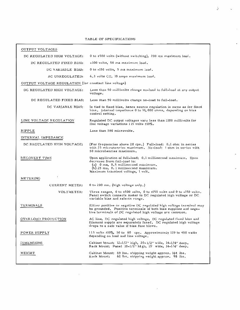
TABLE OF SPECIFICATIONS
OUTPUT VOLTAGES
I,
DC REGULATED HIGH VOLT AGE:
DC REGULATED FIXED BIAS:
DC VARIABLE BIAS:
AC UNREGULATED:
o to +500 volts (without switching), 200 ma maximum load.
-300 volts, 50 ma maximum load.
o to -150 volts, 5 ma maximum load.
6.3 volts CT, 10 amps maximum load.
OUTPUT VOLTAGE REGULATION (for constant line voltage)
DC REGULATED HIGH VOLT AGE:
DC REGULATED FIXED BIAS:
DC VARIABLE BIAS:
LINE VOLTAGE REGULATION
RIPPLE
INTERNAL IMPEDANCE
DC REGULATED HIGH VOLTAGE:
RECOVERY TIME
METERING
CURRENT METER:
VOLTMETER:
TERMINALS
OVERLOAD PROTECTION
POWER SUPPLY
DIMENSIONS
WEIGHT
Less than 50 millivolts change no-load to full-load at any outputvoltage.
Less than 50 millivolts change no-load to full-load.
Is tied to fixed bias, hence source regulation is same as for fixedbias. Internal impedance 0 to 10, 000 ohms, depending on biascontrol setting.
Regulated DC output voltages vary less than ±l00 millivolts forline voltage variations 115 volts ±1O%.
Less than 500 microvolts.
(For frequencies above 20 cps.) Full-load: 0.1 ohm in serieswith 25 microhenries maximum. No-load: 1 ohm in series with50 microhenries maximum.
Upon application of full-load: 0.1 millisecond maximum. Upondecrease from full-load to:
(a) 0 ma, 0.5 millisecond maximum.(b) 25 ma, O. 1 millisecond maximum.
Maximum transient voltage, 1 volt.
o to 200 ma. (high voltage only.)
Three ranges, 0 to +500 volts, 0 to +150 volts and 0 to -150 volts.Panel switch connects meter to DC regulated high voltage or DCvariable bias and selects range.
Either positive or negative DC regulated high voltage terminal maybe grounded. Positive terminals of both bias supplies and negative terminals of DC regulated high voltage are common.
AC line, DC regulated high voltage, DC regulated fixed bias andfilament supply are separately fused. DC regulated high voltagedrops to a safe value if bias fuse blows.
115 volts ±10%, 50 to 60 cps. Approximately 120 to 450 wattsdepending on load and line voltage.
Cabinet Mount: 12-1/2" high, 20-1/2" wide, l4-l/4"_deep.Rack Mount: Panel 10-1/2" high, 19" wide, 14-1/4" deep.
Cabinet Mount: 6!1lbs. shipping weight approx. 104 lbs.Rack Mount: 62 lbs. shipping weight approx. 98 lbs.

SECTION I
GENERAL DESCRIPTION
CAUTION
Voltages which are dangerous to lifeare present at the terminals andwithin this instrument.
1-1 GENERAL
The Model 7l2B Power Supply is a very stablesource of continuously variable direct current for plate and bias circuits. It also provide s up to 10 amper es, 6.3 volts alternating curr ent for filament cir cuits • A tworange voltmeter and a milliammeter (highvoltage only) are provided to measure thedirect current output. This power supply isveryusefulas apower sourcefor small transmitters, oscillators, complex systems, certain types of klystrons, and general laboratory use.
CAUTION
The AC power should be turned onfor at least 30 seconds before switching on the high voltage. This allowsthe regulator circuits to reach theirproper operating point and avoidsexces sive voltage at the high voltageterminals.
1-2 INSPECTION
This instrument was thoroughly tested andinspected before being shipped and is readyfor use when received.
After the instrument is unpacked, it shouldbe inspected for damage received in transit.If any shipping damage is found, follow theprocedure outlined in the "Claim for Damagein Shipment" page at the backof this instruction manual.
1 -1

SECTION II
OPERATING INSTRUCTIONS
2-1 CONTROLS AND TERMINALS
AC POWERThis toggle switch controls the power supplied to the instrument from the power line.When the switch is in the ON position thered indicator lamp above the switch willglow.
LINE 4 AMPThe fus eholder, located on the control panel,contains a 4 ampere cartridge fuse for theprotection of the whole instrument. Thefuse may be replaced by turning the fuseholder cap, removing the old fuse, and inserting a new fuse. Replacement fuses forthis instrument must be of the "Slo-Blo"type as specified in the Replaceable PartsList.
-300V 1/16 AMPThe fus eholder, located on the control panel,contains a 1/16 ampere cartridge fuse forthe protection of the -300 volt fixed biassupply. The fus e may be replaced by turning the fuseholder cap, removing the oldfuse, and inserting a new fuse.
NOTE
If this fuse blows, the positivehigh - voltage regulator circuitwill drop the HV voltage level toless than 100 volts, thus protecting external equipment or circuits against the pos s ibility ofdamage due to loss of bias •. Whenthe openfuse is replaced, all circuits restore to normal.
+HV 1/2 AMPThe fus eholder, located on the control panel,contains a .5 amper e cartridge fus e for theprotection of the high voltage de cir cuit.The fuse may be replaced by turning thefuseholder cap, removing the old fuse, andinserting a new fuse.
2-1
CAUTION
If this fuse blows, immediatelyturn off the AC POW ER switch,and then replace the fus e. Continued operation of the instrumentwith the +HV 1/2 AMP fuse openwill damage the screen grids ofthe series regulator tubes (V3,V4, V5, V6).
HIGH VOLTAGEThis toggle switch turns the high voltagedirect current off and on. The switch alsocontrols the red indicator light above it onthe control panel. When the switch is on,the indicator lamp glows as a warning thatthe high voltage is turned on.
6.3V AC, 10 AMPThe two fuseholders, located on the controlpanel, each contain a 15 ampere cartridgefus e for protection of the 6.3 volt AC filament supply circuit. Each fuse may be replaced by turning its fus eholder cap, removing the old fuse, and inserting a newfuse. Replacement fuses must be of the"Slo-Blo" type as specified in the Replaceable Parts List.
6.3V AC 10 AMP CTThese binding posts are terminals for theunregulated AC filament supply.
6.3V AC 10 AMPThese are the terminals for the 6.3 voltunr egulated alternating current.
CTThis binding post is the terminal for thecenter tap of the secondary winding fromwhich the unregulated AC is taken.
-300V 50 MA 5 !vIA GNDThese binding posts are terminals for thebias supply output and chassis ground.
-300V 50 MAOutput terminal for the fixed -300V regulated voltage supply.

5 MAOutput terminal for the variable (0-150volt) regulated bias voltage supply.
GNDTerminal for making connection to thechassis. Anyone of the output terminalsmay be connected to the chassis by connection to terminal GND.
COM +HV GNDThese binding posts are terminals for thehigh voltage supply, common conductor,and chassis ground.
+HVOutput terminal for the regulated 0-500volt voltage supply.
COMOutput terminal common to the HV, 5 MA(variable bias), and -300V 50 MA (fixedbias) cir cuits •
GNDTerminal for making connection to thechassis.
-BIAS CONTROLThis control varies the output of the regulated bias voltage supply from 0 to 150 volts.
HV CONTROLThis control varies the output of the regulated high voltage supply from 0 to 500 volts.
METER RANGEThis switch connects the regulated highvoltage supply circuit to the voltmeter oneither the 0-150V or 0-500V range. Operation of the switch to 0-150 -BIAS connectsthe variable bias supply circuit to the voltmeter.
2-2 OPERATION
CAUTION
Avoid electric shock by turning thehigh voltage switch to the off position before making any connectionsto the instrument.
2-2
The procedure for operating the Model 712BPower Supply is as follows:
a. Connect the power cable to aIlS V powerline and turn the AC POWER switch to
ON.
NOTE
The triple -conductor power cable issupplied with the new NEMA approved three-prong plug. The third conductor provides a chassis ground.An adapter may be obtained to permit use of this plug with two-conductor receptacles.
b. With the HIGH VOLTAGE switch in theoff position, connect the output terminals
to the load.
c. If the bias supply is to be us ed, set theMETER RANGE switch to the 0-150V
-BIAS position and adjust the -BIAS CONTROLfor the desired voltage.
NOTE
The internal impedance of the variable bias circuit can be as high as10, 000 ohms, depending on the setting of -BIAS CONTROL.
d. Set the METER RANGE switch at the 0150V or 500V position, and adjust the
HV C ONTR OL for the des ired output voltage.
e. Turn the HIGH VOLTAGE switch to ON,check the bias voltage, and readjust -BIAS
CONTROL if necessary.
f. If the Model 712B is to be used for anapplication which requires a power sup
ply of more than 500 volts, up to 300 voltsadditional may be made available by connecting the load across +HV and -300V 50 MA.Ground may be connected to either terminal,as desired.
SECTION III
CIRCUIT DESCRIPTION
3-1 GENERAL
The Model 7l2B Power Supply furnishes twoseparate regulated supplies: a positive highvoltage in the 0-500 volt range and a biasvoltage. A block diagram of the Model 7l2Bis shown in Figure 1 •
Voltage level of the high voltage supply is adjusted by means of a panel knob, HV CONTROL, which controls the setting of variableautotransformer Tl. The autotransformersupplies primary voltage to the high voltagepower transformer, T2. The comparis.onvoltage in the regulator circuit is adjusted bymeans of variable resistor R39 which is mechanically coupled to the autotransformershaft. This arrangement maintains the regulator circuit at its optimum operating point,regardless of output voltage level.
After the high voltage has been rectified (dualdiodes VI and V2) and filtered, it is appliedto a group of series regulator tubes (pentodesV3-V6), to the DC milliammeter, and thento the high voltage output terminal, +HV. Theconduction of the series regulator tubes iscontrolled by a cascade differential amplifier(dual triodes V12 and V13). The differentialamplifier compares a sample of the outputvoltage with the voltage developed acrossvoltage reference tube VII; any differencebetween thes e voltages is amplified and theconductivity of the series regulator tubes ischanged accordingly.
The fixed bias voltage (-300V) supply consists of a conventional power transformer,full-wave rectifier (dual diode V7), and capacitor -input filter. The voltage is regulatedby means of a series regulator tube (pentodeVB), which is controlled in turn by a cascadedifferential amplifier (dual triodes V9 andVlO). Operation of the regulator circuit issimilar to the +HV regulator described above.
A source of variable bias voltage is providedby means of a voltage divider (variable resistor R46) which is connected between the-300V 50 MA terminal and the COM terminal.This voltage is regulated against line voltagevariations only. Since the internal impedance
may be as high as 10, 000 ohms, dependingupon the setting of resistor R46, the voltagewill depend upon the actual load current being drawn (5 rna. max.). This voltage canbe measured by turning the METER RANGEswitch to the -150 V -BIAS position.
3-2 HIGH VOLTAGE REGULATOR CIRCUIT
The regulator circuit is so arranged that aslight voltage change in the sampled outputin the positive directionwill result in a relatively large voltage swing in the negative direction on the grids of the series regulatortubes, and vice versa.
Figure 2 shows the arrangement of dual triodes V13 and V12 which, connected in cascade,form a two stage differential amplifier. Ineach tube, cathode connections are commonfor the two sections. Thus any variation inplate current in one section appears acrossthe cathode resistor common to both sections,and results in a difference voltage in each ofthe output circuits.
In the first stage, a fixed bias supplied byvoltage reference tube VII is applied to onegrid of dual triode V13. The bias on the othergrid of V13 is a portion of the +HV voltage,sampledwithrespectto the -300voltbias sup-.ply through a voltage divider. Any variationin the level of the output voltage results involtage changes in the plate circuits of bothsections of V13, and corresponding changesin the bias es on the grids of dual triode VIZ inthe next stage.
For example, if the voltage of the sampledoutput swings in the positive direction, increased current will flow through the righthand section of V13, which will raise the cathode voltage and lower the right-hand plate(pin 1) voltage. Since the bias on the grid inthe left-hand section of V13 remains fixed,the increas ed cathode voltage will decreaseconduction in the left-hand half of the tube,which result in an increase in voltage on theleft-hand plate (pin 6).
3-1

/OUTPUT I--~_-o_ + HV
CURRENT
HIGHVOLTAGESUPPLY
HVCONTROL
~------------------------~
ISERIES !
1 '.REGULATOR I""'--+......... ~r---..&.-__ ~
VARIABLE..- I--
TRANSFORMER
DIFFERENTIALr--o+- AMPLIFIER ~
POWERINPUT
115V5O-IOOO/V
VOLTAGEREFERENCE
TUBE
DIFFERENTIAL
~ AMPLIFIER
/OUTPUT
VOLTAGE
--
+-300VOLT
SUPPLY
SERIES
REGULATOR__._......-------+--00_ COM
~">4o-------4II~O_ 5 MAo -BIAS CONTROL
lGND
- -300V- - 50MA
- 6.3V AC_ CT
IOAMP
-
'FILAMENT
TRANSFORMER......--------------------0
Figure 1. Model 7l2B Block Diagram
3-2

In the second stage, the right-hand section ofdual triode VIZ acts as a cathode follower toincrease the signal on the grid of the lefthand section. The plate circuit in the lefthand section supplies the bias for the gridsof the series regulator tubes. The plate circuits of the two sections of VIZ are crosscoupled. This arrangement results in greater amplifier gain and sensitivity.
To ensure that the series regulator tubes willhave sufficient conductivity to maintain regulation under transient conditions, a separatescreen voltage supply from selenium rectifier SRI is provided for the regulator tubes.
The voltage divider in the voltage comparison circuit provides separate paths to thesignal grid of dual triode V13 for high-frequency and low-frequency voltages. to makethe response of the regulated supply fast athigh frequencies and yet very stable. At about 1, 000 cycles, AC components are coupled to the grid via resistor R38 and capacitor C4. DC components pass to the gridthrough a resistor network (R38, R39, R40,R4l) •
3-3
3-3 BIAS SUPPLY CIRCUIT
Arrangement and operation of the regulatedbias supply circuit is similar to that of theplate voltage supply circuit except that primary current to the bias supply transform.er,T3, is not variable. The bias supply seriesregulator tube, V8, is controlled by a differential amplifier (dual triodes VlO and V9).The comparison voltage for the circuit isfurnished by voltage reference tube VII, andthe sample voltage is sampled with respectto COM th~ough a voltage divider which includes variable resistor RZ4. The fixed biasvoltage is brought out to binding post -300V50 MA on the control panel.
A variable bias voltage is available at binding post 5 MA. The voltage level of the variable bias supply may be adjusted by means ofthe -BIAS CONTROL knob on the front panel.The control varies the setting of variable resistor R46 in the voltage divider across thebias supply output circuit.

3
R6R36
R45
M2
R38
R39
R40
R34 R35
2
Vl3 R42
1-300V I50MA
Figure 2. Partial Schematic of High Voltage Supply Regulator Circuit
3.4

CAUTION
SECTION IV
MAINTENANCE
Tubes
Voltages which are dangerous to lifeare present within the instrument.Disconnect the power cable from thepower line before removing the coveror bottom plate.
4-1 COVER AND BOnOM PLATE REMOVAL
Rack Model
To remove the cover, unscrew the four screwswhich fasten the cover to the back of the instrument, and slide the cover toward the rearof the instrument. To remove the bottomplate, unscrew the four screws which fastenthe plate to the bottom of the instrument, andlift off the plate.
Cabinet Model
a. On the rear of the instrument, removethe four screws which fasten the rear
cover to the chassis. Remove the rear cover.
b. Turn the instrument on its back.
c. Remove the two3/16inchAllensetscrewson the bottom, next to the control panel.
d. Lift the cabinet off the instrument.
4-2 REPLACEMENTS
Variable Transformer Brush
Inspect the brush contact at periodic intervals.1£ the brush contact on transformer TI beginsto show excessive wear, purchase a new brushassembly, for a Type 20 variable transformer, from the" Superior Electric Co., Bristol,Conn. The brush contact is made of specialmaterial and ordinary carbon will not function. Fit the brush to the commutator bysanding with fine crocus cloth. Carbon particles must be blown off the commutator afterfitting the brush.
Any tube in the Model 712B may be replacedwith a tube having corresponding RETMAstandard characteristics.
All tubes are accessible when the cover plateor cabinet is removed. Location of tubes isshown in Figure 3.
Tubes V3, V 4, V5, or V6 may be replacedwith a 6L6, 6L6-G, 6L6-GB or 5881.
Replacement of tube VII may make it necessary to readjust the output voltage of the fixed, -300 volt bias ~upply (see Adjustments,paragraph 4-3).
Replacement of tube VIO may make it necessary to readjust the bias supply line regulation (see Adjustments, paragraph 4-3).
Replacement of tube Vl3 may make it necessary to readjust the HV supply line regulation (see Adjustments, paragraph 4-3).
1£ ripple is present in the regulated voltageafter replacement of tube V9, VIO, Vl2, orV13, probably it is due to excessive heatercathode leakage in the replacement tube.
Variable Resistors
Connections to all variable resistors areshown in Figure 5.
Resistor R39 is ganged on the shaft with variable transformer T1. Its location, behindthe control panel, is shown in Figure 3. Theprocedure to be followed after a replacementof variable resistor R39 is described underAdjustments, paragraph 4-3. The locationof resistor R46, which is adjusted by the-BIAS CONTROL knob, also is shown in Figure 3.
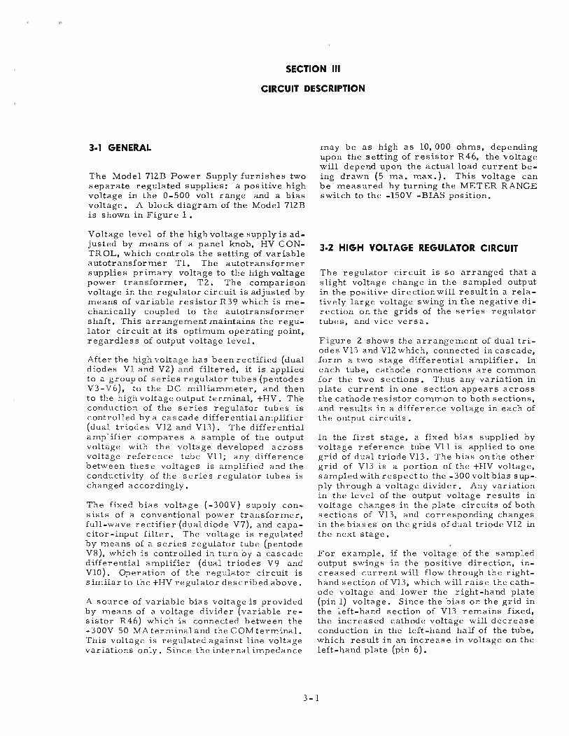
Location of resistors R40, R42, R24, RIO,and R8 on the bottom of the instrument areshown in Figure 4.
1£ resistor R24 is replaced, readjust the levelof the fixed -300 volt bias supply (see Adjustments, paragraph 4-3).
4-1

~ I tv
Fig
ure
3.
Mo
del
7l2
BT
op
Vie
wC
ov
er
Pla
teR
em
ov
ed
"

MODEL 712 B
If resistor R42 or resistor R40 is replaced,readjust the maximum and minimum levelsof the HV supply output voltage (see Adjustments, paragraph 4-3).
If resistor R8 is replaced, readjust the biassupply line regulation, and if resistor RIO isreplaced, readjust the HV supply line regulation (see Adjustments, paragraph 4-3).
Lamps
If either the AC POWER or HIGH VOLTAGElamp should burn out, replace with the 6volt lamp specified in the Replaceable PartsList. The lamps are of the bayonet type andare plugged into sockets accessible from thefront of the control panel. To remove a burned out lamp:
a. Turning in a counterclockwise direction,unscrew the lamp cap and remove it.
b. Firmly press the light bulb into the socket, and then give the bulb a twist in the
counterclockwise direction to free it. Pickthe bulb out of the socket.
4-] ADJUSTMENTS
Auxiliary Equipment Required
1 - variable transformer1 - AC voltmeter 0 -150 ) Hewlett-Packard
volts ) Model 4l0B or1 - DC voltmeter 1000) equal.
volt range )1 - High impedance vacuum)
tube voltmeter )1 - 300 volt battery
ACVOLT
METER
VARIABLETRANSFORMER
NOTE
The settings of variable resistor R39and the HV C ONTR OL stop ar e setat the factory, and should never betouched in the field unless transformer Tl or R39 should require replacement. Adjustment proceduresto be performed in the event of thereplacement of either component aregiven at the end of this Adjustmentsparagraph. If either Tl or R39 isreplaced, its respective adjustmentprocedure should be performed before making the line regulation oroutput voltage adjustments.
4-4 LINE REGULATION ADJUSTMENT
To adjust the Model 7l2B line regulation, itis necessary to have (1) a stable source ofDC voltage for comparison purposes, (2) avariable transformer, and (3) a sensitivevoltmeter (1.0 volt full scale) with an inputresistance of 1 megohm or greater (Model4l0B). A convenient test set-up for measuring line regulation is illustrated below. Connections shown at the Model 7l2B are thoseused when measuring and adjusting the HVsupply line regulation.
Adjustment of Bias Supply Line Regulation
a. Make connections as shown in the testset - up below, except that the positive
side of the battery is to be connected to theC OM terminal on the Model 7l2B control paneland the negative terminal of the VTVM is tobe connected to the -300V 50 MA terminal.
V.T.V.M.0-1 V
4-3
~ I ~
Fig
ure
4.
Mo
de1
7l2
BB
ott
om
Vie
wB
ott
om
Pla
teR
em
ov
ed

b. Set the variable transformer to l03voltsand allow about 15 seconds for the cir
cuit to stabilize. Note the reading of theVTVM.
c. Change the variable setting to 128 volts.Mter about 5 seconds the VTVMwill in
dicate a temporary slow drift in the -300 voltsupply voltage. When the circuit again stabilizes, note the new reading of the VTVM.
d. If the new reading of the VTVM differsby more than. 01 - .02 volt, adjust vari
able resistor R8 (see Figure 4), and repeatsteps band c.
f. Repeat steps b - d until the -circuit stabilizes to within .01 - .02 volt for line
voltage changes of 103-128 volts.
Adjustment of HV Supply Line Regulation
a. Make connections as shown on the suggested test set-up below.
b. The procedure is the same as for measuring and adjusting the bias supply line
regulation except that variable resistor RIOis adjusted to stabilize the HV supply circuit.
4-5 ADJUSTMENT OF FIXED -300 VOLTBIAS SUPPLY OUTPUT VOLTAGE
a. Check that the Model 7l2B power cable isdisconnected from the power sour ce.
Remove the cover and bottom plates. Placethe instrument on its back so that both thefront panel and the under side of the instrument will be accessible.
b. Attach a DC voltmeter (Model 4l0B) between the COM and -300V 50 MA termi
nals on the control panel.
c. Connect a variable transformer betweenthe power source and the Model 7l2B
power cable. Turn the AC POWER switch toON, and allow the instrument to warm up forabout one minute. Adjust the variable transformer so that 115 volts is applied to theModel 712B.
d. Adjust variable resistor R24 until thetest voltmeter reads -300 volts.
4-5
4-6 ADJUSTMENT OF HV SUPPLY OUTPUTVOLTAGE
a. Set up the instrument as in steps a and cof the previous adjustment procedure.
b. With the METER RANGE switch in the0-500V position and the HV CONTROL
in its maximum clockwise position, adjustvariable resistor R42 (see Figure 4) until theDC voltmeter on the control panel reads +500.
c. Rotate the HV CONTROLto its maximumcounterclockwise position (minimum out
put) and switch the METER RANGE switch tothe 0-150Vposition. Adjust variable resistorR 40 until the DC voltmeter reads 0 volts.
d. Since the settings of R40 and R42 areinterdependent, it may be necessary to
repeat steps band _c several times.
NOTE
The indicated meter zero could beoff a volt or so due to change in meter position when instrument is onits back.
4-7 SEnlNG VARIABLE RESISTOR R39
This adjustment is to be made only if variable resistor R39 or transformer Tl has beenreplaced. Resistor R39 is mechanically coupled to the shaft of the variable transformerTl. The assembly is located behind the control panel (see Figure 3) above the deck, andis accessible when the cover plate is removed.
a. Check that the power cable is disconnected down from the power source.
b. With an Allen wrench loosen the two set-screws which secure the ~oupling to the
transformer shaft. (Do not loosen the sets crews which secure the coupling to the resistor shaft.)
c. Set the HV CONTROL to its maximumcounterclockwise position. Set the ME
TER RANGE switch to the 0-150V -BIAS position.
d. Connect an ohmmeter across the R39lead.

R38
PIN 2VI3
R41
R45
PIN 2VIO
TERM.D5T5
RI
SRi
Figure 5. Model 7l2B Detail of Variable Resistors and Selenium Rectifier
4-6

e. By means of the coupling, adjust the position of the resistor shaft until an ohm
meter reading of £lli ohms is obtained.
f. Hold the shaft in this position, and tighten the setscrews which secure the cou
pling to the transformer shaft. Remove theohmmeter.
g. Check and if necessary readjust the levelof the HV output as described in Adjust
ment of HV Supply Output Voltage, paragraph4-6.
4-8 SEnlNG THE STOP ON THE HVCONTROL
This adjustment is to be made only if variable transformer Tl has been replaced. Themovable stop is a small "C II clamp which isattached to the wiper ring on the back of thevariable transformer.
a. Check that the power cable is dis connected from the power source.
b. Use an Allen wrench to loosen the setscrew which secures the stop to the rim
of the transformer wiper ring, and removethe stop.
4-7
c. Attach a DC voltmeter (Model 4l0B, 1,000volt range) oetween terminal COM on the
control panel an4 socket pin 3 of tube V3.
d. Plug the Model 7l2B power cable into avariable transformer set for 115 volts
(measured) •
e. Turn off the HIGH VOLTAGE switch.Set the METER RANGE switch at 0-500V
and the HV C ONTR OL to its maximum counterclockwise position. Turn the AC POWERswitch to ON, and allow at least a 3D-secondwarm-up.
f. Advance the HV CONTROL in a clockwise direction until the test voltmeter
reads +380 volts.
g. Turn off the AC POWER switch, dis con-nect the Model 7l2B power cable and at
tach the stop to the transformer wiper ringso that the movable stop rests against thestationary stop in such a manner that the HVCONTROL cannot return in a counterclockwise direction. Note that the stop sets theminimum voltage applied to the series regulator tubes.
h. Remove the voltmeter.
i. Check the setting of variable resistorR39, as described above.

TROUBLE SHOOTING CHART
The following information is designed to aid in trouble shooting a defective instrument:
SYMPTOMS
Instrument NOToperating, pilotlight NOT on.
Instrument NOToperating, pilotlight ON.
POSSIBLE CAUSE
Line fuse Fl blowndue to defective fuseor overload in eitherpower supply.
Defective tube orcomponent causingimproper operation.
TEST PROCEDURE
Replace fuse. If this fuse blows, remove tubes VI, V2, and V7, and againreplace fuse Fl. If this fuse blows,it indicate s:
1. Short circuit in wiring associatedwith power transformer T2 or T3.
2. Short circuit in filament wiring.
3. Transformer T2 or T3 is defective.
If fuse does not blow when rectifyingtubes are removed, it indicates:
1. Defective filter capacitor.
2. Short circuit in a tube.
3. Short circuit in the direct currentwiring.
To localis e the circuit in trouble,measure the DC resistance across theoutput from each of the three rectifiers. Disconnect the instrument fromthe power line before making the measurements.
Normal DC Resistances Across PowerSupply Circuits:
Recti- Connect Ohm- Approx.Normalfier meter Across Resist. (Ohms)
VI, V2 Socket pin 8, 50KVI or V2, andterm. COM
V7 Socket pin 8 2MV7, and term.-300V 50 MA
SRI Terms. of 1.5Mcapacitor C9(connect meterneg. lead tojunction of C 9and R13)
Set METER RANGE switch at 0-150V-BIAS and turn -BIAS CONTROL to itsmaximum clockwise position. If voltmeter on control panel does not deflect;or reads les s than 150 volts, trouble isin bias supply circuit. Check bias supply DC voltages against those indicatedon schematic diagr am (should agr eewithin ±10%).
4-8
REMEDIES
1. Locate and clearshort circuit.
2. Locate and clearshort circuit.
3. Replace defectivetransformer.
1. Locate and replacedefective capacitor.
2. Locate and replacedefective tube.
3. Locate and clearshort circuit.
Locate defective component, and replace.

SYMPTOMS POSSIB LE CAUSE TEST PROCEDURE
If voltmeter reads -150 volts or more,trouble probably is in BV supply circuit. Set METER RANGE switch at0-500V and turn HV CONTROL tomaximum clockwise position. If voltmeter does not deflect, trouble is inHV supply circuit, and DC voltagesshould be checked against those shownon the schematic. If voltmeter readsless than 500 volts, trouble may be ineither regulator circuit.
REMEDIES
Locate defective component, and replace.
Instrument oper - Defective fus e, orating, but output defective tube (orvoltage deviates associated component)from desired in regulator circuit,level: as. detailed below:
High Voltagefu!E.E1yVoltage slightly Fuse F2 (+HV) blownnegative
Voltage low Fuse F5 (-300V)blownVIOV9Vl3
V oltage high VIIV12V7V8
-300V BiasSupplyVoltage slightlypositive V8
V7
Voltage low VII
Voltage high V9VIO
Check for open fuse.
1. Check for open fuse.
2. Check for burned-out tube.
3. If all tubes are operating, checkdefective tube in suspected circuitby substituting tube known to begood.
4. Test external components in suspected tube circuit.
1. Check for burned-out tube.
2. If all tubes are operating, checkfor defective tube in suspectedcircuit by substituting tube knownto be good.
3. Test external components in suspected tube circuit.
4-9
Replace blown fuse.
1. Replace blown fuse.
2. Replace burned-outtube.
3. Replace any defective tube.
4. Replace any defective component.
1 • Replace burned-outtube.
2. Replace any defective tube.
3. Replace any defective component.

CD
oIHIG
H~~LTAGEI
l-r'i2
B-E
-,ot-
,
I>f
0-"0
R3
85
2A
0~
10
00
IDC
MIL
LA
MP
ER
ES
I
NO
TES
CO
ND
ITIO
NS
OF
DC
VO
LTA
GE
ME
AS
UR
EM
EN
TL
LIN
EV
OLT
AG
EA
T11
5V
OLT
S.
50
/'1
00
0",
2.N
OE
XT
ER
NA
LLO
AD
3.C
OM
.C
ON
NE
CT
ED
TOG
ND
.4
.H
IGH
VO
LTA
GE
ON
5.
HV
CO
NT
RO
LS
ET
FOR
+5
00
DC
VO
LTS
6.V
OLT
AG
ES
ME
AS
UR
ED
BE
TW
EE
NIN
DIC
AT
ED
PO
INT
SA
ND
CH
AS
SIS
WIT
HV
OLT
ME
TE
RH
AV
ING
122
ME
GO
HM
INP
UT
RE
SIS
TA
NC
EC
ON
OlT
ION
SO
FA
CV
OLT
AG
EM
EA
SU
RE
ME
NT
I.T
HR
U~
SA
ME
AS
DC
CO
ND
ITIO
NS
6.V
OLT
AG
ES
ME
AS
UR
ED
BE
TW
EE
NIN
OIC
ATE
DP
OIN
TS
WIT
HA
10
00
OH
MI
VO
LTO
RB
ET
TE
RA
CV
OLT
ME
TE
RA
LL
CA
PA
CIT
AN
CE
INw
F.R
ES
IST
AN
CE
INO
HM
SU
NLE
SS
OTH
ER
WIS
EN
OT
ED
OI?lPA~~S
CONT:~LII
M~~Mi'-::1S
""CR:
:-::E"
'"WQR
=IVE=
"R-:A
""D~J.
I~
•C
HA
SS
IS
7r28
R3
63
90
K
+$
00
+6
8$
+~60
R6
15
00
OF
MO
DE
LA
BO
VE
CO
PY
RIG
HT
19
54
BY
HE
WL
ET
T-P
AC
KA
RD
Thi
sdr
awln
QII
Inte
nded
for
'he
op
.ro
tio
nan
d
mal
ntt
l'lo
nee
at
He
wle
tt-P
ac
ka
rdeq
uip
men
ta
nd
'sn
ot
tobe
used
oth
erw
ise
orre
pro
du
ttd
with
out
wri
tten
con
sen
to
fth
eH
ew
lett
-P
ac
ka
rdC
om
po
ny
SC
HE
MA
TIC
DIA
GR
AM
SE
RIA
L51
1a
+1
00
0
RI
25
K
CI
15~F
LI
5H
VI
5R
4G
Y
V2
5R
4G
Y
T2

SECTION V
TABLE OF REPLACEABLE PARTS
NOTE
Any changes in the Table of Replaceable Parts will belisted on a Production Change sheet at the front of thismanual.
When ordering parts from the factory always includethe following information:
Instrument model numberSerial number-hp- stock number of partDescription of part

TABLE OF REPLACEABLE PARTS
CircuitRef.
C1
C2
C3
C4
C5
C6,C7
C8
C9, C10
C11
C12
C13
C14
C15
R1, R2
R3, R4,R5, R6
R7
R8
R9
Description
Capacitor: fixed, paper,15 ~, +40%, -15%, 1000 vdcw
Capacitor: fixed, paper,• 01 ~, ±10'0, 1600 vdcw
Capacitor: fixed, paper,4~, ±10%, 600 vdcw
Capacitor: fixed, oil filled paper,•4~, ±10%, 100 vdcw
Capacitor:. fixed, .paper,1~, ±100/0, 600 vdcw
Capacitor: fixed, paper,4~, ±100/0, 600 vdcw
Capacitor: fixed, paper,.1~, ±100/0, 400 vdcw
Capacitor: fixed, paper,4~, ±100/0, 600 vdcw
Capacitor: fixed, paper,• 5 ~, ±100/0• 400 vdcw
Capacitor: fixed, silver mica,510 ~, ±50/0, 500 vdcw
Capacitor: fixed, paper,.1~, ±100/0, 400 vdcw
Capacitor: fixed, mica,150 ~~, ±100/o, 500 vdcw
Capacitor: fixed, paper,• 0047 ~, ±200/o, 6000 vdcw
Resistor: fixed, wirewound,25, 000 ohms, ±100/o, 20 W
Resistor: fixed, composition,1500 ohms, ±100/o, 1/2 W
Resistor: fixed, composition,390 ohms, ±10%, 1 W
Resistor: variable, wirewound,100 ohms, linear taper
Resistor: fixed, composition,390 ohms, ±100/o, 1 W
-hpStock No.
17-46
16-56
17-10
16-72
17-12
17-10
16-35
17-10
16-58
15-27
16-35
14-150
16-75
27-31
23-1500
24-390
210-4
24-390
Mfr. * ~ Mfrs.Designation
CCCP70E1EG156X
CC73P103916
PT-64
PMT-4G
N23F467
PT-64
CC67P10494
PT-64
Z300405
AType 1479
CC67P10494
VType OXM
CC84P472060
SType 2R
BEB 1521
BGB 3911
HP
BGB 3911
*See "List of Manufacturers Code Letters For Replaceable Parts Table."5-2
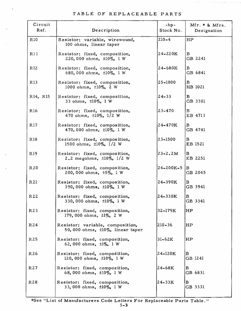
TABLE OF REPLACEABLE PARTS
Circuit -hp- Mfr. * & Mfrs.Ref. Description Stock No. De s ignation
RIO Resistor: variable, wirewound, 210-4 HP100 ohms, linear taper
R11 Resistor: fixed, compos it ion, 24-220K B220, 000 ohms, ±100/0, 1W GB 2241
R12 Resistor: fixed, compos ition, 24-680K B680, 000 ohms, ±100/0, 1W GB 6841
R13 Resistor: fixed, compos ition, 25-1000 B1000 ohms, ±100/0, 2W HB 1021
R14 11 R15 Resistor: fixed, compo s ition, 24-33 B33 ohms, ±100/0, 1 W GB 3301
R16 Resistor: fixed, composition, 23-470 B470 ohms, ±100/0, 1/2 W EB 4711
R17 Resistor: fixed, compos ition, 24-470K B470, 000 ohms, ±l'O%, 1W GB 4741
R18 Resistor: fixed, compos ition, 23-1500 B1500 ohms, ±100/0, 1/2 W EB 1521
R19 Resistor: fixed, compos ition, 23-2.2M B2.2 megohms, ±100/0, 1/2 W EB 2251
R20 Resistor: fixed, compos ition, 24-200K-5 B200, 000 ohms, ±50/0, 1W GB 2045
R21 Resistor: fixeq, compos ition, 24-390K B390, 000 ohms, ±100/0, 1W GB 3941
R22 Resistor: fixed, compos ition, 24-330K B330, 000 ohms, ±100/0, 1W GB 3341
R23 Resistor: fixed, compos ition, 32-179K HP179, 000 ohms, ±10/0, 2W
R24 Resistor: variable, composition, 210-36 HP50, 000 ohms, ±100/0, linear taper
R25 Resistor: fixed, composition, 31-62K HP62, 000 ohms, ±10/0, 1 W
R26 Resistor: fixed, compos ition, 24-120K B120, 000 ohms, ±100/0, 1W GB 1241
R27 Resistor: fixed, compos ition, 24-68K B68, 000 ohms, ±100/0, 1 W GB 6831
R28 Resistor: fixed, compos ition, 24-33K B33, 000 ohms, ±100/0, 1W GB 3331
*See "List of Manufacturers Code Letters For Replaceable Parts Table."5-3

TABLE OF REPLACEABLE PARTS
CircuitRef. Description
-hpStock No.
Mfr. * & Mfrs.Designation
R29 Resistor: fixed, composition,80, 000 ohms, ±10/0, 1 W
R30 Resistor: fixed, composition,120, 000 ohms, ±100/0, 1 W
R31, R32 Resistor: fixed, composition,330, 000 ohms, ±100/0, 1 W
31-80K
24-120K
24-330K
HP
BGB 1241
BGB 3341
R33 Resistor: fixed, composition,200, 000 ohms, ±50/0, 1 W
24-200K-5 BGB 2045
R34 Resistor: fixed, composition,3 megohms, ±50/0, 1/2 W
23-3'M-5 BEB 3055
R35 Resistor: fixed, composition,1.5 megohms, ±50/0, 1/2 W
23-1.5M-5 BEB 1551
R36
R37
R38
R39
R40
R41
R42
R43
R44
Resistor: fixed, composition,390, 000 ohms, ±100/0, 1 W
Resistor: fixed, wirewound,.6 ohms, ±100/0, 2 W
Resistor: fixed, composition,1000 ohms, ±100/0, 1 W
Resistor: variable, composition,500, 000 ohms, ±100/0, linear taper
Resistor: variable, composition,50, 000 ohms, ±100/0, linear taper
Resistor: fixed, composition,83, 000 ohms, ±10/0, 1 W
Resistor: variable, composition,50, 000 ohms, ±100/0, linear taper
Resistor: fixed~ composition,37, 000 ohms, ±10/0, 1 W
Resistor: fixed, composition,150, 000 ohms, ±100/0, 1 W
24-390K
26-39
24-1000
210-59
210-36
31-83K
210-36
31-37K
24-150K
BGB 3941
IType FYG
BGB 1021
HP
HP
HP
HP
HP
BGB 1541
R45 Resistor: fixed, composition,1.5 megohms, ±50/0, 1/2 W
23-1.5M-5 BEB 1551
R46
R47
Resistor: variable, wir ewound,25, 000 ohms, ±100/0, linear taper
Resistor: fixed, wirewound,10, 000 ohms, ±100/0, 10 W
210-10
26-10
I58-25000
SType 1-3/4E
*See "List of Manufacture'rs Code Letters For Replaceable Parts Table."5-4

TABLE OF REPLACEABLE PARTS
CircuitRef.
R48
F1
F2
F3, F4
F5
II, 12
FAN
M1M2
PI
L1L2
SlS2S3
SRI
T1T2T3
Description
Resistor: fixed, composition,220 ohms, ±10%, 1/2 W
Binding Post:Binding Post Nut:Binding Post Cap InsulatorBinding Post Insulator, BlackBinding Post Insulator, Red
Flexible Coupling:
Fuse: 4A, Withstands 2000/0 overloadfor 12 sec.
Fuse: 0.5A, 3AG
Fuse: 15A, Withstands 2000/0 overloadfor 5 sec·. min. to 60 sec. max.
Fuse: 1/8A, 3AG
Fuseho1der:
Knob: HV ControlKnob: 1-1/2" diam. meter range
-bias control
Lamp: 6V
Fan Motor:Fan Blade:
Lampho1der:
Meter: 0-150V, 0-500V, DCMeter: 0-200MA, DC
Power Cable:
Reactor: 5 H @ 225 MAReactor: 6 H @ 125 MA
Toggle Switch, SPSTToggle Switch, DPDTRotary Switch, Assem.
Rectifier, metallic:
Variable Transformer:Power Transformer:Power Transformer:
-hpStock No.
23-220
149-4149-5M-58G-83DG-83E
M-25
211-46
211-42
211-64
211-67
140-16
712B-7437-11
211-47
314-3314-7
145-2
112-26112-25
812-56
911-49911-47
310-11310-99712B-19
212-95
910-71910-111910-112
Mfr. * & Mfrs.Designation
BEB 2211
HPHPHPHPHP
HP
E, MDX-4
T, 312.500
T, 313015
E1mar, #312.125
T, 342001
HPHP
0, #47
HPHP
Signal Indicator#807BS
HPHP
HP
HPHP
D, 20994-HWD, 80421HP
Radio ReceptorType 24Y2
HPHPHP
*See "Li'st of Manufacturer. Code Letters For Replaceable Parts Table."5-5

TABLE OF REPLACEABLE PARTS
Circuit -hp- Mfr. * & Mfrs.Ref. Description Stock No. Designation
VI Tube: 5R4GY 212-5R4GY zzV2 Tube: 5R4GY 212-5R4GY zzV3, V4, Tube: 6L6GB (6L6, 6L6G, or 5881 212-6L6GB zzV5, V6 may be used)V7 Tube: 5Y3GT 212-5Y3GT ZzV8 Tube: 6W6GT 212-6w6GT zzV9 Tube: 12AX7 212-12AX7 zzVI0 Tube: 12AX7 212-12AX7 ZZVII Tube: 5651 212-5651 ZZV12 Tube: 12AX7 212-12AX7 ZZV13 Tube: 12AX7 212-12AX7 ZZ
. -
,
*See "List of Manufacturers Code Le~:.e6rs For Replaceable Parts Table."

LIST OF CODE LETTERS USED IN TABLE OF REPLACEABLE PARTSTO DESIGNATE THE MANUFACTURERS
Code Letter
ABCDEFGHHPIJKLMNoPoRSTUVWXYZAABBCCDDEEFFGGHHnJJKKLLMMNN00PP00RRSSTTUUVVWWXXYYZZ
ABACADAEAFAGAH
Manufacturer
Aerovox CorporationAllen-Bradley CompanyAmperite CompanyArrow, Hart & HegemanBussman Manufacturing CompanyCarborundum CompanyCentralabCinch-Jones Mfg. CompanyHewlett-Packard CompanyClaro stat Mfg. CompanyCornell Dubilier Elec. CompanyHi-O Division of AerovoxErie Resistor CorporationFed. Telephone & Radio CorporationGeneral Electric CompanyGeneral Electric Supply CorporationGirard-HopkinsIndustrial Produ.cts CompanyInternational Resistance CompanyLectrohm IncorporatedLittlefuse IncorporatedMaguire Industrie s IncorporatedMicamold Radio CorporationOak Manufacturing CompanyP. R. Mallory Co., IncorporatedRadio Corporation of AmericaSangamo Electric CompanySarkes TarzianSignal Indicator CompanySprague Electric CompanyStackpole Carbon CompanySylvania Electric Products CompanyWestern Electric CompanyWilkor Products, IncorporatedAmphenolDial Light Co. of AmericaLeecraft Manufacturing CompanySwitchcraft, IncorporatedGremar Manufacturing CompanyCarad CorporationElectra Manufacturing CompanyAcro Manufacturing CompanyAlliance Manufacturing CompanyAl"cO Electronics, IncorporatedAstron Corporation~el Brothers IncorporatedBelden Manufacturing CompanyBird Electronics CorporationBarber Colman CompanyBud Radio IncorporatedAllen D. Cardwell Mfg. CompanyCinema Enginee ring CompanyAny brand tube meeting RETMAcharac te r i s tics.Corning Glass WorksDale Products, Incorporated .The Drake Mfg. CompanyElco CorporationHugh H. Eby CompanyThomas A. Edison, IncorporatedFansteel Metallurgical Corporation
Address
New Bedford, Mass.Milwaukee 4, Wis.New York, N. Y.Hartford, Conn.St. Louis, Mo.Niagara Falls, N. Y.Milwaukee I, Wis.Chicago 24, Ill.Palo Alto, Calif.Dover, N. H.South Plainfield, N. J.Olean, N. Y.Erie 6, Penn.Clifton, N. J.Schenectady 5, N. Y.San Francisco, Calif.Oakland, Calif.Danbury, Conn.Philadelphia 8, Penn.Chicago 20, Ill.DesPlaine s , Ill.Greenwich, Conn.Brooklyn 37, N. Y.Chicago 10, Ill.Indianapolis, Ind.Harrison, N. J.Marion, Ill.Bloomington, Ind.Brooklyn 37, N. Y.North Adams, Mas s.St. Marys, Penn.Warren, Penn.New York 5, N. Y.Cleveland, OhioChicago 50, Ill.Brooklyn 37, N. Y.New York, N. Y.Chicago 22, Ill.Lynn, Mass.Redwood City, Calif.Kansas City, Mo.Columbus 16, OhioAlliance, OhioNew York 13, N. Y.East Newark, N. J.Long Island City, N. Y.Chicago 44, Ill.Cleveland 14, OhioRockford, Ill.Cleveland 3, OhioPlainville, Conn.Burbank, Calif.
Corning, N. Y.Columbus, Neb.Chicago 22, Ill.Philadelphia 24, Penn.Philadelphia 44, Penn.West Orange, N•.J.North Chicago, Ill.


![Hukum Ampere [Compatibility Mode]](https://img.dokumen.tips/doc/110x75/5572002a49795991699eeaeb/hukum-ampere-compatibility-mode.jpg)