Embed Size (px)
Citation preview
Horizon Power Pilbara Network - System Description
Document Number: 21360260

Page 2 of 15
TABLE OF CONTENTS
ACKNOWLEDGEMENT ........................................................................................................ 3
PURPOSE AND STRUCTURE ................................................................................................ 4
OUR BUSINESS .................................................................................................................... 4
SCOPE OF THE SYSTEM DESCRIPTION ................................................................................ 4
GEOGRAPHICAL MAP .......................................................................................................... 5
SINGLE LINE DIAGRAM ....................................................................................................... 7
6.1 Overview of Horizon Power Pilbara Network’s transmission network ...................... 7
6.2 Impact of Other Network Service Providers ............................................................... 8
SYSTEM CONSTRAINTS AND LIMIT ADVICE ........................................................................ 9
7.1 Approach to identifying constraints ............................................................................ 9
7.2 Limitations in the Calculations .................................................................................... 9
7.3 Summary of Constraints and Limit Advice ................................................................ 10
7.4 Impact of Load Growth on Limit Advice .................................................................... 12
Other Key Technical Constraints and capacities .............................................................. 12
8.1 Maximum Short Circuit Levels .................................................................................. 12
8.2 Distribution capacity to connect additional load ...................................................... 12
8.3 Capacity to connect embedded renewable systems ................................................ 12
MAJOR NETWORK INVESTMENTS .................................................................................... 13
Further Information ...................................................................................................... 13

Page 3 of 15
ACKNOWLEDGEMENT We acknowledge and pay our respect to Aboriginal and Torres Strait Islander peoples as the First Peoples of Australia.
We are privileged to share their lands, throughout 2.3 million square kilometres of regional and remote Western Australia and Perth, where our administration centre is based, and we honour and pay respect to the past, present and emerging Traditional Owners and Custodians of these lands.
We acknowledge Aboriginal and Torres Strait Islander peoples continued cultural and spiritual connection to the seas and the lands on which we operate. We acknowledge their ancestors who have walked this land and travelled the seas and their unique place in our nation’s historical, cultural and linguistic history.
Page 4 of 15
PURPOSE AND STRUCTURE This document addresses the system description requirements established by the Pilbara Networks Access Code 2021.
The sections of this document address the requirements of the Pilbara Network Access Code 2021 as follows:
• A map showing the geographical extent of the light regulation network is provided in Section 5.
• A simplified single line diagram of the light regulation network that shows the location of key facilities is provided in Section 6.
• Constraint rules which may affect access to or use of the Horizon Power Network and current limit advice provided to the ISO under the Pilbara networks rules is provided in Section 7.
• Other key technical constraints in the light regulation network that will, or are reasonably likely to, materially affect access to, or use of, the Horizon Power Network, are provided in Section 8.
• Information about the light regulation network’s capacity in key locations is provided in Sections 8 and 9.
OUR BUSINESS Horizon Power owns and manages a significant portion of the North West Interconnected System (NWIS) in the Pilbara – the Horizon Power Pilbara Network – referred to in this document as the Horizon Power Network. Horizon Power separately provides electricity generation and retail services to electricity customers that are connected to the NWIS. Ring-fencing arrangements ensure that Horizon Power carries out its network functions in the Horizon Power Network in a competitively neutral manner, allowing private generators and retailers to compete to supply electricity customers connected to that network. In this document, the term Horizon Power Pilbara Network Business is used when referring to functions performed by Horizon Power as the owner and operator of the Horizon Power Network.
The Horizon Power Network is regulated under the Pilbara Network Access Code 2021 (PNAC) and the Pilbara Network Rules 2021 (PNR). For more information on the regulatory arrangements governing Horizon Power Pilbara Network Business’s management of the Horizon Power Network, go to our website1.
SCOPE OF THE SYSTEM DESCRIPTION The System Description provides a current description of the Horizon Power Network, information on the present capability of the Network, and summarises the nature and location of the main capacity constraints emerging in the Network.
1 https://nwis.com.au/

Page 5 of 15
The PNR provides for constrained access, this allows for network constraints to be resolved through either:
1. Constraints on the output of generators; or
2. Network augmentation.
This document describes the existing network constraints and the generation constraints associated with these constraints at the time of publication.
Any significant new connections or changes to loads connected to the Horizon Power Network will change either the limits on the output of generation or require investment in network augmentations. The required combination of these responses is determined through the connection application process detailed within Horizon Power’s User Access Guide.
Any party can make application to Horizon Power to undertake network augmentation to modify a network constraint in order to reduce the limitations on a generator. The process of reducing the limits on generators as a result of making capital contributions to network augmentations is detailed in Subchapter 9.1 of the PNR.
In respect of load connections, the information provided in the System Description is intended to assist current or potential customers to form an initial view on the ability of the Network to accommodate future requirements. This document cannot provide a complete view and the information on which it is based is continually changing. Customers are encouraged to contact Horizon Power Pilbara Network Business to discuss their requirements when planning a new project. This will ensure customers can proceed with developing their plans with the benefit of the most up-to-date and relevant information.
GEOGRAPHICAL MAP The Horizon Power Network supports the Pilbara economy by connecting customers to a safe, reliable, timely and affordable electricity supply. Figure 1 below illustrates the Pilbara region served by the Horizon Power Network and shows the interconnected transmission assets that sit beyond the Horizon Power Network. The diagram illustrates that the Horizon Power Pilbara Network shares multiple points of interconnection with transmission assets owned by other companies.
Assets not owned by Horizon Power have been presented for reference only and should not be relied upon. Interested parties should refer to the official system map published by the Independent System Operator under Rule 98 of the Pilbara Network Rules.

Page 6 of 15
Figure 1: Pilbara region showing the Horizon Power Pilbara Network and interconnected transmission assets
Page 7 of 15
SINGLE LINE DIAGRAM
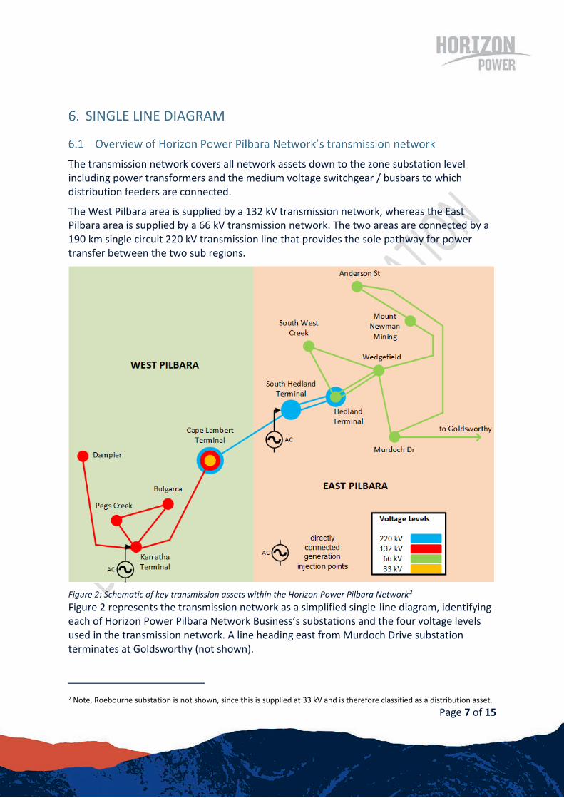
The transmission network covers all network assets down to the zone substation level including power transformers and the medium voltage switchgear / busbars to which distribution feeders are connected.
The West Pilbara area is supplied by a 132 kV transmission network, whereas the East Pilbara area is supplied by a 66 kV transmission network. The two areas are connected by a 190 km single circuit 220 kV transmission line that provides the sole pathway for power transfer between the two sub regions.
Figure 2: Schematic of key transmission assets within the Horizon Power Pilbara Network2 Figure 2 represents the transmission network as a simplified single-line diagram, identifying each of Horizon Power Pilbara Network Business’s substations and the four voltage levels used in the transmission network. A line heading east from Murdoch Drive substation terminates at Goldsworthy (not shown).
2 Note, Roebourne substation is not shown, since this is supplied at 33 kV and is therefore classified as a distribution asset.
Page 8 of 15
Figure 2 shows that there are two large generating stations (each containing multiple units) directly connected to the Horizon Power Network at Karratha and South Hedland Terminals.
Figure 2 shows the interconnections with networks owned by other parties but does not show those networks nor the large generating units connected to those networks. There are generators connected through the Alinta network that interconnect at Wedgefield and Murdoch Drive and the Rio Tinto network that interconnect at Dampier and Cape Lambert.
Transmission networks owned by Rio Tinto and Alinta parallel the Horizon Power Network. Some network element failures on either the Rio Tinto, Alinta or Horizon Power networks result in power flows on other parties’ networks. These power flows allow loads on all networks to continue to be supplied following the network failure. For this reason, the North West Interconnected System (NWIS) is considered as an interconnected system for the purpose of determining network constraints.

Page 9 of 15
SYSTEM CONSTRAINTS AND LIMIT ADVICE
Horizon Power Pilbara Network Business assesses, on a rolling basis, the ability of the transmission network to supply existing and future demand in the Horizon Power Network and support flows arising from the interconnections to other systems.
Horizon Power Pilbara Network Business will continue to work with all stakeholders, including the Pilbara ISO to improve information sharing in order to support robust modelling, network planning and operation.
The constraints and limitations detailed below have been established by applying the Horizon Power Planning Contingency Criteria to the following load and generation scenarios:
1. The existing maximum, shoulder, and minimum system loads.
2. Each possible generation output scenario that meets the requirements of the system load and the Essential System Services Requirements (ESS) determined by the ISO.
These loads have been based on Horizon Power’s 2020 demand and energy forecasts.
The limit advice (network and generation constraints developed by a Networks Service Provider for the ISO) presented below have been developed in response to the requirements in the Pilbara Network Rules but without any guidance or input from the ISO and therefore should be considered preliminary. The following relates to this preliminary advice.
• These limits have been determined based on steady state studies. There may be additional limiting factors which impact the values presented in the initial limit advice.
• These limits are a reflection of the Horizon Power Network at the time the modelling was performed. Connection of new loads or generators will inevitably impact these limits.
• The NWIS is an interconnected system consisting of three registered network service providers (NSPs). Horizon Power has sought to only present limits of its own network below, however in determining these figures information on the nature of the other networks was required (see discussion in 6.2) and this information has not yet been confirmed by the ISO.
• The Independent System Operator has yet to establish the form of the constraint rules and if any requirements exist on NSPs as to the form of their limit advice. Horizon Power has used best endeavours to present what it understands the ISO will require.

Page 10 of 15
Table 1 provides the largest overloads that result from the consideration of every feasible generation arrangement (without limit) to meet the system load adopting Horizon Power’s NWIS Planning Standards - Contingency Planning Criteria. Table 1: Summary of System Constraints
Constraint Number
Circuit Max Overload Generation Limit (Refer
Table 2) 1 AST-MDR 71 105% A 2 CLB-CBS 61 284% Rio Tinto Limit 3 HDT-WFD 71 124% A,C @ 180 4 HDT-WFD 72 124% A 5 HPS-MDR 71 138% B @ 140 6 MDR-WFD 71 188% A @ 170, B @ 180 7 SHP-HDT X2 104% A @ 200 8 TIG T Line 1 221% B 9 TIG T Line 2 115% A @ 200
10 HDT T1/T2 150% A 11 CLB T1/T2 159% C, D 12 DMP T1 153% D @ 100
Limits that have a @ have a higher limit than detailed in Table 1 for that constraint. The figure that follows the @ details the higher limit figure. These network constraints are provided graphically in Figure 3.

Page 11 of 15
Figure 3: Schematic with location and direction of current network constraints
The generation limits detailed in Table 2 resolve the system constraints detailed in Table 1 and Figure 3 . Table 2 System Generation Limits to Resolve Network Constraints (under normal operating conditions)
# Limit Limit (MVA)
A ATCO plus TransAlta West Pilbara Load Area plus 1503 MVA
B Import from Alinta 75MVA minus load at Tiger Substation
C Import from Alinta plus TransAlta East Pilbara Load Centre Plus 60MVA
D ATCO West Pilbara Load Centre Plus 60MVA4
E Net import from Rio Tinto 30
F Net export to Rio Tinto 40
3 Assumes use of distribution transfer capacity at zone substations. 4 Circulating currents caused by the interconnection with the Rio Tinto System can reduce this limit depending on the dispatch of Rio Tinto generation.

Page 12 of 15
New and modified connections to the network may require specific network investment and may change the limit advice. The requirements and impacts of each network connection change is determined through the connection application process (refer to Horizon Power’s User Access Guide).
OTHER KEY TECHNICAL CONSTRAINTS AND CAPACITIES
The maximum short circuit level at a given point in a network may be used by electricity networks and their customers to specify equipment ratings and protection schemes.
Estimated maximum short circuit levels for a range of connection points in the Horizon Power Network are shown in APPENDIX A. Please note that the values should be treated as indicative only as actual fault levels are dependent on many factors and may vary depending on specific connection requirements.
In addition, Horizon Power Pilbara Network Business has specific design requirements that apply to new connections, in relation to fault level withstand capability and protection systems.
Customers seeking to connect to, or increase supply within, the Horizon Power Network should contact Horizon Power Pilbara Network Business to discuss requirements, or to request the latest fault level information.
The Horizon Power distribution network (the electricity network operating at voltages below 66 kV) covers the medium voltage (1 kV to 33 kV) and low voltage (below 1 kV) feeder assets that reticulate supply to the vast majority of customers on the Horizon Power Network.
A summary of estimated spare capacities available to connect new loads at individual substations is provided in APPENDIX A. Spare Transformer Capacities at Substations. These values are provided as a range and should be treated as indicative as spare capacity is subject to change and may vary depending on specific connection requirements.
Customers seeking to connect to, or increase supply within, the distribution network should contact Horizon Power Pilbara Network Business to discuss their requirements.
Over the next 5 years, most customers of the Horizon Power Network are expected to be able to connect embedded renewable systems of up to 200 kW to the LV network without any form of generation management. However, Horizon Power Pilbara Network Business anticipates that customers seeking to connect systems larger than 200 kW will be required to install a feed-in management system.

Page 13 of 15
Horizon Power maintains a tool on its website, which customers can use to check whether the Horizon Power Network has sufficient hosting capacity to accommodate their proposed embedded renewable system (see https://horizonpower.com.au/solar/eligibility/). This assessment considers only the impacts of the proposed embedded renewable system on generation plant operating on the Horizon Network (whether connected directly or indirectly).
MAJOR NETWORK INVESTMENTS Significant committed or potential investments in the Horizon Power Network are listed in Table 3 below. Table 3: Committed and potential major investments in Horizon Power Pilbara Network (5-year outlook)
Project Name (status)
Description Drivers Earliest in service
Dampier: Dampier to Karratha 132 kV Line Replacement (completed)
A 19 km, 132 kV transmission line connecting the Karratha Terminal Substation to the Dampier Substation. Aging assets, old design, strategic location. Reliability of the assets have important implications for system security implications.
Asset Service (age and condition)
FY2020-21
Port Hedland: Wedgefield Substation transformer replacements (committed)
Align transformer uprating at Wedgefield for N-1 supply with end-of-life replacement need. Establish or upgrade 22kV switchgear at Wedgefield Substations.
Capacity, Reliability, Asset Service (age)
FY2021-22
Roebourne: Roebourne Substation transformer replacements (completed)
The existing Roebourne 33/11kV 5 MVA transformers have reached the end of their design life, and a recent review of the transformers indicate that their condition requires replacement to ensure reliability of supply. In addition, there are safety and maintainability issues with aging oil filled switchgear.
Asset Service (age and condition)
FY2020-21
FURTHER INFORMATION For further information, please contact Horizon Power Pilbara Network Business at Horizon Power’s Port Hedland or Karratha regional offices:
KARRATHA REGIONAL OFFICE
Lot 1966 Stovehill Road Karratha, Western Australia 6714 Phone: (08) 9159 7250 Email: [email protected]
PORT HEDLAND REGIONAL OFFICE
18 Anderson Street Port Hedland, Western Australia 6721 Phone: (08) 9173 8281 Email: [email protected]

Page 14 of 15
APPENDIX A MAXIMUM SHORT CIRCUIT LEVELS
This appendix lists maximum short circuit levels forecast at each of the Horizon Power Network major nodes. This information should only be used as an approximate guide. Appendix Table 1: Estimated maximum short circuit levels
Substation Region Voltage (kV) Fault level – three phase (kA)
Fault level - single phase (kA)
AST East Pilbara 22 6.9 9.8 BUL West Pilbara 22 8.6 8.2 CLB West Pilbara 33 15.4 21.4 DMP West Pilbara 33 7.4 9.7 MDR East Pilbara 22 5.4 7.6 PCK West Pilbara 22 8.7 9.3 ROE West Pilbara 11 8.8 10.1 SWC East Pilbara 22 7.4 8.1 WFD East Pilbara 22 10.5 11.4
Note: these estimates of maximum fault levels are based on studies carried out March 2021.
Please note that these estimates should be treated as indicative as actual fault levels are dependent on many factors and may vary depending on specific connection requirements.
In addition, Horizon Power Pilbara Network Business has specific design requirements that apply to new connections, in relation to fault level withstand capability and protection systems.

Page 15 of 15
APPENDIX B SPARE TRANSFORMER CAPACITIES AT SUBSTATIONS
This appendix provides ranges for the estimated spare capacity available at Horizon Power substations today and five years into the future.
The estimates provided in Appendix Table 2 are based on comparing the thermal ratings of substation transformers to the forecast network demand.
These estimates are based on N-1 supply reliability, unless otherwise stated. Where appropriate, these estimates are given as a range, reflecting the uncertainties as to future demand and the need to avoid disclosing commercially sensitive information in the case of substations supplying only a small number of large loads.
Please note that these estimates of substation capacity do not guarantee that this level of power can be supplied to any project seeking to connect to the relevant substation. Horizon Power Pilbara Network Business will need to undertake dedicated connection studies to accurately assess the capacity available for specific projects, taking thermal limits and other factors such as voltage limits, into account. Appendix Table 2: Estimated spare substation capacity based on thermal ratings
Substation Region Estimated spare capacity as at July
2020 (MVA)
Forecast spare capacity in 2025
(MVA)
AST East Pilbara 10 to 20 10 to 20
BUL West Pilbara 10 to 20 10 to 20
CLB West Pilbara 0 to 5 0 to 5
DMP5 West Pilbara 10 to 20 10 to 20
MDR East Pilbara 5 to 10 5 to 10
PCK West Pilbara 10 to 20 10 to 20
ROE West Pilbara 0 to 5 0 to 5
SWC East Pilbara 0 0
WFD East Pilbara 20 to 30 10 to 20
Note: these estimates of spare capacity are based on studies carried out September 2019.
Please note that these estimates should be treated as indicative as spare capacity is subject to change and may vary depending on specific connection requirements. The substation spare capacity does not necessarily indicate spare capacity in the upstream and downstream network to facilitate connection through a substation.
5 DMP has no N-1 due to being classed as a ‘minor substation’