Embed Size (px)
Citation preview


Hong Kong Section of Guangzhou-Shenzhen-Hong Kong Express Rail Link (XRL)
Commissioning Test Report for the Fixed Plant Noise at Mai Po (MPV), Ngau Tam Mei (NTV) and Shing Mun (SMV) Ventilation Buildings; ERS Plant Building – North (SPN) and ERS Plant Building – South (SPS)
MTR Corporation
July 2018

Hong Kong Section of Guangzhou-Shenzhen-Hong Kong Express Rail Link (XRL)
Commissioning Test Report for the Fixed Plant Noise at Mai Po (MPV), Ngau Tam Mei (NTV)
and Shing Mun (SMV) Ventilation Buildings; ERS Plant Building – North (SPN) and ERS Plant
Building – South (SPS)
-1-
1 Introduction
The Hong Kong Section of Guangzhou-Shenzhen-Hong Kong Express Rail Link (XRL) Project
(hereinafter known as “XRL”) covers a 26km long underground rail line on dedicated tracks
that run between the terminus in West Kowloon and the boundary at Huanggang, where
connects with the XRL Mainland section. XRL Project also includes the construction of
ventilation buildings, emergency access points, stabling sidings and maintenance facilities
and an emergency rescue siding (ERS) (formerly known as rescue emergency station).
The Environmental Impact Assessment (EIA) Report (Register No.: AEIA-143/2009) was
approved on 28 September 2009 by the Director of Environmental Protection (DEP) under
the Environmental Impact Assessment Ordinance (EIAO). Following the approval of the EIA
Report, an environmental permit (EP) was granted on 16 October 2009 (EP No: EP-349/2009)
for the construction and operation of the Project. Variations of environmental permit (VEP)
were subsequently applied and the latest Environmental Permit (EP No: EP-349/2009/M)
(hereinafter known as “the EP”) was issued by Director of Environmental Protection (DEP) on
25 June 2018.
This report is prepared with reference to EP Condition 2.36, “The Permit Holder shall, no
later than two weeks before the commencement of the operation of the Project, deposit with
the Director a Commissioning Test Report to confirm the compliance of the operational air-
borne and ground-borne noise levels in accordance with the EIA Report and the application
for variation of an environmental permit No. VEP-377/2012 and its attached documents”.
MTR Corporation has prepared the Commissioning Test Report for Fixed Plant Noise for the
noise measurement to show the compliance of noise criteria in accordance with the EIA
Report and the EP; also the noise measurement for investigation of any tonal, impulsive and
intermittent characteristics from the fixed plant noise sources. This report presents the
noise measurement methodology, calculated Sound Power Levels from noise measurements,
results of noise measurement for the fixed plant noise sources installed at Mai Po (MPV),
Ngau Tam Mei (NTV) and Shing Mun (SMV) Ventilation Buildings; ERS Plant Building – North
(SPN) and ERS Plant Building – South (SPS); and confirming any characteristics of tonality,
impulsiveness and intermittency. For the fixed plant noise verification at the other
ventilation buildings and West Kowloon Terminal (WKT) areas, separate reports would be
submitted.
2 Noise Criteria
2.1 Fixed Plant Noise Criteria in EIA
With reference to the IND-TM under the Noise Control Ordinance (NCO), the relevant
acceptable noise levels (ANL) where determined based on the area sensitivity rating (ASR).

Hong Kong Section of Guangzhou-Shenzhen-Hong Kong Express Rail Link (XRL)
Commissioning Test Report for the Fixed Plant Noise at Mai Po (MPV), Ngau Tam Mei (NTV)
and Shing Mun (SMV) Ventilation Buildings; ERS Plant Building – North (SPN) and ERS Plant
Building – South (SPS)
-2-
The fixed plant noise criteria for the representative noise sensitive receivers (NSRs) were
determined in EIA as follow (whichever is lower):
5dB(A) below the appropriate ANL set out in the IND-TM (the ANL-5dB(A) criterion);
or
The prevailing background noise levels where the prevailing background noise level
is 5dB(A) below the appropriate ANL (i.e. ANL-5dB(A))
The noise criteria above were determined for planning purpose. While for operation, the
fixed plant noise is controlled by a Noise Abatement Notices system governed by the NCO.
The fixed plant noise criteria for the NSRs along the XRL alignment in MPV, NTV, SMV, SPN
and SPS area, with the latest status of representative NSRs, are presented in Table 2.1 below.
Appropriate corrections in tonal, impulsive or intermittent characteristics should be applied,
where applicable, in accordance with IND-TM during the commissioning test.
Table 2.1 Summary of Fixed Plant Noise Criteria
NSR Description Area Sensitivity Rating (ASR) (a)
Noise Criteria, dB(A) (a)
Day and Evening Time
Night-time
Mai Po Ventilation Building (MPV) (Figure 2.1)
MP1 House 5 Phase A Royal Palms
B 60 50
MP5 Proposed Comprehensive Development at Wo Shang Wai
A 51 45
MP6 Planned village house at Village Zone
B 60 50
Ngau Tam Mei Ventilation Building (NTV) (Figure 2.2)
NT1 Yau Tam Mei Village House
A 55 44
NT1a (b) Yau Tam Mei Village House
A 55 44
NT4 Yau Tam Mei Village House
A 55 44
NT4a (b) Yau Tam Mei Village House
A 55 44
NT4b (b) Yau Tam Mei Village House
A 55 44
Shing Mun Ventilation Building (SMV) (Figure 2.3)
SM1 Sau Shan House, Cheung Shan Estate
B 60 50
SM4 Shui Hong Nursing Home
B 60 50
ERS Plant Building - North (SPN) (Figure 2.4)

Hong Kong Section of Guangzhou-Shenzhen-Hong Kong Express Rail Link (XRL)
Commissioning Test Report for the Fixed Plant Noise at Mai Po (MPV), Ngau Tam Mei (NTV)
and Shing Mun (SMV) Ventilation Buildings; ERS Plant Building – North (SPN) and ERS Plant
Building – South (SPS)
-3-
NSR Description Area Sensitivity Rating (ASR) (a)
Noise Criteria, dB(A) (a)
Day and Evening Time
Night-time
SS6 No.32 Leung Uk Tsuen B 52 45
SS7 Leung Uk Tsuen Village House
B 49 47
SS10 DD110 LOT462, Wang Toi Shan
B 49 47
SS12 265 Kam Tai Road B 49 47
SS15 Abandoned village house in Shek Kong
B 49 47
ERS Plant Building - South (SPS) (Figure 2.5)
SS2 Nam Hing Lei Village House
B 49 39
SS4 Leung Uk Tsuen Village House
B 49 40
SS5 51A Leung Uk Tsuen B 52 45
SS11a Lueng Uk Tsuen Squats
B 52 50
SS14 Planned village house at Village Zone
B 49 47
SS20 (b) Village house in Shek Kong
B 49 40
Note: (a) ASR and noise criteria either follow that defined in the EIA Report or relevant application for
variation of environmental permit (VEP-377/2012) where appropriate.
(b) These are representative NSRs additional to those identified in the EIA Report which the ASR
and noise criteria are defined in Environmental Review Report for the application for
variation of environmental permit (VEP-377-2012).
Fixed plant noise sources include: ventilation fans for building services, and plenum for
tunnel ventilation, which are generally located inside plant rooms. Noise generated from
indoor fixed plants would be emitted through louvres. The worst case scenario is when all
eligible fixed plants at the same location operating concurrently under “normal scenario” for
XRL operation during daytime and evening time periods; and night-time period, respectively.
The worst case scenario was considered for compliance check against the fixed plant noise
criteria and the noise measurement to confirm any characteristics of tonality, impulsiveness
and intermittency at the identified NSRs.
Table 2.2 below summarised the information of the fixed plant noise sources and the layout
plan is shown in Figures 2.1 to 2.5a.
Table 2.2 Summary of Fixed Plant Noise Sources
Source Location Direction Facing
Louvre ID
Mai Po Ventilation Building (MPV) (Figure 2.1)

Hong Kong Section of Guangzhou-Shenzhen-Hong Kong Express Rail Link (XRL)
Commissioning Test Report for the Fixed Plant Noise at Mai Po (MPV), Ngau Tam Mei (NTV)
and Shing Mun (SMV) Ventilation Buildings; ERS Plant Building – North (SPN) and ERS Plant
Building – South (SPS)
-4-
Source Location Direction Facing
Louvre ID
ECS duct North N1
FS control room North N2
LV switch room North N3
Tunnel ventilation shaft East E1
Tunnel ventilation shaft South S1
Tunnel ventilation shaft South S2
Tunnel ventilation shaft West W1
Air Release Louvre West W2
Ngau Tam Mei Ventilation Building (NTV) (Figure 2.2)
Tunnel ventilation shaft North N1
Tunnel ventilation shaft North N2
CTER North N3
ECS duct North N4
Tunnel ventilation shaft East E1
Tunnel ventilation shaft East E2
Tunnel ventilation shaft South S1
Tunnel ventilation shaft South S2
LV switch room South S3
LV switch room South S4
LV switch room South S5
Exhaust Air Duct South S6
UPS Room Fresh Air Intake West W1
Shing Mun Ventilation Building (SMV) (Figure 2.3)
Tunnel ventilation shaft North N1
FS inlet North N2
MCC room North N3
Exhaust air louvre North N4
Staircase pressurization fan room North N5
UPS room East E1
LV switch room East E2
Fresh air louvre East E3
Staircase pressurization fan room 1 East E4
Staircase pressurization fan room 2 East E5
Tunnel ventilation shaft South S1
Sprinkler & FS pump room South S2
Air compressor receiver room South S3
Tunnel ECS control room South S4
Staircase pressurization fan room South S5
Tunnel ventilation shaft West W1
Tunnel ventilation shaft West W2
SPS air release louvre West W3
Track section cabin room West W4
ERS Plant Building - North (SPN) (Figures 2.4 and 2.4a)
Tunnel Ventilation Shaft North N1
Tunnel Ventilation Shaft North N2

Hong Kong Section of Guangzhou-Shenzhen-Hong Kong Express Rail Link (XRL)
Commissioning Test Report for the Fixed Plant Noise at Mai Po (MPV), Ngau Tam Mei (NTV)
and Shing Mun (SMV) Ventilation Buildings; ERS Plant Building – North (SPN) and ERS Plant
Building – South (SPS)
-5-
Source Location Direction Facing
Louvre ID
Dog House North N3
Tunnel Ventilation Shaft East E1
T.ECS Control Room East E2
Dog House East E3
Tunnel Ventilation Shaft South S1
Tunnel Ventilation Shaft South S2
Tunnel Ventilation Shaft West W1
ABBCS Room West W2
ERS Plant Building - South (SPS) (Figures 2.5 and 2.5a)
Tunnel Ventilation Shaft North N1
Tunnel Ventilation Shaft North N2
Dog House North N3
Tunnel Ventilation Shaft East E1
Air Compressor Receiver Room East E2
T.ECS Control Room East E3
Dog House East E4
Dog House East E5
Tunnel Ventilation Shaft South S1
Tunnel Ventilation Shaft South S2
Dog House South S3
Tunnel Ventilation Shaft West W1
Building Service Control Room West W2
MCC Room West W3
Dog House West W4
3 Methodology
3.1 Noise Measurement for the Fixed Plants
Noise measurements to obtain the noise levels of the fixed plants were undertaken by
Supreme Acoustics Research Limited, GAS Joint Venture and ATAL Building Services
Engineering Ltd. The commissioning tests were carried out by qualified persons possessing
at least 7 years of noise control experience and a corporate member of Hong Kong Institute
of Acoustics or equivalent in accordance with S3.22 of the XRL EM&A Manual.
3.1.1 Methodology
Three measurement methods, namely Method 1 (at or near NSR), Method 2 (Far Field) and
Method 3 (Near Field), have been developed based on NCO-TM, basic acoustic principles
and ISO 3746-2010: Acoustics – Determination of sound power levels and sound energy levels
of noise sources using sound pressure – Survey method using an enveloping measurement
surface over a reflecting plane, respectively. Given the fixed plant noise sources are steady,
all proposed methods could be adopted for all types of fixed plant source depending on the
site environment/constraints that might affect the possibility to obtain valid results,
considerations including but not limited to:

Hong Kong Section of Guangzhou-Shenzhen-Hong Kong Express Rail Link (XRL)
Commissioning Test Report for the Fixed Plant Noise at Mai Po (MPV), Ngau Tam Mei (NTV)
and Shing Mun (SMV) Ventilation Buildings; ERS Plant Building – North (SPN) and ERS Plant
Building – South (SPS)
-6-
Background noise with less influence to the measured noise levels
Free of obstacles between measurement location and noise source
Accessibility and Safety Concerns
Considering the reliability of data collection, i.e. results not influenced by the above-
mentioned considerations, and the measurement efficiency on site, the selection of
methodology was prioritized based on efficient measurement as Method 1 (at or near NSR)
> Method 2 (Far Field) > Method 3 (Near Field). However, various considerations which may
affect the validity of results using Method 1 were taken in account, such as the distances
between fixed plants and NSRs at MPV and SPN/SPS are too far away (at least 66m for MPV,
120m for SPN and 159m for SPS) and some of these NSRs are screened by noise barriers (e.g.
MP1, SS4, SS11a, SS15, SS20), under Proposed Comprehensive Development at Wo Shang
Wai, Yuen Long (EP No: EP-311/2008/E) and under the Project at Shek Kong Stabling Sidings
respectively (refer to Figures 2.1, 2.4 and 2.5); where the background noise at NSRs would
mask the fixed plant noises from MPV and SPN/SPS. NSRs at NTV has no appropriate
accessible location which meets the minimum distance requirement, etc. For SMV,
considering there are heavy traffic and bus stops along Cheung Pei Shan Estate Road West
immediately in front of the NSRs; obtaining valid results using Method 1 was considered
unlikely. As such, only Method 2 and Method 3 were considered applicable. Method used
for each louvre is presented in Appendix A3. Details of the measurement methodology are
shown in Appendix A1.
Method 1 – Measuring Sound Pressure Level at NSR or Near NSR
- Measurement at NSR or near NSR at distance D away from the louvre, where D was
at least two times the largest dimension b of the louvre and rounded up to integer,
i.e.: D≧2b
- The microphone was pointing toward the louvre and three measurements were
taken when the noise source from the louvre was switched ON
- Background noise level was taken when the noise source from louvre was switched
OFF
- The sound pressure level (SPL) at NSR or near NSR was determined by the following
equation:
Background corrected Lp = Lp + BG - [20logD +8] (if applicable) + façade correction (if
applicable)
Where
Lp is the average Leq,1min of all measurements, in dB(A);
BG is the background correction factor, in dB(A);
D is separation between the center of louvre or surface of the plant and the
microphone, in metres.
Method 2 – Measuring Sound Power Level by Far Field Method for Louvres or for Plants

Hong Kong Section of Guangzhou-Shenzhen-Hong Kong Express Rail Link (XRL)
Commissioning Test Report for the Fixed Plant Noise at Mai Po (MPV), Ngau Tam Mei (NTV)
and Shing Mun (SMV) Ventilation Buildings; ERS Plant Building – North (SPN) and ERS Plant
Building – South (SPS)
-7-
- The microphone was positioned at the perpendicular distance D away from the
center of the louvre or the surface of the plant, where D was at least two times the
largest dimension b of the louvre or plant and rounded up to integer, i.e.: D≧2b
- The microphone was pointing toward the center of the louvre/combined louvre area
or the center the plant; and three measurements were taken when the noise source
from the louvre was switched ON
- Background noise level was taken when the noise source from the louvre or plant
was switched OFF
- The sound power level (SWL) of the louvre or the plant was determined, based on
basic acoustic principles, by the following equation:
Lw = Lp + 20logD,center +8 + BG
Where
Lp is the average Leq,1min of all measurements, in dB(A);
D,center is separation between the center of louvre or plant and the microphone, in
metres;
BG is the background correction factor, in dB(A).
Method 3 – Measuring Sound Power Level by Near Field Method for Louvres or for Plants
- A right parallelepiped hypothetical measurement box for each louvre or each
surface of a plant was determined according to ISO 3746:2010, with each side being
spaced a distance D from the corresponding side of the louvre or plant
- Each of the 5 planes of the measurement box was subdivided into equal-sized
rectangular grids, the length of each side of the grids should be less than or equal to
3 times of distance D, i.e. grid length ≤3D
- The microphone was pointing toward the center of each grid, and a measurement
was taken for each grid during the noise source from the louvre was switched ON
- Background noise level was taken when the noise source from louvre or plant was
switched OFF
- The SWL of the louvre or the plant was determined by the following equation:
Lw = Lp + 10log(S) - K1A - K2A
Where
Lp is the averaged measured Leq of all measurement points, in dB(A);
S is the total surface area over the measurement box (total 5 planes), in m2;
K1A is the background correction factor as described in ISO 3746:2010, in dB(A);
K2A is the environmental correction for sound absorption and reflection as described
in ISO 3746:2010, in dB(A).
Except for Method 3, which was adopted with reference to ISO 3746:2010; the noise sources
measured using Method 1 or Method 2 were considered steady if the difference between

Hong Kong Section of Guangzhou-Shenzhen-Hong Kong Express Rail Link (XRL)
Commissioning Test Report for the Fixed Plant Noise at Mai Po (MPV), Ngau Tam Mei (NTV)
and Shing Mun (SMV) Ventilation Buildings; ERS Plant Building – North (SPN) and ERS Plant
Building – South (SPS)
-8-
the maximum and minimum Leq is less than or equal to 1dB(A), ie, ≤1dB(A); average Leq
was therefore considered. Otherwise, the maximum Leq would be adopted for SWL
determination as a conservative approach.
3.1.2 Measurement Equipment
The sound level meters and calibrators used for noise measurements are listed in Table 3.1.
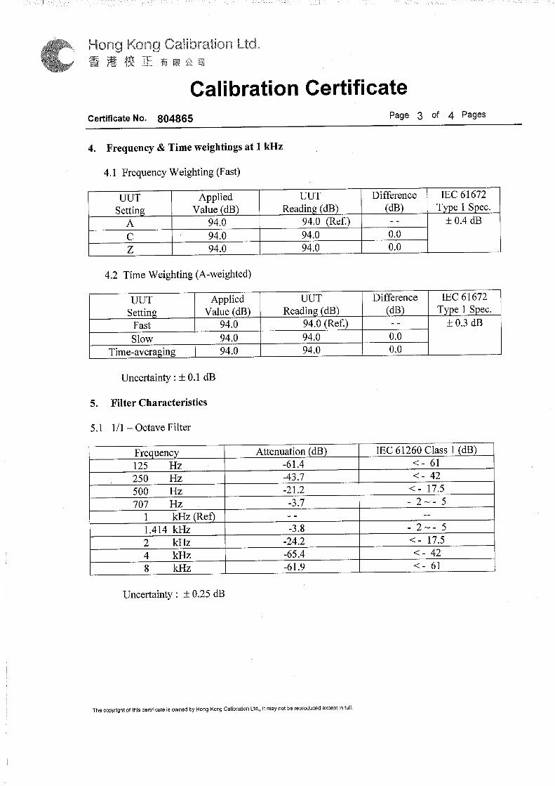
The instruments complied with International Electrotechnical Commission Publications
651:1979 (Type 1) and 804:1985 (Type 1) or equivalent international standards. Calibration
certificates are shown in Appendix A2.
Table 3.1 Noise Measurement Equipment
Equipment Model Serial Number
Sound Level Meter NTi XL2 5011
NTi XL2 5617
NTi XL2 6240
Casella CEL-63X 5044655
Calibrator BSWA TECH CA111 320248
Casella CEL-120/1 5060836
Before and after each series of measurements, a calibration check was carried out on the
sound level meter by the calibrator. The difference between the readings made before and
after each series of measurements shall be less than or equal to 1.0 dB.
3.1.3 Measurement Schedule
The noise measurements were carried out during daytime, evening time and night-time
periods, where the fixed plant items were operated steadily and continuously at their
noisiest operating mode under normal scenario. The noise measurement schedule is shown
in Table 3.2.
Table 3.2 Measurement Schedule
Location Date Time
MPV 9-10, 11-12 Oct 2017 22:00 – 06:00
13 Oct 2017 10:00 – 12:00
22 Nov 2017 00:00 – 06:00
NTV 30 Aug 2017 18:00 – 22:00
11 Oct 2017 11:00 – 16:00
12, 14 Dec 2017 14:00 – 20:00
SMV 27-28 Apr 2017 22:00 – 05: 00
15 Nov 2017 14:00 – 17:00
SPN
20–21 Apr 2017 00:00 – 03:00
1 Dec 2017 10:30 – 12:00
SPS
20–21 Apr 2017 00:00 – 03:00
1 Dec 2017 14:00 – 16:00
10 Jan 2018 16:00 – 18:00

Hong Kong Section of Guangzhou-Shenzhen-Hong Kong Express Rail Link (XRL)
Commissioning Test Report for the Fixed Plant Noise at Mai Po (MPV), Ngau Tam Mei (NTV)
and Shing Mun (SMV) Ventilation Buildings; ERS Plant Building – North (SPN) and ERS Plant
Building – South (SPS)
-9-
3.2 Noise Measurement to Confirm Any Characteristics of Tonality,
Impulsiveness and Intermittency at NSRs
3.2.1 Measurement Equipment
The sound level meters and calibrators used for noise measurements are listed in Table 3.3.
The instruments complied with International Electrotechnical Commission Publications
651:1979 (Type 1) and 804:1985 (Type 1) or equivalent international standards. Calibration
certificates are shown in Appendix A2.
Table 3.3 Noise Measurement Equipment
Equipment Model Serial Number
Sound Level Meter Casella CEL-63X 5044655
Bruel & Kjaer 2250-L 2701830
Bruel & Kjaer 2250 2704790
NTi XL2 5011
NTi XL2 5617
NTi XL2 6240
Calibrator Casella CEL-120/1 5060836
BSWA TECH CA111 320248
3.2.2 Measurement Parameters
With reference to the IND-TM, the noise measurement was conducted at the representative
NSR for LAeq (30min), in one-third octave band under the worst case scenario, ie, “normal
scenario” during daytime and evening time periods; and night-time period, respectively.
The fixed plant noise sources will be operated steadily and continuously, and therefore no
intermittency and impulsiveness are expected at the NSR. However, the characteristics of
intermittency and impulsiveness will be recorded, if any, based on observation during
measurement.
2 sets of background noise level, LAeq (5min), and in one-third octave band, were measured at
each measurement location when all fixed plant noise sources were not in operation.
3.2.3 Measurement Location
The noise measurement was carried out at the first layer of NSRs for the concerned areas.
The measurement locations are summarised in Table 3.4 and shown in Figures 2.1 to 2.5.
Table 3.4 Measurement Locations
Location NSR Description
MPV MP1 House 5 Phase A Royal Palms
MP5 Proposed Comprehensive Development at Wo Shang Wai
MP6 Planned village house at Village Zone
NTV NT1a Yau Tam Mei Village House
NT4a Yau Tam Mei Village House

Hong Kong Section of Guangzhou-Shenzhen-Hong Kong Express Rail Link (XRL)
Commissioning Test Report for the Fixed Plant Noise at Mai Po (MPV), Ngau Tam Mei (NTV)
and Shing Mun (SMV) Ventilation Buildings; ERS Plant Building – North (SPN) and ERS Plant
Building – South (SPS)
-10-
Location NSR Description
SMV SM1 Sau Shan House, Cheung Shan Estate
SM4 Shui Hong Nursing House
SPN
SS7 Leung Uk Tsuen Village House
SS10 DD110 LOT 452, Wang Toi Shan
SS15(a) Abandoned village house in Shek Kong
SPS SS11a(a) Leung Uk Tsuen Squats
SS20(a) Village house in Shek Kong Note:
(a) Certain direction of the ventilation shaft is totally or partially screened by the proposed noise
barriers at Shek Kong Stabling Sidings (SSS).
3.2.4 Measurement Schedule
The noise measurements were carried out at the monitoring location for MPV, NTV, SMV,
SPN and SPS, where the fixed plant items were operated steadily and continuously at their
noisiest operating mode under normal scenario. The noise measurement schedule is shown
in Table 3.5. Sample measurement photos of MPV, NTV, SMV, SPN and SPS are shown in
Appendix A3.
Table 3.5 Measurement Schedule
Location Date
MPV 25 – 26 Apr 2018
NTV 17 – 18 May 2018
SMV 8 – 9 Jun 2018
SPN 24 – 25 May 2018
SPS 24 – 25 May 2018
4 Measurement Results
4.1 The Noise Levels of Fixed Plant Noise Sources
The noise levels measured under the worst case scenario are determined and presented in
Table 4.1. Details of the measurement results are shown in Appendix A3.
Table 4.1 Summary of Sound Power Levels for Fixed Plants
Works Area
Direction Facing/ Elevation Calculated SWL LAeq, dB(A)
MPV North N1 (a) 67
North N2 69
North N3 72
East E1 74
South S1 74
South S2 75
West W1 70
West W2 (a) 69
NTV North N1 72

Hong Kong Section of Guangzhou-Shenzhen-Hong Kong Express Rail Link (XRL)
Commissioning Test Report for the Fixed Plant Noise at Mai Po (MPV), Ngau Tam Mei (NTV)
and Shing Mun (SMV) Ventilation Buildings; ERS Plant Building – North (SPN) and ERS Plant
Building – South (SPS)
-11-
Works Area
Direction Facing/ Elevation Calculated SWL LAeq, dB(A)
North N2 70
North N3 61
North N4 (a) 73
East E1 77
East E2 72
South S1 (a) 78
South S2 (a) 78
South S3 (a) 76
South S4 (a) 71
South S5 (a) 76
South S6 (a) 88
West W1 (a) 82
SMV
North N1 80
North N2 63
North N3 77
North N4 61
North N5 (a) 74
East E1 (a) 89
East E2 81
East E3 62
East E4 (a) 74
East E5 (a) 67
South S1 89
South S2 84
South S3 86
South S4 86
South S5 (a) 68
West W1 76
West W2 76
West W3 (a) 97
West W4 78
SPN North N1 84
North N2 84
North N3 66
East E1 85
East E2 64
East E3 68
South S1 90
South S2 89
West W1 87
West W2 72
SPS
North N1 88
North N2 90
North N3 71

Hong Kong Section of Guangzhou-Shenzhen-Hong Kong Express Rail Link (XRL)
Commissioning Test Report for the Fixed Plant Noise at Mai Po (MPV), Ngau Tam Mei (NTV)
and Shing Mun (SMV) Ventilation Buildings; ERS Plant Building – North (SPN) and ERS Plant
Building – South (SPS)
-12-
Works Area
Direction Facing/ Elevation Calculated SWL LAeq, dB(A)
East E1 84
East E2 90
East E3 89
East E4 78
East E5 76
South S1 82
South S2 84
South S3 82
West W1 84
West W2 76
West W3 80
West W4 74 Note:
(a) The plant would be operated during day and evening time only under normal scenario.
A compliance check against the fixed plant noise criteria at NSR was conducted. The
cumulative noise levels from noise sources were assessed to ensure the compliance with the
noise criterion. Table 4.2 shows the results, details of the calculation are also given in
Appendix A3.
Table 4.2 Cumulative Fixed Plant Noise at NSR
NSR Source Location
Cumulative SPL, dB(A)
Noise Criteria, dB(A)
Compliance (Y/N)
Day and Evening
Time
Night-time
Day and Evening
Time
Night-time
Day and Evening
Time
Night-time
MP1
Ventilation Shaft and Building Service
29 28 60 50 Y Y
MP5
Ventilation Shaft and Building Service
34 33 51 45 Y Y
MP6
Ventilation Shaft and Building Service
35 35 60 50 Y Y
NT1
Ventilation Shaft for N/B (a) and Building Service
42 36 55 44 Y Y
Ventilation Shaft for S/B (a) and Building Service
44 40 55 44 Y Y
NT1a
Ventilation Shaft for N/B (a) and Building Service
43 40 55 44 Y Y
Ventilation Shaft 44 42 55 44 Y Y

Hong Kong Section of Guangzhou-Shenzhen-Hong Kong Express Rail Link (XRL)
Commissioning Test Report for the Fixed Plant Noise at Mai Po (MPV), Ngau Tam Mei (NTV)
and Shing Mun (SMV) Ventilation Buildings; ERS Plant Building – North (SPN) and ERS Plant
Building – South (SPS)
-13-
NSR Source Location
Cumulative SPL, dB(A)
Noise Criteria, dB(A)
Compliance (Y/N)
Day and Evening
Time
Night-time
Day and Evening
Time
Night-time
Day and Evening
Time
Night-time
for S/B (a) and Building Service
NT4
Ventilation Shaft for N/B (a) and Building Service
44 42 55 44 Y Y
Ventilation Shaft for S/B (a) and Building Service
42 36 55 44 Y Y
NT4a
Ventilation Shaft for N/B (a) and Building Service
44 42 55 44 Y Y
Ventilation Shaft for S/B (a) and Building Service
42 37 55 44 Y Y
NT4b
Ventilation Shaft for N/B (a) and Building Service
40 36 55 44 Y Y
Ventilation Shaft for S/B (a) and Building Service
41 38 55 44 Y Y
SM1
Ventilation Shaft for N/B (a) and Building Service
56 49 60 50 Y Y
Ventilation Shaft for S/B (a) and Building Service
56 49 60 50 Y Y
SM4
Ventilation Shaft for N/B (a) and Building Service
59 47 60 50 Y Y
Ventilation Shaft for S/B (a) and Building Service
59 45 60 50 Y Y
SS6
Ventilation Shaft for N/B (a) and Building Service
39 39 52 45 Y Y
Ventilation Shaft for S/B (a) and Building Service
41 41 52 45 Y Y
SS7
Ventilation Shaft for N/B (a) and Building Service
39 39 49 47 Y Y
Ventilation Shaft for S/B (a) and
41 41 49 47 Y Y

Hong Kong Section of Guangzhou-Shenzhen-Hong Kong Express Rail Link (XRL)
Commissioning Test Report for the Fixed Plant Noise at Mai Po (MPV), Ngau Tam Mei (NTV)
and Shing Mun (SMV) Ventilation Buildings; ERS Plant Building – North (SPN) and ERS Plant
Building – South (SPS)
-14-
NSR Source Location
Cumulative SPL, dB(A)
Noise Criteria, dB(A)
Compliance (Y/N)
Day and Evening
Time
Night-time
Day and Evening
Time
Night-time
Day and Evening
Time
Night-time
Building Service
SS10
Ventilation Shaft for N/B (a) and Building Service
36 36 49 47 Y Y
Ventilation Shaft for S/B (a) and Building Service
35 35 49 47 Y Y
SS12
Ventilation Shaft for N/B (a) and Building Service
36 36 49 47 Y Y
Ventilation Shaft for S/B (a) and Building Service
33 33 49 47 Y Y
SS15(b)
Ventilation Shaft for N/B (a) and Building Service
39 39 49 47 Y Y
Ventilation Shaft for S/B (a) and Building Service
42 42 49 47 Y Y
SS2
Ventilation Shaft for N/B (a) and Building Service
32 32 49 39 Y Y
Ventilation Shaft for S/B (a) and Building Service
31 31 49 39 Y Y
SS4(b)
Ventilation Shaft for N/B (a) and Building Service
35 35 49 40 Y Y
Ventilation Shaft for S/B (a) and Building Service
35 35 49 40 Y Y
SS5
Ventilation Shaft for N/B (a) and Building Service
43 43 52 45 Y Y
Ventilation Shaft for S/B (a) and Building Service
43 43 52 45 Y Y
SS11a(b)
Ventilation Shaft for N/B (a) and Building Service
42 42 52 50 Y Y
Ventilation Shaft for S/B (a) and Building Service
40 40 52 50 Y Y

Hong Kong Section of Guangzhou-Shenzhen-Hong Kong Express Rail Link (XRL)
Commissioning Test Report for the Fixed Plant Noise at Mai Po (MPV), Ngau Tam Mei (NTV)
and Shing Mun (SMV) Ventilation Buildings; ERS Plant Building – North (SPN) and ERS Plant
Building – South (SPS)
-15-
NSR Source Location
Cumulative SPL, dB(A)
Noise Criteria, dB(A)
Compliance (Y/N)
Day and Evening
Time
Night-time
Day and Evening
Time
Night-time
Day and Evening
Time
Night-time
SS14
Ventilation Shaft for N/B (a) and Building Service
40 40 49 47 Y Y
Ventilation Shaft for S/B (a) and Building Service
40 40 49 47 Y Y
SS20(b)
Ventilation Shaft for N/B (a) and Building Service
36 36 49 40 Y Y
Ventilation Shaft for S/B (a) and Building Service
36 36 49 40 Y Y
Note: (a) Tunnel ventilation would only be operated for either northbound (N/B) or southbound (S/B)
direction under normal scenario for NTV, SMV, SPN and SPS. Tunnel ventilation would be
operated for both northbound (N/B) and southbound (S/B) direction under normal scenario
for MPV.
(b) Certain direction of the ventilation shaft is totally or partially screened by the proposed noise
barriers at SSS.
4.2 The Characteristics of Tonality, Impulsiveness and Intermittency at NSRs
Noise measurement to confirm any characteristics of tonality, impulsiveness and
intermittency at the identified NSRs were conducted under the normal scenarios during
daytime and evening, and during night-time, respectively and summarised in Table 4.3
below. In each scenario, two sets of noise measurements, LAeq(30min), in one-third octave
band, were carried out to confirm that the difference in the measured noise levels with and
without operation of fixed plant noise sources were less than 3.0 dB(A). That means the
fixed plant noise sources from the ventilation buildings and the plant buildings are not
considered as significant noise sources at the NSR. Noise measurements at NTV and some
NSRs at SPN/SPS (e.g. SS11a, SS15 and SS20) were dominated by community noise; MPV,
SMV and some NSRs at SPN/SPS (e.g. SS7, SS10) were dominated by the road traffic noise
along Castle Peak Road – Mai Po and San Tin Highway, Cheung Pei Shan Estate Road West
and Kam Tin Road, respectively; characteristics of tonality, impulsiveness and intermittency
due to the fixed plant noise sources from the ventilation buildings was not noticeable during
the measurement. Detailed results of noise measurements are shown in Appendix A4.

Hong Kong Section of Guangzhou-Shenzhen-Hong Kong Express Rail Link (XRL)
Commissioning Test Report for the Fixed Plant Noise at Mai Po (MPV), Ngau Tam Mei (NTV)
and Shing Mun (SMV) Ventilation Buildings; ERS Plant Building – North (SPN) and ERS Plant
Building – South (SPS)
-16-
Table 4.3 Noise measurement Results at NSR
NSR Scenario
Measured Noise Level LAeq(30min),
dB(A), (measurement time)
(b)
Averaged Background Level
LAeq(5min), dB(A), (measurement time)
(a)
Difference between Measured Noise
Level and Background Level, dB(A), (< 3.0 or >=
3.0)
MP1
Day and Evening
Time
49.0 (22:45 – 23:15) 48.4 (00:25 – 00:55)
48.9 (22:00 – 22:20) < 3.0
Night-time
49.0 (01:00 – 01:30) 49.7 (01:30 – 02:00)
49.6 (02:10 – 02:20) < 3.0
MP5
Day and Evening
Time
48.1 (22:45 – 23:15) 48.9 (00:25 – 00:55)
46.7 (22:00 – 22:20) < 3.0
Night-time
49.8 (01:00 – 01:30) 48.4 (01:30 – 02:00)
47.8 (02:05 – 02:20) < 3.0
MP6
Day and Evening
Time
48.7 (22:45 – 23:15) 46.4 (00:25 – 00:55)
48.5 (22:00 – 22:20) < 3.0
Night-time
48.4 (01:00 – 01:30) 47.6 (01:30 – 02:00)
47.1 (02:05 – 02:15) < 3.0
NT1a
Day and Evening
Time
52.0 (23:25 – 23:55) 52.8 (23:56 – 00:26)
52.2 (23:08 – 23:18) < 3.0
Night-time
46.9 (00:28 – 00:58) 45.7 (01:03 – 01:33)
44.0 (01:54 – 02:14) < 3.0
NT4a
Day and Evening
Time
50.8 (23:24 – 23:54) 52.5 (23:55 – 00:25)
52.1 (23:13 – 23:23) < 3.0
Night-time
52.8 (00:32 – 01:02) 53.2 (01:03 – 01:33)
52.6 (01:40 – 01:50) < 3.0
SM1
Day and Evening
Time
64.2 (22:39 – 23:09) 64.3 (23:10 – 23:40)
65.1 (22:12 – 22:27) < 3.0
Night-time
61.3 (23:42 – 00:12) 60.9 (00:13 – 00:43)
59.7 (00:49 – 00:59) < 3.0
SM4
Day and Evening
Time
60.6 (22:30 – 23:00) 59.4 (23:00 – 23:30)
60.4 (21:45 – 21:55) < 3.0
Night-time
56.6 (23:34 – 00:04) 56.7 (00:04 – 00:34)
55.6 (00:39 – 00:49) < 3.0
SS7
Day and Evening
Time
50.7 (23:43 – 00:13) 48.5 (00:13 – 00:43)
50.2 (23:30 – 23:40) < 3.0
Night-time
47.9 (00:50 – 01:20) 47.2 (01:20 – 01:50)
46.9 (02:25 – 02:40) < 3.0
SS10 Day and 58.9 (23:42 – 00:12) 57.2 (23:18 – 23:28) < 3.0

Hong Kong Section of Guangzhou-Shenzhen-Hong Kong Express Rail Link (XRL)
Commissioning Test Report for the Fixed Plant Noise at Mai Po (MPV), Ngau Tam Mei (NTV)
and Shing Mun (SMV) Ventilation Buildings; ERS Plant Building – North (SPN) and ERS Plant
Building – South (SPS)
-17-
NSR Scenario
Measured Noise Level LAeq(30min),
dB(A), (measurement time)
(b)
Averaged Background Level
LAeq(5min), dB(A), (measurement time)
(a)
Difference between Measured Noise
Level and Background Level, dB(A), (< 3.0 or >=
3.0)
Evening Time
56.8 (00:12 – 00:42)
Night-time
55.5 (00:46 – 01:16) 55.8 (01:16 – 01:46)
54.4 (02:24 – 02:34) < 3.0
SS15
Day and Evening
Time
47.7 (23:43 – 00:13) 47.6 (00:13 – 00:43)
49.0 (22:33 – 22:43) < 3.0
Night-time
48.4 (00:50 – 01:20) 48.4 (01:20 – 01:50)
48.8 (02:25 – 02:35) < 3.0
SS11a
Day and Evening
Time
48.3 (23:52 – 00:22) 48.3 (00:22 – 00:52)
46.9 (23:15 – 23:33) < 3.0
Night-time
47.6 (00:55 – 01:25) 45.5 (01:25 – 01:55)
46.7 (02:43 – 02:53) < 3.0
SS20
Day and Evening
Time
57.1 (23:42 – 00:12) 57.3 (00:14 – 00:44)
57.5 (23:04 – 23:15) < 3.0
Night-time
57.1 (00:46 – 01:16) 57.1 (01:17 – 01:47)
57.5 (02:24 – 02:35) < 3.0
Note: (a) The noise levels at NSRs were dominated either by community noise or road traffic noise; the
fixed plants from the ventilation buildings and the plant buildings were not considered as
significant noise sources at the NSR.
(b) The scenarios were arranged for the purpose of testing and commissioning only. The
scenario under “day and evening time” would not happen after 2300 during the operation
phase.
As the differences between measured noise levels and background levels are all less than 3.0
dB(A), it was unable to obtain reliable corrected noise levels at the NSRs and corrections for
tonality, impulsiveness or intermittency were therefore not applicable.
5 Conclusions To fulfil the XRL EP condition 2.36, the fixed plant noise verification were undertaken and
the measurement results indicated all the fixed plant noise levels in MPV, NTV, SMV, SPN
and SPS are in compliance with the fixed plant noise criteria.

Figure 2.1 – Representative Noise Sensitive Receiver (NSR), Noise Measurement Location and Fixed Plant Sources at MPV
Key
Louvre
Representative Noise Sensitive Receiver
Measurement Location
E1
W1
S1N2
N1S2
MP6
MP1
MP5
W2
0m 22.5m
N3
10m high noise barrier (by others)

Figure 2.2 – Representative Noise Sensitive Receiver (NSR), Noise Measurement Location and Fixed Plant Sources at NTV
Key
Louvre
Representative Noise Sensitive Receiver
Measurement Location
E2
E1
N3
N2
N4
S1
NT4b NT4a NT4
NT1a NT1
S4
S3
S6
30m
E1
0m
E1
S2
N1
S5
W1
N1a
N4a

Figure 2.3 – Site layout, Noise Sensitive Receiver (NSR) and Fixed Plant Sources at SMV
W1
N2S1
W2
N1
N3
S3
S4
W4
S2
N4
E3
E4E5
E2E1SM1
SM4 Key
Louvre
Representative Noise Sensitive Receiver
Measurement Location
S5 N5
W3
0m
E1
20m
E1

Figure 2.4 – Representative Noise Sensitive Receiver (NSR), Noise Measurement Location and Fixed Plant Sources at SPN
SPN
0m 30m
SS7
SS15
SS10
Key
Louvre
Representative Noise Sensitive Receiver
Measurement Location

Figure 2.4a – Representative Noise Sensitive Receiver (NSR), Noise Measurement Location and Fixed Plant Sources at SPN
Key
Louvre
Representative Noise Sensitive Receiver
Measurement Location
W1 W2
E2 E1
E3
N2
N1
N3
S1
S2
0m 30m

Figure 2.5 – Representative Noise Sensitive Receiver (NSR), Noise Measurement Location and Fixed Plant Sources at SPS
Key
Louvre
Representative Noise Sensitive Receiver
Measurement Location
SPS
40m 0m
SS20
SS11a

Figure 2.5a – Representative Noise Sensitive Receiver (NSR), Noise Measurement Location and Fixed Plant Sources at SPS
Key
Louvre
Representative Noise Sensitive Receiver
Measurement Location
W2
E2 E1
E1
E3
N1
E1
N3
E1
S3
E1 S1
E1
S2
E1 W1
N2
E1 W3
E4
W4 E5
0m 40m

Appendix A1 –Measurement Methodology

03/07/2018 Page 1MTR Corporation
BY : MTR XRL Env Team
XRL Fixed Plant Noise Test Plan

Page 2MTR Corporation
Summary of Testing Methodology
Method Standard No of repeated measurement
No of measurement point
Measurement distance, D
To Verify
Method 1(NSR Method)
NCO - TM 3 sets of Leq1min
Depend on number of NSRs nearby
At the most affected NSR or near NSR
ANL-5 or Background Prevailing
Method 2 (Far Field Method)
Basic Acoustic Principle
3 sets of Leq1min
1 (for louvre/plant with uniform plane source)
D ≧≧≧≧2b and roundup to integer
ANL-5 or Background Prevailing
Method 3 (Near Field Method)
Developed based on ISO3746:2010
1 set of Leq 10s (a)
/1minDepend on the size of the louvre/plant and the measurement distance should follow guideline in ISO3746
At least 1m from the louvre opening/plant (unless otherwise specified)
ANL-5 or Background Prevailing
Note :(a) If fixed plant items are operated at their noisiest operating modes and are steady during measurement, 10-second will be adopted for the duration of measurement.

Page 3MTR Corporation
Method 1 – Sound Pressure Level at NSR or Near NSR for louvre or Plant
• Based on NCO - TM• The locations of measurement points are
depended on the site situation• 3.0 dB façade correction should be considered
if the location of measurement point is not at assessment point as defined in NCO-TM
• “D” must be greater than 2b and roundup to integer
• Detail calculation of the SPL should refer to the NCO-TM.
• Background noise level (BGL) should be taken for determination of background correction (BG)
• If the difference between the BGL and measured noise level (MNL) is less than 3.0 dB, BG should be capped to 3.0 dB
NSR
Plant Building
louvre
Background corrected SPL = Mean LAeq1min + BG - [20log (D) +8] (if applicable) + façade correction (if applicable)
Near NSR
Mic
“b” is the long side of the louvre “D” is the separation between louvre and microphone
if the difference between the maximum and minimum Leq >1dB(A); maximum Leq would be adopted as a conservative approach

Page 4MTR Corporation
Method 2 – Far Field Sound Power Testing Method for louvre“a” is the short side of the louvre “b” is the long side of the louvre “D” is the separation between louvre and microphone
• Based on basic acoustic principle• “D” must be greater than 2b and
roundup to integer, i.e.: D≧2b• The microphone must point to the
center of the louvre.• At least 3 sets of LAeq, 1min should be
obtained • Background noise level (BGL) should be
taken for determination of background correction (BG)
• If the difference between the BGL and measured noise level (MNL) is less than 3.0 dB, BG should be capped to 3.0 dB
SWL (Sound Power Level) = Mean measured LAeq1min + 20 log (D, center) + 8 +BG
if the difference between the maximum and minimum Leq >1dB(A); maximum Leq would be adopted as a conservative approach

Page 5MTR Corporation
Method 2 – Far Field Sound Power Testing Method for Plant
“L” is the longest side of the plant item“D, Center” is the separation between center of the plant item and microphone“D, Surface” is the separation between surface of the plant item and microphone
• “D, Surface” must be greater than twice of L (2L) and roundup to integer
• The microphone must be pointing to the center of the plant
• At least 3 sets of LAeq, 1min should be obtained at each measurement point.
• Background noise level (BGL) should be taken for determination of background correction (BG)
• If the difference between the BGL and measured noise level (MNL) is less than 3.0 dB, BG should be capped to 3.0 dB
SWL (Sound Power Level) = Mean measured LAeq1min + 20 log (D, center) + 8 + BG
if the difference between the maximum and minimum Leq >1dB(A); maximum Leq would be adopted as a conservative approach

Page 6MTR Corporation
Method 3 – Near Field Sound Power Testing Method for louvre
• Based on the principle of ISO3746 – 2010• First step is to determine a hypothetical measurement surface
/box with not less than 1m separation from the louvre.• Second, determine the location of measurement point in
accordance with the latest edition of ISO3746.• Background noise level (BGL) should be taken at each
measurement point for determination of background correction (K1A)
• At least 1 set of Leq, 10s/1min should be obtained at each measurement point
• Extra localized microphone positions on the measurement surface in the region of high noise radiation would be considered following relevant procedures in ISO 3744
• If the difference between the BGL and measured noise level (MNL) is less than 3.0 dB, K1A should be capped to 3.0 dB
• The measurement distance would be reduced if necessary to obtain higher MNL for valid measurement results
• Details calculation of the SWL should refer to the latest edition of ISO3746.
SWL = Mean LAeq over all measurement points + 10 log (total surface area over the measurement box) - K1A - K2A (sound absorption and reflection correction)
louvre
Noise Emission Direction
Measurement Point
Measurement Box
K1A refers to background noise correction factorK2A refers to environmental correction for sound absorption and reflection

Page 7MTR Corporation
Method 3 – Near Field Sound Power Testing Method for Plant
• Based on ISO 3746• The locations of measurement points are
depended on the size of the plant, which cannot be easily generalised (See figure on the left for example).
• Extra localized microphone positions on the measurement surface in the region of high noise radiation would be considered following relevant procedures in ISO 3744
• If the difference between the BGL and measured noise level (MNL) is less than 3.0 dB, K1A should be capped to 3.0 dB
• The measurement distance would be reduced if necessary to obtain higher MNL for valid measurement results
• Detail calculation of the SWL should refer to the latest edition of ISO 3746.
SWL = Mean LAeq over all measurement points + 10 log (total surface area over the measurement box) - K1A - K2A (sound absorption and reflection correction)
K1A refers to background noise correction factorK2A refers to environmental correction for sound absorption and reflection

Page 8MTR Corporation
End

Appendix A2 – Calibration Certificates


The following instrument has been tested and calibrated to the manufacturer specifications.
The calibration is traceable in accordance with ISO/IEC 17025 covering all instrument functions.
Device Type: M2230 Measurement Microphone
consisting of
MA220 Serial Number: 6240
Capsule Serial Number: 9498
Certificate Issued:
Certificate Number: 42745-6240-M2230
Results: PASSED
(for detailed report see next page)
Tested by: M.Frick
Signature:
Stamp:
Manufacturer Calibration Certificate
10 January 2017
NTi Audio AG • Im alten Riet 102 • 9494 Schaan • Liechtenstein • Europe • Tel: +423 239 6060
www.nti-audio.com • HR-Nr: 2.012.557 • MwStNr: 54306 • Bank: VP Bank, Vaduz, Acc No: 322.235.015 1/2

Date:
Calibration of: M2230 Measurement Microphone
MA220 Serial Number: 6240
Capsule Serial Number: 9498
Detailed Calibration Test Results:
Frequency response: Class 1 acc. IEC 61672
Sensitivity @ 1 kHz, 114 dBSPL 43.3 mV/Pa
Test Conditions: Temperature: 27.2 °C
Relative Humidity: 39.5 %
Air Pressure: 95.94 kPa
Calibration Equipment Used:
- Norsonic Sound Calibrator, Type 1251, S/No. 30930
Last Calibration: 05.12.2016, Next Calibration: 05.12.2018
Calibrated by Metas, Switzerland
- NTi Audio FX100, S/No. 11094
Last Calibration: 16.08.2016, Next Calibration: 16.08.2017
Calibrated by NTi Audio meeting product specifications
- MTG MV203, S/No. 0630 / Mic Capsule, MK221 S./No. 16502
Last Calibration: 30.11.2015, Next Calibration: 30.11.2017
Calibrated by MTG, Germany
1 The reported expanded uncertainty is based on a standard uncertainty multiplied by a coverage factor k=2, providing a
level of confidence of approximately 95%. The uncertainty evaluation has been carried out in accordance with the
regulations of the GUM.
calibration
uncertainty1 actual
±2.85%
10 January 2017
±0.5 °C
±2%
±0.25 kPa
-6
-4
-2
0
2
4
6
10 100 1000 10000
Se
nsitiv
ity r
ela
tive
[d
B]
Frequency [Hz]
NTi Audio AG • Im alten Riet 102 • 9494 Schaan • Liechtenstein • Europe • Tel: +423 239 6060
www.nti-audio.com • HR-Nr: 2.012.557 • MwStNr: 54306 • Bank: VP Bank, Vaduz, Acc No: 322.235.015 2/2

The following instrument has been tested and calibrated to the manufacturer specifications.
The calibration is traceable in accordance with ISO/IEC 17025 covering all instrument functions.
Device Type: M2230 Measurement Microphone
consisting of
MA220 Serial Number: 5011
Capsule Serial Number: 7698
Certificate Issued:
Certificate Number: 42818-5011-M2230
Results: PASSED
(for detailed report see next page)
Tested by: M.Frick
Signature:
Stamp:
Manufacturer Calibration Certificate
24 March 2017
NTi Audio AG • Im alten Riet 102 • 9494 Schaan • Liechtenstein • Europe • Tel: +423 239 6060
www.nti-audio.com • HR-Nr: 2.012.557 • MwStNr: 54306 • Bank: VP Bank, Vaduz, Acc No: 322.235.015 1/2

Date:
Calibration of: M2230 Measurement Microphone
MA220 Serial Number: 5011
Capsule Serial Number: 7698
Detailed Calibration Test Results:
Frequency response: Class 1 acc. IEC 61672
Sensitivity @ 1 kHz, 114 dBSPL 46.5 mV/Pa
Test Conditions: Temperature: 21.1 °C
Relative Humidity: 47.2 %
Air Pressure: 97.4 kPa
Calibration Equipment Used:
- Norsonic Sound Calibrator, Type 1251, S/No. 30930
Last Calibration: 05.12.2016, Next Calibration: 05.12.2018
Calibrated by Metas, Switzerland
- NTi Audio FX100, S/No. 11094
Last Calibration: 16.08.2016, Next Calibration: 16.08.2017
Calibrated by NTi Audio meeting product specifications
- MTG MV203, S/No. 0630 / Mic Capsule, MK221 S./No. 16502
Last Calibration: 30.11.2015, Next Calibration: 30.11.2017
Calibrated by MTG, Germany
1 The reported expanded uncertainty is based on a standard uncertainty multiplied by a coverage factor k=2, providing a
level of confidence of approximately 95%. The uncertainty evaluation has been carried out in accordance with the
regulations of the GUM.
calibration
uncertainty1 actual
±2.85%
24 March 2017
±0.5 °C
±2%
±0.25 kPa
-6
-4
-2
0
2
4
6
10 100 1000 10000
Se
nsitiv
ity r
ela
tive
[d
B]
Frequency [Hz]
NTi Audio AG • Im alten Riet 102 • 9494 Schaan • Liechtenstein • Europe • Tel: +423 239 6060
www.nti-audio.com • HR-Nr: 2.012.557 • MwStNr: 54306 • Bank: VP Bank, Vaduz, Acc No: 322.235.015 2/2

The following instrument has been tested and calibrated to the manufacturer specifications.
The calibration is traceable in accordance with ISO/IEC 17025 covering all instrument functions.
Device Type: M2230 Measurement Microphone
consisting of
MA220 Serial Number: 5617
Capsule Serial Number: 8507
Certificate Issued:
Certificate Number: 42818-5617-M2230
Results: PASSED
(for detailed report see next page)
Tested by: M.Frick
Signature:
Stamp:
Manufacturer Calibration Certificate
24 March 2017
NTi Audio AG • Im alten Riet 102 • 9494 Schaan • Liechtenstein • Europe • Tel: +423 239 6060
www.nti-audio.com • HR-Nr: 2.012.557 • MwStNr: 54306 • Bank: VP Bank, Vaduz, Acc No: 322.235.015 1/2

Date:
Calibration of: M2230 Measurement Microphone
MA220 Serial Number: 5617
Capsule Serial Number: 8507
Detailed Calibration Test Results:
Frequency response: Class 1 acc. IEC 61672
Sensitivity @ 1 kHz, 114 dBSPL 48.1 mV/Pa
Test Conditions: Temperature: 24.6 °C
Relative Humidity: 43.6 %
Air Pressure: 97.65 kPa
Calibration Equipment Used:
- Norsonic Sound Calibrator, Type 1251, S/No. 30930
Last Calibration: 05.12.2016, Next Calibration: 05.12.2018
Calibrated by Metas, Switzerland
- NTi Audio FX100, S/No. 11094
Last Calibration: 16.08.2016, Next Calibration: 16.08.2017
Calibrated by NTi Audio meeting product specifications
- MTG MV203, S/No. 0630 / Mic Capsule, MK221 S./No. 16502
Last Calibration: 30.11.2015, Next Calibration: 30.11.2017
Calibrated by MTG, Germany
1 The reported expanded uncertainty is based on a standard uncertainty multiplied by a coverage factor k=2, providing a
level of confidence of approximately 95%. The uncertainty evaluation has been carried out in accordance with the
regulations of the GUM.
calibration
uncertainty1 actual
±2.85%
24 March 2017
±0.5 °C
±2%
±0.25 kPa
-6
-4
-2
0
2
4
6
10 100 1000 10000
Se
nsitiv
ity r
ela
tive
[d
B]
Frequency [Hz]
NTi Audio AG • Im alten Riet 102 • 9494 Schaan • Liechtenstein • Europe • Tel: +423 239 6060
www.nti-audio.com • HR-Nr: 2.012.557 • MwStNr: 54306 • Bank: VP Bank, Vaduz, Acc No: 322.235.015 2/2


Appendix A3 – Fixed Plant Noise Summary

Measurement Photos
MPV
NTV
SMV
SPN
SPS

Day and Evening Time Fixed Plant Noise at NSR
Width Height
ECS duct N1 L Y 1.20 1.00 2 3 n/a 49.9 42.4 7.5 49 67 141 5 14
FS control room N2 L Y 0.80 0.80 2 2 n/a 54.8 44.4 10.4 54.8 69 150 5 15
LV switch room N3 L Y 7.00 3.00 3 1 73.0 54.9 49.9 5 53.2 72 150 5 18
Tunnel ventilation
shaftE1 L Y 12.68 5.93 3 1 161.5 54.4 51.1 3.3 51.7 74 136 10 16
Tunnel ventilation
shaftS1 L Y 8.28 5.93 3 1 117.8 55.1 49.7 5.4 53.6 74 130 5 22
Tunnel ventilation
shaftS2 L Y 9.48 5.93 3 1 129.7 54.8 46.9 7.9 54 75 121 5 23
Tunnel ventilation
shaftW1 L Y 13.00 5.93 3 1 164.7 50.2 46.3 3.9 47.9 70 123 0 23
Air Release Louvre W2 L Y 1.20 0.60 3 1 19.9 57.6 52.8 4.8 55.9 69 123 0 22
ECS duct N1 L Y 1.20 1.00 2 3 n/a 49.9 42.4 7.5 49 67 101 10 12
FS control room N2 L Y 0.80 0.80 2 2 n/a 54.8 44.4 10.4 54.8 69 116 10 13
LV switch room N3 L Y 7.00 3.00 3 1 73.0 54.9 49.9 5 53.2 72 150 5 18
Tunnel ventilation
shaftE1 L Y 12.68 5.93 3 1 161.5 54.4 51.1 3.3 51.7 74 125 10 17
Tunnel ventilation
shaftS1 L Y 8.28 5.93 3 1 117.8 55.1 49.7 5.4 53.6 74 119 0 27
Tunnel ventilation
shaftS2 L Y 9.48 5.93 3 1 129.7 54.8 46.9 7.9 54 75 97 0 30
Tunnel ventilation
shaftW1 L Y 13.00 5.93 3 1 164.7 50.2 46.3 3.9 47.9 70 88 0 26
Air Release Louvre W2 L Y 1.20 0.60 3 1 19.9 57.6 52.8 4.8 55.9 69 97 0 24
ECS duct N1 L Y 1.20 1.00 2 3 n/a 49.9 42.4 7.5 49 67 88 0 23
FS control room N2 L Y 0.80 0.80 2 2 n/a 54.8 44.4 10.4 54.8 69 73 0 27
LV switch room N3 L Y 7.00 3.00 3 1 73.0 54.9 49.9 5 53.2 72 150 5 18
Tunnel ventilation
shaftE1 L Y 12.68 5.93 3 1 161.5 54.4 51.1 3.3 51.7 74 68 0 32
Tunnel ventilation
shaftS1 L Y 8.28 5.93 3 1 117.8 55.1 49.7 5.4 53.6 74 75 5 26
Tunnel ventilation
shaftS2 L Y 9.48 5.93 3 1 129.7 54.8 46.9 7.9 54 75 95 5 25
Tunnel ventilation
shaftW1 L Y 13.00 5.93 3 1 164.7 50.2 46.3 3.9 47.9 70 99 10 15
Air Release Louvre W2 L Y 1.20 0.60 3 1 19.9 57.6 52.8 4.8 55.9 69 86 10 15
Remarks:
(i) Tunnel ventilation would be operated for both northbound (N/B) and southbound (S/B) direction under normal scenario.
(ii) Method 2 Far field method for Louvres or Plants
Method 3 Near field method for Louvres or Plants
(iii) Results are averaged from the measured noise levels.
(iv) If the difference between the background and the measured noise level is less than 3.0 dB, background noise correction factor should be capped to 3.0 dB.
(v) The calculation of SWL is in accordance with the methodology described in Section 3.1.1 and Appendix A1 of the Report. For Method 3, K2A was not claimed in the calculation.
0
MP6
Planned
village
house at
Village
Zone
Ventilation
Shaft and
Building
Service
35 60 0
MP5
Proposed
Compreh
ensive
Develop
ment at
Wo
Shang
Wai
Ventilation
Shaft and
Building
Service
34 51
Measure-
ment
Distance,
D M (m)
Surface Area
of
Measurement
Box, S (m2)
Measured
LAeq [dB(A)] (iii)
Average
Background
LAeq [dB(A)]
Louvre Size (m)
MP1
NSRNoise
Source
Method (ii)
Ventilation
Shaft and
Building
Service
House 5
Phase A
Royal
Palms
DescriptionLouvre
ID
In
operation?
(Y/N)
Plant or
Louvre?
(P/L)
29 60 0
Day and
Evening Time
Criteria
[dB(A)]
Exceedance
[dB(A)]
Corrected SPL
at NSR
[dB(A)]
Cumulative
SPL at NSR
[dB(A)]
Difference
LAeq
[dB(A)]
Background
Corrected
Measured
LAeq,mea
[dB(A)] (iv)
Calculated
SWL LAeq
[dB(A)] (v)
Distance from
Noise Source
to NSR, D N
[m]
Correction
for line of
sight, LoS
[dB(A)]

Night Time Fixed Plant Noise at NSR
Width Height
ECS duct N1 L N (ii) 1.20 1.00 2 3 n/a 49.9 42.4 7.5 49 67 141 - -
FS control room N2 L Y 0.80 0.80 2 2 n/a 54.8 44.4 10.4 54.8 69 150 5 15
LV switch room N3 L Y 7.00 3.00 3 1 73.0 54.9 49.9 5 53.2 72 150 5 18
Tunnel ventilation
shaftE1 L Y 12.68 5.93 3 1 161.5 54.4 51.1 3.3 51.7 74 136 10 16
Tunnel ventilation
shaftS1 L Y 8.28 5.93 3 1 117.8 55.1 49.7 5.4 53.6 74 130 5 22
Tunnel ventilation
shaftS2 L Y 9.48 5.93 3 1 129.7 54.8 46.9 7.9 54 75 121 5 23
Tunnel ventilation
shaftW1 L Y 13.00 5.93 3 1 164.7 50.2 46.3 3.9 47.9 70 123 0 23
Air Release Louvre W2 L N (ii) 1.20 0.60 3 1 19.9 57.6 52.8 4.8 55.9 69 123 - -
ECS duct N1 L N (ii) 1.20 1.00 2 3 n/a 49.9 42.4 7.5 49 67 101 - -
FS control room N2 L Y 0.80 0.80 2 2 n/a 54.8 44.4 10.4 54.8 69 116 10 13
LV switch room N3 L Y 7.00 3.00 3 1 73.0 54.9 49.9 5 53.2 72 150 5 18
Tunnel ventilation
shaftE1 L Y 12.68 5.93 3 1 161.5 54.4 51.1 3.3 51.7 74 125 10 17
Tunnel ventilation
shaftS1 L Y 8.28 5.93 3 1 117.8 55.1 49.7 5.4 53.6 74 119 0 27
Tunnel ventilation
shaftS2 L Y 9.48 5.93 3 1 129.7 54.8 46.9 7.9 54 75 97 0 30
Tunnel ventilation
shaftW1 L Y 13.00 5.93 3 1 164.7 50.2 46.3 3.9 47.9 70 88 0 26
Air Release Louvre W2 L N (ii) 1.20 0.60 3 1 19.9 57.6 52.8 4.8 55.9 69 97 - -
ECS duct N1 L N (ii) 1.20 1.00 2 3 n/a 49.9 42.4 7.5 49 67 88 - -
FS control room N2 L Y 0.80 0.80 2 2 n/a 54.8 44.4 10.4 54.8 69 73 0 27
LV switch room N3 L Y 7.00 3.00 3 1 73.0 54.9 49.9 5 53.2 72 150 5 18
Tunnel ventilation
shaftE1 L Y 12.68 5.93 3 1 161.5 54.4 51.1 3.3 51.7 74 68 0 32
Tunnel ventilation
shaftS1 L Y 8.28 5.93 3 1 117.8 55.1 49.7 5.4 53.6 74 75 5 26
Tunnel ventilation
shaftS2 L Y 9.48 5.93 3 1 129.7 54.8 46.9 7.9 54 75 95 5 25
Tunnel ventilation
shaftW1 L Y 13.00 5.93 3 1 164.7 50.2 46.3 3.9 47.9 70 99 10 15
Air Release Louvre W2 L N (ii) 1.20 0.60 3 1 19.9 57.6 52.8 4.8 55.9 69 86 - -
Remarks:
(i) Not used
(ii) The plant would be operated during day and evening time only under normal scenario.
(iii) Method 2 Far field method for Louvres or Plants
Method 3 Near field method for Louvres or Plants
(iv) Results are averaged from the measured noise levels.
(v) If the difference between the background and the measured noise level is less than 3.0 dB, background noise correction factor should be capped to 3.0 dB.
(vi) The calculation of SWL is in accordance with the methodology described in Section 3.1.1 and Appendix A1 of the Report. For Method 3, K2A was not claimed in the calculation.
Night-Time
Criteria
[dB(A)]
Exceedance
[dB(A)]
MP1
0
MP5
Proposed
Compreh
ensive
Develop
ment at
Wo
Shang
Wai
Ventilation
Shaft and
Building
Service
33 45 0
MP6
Planned
village
house at
Village
Zone
Ventilation
Shaft and
Building
Service
35 50
House 5
Phase A
Royal
Palms
Ventilation
Shaft and
Building
Service
28 50 0
Cumulative
SPL at NSR
[dB(A)]
Method (iii)
Measure-
ment
Distance,
D M (m)
Surface Area
of
Measurement
Box, S (m2)
Measured
LAeq [dB(A)] (iv)
Average
Background
LAeq [dB(A)]
Difference
LAeq
[dB(A)]
Background
Corrected
Measured
LAeq,mea
[dB(A)] (v)
Calculated
SWL LAeq
[dB(A)] (vi)
Distance from
Noise Source
to NSR, D N
[m]
Correction
for line of
sight, LoS
[dB(A)]
Corrected
SPL at NSR
[dB(A)]
Louvre Size (m)
Plant or
Louvre?
(P/L)
NSRNoise
SourceDescription
Louvre
ID
In
operation?
(Y/N)

Day and Evening Time Fixed Plant Noise at NSR
Width Height
Tunnel ventilation
shaftN1 L N
(i) 3.88 9.00 3 2 185.9 51 46.6 4.4 49 72 30 - -
Tunnel ventilation
shaftN2 L N
(i) 12.50 2.20 3 2 193.1 49.6 46.6 3 46.6 69 30 - -
CTER N3 L Y 0.80 1.60 3 0.5 9.1 54.2 53.2 1 51.2 61 43 0 23
ECS duct N4 L Y 2.60 2.20 3 1 36.9 58.5 53.2 5.3 57 73 45 0 35
Tunnel ventilation
shaftE1 L Y 5.08 9.00 3 2 206.3 54.1 45.9 8.2 53.4 77 45 5 34
Tunnel ventilation
shaftE2 L N
(i) 5.08 9.00 3 2 206.3 51.5 48.5 3 48.5 72 33 - -
Tunnel ventilation
shaftS1 L Y 12.51 2.20 3 2 193.2 55.5 44.6 10.9 55.5 78 50 10 29
Tunnel ventilation
shaftS2 L Y 3.88 9.00 3 2 185.9 55.9 46.9 9 55.3 78 50 10 29
LV switch room S3 L Y 3.30 2.20 3 1 41.3 54.6 39.4 15.2 54.6 71 67 10 19
LV switch room S4 L Y 2.10 3.80 3 1 43.6 54.6 39.4 15.2 54.6 71 62 10 20
LV switch room S5 L Y 1.20 3.80 3 1 36.6 60.2 39.4 20.8 60.2 76 62 10 25
Exhaust Air Duct S6 L Y 2.40 0.73 2 5 n/a 66.2 44.9 21.3 66.2 88 50 10 39
UPS Room Fresh Air
IntakeW1 L Y 3.00 2.00 2 6 n/a 59.3 51.8 7.5 58.4 82 62 10 31
Tunnel ventilation
shaftN1 L N
(i) 3.88 9.00 3 2 185.9 51 46.6 4.4 49 72 29 - -
Tunnel ventilation
shaftN2 L N
(i) 12.50 2.20 3 2 193.1 49.6 46.6 3 46.6 69 29 - -
CTER N3 L Y 0.80 1.60 3 0.5 9.1 54.2 53.2 1 51.2 61 45 0 23
ECS duct N4 L Y 2.60 2.20 3 1 36.9 58.5 53.2 5.3 57 73 48 0 34
Tunnel ventilation
shaftE1 L Y 5.08 9.00 3 2 206.3 54.1 45.9 8.2 53.4 77 43 0 39
Tunnel ventilation
shaftE2 L N
(i) 5.08 9.00 3 2 206.3 51.5 48.5 3 48.5 72 32 - -
Tunnel ventilation
shaftS1 L Y 12.51 2.20 3 2 193.2 55.5 44.6 10.9 55.5 78 49 10 29
Tunnel ventilation
shaftS2 L Y 3.88 9.00 3 2 185.9 55.9 46.9 9 55.3 78 49 10 29
LV switch room S3 L Y 3.30 2.20 3 1 41.3 54.6 39.4 15.2 54.6 71 70 10 19
LV switch room S4 L Y 2.10 3.80 3 1 43.6 54.6 39.4 15.2 54.6 71 63 10 20
LV switch room S5 L Y 1.20 3.80 3 1 36.6 60.2 39.4 20.8 60.2 76 63 10 25
Exhaust Air Duct S6 L Y 2.40 0.73 2 5 n/a 66.2 44.9 21.3 66.2 88 50 10 39
UPS Room Fresh Air
IntakeW1 L Y 3.00 2.00 2 6 n/a 59.3 51.8 7.5 58.4 82 65 10 31
Tunnel ventilation
shaftN1 L N
(i) 3.88 9.00 3 2 185.9 51 46.6 4.4 49 72 44 - -
Tunnel ventilation
shaftN2 L N
(i) 12.50 2.20 3 2 193.1 49.6 46.6 3 46.6 69 50 - -
CTER N3 L Y 0.80 1.60 3 0.5 9.1 54.2 53.2 1 51.2 61 80 5 13
ECS duct N4 L Y 2.60 2.20 3 1 36.9 58.5 53.2 5.3 57 73 86 5 24
Tunnel ventilation
shaftE1 L Y 5.08 9.00 3 2 206.3 54.1 45.9 8.2 53.4 77 40 0 40
Tunnel ventilation
shaftE2 L N
(i) 5.08 9.00 3 2 206.3 51.5 48.5 3 48.5 72 40 - -
Tunnel ventilation
shaftS1 L Y 12.51 2.20 3 2 193.2 55.5 44.6 10.9 55.5 78 50 5 34
Tunnel ventilation
shaftS2 L Y 3.88 9.00 3 2 185.9 55.9 46.9 9 55.3 78 43 5 35
LV switch room S3 L Y 3.30 2.20 3 1 41.3 54.6 39.4 15.2 54.6 71 92 5 22
In
operation?
(Y/N)
NSRNoise
SourceDescription
Louvre
ID
Plant or
Louvre?
(P/L)
Method (ii)
Measure-
ment
Distance,
D M (m)
Surface Area
of
Measurement
Box, S (m2)
Measured
LAeq [dB(A)] (iv)
Average
Background
LAeq [dB(A)]
Cumulative
SPL at NSR
[dB(A)]
Day and
Evening Time
Criteria
[dB(A)]
Exceedance
[dB(A)]
NT1
Yau Tam
Mei
Village
House
Ventilation
Shaft for
N/B (i)
and
Building
Service
42 55 0
Difference
LAeq
[dB(A)]
Background
Corrected
Measured
LAeq,mea
[dB(A)] (v)
Calculated
SWL LAeq
[dB(A)] (vi)
Distance from
Noise Source
to NSR, D N
[m]
Correction
for line of
sight, LoS
[dB(A)]
Louvre Size (m)
Ventilation
Shaft for
N/B (i)
and
Building
Service
43 55 0.0
NT4
Yau Tam
Mei
Village
House
Ventilation
Shaft for
N/B (i)
and
Building
Service
44 55
Corrected
SPL at NSR
[dB(A)]
0
NT1a
Yau Tam
Mei
Village
House

Width Height
In
operation?
(Y/N)
NSRNoise
SourceDescription
Louvre
ID
Plant or
Louvre?
(P/L)
Method (ii)
Measure-
ment
Distance,
D M (m)
Surface Area
of
Measurement
Box, S (m2)
Measured
LAeq [dB(A)] (iv)
Average
Background
LAeq [dB(A)]
Cumulative
SPL at NSR
[dB(A)]
Day and
Evening Time
Criteria
[dB(A)]
Exceedance
[dB(A)]
Difference
LAeq
[dB(A)]
Background
Corrected
Measured
LAeq,mea
[dB(A)] (v)
Calculated
SWL LAeq
[dB(A)] (vi)
Distance from
Noise Source
to NSR, D N
[m]
Correction
for line of
sight, LoS
[dB(A)]
Louvre Size (m)
Corrected
SPL at NSR
[dB(A)]
LV switch room S4 L Y 2.10 3.80 3 1 43.6 54.6 39.4 15.2 54.6 71 85 5 22
LV switch room S5 L Y 1.20 3.80 3 1 36.6 60.2 39.4 20.8 60.2 76 85 5 27
Exhaust Air Duct S6 L Y 2.40 0.73 2 5 n/a 66.2 44.9 21.3 66.2 88 80 5 40
UPS Room Fresh Air
IntakeW1 L Y 3.00 2.00 2 6 n/a 59.3 51.8 7.5 58.4 82 97 10 27
Tunnel ventilation
shaftN1 L N
(i) 3.88 9.00 3 2 185.9 51 46.6 4.4 49 72 42 - -
Tunnel ventilation
shaftN2 L N
(i) 12.50 2.20 3 2 193.1 49.6 46.6 3 46.6 69 50 - -
CTER N3 L Y 0.80 1.60 3 0.5 9.1 54.2 53.2 1 51.2 61 80 5 13
ECS duct N4 L Y 2.60 2.20 3 1 36.9 58.5 53.2 5.3 57 73 85 5 24
Tunnel ventilation
shaftE1 L Y 5.08 9.00 3 2 206.3 54.1 45.9 8.2 53.4 77 39 0 40
Tunnel ventilation
shaftE2 L N
(i) 5.08 9.00 3 2 206.3 51.5 48.5 3 48.5 72 39 - -
Tunnel ventilation
shaftS1 L Y 12.51 2.20 3 2 193.2 55.5 44.6 10.9 55.5 78 50 5 34
Tunnel ventilation
shaftS2 L Y 3.88 9.00 3 2 185.9 55.9 46.9 9 55.3 78 43 5 35
LV switch room S3 L Y 3.30 2.20 3 1 41.3 54.6 39.4 15.2 54.6 71 92 5 22
LV switch room S4 L Y 2.10 3.80 3 1 43.6 54.6 39.4 15.2 54.6 71 85 5 22
LV switch room S5 L Y 1.20 3.80 3 1 36.6 60.2 39.4 20.8 60.2 76 85 5 27
Exhaust Air Duct S6 L Y 2.40 0.73 2 5 n/a 66.2 44.9 21.3 66.2 88 80 5 40
UPS Room Fresh Air
IntakeW1 L Y 3.00 2.00 2 6 n/a 59.3 51.8 7.5 58.4 82 96 10 27
Tunnel ventilation
shaftN1 L N
(i) 3.88 9.00 3 2 185.9 51 46.6 4.4 49 72 36 - -
Tunnel ventilation
shaftN2 L N
(i) 12.50 2.20 3 2 193.1 49.6 46.6 3 46.6 69 43 - -
CTER N3 L Y 0.80 1.60 3 0.5 9.1 54.2 53.2 1 51.2 61 70 0 19
ECS duct N4 L Y 2.60 2.20 3 1 36.9 58.5 53.2 5.3 57 73 75 0 30
Tunnel ventilation
shaftE1 L Y 5.08 9.00 3 2 206.3 54.1 45.9 8.2 53.4 77 44 5 34
Tunnel ventilation
shaftE2 L N
(i) 5.08 9.00 3 2 206.3 51.5 48.5 3 48.5 72 35 - -
Tunnel ventilation
shaftS1 L Y 12.51 2.20 3 2 193.2 55.5 44.6 10.9 55.5 78 55 10 28
Tunnel ventilation
shaftS2 L Y 3.88 9.00 3 2 185.9 55.9 46.9 9 55.3 78 50 10 29
LV switch room S3 L Y 3.30 2.20 3 1 41.3 54.6 39.4 15.2 54.6 71 90 10 17
LV switch room S4 L Y 2.10 3.80 3 1 43.6 54.6 39.4 15.2 54.6 71 81 10 18
LV switch room S5 L Y 1.20 3.80 3 1 36.6 60.2 39.4 20.8 60.2 76 81 10 23
Exhaust Air Duct S6 L Y 2.40 0.73 2 5 n/a 66.2 44.9 21.3 66.2 88 70 10 36
UPS Room Fresh Air
IntakeW1 L Y 3.00 2.00 2 6 n/a 59.3 51.8 7.5 58.4 82 90 10 28
Remarks:
(i) Tunnel ventilation would only be operated for either northbound (N/B) or southbound (S/B) direction under normal scenario.
(ii) Method 2 Far field method for Louvres or Plants
Method 3 Near field method for Louvres or Plants
(iii) Results are averaged from the measured noise levels.
(iv) If the difference between the background and the measured noise level is less than 3.0 dB, background noise correction factor should be capped to 3.0 dB.
(v) The calculation of SWL is in accordance with the methodology described in Section 3.1.1 and Appendix A1 of the Report. For Method 3, K2A was not claimed in the calculation.
0
NT4a
Yau Tam
Mei
Village
House
Ventilation
Shaft for
N/B (i)
and
Building
Service
44 55 0
NT4b
Yau Tam
Mei
Village
House
Ventilation
Shaft for
N/B (i)
and
Building
Service
40 55

Day and Evening Time Fixed Plant Noise at NSR
Width Height
Tunnel ventilation
shaftN1 L Y 3.88 9.00 3 2 185.9 51 46.6 4.4 49 72 30 0 37
Tunnel ventilation
shaftN2 L Y 12.50 2.20 3 2 193.1 49.6 46.6 3 46.6 69 30 0 34
CTER N3 L Y 0.80 1.60 3 0.5 9.1 54.2 53.2 1 51.2 61 43 0 23
ECS duct N4 L Y 2.60 2.20 3 1 36.9 58.5 53.2 5.3 57 73 45 0 35
Tunnel ventilation
shaftE1 L N
(i) 5.08 9.00 3 2 206.3 54.1 45.9 8.2 53.4 77 45 - -
Tunnel ventilation
shaftE2 L Y 5.08 9.00 3 2 206.3 51.5 48.5 3 48.5 72 33 5 32
Tunnel ventilation
shaftS1 L N
(i) 12.51 2.20 3 2 193.2 55.5 44.6 10.9 55.5 78 50 - -
Tunnel ventilation
shaftS2 L N
(i) 3.88 9.00 3 2 185.9 55.9 46.9 9 55.3 78 50 - -
LV switch room S3 L Y 3.30 2.20 3 1 41.3 54.6 39.4 15.2 54.6 71 67 10 19
LV switch room S4 L Y 2.10 3.80 3 1 43.6 54.6 39.4 15.2 54.6 71 62 10 20
LV switch room S5 L Y 1.20 3.80 3 1 36.6 60.2 39.4 20.8 60.2 76 62 10 25
Exhaust Air Duct S6 L Y 2.40 0.73 2 5 n/a 66.2 44.9 21.3 66.2 88 50 10 39
UPS Room Fresh Air
IntakeW1 L Y 3.00 2.00 2 6 n/a 59.3 51.8 7.5 58.4 82 62 10 31
Tunnel ventilation
shaftN1 L Y 3.88 9.00 3 2 185.9 51 46.6 4.4 49 72 29 0 38
Tunnel ventilation
shaftN2 L Y 12.50 2.20 3 2 193.1 49.6 46.6 3 46.6 69 29 0 35
CTER N3 L Y 0.80 1.60 3 0.5 9.1 54.2 53.2 1 51.2 61 45 0 23
ECS duct N4 L Y 2.60 2.20 3 1 36.9 58.5 53.2 5.3 57 73 48 0 34
Tunnel ventilation
shaftE1 L N
(i) 5.08 9.00 3 2 206.3 54.1 45.9 8.2 53.4 77 43 - -
Tunnel ventilation
shaftE2 L Y 5.08 9.00 3 2 206.3 51.5 48.5 3 48.5 72 32 0 37
Tunnel ventilation
shaftS1 L N
(i) 12.51 2.20 3 2 193.2 55.5 44.6 10.9 55.5 78 49 - -
Tunnel ventilation
shaftS2 L N
(i) 3.88 9.00 3 2 185.9 55.9 46.9 9 55.3 78 49 - -
LV switch room S3 L Y 3.30 2.20 3 1 41.3 54.6 39.4 15.2 54.6 71 70 10 19
LV switch room S4 L Y 2.10 3.80 3 1 43.6 54.6 39.4 15.2 54.6 71 63 10 20
LV switch room S5 L Y 1.20 3.80 3 1 36.6 60.2 39.4 20.8 60.2 76 63 10 25
Exhaust Air Duct S6 L Y 2.40 0.73 2 5 n/a 66.2 44.9 21.3 66.2 88 50 10 39
UPS Room Fresh Air
IntakeW1 L Y 3.00 2.00 2 6 n/a 59.3 51.8 7.5 58.4 82 65 10 31
Tunnel ventilation
shaftN1 L Y 3.88 9.00 3 2 185.9 51 46.6 4.4 49 72 44 5 29
Tunnel ventilation
shaftN2 L Y 12.50 2.20 3 2 193.1 49.6 46.6 3 46.6 69 50 5 25
CTER N3 L Y 0.80 1.60 3 0.5 9.1 54.2 53.2 1 51.2 61 80 5 13
ECS duct N4 L Y 2.60 2.20 3 1 36.9 58.5 53.2 5.3 57 73 86 5 24
Tunnel ventilation
shaftE1 L N
(i) 5.08 9.00 3 2 206.3 54.1 45.9 8.2 53.4 77 40 - -
Tunnel ventilation
shaftE2 L Y 5.08 9.00 3 2 206.3 51.5 48.5 3 48.5 72 40 0 35
Tunnel ventilation
shaftS1 L N
(i) 12.51 2.20 3 2 193.2 55.5 44.6 10.9 55.5 78 50 - -
Tunnel ventilation
shaftS2 L N
(i) 3.88 9.00 3 2 185.9 55.9 46.9 9 55.3 78 43 - -
LV switch room S3 L Y 3.30 2.20 3 1 41.3 54.6 39.4 15.2 54.6 71 92 5 22
In
operation?
(Y/N)
NSRNoise
SourceDescription
Louvre
ID
Plant or
Louvre?
(P/L)
Method (ii)
Measure-
ment
Distance,
D M (m)
Surface Area
of
Measurement
Box, S (m2)
Measured
LAeq [dB(A)] (iv)
Average
Background
LAeq [dB(A)]
Cumulative
SPL at NSR
[dB(A)]
Day and
Evening Time
Criteria
[dB(A)]
Exceedance
[dB(A)]
NT1
Yau Tam
Mei
Village
House
Ventilation
Shaft for
S/B (i)
and
Building
Service
43 55 0
Difference
LAeq
[dB(A)]
Background
Corrected
Measured
LAeq,mea
[dB(A)] (v)
Calculated
SWL LAeq
[dB(A)] (vi)
Distance from
Noise Source
to NSR, D N
[m]
Correction
for line of
sight, LoS
[dB(A)]
Louvre Size (m)
Ventilation
Shaft for
S/B (i)
and
Building
Service
44 55 0.0
NT4
Yau Tam
Mei
Village
House
Ventilation
Shaft for
S/B (i)
and
Building
Service
42 55
Corrected
SPL at NSR
[dB(A)]
0
NT1a
Yau Tam
Mei
Village
House

Width Height
In
operation?
(Y/N)
NSRNoise
SourceDescription
Louvre
ID
Plant or
Louvre?
(P/L)
Method (ii)
Measure-
ment
Distance,
D M (m)
Surface Area
of
Measurement
Box, S (m2)
Measured
LAeq [dB(A)] (iv)
Average
Background
LAeq [dB(A)]
Cumulative
SPL at NSR
[dB(A)]
Day and
Evening Time
Criteria
[dB(A)]
Exceedance
[dB(A)]
Difference
LAeq
[dB(A)]
Background
Corrected
Measured
LAeq,mea
[dB(A)] (v)
Calculated
SWL LAeq
[dB(A)] (vi)
Distance from
Noise Source
to NSR, D N
[m]
Correction
for line of
sight, LoS
[dB(A)]
Louvre Size (m)
Corrected
SPL at NSR
[dB(A)]
LV switch room S4 L Y 2.10 3.80 3 1 43.6 54.6 39.4 15.2 54.6 71 85 5 22
LV switch room S5 L Y 1.20 3.80 3 1 36.6 60.2 39.4 20.8 60.2 76 85 5 27
Exhaust Air Duct S6 L Y 2.40 0.73 2 5 n/a 66.2 44.9 21.3 66.2 88 80 5 40
UPS Room Fresh Air
IntakeW1 L Y 3.00 2.00 2 6 n/a 59.3 51.8 7.5 58.4 82 97 10 27
Tunnel ventilation
shaftN1 L Y 3.88 9.00 3 2 185.9 51 46.6 4.4 49 72 42 5 30
Tunnel ventilation
shaftN2 L Y 12.50 2.20 3 2 193.1 49.6 46.6 3 46.6 69 50 5 25
CTER N3 L Y 0.80 1.60 3 0.5 9.1 54.2 53.2 1 51.2 61 80 5 13
ECS duct N4 L Y 2.60 2.20 3 1 36.9 58.5 53.2 5.3 57 73 85 5 24
Tunnel ventilation
shaftE1 L N
(i) 5.08 9.00 3 2 206.3 54.1 45.9 8.2 53.4 77 39 - -
Tunnel ventilation
shaftE2 L Y 5.08 9.00 3 2 206.3 51.5 48.5 3 48.5 72 39 0 35
Tunnel ventilation
shaftS1 L N
(i) 12.51 2.20 3 2 193.2 55.5 44.6 10.9 55.5 78 50 - -
Tunnel ventilation
shaftS2 L N
(i) 3.88 9.00 3 2 185.9 55.9 46.9 9 55.3 78 43 - -
LV switch room S3 L Y 3.30 2.20 3 1 41.3 54.6 39.4 15.2 54.6 71 92 5 22
LV switch room S4 L Y 2.10 3.80 3 1 43.6 54.6 39.4 15.2 54.6 71 85 5 22
LV switch room S5 L Y 1.20 3.80 3 1 36.6 60.2 39.4 20.8 60.2 76 85 5 27
Exhaust Air Duct S6 L Y 2.40 0.73 2 5 n/a 66.2 44.9 21.3 66.2 88 80 5 40
UPS Room Fresh Air
IntakeW1 L Y 3.00 2.00 2 6 n/a 59.3 51.8 7.5 58.4 82 96 10 27
Tunnel ventilation
shaftN1 L Y 3.88 9.00 3 2 185.9 51 46.6 4.4 49 72 36 0 36
Tunnel ventilation
shaftN2 L Y 12.50 2.20 3 2 193.1 49.6 46.6 3 46.6 69 43 0 31
CTER N3 L Y 0.80 1.60 3 0.5 9.1 54.2 53.2 1 51.2 61 70 0 19
ECS duct N4 L Y 2.60 2.20 3 1 36.9 58.5 53.2 5.3 57 73 75 0 30
Tunnel ventilation
shaftE1 L N
(i) 5.08 9.00 3 2 206.3 54.1 45.9 8.2 53.4 77 44 - -
Tunnel ventilation
shaftE2 L Y 5.08 9.00 3 2 206.3 51.5 48.5 3 48.5 72 35 5 31
Tunnel ventilation
shaftS1 L N
(i) 12.51 2.20 3 2 193.2 55.5 44.6 10.9 55.5 78 55 - -
Tunnel ventilation
shaftS2 L N
(i) 3.88 9.00 3 2 185.9 55.9 46.9 9 55.3 78 50 - -
LV switch room S3 L Y 3.30 2.20 3 1 41.3 54.6 39.4 15.2 54.6 71 90 10 17
LV switch room S4 L Y 2.10 3.80 3 1 43.6 54.6 39.4 15.2 54.6 71 81 10 18
LV switch room S5 L Y 1.20 3.80 3 1 36.6 60.2 39.4 20.8 60.2 76 81 10 23
Exhaust Air Duct S6 L Y 2.40 0.73 2 5 n/a 66.2 44.9 21.3 66.2 88 70 10 36
UPS Room Fresh Air
IntakeW1 L Y 3.00 2.00 2 6 n/a 59.3 51.8 7.5 58.4 82 90 10 28
Remarks:
(i) Tunnel ventilation would only be operated for either northbound (N/B) or southbound (S/B) direction under normal scenario.
(ii) Method 2 Far field method for Louvres or Plants
Method 3 Near field method for Louvres or Plants
(iii) Results are averaged from the measured noise levels.
(iv) If the difference between the background and the measured noise level is less than 3.0 dB, background noise correction factor should be capped to 3.0 dB.
(v) The calculation of SWL is in accordance with the methodology described in Section 3.1.1 and Appendix A1 of the Report. For Method 3, K2A was not claimed in the calculation.
0
NT4a
Yau Tam
Mei
Village
House
Ventilation
Shaft for
S/B (i)
and
Building
Service
42 55 0
NT4b
Yau Tam
Mei
Village
House
Ventilation
Shaft for
S/B (i)
and
Building
Service
41 55

Night Time Fixed Plant Noise at NSR
Width Height
Tunnel ventilation
shaftN1 L N
(i) 3.88 9.00 3 2 185.9 51 46.6 4.4 49 72 30 - -
Tunnel ventilation
shaftN2 L N
(i) 12.50 2.20 3 2 193.1 49.6 46.6 3 46.6 69 30 - -
CTER N3 L Y 0.80 1.60 3 0.5 9.1 54.2 53.2 1 51.2 61 43 0 23
ECS duct N4 L N (ii) 2.60 2.20 3 1 36.9 58.5 53.2 5.3 57 73 45 - -
Tunnel ventilation
shaftE1 L Y 5.08 9.00 3 2 206.3 54.1 45.9 8.2 53.4 77 45 5 34
Tunnel ventilation
shaftE2 L N
(i) 5.08 9.00 3 2 206.3 51.5 48.5 3 48.5 72 33 - -
Tunnel ventilation
shaftS1 L Y 12.51 2.20 3 2 193.2 55.5 44.6 10.9 55.5 78 50 10 29
Tunnel ventilation
shaftS2 L Y 3.88 9.00 3 2 185.9 55.9 46.9 9 55.3 78 50 10 29
LV switch room S3 L N (ii) 3.30 2.20 3 1 41.3 54.6 39.4 15.2 54.6 71 67 - -
LV switch room S4 L N (ii) 2.10 3.80 3 1 43.6 54.6 39.4 15.2 54.6 71 62 - -
LV switch room S5 L N (ii) 1.20 3.80 3 1 36.6 60.2 39.4 20.8 60.2 76 62 - -
Exhaust Air Duct S6 L N (ii) 2.40 0.73 2 5 n/a 66.2 44.9 21.3 66.2 88 50 - -
UPS Room Fresh Air
IntakeW1 L N
(ii) 3.00 2.00 2 6 n/a 59.3 51.8 7.5 58.4 82 62 - -
Tunnel ventilation
shaftN1 L N
(i) 3.88 9.00 3 2 185.9 51 46.6 4.4 49 72 29 - -
Tunnel ventilation
shaftN2 L N
(i) 12.50 2.20 3 2 193.1 49.6 46.6 3 46.6 69 29 - -
CTER N3 L Y 0.80 1.60 3 0.5 9.1 54.2 53.2 1 51.2 61 45 0 23
ECS duct N4 L N (ii) 2.60 2.20 3 1 36.9 58.5 53.2 5.3 57 73 48 - -
Tunnel ventilation
shaftE1 L Y 5.08 9.00 3 2 206.3 54.1 45.9 8.2 53.4 77 43 0 39
Tunnel ventilation
shaftE2 L N
(i) 5.08 9.00 3 2 206.3 51.5 48.5 3 48.5 72 32 - -
Tunnel ventilation
shaftS1 L Y 12.51 2.20 3 2 193.2 55.5 44.6 10.9 55.5 78 49 10 29
Tunnel ventilation
shaftS2 L Y 3.88 9.00 3 2 185.9 55.9 46.9 9 55.3 78 49 10 29
LV switch room S3 L N (ii) 3.30 2.20 3 1 41.3 54.6 39.4 15.2 54.6 71 70 - -
LV switch room S4 L N (ii) 2.10 3.80 3 1 43.6 54.6 39.4 15.2 54.6 71 63 - -
LV switch room S5 L N (ii) 1.20 3.80 3 1 36.6 60.2 39.4 20.8 60.2 76 63 - -
Exhaust Air Duct S6 L N (ii) 2.40 0.73 2 5 n/a 66.2 44.9 21.3 66.2 88 50 - -
UPS Room Fresh Air
IntakeW1 L N
(ii) 3.00 2.00 2 6 n/a 59.3 51.8 7.5 58.4 82 65 - -
Tunnel ventilation
shaftN1 L N
(i) 3.88 9.00 3 2 185.9 51 46.6 4.4 49 72 44 - -
Tunnel ventilation
shaftN2 L N
(i) 12.50 2.20 3 2 193.1 49.6 46.6 3 46.6 69 50 - -
CTER N3 L Y 0.80 1.60 3 0.5 9.1 54.2 53.2 1 51.2 61 80 5 13
ECS duct N4 L N (ii) 2.60 2.20 3 1 36.9 58.5 53.2 5.3 57 73 86 - -
Tunnel ventilation
shaftE1 L Y 5.08 9.00 3 2 206.3 54.1 45.9 8.2 53.4 77 40 0 40
Tunnel ventilation
shaftE2 L N
(i) 5.08 9.00 3 2 206.3 51.5 48.5 3 48.5 72 40 - -
Tunnel ventilation
shaftS1 L Y 12.51 2.20 3 2 193.2 55.5 44.6 10.9 55.5 78 50 5 34
Tunnel ventilation
shaftS2 L Y 3.88 9.00 3 2 185.9 55.9 46.9 9 55.3 78 43 5 35
LV switch room S3 L N (ii) 3.30 2.20 3 1 41.3 54.6 39.4 15.2 54.6 71 92 - -
LV switch room S4 L N (ii) 2.10 3.80 3 1 43.6 54.6 39.4 15.2 54.6 71 85 - -
0
NT1a
Yau Tam
Mei
Village
House
Ventilation
Shaft for
N/B (i)
and
Building
Service
40 44 0.0
NT4
Yau Tam
Mei
Village
House
Ventilation
Shaft for
N/B (i)
and
Building
Service
42 44
Cumulative
SPL at NSR
[dB(A)]
Night-Time
Criteria
[dB(A)]
Exceedance
[dB(A)]
NT1
Yau Tam
Mei
Village
House
Ventilation
Shaft for
N/B (i)
and
Building
Service
36 44 0
Difference
LAeq [dB(A)]
Background
Corrected
Measured
LAeq,mea
[dB(A)] (v)
Calculated
SWL LAeq
[dB(A)] (vi)
Distance from
Noise Source
to NSR, D N
[m]
Correction
for line of
sight, LoS
[dB(A)]
Louvre Size (m)
Corrected
SPL at NSR
[dB(A)]
In
operation?
(Y/N)
NSRNoise
SourceDescription
Louvre
ID
Plant or
Louvre?
(P/L)
Method (iii)
Measure-
ment
Distance,
D M (m)
Surface Area of
Measurement
Box, S (m2)
Measured
LAeq [dB(A)] (iv)
Average
Background
LAeq [dB(A)]

Width Height
Cumulative
SPL at NSR
[dB(A)]
Night-Time
Criteria
[dB(A)]
Exceedance
[dB(A)]
Difference
LAeq [dB(A)]
Background
Corrected
Measured
LAeq,mea
[dB(A)] (v)
Calculated
SWL LAeq
[dB(A)] (vi)
Distance from
Noise Source
to NSR, D N
[m]
Correction
for line of
sight, LoS
[dB(A)]
Louvre Size (m)
Corrected
SPL at NSR
[dB(A)]
In
operation?
(Y/N)
NSRNoise
SourceDescription
Louvre
ID
Plant or
Louvre?
(P/L)
Method (iii)
Measure-
ment
Distance,
D M (m)
Surface Area of
Measurement
Box, S (m2)
Measured
LAeq [dB(A)] (iv)
Average
Background
LAeq [dB(A)]
LV switch room S5 L N (ii) 1.20 3.80 3 1 36.6 60.2 39.4 20.8 60.2 76 85 - -
Exhaust Air Duct S6 L N (ii) 2.40 0.73 2 5 n/a 66.2 44.9 21.3 66.2 88 80 - -
UPS Room Fresh Air
IntakeW1 L N
(ii) 3.00 2.00 2 6 n/a 59.3 51.8 7.5 58.4 82 97 - -
Tunnel ventilation
shaftN1 L N
(i) 3.88 9.00 3 2 185.9 51 46.6 4.4 49 72 42 - -
Tunnel ventilation
shaftN2 L N
(i) 12.50 2.20 3 2 193.1 49.6 46.6 3 46.6 69 50 - -
CTER N3 L Y 0.80 1.60 3 0.5 9.1 54.2 53.2 1 51.2 61 80 5 13
ECS duct N4 L N (ii) 2.60 2.20 3 1 36.9 58.5 53.2 5.3 57 73 85 - -
Tunnel ventilation
shaftE1 L Y 5.08 9.00 3 2 206.3 54.1 45.9 8.2 53.4 77 39 0 40
Tunnel ventilation
shaftE2 L N
(i) 5.08 9.00 3 2 206.3 51.5 48.5 3 48.5 72 39 - -
Tunnel ventilation
shaftS1 L Y 12.51 2.20 3 2 193.2 55.5 44.6 10.9 55.5 78 50 5 34
Tunnel ventilation
shaftS2 L Y 3.88 9.00 3 2 185.9 55.9 46.9 9 55.3 78 43 5 35
LV switch room S3 L N (ii) 3.30 2.20 3 1 41.3 54.6 39.4 15.2 54.6 71 92 - -
LV switch room S4 L N (ii) 2.10 3.80 3 1 43.6 54.6 39.4 15.2 54.6 71 85 - -
LV switch room S5 L N (ii) 1.20 3.80 3 1 36.6 60.2 39.4 20.8 60.2 76 85 - -
Exhaust Air Duct S6 L N (ii) 2.40 0.73 2 5 n/a 66.2 44.9 21.3 66.2 88 80 - -
UPS Room Fresh Air
IntakeW1 L N
(ii) 3.00 2.00 2 6 n/a 59.3 51.8 7.5 58.4 82 96 - -
Tunnel ventilation
shaftN1 L N
(i) 3.88 9.00 3 2 185.9 51 46.6 4.4 49 72 36 - -
Tunnel ventilation
shaftN2 L N
(i) 12.50 2.20 3 2 193.1 49.6 46.6 3 46.6 69 43 - -
CTER N3 L Y 0.80 1.60 3 0.5 9.1 54.2 53.2 1 51.2 61 70 0 19
ECS duct N4 L N (ii) 2.60 2.20 3 1 36.9 58.5 53.2 5.3 57 73 75 - -
Tunnel ventilation
shaftE1 L Y 5.08 9.00 3 2 206.3 54.1 45.9 8.2 53.4 77 44 5 34
Tunnel ventilation
shaftE2 L N
(i) 5.08 9.00 3 2 206.3 51.5 48.5 3 48.5 72 35 - -
Tunnel ventilation
shaftS1 L Y 12.51 2.20 3 2 193.2 55.5 44.6 10.9 55.5 78 55 10 28
Tunnel ventilation
shaftS2 L Y 3.88 9.00 3 2 185.9 55.9 46.9 9 55.3 78 50 10 29
LV switch room S3 L N (ii) 3.30 2.20 3 1 41.3 54.6 39.4 15.2 54.6 71 90 - -
LV switch room S4 L N (ii) 2.10 3.80 3 1 43.6 54.6 39.4 15.2 54.6 71 81 - -
LV switch room S5 L N (ii) 1.20 3.80 3 1 36.6 60.2 39.4 20.8 60.2 76 81 - -
Exhaust Air Duct S6 L N (ii) 2.40 0.73 2 5 n/a 66.2 44.9 21.3 66.2 88 70 - -
UPS Room Fresh Air
IntakeW1 L N
(ii) 3.00 2.00 2 6 n/a 59.3 51.8 7.5 58.4 82 90 - -
Remarks:
(i) Tunnel ventilation would only be operated for either northbound (N/B) or southbound (S/B) direction under normal scenario.
(ii) The plant would be operated during day and evening time only under normal scenario.
(iii) Method 2 Far field method for Louvres or Plants
Method 3 Near field method for Louvres or Plants
(iv) Results are averaged from the measured noise levels.
(v) If the difference between the background and the measured noise level is less than 3.0 dB, background noise correction factor should be capped to 3.0 dB.
(vi) The calculation of SWL is in accordance with the methodology described in Section 3.1.1 and Appendix A1 of the Report. For Method 3, K2A was not claimed in the calculation.
0
NT4a
Yau Tam
Mei
Village
House
Ventilation
Shaft for
N/B (i)
and
Building
Service
42 44 0
NT4b
Yau Tam
Mei
Village
House
Ventilation
Shaft for
N/B (i)
and
Building
Service
36 44

Night Time Fixed Plant Noise at NSR
Width Height
Tunnel ventilation
shaftN1 L Y 3.88 9.00 3 2 185.9 51 46.6 4.4 49 72 30 0 37
Tunnel ventilation
shaftN2 L Y 12.50 2.20 3 2 193.1 49.6 46.6 3 46.6 69 30 0 34
CTER N3 L Y 0.80 1.60 3 0.5 9.1 54.2 53.2 1 51.2 61 43 0 23
ECS duct N4 L N (ii) 2.60 2.20 3 1 36.9 58.5 53.2 5.3 57 73 45 - -
Tunnel ventilation
shaftE1 L N
(i) 5.08 9.00 3 2 206.3 54.1 45.9 8.2 53.4 77 45 - -
Tunnel ventilation
shaftE2 L Y 5.08 9.00 3 2 206.3 51.5 48.5 3 48.5 72 33 5 32
Tunnel ventilation
shaftS1 L N
(i) 12.51 2.20 3 2 193.2 55.5 44.6 10.9 55.5 78 50 - -
Tunnel ventilation
shaftS2 L N
(i) 3.88 9.00 3 2 185.9 55.9 46.9 9 55.3 78 50 - -
LV switch room S3 L N (ii) 3.30 2.20 3 1 41.3 54.6 39.4 15.2 54.6 71 67 - -
LV switch room S4 L N (ii) 2.10 3.80 3 1 43.6 54.6 39.4 15.2 54.6 71 62 - -
LV switch room S5 L N (ii) 1.20 3.80 3 1 36.6 60.2 39.4 20.8 60.2 76 62 - -
Exhaust Air Duct S6 L N (ii) 2.40 0.73 2 5 n/a 66.2 44.9 21.3 66.2 88 50 - -
UPS Room Fresh Air
IntakeW1 L N
(ii) 3.00 2.00 2 6 n/a 59.3 51.8 7.5 58.4 82 62 - -
Tunnel ventilation
shaftN1 L Y 3.88 9.00 3 2 185.9 51 46.6 4.4 49 72 29 0 38
Tunnel ventilation
shaftN2 L Y 12.50 2.20 3 2 193.1 49.6 46.6 3 46.6 69 29 0 35
CTER N3 L Y 0.80 1.60 3 0.5 9.1 54.2 53.2 1 51.2 61 45 0 23
ECS duct N4 L N (ii) 2.60 2.20 3 1 36.9 58.5 53.2 5.3 57 73 48 - -
Tunnel ventilation
shaftE1 L N
(i) 5.08 9.00 3 2 206.3 54.1 45.9 8.2 53.4 77 43 - -
Tunnel ventilation
shaftE2 L Y 5.08 9.00 3 2 206.3 51.5 48.5 3 48.5 72 32 0 37
Tunnel ventilation
shaftS1 L N
(i) 12.51 2.20 3 2 193.2 55.5 44.6 10.9 55.5 78 49 - -
Tunnel ventilation
shaftS2 L N
(i) 3.88 9.00 3 2 185.9 55.9 46.9 9 55.3 78 49 - -
LV switch room S3 L N (ii) 3.30 2.20 3 1 41.3 54.6 39.4 15.2 54.6 71 70 - -
LV switch room S4 L N (ii) 2.10 3.80 3 1 43.6 54.6 39.4 15.2 54.6 71 63 - -
LV switch room S5 L N (ii) 1.20 3.80 3 1 36.6 60.2 39.4 20.8 60.2 76 63 - -
Exhaust Air Duct S6 L N (ii) 2.40 0.73 2 5 n/a 66.2 44.9 21.3 66.2 88 50 - -
UPS Room Fresh Air
IntakeW1 L N
(ii) 3.00 2.00 2 6 n/a 59.3 51.8 7.5 58.4 82 65 - -
Tunnel ventilation
shaftN1 L Y 3.88 9.00 3 2 185.9 51 46.6 4.4 49 72 44 5 29
Tunnel ventilation
shaftN2 L Y 12.50 2.20 3 2 193.1 49.6 46.6 3 46.6 69 50 5 25
CTER N3 L Y 0.80 1.60 3 0.5 9.1 54.2 53.2 1 51.2 61 80 5 13
ECS duct N4 L N (ii) 2.60 2.20 3 1 36.9 58.5 53.2 5.3 57 73 86 - -
Tunnel ventilation
shaftE1 L N
(i) 5.08 9.00 3 2 206.3 54.1 45.9 8.2 53.4 77 40 - -
Tunnel ventilation
shaftE2 L Y 5.08 9.00 3 2 206.3 51.5 48.5 3 48.5 72 40 0 35
Tunnel ventilation
shaftS1 L N
(i) 12.51 2.20 3 2 193.2 55.5 44.6 10.9 55.5 78 50 - -
Tunnel ventilation
shaftS2 L N
(i) 3.88 9.00 3 2 185.9 55.9 46.9 9 55.3 78 43 - -
LV switch room S3 L N (ii) 3.30 2.20 3 1 41.3 54.6 39.4 15.2 54.6 71 92 - -
LV switch room S4 L N (ii) 2.10 3.80 3 1 43.6 54.6 39.4 15.2 54.6 71 85 - -
LV switch room S5 L N (ii) 1.20 3.80 3 1 36.6 60.2 39.4 20.8 60.2 76 85 - -
0
NT1a
Yau Tam
Mei
Village
House
Ventilation
Shaft for
S/B (i)
and
Building
Service
42 44 0.0
NT4
Yau Tam
Mei
Village
House
Ventilation
Shaft for
S/B (i)
and
Building
Service
36 44
Cumulative
SPL at NSR
[dB(A)]
Night-Time
Criteria
[dB(A)]
Exceedance
[dB(A)]
NT1
Yau Tam
Mei
Village
House
Ventilation
Shaft for
S/B (i)
and
Building
Service
40 44 0
Difference
LAeq [dB(A)]
Background
Corrected
Measured
LAeq,mea
[dB(A)] (v)
Calculated
SWL LAeq
[dB(A)] (vi)
Distance from
Noise Source
to NSR, D N
[m]
Correction
for line of
sight, LoS
[dB(A)]
Louvre Size (m)
Corrected
SPL at NSR
[dB(A)]
In
operation?
(Y/N)
NSRNoise
SourceDescription
Louvre
ID
Plant or
Louvre?
(P/L)
Method (iii)
Measure-
ment
Distance,
D M (m)
Surface Area of
Measurement
Box, S (m2)
Measured
LAeq [dB(A)] (iv)
Average
Background
LAeq [dB(A)]

Width Height
Cumulative
SPL at NSR
[dB(A)]
Night-Time
Criteria
[dB(A)]
Exceedance
[dB(A)]
Difference
LAeq [dB(A)]
Background
Corrected
Measured
LAeq,mea
[dB(A)] (v)
Calculated
SWL LAeq
[dB(A)] (vi)
Distance from
Noise Source
to NSR, D N
[m]
Correction
for line of
sight, LoS
[dB(A)]
Louvre Size (m)
Corrected
SPL at NSR
[dB(A)]
In
operation?
(Y/N)
NSRNoise
SourceDescription
Louvre
ID
Plant or
Louvre?
(P/L)
Method (iii)
Measure-
ment
Distance,
D M (m)
Surface Area of
Measurement
Box, S (m2)
Measured
LAeq [dB(A)] (iv)
Average
Background
LAeq [dB(A)]
Exhaust Air Duct S6 L N (ii) 2.40 0.73 2 5 n/a 66.2 44.9 21.3 66.2 88 80 - -
UPS Room Fresh Air
IntakeW1 L N
(ii) 3.00 2.00 2 6 n/a 59.3 51.8 7.5 58.4 82 97 - -
Tunnel ventilation
shaftN1 L Y 3.88 9.00 3 2 185.9 51 46.6 4.4 49 72 42 5 30
Tunnel ventilation
shaftN2 L Y 12.50 2.20 3 2 193.1 49.6 46.6 3 46.6 69 50 5 25
CTER N3 L Y 0.80 1.60 3 0.5 9.1 54.2 53.2 1 51.2 61 80 5 13
ECS duct N4 L N (ii) 2.60 2.20 3 1 36.9 58.5 53.2 5.3 57 73 85 - -
Tunnel ventilation
shaftE1 L N
(i) 5.08 9.00 3 2 206.3 54.1 45.9 8.2 53.4 77 39 - -
Tunnel ventilation
shaftE2 L Y 5.08 9.00 3 2 206.3 51.5 48.5 3 48.5 72 39 0 35
Tunnel ventilation
shaftS1 L N
(i) 12.51 2.20 3 2 193.2 55.5 44.6 10.9 55.5 78 50 - -
Tunnel ventilation
shaftS2 L N
(i) 3.88 9.00 3 2 185.9 55.9 46.9 9 55.3 78 43 - -
LV switch room S3 L N (ii) 3.30 2.20 3 1 41.3 54.6 39.4 15.2 54.6 71 92 - -
LV switch room S4 L N (ii) 2.10 3.80 3 1 43.6 54.6 39.4 15.2 54.6 71 85 - -
LV switch room S5 L N (ii) 1.20 3.80 3 1 36.6 60.2 39.4 20.8 60.2 76 85 - -
Exhaust Air Duct S6 L N (ii) 2.40 0.73 2 5 n/a 66.2 44.9 21.3 66.2 88 80 - -
UPS Room Fresh Air
IntakeW1 L N
(ii) 3.00 2.00 2 6 n/a 59.3 51.8 7.5 58.4 82 96 - -
Tunnel ventilation
shaftN1 L Y 3.88 9.00 3 2 185.9 51 46.6 4.4 49 72 36 0 36
Tunnel ventilation
shaftN2 L Y 12.50 2.20 3 2 193.1 49.6 46.6 3 46.6 69 43 0 31
CTER N3 L Y 0.80 1.60 3 0.5 9.1 54.2 53.2 1 51.2 61 70 0 19
ECS duct N4 L N (ii) 2.60 2.20 3 1 36.9 58.5 53.2 5.3 57 73 75 - -
Tunnel ventilation
shaftE1 L N
(i) 5.08 9.00 3 2 206.3 54.1 45.9 8.2 53.4 77 44 - -
Tunnel ventilation
shaftE2 L Y 5.08 9.00 3 2 206.3 51.5 48.5 3 48.5 72 35 5 31
Tunnel ventilation
shaftS1 L N
(i) 12.51 2.20 3 2 193.2 55.5 44.6 10.9 55.5 78 55 - -
Tunnel ventilation
shaftS2 L N
(i) 3.88 9.00 3 2 185.9 55.9 46.9 9 55.3 78 50 - -
LV switch room S3 L N (ii) 3.30 2.20 3 1 41.3 54.6 39.4 15.2 54.6 71 90 - -
LV switch room S4 L N (ii) 2.10 3.80 3 1 43.6 54.6 39.4 15.2 54.6 71 81 - -
LV switch room S5 L N (ii) 1.20 3.80 3 1 36.6 60.2 39.4 20.8 60.2 76 81 - -
Exhaust Air Duct S6 L N (ii) 2.40 0.73 2 5 n/a 66.2 44.9 21.3 66.2 88 70 - -
UPS Room Fresh Air
IntakeW1 L N
(ii) 3.00 2.00 2 6 n/a 59.3 51.8 7.5 58.4 82 90 - -
Remarks:
(i) Tunnel ventilation would only be operated for either northbound (N/B) or southbound (S/B) direction under normal scenario.
(ii) The plant would be operated during day and evening time only under normal scenario.
(iii) Method 2 Far field method for Louvres or Plants
Method 3 Near field method for Louvres or Plants
(iv) Results are averaged from the measured noise levels.
(v) If the difference between the background and the measured noise level is less than 3.0 dB, background noise correction factor should be capped to 3.0 dB.
(vi) The calculation of SWL is in accordance with the methodology described in Section 3.1.1 and Appendix A1 of the Report. For Method 3, K2A was not claimed in the calculation.
0
NT4a
Yau Tam
Mei
Village
House
Ventilation
Shaft for
S/B (i)
and
Building
Service
37 44 0
NT4b
Yau Tam
Mei
Village
House
Ventilation
Shaft for
S/B (i)
and
Building
Service
38 44

Day and Evening Time Fixed Plant Noise at NSR
Width Height
Tunnel ventilation
shaftN1 L N
(i) 9.09 12.25 2 25 n/a 46.2 42.1 4.1 44.1 80 48 0 41
FS inlet N2 L Y 1.00 0.70 3 1 19.5 52.6 54.5 -1.9 49.6 63 48 0 24
MCC room N3 L Y 2.80 1.00 3 1 30.0 62.6 48.4 14.2 62.6 77 30 0 42
Exhaust air louvre N4 L Y 1.00 4.60 3 1 39.0 48.4 49.1 -0.7 45.4 61 50 0 22
Staircase
pressurization fan
room
N5 L Y 1.00 3.00 3 1 31.0 61.7 58.8 2.9 58.7 74 42 0 37
UPS room E1 L Y 2.80 2.00 3 1 36.8 72.9 48 24.9 72.9 89 29 0 55
LV switch room E2 L Y 2.70 1.20 3 1 30.8 66.3 51.2 15.1 66.3 81 38 0 44
Fresh air louvre E3 L Y 2.60 2.60 3 1 39.6 49.1 49.1 0 46.1 62 42 0 25
Staircase
pressurization fan
room 1
E4 L Y 2.90 3.20 3 0.5 24.5 62.6 58.8 3.8 60.3 74 47 0 36
Staircase
pressurization fan
room 2
E5 L Y 2.90 3.20 3 1 45.7 53.9 52.5 1.4 50.9 67 38 0 30
Tunnel ventilation
shaftS1 L Y 9.09 11.40 2 23 n/a 55.7 51 4.7 53.9 89 62 - -
Sprinkler & FS
pump roomS2 L Y 1.20 1.20 2 3 n/a 66.8 48.2 18.6 66.8 84 30 10 39
Air compressor
receiver roomS3 L Y 2.20 1.20 3 1 28.2 71 51.2 19.8 71 86 48 10 37
Tunnel ECS control
roomS4 L Y 3.40 1.20 3 1 34.5 70.8 51.8 19 70.8 86 48 10 37
Staircase
pressurization fan
room
S5 L Y 1.00 2.20 3 1 27.0 55.9 52.5 3.4 53.2 68 48 10 19
Tunnel ventilation
shaftW1 L Y 5.88 6.20 2 13 n/a 48.6 45.2 3.4 45.9 76 64 - -
Tunnel ventilation
shaftW2 L N
(i) 5.88 6.20 2 13 n/a 47.6 43.2 4.4 45.6 76 57 10 26
SPS air release
louvreW3 L Y 1.50 1.20 2 3 n/a 79.4 56.4 23 79.4 97 60 10 46
Track section cabin
roomW4 L Y 2.00 0.80 3 1 24.8 63.7 51.8 11.9 63.7 78 48 10 29
Tunnel ventilation
shaftN1 L N
(i) 9.09 12.25 2 25 n/a 46.2 42.1 4.1 44.1 80 39 0 43
FS inlet N2 L Y 1.00 0.70 3 1 19.5 52.6 54.5 -1.9 49.6 63 39 0 26
MCC room N3 L Y 2.80 1.00 3 1 30.0 62.6 48.4 14.2 62.6 77 50 0 38
Exhaust air louvre N4 L Y 1.00 4.60 3 1 39.0 48.4 49.1 -0.7 45.4 61 42 0 24
Staircase
pressurization fan
room
N5 L Y 1.00 3.00 3 1 31.0 61.7 58.8 2.9 58.7 74 48 0 35
UPS room E1 L Y 2.80 2.00 3 1 36.8 72.9 48 24.9 72.9 89 63 10 38
LV switch room E2 L Y 2.70 1.20 3 1 30.8 66.3 51.2 15.1 66.3 81 70 10 29
Fresh air louvre E3 L Y 2.60 2.60 3 1 39.6 49.1 49.1 0 46.1 62 48 10 13
Staircase
pressurization fan
room 1
E4 L Y 2.90 3.20 3 0.5 24.5 62.6 58.8 3.8 60.3 74 52 10 25
Staircase
pressurization fan
room 2
E5 L Y 2.90 3.20 3 1 45.7 53.9 52.5 1.4 50.9 67 46 10 19
Tunnel ventilation
shaftS1 L Y 9.09 11.40 2 23 n/a 55.7 51 4.7 53.9 89 55 - -
Corrected
SPL at NSR
[dB(A)]
NSRNoise
SourceDescription
Louvre
ID
In
operation?
(Y/N)
Day and
Evening Time
Criteria
[dB(A)]
Exceedance
[dB(A)]
Plant or
Louvre?
(P/L)
Background
Corrected
Measured
LAeq,mea
[dB(A)] (v)
Calculated
SWL LAeq
[dB(A)] (v)
Distance from
Noise Source
to NSR, D N
[m]
Correction
for line of
sight, LoS
[dB(A)]
Cumulative
SPL at NSR
[dB(A)]
Difference
LAeq
[dB(A)]
Louvre Size (m)
Method (ii)
Measure-
ment
Distance,
D M (m)
Surface Area
of
Measurement
Box, S (m2)
Measured
LAeq [dB(A)] (iii)
Average
Background
LAeq [dB(A)]
SM4
Shui
Hong
Nursing
Home
Ventilation
Shaft for
N/B (i)
and
Building
059 60
SM1
Sau Shan
House,
Cheung
Shan
Estate
Ventilation
Shaft for
N/B (i)
and
Building
Service
056 60

Width Height
Corrected
SPL at NSR
[dB(A)]
NSRNoise
SourceDescription
Louvre
ID
In
operation?
(Y/N)
Day and
Evening Time
Criteria
[dB(A)]
Exceedance
[dB(A)]
Plant or
Louvre?
(P/L)
Background
Corrected
Measured
LAeq,mea
[dB(A)] (v)
Calculated
SWL LAeq
[dB(A)] (v)
Distance from
Noise Source
to NSR, D N
[m]
Correction
for line of
sight, LoS
[dB(A)]
Cumulative
SPL at NSR
[dB(A)]
Difference
LAeq
[dB(A)]
Louvre Size (m)
Method (ii)
Measure-
ment
Distance,
D M (m)
Surface Area
of
Measurement
Box, S (m2)
Measured
LAeq [dB(A)] (iii)
Average
Background
LAeq [dB(A)]
Sprinkler & FS
pump roomS2 L Y 1.20 1.20 2 3 n/a 66.8 48.2 18.6 66.8 84 62 10 33
Air compressor
receiver roomS3 L Y 2.20 1.20 3 1 28.2 71 51.2 19.8 71 86 60 10 35
Tunnel ECS control
roomS4 L Y 3.40 1.20 3 1 34.5 70.8 51.8 19 70.8 86 60 10 35
Staircase
pressurization fan
room
S5 L Y 1.00 2.20 3 1 27.0 55.9 52.5 3.4 53.2 68 60 10 17
Tunnel ventilation
shaftW1 L Y 5.88 6.20 2 13 n/a 48.6 45.2 3.4 45.9 76 48 - -
Tunnel ventilation
shaftW2 L N
(i) 5.88 6.20 2 13 n/a 47.6 43.2 4.4 45.6 76 39 0 39
SPS air release
louvreW3 L Y 1.50 1.20 2 3 n/a 79.4 56.4 23 79.4 97 45 0 59
Track section cabin
roomW4 L Y 2.00 0.80 3 1 24.8 63.7 51.8 11.9 63.7 78 48 10 29
Remarks:
(i) Tunnel ventilation would only be operated for either northbound (N/B) or southbound (S/B) direction under normal scenario.
(ii) Method 2 Far field method for Louvres or Plants
Method 3 Near field method for Louvres or Plants
(iii) Results are averaged from the measured noise levels.
(iv) If the difference between the background and the measured noise level is less than 3.0 dB, background noise correction factor should be capped to 3.0 dB.
(v) The calculation of SWL is in accordance with the methodology described in Section 3.1.1 and Appendix A1 of the Report. For Method 3, K2A was not claimed in the calculation.
HomeBuilding
Service

Day and Evening Time Fixed Plant Noise at NSR
Width Height
Tunnel ventilation
shaftN1 L N
(i) 9.09 12.25 2 25 n/a 46.2 42.1 4.1 44.1 80 48 - -
FS inlet N2 L Y 1.00 0.70 3 1 19.5 52.6 54.5 -1.9 49.6 63 48 0 24
MCC room N3 L Y 2.80 1.00 3 1 30.0 62.6 48.4 14.2 62.6 77 30 0 42
Exhaust air louvre N4 L Y 1.00 4.60 3 1 39.0 48.4 49.1 -0.7 45.4 61 50 0 22
Staircase
pressurization fan
room
N5 L Y 1.00 3.00 3 1 31.0 61.7 58.8 2.9 58.7 74 42 0 37
UPS room E1 L Y 2.80 2.00 3 1 36.8 72.9 48 24.9 72.9 89 29 0 55
LV switch room E2 L Y 2.70 1.20 3 1 30.8 66.3 51.2 15.1 66.3 81 38 0 44
Fresh air louvre E3 L Y 2.60 2.60 3 1 39.6 49.1 49.1 0 46.1 62 42 0 25
Staircase
pressurization fan
room 1
E4 L Y 2.90 3.20 3 0.5 24.5 62.6 58.8 3.8 60.3 74 47 0 36
Staircase
pressurization fan
room 2
E5 L Y 2.90 3.20 3 1 45.7 53.9 52.5 1.4 50.9 67 38 0 30
Tunnel ventilation
shaftS1 L Y 9.09 11.40 2 23 n/a 55.7 51 4.7 53.9 89 62 10 38
Sprinkler & FS
pump roomS2 L Y 1.20 1.20 2 3 n/a 66.8 48.2 18.6 66.8 84 30 10 39
Air compressor
receiver roomS3 L Y 2.20 1.20 3 1 28.2 71 51.2 19.8 71 86 48 10 37
Tunnel ECS control
roomS4 L Y 3.40 1.20 3 1 34.5 70.8 51.8 19 70.8 86 48 10 37
Staircase
pressurization fan
room
S5 L Y 1.00 2.20 3 1 27.0 55.9 52.5 3.4 53.2 68 48 10 19
Tunnel ventilation
shaftW1 L Y 5.88 6.20 2 13 n/a 48.6 45.2 3.4 45.9 76 64 10 25
Tunnel ventilation
shaftW2 L N
(i) 5.88 6.20 2 13 n/a 47.6 43.2 4.4 45.6 76 57 - -
SPS air release
louvreW3 L Y 1.50 1.20 2 3 n/a 79.4 56.4 23 79.4 97 60 10 46
Track section cabin
roomW4 L Y 2.00 0.80 3 1 24.8 63.7 51.8 11.9 63.7 78 48 10 29
Tunnel ventilation
shaftN1 L N
(i) 9.09 12.25 2 25 n/a 46.2 42.1 4.1 44.1 80 39 - -
FS inlet N2 L Y 1.00 0.70 3 1 19.5 52.6 54.5 -1.9 49.6 63 39 0 26
MCC room N3 L Y 2.80 1.00 3 1 30.0 62.6 48.4 14.2 62.6 77 50 0 38
Exhaust air louvre N4 L Y 1.00 4.60 3 1 39.0 48.4 49.1 -0.7 45.4 61 42 0 24
Staircase
pressurization fan
room
N5 L Y 1.00 3.00 3 1 31.0 61.7 58.8 2.9 58.7 74 48 0 35
UPS room E1 L Y 2.80 2.00 3 1 36.8 72.9 48 24.9 72.9 89 63 10 38
LV switch room E2 L Y 2.70 1.20 3 1 30.8 66.3 51.2 15.1 66.3 81 70 10 29
Fresh air louvre E3 L Y 2.60 2.60 3 1 39.6 49.1 49.1 0 46.1 62 48 10 13
Staircase
pressurization fan
room 1
E4 L Y 2.90 3.20 3 0.5 24.5 62.6 58.8 3.8 60.3 74 52 10 25
Staircase
pressurization fan
room 2
E5 L Y 2.90 3.20 3 1 45.7 53.9 52.5 1.4 50.9 67 46 10 19
Tunnel ventilation
shaftS1 L Y 9.09 11.40 2 23 n/a 55.7 51 4.7 53.9 89 55 10 39
Shui
Hong
Nursing
Home
Ventilation
Shaft for
N/B (i)
and
Building
59 60 0
Exceedance
[dB(A)]
SM1
Sau Shan
House,
Cheung
Shan
Estate
Ventilation
Shaft for
N/B (i)
and
Building
Service
56 0
Difference
LAeq
[dB(A)]
Background
Corrected
Measured
LAeq,mea
[dB(A)] (v)
Calculated
SWL LAeq
[dB(A)] (v)
Distance from
Noise Source
to NSR, D N
[m]
Correction
for line of
sight, LoS
[dB(A)]
Corrected
SPL at NSR
[dB(A)]
SM4
60
Average
Background
LAeq [dB(A)]
NSRNoise
SourceDescription
Louvre
ID
Plant or
Louvre?
(P/L)
In
operation?
(Y/N)
Louvre Size (m)
Method (ii)
Measure-
ment
Distance,
D M (m)
Surface Area
of
Measurement
Box, S (m2)
Measured
LAeq [dB(A)] (iii)
Cumulative
SPL at NSR
[dB(A)]
Day and
Evening Time
Criteria
[dB(A)]

Width Height
Exceedance
[dB(A)]
Difference
LAeq
[dB(A)]
Background
Corrected
Measured
LAeq,mea
[dB(A)] (v)
Calculated
SWL LAeq
[dB(A)] (v)
Distance from
Noise Source
to NSR, D N
[m]
Correction
for line of
sight, LoS
[dB(A)]
Corrected
SPL at NSR
[dB(A)]
Average
Background
LAeq [dB(A)]
NSRNoise
SourceDescription
Louvre
ID
Plant or
Louvre?
(P/L)
In
operation?
(Y/N)
Louvre Size (m)
Method (ii)
Measure-
ment
Distance,
D M (m)
Surface Area
of
Measurement
Box, S (m2)
Measured
LAeq [dB(A)] (iii)
Cumulative
SPL at NSR
[dB(A)]
Day and
Evening Time
Criteria
[dB(A)]
Sprinkler & FS
pump roomS2 L Y 1.20 1.20 2 3 n/a 66.8 48.2 18.6 66.8 84 62 10 33
Air compressor
receiver roomS3 L Y 2.20 1.20 3 1 28.2 71 51.2 19.8 71 86 60 10 35
Tunnel ECS control
roomS4 L Y 3.40 1.20 3 1 34.5 70.8 51.8 19 70.8 86 60 10 35
Staircase
pressurization fan
room
S5 L Y 1.00 2.20 3 1 27.0 55.9 52.5 3.4 53.2 68 60 10 17
Tunnel ventilation
shaftW1 L Y 5.88 6.20 2 13 n/a 48.6 45.2 3.4 45.9 76 48 0 37
Tunnel ventilation
shaftW2 L N
(i) 5.88 6.20 2 13 n/a 47.6 43.2 4.4 45.6 76 39 - -
SPS air release
louvreW3 L Y 1.50 1.20 2 3 n/a 79.4 56.4 23 79.4 97 45 0 59
Track section cabin
roomW4 L Y 2.00 0.80 3 1 24.8 63.7 51.8 11.9 63.7 78 48 10 29
Remarks:
(i) Tunnel ventilation would only be operated for either northbound (N/B) or southbound (S/B) direction under normal scenario.
(ii) Method 2 Far field method for Louvres or Plants
Method 3 Near field method for Louvres or Plants
(iii) Results are averaged from the measured noise levels.
(iv) If the difference between the background and the measured noise level is less than 3.0 dB, background noise correction factor should be capped to 3.0 dB.
(v) The calculation of SWL is in accordance with the methodology described in Section 3.1.1 and Appendix A1 of the Report. For Method 3, K2A was not claimed in the calculation.
HomeBuilding
Service

Night Time Fixed Plant Noise at NSR
Width Height
Tunnel ventilation
shaftN1 L N
(i) 9.09 12.25 2 25 n/a 46.2 42.1 4.1 44.1 80 48 0 41
FS inlet N2 L Y 1.00 0.70 3 1 19.5 52.6 54.5 -1.9 49.6 63 48 0 24
MCC room N3 L Y 2.80 1.00 3 1 30.0 62.6 48.4 14.2 62.6 77 30 0 42
Exhaust air louvre N4 L Y 1.00 4.60 3 1 39.0 48.4 49.1 -0.7 45.4 61 50 0 22
Staircase
pressurization fan
room
N5 L N (ii) 1.00 3.00 3 1 31.0 61.7 58.8 2.9 58.7 74 42 - -
UPS room E1 L N (ii) 2.80 2.00 3 1 36.8 72.9 48 24.9 72.9 89 29 - 0
LV switch room E2 L Y 2.70 1.20 3 1 30.8 66.3 51.2 15.1 66.3 81 38 0 44
Fresh air louvre E3 L Y 2.60 2.60 3 1 39.6 49.1 49.1 0 46.1 62 42 0 25
Staircase
pressurization fan
room 1
E4 L N (ii) 2.90 3.20 3 0.5 24.5 62.6 58.8 3.8 60.3 74 47 - -
Staircase
pressurization fan
room 2
E5 L N (ii) 2.90 3.20 3 1 45.7 53.9 52.5 1.4 50.9 67 38 - -
Tunnel ventilation
shaftS1 L Y 9.09 11.40 2 23 n/a 55.7 51 4.7 53.9 89 62 - -
Sprinkler & FS
pump roomS2 L Y 1.20 1.20 2 3 n/a 66.8 48.2 18.6 66.8 84 30 10 39
Air compressor
receiver roomS3 L Y 2.20 1.20 3 1 28.2 71 51.2 19.8 71 86 48 10 37
Tunnel ECS control
roomS4 L Y 3.40 1.20 3 1 34.5 70.8 51.8 19 70.8 86 48 10 37
Staircase
pressurization fan
room
S5 L N (ii) 1.00 2.20 3 1 27.0 55.9 52.5 3.4 53.2 68 48 - -
Tunnel ventilation
shaftW1 L Y 5.88 6.20 2 13 n/a 48.6 45.2 3.4 45.9 76 64 - -
Tunnel ventilation
shaftW2 L N
(i) 5.88 6.20 2 13 n/a 47.6 43.2 4.4 45.6 76 57 10 26
SPS air release
louvreW3 L N
(ii) 1.50 1.20 2 3 n/a 79.4 56.4 23 79.4 97 60 - -
Track section cabin
roomW4 L Y 2.00 0.80 3 1 24.8 63.7 51.8 11.9 63.7 78 48 10 29
Tunnel ventilation
shaftN1 L N
(i) 9.09 12.25 2 25 n/a 46.2 42.1 4.1 44.1 80 39 0 43
FS inlet N2 L Y 1.00 0.70 3 1 19.5 52.6 54.5 -1.9 49.6 63 39 0 26
MCC room N3 L Y 2.80 1.00 3 1 30.0 62.6 48.4 14.2 62.6 77 50 0 38
Exhaust air louvre N4 L Y 1.00 4.60 3 1 39.0 48.4 49.1 -0.7 45.4 61 42 0 24
Staircase
pressurization fan
room
N5 L N (ii) 1.00 3.00 3 1 31.0 61.7 58.8 2.9 58.7 74 48 - -
UPS room E1 L N (ii) 2.80 2.00 3 1 36.8 72.9 48 24.9 72.9 89 63 - -
LV switch room E2 L Y 2.70 1.20 3 1 30.8 66.3 51.2 15.1 66.3 81 70 10 29
Fresh air louvre E3 L Y 2.60 2.60 3 1 39.6 49.1 49.1 0 46.1 62 48 10 13
Staircase
pressurization fan
room 1
E4 L N (ii) 2.90 3.20 3 0.5 24.5 62.6 58.8 3.8 60.3 74 52 - -
Staircase
pressurization fan
room 2
E5 L N (ii) 2.90 3.20 3 1 45.7 53.9 52.5 1.4 50.9 67 46 - -
Tunnel ventilation
shaftS1 L Y 9.09 11.40 2 23 n/a 55.7 51 4.7 53.9 89 55 - -
Average
Background
LAeq [dB(A)]
NSRNoise
SourceDescription
Louvre
ID
Plant or
Louvre?
(P/L)
In
operation?
(Y/N)
Louvre Size (m)
Method (iii)
Measure-
ment
Distance,
D M (m)
Surface Area
of
Measurement
Box, S (m2)
Measured
LAeq [dB(A)] (iv)
Cumulative
SPL at NSR
[dB(A)]
Night-Time
Criteria
[dB(A)]
Exceedance
[dB(A)]
Difference
LAeq
[dB(A)]
Background
Corrected
Measured
LAeq,mea
[dB(A)] (v)
Calculated
SWL LAeq
[dB(A)] (vi)
Distance from
Noise Source
to NSR, D N
[m]
Correction
for line of
sight, LoS
[dB(A)]
Corrected
SPL at NSR
[dB(A)]
47 0.0
49 50 0.0
50
Ventilation
Shaft for
N/B (i)
and
Building
Service
Sau Shan
House,
Cheung
Shan
Estate
SM1
SM4
Shui
Hong
Nursing
Home
Ventilation
Shaft for
N/B (i)
and
Building

Width Height
Average
Background
LAeq [dB(A)]
NSRNoise
SourceDescription
Louvre
ID
Plant or
Louvre?
(P/L)
In
operation?
(Y/N)
Louvre Size (m)
Method (iii)
Measure-
ment
Distance,
D M (m)
Surface Area
of
Measurement
Box, S (m2)
Measured
LAeq [dB(A)] (iv)
Cumulative
SPL at NSR
[dB(A)]
Night-Time
Criteria
[dB(A)]
Exceedance
[dB(A)]
Difference
LAeq
[dB(A)]
Background
Corrected
Measured
LAeq,mea
[dB(A)] (v)
Calculated
SWL LAeq
[dB(A)] (vi)
Distance from
Noise Source
to NSR, D N
[m]
Correction
for line of
sight, LoS
[dB(A)]
Corrected
SPL at NSR
[dB(A)]
Sprinkler & FS
pump roomS2 L Y 1.20 1.20 2 3 n/a 66.8 48.2 18.6 66.8 84 62 10 33
Air compressor
receiver roomS3 L Y 2.20 1.20 3 1 28.2 71 51.2 19.8 71 86 60 10 35
Tunnel ECS control
roomS4 L Y 3.40 1.20 3 1 34.5 70.8 51.8 19 70.8 86 60 10 35
Staircase
pressurization fan
room
S5 L N (ii) 1.00 2.20 3 1 27.0 55.9 52.5 3.4 53.2 68 60 - -
Tunnel ventilation
shaftW1 L Y 5.88 6.20 2 13 n/a 48.6 45.2 3.4 45.9 76 64 - -
Tunnel ventilation
shaftW2 L N
(i) 5.88 6.20 2 13 n/a 47.6 43.2 4.4 45.6 76 39 0 39
SPS air release
louvreW3 L N
(ii) 1.50 1.20 2 3 n/a 79.4 56.4 23 79.4 97 45 - -
Track section cabin
roomW4 L Y 2.00 0.80 3 1 24.8 63.7 51.8 11.9 63.7 78 60 0 37
Remarks:
(i) Tunnel ventilation would only be operated for either northbound (N/B) or southbound (S/B) direction under normal scenario.
(ii) The plant would be operated during day and evening time only under normal scenario.
(iii) Method 2 Far field method for Louvres or Plants
Method 3 Near field method for Louvres or Plants
(iv) Results are averaged from the measured noise levels.
(v) If the difference between the background and the measured noise level is less than 3.0 dB, background noise correction factor should be capped to 3.0 dB.
(vi) The calculation of SWL is in accordance with the methodology described in Section 3.1.1 and Appendix A1 of the Report. For Method 3, K2A was not claimed in the calculation.
HomeBuilding
Service

Night Time Fixed Plant Noise at NSR
Width Height
Tunnel ventilation
shaftN1 L N
(i) 9.09 12.25 2 25 n/a 46.2 42.1 4.1 44.1 80 48 - -
FS inlet N2 L Y 1.00 0.70 3 1 19.5 52.6 54.5 -1.9 49.6 63 48 0 24
MCC room N3 L Y 2.80 1.00 3 1 30.0 62.6 48.4 14.2 62.6 77 30 0 42
Exhaust air louvre N4 L Y 1.00 4.60 3 1 39.0 48.4 49.1 -0.7 45.4 61 50 0 22
Staircase
pressurization fan
room
N5 L N (ii) 1.00 3.00 3 1 31.0 61.7 58.8 2.9 58.7 74 42 - -
UPS room E1 L N (ii) 2.80 2.00 3 1 36.8 72.9 48 24.9 72.9 89 29 - -
LV switch room E2 L Y 2.70 1.20 3 1 30.8 66.3 51.2 15.1 66.3 81 38 0 44
Fresh air louvre E3 L Y 2.60 2.60 3 1 39.6 49.1 49.1 0 46.1 62 42 0 25
Staircase
pressurization fan
room 1
E4 L N (ii) 2.90 3.20 3 0.5 24.5 62.6 58.8 3.8 60.3 74 47 - -
Staircase
pressurization fan
room 2
E5 L N (ii) 2.90 3.20 3 1 45.7 53.9 52.5 1.4 50.9 67 38 - -
Tunnel ventilation
shaftS1 L Y 9.09 11.40 2 23 n/a 55.7 51 4.7 53.9 89 62 10 38
Sprinkler & FS
pump roomS2 L Y 1.20 1.20 2 3 n/a 66.8 48.2 18.6 66.8 84 30 10 39
Air compressor
receiver roomS3 L Y 2.20 1.20 3 1 28.2 71 51.2 19.8 71 86 48 10 37
Tunnel ECS control
roomS4 L Y 3.40 1.20 3 1 34.5 70.8 51.8 19 70.8 86 48 10 37
Staircase
pressurization fan
room
S5 L N (ii) 1.00 2.20 3 1 27.0 55.9 52.5 3.4 53.2 68 48 - -
Tunnel ventilation
shaftW1 L Y 5.88 6.20 2 13 n/a 48.6 45.2 3.4 45.9 76 64 10 25
Tunnel ventilation
shaftW2 L N
(i) 5.88 6.20 2 13 n/a 47.6 43.2 4.4 45.6 76 57 - -
SPS air release
louvreW3 L N
(ii) 1.50 1.20 2 3 n/a 79.4 56.4 23 79.4 97 60 - -
Track section cabin
roomW4 L Y 2.00 0.80 3 1 24.8 63.7 51.8 11.9 63.7 78 48 0 39
Tunnel ventilation
shaftN1 L N
(i) 9.09 12.25 2 25 n/a 46.2 42.1 4.1 44.1 80 39 - -
FS inlet N2 L Y 1.00 0.70 3 1 19.5 52.6 54.5 -1.9 49.6 63 39 0 26
MCC room N3 L Y 2.80 1.00 3 1 30.0 62.6 48.4 14.2 62.6 77 50 0 38
Exhaust air louvre N4 L Y 1.00 4.60 3 1 39.0 48.4 49.1 -0.7 45.4 61 42 0 24
Staircase
pressurization fan
room
N5 L N (ii) 1.00 3.00 3 1 31.0 61.7 58.8 2.9 58.7 74 48 - -
UPS room E1 L N (ii) 2.80 2.00 3 1 36.8 72.9 48 24.9 72.9 89 63 - -
LV switch room E2 L Y 2.70 1.20 3 1 30.8 66.3 51.2 15.1 66.3 81 70 10 29
Fresh air louvre E3 L Y 2.60 2.60 3 1 39.6 49.1 49.1 0 46.1 62 48 10 13
Staircase
pressurization fan
room 1
E4 L N (ii) 2.90 3.20 3 0.5 24.5 62.6 58.8 3.8 60.3 74 52 - -
Staircase
pressurization fan
room 2
E5 L N (ii) 2.90 3.20 3 1 45.7 53.9 52.5 1.4 50.9 67 46 - -
Tunnel ventilation
shaftS1 L Y 9.09 11.40 2 23 n/a 55.7 51 4.7 53.9 89 55 10 39
Corrected
SPL at NSR
[dB(A)]
SM4
Shui
Hong
Nursing
Home
Ventilation
Shaft for
S/B (i)
and
Building
45
SM1
Sau Shan
House,
Cheung
Shan
Estate
Ventilation
Shaft for
S/B (i)
and
Building
Service
Difference
LAeq
[dB(A)]
Background
Corrected
Measured
LAeq,mea
[dB(A)] (v)
Calculated
SWL LAeq
[dB(A)] (vi)
Distance from
Noise Source
to NSR, D N
[m]
Correction
for line of
sight, LoS
[dB(A)]
Average
Background
LAeq [dB(A)]
NSR
50 0.0
Cumulative
SPL at NSR
[dB(A)]
Night-Time
Criteria
[dB(A)]
Exceedance
[dB(A)]
49 50 0.0
Noise
SourceDescription
Louvre
ID
Plant or
Louvre?
(P/L)
In
operation?
(Y/N)
Louvre Size (m)
Method (iii)
Measure-
ment
Distance,
D M (m)
Surface Area
of
Measurement
Box, S (m2)
Measured
LAeq [dB(A)] (iv)

Width Height
Corrected
SPL at NSR
[dB(A)]
Difference
LAeq
[dB(A)]
Background
Corrected
Measured
LAeq,mea
[dB(A)] (v)
Calculated
SWL LAeq
[dB(A)] (vi)
Distance from
Noise Source
to NSR, D N
[m]
Correction
for line of
sight, LoS
[dB(A)]
Average
Background
LAeq [dB(A)]
NSR
Cumulative
SPL at NSR
[dB(A)]
Night-Time
Criteria
[dB(A)]
Exceedance
[dB(A)]
Noise
SourceDescription
Louvre
ID
Plant or
Louvre?
(P/L)
In
operation?
(Y/N)
Louvre Size (m)
Method (iii)
Measure-
ment
Distance,
D M (m)
Surface Area
of
Measurement
Box, S (m2)
Measured
LAeq [dB(A)] (iv)
Sprinkler & FS
pump roomS2 L Y 1.20 1.20 2 3 n/a 66.8 48.2 18.6 66.8 84 62 10 33
Air compressor
receiver roomS3 L Y 2.20 1.20 3 1 28.2 71 51.2 19.8 71 86 60 10 35
Tunnel ECS control
roomS4 L Y 3.40 1.20 3 1 34.5 70.8 51.8 19 70.8 86 60 10 35
Staircase
pressurization fan
room
S5 L N (ii) 1.00 2.20 3 1 27.0 55.9 52.5 3.4 53.2 68 60 - -
Tunnel ventilation
shaftW1 L Y 5.88 6.20 2 13 n/a 48.6 45.2 3.4 45.9 76 64 0 35
Tunnel ventilation
shaftW2 L N
(i) 5.88 6.20 2 13 n/a 47.6 43.2 4.4 45.6 76 39 - -
SPS air release
louvreW3 L N
(ii) 1.50 1.20 2 3 n/a 79.4 56.4 23 79.4 97 45 - -
Track section cabin
roomW4 L Y 2.00 0.80 3 1 24.8 63.7 51.8 11.9 63.7 78 60 0 37
Remarks:
(i) Tunnel ventilation would only be operated for either northbound (N/B) or southbound (S/B) direction under normal scenario.
(ii) The plant would be operated during day and evening time only under normal scenario.
(iii) Method 2 Far field method for Louvres or Plants
Method 3 Near field method for Louvres or Plants
(iv) Results are averaged from the measured noise levels.
(v) If the difference between the background and the measured noise level is less than 3.0 dB, background noise correction factor should be capped to 3.0 dB.
(vi) The calculation of SWL is in accordance with the methodology described in Section 3.1.1 and Appendix A1 of the Report. For Method 3, K2A was not claimed in the calculation.
HomeBuilding
Service

Day and Evening Time Fixed Plant Noise at NSR
Width Height
Tunnel Ventilation
ShaftN1 L N
(i) 5.88 2.85 2 12 N/A 54.8 45.1 9.7 54.3 84 176 - -
Tunnel Ventilation
ShaftN2 L Y 5.86 2.85 2 12 N/A 55.3 48.5 6.8 54.3 84 189 10 23
Dog House N3 L Y 4.80 1.20 3 0.5 20.8 56 53 3 53 66 180 10 6
Tunnel Ventilation
ShaftE1 L N
(i) 5.28 6.50 2 13 N/A 56 48.6 7.4 55.1 85 170 - -
T.ECS Control Room E2 L Y 0.80 2.50 3 0.5 11.6 56.1 54.7 1.4 53.1 64 176 0 14
Dog House E3 L Y 2.80 1.20 3 1 31.4 56.0 55.6 0.4 53 68 176 0 18
Tunnel Ventilation
ShaftS1 L N
(i) 9.35 6.50 2 19 N/A 56.3 43.8 12.5 56.3 90 169 - -
Tunnel Ventilation
ShaftS2 L Y 9.35 6.50 2 19 N/A 55.8 42.8 13 55.8 89 181 0 39
Tunnel Ventilation
ShaftW1 L Y 5.28 6.50 3 3 283.7 62.9 45 17.9 62.9 87 190 10 26
ABBCS Room W2 L Y 1.00 4.00 3 0.5 17.0 59.7 50 9.7 59.2 72 190 10 11
Tunnel Ventilation
ShaftN1 L N
(i) 5.88 2.85 2 12 N/A 54.8 45.1 9.7 54.3 84 120 - -
Tunnel Ventilation
ShaftN2 L Y 5.86 2.85 2 12 N/A 55.3 48.5 6.8 54.3 84 127 0 37
Dog House N3 L Y 4.80 1.20 3 0.5 20.8 56 53 3 53 66 115 0 20
Tunnel Ventilation
ShaftE1 L N
(i) 5.28 6.50 2 13 N/A 56 48.6 7.4 55.1 85 121 - -
T.ECS Control Room E2 L Y 0.80 2.50 3 0.5 11.6 56.1 54.7 1.4 53.1 64 116 0 18
Dog House E3 L Y 2.80 1.20 3 1 31.4 56.0 55.6 0.4 53 68 116 0 22
Tunnel Ventilation
ShaftS1 L N
(i) 9.35 6.50 2 19 N/A 56.3 43.8 12.5 56.3 90 127 - -
Tunnel Ventilation
ShaftS2 L Y 9.35 6.50 2 19 N/A 55.8 42.8 13 55.8 89 133 10 32
Tunnel Ventilation
ShaftW1 L Y 5.28 6.50 3 3 283.7 62.9 45 17.9 62.9 87 132 10 30
ABBCS Room W2 L Y 1.00 4.00 3 0.5 17.0 59.7 50 9.7 59.2 72 127 10 15
Tunnel Ventilation
ShaftN1 L N
(i) 5.88 2.85 2 12 N/A 54.8 45.1 9.7 54.3 84 205 - -
Tunnel Ventilation
ShaftN2 L Y 5.86 2.85 2 12 N/A 55.3 48.5 6.8 54.3 84 203 0 33
Dog House N3 L Y 4.80 1.20 3 0.5 20.8 56 53 3 53 66 200 0 15
Tunnel Ventilation
ShaftE1 L N
(i) 5.28 6.50 2 13 N/A 56 48.6 7.4 55.1 85 208 - -
T.ECS Control Room E2 L Y 0.80 2.50 3 0.5 11.6 56.1 54.7 1.4 53.1 64 198 5 8
Dog House E3 L Y 2.80 1.20 3 1 31.4 56.0 55.6 0.4 53 68 203 5 12
Tunnel Ventilation
ShaftS1 L N
(i) 9.35 6.50 2 19 N/A 56.3 43.8 12.5 56.3 90 213 - -
Tunnel Ventilation
ShaftS2 L Y 9.35 6.50 2 19 N/A 55.8 42.8 13 55.8 89 212 10 27
Tunnel Ventilation
ShaftW1 L Y 5.28 6.50 3 3 283.7 62.9 45 17.9 62.9 87 204 5 31
ABBCS Room W2 L Y 1.00 4.00 3 0.5 17.0 59.7 50 9.7 59.2 72 194 5 16
Measured
LAeq [dB(A)] (iii)
NSRNoise
Source
Method (ii)
In
operation?
(Y/N)
DescriptionLouvre
ID
Plant or
Louvre?
(P/L)
0
0
SS6
No. 32
Leung Uk
Tsuen
Difference
LAeq
[dB(A)]
Background
Corrected
Measured
LAeq,mea
[dB(A)] (iv)
Calculated
SWL LAeq
[dB(A)] (v)
Distance from
Noise Source
to NSR, D N
[m]
Correction
for line of
sight, LoS
[dB(A)] (vi)
Ventilation
Shaft for
N/B (i)
and
Building
Service
39 52
Measure-
ment
Distance,
D M (m)
Surface Area
of
Measurement
Box, S (m2)
Average
Background
LAeq [dB(A)]
Louvre Size (m)Day and
Evening Time
Criteria
[dB(A)]
Exceedance
[dB(A)]
0
Cumulative
SPL at NSR
[dB(A)]
36 49
SS7
Leung Uk
Tsuen
Village
House
Ventilation
Shaft for
N/B (i)
and
Building
Service
39 49
Corrected
SPL at NSR
[dB(A)]
SS10
DD110
LOT 482,
Wang Toi
Shan
Ventilation
Shaft for
N/B (i)
and
Building
Service

Day and Evening Time Fixed Plant Noise at NSR
Width Height
Measured
LAeq [dB(A)] (iii)
NSRNoise
Source
Method (ii)
In
operation?
(Y/N)
DescriptionLouvre
ID
Plant or
Louvre?
(P/L)
Difference
LAeq
[dB(A)]
Background
Corrected
Measured
LAeq,mea
[dB(A)] (iv)
Calculated
SWL LAeq
[dB(A)] (v)
Distance from
Noise Source
to NSR, D N
[m]
Correction
for line of
sight, LoS
[dB(A)] (vi)
Measure-
ment
Distance,
D M (m)
Surface Area
of
Measurement
Box, S (m2)
Average
Background
LAeq [dB(A)]
Louvre Size (m)Day and
Evening Time
Criteria
[dB(A)]
Exceedance
[dB(A)]
Cumulative
SPL at NSR
[dB(A)]
Corrected
SPL at NSR
[dB(A)]
Tunnel Ventilation
ShaftN1 L N
(i) 5.88 2.85 2 12 N/A 54.8 45.1 9.7 54.3 84 258 - -
Tunnel Ventilation
ShaftN2 L Y 5.86 2.85 2 12 N/A 55.3 48.5 6.8 54.3 84 253 0 31
Dog House N3 L Y 4.80 1.20 3 0.5 20.8 56 53 3 53 66 255 0 13
Tunnel Ventilation
ShaftE1 L N
(i) 5.28 6.50 2 13 N/A 56 48.6 7.4 55.1 85 263 - -
T.ECS Control Room E2 L Y 0.80 2.50 3 0.5 11.6 56.1 54.7 1.4 53.1 64 258 10 1
Dog House E3 L Y 2.80 1.20 3 1 31.4 56.0 55.6 0.4 53 68 255 10 5
Tunnel Ventilation
ShaftS1 L N
(i) 9.35 6.50 2 19 N/A 56.3 43.8 12.5 56.3 90 255 - -
Tunnel Ventilation
ShaftS2 L Y 9.35 6.50 2 19 N/A 55.8 42.8 13 55.8 89 259 10 26
Tunnel Ventilation
ShaftW1 L Y 5.28 6.50 3 3 283.7 62.9 45 17.9 62.9 87 252 0 34
ABBCS Room W2 L Y 1.00 4.00 3 0.5 17.0 59.7 50 9.7 59.2 72 247 0 19
Tunnel Ventilation
ShaftN1 L N
(i) 5.88 2.85 2 12 N/A 54.8 45.1 9.7 54.3 84 172 - -
Tunnel Ventilation
ShaftN2 L Y 5.86 2.85 2 12 N/A 55.3 48.5 6.8 54.3 84 177 10 24
Dog House N3 L Y 4.80 1.20 3 0.5 20.8 56 53 3 53 66 177 10 6
Tunnel Ventilation
ShaftE1 L N
(i) 5.28 6.50 2 13 N/A 56 48.6 7.4 55.1 85 165 - -
T.ECS Control Room E2 L Y 0.80 2.50 3 0.5 11.6 56.1 54.7 1.4 53.1 64 170 5 9
Dog House E3 L Y 2.80 1.20 3 1 31.4 56.0 55.6 0.4 53 68 167 5 14
Tunnel Ventilation
ShaftS1 L N
(i) 9.35 6.50 2 19 N/A 56.3 43.8 12.5 56.3 90 164 - -
Tunnel Ventilation
ShaftS2 L Y 9.35 6.50 2 19 N/A 55.8 42.8 13 55.8 89 169 0 39
Tunnel Ventilation
ShaftW1 L Y 5.28 6.50 3 3 283.7 62.9 45 17.9 62.9 87 174 10 27
ABBCS Room W2 L Y 1.00 4.00 3 0.5 17.0 59.7 50 9.7 59.2 72 176 10 12
Remarks:
(i) Tunnel ventilation would only be operated for either northbound (N/B) or southbound (S/B) direction under normal scenario.
(ii) Method 2 Far field method for Louvres or Plants
Method 3 Near field method for Louvres or Plants
(iii) Results are averaged from the measured noise levels.
(iv) If the difference between the background and the measured noise level is less than 3.0 dB, background noise correction factor should be capped to 3.0 dB.
(v) The calculation of SWL is in accordance with the methodology described in Section 3.1.1 and Appendix A1 of the Report. For Method 3, K2A was not claimed in the calculation.
(vi) A negative correction of 10dB(A) and 5dB(A) has been adopted to the direction facing of the ventilation shaft totally and partially screened by the proposed noise barriers at SSS respectively.
0
SS15(vi)
Abandon
ed village
house in
Shek
Kong
Ventilation
Shaft for
N/B (i)
and
Building
Service
39 49 0
SS12255 Kam
Tai Road
Ventilation
Shaft for
N/B (i)
and
Building
Service
36 49

Day and Evening Time Fixed Plant Noise at NSR
Width Height
Tunnel Ventilation
ShaftN1 L Y 5.88 2.85 2 12 N/A 54.8 45.1 9.7 54.3 84 176 10 24
Tunnel Ventilation
ShaftN2 L N
(i) 5.86 2.85 2 12 N/A 55.3 48.5 6.8 54.3 84 189 - -
Dog House N3 L Y 4.80 1.20 3 0.5 20.8 56 53 3 53 66 180 10 6
Tunnel Ventilation
ShaftE1 L Y 5.28 6.50 2 13 N/A 56 48.6 7.4 55.1 85 170 0 35
T.ECS Control Room E2 L Y 0.80 2.50 3 0.5 11.6 56.1 54.7 1.4 53.1 64 176 0 14
Dog House E3 L Y 2.80 1.20 3 1 31.4 56.0 55.6 0.4 53 68 176 0 18
Tunnel Ventilation
ShaftS1 L Y 9.35 6.50 2 19 N/A 56.3 43.8 12.5 56.3 90 169 0 40
Tunnel Ventilation
ShaftS2 L N
(i) 9.35 6.50 2 19 N/A 55.8 42.8 13 55.8 89 181 - -
Tunnel Ventilation
ShaftW1 L N
(i) 5.28 6.50 3 3 283.7 62.9 45 17.9 62.9 87 190 - -
ABBCS Room W2 L Y 1.00 4.00 3 0.5 17.0 59.7 50 9.7 59.2 72 190 10 11
Tunnel Ventilation
ShaftN1 L Y 5.88 2.85 2 12 N/A 54.8 45.1 9.7 54.3 84 120 0 37
Tunnel Ventilation
ShaftN2 L N
(i) 5.86 2.85 2 12 N/A 55.3 48.5 6.8 54.3 84 127 - -
Dog House N3 L Y 4.80 1.20 3 0.5 20.8 56 53 3 53 66 115 0 20
Tunnel Ventilation
ShaftE1 L Y 5.28 6.50 2 13 N/A 56 48.6 7.4 55.1 85 121 0 38
T.ECS Control Room E2 L Y 0.80 2.50 3 0.5 11.6 56.1 54.7 1.4 53.1 64 116 0 18
Dog House E3 L Y 2.80 1.20 3 1 31.4 56.0 55.6 0.4 53 68 116 0 22
Tunnel Ventilation
ShaftS1 L Y 9.35 6.50 2 19 N/A 56.3 43.8 12.5 56.3 90 127 10 33
Tunnel Ventilation
ShaftS2 L N
(i) 9.35 6.50 2 19 N/A 55.8 42.8 13 55.8 89 133 - -
Tunnel Ventilation
ShaftW1 L N
(i) 5.28 6.50 3 3 283.7 62.9 45 17.9 62.9 87 132 - -
ABBCS Room W2 L Y 1.00 4.00 3 0.5 17.0 59.7 50 9.7 59.2 72 127 10 15
Tunnel Ventilation
ShaftN1 L Y 5.88 2.85 2 12 N/A 54.8 45.1 9.7 54.3 84 205 0 33
Tunnel Ventilation
ShaftN2 L N
(i) 5.86 2.85 2 12 N/A 55.3 48.5 6.8 54.3 84 203 - -
Dog House N3 L Y 4.80 1.20 3 0.5 20.8 56 53 3 53 66 200 0 15
Tunnel Ventilation
ShaftE1 L Y 5.28 6.50 2 13 N/A 56 48.6 7.4 55.1 85 208 5 29
T.ECS Control Room E2 L Y 0.80 2.50 3 0.5 11.6 56.1 54.7 1.4 53.1 64 198 5 8
Dog House E3 L Y 2.80 1.20 3 1 31.4 56.0 55.6 0.4 53 68 203 5 12
Tunnel Ventilation
ShaftS1 L Y 9.35 6.50 2 19 N/A 56.3 43.8 12.5 56.3 90 213 10 28
Tunnel Ventilation
ShaftS2 L N
(i) 9.35 6.50 2 19 N/A 55.8 42.8 13 55.8 89 212 - -
Tunnel Ventilation
ShaftW1 L N
(i) 5.28 6.50 3 3 283.7 62.9 45 17.9 62.9 87 204 - -
ABBCS Room W2 L Y 1.00 4.00 3 0.5 17.0 59.7 50 9.7 59.2 72 194 5 16
0
SS7
Leung Uk
Tsuen
Village
House
Ventilation
Shaft for
S/B (i)
and
Building
Service
41 49 0
SS10
DD110
LOT 482,
Wang Toi
Shan
Ventilation
Shaft for
S/B (i)
and
Building
Service
35 49
Day and
Evening Time
Criteria
[dB(A)]
Exceedance
[dB(A)]
SS6
No. 32
Leung Uk
Tsuen
Ventilation
Shaft for
S/B (i)
and
Building
Service
41 52 0
Background
Corrected
Measured
LAeq,mea
[dB(A)] (iv)
Calculated
SWL LAeq
[dB(A)] (v)
Distance from
Noise Source
to NSR, D N
[m]
Correction
for line of
sight, LoS
[dB(A)] (vi)
Cumulative
SPL at NSR
[dB(A)]
NSRNoise
SourceDescription
Louvre
ID
In
operation?
(Y/N)
Corrected
SPL at NSR
[dB(A)]
Surface Area
of
Measurement
Box, S (m2)
Measured
LAeq [dB(A)] (iii)
Average
Background
LAeq [dB(A)]
Difference
LAeq
[dB(A)]
Method (ii)
Measure-
ment
Distance,
D M (m)
Louvre Size (m)
Plant or
Louvre?
(P/L)

Day and Evening Time Fixed Plant Noise at NSR
Width Height
Day and
Evening Time
Criteria
[dB(A)]
Exceedance
[dB(A)]
Background
Corrected
Measured
LAeq,mea
[dB(A)] (iv)
Calculated
SWL LAeq
[dB(A)] (v)
Distance from
Noise Source
to NSR, D N
[m]
Correction
for line of
sight, LoS
[dB(A)] (vi)
Cumulative
SPL at NSR
[dB(A)]
NSRNoise
SourceDescription
Louvre
ID
In
operation?
(Y/N)
Corrected
SPL at NSR
[dB(A)]
Surface Area
of
Measurement
Box, S (m2)
Measured
LAeq [dB(A)] (iii)
Average
Background
LAeq [dB(A)]
Difference
LAeq
[dB(A)]
Method (ii)
Measure-
ment
Distance,
D M (m)
Louvre Size (m)
Plant or
Louvre?
(P/L)
Tunnel Ventilation
ShaftN1 L Y 5.88 2.85 2 12 N/A 54.8 45.1 9.7 54.3 84 258 0 31
Tunnel Ventilation
ShaftN2 L N
(i) 5.86 2.85 2 12 N/A 55.3 48.5 6.8 54.3 84 253 - -
Dog House N3 L Y 4.80 1.20 3 0.5 20.8 56 53 3 53 66 255 0 13
Tunnel Ventilation
ShaftE1 L Y 5.28 6.50 2 13 N/A 56 48.6 7.4 55.1 85 263 10 22
T.ECS Control Room E2 L Y 0.80 2.50 3 0.5 11.6 56.1 54.7 1.4 53.1 64 258 10 1
Dog House E3 L Y 2.80 1.20 3 1 31.4 56.0 55.6 0.4 53 68 255 10 5
Tunnel Ventilation
ShaftS1 L Y 9.35 6.50 2 19 N/A 56.3 43.8 12.5 56.3 90 255 10 27
Tunnel Ventilation
ShaftS2 L N
(i) 9.35 6.50 2 19 N/A 55.8 42.8 13 55.8 89 259 - -
Tunnel Ventilation
ShaftW1 L N
(i) 5.28 6.50 3 3 283.7 62.9 45 17.9 62.9 87 252 - -
ABBCS Room W2 L Y 1.00 4.00 3 0.5 17.0 59.7 50 9.7 59.2 72 247 0 19
Tunnel Ventilation
ShaftN1 L Y 5.88 2.85 2 12 N/A 54.8 45.1 9.7 54.3 84 172 10 24
Tunnel Ventilation
ShaftN2 L N
(i) 5.86 2.85 2 12 N/A 55.3 48.5 6.8 54.3 84 177 - -
Dog House N3 L Y 4.80 1.20 3 0.5 20.8 56 53 3 53 66 177 10 6
Tunnel Ventilation
ShaftE1 L Y 5.28 6.50 2 13 N/A 56 48.6 7.4 55.1 85 165 5 31
T.ECS Control Room E2 L Y 0.80 2.50 3 0.5 11.6 56.1 54.7 1.4 53.1 64 170 5 9
Dog House E3 L Y 2.80 1.20 3 1 31.4 56.0 55.6 0.4 53 68 167 5 14
Tunnel Ventilation
ShaftS1 L Y 9.35 6.50 2 19 N/A 56.3 43.8 12.5 56.3 90 164 0 41
Tunnel Ventilation
ShaftS2 L N
(i) 9.35 6.50 2 19 N/A 55.8 42.8 13 55.8 89 169 - -
Tunnel Ventilation
ShaftW1 L N
(i) 5.28 6.50 3 3 283.7 62.9 45 17.9 62.9 87 174 - -
ABBCS Room W2 L Y 1.00 4.00 3 0.5 17.0 59.7 50 9.7 59.2 72 176 10 12
Remarks:
(i) Tunnel ventilation would only be operated for either northbound (N/B) or southbound (S/B) direction under normal scenario.
(ii) Method 2 Far field method for Louvres or Plants
Method 3 Near field method for Louvres or Plants
(iii) Results are averaged from the measured noise levels.
(iv) If the difference between the background and the measured noise level is less than 3.0 dB, background noise correction factor should be capped to 3.0 dB.
(v) The calculation of SWL is in accordance with the methodology described in Section 3.1.1 and Appendix A1 of the Report. For Method 3, K2A was not claimed in the calculation.
(vi) A negative correction of 10dB(A) and 5dB(A) has been adopted to the direction facing of the ventilation shaft totally and partially screened by the proposed noise barriers at SSS respectively.
0
SS12255 Kam
Tai Road
Ventilation
Shaft for
S/B (i)
and
Building
Service
33 49 0
SS15(vi)
Abandon
ed village
house in
Shek
Kong
Ventilation
Shaft for
S/B (i)
and
Building
Service
42 49

Night Time Fixed Plant Noise at NSR
Width Height
Tunnel Ventilation
ShaftN1 L N
(i) 5.88 2.85 2 12 N/A 54.8 45.1 9.7 54.3 84 176 - -
Tunnel Ventilation
ShaftN2 L Y 5.86 2.85 2 12 N/A 55.3 48.5 6.8 54.3 84 189 10 23
Dog House N3 L Y 4.80 1.20 3 0.5 20.8 56 53 3 53 66 180 10 6
Tunnel Ventilation
ShaftE1 L N
(i) 5.28 6.50 2 13 N/A 56 48.6 7.4 55.1 85 170 - -
T.ECS Control Room E2 L Y 0.80 2.50 3 0.5 11.6 56.1 54.7 1.4 53.1 64 176 0 14
Dog House E3 L Y 2.80 1.20 3 1 31.4 56.0 55.6 0.4 53 68 176 0 18
Tunnel Ventilaion
ShaftS1 L N
(i) 9.35 6.50 2 19 N/A 56.3 43.8 12.5 56.3 90 169 - -
Tunnel Ventilation
ShaftS2 L Y 9.35 6.50 2 19 N/A 55.8 42.8 13 55.8 89 181 0 39
Tunnel Ventilation
ShaftW1 L Y 5.28 6.50 3 3 283.7 62.9 45 17.9 62.9 87 190 10 26
ABBCS Room W2 L Y 1.00 4.00 3 0.5 17.0 59.7 50 9.7 59.2 72 190 10 11
Tunnel Ventilation
ShaftN1 L N
(i) 5.88 2.85 2 12 N/A 54.8 45.1 9.7 54.3 84 120 - -
Tunnel Ventilation
ShaftN2 L Y 5.86 2.85 2 12 N/A 55.3 48.5 6.8 54.3 84 127 0 37
Dog House N3 L Y 4.80 1.20 3 0.5 20.8 56 53 3 53 66 115 0 20
Tunnel Ventilation
ShaftE1 L N
(i) 5.28 6.50 2 13 N/A 56 48.6 7.4 55.1 85 121 - -
T.ECS Control Room E2 L Y 0.80 2.50 3 0.5 11.6 56.1 54.7 1.4 53.1 64 116 0 18
Dog House E3 L Y 2.80 1.20 3 1 31.4 56.0 55.6 0.4 53 68 116 0 22
Tunnel Ventilation
ShaftS1 L N
(i) 9.35 6.50 2 19 N/A 56.3 43.8 12.5 56.3 90 127 - -
Tunnel Ventilation
ShaftS2 L Y 9.35 6.50 2 19 N/A 55.8 42.8 13 55.8 89 133 10 32
Tunnel Ventilation
ShaftW1 L Y 5.28 6.50 3 3 283.7 62.9 45 17.9 62.9 87 132 10 30
ABBCS Room W2 L Y 1.00 4.00 3 0.5 17.0 59.7 50 9.7 59.2 72 127 10 15
Tunnel Ventilation
ShaftN1 L N
(i) 5.88 2.85 2 12 N/A 54.8 45.1 9.7 54.3 84 205 - -
Tunnel Ventilation
ShaftN2 L Y 5.86 2.85 2 12 N/A 55.3 48.5 6.8 54.3 84 203 0 33
Dog House N3 L Y 4.80 1.20 3 0.5 20.8 56 53 3 53 66 200 0 15
Tunnel Ventilation
ShaftE1 L N
(i) 5.28 6.50 2 13 N/A 56 48.6 7.4 55.1 85 208 - -
T.ECS Control Room E2 L Y 0.80 2.50 3 0.5 11.6 56.1 54.7 1.4 53.1 64 198 5 8
Dog House E3 L Y 2.80 1.20 3 1 31.4 56.0 55.6 0.4 53 68 203 5 12
Tunnel Ventilation
ShaftS1 L N
(i) 9.35 6.50 2 19 N/A 56.3 43.8 12.5 56.3 90 213 - -
Tunnel Ventilation
ShaftS2 L Y 9.35 6.50 2 19 N/A 55.8 42.8 13 55.8 89 212 10 27
Tunnel Ventilation
ShaftW1 L Y 5.28 6.50 3 3 283.7 62.9 45 17.9 62.9 87 204 5 31
ABBCS Room W2 L Y 1.00 4.00 3 0.5 17.0 59.7 50 9.7 59.2 72 194 5 16
Method (iii)
Calculated
SWL LAeq
[dB(A)] (vi)
Distance from
Noise Source
to NSR, D N
[m]
Correction
for line of
sight, LoS
[dB(A)] (vii)
Background
Corrected
Measured
LAeq,mea
[dB(A)] (v)
Corrected
SPL at NSR
[dB(A)]
Cumulative
SPL at NSR
[dB(A)]
Plant or
Louvre?
(P/L)
0
Louvre Size (m)
NSRNoise
SourceDescription
Louvre
ID
In
operation?
(Y/N)
Measure-
ment
Distance,
D M (m)
Surface Area
of
Measurement
Box, S (m2)
Measured
LAeq [dB(A)] (iii)
Average
Background
LAeq [dB(A)]
Difference
LAeq
[dB(A)]
Night-Time
Criteria
[dB(A)]
Exceedance
[dB(A)]
SS6
No. 32
Leung Uk
Tsuen
Ventilation
Shaft for
N/B (i)
and
Building
Service
39 45
0
SS10
DD110
LOT 482,
Wang Toi
Shan
Ventilation
Shaft for
N/B (i)
and
Building
Service
36 47
SS7
Leung Uk
Tsuen
Village
House
Ventilation
Shaft for
N/B (i)
and
Building
Service
39 47
0

Night Time Fixed Plant Noise at NSR
Width Height
Method (iii)
Calculated
SWL LAeq
[dB(A)] (vi)
Distance from
Noise Source
to NSR, D N
[m]
Correction
for line of
sight, LoS
[dB(A)] (vii)
Background
Corrected
Measured
LAeq,mea
[dB(A)] (v)
Corrected
SPL at NSR
[dB(A)]
Cumulative
SPL at NSR
[dB(A)]
Plant or
Louvre?
(P/L)
Louvre Size (m)
NSRNoise
SourceDescription
Louvre
ID
In
operation?
(Y/N)
Measure-
ment
Distance,
D M (m)
Surface Area
of
Measurement
Box, S (m2)
Measured
LAeq [dB(A)] (iii)
Average
Background
LAeq [dB(A)]
Difference
LAeq
[dB(A)]
Night-Time
Criteria
[dB(A)]
Exceedance
[dB(A)]
Tunnel Ventilation
ShaftN1 L N
(i) 5.88 2.85 2 12 N/A 54.8 45.1 9.7 54.3 84 258 - -
Tunnel Ventilation
ShaftN2 L Y 5.86 2.85 2 12 N/A 55.3 48.5 6.8 54.3 84 253 0 31
Dog House N3 L Y 4.80 1.20 3 0.5 20.8 56 53 3 53 66 255 0 13
Tunnel Ventilation
ShaftE1 L N
(i) 5.28 6.50 2 13 N/A 56 48.6 7.4 55.1 85 263 - -
T.ECS Control Room E2 L Y 0.80 2.50 3 0.5 11.6 56.1 54.7 1.4 53.1 64 258 10 1
Dog House E3 L Y 2.80 1.20 3 1 31.4 56.0 55.6 0.4 53 68 255 10 5
Tunnel Ventilation
ShaftS1 L N
(i) 9.35 6.50 2 19 N/A 56.3 43.8 12.5 56.3 90 255 - -
Tunnel Ventilation
ShaftS2 L Y 9.35 6.50 2 19 N/A 55.8 42.8 13 55.8 89 259 10 26
Tunnel Ventilation
ShaftW1 L Y 5.28 6.50 3 3 283.7 62.9 45 17.9 62.9 87 252 0 34
ABBCS Room W2 L Y 1.00 4.00 3 0.5 17.0 59.7 50 9.7 59.2 72 247 0 19
Tunnel Ventilation
ShaftN1 L N
(i) 5.88 2.85 2 12 N/A 54.8 45.1 9.7 54.3 84 172 - -
Tunnel Ventilation
ShaftN2 L Y 5.86 2.85 2 12 N/A 55.3 48.5 6.8 54.3 84 177 10 24
Dog House N3 L Y 4.80 1.20 3 0.5 20.8 56 53 3 53 66 177 10 6
Tunnel Ventilation
ShaftE1 L N
(i) 5.28 6.50 2 13 N/A 56 48.6 7.4 55.1 85 165 - -
T.ECS Control Room E2 L Y 0.80 2.50 3 0.5 11.6 56.1 54.7 1.4 53.1 64 170 5 9
Dog House E3 L Y 2.80 1.20 3 1 31.4 56.0 55.6 0.4 53 68 167 5 14
Tunnel Ventilation
ShaftS1 L N
(i) 9.35 6.50 2 19 N/A 56.3 43.8 12.5 56.3 90 164 - -
Tunnel Ventilation
ShaftS2 L Y 9.35 6.50 2 19 N/A 55.8 42.8 13 55.8 89 169 0 39
Tunnel Ventilation
ShaftW1 L Y 5.28 6.50 3 3 283.7 62.9 45 17.9 62.9 87 174 10 27
ABBCS Room W2 L Y 1.00 4.00 3 0.5 17.0 59.7 50 9.7 59.2 72 176 10 12
Remarks:
(i) Tunnel ventilation would only be operated for either northbound (N/B) or southbound (S/B) direction under normal scenario.
(ii) Not used.
(iii) Method 2 Far field method for Louvres or Plants
Method 3 Near field method for Louvres or Plants
(iv) Results are averaged from the measured noise levels.
(v) If the difference between the background and the measured noise level is less than 3.0 dB, background noise correction factor should be capped to 3.0 dB.
(vi) The calculation of SWL is in accordance with the methodology described in Section 3.1.1 and Appendix A1 of the Report. For Method 3, K2A was not claimed in the calculation.
(vii) A negative correction of 10dB(A) and 5dB(A) has been adopted to the direction facing of the ventilation shaft totally and partially screened by the proposed noise barriers at SSS respectively.
47
SS12255 Kam
Tai Road
Ventilation
Shaft for
N/B (i)
and
Building
Service
36 47 0
0SS15(vii)
Abandon
ed village
house in
Shek
Kong
Ventilation
Shaft for
N/B (i)
and
Building
Service
39

Night Time Fixed Plant Noise at NSR
Width Height
Tunnel Ventilation
ShaftN1 L Y 5.88 2.85 2 12 N/A 54.8 45.1 9.7 54.3 84 176 10 24
Tunnel Ventilation
ShaftN2 L N
(i) 5.86 2.85 2 12 N/A 55.3 48.5 6.8 54.3 84 189 - -
Dog House N3 L Y 4.80 1.20 3 0.5 20.8 56 53 3 53 66 180 10 6
Tunnel Ventilation
ShaftE1 L Y 5.28 6.50 2 13 N/A 56 48.6 7.4 55.1 85 170 0 35
T.ECS Control Room E2 L Y 0.80 2.50 3 0.5 11.6 56.1 54.7 1.4 53.1 64 176 0 14
Dog House E3 L Y 2.80 1.20 3 1 31.4 56.0 55.6 0.4 53 68 176 0 18
Tunnel Ventilation
ShaftS1 L Y 9.35 6.50 2 19 N/A 56.3 43.8 12.5 56.3 90 169 0 40
Tunnel Ventilation
ShaftS2 L N
(i) 9.35 6.50 2 19 N/A 55.8 42.8 13 55.8 89 181 - -
Tunnel Ventilation
ShaftW1 L N
(i) 5.28 6.50 3 3 283.7 62.9 45 17.9 62.9 87 190 - -
ABBCS Room W2 L Y 1.00 4.00 3 0.5 17.0 59.7 50 9.7 59.2 72 190 10 11
Tunnel Ventilation
ShaftN1 L Y 5.88 2.85 2 12 N/A 54.8 45.1 9.7 54.3 84 120 0 37
Tunnel Ventilation
ShaftN2 L N
(i) 5.86 2.85 2 12 N/A 55.3 48.5 6.8 54.3 84 127 - -
Dog House N3 L Y 4.80 1.20 3 0.5 20.8 56 53 3 53 66 115 0 20
Tunnel Ventilation
ShaftE1 L Y 5.28 6.50 2 13 N/A 56 48.6 7.4 55.1 85 121 0 38
T.ECS Control Room E2 L Y 0.80 2.50 3 0.5 11.6 56.1 54.7 1.4 53.1 64 116 0 18
Dog House E3 L Y 2.80 1.20 3 1 31.4 56.0 55.6 0.4 53 68 116 0 22
Tunnel Ventilation
ShaftS1 L Y 9.35 6.50 2 19 N/A 56.3 43.8 12.5 56.3 90 127 10 33
Tunnel Ventilation
ShaftS2 L N
(i) 9.35 6.50 2 19 N/A 55.8 42.8 13 55.8 89 133 - -
Tunnel Ventilation
ShaftW1 L N
(i) 5.28 6.50 3 3 283.7 62.9 45 17.9 62.9 87 132 - -
ABBCS Room W2 L Y 1.00 4.00 3 0.5 17.0 59.7 50 9.7 59.2 72 127 10 15
Tunnel Ventilation
ShaftN1 L Y 5.88 2.85 2 12 N/A 54.8 45.1 9.7 54.3 84 205 0 33
Tunnel Ventilation
ShaftN2 L N
(i) 5.86 2.85 2 12 N/A 55.3 48.5 6.8 54.3 84 203 - -
Dog House N3 L Y 4.80 1.20 3 0.5 20.8 56 53 3 53 66 200 0 15
Tunnel Ventilation
ShaftE1 L Y 5.28 6.50 2 13 N/A 56 48.6 7.4 55.1 85 208 5 29
T.ECS Control Room E2 L Y 0.80 2.50 3 0.5 11.6 56.1 54.7 1.4 53.1 64 198 5 8
Dog House E3 L Y 2.80 1.20 3 1 31.4 56.0 55.6 0.4 53 68 203 5 12
Tunnel Ventilation
ShaftS1 L Y 9.35 6.50 2 19 N/A 56.3 43.8 12.5 56.3 90 213 10 28
Tunnel Ventilation
ShaftS2 L N
(i) 9.35 6.50 2 19 N/A 55.8 42.8 13 55.8 89 212 - -
Tunnel Ventilation
ShaftW1 L N
(i) 5.28 6.50 3 3 283.7 62.9 45 17.9 62.9 87 204 - -
ABBCS Room W2 L Y 1.00 4.00 3 0.5 17.0 59.7 50 9.7 59.2 72 194 5 16
0
SS7
Leung Uk
Tsuen
Village
House
Ventilation
Shaft for
S/B (i)
and
Building
Service
41 47 0
SS10
DD110
LOT 482,
Wang Toi
Shan
Ventilation
Shaft for
S/B (i)
and
Building
Service
35 47
Night-Time
Criteria
[dB(A)]
Exceedance
[dB(A)]
SS6
No. 32
Leung Uk
Tsuen
Ventilation
Shaft for
S/B (i)
and
Building
Service
41 45 0
Background
Corrected
Measured
LAeq,mea
[dB(A)] (v)
Calculated
SWL LAeq
[dB(A)] (vi)
Distance from
Noise Source
to NSR, D N
[m]
Correction
for line of
sight, LoS
[dB(A)] (vii)
Cumulative
SPL at NSR
[dB(A)]
NSRNoise
SourceDescription
Louvre
ID
In
operation?
(Y/N)
Corrected
SPL at NSR
[dB(A)]
Surface Area
of
Measurement
Box, S (m2)
Measured
LAeq [dB(A)] (iii)
Average
Background
LAeq [dB(A)]
Difference
LAeq
[dB(A)]
Method (iii)
Measure-
ment
Distance,
D M (m)
Louvre Size (m)
Plant or
Louvre?
(P/L)

Night Time Fixed Plant Noise at NSR
Width Height
Night-Time
Criteria
[dB(A)]
Exceedance
[dB(A)]
Background
Corrected
Measured
LAeq,mea
[dB(A)] (v)
Calculated
SWL LAeq
[dB(A)] (vi)
Distance from
Noise Source
to NSR, D N
[m]
Correction
for line of
sight, LoS
[dB(A)] (vii)
Cumulative
SPL at NSR
[dB(A)]
NSRNoise
SourceDescription
Louvre
ID
In
operation?
(Y/N)
Corrected
SPL at NSR
[dB(A)]
Surface Area
of
Measurement
Box, S (m2)
Measured
LAeq [dB(A)] (iii)
Average
Background
LAeq [dB(A)]
Difference
LAeq
[dB(A)]
Method (iii)
Measure-
ment
Distance,
D M (m)
Louvre Size (m)
Plant or
Louvre?
(P/L)
Tunnel Ventilation
ShaftN1 L Y 5.88 2.85 2 12 N/A 54.8 45.1 9.7 54.3 84 258 0 31
Tunnel Ventilation
ShaftN2 L N
(i) 5.86 2.85 2 12 N/A 55.3 48.5 6.8 54.3 84 253 - -
Dog House N3 L Y 4.80 1.20 3 0.5 20.8 56 53 3 53 66 255 0 13
Tunnel Ventilation
ShaftE1 L Y 5.28 6.50 2 13 N/A 56 48.6 7.4 55.1 85 263 10 22
T.ECS Control Room E2 L Y 0.80 2.50 3 0.5 11.6 56.1 54.7 1.4 53.1 64 258 10 1
Dog House E3 L Y 2.80 1.20 3 1 31.4 56.0 55.6 0.4 53 68 255 10 5
Tunnel Ventilation
ShaftS1 L Y 9.35 6.50 2 19 N/A 56.3 43.8 12.5 56.3 90 255 10 27
Tunnel Ventilation
ShaftS2 L N
(i) 9.35 6.50 2 19 N/A 55.8 42.8 13 55.8 89 259 - -
Tunnel Ventilation
ShaftW1 L N
(i) 5.28 6.50 3 3 283.7 62.9 45 17.9 62.9 87 252 - -
ABBCS Room W2 L Y 1.00 4.00 3 0.5 17.0 59.7 50 9.7 59.2 72 247 0 19
Tunnel Ventilation
ShaftN1 L Y 5.88 2.85 2 12 N/A 54.8 45.1 9.7 54.3 84 172 10 24
Tunnel Ventilation
ShaftN2 L N
(i) 5.86 2.85 2 12 N/A 55.3 48.5 6.8 54.3 84 177 - -
Dog House N3 L Y 4.80 1.20 3 0.5 20.8 56 53 3 53 66 177 10 6
Tunnel Ventilation
ShaftE1 L Y 5.28 6.50 2 13 N/A 56 48.6 7.4 55.1 85 165 5 31
T.ECS Control Room E2 L Y 0.80 2.50 3 0.5 11.6 56.1 54.7 1.4 53.1 64 170 5 9
Dog House E3 L Y 2.80 1.20 3 1 31.4 56.0 55.6 0.4 53 68 167 5 14
Tunnel Ventilation
ShaftS1 L Y 9.35 6.50 2 19 N/A 56.3 43.8 12.5 56.3 90 164 0 41
Tunnel Ventilation
ShaftS2 L N
(i) 9.35 6.50 2 19 N/A 55.8 42.8 13 55.8 89 169 - -
Tunnel Ventilation
ShaftW1 L N
(i) 5.28 6.50 3 3 283.7 62.9 45 17.9 62.9 87 174 - -
ABBCS Room W2 L Y 1.00 4.00 3 0.5 17.0 59.7 50 9.7 59.2 72 176 10 12
Remarks:
(i) Tunnel ventilation would only be operated for either northbound (N/B) or southbound (S/B) direction under normal scenario.
(ii) Not used.
(iii) Method 2 Far field method for Louvres or Plants
Method 3 Near field method for Louvres or Plants
(iv) Results are averaged from the measured noise levels.
(v) If the difference between the background and the measured noise level is less than 3.0 dB, background noise correction factor should be capped to 3.0 dB.
(vi) The calculation of SWL is in accordance with the methodology described in Section 3.1.1 and Appendix A1 of the Report. For Method 3, K2A was not claimed in the calculation.
(vii) A negative correction of 10dB(A) and 5dB(A) has been adopted to the direction facing of the ventilation shaft totally and partially screened by the proposed noise barriers at SSS respectively.
0
SS12255 Kam
Tai Road
Ventilation
Shaft for
S/B (i)
and
Building
Service
33 47 0
SS15(vii)
Abandon
ed village
house in
Shek
Kong
Ventilation
Shaft for
S/B (i)
and
Building
Service
42 47

Day and Evening Time Fixed Plant Noise at NSR
Width Height
Tunnel Ventilation
ShaftN1 L N
(i) 9.35 6.50 2 19 N/A 55.2 46.8 8.4 54.5 88 448 - -
Tunnel Ventilation
ShaftN2 L Y 9.37 6.50 2 19 N/A 57.1 48.2 8.9 56.5 90 443 10 22
Dog House N3 L Y 1.70 1.70 2 4 N/A 53.9 50.3 3.6 51.4 71 443 10 3
Tunnel Ventilation
ShaftE1 L N
(i) 5.28 6.50 2 13 N/A 55.8 51.8 4 53.6 84 443 - -
Air Compressor
Receiver RoomE2 L Y 0.80 2.98 3 1 29.5 75.1 60.7 14.4 75.1 90 443 10 22
T.ECS Control Room E3 L Y 1.60 0.85 2 4 N/A 69.9 60.7 9.2 69.3 89 430 10 21
Dog House E4 L Y 1.30 1.20 2 4 N/A 59 50.3 8.7 58.4 78 430 10 10
Dog House E5 L Y 1.70 1.70 2 4 N/A 56.9 50.3 6.6 55.8 76 425 10 8
Tunnel Ventilation
ShaftS1 L N
(i) 5.88 2.85 2 12 N/A 54.3 49.7 4.6 52.5 82 439 - -
Tunnel Ventilation
ShaftS2 L Y 5.28 6.50 2 13 N/A 56 51.8 4.2 53.9 84 435 0 26
Dog House S3 L Y 1.30 1.20 2 4 N/A 62.1 50.3 11.8 62.1 82 425 0 24
Tunnel Ventilation
ShaftW1 L Y 5.28 6.50 2 50 N/A 43.3 37.6 5.7 41.9 84 437 0 26
Building Service
Control RoomW2 L Y 0.80 2.98 3 1 29.5 61.4 50.9 10.5 61.4 76 435 0 18
MCC Room W3 L Y 0.80 2.98 3 1 29.5 65 50.9 14.1 65 80 435 0 22
Dog House W4 L Y 1.30 1.20 2 3 N/A 57.4 50.3 7.1 56.5 74 437 0 16
Tunnel Ventilation
ShaftN1 L N
(i) 9.35 6.50 2 19 N/A 55.2 46.8 8.4 54.5 88 314 - -
Tunnel Ventilation
ShaftN2 L Y 9.37 6.50 2 19 N/A 57.1 48.2 8.9 56.5 90 315 10 25
Dog House N3 L Y 1.70 1.70 2 4 N/A 53.9 50.3 3.6 51.4 71 300 10 6
Tunnel Ventilation
ShaftE1 L N
(i) 5.28 6.50 2 13 N/A 55.8 51.8 4 53.6 84 307 - -
Air Compressor
Receiver RoomE2 L Y 0.80 2.98 3 1 29.5 75.1 60.7 14.4 75.1 90 297 5 31
T.ECS Control Room E3 L Y 1.60 0.85 2 4 N/A 69.9 60.7 9.2 69.3 89 297 5 30
Dog House E4 L Y 1.30 1.20 2 4 N/A 59 50.3 8.7 58.4 78 295 5 19
Dog House E5 L Y 1.70 1.70 2 4 N/A 56.9 50.3 6.6 55.8 76 300 5 16
Tunnel Ventilation
ShaftS1 L N
(i) 5.88 2.85 2 12 N/A 54.3 49.7 4.6 52.5 82 305 - -
Tunnel Ventilation
ShaftS2 L Y 5.28 6.50 2 13 N/A 56 51.8 4.2 53.9 84 308 5 24
Dog House S3 L Y 1.30 1.20 2 4 N/A 62.1 50.3 11.8 62.1 82 295 5 23
Tunnel Ventilation
ShaftW1 L Y 5.28 6.50 2 50 N/A 43.3 37.6 5.7 41.9 84 312 10 19
Building Service
Control RoomW2 L Y 0.80 2.98 3 1 29.5 61.4 50.9 10.5 61.4 76 312 10 11
MCC Room W3 L Y 0.80 2.98 3 1 29.5 65 50.9 14.1 65 80 312 10 15
Dog House W4 L Y 1.30 1.20 2 3 N/A 57.4 50.3 7.1 56.5 74 312 10 9
Tunnel Ventilation
ShaftN1 L N
(i) 9.35 6.50 2 19 N/A 55.2 46.8 8.4 54.5 88 227 - -
Tunnel Ventilation
ShaftN2 L Y 9.37 6.50 2 19 N/A 57.1 48.2 8.9 56.5 90 236 0 38
Dog House N3 L Y 1.70 1.70 2 4 N/A 53.9 50.3 3.6 51.4 71 240 0 18
Plant or
Louvre?
(P/L)
Exceedance
[dB(A)]
0
Cumulative
SPL at NSR
[dB(A)]
Measure-
ment
Distance,
D M (m)
Surface Area
of
Measurement
Box, S (m2)
Average
Background
LAeq [dB(A)]
Day and
Evening Time
Criteria
[dB(A)]
Difference
LAeq
[dB(A)]
Background
Corrected
Measured
LAeq,mea
[dB(A)] (iv)
Calculated
SWL LAeq
[dB(A)] (v)
Distance from
Noise Source
to NSR, D N
[m]
Correction
for line of
sight, LoS
[dB(A)] (vi)
Corrected
SPL at NSR
[dB(A)]
32 49
0
Measured
LAeq [dB(A)] (iii)
NSRNoise
Source
Method (ii)
In
operation?
(Y/N)
DescriptionLouvre
ID
SS2
No. 32
Leung Uk
Tsuen
Ventilation
Shaft for
N/B (i)
and
Building
Service
Louvre Size (m)
SS4(vi)
Leung Uk
Tsuen
Village
House
Ventilation
Shaft for
N/B (i)
and
Building
Service
35 49

Day and Evening Time Fixed Plant Noise at NSR
Width Height
Plant or
Louvre?
(P/L)
Exceedance
[dB(A)]
Cumulative
SPL at NSR
[dB(A)]
Measure-
ment
Distance,
D M (m)
Surface Area
of
Measurement
Box, S (m2)
Average
Background
LAeq [dB(A)]
Day and
Evening Time
Criteria
[dB(A)]
Difference
LAeq
[dB(A)]
Background
Corrected
Measured
LAeq,mea
[dB(A)] (iv)
Calculated
SWL LAeq
[dB(A)] (v)
Distance from
Noise Source
to NSR, D N
[m]
Correction
for line of
sight, LoS
[dB(A)] (vi)
Corrected
SPL at NSR
[dB(A)]
Measured
LAeq [dB(A)] (iii)
NSRNoise
Source
Method (ii)
In
operation?
(Y/N)
DescriptionLouvre
ID
Louvre Size (m)
Tunnel Ventilation
ShaftE1 L N
(i) 5.28 6.50 2 13 N/A 55.8 51.8 4 53.6 84 228 - -
Air Compressor
Receiver RoomE2 L Y 0.80 2.98 3 1 29.5 75.1 60.7 14.4 75.1 90 235 0 38
T.ECS Control Room E3 L Y 1.60 0.85 2 4 N/A 69.9 60.7 9.2 69.3 89 233 0 37
Dog House E4 L Y 1.30 1.20 2 4 N/A 59 50.3 8.7 58.4 78 230 0 26
Dog House E5 L Y 1.70 1.70 2 4 N/A 56.9 50.3 6.6 55.8 76 233 0 24
Tunnel Ventilation
ShaftS1 L N
(i) 5.88 2.85 2 12 N/A 54.3 49.7 4.6 52.5 82 235 - -
Tunnel Ventilation
ShaftS2 L Y 5.28 6.50 2 13 N/A 56 51.8 4.2 53.9 84 244 10 21
Dog House S3 L Y 1.30 1.20 2 4 N/A 62.1 50.3 11.8 62.1 82 230 10 20
Tunnel Ventilation
ShaftW1 L Y 5.28 6.50 2 50 N/A 43.3 37.6 5.7 41.9 84 243 10 21
Building Service
Control RoomW2 L Y 0.80 2.98 3 1 29.5 61.4 50.9 10.5 61.4 76 248 10 13
MCC Room W3 L Y 0.80 2.98 3 1 29.5 65 50.9 14.1 65 80 248 10 17
Dog House W4 L Y 1.30 1.20 2 3 N/A 57.4 50.3 7.1 56.5 74 230 10 12
Tunnel Ventilation
ShaftN1 L N
(i) 9.35 6.50 2 19 N/A 55.2 46.8 8.4 54.5 88 176 - -
Tunnel Ventilation
ShaftN2 L Y 9.37 6.50 2 19 N/A 57.1 48.2 8.9 56.5 90 160 0 41
Dog House N3 L Y 1.70 1.70 2 4 N/A 53.9 50.3 3.6 51.4 71 160 0 22
Tunnel Ventilation
ShaftE1 L N
(i) 5.28 6.50 2 13 N/A 55.8 51.8 4 53.6 84 186 - -
Air Compressor
Receiver RoomE2 L Y 0.80 2.98 3 1 29.5 75.1 60.7 14.4 75.1 90 186 10 30
T.ECS Control Room E3 L Y 1.60 0.85 2 4 N/A 69.9 60.7 9.2 69.3 89 186 10 29
Dog House E4 L Y 1.30 1.20 2 4 N/A 59 50.3 8.7 58.4 78 180 10 18
Dog House E5 L Y 1.70 1.70 2 4 N/A 56.9 50.3 6.6 55.8 76 180 10 16
Tunnel Ventilation
ShaftS1 L N
(i) 5.88 2.85 2 12 N/A 54.3 49.7 4.6 52.5 82 180 - -
Tunnel Ventilation
ShaftS2 L Y 5.28 6.50 2 13 N/A 56 51.8 4.2 53.9 84 163 10 25
Dog House S3 L Y 1.30 1.20 2 4 N/A 62.1 50.3 11.8 62.1 82 180 10 22
Tunnel Ventilation
ShaftW1 L Y 5.28 6.50 2 50 N/A 43.3 37.6 5.7 41.9 84 159 5 30
Building Service
Control RoomW2 L Y 0.80 2.98 3 1 29.5 61.4 50.9 10.5 61.4 76 165 5 22
MCC Room W3 L Y 0.80 2.98 3 1 29.5 65 50.9 14.1 65 80 165 5 26
Dog House W4 L Y 1.30 1.20 2 3 N/A 57.4 50.3 7.1 56.5 74 180 5 19
Tunnel Ventilation
ShaftN1 L N
(i) 9.35 6.50 2 19 N/A 55.2 46.8 8.4 54.5 88 272 - -
Tunnel Ventilation
ShaftN2 L Y 9.37 6.50 2 19 N/A 57.1 48.2 8.9 56.5 90 276 0 36
Dog House N3 L Y 1.70 1.70 2 4 N/A 53.9 50.3 3.6 51.4 71 290 0 17
Tunnel Ventilation
ShaftE1 L N
(i) 5.28 6.50 2 13 N/A 55.8 51.8 4 53.6 84 274 - -
Air Compressor
Receiver RoomE2 L Y 0.80 2.98 3 1 29.5 75.1 60.7 14.4 75.1 90 300 0 35
T.ECS Control Room E3 L Y 1.60 0.85 2 4 N/A 69.9 60.7 9.2 69.3 89 300 0 34
Ventilation
Shaft for
N/B (i)
and
Building
Service
42 52 0
43 52 0
SS11a(vi)
Leung Uk
Tsuen
Squats
SS5
51A
Leung Uk
Tsuen
Ventilation
Shaft for
N/B (i)
and
Building
Service
0SS14
Planned
village
house at
Ventilation
Shaft for (i) 40 49

Day and Evening Time Fixed Plant Noise at NSR
Width Height
Plant or
Louvre?
(P/L)
Exceedance
[dB(A)]
Cumulative
SPL at NSR
[dB(A)]
Measure-
ment
Distance,
D M (m)
Surface Area
of
Measurement
Box, S (m2)
Average
Background
LAeq [dB(A)]
Day and
Evening Time
Criteria
[dB(A)]
Difference
LAeq
[dB(A)]
Background
Corrected
Measured
LAeq,mea
[dB(A)] (iv)
Calculated
SWL LAeq
[dB(A)] (v)
Distance from
Noise Source
to NSR, D N
[m]
Correction
for line of
sight, LoS
[dB(A)] (vi)
Corrected
SPL at NSR
[dB(A)]
Measured
LAeq [dB(A)] (iii)
NSRNoise
Source
Method (ii)
In
operation?
(Y/N)
DescriptionLouvre
ID
Louvre Size (m)
Dog House E4 L Y 1.30 1.20 2 4 N/A 59 50.3 8.7 58.4 78 281 0 24
Dog House E5 L Y 1.70 1.70 2 4 N/A 56.9 50.3 6.6 55.8 76 286 0 22
Tunnel Ventilation
ShaftS1 L N
(i) 5.88 2.85 2 12 N/A 54.3 49.7 4.6 52.5 82 281 - -
Tunnel Ventilation
ShaftS2 L Y 5.28 6.50 2 13 N/A 56 51.8 4.2 53.9 84 285 10 20
Dog House S3 L Y 1.30 1.20 2 4 N/A 62.1 50.3 11.8 62.1 82 286 10 18
Tunnel Ventilation
ShaftW1 L Y 5.28 6.50 2 50 N/A 43.3 37.6 5.7 41.9 84 285 10 20
Building Service
Control RoomW2 L Y 0.80 2.98 3 1 29.5 61.4 50.9 10.5 61.4 76 290 10 12
MCC Room W3 L Y 0.80 2.98 3 1 29.5 65 50.9 14.1 65 80 292 10 16
Dog House W4 L Y 1.30 1.20 2 3 N/A 57.4 50.3 7.1 56.5 74 286 10 10
Tunnel Ventilation
ShaftN1 L N
(i) 9.35 6.50 2 19 N/A 55.2 46.8 8.4 54.5 88 271 - -
Tunnel Ventilation
ShaftN2 L Y 9.37 6.50 2 19 N/A 57.1 48.2 8.9 56.5 90 274 10 26
Dog House N3 L Y 1.70 1.70 2 4 N/A 53.9 50.3 3.6 51.4 71 280 10 7
Tunnel Ventilation
ShaftE1 L N
(i) 5.28 6.50 2 13 N/A 55.8 51.8 4 53.6 84 264 - -
Air Compressor
Receiver RoomE2 L Y 0.80 2.98 3 1 29.5 75.1 60.7 14.4 75.1 90 250 5 32
T.ECS Control Room E3 L Y 1.60 0.85 2 4 N/A 69.9 60.7 9.2 69.3 89 250 5 31
Dog House E4 L Y 1.30 1.20 2 4 N/A 59 50.3 8.7 58.4 78 258 5 20
Dog House E5 L Y 1.70 1.70 2 4 N/A 56.9 50.3 6.6 55.8 76 258 5 18
Tunnel Ventilation
ShaftS1 L N
(i) 5.88 2.85 2 12 N/A 54.3 49.7 4.6 52.5 82 263 - -
Tunnel Ventilation
ShaftS2 L Y 5.28 6.50 2 13 N/A 56 51.8 4.2 53.9 84 286 5 25
Dog House S3 L Y 1.30 1.20 2 4 N/A 62.1 50.3 11.8 62.1 82 258 5 24
Tunnel Ventilation
ShaftW1 L Y 5.28 6.50 2 50 N/A 43.3 37.6 5.7 41.9 84 270 10 20
Building Service
Control RoomW2 L Y 0.80 2.98 3 1 29.5 61.4 50.9 10.5 61.4 76 283 10 12
MCC Room W3 L Y 0.80 2.98 3 1 29.5 65 50.9 14.1 65 80 283 10 16
Dog House W4 L Y 1.30 1.20 2 3 N/A 57.4 50.3 7.1 56.5 74 258 10 11
Remarks:
(i) Tunnel ventilation would only be operated for either northbound (N/B) or southbound (S/B) direction under normal scenario.
(ii) Method 2 Far field method for Louvres or Plants
Method 3 Near field method for Louvres or Plants
(iii) Results are averaged from the measured noise levels.
(iv) If the difference between the background and the measured noise level is less than 3.0 dB, background noise correction factor should be capped to 3.0 dB.
(v) The calculation of SWL is in accordance with the methodology described in Section 3.1.1 and Appendix A1 of the Report. For Method 3, K2A was not claimed in the calculation.
(vi) A negative correction of 10dB(A) and 5dB(A) has been adopted to the direction facing of the ventilation shaft totally and partially screened by the proposed noise barriers at SSS respectively.
0
SS20(vi)
Village
house at
Shek
Kong
Ventilation
Shaft for
N/B (i)
and
Building
Service
36 49 0
SS14 house at
Village
Zone
N/B (i)
and
Building
Service
40 49

Day and Evening Time Fixed Plant Noise at NSR
Width Height
Tunnel Ventilation
ShaftN1 L Y 9.35 6.50 2 19 N/A 55.2 46.8 8.4 54.5 88 448 10 20
Tunnel Ventilation
ShaftN2 L N
(i) 9.37 6.50 2 19 N/A 57.1 48.2 8.9 56.5 90 443 - -
Dog House N3 L Y 1.70 1.70 2 4 N/A 53.9 50.3 3.6 51.4 71 443 10 3
Tunnel Ventilation
ShaftE1 L Y 5.28 6.50 2 13 N/A 55.8 51.8 4 53.6 84 443 10 16
Air Compressor
Receiver RoomE2 L Y 0.80 2.98 3 1 29.5 75.1 60.7 14.4 75.1 90 443 10 22
T.ECS Control Room E3 L Y 1.60 0.85 2 4 N/A 69.9 60.7 9.2 69.3 89 430 10 21
Dog House E4 L Y 1.30 1.20 2 4 N/A 59 50.3 8.7 58.4 78 430 10 10
Dog House E5 L Y 1.70 1.70 2 4 N/A 56.9 50.3 6.6 55.8 76 425 10 8
Tunnel Ventilation
ShaftS1 L Y 5.88 2.85 2 12 N/A 54.3 49.7 4.6 52.5 82 439 0 24
Tunnel Ventilation
ShaftS2 L N
(i) 5.28 6.50 2 13 N/A 56 51.8 4.2 53.9 84 435 - -
Dog House S3 L Y 1.30 1.20 2 4 N/A 62.1 50.3 11.8 62.1 82 425 0 24
Tunnel Ventilation
ShaftW1 L N
(i) 5.28 6.50 2 50 N/A 43.3 37.6 5.7 41.9 84 437 - -
Building Service
Control RoomW2 L Y 0.80 2.98 3 1 29.5 61.4 50.9 10.5 61.4 76 435 0 18
MCC Room W3 L Y 0.80 2.98 3 1 29.5 65 50.9 14.1 65 80 435 0 22
Dog House W4 L Y 1.30 1.20 2 3 N/A 57.4 50.3 7.1 56.5 74 437 0 16
Tunnel Ventilation
ShaftN1 L Y 9.35 6.50 2 19 N/A 55.2 46.8 8.4 54.5 88 314 10 23
Tunnel Ventilation
ShaftN2 L N
(i) 9.37 6.50 2 19 N/A 57.1 48.2 8.9 56.5 90 315 - -
Dog House N3 L Y 1.70 1.70 2 4 N/A 53.9 50.3 3.6 51.4 71 300 10 6
Tunnel Ventilation
ShaftE1 L Y 5.28 6.50 2 13 N/A 55.8 51.8 4 53.6 84 307 5 24
Air Compressor
Receiver RoomE2 L Y 0.80 2.98 3 1 29.5 75.1 60.7 14.4 75.1 90 297 5 31
T.ECS Control Room E3 L Y 1.60 0.85 2 4 N/A 69.9 60.7 9.2 69.3 89 297 5 30
Dog House E4 L Y 1.30 1.20 2 4 N/A 59 50.3 8.7 58.4 78 295 5 19
Dog House E5 L Y 1.70 1.70 2 4 N/A 56.9 50.3 6.6 55.8 76 300 5 16
Tunnel Ventilation
ShaftS1 L Y 5.88 2.85 2 12 N/A 54.3 49.7 4.6 52.5 82 305 5 22
Tunnel Ventilation
ShaftS2 L N
(i) 5.28 6.50 2 13 N/A 56 51.8 4.2 53.9 84 308 - -
Dog House S3 L Y 1.30 1.20 2 4 N/A 62.1 50.3 11.8 62.1 82 295 5 23
Tunnel Ventilation
ShaftW1 L N
(i) 5.28 6.50 2 50 N/A 43.3 37.6 5.7 41.9 84 312 - -
Building Service
Control RoomW2 L Y 0.80 2.98 3 1 29.5 61.4 50.9 10.5 61.4 76 312 10 11
MCC Room W3 L Y 0.80 2.98 3 1 29.5 65 50.9 14.1 65 80 312 10 15
Dog House W4 L Y 1.30 1.20 2 3 N/A 57.4 50.3 7.1 56.5 74 312 10 9
Tunnel Ventilation
ShaftN1 L Y 9.35 6.50 2 19 N/A 55.2 46.8 8.4 54.5 88 227 0 36
Tunnel Ventilation
ShaftN2 L N
(i) 9.37 6.50 2 19 N/A 57.1 48.2 8.9 56.5 90 236 - -
Dog House N3 L Y 1.70 1.70 2 4 N/A 53.9 50.3 3.6 51.4 71 240 0 18
Corrected
SPL at NSR
[dB(A)]
SS4(vi)
Leung Uk
Tsuen
Village
House
Ventilation
Shaft for
S/B (i)
and
Building
Service
35 49 0
Day and
Evening Time
Criteria
[dB(A)]
Exceedance
[dB(A)]
SS2
No. 32
Leung Uk
Tsuen
Ventilation
Shaft for
S/B (i)
and
Building
Service
31 49 0
Background
Corrected
Measured
LAeq,mea
[dB(A)] (iv)
Calculated
SWL LAeq
[dB(A)] (v)
Distance from
Noise Source
to NSR, D N
[m]
Correction
for line of
sight, LoS
[dB(A)] (vi)
Cumulative
SPL at NSR
[dB(A)]
Method (ii)
Measure-
ment
Distance,
D M (m)
Surface Area
of
Measurement
Box, S (m2)
Measured
LAeq [dB(A)] (iii)
Average
Background
LAeq [dB(A)]
Difference
LAeq
[dB(A)]
Louvre Size (m)
NSRNoise
SourceDescription
Louvre
ID
In
operation?
(Y/N)
Plant or
Louvre?
(P/L)

Day and Evening Time Fixed Plant Noise at NSR
Width Height
Corrected
SPL at NSR
[dB(A)]
Day and
Evening Time
Criteria
[dB(A)]
Exceedance
[dB(A)]
Background
Corrected
Measured
LAeq,mea
[dB(A)] (iv)
Calculated
SWL LAeq
[dB(A)] (v)
Distance from
Noise Source
to NSR, D N
[m]
Correction
for line of
sight, LoS
[dB(A)] (vi)
Cumulative
SPL at NSR
[dB(A)]
Method (ii)
Measure-
ment
Distance,
D M (m)
Surface Area
of
Measurement
Box, S (m2)
Measured
LAeq [dB(A)] (iii)
Average
Background
LAeq [dB(A)]
Difference
LAeq
[dB(A)]
Louvre Size (m)
NSRNoise
SourceDescription
Louvre
ID
In
operation?
(Y/N)
Plant or
Louvre?
(P/L)
Tunnel Ventilation
ShaftE1 L Y 5.28 6.50 2 13 N/A 55.8 51.8 4 53.6 84 228 0 32
Air Compressor
Receiver RoomE2 L Y 0.80 2.98 3 1 29.5 75.1 60.7 14.4 75.1 90 235 0 38
T.ECS Control Room E3 L Y 1.60 0.85 2 4 N/A 69.9 60.7 9.2 69.3 89 233 0 37
Dog House E4 L Y 1.30 1.20 2 4 N/A 59 50.3 8.7 58.4 78 230 0 26
Dog House E5 L Y 1.70 1.70 2 4 N/A 56.9 50.3 6.6 55.8 76 233 0 24
Tunnel Ventilation
ShaftS1 L Y 5.88 2.85 2 12 N/A 54.3 49.7 4.6 52.5 82 235 10 20
Tunnel Ventilation
ShaftS2 L N
(i) 5.28 6.50 2 13 N/A 56 51.8 4.2 53.9 84 244 - -
Dog House S3 L Y 1.30 1.20 2 4 N/A 62.1 50.3 11.8 62.1 82 230 10 20
Tunnel Ventilation
ShaftW1 L N
(i) 5.28 6.50 2 50 N/A 43.3 37.6 5.7 41.9 84 243 - -
Building Service
Control RoomW2 L Y 0.80 2.98 3 1 29.5 61.4 50.9 10.5 61.4 76 248 10 13
MCC Room W3 L Y 0.80 2.98 3 1 29.5 65 50.9 14.1 65 80 248 10 17
Dog House W4 L Y 1.30 1.20 2 3 N/A 57.4 50.3 7.1 56.5 74 230 10 12
Tunnel Ventilation
ShaftN1 L Y 9.35 6.50 2 19 N/A 55.2 46.8 8.4 54.5 88 176 0 38
Tunnel Ventilation
ShaftN2 L N
(i) 9.37 6.50 2 19 N/A 57.1 48.2 8.9 56.5 90 160 - -
Dog House N3 L Y 1.70 1.70 2 4 N/A 53.9 50.3 3.6 51.4 71 160 0 22
Tunnel Ventilation
ShaftE1 L Y 5.28 6.50 2 13 N/A 55.8 51.8 4 53.6 84 186 10 24
Air Compressor
Receiver RoomE2 L Y 0.80 2.98 3 1 29.5 75.1 60.7 14.4 75.1 90 186 10 30
T.ECS Control Room E3 L Y 1.60 0.85 2 4 N/A 69.9 60.7 9.2 69.3 89 186 10 29
Dog House E4 L Y 1.30 1.20 2 4 N/A 59 50.3 8.7 58.4 78 180 10 18
Dog House E5 L Y 1.70 1.70 2 4 N/A 56.9 50.3 6.6 55.8 76 180 10 16
Tunnel Ventilation
ShaftS1 L Y 5.88 2.85 2 12 N/A 54.3 49.7 4.6 52.5 82 180 10 22
Tunnel Ventilation
ShaftS2 L N
(i) 5.28 6.50 2 13 N/A 56 51.8 4.2 53.9 84 163 - -
Dog House S3 L Y 1.30 1.20 2 4 N/A 62.1 50.3 11.8 62.1 82 180 10 22
Tunnel Ventilation
ShaftW1 L N
(i) 5.28 6.50 2 50 N/A 43.3 37.6 5.7 41.9 84 159 - -
Building Service
Control RoomW2 L Y 0.80 2.98 3 1 29.5 61.4 50.9 10.5 61.4 76 165 5 22
MCC Room W3 L Y 0.80 2.98 3 1 29.5 65 50.9 14.1 65 80 165 5 26
Dog House W4 L Y 1.30 1.20 2 3 N/A 57.4 50.3 7.1 56.5 74 180 5 19
Tunnel Ventilation
ShaftN1 L Y 9.35 6.50 2 19 N/A 55.2 46.8 8.4 54.5 88 272 0 34
Tunnel Ventilation
ShaftN2 L N
(i) 9.37 6.50 2 19 N/A 57.1 48.2 8.9 56.5 90 276 - -
Dog House N3 L Y 1.70 1.70 2 4 N/A 53.9 50.3 3.6 51.4 71 290 0 17
Tunnel Ventilation
ShaftE1 L Y 5.28 6.50 2 13 N/A 55.8 51.8 4 53.6 84 274 0 30
Air Compressor
Receiver RoomE2 L Y 0.80 2.98 3 1 29.5 75.1 60.7 14.4 75.1 90 300 0 35
T.ECS Control Room E3 L Y 1.60 0.85 2 4 N/A 69.9 60.7 9.2 69.3 89 300 0 34
SS14
Planned
village
house at
Ventilation
Shaft for (i) 40 49 0
0
SS5
51A
Leung Uk
Tsuen
Ventilation
Shaft for
S/B (i)
and
Building
Service
43 52 0
SS11a(vi)
Leung Uk
Tsuen
Squats
Ventilation
Shaft for
S/B (i)
and
Building
Service
40 52

Day and Evening Time Fixed Plant Noise at NSR
Width Height
Corrected
SPL at NSR
[dB(A)]
Day and
Evening Time
Criteria
[dB(A)]
Exceedance
[dB(A)]
Background
Corrected
Measured
LAeq,mea
[dB(A)] (iv)
Calculated
SWL LAeq
[dB(A)] (v)
Distance from
Noise Source
to NSR, D N
[m]
Correction
for line of
sight, LoS
[dB(A)] (vi)
Cumulative
SPL at NSR
[dB(A)]
Method (ii)
Measure-
ment
Distance,
D M (m)
Surface Area
of
Measurement
Box, S (m2)
Measured
LAeq [dB(A)] (iii)
Average
Background
LAeq [dB(A)]
Difference
LAeq
[dB(A)]
Louvre Size (m)
NSRNoise
SourceDescription
Louvre
ID
In
operation?
(Y/N)
Plant or
Louvre?
(P/L)
Dog House E4 L Y 1.30 1.20 2 4 N/A 59 50.3 8.7 58.4 78 281 0 24
Dog House E5 L Y 1.70 1.70 2 4 N/A 56.9 50.3 6.6 55.8 76 286 0 22
Tunnel Ventilation
ShaftS1 L Y 5.88 2.85 2 12 N/A 54.3 49.7 4.6 52.5 82 281 10 18
Tunnel Ventilation
ShaftS2 L N
(i) 5.28 6.50 2 13 N/A 56 51.8 4.2 53.9 84 285 - -
Dog House S3 L Y 1.30 1.20 2 4 N/A 62.1 50.3 11.8 62.1 82 286 10 18
Tunnel Ventilation
ShaftW1 L N
(i) 5.28 6.50 2 50 N/A 43.3 37.6 5.7 41.9 84 285 - -
Building Service
Control RoomW2 L Y 0.80 2.98 3 1 29.5 61.4 50.9 10.5 61.4 76 290 10 12
MCC Room W3 L Y 0.80 2.98 3 1 29.5 65 50.9 14.1 65 80 292 10 16
Dog House W4 L Y 1.30 1.20 2 3 N/A 57.4 50.3 7.1 56.5 74 286 10 10
Tunnel Ventilation
ShaftN1 L Y 9.35 6.50 2 19 N/A 55.2 46.8 8.4 54.5 88 271 10 24
Tunnel Ventilation
ShaftN2 L N
(i) 9.37 6.50 2 19 N/A 57.1 48.2 8.9 56.5 90 274 - -
Dog House N3 L Y 1.70 1.70 2 4 N/A 53.9 50.3 3.6 51.4 71 280 10 7
Tunnel Ventilation
ShaftE1 L Y 5.28 6.50 2 13 N/A 55.8 51.8 4 53.6 84 264 5 26
Air Compressor
Receiver RoomE2 L Y 0.80 2.98 3 1 29.5 75.1 60.7 14.4 75.1 90 250 5 32
T.ECS Control Room E3 L Y 1.60 0.85 2 4 N/A 69.9 60.7 9.2 69.3 89 250 5 31
Dog House E4 L Y 1.30 1.20 2 4 N/A 59 50.3 8.7 58.4 78 258 5 20
Dog House E5 L Y 1.70 1.70 2 4 N/A 56.9 50.3 6.6 55.8 76 258 5 18
Tunnel Ventilation
ShaftS1 L Y 5.88 2.85 2 12 N/A 54.3 49.7 4.6 52.5 82 263 5 24
Tunnel Ventilation
ShaftS2 L N
(i) 5.28 6.50 2 13 N/A 56 51.8 4.2 53.9 84 286 - -
Dog House S3 L Y 1.30 1.20 2 4 N/A 62.1 50.3 11.8 62.1 82 258 5 24
Tunnel Ventilation
ShaftW1 L N
(i) 5.28 6.50 2 50 N/A 43.3 37.6 5.7 41.9 84 270 - -
Building Service
Control RoomW2 L Y 0.80 2.98 3 1 29.5 61.4 50.9 10.5 61.4 76 283 10 12
MCC Room W3 L Y 0.80 2.98 3 1 29.5 65 50.9 14.1 65 80 283 10 16
Dog House W4 L Y 1.30 1.20 2 3 N/A 57.4 50.3 7.1 56.5 74 258 10 11
Remarks:
(i) Tunnel ventilation would only be operated for either northbound (N/B) or southbound (S/B) direction under normal scenario.
(ii) Method 2 Far field method for Louvres or Plants
Method 3 Near field method for Louvres or Plants
(iii) Results are averaged from the measured noise levels.
(iv) If the difference between the background and the measured noise level is less than 3.0 dB, background noise correction factor should be capped to 3.0 dB.
(v) The calculation of SWL is in accordance with the methodology described in Section 3.1.1 and Appendix A1 of the Report. For Method 3, K2A was not claimed in the calculation.
(vi) A negative correction of 10dB(A) and 5dB(A) has been adopted to the direction facing of the ventilation shaft totally and partially screened by the proposed noise barriers at SSS respectively.
0
SS14 house at
Village
Zone
S/B (i)
and
Building
Service
40 49 0
SS20(vi)
Village
house at
Shek
Kong
Ventilation
Shaft for
S/B (i)
and
Building
Service
36 49

Night Time Fixed Plant Noise at NSR
Width Height
Tunnel Ventilation
ShaftN1 L N
(i) 9.35 6.50 2 19 N/A 55.2 46.8 8.4 54.5 88 448 - -
Tunnel Ventilation
ShaftN2 L Y 9.37 6.50 2 19 N/A 57.1 48.2 8.9 56.5 90 443 10 22
Dog House N3 L Y 1.70 1.70 2 4 N/A 53.9 50.3 3.6 51.4 71 443 10 3
Tunnel Ventilation
ShaftE1 L N
(i) 5.28 6.50 2 13 N/A 55.8 51.8 4 53.6 84 443 - -
Air Compressor
Receiver RoomE2 L Y 0.80 2.98 3 1 29.5 75.1 60.7 14.4 75.1 90 443 10 22
T.ECS Control Room E3 L Y 1.60 0.85 2 4 N/A 69.9 60.7 9.2 69.3 89 430 10 21
Dog House E4 L Y 1.30 1.20 2 4 N/A 59 50.3 8.7 58.4 78 430 10 10
Dog House E5 L Y 1.70 1.70 2 4 N/A 56.9 50.3 6.6 55.8 76 425 10 8
Tunnel Ventilation
ShaftS1 L N
(i) 5.88 2.85 2 12 N/A 54.3 49.7 4.6 52.5 82 439 - -
Tunnel Ventilation
ShaftS2 L Y 5.28 6.50 2 13 N/A 56 51.8 4.2 53.9 84 435 0 26
Dog House S3 L Y 1.30 1.20 2 4 N/A 62.1 50.3 11.8 62.1 82 425 0 24
Tunnel Ventilation
ShaftW1 L Y 5.28 6.50 2 50 N/A 43.3 37.6 5.7 41.9 84 437 0 26
Building Service
Control RoomW2 L Y 0.80 2.98 3 1 29.5 61.4 50.9 10.5 61.4 76 435 0 18
MCC Room W3 L Y 0.80 2.98 3 1 29.5 65 50.9 14.1 65 80 435 0 22
Dog House W4 L Y 1.30 1.20 2 3 N/A 57.4 50.3 7.1 56.5 74 437 0 16
Tunnel Ventilation
ShaftN1 L N
(i) 9.35 6.50 2 19 N/A 55.2 46.8 8.4 54.5 88 314 - -
Tunnel Ventilation
ShaftN2 L Y 9.37 6.50 2 19 N/A 57.1 48.2 8.9 56.5 90 315 10 25
Dog House N3 L Y 1.70 1.70 2 4 N/A 53.9 50.3 3.6 51.4 71 300 10 6
Tunnel Ventilation
ShaftE1 L N
(i) 5.28 6.50 2 13 N/A 55.8 51.8 4 53.6 84 307 - -
Air Compressor
Receiver RoomE2 L Y 0.80 2.98 3 1 29.5 75.1 60.7 14.4 75.1 90 297 5 31
T.ECS Control Room E3 L Y 1.60 0.85 2 4 N/A 69.9 60.7 9.2 69.3 89 297 5 30
Dog House E4 L Y 1.30 1.20 2 4 N/A 59 50.3 8.7 58.4 78 295 5 19
Dog House E5 L Y 1.70 1.70 2 4 N/A 56.9 50.3 6.6 55.8 76 300 5 16
Tunnel Ventilation
ShaftS1 L N
(i) 5.88 2.85 2 12 N/A 54.3 49.7 4.6 52.5 82 305 - -
Tunnel Ventilation
ShaftS2 L Y 5.28 6.50 2 13 N/A 56 51.8 4.2 53.9 84 308 5 24
Dog House S3 L Y 1.30 1.20 2 4 N/A 62.1 50.3 11.8 62.1 82 295 5 23
Tunnel Ventilation
ShaftW1 L Y 5.28 6.50 2 50 N/A 43.3 37.6 5.7 41.9 84 312 10 19
Building Service
Control RoomW2 L Y 0.80 2.98 3 1 29.5 61.4 50.9 10.5 61.4 76 312 10 11
MCC Room W3 L Y 0.80 2.98 3 1 29.5 65 50.9 14.1 65 80 312 10 15
Dog House W4 L Y 1.30 1.20 2 3 N/A 57.4 50.3 7.1 56.5 74 312 10 9
Tunnel Ventilation
ShaftN1 L N
(i) 9.35 6.50 2 19 N/A 55.2 46.8 8.4 54.5 88 227 - -
Tunnel Ventilation
ShaftN2 L Y 9.37 6.50 2 19 N/A 57.1 48.2 8.9 56.5 90 236 0 38
Dog House N3 L Y 1.70 1.70 2 4 N/A 53.9 50.3 3.6 51.4 71 240 0 18
Plant or
Louvre?
(P/L)
0
39
35 40
SS2
No. 32
Leung Uk
Tsuen
Ventilation
Shaft for
N/B (i)
and
Building
Service
Ventilation
Shaft for
N/B (i)
and
Building
Service
32 0
SS4(vii)
Leung Uk
Tsuen
Village
House
Louvre Size (m)
NSRNoise
SourceDescription
Louvre
ID
In
operation?
(Y/N)
Method (iii)
Night-Time
Criteria
[dB(A)]
Exceedance
[dB(A)]
Background
Corrected
Measured
LAeq,mea
[dB(A)] (v)
Calculated
SWL LAeq
[dB(A)] (vi)
Distance from
Noise Source
to NSR, D N
[m]
Correction
for line of
sight, LoS
[dB(A)] (vii)
Cumulative
SPL at NSR
[dB(A)]
Measure-
ment
Distance,
D M (m)
Surface Area
of
Measurement
Box, S (m2)
Measured
LAeq [dB(A)] (iii)
Average
Background
LAeq [dB(A)]
Difference
LAeq
[dB(A)]
Corrected
SPL at NSR
[dB(A)]

Night Time Fixed Plant Noise at NSR
Width Height
Plant or
Louvre?
(P/L)
Louvre Size (m)
NSRNoise
SourceDescription
Louvre
ID
In
operation?
(Y/N)
Method (iii)
Night-Time
Criteria
[dB(A)]
Exceedance
[dB(A)]
Background
Corrected
Measured
LAeq,mea
[dB(A)] (v)
Calculated
SWL LAeq
[dB(A)] (vi)
Distance from
Noise Source
to NSR, D N
[m]
Correction
for line of
sight, LoS
[dB(A)] (vii)
Cumulative
SPL at NSR
[dB(A)]
Measure-
ment
Distance,
D M (m)
Surface Area
of
Measurement
Box, S (m2)
Measured
LAeq [dB(A)] (iii)
Average
Background
LAeq [dB(A)]
Difference
LAeq
[dB(A)]
Corrected
SPL at NSR
[dB(A)]
Tunnel Ventilation
ShaftE1 L N
(i) 5.28 6.50 2 13 N/A 55.8 51.8 4 53.6 84 228 - -
Air Compressor
Receiver RoomE2 L Y 0.80 2.98 3 1 29.5 75.1 60.7 14.4 75.1 90 235 0 38
T.ECS Control Room E3 L Y 1.60 0.85 2 4 N/A 69.9 60.7 9.2 69.3 89 233 0 37
Dog House E4 L Y 1.30 1.20 2 4 N/A 59 50.3 8.7 58.4 78 230 0 26
Dog House E5 L Y 1.70 1.70 2 4 N/A 56.9 50.3 6.6 55.8 76 233 0 24
Tunnel Ventilation
ShaftS1 L N
(i) 5.88 2.85 2 12 N/A 54.3 49.7 4.6 52.5 82 235 - -
Tunnel Ventilation
ShaftS2 L Y 5.28 6.50 2 13 N/A 56 51.8 4.2 53.9 84 244 10 21
Dog House S3 L Y 1.30 1.20 2 4 N/A 62.1 50.3 11.8 62.1 82 230 10 20
Tunnel Ventilation
ShaftW1 L Y 5.28 6.50 2 50 N/A 43.3 37.6 5.7 41.9 84 243 10 21
Building Service
Control RoomW2 L Y 0.80 2.98 3 1 29.5 61.4 50.9 10.5 61.4 76 248 10 13
MCC Room W3 L Y 0.80 2.98 3 1 29.5 65 50.9 14.1 65 80 248 10 17
Dog House W4 L Y 1.30 1.20 2 3 N/A 57.4 50.3 7.1 56.5 74 230 10 12
Tunnel Ventilation
ShaftN1 L N
(i) 9.35 6.50 2 19 N/A 55.2 46.8 8.4 54.5 88 176 - -
Tunnel Ventilation
ShaftN2 L Y 9.37 6.50 2 19 N/A 57.1 48.2 8.9 56.5 90 160 0 41
Dog House N3 L Y 1.70 1.70 2 4 N/A 53.9 50.3 3.6 51.4 71 160 0 22
Tunnel Ventilation
ShaftE1 L N
(i) 5.28 6.50 2 13 N/A 55.8 51.8 4 53.6 84 186 - -
Air Compressor
Receiver RoomE2 L Y 0.80 2.98 3 1 29.5 75.1 60.7 14.4 75.1 90 186 10 30
T.ECS Control Room E3 L Y 1.60 0.85 2 4 N/A 69.9 60.7 9.2 69.3 89 186 10 29
Dog House E4 L Y 1.30 1.20 2 4 N/A 59 50.3 8.7 58.4 78 180 10 18
Dog House E5 L Y 1.70 1.70 2 4 N/A 56.9 50.3 6.6 55.8 76 180 10 16
Tunnel Ventilation
ShaftS1 L N
(i) 5.88 2.85 2 12 N/A 54.3 49.7 4.6 52.5 82 180 - -
Tunnel Ventilation
ShaftS2 L Y 5.28 6.50 2 13 N/A 56 51.8 4.2 53.9 84 163 10 25
Dog House S3 L Y 1.30 1.20 2 4 N/A 62.1 50.3 11.8 62.1 82 180 10 22
Tunnel Ventilation
ShaftW1 L Y 5.28 6.50 2 50 N/A 43.3 37.6 5.7 41.9 84 159 5 30
Building Service
Control RoomW2 L Y 0.80 2.98 3 1 29.5 61.4 50.9 10.5 61.4 76 165 5 22
MCC Room W3 L Y 0.80 2.98 3 1 29.5 65 50.9 14.1 65 80 165 5 26
Dog House W4 L Y 1.30 1.20 2 3 N/A 57.4 50.3 7.1 56.5 74 180 5 19
Tunnel Ventilation
ShaftN1 L N
(i) 9.35 6.50 2 19 N/A 55.2 46.8 8.4 54.5 88 272 - -
Tunnel Ventilation
ShaftN2 L Y 9.37 6.50 2 19 N/A 57.1 48.2 8.9 56.5 90 276 0 36
Dog House N3 L Y 1.70 1.70 2 4 N/A 53.9 50.3 3.6 51.4 71 290 0 17
Tunnel Ventilation
ShaftE1 L N
(i) 5.28 6.50 2 13 N/A 55.8 51.8 4 53.6 84 274 - -
Air Compressor
Receiver RoomE2 L Y 0.80 2.98 3 1 29.5 75.1 60.7 14.4 75.1 90 300 0 35
T.ECS Control Room E3 L Y 1.60 0.85 2 4 N/A 69.9 60.7 9.2 69.3 89 300 0 34
0SS14
Planned
village
house at
Ventilation
Shaft for (i) 40 47
Ventilation
Shaft for
N/B (i)
and
Building
Service
42 50 0
0
SS11a(vii)
Leung Uk
Tsuen
Squats
SS5
51A
Leung Uk
Tsuen
Ventilation
Shaft for
N/B (i)
and
Building
Service
43 45

Night Time Fixed Plant Noise at NSR
Width Height
Plant or
Louvre?
(P/L)
Louvre Size (m)
NSRNoise
SourceDescription
Louvre
ID
In
operation?
(Y/N)
Method (iii)
Night-Time
Criteria
[dB(A)]
Exceedance
[dB(A)]
Background
Corrected
Measured
LAeq,mea
[dB(A)] (v)
Calculated
SWL LAeq
[dB(A)] (vi)
Distance from
Noise Source
to NSR, D N
[m]
Correction
for line of
sight, LoS
[dB(A)] (vii)
Cumulative
SPL at NSR
[dB(A)]
Measure-
ment
Distance,
D M (m)
Surface Area
of
Measurement
Box, S (m2)
Measured
LAeq [dB(A)] (iii)
Average
Background
LAeq [dB(A)]
Difference
LAeq
[dB(A)]
Corrected
SPL at NSR
[dB(A)]
Dog House E4 L Y 1.30 1.20 2 4 N/A 59 50.3 8.7 58.4 78 281 0 24
Dog House E5 L Y 1.70 1.70 2 4 N/A 56.9 50.3 6.6 55.8 76 286 0 22
Tunnel Ventilation
ShaftS1 L N
(i) 5.88 2.85 2 12 N/A 54.3 49.7 4.6 52.5 82 281 - -
Tunnel Ventilation
ShaftS2 L Y 5.28 6.50 2 13 N/A 56 51.8 4.2 53.9 84 285 10 20
Dog House S3 L Y 1.30 1.20 2 4 N/A 62.1 50.3 11.8 62.1 82 286 10 18
Tunnel Ventilation
ShaftW1 L Y 5.28 6.50 2 50 N/A 43.3 37.6 5.7 41.9 84 285 10 20
Building Service
Control RoomW2 L Y 0.80 2.98 3 1 29.5 61.4 50.9 10.5 61.4 76 290 10 12
MCC Room W3 L Y 0.80 2.98 3 1 29.5 65 50.9 14.1 65 80 292 10 16
Dog House W4 L Y 1.30 1.20 2 3 N/A 57.4 50.3 7.1 56.5 74 286 10 10
Tunnel Ventilation
ShaftN1 L N
(i) 9.35 6.50 2 19 N/A 55.2 46.8 8.4 54.5 88 271 - -
Tunnel Ventilation
ShaftN2 L Y 9.37 6.50 2 19 N/A 57.1 48.2 8.9 56.5 90 274 10 26
Dog House N3 L Y 1.70 1.70 2 4 N/A 53.9 50.3 3.6 51.4 71 280 10 7
Tunnel Ventilation
ShaftE1 L N
(i) 5.28 6.50 2 13 N/A 55.8 51.8 4 53.6 84 264 - -
Air Compressor
Receiver RoomE2 L Y 0.80 2.98 3 1 29.5 75.1 60.7 14.4 75.1 90 250 5 32
T.ECS Control Room E3 L Y 1.60 0.85 2 4 N/A 69.9 60.7 9.2 69.3 89 250 5 31
Dog House E4 L Y 1.30 1.20 2 4 N/A 59 50.3 8.7 58.4 78 258 5 20
Dog House E5 L Y 1.70 1.70 2 4 N/A 56.9 50.3 6.6 55.8 76 258 5 18
Tunnel Ventilation
ShaftS1 L N
(i) 5.88 2.85 2 12 N/A 54.3 49.7 4.6 52.5 82 263 - -
Tunnel Ventilation
ShaftS2 L Y 5.28 6.50 2 13 N/A 56 51.8 4.2 53.9 84 286 5 25
Dog House S3 L Y 1.30 1.20 2 4 N/A 62.1 50.3 11.8 62.1 82 258 5 24
Tunnel Ventilation
ShaftW1 L Y 5.28 6.50 2 50 N/A 43.3 37.6 5.7 41.9 84 270 10 20
Building Service
Control RoomW2 L Y 0.80 2.98 3 1 29.5 61.4 50.9 10.5 61.4 76 283 10 12
MCC Room W3 L Y 0.80 2.98 3 1 29.5 65 50.9 14.1 65 80 283 10 16
Dog House W4 L Y 1.30 1.20 2 3 N/A 57.4 50.3 7.1 56.5 74 258 10 11
Remarks:
(i) Tunnel ventilation would only be operated for either northbound (N/B) or southbound (S/B) direction under normal scenario.
(ii) Not used.
(iii) Method 2 Far field method for Louvres or Plants
Method 3 Near field method for Louvres or Plants
(iv) Results are averaged from the measured noise levels.
(v) If the difference between the background and the measured noise level is less than 3.0 dB, background noise correction factor should be capped to 3.0 dB.
(vi) The calculation of SWL is in accordance with the methodology described in Section 3.1.1 and Appendix A1 of the Report. For Method 3, K2A was not claimed in the calculation.
(vii) A negative correction of 10dB(A) and 5dB(A) has been adopted to the direction facing of the ventilation shaft totally and partially screened by the proposed noise barriers at SSS respectively.
0
0SS20(vii)
Village
house at
Shek
Kong
Ventilation
Shaft for
N/B (i)
and
Building
Service
36 40
SS14 house at
Village
Zone
N/B (i)
and
Building
Service
40 47

Night Time Fixed Plant Noise at NSR
Width Height
Tunnel Ventilation
ShaftN1 L Y 9.35 6.50 2 19 N/A 55.2 46.8 8.4 54.5 88 448 10 20
Tunnel Ventilation
ShaftN2 L N
(i) 9.37 6.50 2 19 N/A 57.1 48.2 8.9 56.5 90 443 - -
Dog House N3 L Y 1.70 1.70 2 4 N/A 53.9 50.3 3.6 51.4 71 443 10 3
Tunnel Ventilation
ShaftE1 L Y 5.28 6.50 2 13 N/A 55.8 51.8 4 53.6 84 443 10 16
Air Compressor
Receiver RoomE2 L Y 0.80 2.98 3 1 29.5 75.1 60.7 14.4 75.1 90 443 10 22
T.ECS Control Room E3 L Y 1.60 0.85 2 4 N/A 69.9 60.7 9.2 69.3 89 430 10 21
Dog House E4 L Y 1.30 1.20 2 4 N/A 59 50.3 8.7 58.4 78 430 10 10
Dog House E5 L Y 1.70 1.70 2 4 N/A 56.9 50.3 6.6 55.8 76 425 10 8
Tunnel Ventilation
ShaftS1 L Y 5.88 2.85 2 12 N/A 54.3 49.7 4.6 52.5 82 439 0 24
Tunnel Ventilation
ShaftS2 L N
(i) 5.28 6.50 2 13 N/A 56 51.8 4.2 53.9 84 435 - -
Dog House S3 L Y 1.30 1.20 2 4 N/A 62.1 50.3 11.8 62.1 82 425 0 24
Tunnel Ventilation
ShaftW1 L N
(i) 5.28 6.50 2 50 N/A 43.3 37.6 5.7 41.9 84 437 - -
Building Service
Control RoomW2 L Y 0.80 2.98 3 1 29.5 61.4 50.9 10.5 61.4 76 435 0 18
MCC Room W3 L Y 0.80 2.98 3 1 29.5 65 50.9 14.1 65 80 435 0 22
Dog House W4 L Y 1.30 1.20 2 3 N/A 57.4 50.3 7.1 56.5 74 437 0 16
Tunnel Ventilation
ShaftN1 L Y 9.35 6.50 2 19 N/A 55.2 46.8 8.4 54.5 88 314 10 23
Tunnel Ventilation
ShaftN2 L N
(i) 9.37 6.50 2 19 N/A 57.1 48.2 8.9 56.5 90 315 - -
Dog House N3 L Y 1.70 1.70 2 4 N/A 53.9 50.3 3.6 51.4 71 300 10 6
Tunnel Ventilation
ShaftE1 L Y 5.28 6.50 2 13 N/A 55.8 51.8 4 53.6 84 307 5 24
Air Compressor
Receiver RoomE2 L Y 0.80 2.98 3 1 29.5 75.1 60.7 14.4 75.1 90 297 5 31
T.ECS Control Room E3 L Y 1.60 0.85 2 4 N/A 69.9 60.7 9.2 69.3 89 297 5 30
Dog House E4 L Y 1.30 1.20 2 4 N/A 59 50.3 8.7 58.4 78 295 5 19
Dog House E5 L Y 1.70 1.70 2 4 N/A 56.9 50.3 6.6 55.8 76 300 5 16
Tunnel Ventilation
ShaftS1 L Y 5.88 2.85 2 12 N/A 54.3 49.7 4.6 52.5 82 305 5 22
Tunnel Ventilation
ShaftS2 L N
(i) 5.28 6.50 2 13 N/A 56 51.8 4.2 53.9 84 308 - -
Dog House S3 L Y 1.30 1.20 2 4 N/A 62.1 50.3 11.8 62.1 82 295 5 23
Tunnel Ventilation
ShaftW1 L N
(i) 5.28 6.50 2 50 N/A 43.3 37.6 5.7 41.9 84 312 - -
Building Service
Control RoomW2 L Y 0.80 2.98 3 1 29.5 61.4 50.9 10.5 61.4 76 312 10 11
MCC Room W3 L Y 0.80 2.98 3 1 29.5 65 50.9 14.1 65 80 312 10 15
Dog House W4 L Y 1.30 1.20 2 3 N/A 57.4 50.3 7.1 56.5 74 312 10 9
Tunnel Ventilation
ShaftN1 L Y 9.35 6.50 2 19 N/A 55.2 46.8 8.4 54.5 88 227 0 36
Tunnel Ventilation
ShaftN2 L N
(i) 9.37 6.50 2 19 N/A 57.1 48.2 8.9 56.5 90 236 - -
Dog House N3 L Y 1.70 1.70 2 4 N/A 53.9 50.3 3.6 51.4 71 240 0 18
Corrected
SPL at NSR
[dB(A)]
SS4(vii)
Leung Uk
Tsuen
Village
House
Ventilation
Shaft for
S/B (i)
and
Building
Service
35 40 0
Night-Time
Criteria
[dB(A)]
Exceedance
[dB(A)]
SS2
No. 32
Leung Uk
Tsuen
Ventilation
Shaft for
S/B (i)
and
Building
Service
31 39 0
Background
Corrected
Measured
LAeq,mea
[dB(A)] (v)
Calculated
SWL LAeq
[dB(A)] (vi)
Distance from
Noise Source
to NSR, D N
[m]
Correction
for line of
sight, LoS
[dB(A)] (vii)
Cumulative
SPL at NSR
[dB(A)]
Method (iii)
Measure-
ment
Distance,
D M (m)
Surface Area
of
Measurement
Box, S (m2)
Measured
LAeq [dB(A)] (iii)
Average
Background
LAeq [dB(A)]
Difference
LAeq
[dB(A)]
Louvre Size (m)
NSRNoise
SourceDescription
Louvre
ID
In
operation?
(Y/N)
Plant or
Louvre?
(P/L)

Night Time Fixed Plant Noise at NSR
Width Height
Corrected
SPL at NSR
[dB(A)]
Night-Time
Criteria
[dB(A)]
Exceedance
[dB(A)]
Background
Corrected
Measured
LAeq,mea
[dB(A)] (v)
Calculated
SWL LAeq
[dB(A)] (vi)
Distance from
Noise Source
to NSR, D N
[m]
Correction
for line of
sight, LoS
[dB(A)] (vii)
Cumulative
SPL at NSR
[dB(A)]
Method (iii)
Measure-
ment
Distance,
D M (m)
Surface Area
of
Measurement
Box, S (m2)
Measured
LAeq [dB(A)] (iii)
Average
Background
LAeq [dB(A)]
Difference
LAeq
[dB(A)]
Louvre Size (m)
NSRNoise
SourceDescription
Louvre
ID
In
operation?
(Y/N)
Plant or
Louvre?
(P/L)
Tunnel Ventilation
ShaftE1 L Y 5.28 6.50 2 13 N/A 55.8 51.8 4 53.6 84 228 0 32
Air Compressor
Receiver RoomE2 L Y 0.80 2.98 3 1 29.5 75.1 60.7 14.4 75.1 90 235 0 38
T.ECS Control Room E3 L Y 1.60 0.85 2 4 N/A 69.9 60.7 9.2 69.3 89 233 0 37
Dog House E4 L Y 1.30 1.20 2 4 N/A 59 50.3 8.7 58.4 78 230 0 26
Dog House E5 L Y 1.70 1.70 2 4 N/A 56.9 50.3 6.6 55.8 76 233 0 24
Tunnel Ventilation
ShaftS1 L Y 5.88 2.85 2 12 N/A 54.3 49.7 4.6 52.5 82 235 10 20
Tunnel Ventilation
ShaftS2 L N
(i) 5.28 6.50 2 13 N/A 56 51.8 4.2 53.9 84 244 - -
Dog House S3 L Y 1.30 1.20 2 4 N/A 62.1 50.3 11.8 62.1 82 230 10 20
Tunnel Ventilation
ShaftW1 L N
(i) 5.28 6.50 2 50 N/A 43.3 37.6 5.7 41.9 84 243 - -
Building Service
Control RoomW2 L Y 0.80 2.98 3 1 29.5 61.4 50.9 10.5 61.4 76 248 10 13
MCC Room W3 L Y 0.80 2.98 3 1 29.5 65 50.9 14.1 65 80 248 10 17
Dog House W4 L Y 1.30 1.20 2 3 N/A 57.4 50.3 7.1 56.5 74 230 10 12
Tunnel Ventilation
ShaftN1 L Y 9.35 6.50 2 19 N/A 55.2 46.8 8.4 54.5 88 176 0 38
Tunnel Ventilation
ShaftN2 L N
(i) 9.37 6.50 2 19 N/A 57.1 48.2 8.9 56.5 90 160 - -
Dog House N3 L Y 1.70 1.70 2 4 N/A 53.9 50.3 3.6 51.4 71 160 0 22
Tunnel Ventilation
ShaftE1 L Y 5.28 6.50 2 13 N/A 55.8 51.8 4 53.6 84 186 10 24
Air Compressor
Receiver RoomE2 L Y 0.80 2.98 3 1 29.5 75.1 60.7 14.4 75.1 90 186 10 30
T.ECS Control Room E3 L Y 1.60 0.85 2 4 N/A 69.9 60.7 9.2 69.3 89 186 10 29
Dog House E4 L Y 1.30 1.20 2 4 N/A 59 50.3 8.7 58.4 78 180 10 18
Dog House E5 L Y 1.70 1.70 2 4 N/A 56.9 50.3 6.6 55.8 76 180 10 16
Tunnel Ventilation
ShaftS1 L Y 5.88 2.85 2 12 N/A 54.3 49.7 4.6 52.5 82 180 10 22
Tunnel Ventilation
ShaftS2 L N
(i) 5.28 6.50 2 13 N/A 56 51.8 4.2 53.9 84 163 - -
Dog House S3 L Y 1.30 1.20 2 4 N/A 62.1 50.3 11.8 62.1 82 180 10 22
Tunnel Ventilation
ShaftW1 L N
(i) 5.28 6.50 2 50 N/A 43.3 37.6 5.7 41.9 84 159 - -
Building Service
Control RoomW2 L Y 0.80 2.98 3 1 29.5 61.4 50.9 10.5 61.4 76 165 5 22
MCC Room W3 L Y 0.80 2.98 3 1 29.5 65 50.9 14.1 65 80 165 5 26
Dog House W4 L Y 1.30 1.20 2 3 N/A 57.4 50.3 7.1 56.5 74 180 5 19
Tunnel Ventilation
ShaftN1 L Y 9.35 6.50 2 19 N/A 55.2 46.8 8.4 54.5 88 272 0 34
Tunnel Ventilation
ShaftN2 L N
(i) 9.37 6.50 2 19 N/A 57.1 48.2 8.9 56.5 90 276 - -
Dog House N3 L Y 1.70 1.70 2 4 N/A 53.9 50.3 3.6 51.4 71 290 0 17
Tunnel Ventilation
ShaftE1 L Y 5.28 6.50 2 13 N/A 55.8 51.8 4 53.6 84 274 0 30
Air Compressor
Receiver RoomE2 L Y 0.80 2.98 3 1 29.5 75.1 60.7 14.4 75.1 90 300 0 35
T.ECS Control Room E3 L Y 1.60 0.85 2 4 N/A 69.9 60.7 9.2 69.3 89 300 0 34
SS14
Planned
village
house at
Ventilation
Shaft for (i) 40 47 0
0
SS5
51A
Leung Uk
Tsuen
Ventilation
Shaft for
S/B (i)
and
Building
Service
43 45 0
SS11a(vii)
Leung Uk
Tsuen
Squats
Ventilation
Shaft for
S/B (i)
and
Building
Service
40 50

Night Time Fixed Plant Noise at NSR
Width Height
Corrected
SPL at NSR
[dB(A)]
Night-Time
Criteria
[dB(A)]
Exceedance
[dB(A)]
Background
Corrected
Measured
LAeq,mea
[dB(A)] (v)
Calculated
SWL LAeq
[dB(A)] (vi)
Distance from
Noise Source
to NSR, D N
[m]
Correction
for line of
sight, LoS
[dB(A)] (vii)
Cumulative
SPL at NSR
[dB(A)]
Method (iii)
Measure-
ment
Distance,
D M (m)
Surface Area
of
Measurement
Box, S (m2)
Measured
LAeq [dB(A)] (iii)
Average
Background
LAeq [dB(A)]
Difference
LAeq
[dB(A)]
Louvre Size (m)
NSRNoise
SourceDescription
Louvre
ID
In
operation?
(Y/N)
Plant or
Louvre?
(P/L)
Dog House E4 L Y 1.30 1.20 2 4 N/A 59 50.3 8.7 58.4 78 281 0 24
Dog House E5 L Y 1.70 1.70 2 4 N/A 56.9 50.3 6.6 55.8 76 286 0 22
Tunnel Ventilation
ShaftS1 L Y 5.88 2.85 2 12 N/A 54.3 49.7 4.6 52.5 82 281 10 18
Tunnel Ventilation
ShaftS2 L N
(i) 5.28 6.50 2 13 N/A 56 51.8 4.2 53.9 84 285 - -
Dog House S3 L Y 1.30 1.20 2 4 N/A 62.1 50.3 11.8 62.1 82 286 10 18
Tunnel Ventilation
ShaftW1 L N
(i) 5.28 6.50 2 50 N/A 43.3 37.6 5.7 41.9 84 285 - -
Building Service
Control RoomW2 L Y 0.80 2.98 3 1 29.5 61.4 50.9 10.5 61.4 76 290 10 12
MCC Room W3 L Y 0.80 2.98 3 1 29.5 65 50.9 14.1 65 80 292 10 16
Dog House W4 L Y 1.30 1.20 2 3 N/A 57.4 50.3 7.1 56.5 74 286 10 10
Tunnel Ventilation
ShaftN1 L Y 9.35 6.50 2 19 N/A 55.2 46.8 8.4 54.5 88 271 10 24
Tunnel Ventilation
ShaftN2 L N
(i) 9.37 6.50 2 19 N/A 57.1 48.2 8.9 56.5 90 274 - -
Dog House N3 L Y 1.70 1.70 2 4 N/A 53.9 50.3 3.6 51.4 71 280 10 7
Tunnel Ventilation
ShaftE1 L Y 5.28 6.50 2 13 N/A 55.8 51.8 4 53.6 84 264 5 26
Air Compressor
Receiver RoomE2 L Y 0.80 2.98 3 1 29.5 75.1 60.7 14.4 75.1 90 250 5 32
T.ECS Control Room E3 L Y 1.60 0.85 2 4 N/A 69.9 60.7 9.2 69.3 89 250 5 31
Dog House E4 L Y 1.30 1.20 2 4 N/A 59 50.3 8.7 58.4 78 258 5 20
Dog House E5 L Y 1.70 1.70 2 4 N/A 56.9 50.3 6.6 55.8 76 258 5 18
Tunnel Ventilation
ShaftS1 L Y 5.88 2.85 2 12 N/A 54.3 49.7 4.6 52.5 82 263 5 24
Tunnel Ventilation
ShaftS2 L N
(i) 5.28 6.50 2 13 N/A 56 51.8 4.2 53.9 84 286 - -
Dog House S3 L Y 1.30 1.20 2 4 N/A 62.1 50.3 11.8 62.1 82 258 5 24
Tunnel Ventilation
ShaftW1 L N
(i) 5.28 6.50 2 50 N/A 43.3 37.6 5.7 41.9 84 270 - -
Building Service
Control RoomW2 L Y 0.80 2.98 3 1 29.5 61.4 50.9 10.5 61.4 76 283 10 12
MCC Room W3 L Y 0.80 2.98 3 1 29.5 65 50.9 14.1 65 80 283 10 16
Dog House W4 L Y 1.30 1.20 2 3 N/A 57.4 50.3 7.1 56.5 74 258 10 11
Remarks:
(i) Tunnel ventilation would only be operated for either northbound (N/B) or southbound (S/B) direction under normal scenario.
(ii) Not used.
(iii) Method 2 Far field method for Louvres or Plants
Method 3 Near field method for Louvres or Plants
(iv) Results are averaged from the measured noise levels.
(v) If the difference between the background and the measured noise level is less than 3.0 dB, background noise correction factor should be capped to 3.0 dB.
(vi) The calculation of SWL is in accordance with the methodology described in Section 3.1.1 and Appendix A1 of the Report. For Method 3, K2A was not claimed in the calculation.
(vii) A negative correction of 10dB(A) and 5dB(A) has been adopted to the direction facing of the ventilation shaft totally and partially screened by the proposed noise barriers at SSS respectively.
0
SS14 house at
Village
Zone
S/B (i)
and
Building
Service
40 47 0
SS20(vii)
Village
house at
Shek
Kong
Ventilation
Shaft for
S/B (i)
and
Building
Service
36 40

MPV - Noise Measurement Result - data
Description Louvre ID Scenario Method
Location /
measurement LAeq [dB]
ECS duct N1 Normal 2 measurement 1 49.7
N1 Normal 2 measurement 2 50.4
N1 Normal 2 measurement 3 49.7
N1 Normal AVERAGE 49.9
FS control room N2 Normal 2 measurement 1 54.7
N2 Normal 2 measurement 2 55.0
N2 Normal 2 measurement 3 54.8
N2 Normal AVERAGE 54.8
LV switch room N3 Normal 3 Point 1 54.1
N3 Normal 3 Point 2 55.5
N3 Normal 3 Point 3 56.0
N3 Normal 3 Point 4 54.9
N3 Normal 3 Point 5 54.6
N3 Normal 3 Point 6 54.2
N3 Normal 3 Point 7 54.1
N3 Normal 3 Point 8 54.8
N3 Normal 3 Point 9 56.2
N3 Normal 3 Point 10 55.5
N3 Normal 3 Point 11 55.0
N3 Normal 3 Point 12 54.0
N3 Normal 3 Point 13 53.0
N3 Normal 3 Point 14 55.0
N3 Normal 3 Point 15 55.2
N3 Normal 3 Point 16 55.2
N3 Normal AVERAGE 54.9
Tunnel ventilation shaft E1 Normal 3 Point 1 53.4
E1 Normal 3 Point 2 52.9
E1 Normal 3 Point 3 52.8
E1 Normal 3 Point 4 53.1
E1 Normal 3 Point 5 54.2
E1 Normal 3 Point 6 57.2
E1 Normal 3 Point 7 57.3
E1 Normal 3 Point 8 56.6
E1 Normal 3 Point 9 56.1
E1 Normal 3 Point 10 54.9
E1 Normal 3 Point 11 54.5
E1 Normal 3 Point 12 56.3
E1 Normal 3 Point 13 52.0
E1 Normal 3 Point 14 53.1
E1 Normal 3 Point 15 55.2
E1 Normal 3 Point 16 55.5
E1 Normal 3 Point 17 54.7
E1 Normal 3 Point 18 55.1
E1 Normal 3 Point 19 51.5
E1 Normal 3 Point 20 52.2
E1 Normal 3 Point 21 53.7
E1 Normal 3 Point 22 54.5
E1 Normal 3 Point 23 54.6
E1 Normal 3 Point 24 52.4
E1 Normal 3 Point 25 53.8
E1 Normal 3 Point 26 54.2
E1 Normal 3 Point 27 54.4
E1 Normal 3 Point 28 54.1
E1 Normal 3 Point 29 53.6
E1 Normal 3 Point 30 50.9
E1 Normal 3 Point 31 51.2
E1 Normal AVERAGE 54.4
Tunnel ventilation shaft S1 Normal 3 Point 1 56.5
S1 Normal 3 Point 2 57.2
S1 Normal 3 Point 3 55
S1 Normal 3 Point 4 55
S1 Normal 3 Point 5 56.7
S1 Normal 3 Point 6 57.1
S1 Normal 3 Point 7 58.5
S1 Normal 3 Point 8 56
S1 Normal 3 Point 9 57
S1 Normal 3 Point 10 55.6
S1 Normal 3 Point 11 55.8
S1 Normal 3 Point 12 55.1
S1 Normal 3 Point 13 55.2
S1 Normal 3 Point 14 52.8
S1 Normal 3 Point 15 54.2
S1 Normal 3 Point 16 55.6
S1 Normal 3 Point 17 54.9
S1 Normal 3 Point 18 53.6
S1 Normal 3 Point 19 52.9
S1 Normal 3 Point 20 51.9
S1 Normal 3 Point 21 52.9
S1 Normal 3 Point 22 53
S1 Normal 3 Point 23 53.2
S1 Normal 3 Point 24 52.2
S1 Normal 3 Point 25 52.3
S1 Normal 3 Point 26 51.4
S1 Normal AVERAGE 55.1
Tunnel ventilation shaft S2 Normal 3 Point 1 56
S2 Normal 3 Point 2 55
S2 Normal 3 Point 3 55.2
S2 Normal 3 Point 4 55.9
S2 Normal 3 Point 5 56
S2 Normal 3 Point 6 56.2
S2 Normal 3 Point 7 56.2
S2 Normal 3 Point 8 54.8
S2 Normal 3 Point 9 54.9
S2 Normal 3 Point 10 55.6
S2 Normal 3 Point 11 55.1
S2 Normal 3 Point 12 56.3
S2 Normal 3 Point 13 55
S2 Normal 3 Point 14 55.8
S2 Normal 3 Point 15 53.9
S2 Normal 3 Point 16 55.2
S2 Normal 3 Point 17 55.6
S2 Normal 3 Point 18 55.1
S2 Normal 3 Point 19 55.8
S2 Normal 3 Point 20 51.7
S2 Normal 3 Point 21 53.7
S2 Normal 3 Point 22 51
S2 Normal 3 Point 23 53.4
S2 Normal 3 Point 24 52.1
S2 Normal 3 Point 25 52.5
S2 Normal 3 Point 26 51.2
S2 Normal AVERAGE 54.8
Tunnel ventilation shaft W1 Normal 3 Point 1 52.3
W1 Normal 3 Point 2 51.8
W1 Normal 3 Point 3 51.5
W1 Normal 3 Point 4 50.6
W1 Normal 3 Point 5 49.6
W1 Normal 3 Point 6 50.5
W1 Normal 3 Point 7 49.3
W1 Normal 3 Point 8 50.5
W1 Normal 3 Point 9 51.5
W1 Normal 3 Point 10 52.4
W1 Normal 3 Point 11 52.5
W1 Normal 3 Point 12 50.9
W1 Normal 3 Point 13 50.5
W1 Normal 3 Point 14 50.4
W1 Normal 3 Point 15 51.5
W1 Normal 3 Point 16 51.2
W1 Normal 3 Point 17 51.5
W1 Normal 3 Point 18 50.8
W1 Normal 3 Point 19 51.4
W1 Normal 3 Point 20 48.2
W1 Normal 3 Point 21 50.1
W1 Normal 3 Point 22 49.6
W1 Normal 3 Point 23 50.2
W1 Normal 3 Point 24 47.6
W1 Normal 3 Point 25 47.2
W1 Normal 3 Point 26 46
W1 Normal 3 Point 27 46.6
W1 Normal 3 Point 28 47.2
W1 Normal 3 Point 29 47.3
W1 Normal 3 Point 30 48.7
W1 Normal 3 Point 31 46.4
W1 Normal AVERAGE 50.2
Air Release Louvre W2 Normal 3 Point 1 57.6
W2 Normal 3 Point 2 57.4
W2 Normal 3 Point 3 57.9
W3 Normal 3 Point 4 57.2
W4 Normal 3 Point 5 57.9
W5 Normal 3 Point 6 57
W6 Normal 3 Point 7 58.1
W7 Normal 3 Point 8 57.7
W2 Normal AVERAGE 57.6

NTV - Noise Measurement Result - data
Description Louvre ID Scenario Method
Location /
measurement LAeq [dB]
Tunnel ventilation shaft N1 Normal 3 Point 1 50.8
N1 Normal 3 Point 2 50.8
N1 Normal 3 Point 3 51.1
N1 Normal 3 Point 4 51.1
N1 Normal 3 Point 5 51.2
N1 Normal 3 Point 6 51.1
N1 Normal 3 Point 7 51
N1 Normal 3 Point 8 50.7
N1 Normal 3 Point 9 51.1
N1 Normal 3 Point 10 51.6
N1 Normal 3 Point 11 51.5
N1 Normal 3 Point 12 51.6
N1 Normal 3 Point 13 51.2
N1 Normal 3 Point 14 51
N1 Normal 3 Point 15 50.3
N1 Normal 3 Point 16 50
N1 Normal AVERAGE 51.0
Tunnel ventilation shaft N2 Normal 3 Point 1 49.9
N2 Normal 3 Point 2 49.6
N2 Normal 3 Point 3 50
N2 Normal 3 Point 4 50
N2 Normal 3 Point 5 49.9
N2 Normal 3 Point 6 49.7
N2 Normal 3 Point 7 50.1
N2 Normal 3 Point 8 49.8
N2 Normal 3 Point 9 49.6
N2 Normal 3 Point 10 49.7
N2 Normal 3 Point 11 49.9
N2 Normal 3 Point 12 49.7
N2 Normal 3 Point 13 49.6
N2 Normal 3 Point 14 49.7
N2 Normal 3 Point 15 48.3
N2 Normal 3 Point 16 48.1
N2 Normal AVERAGE 49.6
CTER N3 Normal 3 Point 1 53.9
N3 Normal 3 Point 2 52.7
N3 Normal 3 Point 3 56.5
N3 Normal 3 Point 4 53.5
N3 Normal 3 Point 5 53.2
N3 Normal AVERAGE 54.2
ECS duct N4 Normal 3 Point 1 58.2
N4 Normal 3 Point 2 58.7
N4 Normal 3 Point 3 57.9
N4 Normal 3 Point 4 58.8
N4 Normal 3 Point 5 57.9
N4 Normal 3 Point 6 58.1
N4 Normal 3 Point 7 58.4
N4 Normal 3 Point 8 56.8
N4 Normal 3 Point 9 59.6
N4 Normal 3 Point 10 58.7
N4 Normal 3 Point 11 58.6
N4 Normal 3 Point 12 59.9
N4 Normal AVERAGE 58.5
Tunnel ventilation shaft E1 Normal 3 Point 1 52.5
E1 Normal 3 Point 2 52.7
E1 Normal 3 Point 3 53.8
E1 Normal 3 Point 4 53.3
E1 Normal 3 Point 5 53.6
E1 Normal 3 Point 6 53.7
E1 Normal 3 Point 7 49.9
E1 Normal 3 Point 8 53.6
E1 Normal 3 Point 9 55.8
E1 Normal 3 Point 10 53.9
E1 Normal 3 Point 11 54.8
E1 Normal 3 Point 12 54.7
E1 Normal 3 Point 13 55.6
E1 Normal 3 Point 14 55.4
E1 Normal 3 Point 15 55.0
E1 Normal 3 Point 16 54.4
E1 Normal AVERAGE 54.1
Tunnel ventilation shaft E2 Normal 3 Point 1 52.5
E2 Normal 3 Point 2 53.6
E2 Normal 3 Point 3 53.7
E2 Normal 3 Point 4 53.7
E2 Normal 3 Point 5 53.3
E2 Normal 3 Point 6 50.9
E2 Normal 3 Point 7 50.7
E2 Normal 3 Point 8 50.9
E2 Normal 3 Point 9 50.1
E2 Normal 3 Point 10 50.3
E2 Normal 3 Point 11 47.9
E2 Normal 3 Point 12 48.6
E2 Normal 3 Point 13 50.6
E2 Normal 3 Point 14 50.8
E2 Normal 3 Point 15 50.7
E2 Normal 3 Point 16 50.7
E2 Normal AVERAGE 51.5
Tunnel ventilation shaft S1 Normal 3 Point 1 54.1
S1 Normal 3 Point 2 53.6
S1 Normal 3 Point 3 55.1
S1 Normal 3 Point 4 54.7
S1 Normal 3 Point 5 54.2
S1 Normal 3 Point 6 52.3
S1 Normal 3 Point 7 57.9
S1 Normal 3 Point 8 54.8
S1 Normal 3 Point 9 56.6
S1 Normal 3 Point 10 57
S1 Normal 3 Point 11 57.8
S1 Normal 3 Point 12 54.4
S1 Normal 3 Point 13 54.5
S1 Normal 3 Point 14 54.3
S1 Normal 3 Point 15 56
S1 Normal 3 Point 16 56
S1 Normal AVERAGE 55.5
Tunnel ventilation shaft S2 Normal 3 Point 1 54.2
S2 Normal 3 Point 2 54.8
S2 Normal 3 Point 3 55.0
S2 Normal 3 Point 4 55.6
S2 Normal 3 Point 5 55.4
S2 Normal 3 Point 6 55.4
S2 Normal 3 Point 7 56.6
S2 Normal 3 Point 8 55.4
S2 Normal 3 Point 9 56.0
S2 Normal 3 Point 10 54.1
S2 Normal 3 Point 11 59.4
S2 Normal 3 Point 12 57.4
S2 Normal 3 Point 13 55.0
S2 Normal 3 Point 14 55.9
S2 Normal 3 Point 15 55.2
S2 Normal 3 Point 16 55.0
S2 Normal AVERAGE 55.9
LV switch room S3 Normal 3 Point 1 54.3
S3 Normal 3 Point 2 55.0
S3 Normal 3 Point 3 55.1
S3 Normal 3 Point 4 56.2
S3 Normal 3 Point 5 52.4
S3 Normal 3 Point 6 53.1
S3 Normal 3 Point 7 53.8
S3 Normal 3 Point 8 55.5
S3 Normal 3 Point 9 54.2
S3 Normal 3 Point 10 55.4
S3 Normal 3 Point 11 54.2
S3 Normal 3 Point 12 54.6
S3 Normal AVERAGE 54.6
LV switch room S4 Normal 3 Point 1 54.2
S4 Normal 3 Point 2 55.0
S4 Normal 3 Point 3 55.1
S4 Normal 3 Point 4 56.2
S4 Normal 3 Point 5 52.4
S4 Normal 3 Point 6 53.1
S4 Normal 3 Point 7 53.8
S4 Normal 3 Point 8 55.4
S4 Normal 3 Point 9 54.1
S4 Normal 3 Point 10 55.4
S4 Normal 3 Point 11 54.1
S4 Normal 3 Point 12 54.6
S4 Normal AVERAGE 54.6
LV switch room S5 Normal 3 Point 1 58.6
S5 Normal 3 Point 2 61.9
S5 Normal 3 Point 3 57.7
S5 Normal 3 Point 4 60.9
S5 Normal 3 Point 5 59.5
S5 Normal 3 Point 6 60.6
S5 Normal 3 Point 7 59.5
S5 Normal 3 Point 8 60.7
S5 Normal 3 Point 9 60.4
S5 Normal 3 Point 10 59.5
S5 Normal 3 Point 11 59.7
S5 Normal 3 Point 12 61.4
S5 Normal AVERAGE 60.2
Exhaust Air Duct S6 Normal 2 measurement 1 66.1
S6 Normal 2 measurement 2 66.2
S6 Normal 2 measurement 3 66.3
S6 Normal AVERAGE 66.2
UPS Room Fresh Air Intake W1 Normal 2 measurement 1 59.5
W1 Normal 2 measurement 2 59.2
W1 Normal 2 measurement 3 59.2
W1 Normal AVERAGE 59.3

SMV - Noise Measurement Result - data
Description Louvre ID Scenario Method
Location /
measurement LAeq [dB]
Tunnel ventilation shaft N1 Normal 2 measurement 1 46.2
N1 Normal 2 measurement 2 46.3
N1 Normal 2 measurement 3 46.2
N1 Normal AVERAGE 46.2
FS inlet N2 Normal 3 Point 1 54.7
N2 Normal 3 Point 2 53
N2 Normal 3 Point 3 53.6
N2 Normal 3 Point 4 50.5
N2 Normal 3 Point 5 48.8
N2 Normal AVERAGE 52.6
MCC room N3 Normal 3 Point 1 61.4
N3 Normal 3 Point 2 63.1
N3 Normal 3 Point 3 62
N3 Normal 3 Point 4 62.1
N3 Normal 3 Point 5 63.8
N3 Normal 3 Point 6 63.3
N3 Normal 3 Point 7 62.3
N3 Normal 3 Point 8 62.5
N3 Normal AVERAGE 62.6
Exhause air louvre N4 Normal 3 Point 1 50.5
N4 Normal 3 Point 2 46.3
N4 Normal 3 Point 3 48
N4 Normal 3 Point 4 48.1
N4 Normal 3 Point 5 46.8
N4 Normal 3 Point 6 47.3
N4 Normal 3 Point 7 47.4
N4 Normal 3 Point 8 48.4
N4 Normal 3 Point 9 48.7
N4 Normal 3 Point 10 48.8
N4 Normal 3 Point 11 49.8
N4 Normal 3 AVERAGE 48.4
L30 N5 Normal 3 Point 1 61.1
N5 Normal 3 Point 2 61.9
N5 Normal 3 Point 3 62.5
N5 Normal 3 Point 4 62.2
N5 Normal 3 Point 5 61.4
N5 Normal 3 Point 6 61.5
N5 Normal 3 Point 7 61.3
N5 Normal 3 Point 8 61.6
N5 61.7
UPS room E1 Normal 3 Point 1 68.6
E1 Normal 3 Point 2 70.5
E1 Normal 3 Point 3 74
E1 Normal 3 Point 4 74.7
E1 Normal 3 Point 5 70.9
E1 Normal 3 Point 6 68.4
E1 Normal 3 Point 7 68.7
E1 Normal 3 Point 8 72.6
E1 Normal 3 Point 9 77.4
E1 Normal 3 Point 10 74.9
E1 Normal 3 Point 11 73.1
E1 Normal 3 Point 12 69.7
E1 Normal AVERAGE 72.9
LV switch room E2 Normal 3 Point 1 67.3
E2 Normal 3 Point 2 64.8
E2 Normal 3 Point 3 63.8
E2 Normal 3 Point 4 65.9
E2 Normal 3 Point 5 70.2
E2 Normal 3 Point 6 66.6
E2 Normal 3 Point 7 65.9
E2 Normal 3 Point 8 68.8
E2 Normal 3 Point 9 66
E2 Normal 3 Point 10 62.7
E2 Normal 3 Point 11 61.7
E2 Normal 3 Point 12 64.6
E2 Normal AVERAGE 66.3
Fresh air louvre E3 Normal 3 Point 1 49.9
E3 Normal 3 Point 2 49.2
E3 Normal 3 Point 3 48.7
E3 Normal 3 Point 4 48.8
E3 Normal 3 Point 5 48.6
E3 Normal 3 Point 6 51.7
E3 Normal 3 Point 7 47.2
E3 Normal 3 Point 8 47.4
E3 Normal 3 Point 9 46.6
E3 Normal 3 Point 10 48.1
E3 Normal 3 Point 11 47.2
E3 Normal 3 Point 12 51.7
E3 Normal AVERAGE 49.1
Staircase pressurization fan
room 1E4 Normal 3 Point 1 61.9
E4 Normal 3 Point 2 61.9
E4 Normal 3 Point 3 60.7
E4 Normal 3 Point 4 63
E4 Normal 3 Point 5 63.3
E4 Normal 3 Point 6 61.5
E4 Normal 3 Point 7 61.7
E4 Normal 3 Point 8 64.6
E4 Normal 3 Point 9 64.7
E4 Normal 3 Point 10 61.2
E4 Normal 3 Point 11 62.2
E4 Normal 3 Point 12 61.7
E4 Normal AVERAGE 62.6
Staircase pressurization fan
room 2E5 Normal 3 Point 1 53.8
E5 Normal 3 Point 2 53.4
E5 Normal 3 Point 3 52.3
E5 Normal 3 Point 4 54.4
E5 Normal 3 Point 5 58
E5 Normal 3 Point 6 52.3
E5 Normal 3 Point 7 54.1
E5 Normal 3 Point 8 54.4
E5 Normal 3 Point 9 52.9
E5 Normal 3 Point 10 52
E5 Normal 3 Point 11 52.1
E5 Normal 3 Point 12 52.8
E5 Normal AVERAGE 53.9
Tunnel ventilation shaft S1 Normal 2 measurement 1 55.2
S1 2 measurement 2 56
S1 2 measurement 3 55.9
S1 Normal AVERAGE 55.7
Sprinkler & FS pump room S2 Normal 2 measurement 1 66.8
S2 Normal 2 measurement 2 66.9
S2 Normal 2 measurement 3 66.8
S2 Normal AVERAGE 66.8
Air compressor receiver room S3 Normal 3 Point 1 67.7
S3 Normal 3 Point 2 70
S3 Normal 3 Point 3 73.1
S3 Normal 3 Point 4 73
S3 Normal 3 Point 5 70.1
S3 Normal 3 Point 6 66.3
S3 Normal 3 Point 7 66
S3 Normal 3 Point 8 68.8
S3 Normal 3 Point 9 71.5
S3 Normal 3 Point 10 76
S3 Normal 3 Point 11 69.4
S3 Normal 3 Point 12 67.7
S3 Normal AVERAGE 71.0
Air compressor receiver room S4 Normal 3 Point 1 67.9
S4 Normal 3 Point 2 73.5
S4 Normal 3 Point 3 72.5
S4 Normal 3 Point 4 73.6
S4 Normal 3 Point 5 69.2
S4 Normal 3 Point 6 63.4
S4 Normal 3 Point 7 63.5
S4 Normal 3 Point 8 68.5
S4 Normal 3 Point 9 73.5
S4 Normal 3 Point 10 72.9
S4 Normal 3 Point 11 69
S4 Normal 3 Point 12 66.5
S4 Normal AVERAGE 70.8
Staircase pressurization fan
roomS5 Normal 3 Point 1 55.8
S5 Normal 3 Point 2 55.0
S5 Normal 3 Point 3 55.9
S5 Normal 3 Point 4 55.0
S5 Normal 3 Point 5 55.4
S5 Normal 3 Point 6 56.8
S5 Normal 3 Point 7 55.5
S5 Normal 3 Point 8 57.4
S5 Normal AVERAGE 55.9
Tunnel ventilation shaft W1 Normal 2 measurement 1 48.7
W1 2 measurement 2 48.8
W1 2 measurement 3 48.4
W1 Normal AVERAGE 48.6
Tunnel ventilation shaft W2 Normal 2 measurement 1 47.4
W2 Normal 2 measurement 2 47.9
W2 Normal 2 measurement 3 47.4
W2 Normal AVERAGE 47.6
SPS air release louvre W3 Normal 2 measurement 1 79.3
W3 Normal 2 measurement 2 79.5
W3 Normal 2 measurement 3 79.5
W3 Normal AVERAGE 79.4
Track section cabin room W4 Normal 3 Point 1 64.9
W4 Normal 3 Point 2 64.4
W4 Normal 3 Point 3 60.2
W4 Normal 3 Point 4 64.6
W4 Normal 3 Point 5 64.1
W4 Normal 3 Point 6 64.3
W4 Normal 3 Point 7 62.3
W4 Normal 3 Point 8 62.6
W4 Normal AVERAGE 63.7

SPN - Noise Measurement Result - data
Description Louvre ID Scenario Method
Location /
measurement LAeq [dB]
Tunnel Ventilation Shaft N1 Normal 2 Measurement 1 54.8
N1 Normal 2 Measurement 2 54.9
N1 Normal 2 Measurement 3 54.8
N1 Normal AVERAGE 54.8
Tunnel Ventilation Shaft N2 Normal 2 Measurement 1 54.9
N2 Normal 2 Measurement 2 55.3
N2 Normal 2 Measurement 3 55.7
N2 Normal AVERAGE 55.3
Dog House N3 Normal 3 Point 1 56.2
N3 Normal 3 Point 2 56.8
N3 Normal 3 Point 3 55.8
N3 Normal 3 Point 4 55.0
N3 Normal 3 Point 5 56.1
N3 Normal 3 Point 6 56.7
N3 Normal 3 Point 7 56.3
N3 Normal 3 Point 8 55.9
N3 Normal 3 Point 9 56.0
N3 Normal 3 Point 10 56.2
N3 Normal 3 Point 11 56.3
N3 Normal 3 Point 12 55.7
N3 Normal 3 Point 13 54.6
N3 Normal 3 Point 14 55.4
N3 Normal 3 Point 15 56.1
N3 Normal 3 Point 16 56.0
N3 Normal AVERAGE 56.0
Tunnel Ventilation Shaft E1 Normal 2 Measurement 1 55.9
E1 Normal 2 Measurement 2 55.9
E1 Normal 2 Measurement 3 56.1
E1 Normal AVERAGE 56.0
T.ECS Control Room E2 Normal 3 Point 1 54.7
E2 Normal 3 Point 2 54.6
E2 Normal 3 Point 3 56.7
E2 Normal 3 Point 4 57.1
E2 Normal 3 Point 5 56.5
E2 Normal 3 Point 6 55.2
E2 Normal 3 Point 7 55.4
E2 Normal 3 Point 8 57.4
E2 Normal AVERAGE 56.1
Dog House E3 Normal 3 Point 1 55.5
E3 Normal 3 Point 2 56.1
E3 Normal 3 Point 3 55.2
E3 Normal 3 Point 4 56
E3 Normal 3 Point 5 56.1
E3 Normal 3 Point 6 55.2
E3 Normal 3 Point 7 56.6
E3 Normal 3 Point 8 56.4
E3 Normal 3 Point 9 55.6
E3 Normal 3 Point 10 54.8
E3 Normal 3 Point 11 57.1
E3 Normal 3 Point 12 56.3
E3 Normal AVERAGE 56.0
Tunnel Ventilation Shaft S1 Normal 2 Measurement 1 56.2
S1 Normal 2 Measurement 2 56.3
S1 Normal 2 Measurement 3 56.3
S1 Normal AVERAGE 56.3
Tunnel Ventilation Shaft S2 Normal 2 Measurement 1 55.8
S2 Normal 2 Measurement 2 55.7
S2 Normal 2 Measurement 3 55.8
S2 Normal AVERAGE 55.8
Tunnel Ventilation Shaft W1 Normal 3 Point 1 62.8
W1 Normal 3 Point 2 63
W1 Normal 3 Point 3 62.6
W1 Normal 3 Point 4 62.2
W1 Normal 3 Point 5 63.2
W1 Normal 3 Point 6 63.5
W1 Normal 3 Point 7 63.6
W1 Normal 3 Point 8 62.4
W1 Normal 3 Point 9 63.5
W1 Normal 3 Point 10 62.6
W1 Normal 3 Point 11 62.3
W1 Normal 3 Point 12 63.3
W1 Normal AVERAGE 62.9
ABBCS Room W2 Normal 3 Point 1 60
W2 Normal 3 Point 2 60
W2 Normal 3 Point 3 60.8
W2 Normal 3 Point 4 59.5
W2 Normal 3 Point 5 58.1
W2 Normal 3 Point 6 59.9
W2 Normal 3 Point 7 59.6
W2 Normal 3 Point 8 59.4
W2 Normal AVERAGE 59.7

SPS - Noise Measurement Result - data
Description Louvre ID Scenario Method
Location /
measurement LAeq [dB]
Tunnel Ventilation Shaft N1 Normal 2 measurement 1 55.4
N1 Normal 2 measurement 2 54.9
N1 Normal 2 measurement 3 55.4
N1 Normal AVERAGE 55.2
Tunnel Ventilation Shaft N2 Normal 2 measurement 1 57.0N2 Normal 2 measurement 2 57.1N2 Normal 2 measurement 3 57.2N2 Normal AVERAGE 57.1
Dog House N3 Normal 2 measurement 1 54.1N3 Normal 2 measurement 2 53.7N3 Normal 2 measurement 3 53.8N3 Normal AVERAGE 53.9
Tunnel Ventilation Shaft E1 Normal 2 measurement 1 55.8
E1 Normal 2 measurement 2 55.7
E1 Normal 2 measurement 3 56
E1 Normal AVERAGE 55.8
Air Compressor Receiver
Room E2 Normal 3 Point 1 77.1
E2 Normal 3 Point 2 76.5
E2 Normal 3 Point 3 75.4
E2 Normal 3 Point 4 76.6
E2 Normal 3 Point 5 73.3
E2 Normal 3 Point 6 74.2
E2 Normal 3 Point 7 74.2
E2 Normal 3 Point 8 70.5
E2 Normal AVERAGE 75.1
T.ECS Control Room E3 Normal 2 measurement 1 70.1E3 Normal 2 measurement 2 69.8E3 Normal 2 measurement 3 69.7E3 Normal AVERAGE 69.9
Dog House E4 Normal 2 measurement 1 59.0E4 Normal 2 measurement 2 57.9E4 Normal 2 measurement 3 57.3E4 Normal AVERAGE 59.0
Dog House E5 Normal 2 measurement 1 56.9E5 Normal 2 measurement 2 55.2E5 Normal 2 measurement 3 55.0E5 Normal AVERAGE 56.9
Tunnel Ventilation Shaft S1 Normal 2 measurement 1 54.3
S1 Normal 2 measurement 2 54.4
S1 Normal 2 measurement 3 54.3
S1 Normal AVERAGE 54.3
Tunnel Ventilation Shaft S2 Normal 2 measurement 1 56.0S2 Normal 2 measurement 2 55.9S2 Normal 2 measurement 3 56.0S2 Normal AVERAGE 56.0
Dog House S3 Normal 2 measurement 1 62.1S3 Normal 2 measurement 2 61.6S3 Normal 2 measurement 3 60.9S3 Normal AVERAGE 62.1
Tunnel ventilation shaft W1 Normal 2 measurement 1 43.1
W1 Normal 2 measurement 2 43.2
W1 Normal 2 measurement 3 43.6
W1 Normal AVERAGE 43.3
Building Service Control
Room W2 Normal 3 Point 1 66.1
W2 Normal 3 Point 2 63.4
W2 Normal 3 Point 3 62
W2 Normal 3 Point 4 61
W2 Normal 3 Point 5 56.9
W2 Normal 3 Point 6 57.4
W2 Normal 3 Point 7 57.2
W2 Normal 3 Point 8 56.2
W2 Normal AVERAGE 61.4
MCC Room W3 Normal 3 Point 1 67.6W3 Normal 3 Point 2 66.9W3 Normal 3 Point 3 66.9W3 Normal 3 Point 4 67.0W3 Normal 3 Point 5 61.0W3 Normal 3 Point 6 61.5W3 Normal 3 Point 7 60.6W3 Normal 3 Point 8 60.4W3 Normal AVERAGE 65.0
Dog House W4 Normal 2 measurement 1 57.4W4 Normal 2 measurement 2 57.0
W4 Normal 2 measurement 3 56.2W4 Normal AVERAGE 57.4

Appendix A4 – Measurement Results at NSRs

Appendix A4 - Measurement Results at NSRs
NSR Scenario Measurement Type Start Time* End Time* LAeq, dB(A)
22:00 22:05 49.0
22:15 22:20 48.8
22:45 23:15 49.0
00:25 00:55 48.4
02:10 02:15 49.0
02:15 02:20 50.1
01:00 01:30 49.0
01:30 02:00 49.7
22:00 22:05 46.6
22:15 22:20 46.8
22:45 23:15 48.1
00:25 00:55 48.9
02:05 02:10 46.8
02:15 02:20 48.8
01:00 01:30 49.8
01:30 02:00 48.4
22:00 22:05 48.4
22:15 22:20 48.6
22:45 23:15 48.7
00:25 00:55 46.4
02:05 02:10 47.9
02:10 02:15 46.3
01:00 01:30 48.4
01:30 02:00 47.6
23:08 23:13 52.6
23:13 23:18 51.8
23:25 23:55 52.0
23:56 00:26 52.8
01:54 01:59 44.0
02:09 02:14 44.0
00:28 00:58 46.9
01:03 01:33 45.7
23:13 23:18 51.7
23:18 23:23 52.4
23:24 23:54 50.8
23:55 00:25 52.5
01:40 01:45 52.5
01:45 01:50 52.7
00:32 01:02 52.8
01:03 01:33 53.2
22:12 22:17 65.1
22:22 22:27 65.0
22:39 23:09 64.2
23:10 23:40 64.3
00:49 00:54 61.2
00:54 00:59 58.2
23:42 00:12 61.3
00:13 00:43 60.9
21:45 21:50 60.6
21:50 21:55 60.1
22:30 23:00 60.6
23:00 23:30 59.4
00:39 00:44 56.2
00:44 00:49 55.0
23:34 00:04 56.6
00:04 00:34 56.7
SM1
Day and
Evening Time
Background Noise Levels
Measured Noise Levels
Night-time
Background Noise Levels
Measured Noise Levels
SM4
Day and
Evening Time
Background Noise Levels
Measured Noise Levels
Night-time
Background Noise Levels
Measured Noise Levels
Background Noise Levels
Measured Noise Levels
NT1a
Day and
Evening Time
Background Noise Levels
Night-time
Measured Noise Levels
MP6
Day and
Evening Time
Background Noise Levels
Night-time
Measured Noise Levels
Background Noise Levels
Measured Noise Levels
MP1
Day and
Evening Time
Night-time
Background Noise Levels
Measured Noise Levels
Background Noise Levels
Measured Noise Levels
Measured Noise Levels
MP5
Day and
Evening Time
Background Noise Levels
Measured Noise Levels
Night-time
Background Noise Levels
NT4a
Day and
Evening Time
Background Noise Levels
Measured Noise Levels
Night-time
Background Noise Levels
Measured Noise Levels

NSR Scenario Measurement Type Start Time* End Time* LAeq, dB(A)
23:30 23:35 50.2
23:35 23:40 50.2
23:43 00:13 50.7
00:13 00:43 48.5
02:25 02:30 47.3
02:35 02:40 46.5
00:50 01:20 47.9
01:20 01:50 47.2
23:18 23:23 56.4
23:23 23:28 58.0
23:42 00:12 58.9
00:12 00:42 56.8
02:24 02:29 55.7
02:29 02:34 53.0
00:46 01:16 55.5
01:16 01:46 55.8
22:33 22:38 49.0
22:38 22:43 48.9
23:43 00:13 47.7
00:13 00:43 47.6
02:25 02:30 48.7
02:30 02:35 48.9
00:50 01:20 48.4
01:20 01:50 48.4
23:15 23:20 46.1
23:28 23:33 47.7
23:52 00:22 48.3
00:22 00:52 48.3
02:43 02:48 46.8
02:48 02:53 46.5
00:55 01:25 47.6
01:25 01:55 45.5
23:04 23:09 57.7
23:10 23:15 57.2
23:42 00:12 57.1
00:14 00:44 57.3
02:24 02:29 57.6
02:30 02:35 57.3
00:46 01:16 57.1
01:17 01:47 57.1
Note:
Background Noise Levels
Measured Noise Levels
SS7
Day and
Evening Time
Background Noise Levels
Measured Noise Levels
Night-time
SS10
Day and
Evening Time
Background Noise Levels
Measured Noise Levels
Night-time
Background Noise Levels
Measured Noise Levels
SS11a
Day and
Evening Time
Background Noise Levels
Measured Noise Levels
Night-time
Background Noise Levels
Measured Noise Levels
SS15
Day and
Evening Time
Background Noise Levels
Measured Noise Levels
Night-time
Background Noise Levels
Measured Noise Levels
The scenarios were arranged for the purpose of testing and commissioning only. The scenario under “day and evening time”
would not happen after 2300 during the operation phase.
SS20
Day and
Evening Time
Background Noise Levels
Measured Noise Levels
Night-time
Background Noise Levels
Measured Noise Levels