Embed Size (px)
Citation preview

HLW-OVP-94-00n
High Level Waste Management Division
HLW System Plan Revision 3 (U)
Westinghouse Savannah River Company Aiken, South Carolina
May 31, 1994


Westinghouse Savannah River Company
A. B. Scott, Jr. Vice President and General Manager High Level Waste Management Division
P. O. Box 616 Aiken, SC 29802
HLW-OVP-94-0077
MAY 31 1994
Mr. Steven D. Richardson, Assistant Manager High Level Waste U. S. Department of Energy Savannah River Operations Office P. O. Box A Aiken, SC 29802
Dear Mr. Richardson:
HIGH LEVEL WASTE SYSTEM PLAN. REVISION 3 (U)
Attached is the final version of the HLW System Plan, Revision 3. The reason for this revision is to align the Plan with the current FY94 Annual Operating Plan, the FY96 Five Year Plan and the recently completed Waste Removal Program rebaselining. There are several improvements incorporated into this Plan as compared to Revision 2. Additional improvements are already in progress for Revision 4. It is anticipated that this Plan will be revised and issued again as Revision 4 after the FY95 Annual Operating Plan is finalized which is currently projected to occur in September, 1994.
Questions or requests for additional information regarding this Plan should be directed to S. S. Cathey at 5-3052 or N. R. Davis at 5-1246 of my staff.
A. . Scott, ~r. Vice President and neral Manager High Level Waste Management Division
NRD:nrd/jbm
Att.


JUN-01-1994 14:10 FROM SR Progiams Division TO
Approval Sheet
C. 1... Peckinpaugh Deputy General Manager High Lewl Waste Managemam Westinghouse savannah River Company
A. L. Walkins ueputy AssIStant agir; High Level Waste U.S. Department of Energy, Savannah River Field Office
~"PEl Director. Vitrlfloation Projects OMSlon U. S. Department of EnergYI Headquarters
81-343 Erlckson
S /31/911 --oate'"
Date
TOTAL P.B2


HLW System Plan - Revision 3 (U)
Table of Contents
Executive Summary 1
1.0 Introduction 5
2.0 Mission Statement 6
3.0 Purpose 6
4.0 HLW System Description 6
5.0 Operating Constraints 7
5.1 HLW System Plan Management 7 5.2 Safety Documentation 9 5.3 Environmental Permits and Regulatory Agreements 9 5;4 DOE Orders and 90-2 10 5.5 Process Considerations 11 5.6 Waste Removal Sequencing Considerations 12 5.7 Public Participation 13
5.7.1 Citizens Advisory Board 13 5.7.2 DWPF Supplemental EIS 13 5.7.3 Waste Management EIS 14
6.0 Planning Bases 14
6.1 Reference Date 14 6.2 Funding 15 6.3 Manpower 15 6;4 Key Milestones 16 6.5 Operational Plan Summary 16 6.6 Long Range Planning and Site Infrastructure 18
7.0 Key Issues and Assumptions 20
8.0 Integrated Schedule 21
8.1 General 22 8.2 In-Tank Precipitation 22 8.3 Extended Sludge Processing 26


HLW System Plan - Revision 3 (U)
Table of Contents
8.0 Integrated Schedule, continued
8.4 Evaporators 27 8.4.1 1 H Evaporator 30 8.4.2 2H Evaporator 31 8.4.3 2F Evaporator 32 8.4.4 Replacement High Level Waste Evaporator 33
8.5 Waste Transfer Facilities 34 8.5.1 New Waste Transfer Facility 34 8.5.2 F/H Interarea Line 35
8.6 Diversion Box & Pump Pit Containment 36 8.7 Waste Removal 36
8.7.1 Salt Removal 37 8.7.2 Sludge Removal 40
8.8 Defense Waste Processing 40 8.8.1 Vitrification 40 8.8.2 Late Wash Facility 41 8.8.3 Saltstone Facility 42
8.9 Consolidated Incinerator Facility 42 8.10 New Facility Planning 43
9.0 Contingency Analysis 45
9.1 Programmatic Issues 45 9.2 Technology Issues 45

HLW System Plan - Revision 3 (U)
Table of Appendixes
A. System Description
B. Safety and Regulatory Documentation B.1 Safety Documentation B.2 Environmental Documentation
C. Waste Removal Schedule C. 1 Type I, II and IV Tanks C. 2 Type III Tanks
D. Process Logic Diagram
E. Process Logic Interactive Matrix
F. HLW Integrated Schedule
G. . Assumptions/Issues/Contingencies Matrix G.1 Programmatic Issues G.2 Technical Issues
H. DOE Milestones
I. Summary of Waste Receipts
J. Liquid Waste Forecast
K.
l.
M.
N.
O.
P.
Q.
J.1 Salt Removal Batches and Sequencing J. 2 Sludge Removal Batches and Sequencing J. 3 Tank Farm Material Balance - Graph J.4 Tank Farm Material Balance - Database J.5 Tank 49 Precipitate Balance
Manpower
EM-30 Priorities
Funding
Projects
Acronyms
Research and Development Plan
HLW Process Flowsheet

High Level Waste System Plan Revision 3
Executive Summary The High Level Waste System Plan describes the current strategy for the safe and efficient management of the Savannah River Site's high level waste system. The reference date of this Plan is May 17, 1994. Operating constraints, planning bases, issues, assumptions, integrated schedules, contingency analyses and other pertinent information are current as of that date. The plans described herein are under continual review by the Westinghouse Savannah River Company and the Department of Energy, and are subject to change accordingly. Subsequent revisions of this document will occur following any significant change to the planning bases.
The reason for this revision is to align the Plan with the current FY94 Annual Operating Plan, the projected funding in the FY96 Five Year Plan, and the Waste Removal Program rebaselining. It is anticipated that this Plan will be revised and issued again as Revision 4 after the FY95 Annual Operating Plan is finalized in October or November of 1994.
A complete listing of acronyms appears in Appendix O. A High Level Waste System flowsheet is also attached as Appendix Q. Reference to this flowsheet will enable the reader to better understand the text of the Plan.
State of the HLW System
The Tank Farm is projected to be able to support the 12/95 startup and continued operation of the Defense Waste Processing Facility. This Plan describes a viable operating strategy for the success of the HLW System and Mission with adequate contingency but with decreasing operating flexibility than in the past.
HLWM has successfully focused resources from within the Division on five near term programs: the restarts of the 1 H, 2F, and 2H Evaporators, preparation for DWPF melter heatup, and completion of the ITP outage. The return of manpower loaned from other programs to support these activities has been initiated.
The 1 H Evaporator was restarted on 12/28/93 and operated through 3111194 at which time a tube bundle failure necessitated that the evaporator be taken offline while recovery plans were developed. The 1 H Evaporator system actually lost space during this period as there were several equipment failures and operational difficulties. It is recommended in this Plan that the 1 H Evaporator remain down.
The 2F Evaporator was restarted 3/25/94 and then shut down to transfer dilute feed into the feed tank to improve operational efficiency. The evaporator resumed operations on 5/17/94 and was gaining space at the time of this Plan.
The 2H Evaporator was restarted on 4/19/94. The 2H space gain thus far has been better than the 104,167 gallons per month required to support this Plan.
Page 1
High Level Waste System Plan Revision 3
The ITP outage was completed on 3/17/94. Efforts were underway at the time of this Plan to resume benzene testing. The startup schedule remains unchanged at 12/20/94. Production planning for the first three cycles of ITP operation has been completed. Sources and quantities of feed stock have been identified, and feed stock availability dates have been determined. This allows HLWM to accurately plan for construction and operation of Saltstone Vaults, anticipate the volume of precipitate generated by ITP, and arrange to purchase appropriate amounts of cold chemicals.
The ESP Process Verification Test continues, albeit at a reduced rate, in parallel with slurry pump elevation changes, top and bottom seal repairs and other minor repairs. The engineering evaluation of seal leakage and development of alternate seal options and remediation plans continues.
Design and construction of the RHLWE continues ahead of schedule. Concrete placement has been completed and erection of building steel nears completion. The startup team has begun to remobilize. The RHLWE startup schedule remains unchanged at 11/17/97, although efforts to accelerate the startup schedule are being evaluated.
The Waste Removal Program has been rebaselined resulting in significant cost savings and schedule improvements. Many of the "ready to start waste removal" dates for the old-style waste tanks have been accelerated. This provides the potential to further improve the "waste removal complete" dates from 1 to 10 years vs the dates shown in this Plan. Additional planning will be required to realize this potential. The "waste removal complete" dates shown in this Plan are about 10 years ahead of the FFA Waste Removal Plan and Schedule dates.
DWPF completed design and construction of the melter offgas modifications as well as all preparations for melter heatup. Melter heatup was initiated on 4/26/94. Initial melter runs will continue for approximately four months, and will be used to verify that the melter system is operating as designed. The schedule for hot startup remains 12/95.
The design and construction of the Late Wash bypass lines is nearing completion. The project cost and schedule for the Pump Pit Modifications is currently under evaluation to incorporate changes in the original estimate, changes to the design basis and increased performance requirements. Preliminary results indicate that the capital cost of the project is within budget, the operating cost of the startup is over budget and the 12/95 startup schedule will be delayed to 3/96. Rigorous efforts to improve the operating cost and schedule continue.
The Saltstone facility successfully demonstrated that it can support ITP's maximum planned production rates. More than 116,000 gallons of salt solution was converted into 1,407 tons of saltstone grout during a three day period without any significant problems.
Page 2

High Level Waste System Plan Revision 3
Significant progress has been made in the area of System Integration and production planning. A predecisional draft of the Process Interface Document (formerly the Integrated Technical Baseline) was issued. The first phase of the Integrated Flowsheet Model is operational and on schedule for full implementation 9/30/94. While the first phase of this work is nearing completion, HLWM continues to use an integrated processing model based on DuPont's Chemical Process Evaluation Software to evaluate waste batch compositions and predict waste glass quality. Preliminary evaluations of the six discreet batches of sludge have now been completed for the first time.
HLWM has convened a Technical Oversight Steering Team (TOST), comprised of selected Engineering managers and technical experts, to provide oversight and direction for the management of technical and engineering issues affecting the HLW system. The Team has developed a comprehensive database of technical issues, evaluated the issues for commonalities and assigned them to one of twenty teams established by the TOST. The goal is to eliminate duplication of effort, lend consistency to problem solving and to make efficient use of resources such that response to existing and emergent technical issues is improved.
System Planning Improvements
There are several areas that will be developed to enable more efficient allocation of funding, improved balance between the various HLW System components, improved process modeling, improved baseline schedules, improved waste forecasting, reduced cost and therefore increased overall System attainment.
The program to improve the planning and integration of the HLW System will remain a high priority. The full implementation of the first phase of the Integrated Flowsheet Model, development and issuance of the System Integration Management Plan and establishment of a group to own and operate the Model will be completed.
While there is a stronger basis for the Integrated HLW Schedule (Appendix F) than in Revision 2 of this Plan, the following areas need further schedule development: the Diversion Box & Pump Pit Containment project, Tank 41 return to salt service, cooling coil replacement and return to salt service for subsequent salt removal tanks, F-Area to H-Area Interarea Line control system upgrade, DWPF mercury runs recycle handling, Late Wash pump pit modifications and restarting RBOF feed to the Tank 32 cesium removal column.
ITP production planning efforts will continue beyond the first 3 cycles to improve out year budgeting and planning as well as projected evaporator operations. Accurate salt balances will be completed for each evaporator system to ensure that saltbound conditions do not occur.
Options to accelerate the startup of the Replacement High Level Waste Evaporator will continue to be evaluated and the startup schedule rebaselined to the extent possible.
Page 3

High Level Waste System Plan Revision 3
The waste forecast from Separations will be revised and reissued to reflect current plans for Canyon operation and decontamination missions. The forecast for RBOF waste will be rebaselined to reflect currently planned Reactor operations as they relate to RBOF, the Separations General Purpose Evaporator and the Tank Farm. The waste forecasts used in this Plan are slightly conservative to compensate for uncertainties in the Separations programs.
Page 4

1.0 Introduction
High Level Waste System Plan Revision 3
Revision 3 of this Plan incorporates several significant improvements since Revision 2:
- a summary of waste receipts since SRS startup in 1954 has been added as Appendix I. This is a ready reference for actual waste receipts from Separations, the Receiving Basin for Offsite Fuels, Reactor Basins, the Effluent Treatment Facility, and the 299-H Maintenance Facility,
- a tabular listing of the Tank Farm Material Balance showing available tank space has been added to Appendix J.4. This provides more detail of the Tank Farm influents and effluents that shape the Available Tank Space graph (Appendix J.3),
- the projected canister production is shown in Section 8.8.1. This chart is useful to determine the required need date for sending canisters to a federal repository or the need date for Glass Waste Storage Building#2,
- a Public Participation section has been added to describe this important new program as section 5.7, and
- a draft Research and Development Plan has been added as Appendix P
The planning basis for this revision is stronger than Revision 2:
- the integrated startup schedule for the New Waste Transfer Facility has been rebaselined,
- the integrated startup schedule for the Waste Removal Program has been rebaselined,
- all three evaporators have been restarted which removes some uncertainty inherent in Revision 2 as well as demonstrates a graded approach to restart Readiness Assessments,
- the first three cycles of ITP production have been drafted that detail the first 30 months of ITP operation. In previous revisions of this Plan, flowsheet average values have been used for planning purposes,
- a steady state computer based process model was run on each of the six sludge batches to determine the acceptability of the batching strategy outlined in Revisions 2 and 3 of this Plan, and
- significant progress has been made in the area of HLW System Integration Management with the issuance of the pre-decisional draft of the Process Interface Document, the draft issuance of Phase 1 of the Integrated Flowsheet Model, and initiation of the HLW System Integration Management Plan
PageS

High Level Waste System Plan Revision 3
The full benefit of the latter improvements will be evident in the next revision of this Plan. While these scenarios are not part of the planned operation of the HLW System, it is important to quantify the various impacts.
2.0 Mission Statement
The mission for the High Level Waste System is to:
• safely and acceptably store existing and future Department of Energy (DOE) high level waste,
o volume reduce, and therefore stabilize, stored high level waste by evaporation and cesium removal column operations,
o pretreat high level waste for further processing and disposition, • dispose of high level waste in interim and permanent facilities, and • ensure that risks to the environment and to human health and safety posed by
high level waste operations are either eliminated or reduced to prescribed, acceptable levels.
This will be done using the most technically effective and cost efficient means reasonably achievable while providing appropriate opportunities for public involvement.
3.0 Purpose
The purpose of this HLW System Plan is to document the baseline for the currently planned HLW operations from the receipt of fresh waste through the operation of the DWPF and Saltstone. This document is a summary of the key planning bases, assumptions, limitations, strategy and schedules for facility operations as supported by the Fiscal Year (FY) 94 Annual Operating Plan (AOP) and the FY96 Five Year Plan (FYP) as submitted to DOE Headquarters (DOEHQ) in April, 1994. Several recent developments necessitated the need for this revision to the previous Plan (Revision 2):
~ the development of the FY96 Five Year Plan, - the rebaselining of the Waste Removal Program, and - the request from DOE-HQ to provide an updated Plan as support
documentation for the FY96 FYP and the upcoming Waste Removal Program Energy Systems Acquisition Approval Board (ESAAB)
4.0 High Level Waste System Description
This Plan refers to the HLW System as described in Appendix A. This includes all of the HLW Tank Farm Operations from receipt of fresh waste to the
Page 6
High Level Waste System Plan Revision 3
processing and transfer facilities required to deliver feed to and receive recycle from the DWPF, the DWPF operation, and the key supporting operations such as Saltstone and the Consolidated Incinerator Facility as shown below.
High Level Waste - F-Tank Farm - 2F Evaporator - H-Tank Farm
1 H Evaporator - 2H Evaporator
Replacement High Level Waste Evaporator - New Waste Transfer Facility - Waste Removal Program - Diversion Box & Pump Pit Containment - In-Tank Precipitation - Extended Sludge Processing - F/H Effluent Treatment Facility - F/H Interarea Line
Defense Waste Defense Waste Processing Facility Late Wash
- Saltstone - Saltstone Vaults
Solid Waste - Consolidated Incinerator Facility
5.0 Operating Constraints
Operation of the HLW System facilities is subject to a variety of regulatory and process constraints as summarized below.
5.1 HLW System Plan Management
Due to the lack of actual operating experience in the new processes and due to the combination of other interacting factors such as EM budget, DP budget, shifts in Area and Site Overhead, changes to Canyon production plans, evolution of Site Decontamination & Decommissioning (0&0) initiatives, etc., there is uncertainty inherent in this Plan. Westinghouse Savannah River Company (WSRC) is continuously evaluating the uncertainties in the Plan and prioritizing improvements that can be made to improve the confidence in the planning and scheduling program. It is the intent of WSRC to refine and update the current Plan and Integrated Schedule after each Significant perturbation to the planning basis. This update includes improved process planning and strategies to increase the overall waste removal rate.
Page 7

High Level Waste System Plan Revision 3
The HLW System Plan is approved by DOE Savannah River (DOE-SR), DOEHO and WSRC HLW Management Division (HLWMD). It is administratively managed by the senior level HLWMD Program Board which is chaired by the Vice President & General Manager of the HLWM Division. The Board is comprised of the HLWM Division Level 2 managers of the key line program and support departments. A primary responsibility of the Board is the oversight and approval of the HLW System Plan and the Integrated Schedule which form the schedule and cost "baseline" for the overall program. Maintenance of this "baseline", especially with regard to technology developments, and alignment with the AOP is controlled through a formal change control process. Board approval is required before line programs take action which could have a significant impact on the Integrated Schedule. The Board is also responsible for ensuring that corrective actions to meet program objectives are accomplished through the responsible line management.
The HLW Steering Committee provides the highest level of guidance and oversight of the HLW System. This Committee is formally chartered and consists of members from DOE-HO, DOE-SR, the WSRC HLW Department and the WSRC HLW System Integration Manager. The committee meets approximately every 6 weeks for a formal review of the status and plan for the HLW System.
It also assumes that planned manpower and infrastructure needs will be met including the required level of support services (e.g., laboratory analyses including necessary new facilities, steam, electrical, water, etc.). This is further discussed in Section 6.6 of this Plan.
In addition to the administrative management of the HLW System described above, a HLW System Integration Management Plan is being developed. This program will incorporate the HLW System Plan, the HLW Program Board and the HLW Steering Committee as described above with three relatively new initiatives:
- the Process Interface Document, - the HLW Integrated Flowsheet Model, and - the Technical Oversite Steering Team
The Process Interface Document (PID) has been issued as a pre-decisional draft. The PID presents a summary description of each HLW facility, specifically describes the interfaces between those facilities and discusses the control of the interfaces. Each interface is administratively controlled by an Interface Control Document.
Once the PID is implemented, changes to technical baselines for facilities within the HLW System will be reviewed to determine if they could impact the interfaces described in the PID before the changes are implemented within the individual facilities. Thus, the PID will be a tool for ensuring that changes to facilities within the HLW System are consistent with the overall HLW Mission.
The HLW Integrated Flowsheet Model (IFM) will describe the output of the HLW System given the HLW System Plan and PID. The existing steady-state
Page 8

High Level Waste System Plan Revision 3
flowsheet will eventually be replaced with a dynamic computer simulation that will facilitate improved short and long term decision analysis and strategic planning. Each facility will be modeled and key chemical constituents will be tracked using Speedup (R) software. Development of Phase 1 of the model is currently underway. All of the individual facility modules are operational but not calibrated or de-bugged. Phase 1 of the Integrated HLW Flowsheet Model will be operational in early FY95. Future upgrades are planned in FY95 to incorporate additional chemical and radioactive constituents, energy balances and other process details. The IFM will also be used to develop an approved IFM Flowsheet Document. This document will be rigorously controlled similar to the HLW System Plan and serve as the production plan for the HLW System.
The Technical Oversite Steering Team (TOST) provides the necessary oversite for all technical issues within the HLW System. Each major program (Tank Farms, Waste Removal, In-Tank Precipitation, and DWPF) has a similar form of technical oversite committee that identifies, defines, tracks and resolves emergent technical issues. The TOST organizes these efforts to eliminate duplication, identify common issues, provide management attention where needed, improve response time, set priorities and to provide general oversight as required to effectively manage the issues. Over 400 issues have been identified and input to a database. Each issue has been assigned to an appropriate manager for resolution. Twenty-two common issues have been identified. The TOST will also approve the IFM Flowsheet Document as described above.
5.2 Safety Documentation
Facility operations are conducted within the defined boundaries of the appropriate Safety Analysis Report (SAR) or other appropriate safety documentation such as Operational Safety Requirements, Process Requirements, Technical Standards, Process Hazards Reviews, etc. The highest level safety document for each facility is listed with current status and pertinent comments in Appendix B.1.
5.3 Environmental Permits and Regulatory Agreements
The primary environmental permits for each facility are listed in Appendix B.2 with current status and comments. A discussion of the major regulatory agreements and associated issues follows.
• Land Disposal Restriction - Federal Facility Compliance Agreement (LDRFFCA): This agreement, made between DOE and the Environmental Protection Agency (EPA) Region IV, provides a period of time for DOE to implement the specific commitments made regarding the generation, storage and treatment of prohibited mixed wastes at the Savannah River Site. The primary constraint that the LDR-FFCA imposes on the HLW System is the agreed upon startup date for DWPF (formerly 12/93 but now obsolete) and the DWPF throughput rate (not specified but eventually required). Specific
Page 9

High Level Waste System Plan Revision 3
commitments regarding the management and treatment of the Site's high level liquid wastes are deferred to the FFA.
An LDR-FFCA Bridging Amendment is currently being negotiated between DOE and the EPA. This Amendment, when adopted, will supersede the provisions of the original FFCA, and will position the Savannah River Site (SRS) to implement the Site Treatment Plan. The startup and operation of the DWPF would therefore become part of the FFA below.
• Federal Facility Agreement (FEA): The FFA was executed by DOE, EPA and the South Carolina Department of Health and Environmental Control (SCDHEC) and became effective on August 16, 1993. The FFA provides standards for secondary containment, requirements for responding to leaks and provisions for the removal from service of leaking or unsuitable tanks. Tanks that do not meet the standards set by the FFA may be used for the continued storage of their current waste inventories. However, these tanks are required to be placed on a schedule for removal from service. The "F/H Area High Level Waste Removal Plan and Schedule" was submitted to the regulators as required on November 10, 1993. The "F/H Area High Level Waste Tank Status Report" was submitted to the regulators on March 16, 1994.
It is the intent of SRS to negotiate a one year "rolling window" of commitments based on the current year AOP, update the commitments as each new AOP is developed and to commit to only those activities directly related to Tanks 1 through 24 within the one year window. SCDHEC has not approved or disapproved of the SRS approach as of May 17,1994.
o Site Treatment Plan (STP): The Resource Conservation and Recovery Act (RCRA) requires the DOE to prepare plans describing the development of treatment capacities and technologies for each site generating or storing mixed waste. The information contained in the plans will allow DOE, Regulatory Agencies, the States and other stakeholders to efficiently plan mixed waste treatment and disposal by considering waste volumes and treatment capacities on a national scale. A tiered approach to the development of the STP provides an opportunity for early involvement of all stakeholders regarding technical and equity issues. A Conceptual Site Treatment Plan, which includes SRS's current inventory of high level waste and the high level waste treatment system, has been prepared. A Draft Site Treatment Plan, which will explore on-site and off-site treatment options in more detail, is scheduled to be completed in August, 1994. The Final Site Treatment Plan is scheduled to be completed in February, 1995.
5.4 DOE Orders and 90-2
There are two programs in place on site to address compliance with DOE Orders, codes and standards.
Page 10

DOE Order Compliance
High Level Waste System Plan Revision 3
The DOE Order Compliance Program assesses each facility's status of compliance with applicable DOE Orders. Administrative compliance is measured by the adequacy of programs and procedures ("evidence documents") which implement DOE Order requirements. Field compliance is measured by the extent to which facility personnel execute those programs and procedures. The results of the assessments are recorded. Non-compliances are corrected or exemptions are requested.
Order compliance assessments have been completed at DWPF and ITP in accordance with the original program plans. A division-wide configuration management program is being put in place to maintain the accuracy of the references cited in the administrative assessments. Field compliance assessment results for DWPF and ITP will be verified during the Readiness Self Assessment (RSA) prior to the Operational Readiness Review (ORR). The DOE Order requirements will be aligned with the RSA requirements through the SCD-4 card program functional areas based (based on the Operational Readiness Functional Area Requirements Manual, WSRC-SCD-4). These cards will become the basis for a continuing self-assessment at each of the facilities.
90-2 S/RIDs Program
The 90-2 Program, named for Defense Nuclear Facility Safety Board Recommendation 90-2, expands upon the DOE Order Compliance Program by addressing those applicable national consensus codes and standards which are related to Environmental, Safety & Health concerns. Appropriate requirements are identified for each facility, and recorded in a Standards/Requirements Identification Document (S/RID), which is broken into twenty functional areas. S/RIDs have been developed for all applicable functional areas of DWPF. Administrative compliance assessments are being conducted for those S/RID requirements not already covered by the DOE Order Compliance program, and will eventually be added to the SCD-4 cards for continuing self-assessment. Non-compliances, if any, will be evaluated and prioritized for disposition prior to startup, although implementation of some requirements may be deferred until after facility startup.
5.5 Process Considerations
• Waste Remoyal from Type I, " and IV Tanks: HLW at SRS is stored in carbon steel tanks. Some of these tanks do not provide adequate secondary containment and leak detection capabilities. In the case of the Type IV Tanks, no secondary containment is provided. Several of the HLW tanks have leaked in the past. While no tanks have active leak sites and a formal monitoring program exists, the risk to the environment that could result from a leak outside of containment will be reduced by removing the waste from the storage tanks. Liquid waste will be removed from the HLW storage tanks and processed through the DWPF into a solid borosilicate glass waste form
Page 11

High Level Waste System Plan Revision 3
contained in stainless steel canisters. ITP, ESP, Late Wash, DWPF and Saltstone are all new operations necessary to accomplish the mission of processing the waste into glass. The startup of these facilities is being expedited to ensure successful operability to support the waste removal mission.
• DWPF: DWPF is the cornerstone of the waste removal program and a one-ofa-kind operation. It is currently expediting startup testing to support radioactive operation beginning 12/95. Subsequently, this drives HLW operations as necessary to supply both the initial and continuous feed to DWPF per the startup schedule.
• Tank Space Availability: Ensuring the availability of sufficient operating space in specific tanks at specific need dates is a key consideration in the development of an operating strategy. As a result of the extended evaporator outage, the delays in ITP startup and other factors, the inventory of waste in the HLW tanks is very high (>90 % of available capacity utilized). Process strategy, in addition to providing safe storage of waste and a feed stream to DWPF, must also generate additional tank space to serve as surge capacity. This recovered tank space results from waste removal through ITP or by processing of existing dilute HLW supernate through the evaporator systems. This space gain is extremely important for three reasons: 1) to maintain the evaporator systems on-line, 2) to provide space to receive the large waste volume transfers which are a by-product of ESP, Waste Removal and DWPF operations, and 3) to ensure flexibility to handle unanticipated problems that could require additional tank space.
5.6 Waste Removal Sequencing Considerations
The following generalized priorities have been used to determine the current sequencing of waste removal from the HLW tanks:
1) 2)
3)
4) 5) 6)
7) 8) 9)
10) 11)
Maintain adequate emergency tank space per the Tank Farm SAR Control tank chemistry including radionuclide and fissile material inventory Ensure blending of processed waste to meet the ITP, Saltstone and DWPF feed criteria Enable continued operation of the evaporators Remove waste from tanks with a history of leakage Remove waste from tanks which do not meet secondary containment and leak detection requirements Provide precipitate feed to DWPF starting 3/96 Maintain an acceptable precipitate balance in Tank 49 Support the startup and high capacity operation of the Replacement High Level Waste Evaporator (RHLWE) Maintain continuity of radioactive waste feed to the DWPF Remove waste from the remaining tanks
Page 12

High Level Waste System Plan Revision 3
While the principal driver for the HLW System Plan is the removal of waste from the older style tanks, it is necessary to remove salt waste from some of the Type III tanks to support the cleanup of the older tanks. Removal of salt waste from new tanks is required to maintain the evaporator systems on-line and to provide space as required to receive the large transfers involved with the waste removal processes and DWPF recycle. For the current period, removal of salt from Type III Tanks 41, 29, 25, 31, 38, and 47 must receive priority to support the key volume reduction mission of the 2H and 2F Evaporator systems. Relative to planning, it is the complex interdependency of the HLW and DWPF safety and process requirements that drives the actual sequencing of waste removal from tanks.
5.7 Public Participation
This section is included in this Plan for the first time. New and ongoing programs in the public participation arena are described below as they apply to the Site in general and the HLW System in particular.
5.7.1 Citizens Advisory Board (CAB)
SRS has formed a Citizens Advisory Board to advise the Site on environmental cleanup and waste management issues. The Board is comprised of 25 culturallyand geographically diverse community representatives, including: five public officials, three business representatives, three academic representatives, five general public representatives (including two politically or economically disadvantaged persons), two labor representatives, two minority issues representatives, and five environmental/activist representatives. The CAB has been formally chartered and has begun meeting on a regular basis. SRS has begun providing information to the CAB members on current Site missions, activities and issues as well as responding to questions and requests for additional information or tours. As the CAB develops input on particular Site issues, their input will become part of the decision making process regarding current and future Site activities.
5.7.2 DWPF Supplemental Environmental Impact Statement
DOE has begun work on a Supplemental Environmental Impact Statement (SEIS) for the DWPF. The SEIS will supplement the Final Environmental Impact Statement (FE IS) that DOE issued in 1982 (DOE/EIS-0082), and will evaluate whether and how to proceed with the DWPF in light of the changes in processes and facilities that have occurred since the 1982 FEIS was issued. Process modifications to be evaluated in the SEIS include ITP, Saltstone, Late Wash, Nitric Acid Introduction, Hydrogen Modifications, Ammonia Mitigation Modifications, and alternatives to benzene treatment.
Page 13

High Level Waste System Plan Revision 3
The "No Action Alternative" is to allow the liquid high level waste to remain in storage in the Tank Farms. The "Proposed Action" is to continue construction of the DWPF as currently designed, continue process and facility modifications, complete startup testing activities and operate the DWPF and the HLW System as currently planned. The "Alternative Actions" include examining other reasonable system alternatives to the DWPF, such as mitigation measures, pollution prevention efforts, and facility design modifications that could reduce the risk of operating DWPF.
Development of the SEIS is working toward a Record of Decision (ROD) by 11/94 in order to support the planned 12/94 ITP startup.
5.7.3 Waste Management Environmental Impact Statement
DOE has begun work on an Environmental Impact Statement (EIS) for the Site's Waste Management facilities. The WM EIS will address the operation of the Fand H-Area Tank Farms, the existing evaporators, the Replacement High Level Waste Evaporator, waste removal, the New Waste Transfer Facility and the Effluent Treatment Facility. The WM EIS will also be coordinated with the development of the Site Treatment Plan, and will address low-level radioactive waste, high-level liquid radioactive waste, hazardous waste, mixed waste, and transuranic waste.
The "No Action Alternative" consists of continuing waste generation and waste management practices as they are today. The "Proposed Action" encompasses the "No Action Alternative" scope plus programmatic and project-level actions to enhance waste management operations over the next ten years, comply with regulatory requirements, protect human health and the environment, and support SRS missions. The "Proposed Action" also calls for considering various combinations of pollution prevention, waste minimization, treatment, storage and disposal technologies, and identification of a preferred strategy for each waste type. A "Minimum Treatment, Storage, Disposal (TSD) Alternative" would provide a lower bound on future waste volumes and waste management activities, and assumes that some waste would be shipped offsite. A "Maximum TSD Alternative" will provide an upper bound on future waste volumes and waste management activities, and assumes that some waste may be received from offsite sources as a result of the Federal Facilities Compliance Act, the Environmental Restoration/Waste Management (ERlWM) Programmatic EIS, and the Reconfiguration Programmatic EIS. Development of the EIS is working toward a Record of Decision (ROD) by 6/95.
6.0 Planning Bases
6.1 Reference Date
The reference date of this Plan is May 17, 1994. Schedules, budget, manpower, milestones, cost estimates, and operational planning were current as of that date.
Page 14

High Level Waste System Plan Revision 3
6.2 Funding
The funding required to support the HLW System Plan through FYOO is shown in Appendix M. The funding is based on the following:
1) the FY94 AOP with the attached Omnibus Change Control, the Budget Amendment as approved 11/93, a Reprogramming action to fully fund DWPF and Late Wash, approved change control actions, $2,400,000 reallocated to DOE-SR, and a $22,000,000 projected FY94 underrun reallocated to DOE-HO,
2) the FY95 Congressional Budget Request,
3) FY96-00 funding per the FY96 Five Year Plan, and
4) the assumption that the HLW and Solid Waste portions of the total SRS EW-31 budget are "fenced"; Le., the split between the two programs will be per the percentage baseline established in the FY95 OMB Passback
The one exception is the Waste Removal Program. The funding allocated in the FY96 Five Year Plan and therefore in this Plan is less than the funding required to achieve the schedules shown herein. The shortfall (in millions of dollars) occurs in FY95, FY96 and FY97 as shown below:
FY ~ .ae. SZ ~ ~ QQ
System Plan/FY96 FYP 38.9 43.2 47.1 63.4 62.2 66.1 WRP Baseline ~ ~ 5a§ .6.Q..2 ~ ~
Delta -10.6 -9.2 -9.5 2.8 14.2 22.3
The funding levels used to develop this Plan are consistent with, and in most cases exceed, the funding levels used to develop the FFA Waste Removal Plan & Schedule. The key waste removal dates shown in this Plan are earlier than their counterparts in the FFA. The FFA Plan and Schedule shows the completion of waste removal in FY28 while this Plan shows FY18. This is due to the extra conservatism that was used to develop the FFA Plan and Schedule.
6.3 Manpower
Projected HLWMD manpower levels for FY94-00 are shown in Appendix K and include operations, maintenance, program, engineering and OA staffing. Support group manpower is not shown, however, it is available in the FY94 Annual Operating Plan. The values are in Full Time Equivalents (FTE's) which is the weighted average manpower level during the year (e.g., if the year is started with o and 1 person is hired per month, then the average manpower for the year (Le., FTE's) would be 6.5). The manpower is listed by ADS.
Page 15

High Level Waste System Plan Revision 3
The values shown in FY94 start with the approved FY94 AOP manpower levels and incorporate the recent manpower scrubs by DOE-SA. Vacancies in high priority programs will be filled on a temporary, as-needed basis using existing division personnel.
6.4 Key Milestones
The key milestones relate to the processes required to safely remove radioactive waste from storage and process it into canisters of glass or into Saltstone. For HLW operations, these milestones relate to Waste Removal, ITP, ESP, evaporation and the associated transfer operations. For the DWPF, the key milestones relate to successful cold chemical testing, initiation of radioactive feed and successful operation of the Late Wash process. For Solid Waste, the key milestones relate to the Consolidated Incinerator Facility (CIF).
The key milestones shown below are supported by the budget as described in Section 6.2 and listed in Appendix M. Additional milestones are shown in Appendix H. Minor changes to Appendix H are expected as the list was still being negotiated with DOE-SR at the time of this Plan.
• Start ESP Process Verification Test • Restart 1 H Evaporator • Restart 2F Evaporator • Restart 2H Evaporator • Late Wash Bypass Complete • Start up In-Tank Precipitation • Start up New Waste Transfer Facility • DWPF Radioactive Operations • Start up Late Wash APP Modifications • Start up Consolidated Incinerator Fac. • Start up Replacement HLW Evap. • Sludge batch#2 ready to feed • Sludge batch#3 ready to feed
a = actual
mu 7/93 9/93
11/93 10/93
6194 3/94 5/94
11/94 10/95
6196 11/97
6199 5/02
b = under evaluation to recover 12/95 startup if possible c = under evaluation to accelerate if possible
rey.2 7/93a
12/93a 3194 4/94 7/94
12/94 10/95 12/95 12/95
1/96 11/97 11/01 7105
rey.3 7/93a 7/93a 3/94a 4/94a 7/94
12/94 11/95 12/95
3/96b 2/96
11/97c 11/01 7105
A detailed discussion for each startup, restart or operations milestone is provided in summary fashion in Section 6.4 and in detail in Section 8.
6.5 Operational Plan Summary
The 1 H Evaporator was restarted 12/93 and operated until 3194 when it was shut down due to a failed tube bundle. Initial evaluations resulted in the
Page 16

High Level Waste System Plan Revision 3
recommendation that the 1 H Evaporator vessel be replaced and the evaporator restarted. Since that time, the Canyon waste forecast has been revised to reflect delays in the Canyon restart programs wrought by the NEPA process. The need to restart the 1 H Evaporator is therefore eliminated and the 1 H is planned to remain down in this Plan.
The 2F Evaporator restarted 3/94. Space gain to date has been minimal due to the highly concentrated feed in the feed tank. A series of waste transfers to remove the concentrated feed and replace it with fresh unevaporated feed has been completed. The 2F Evaporator resumed operation 5/17/94 and will operate for two years processing the backlog of HHW currently stored in Tanks 33 and 34.
The 2H Evaporator restarted 4/94 and has operated at a rate slightly ahead of the planned space gain assumed in this Plan. This evaporator will volume reduce the backlog of RBOF waste and the future ESP washwater. A planned shutdown of the 2H Evaporator to replace the aging evaporator vessel prior to DWPF startup is included in this Plan.
ESP batch#1 washing continues under the guidance of the ITP/ESP Startup Test Group per the Process Verification Test (PVT). The PVT serves the function of resuming the operation in a disciplined manner under the guidance of the Joint Test Group. Actual operating data is being collected to either validate the existing technical baseline or to improve it. Progress on the Tank 51 portion of the PVT has been limited by problems with the slurry pumps such as: excessive bottom seal leakage, leakage from the top seal or seal water piping, and interference between the rotating slurry pump and the stationary spray chamber. The PVT has been revised to accommodate inspections and repairs of the problem areas as well as lowering two slurry pumps to more thoroughly suspend the sludge in the bottom of the tank. The original PVT called for 2 washes in Tank 42 and 3 washes in Tank 51 which finished the washing required for batch#1 by 9/94. Due to the slurry pump seal leakage problems, this finish date is at risk. If washing is not complete by the time that the ITP ORR starts in 9/94, then the PVT will be suspended until the ITP ORR is complete. The suspension is needed to focus available manpower on the ITP ORR. The PVT will then resume and be complete by 3/95. After washing is complete, the sludge will be consolidated in Tank 51 and fully characterized before DWPF startup.
ITP is planned to start up 12/94. Tank 41 will be the first salt tank emptied via ITP although concentrated supernate from other tanks (Le., Tanks 27, 28, 29, 32, and 38) will be blended with Tank 41 dissolved salt. Tank 41 will be completely emptied over a period of 30 months versus partially emptying the tank and returning it to salt receipt service. The long duration for emptying Tank 41 is due to the many small batches at the start of the salt removal campaign, the need to allow insoluble solids to settle from the dissolved salt solution in Tank 40 prior to transfer to Tank 48, and the additional sampling requirements placed on Tank 41 due to the criticality concerns.
Page 17

High Level Waste System Plan Revision 3
The first precipitate washing step will be conducted at the end of the fourth ITP production batch as opposed to at the end of the third batch (the average flowsheet production cycle is three batches followed by a waSh) because that will be the earliest date where there will be enough precipitate to wash. The cesium and potassium content in Tank 41 is well below the flowsheet average thus very little precipitate is generated. The bulk of the precipitate is derived from the concentrated supernate that is blended with Tank 41. A sufficient inventory of salt precipitate is projected to be available to initiate and sustain feed to Late Wash by the end of the first cycle wash or 2/25/96.
The second tank to be fed to ITP will be Tank 29. This tank is also planned to be emptied completely so that the cooling coils can be replaced. Evaluations are underway to determine if coil replacement can be descoped; however, this Plan assumes that the coils must be replaced. The RHLWE will drop salt concentrate to Tank 30 while Tank 29 is being emptied and returned to salt receipt service.
The NWTF schedule has been rebaselined and shows startup occurring 11/95. Personnel that were reassigned to support higher priority milestones have begun to return to NWTF. This date supports the 12/95 DWPF startup.
DWPF Cold Chemical Runs are complete. Preparations to support initiation of melter heatup are complete and the initial melter heatup has been completed. The Mercury Runs cold recycle will be handled in one of three ways: 1) trucked to Effluent Treatment Facility (ETF) to be filtered, fed to the ETF evaporators with the evaporator bottoms transferred to Tank 50, or 2) trucked to the Tank Farm and added directly to the waste tanks, or 3) treated and/or disposed by a vendor. The preferred option is to truck the recycle to ETF and thus avoid adding to the Tank Farm evaporator load. SRTC is currently completing a technical evaluation and soliciting vendor interest to enable HLWMD to select a processing option.
DWPF will start up with a spike test (FA 18.01) and then transition to full sludge and precipitate processing (FA20.01) during the first several months of operation. At the time of this Plan, the Late Wash schedule indicated that a one month sludge-only campaign in 2/96 would be followed with the transition to sludge and precipitate operations 3/96.
Sludge batch#2 will be ready to feed 11/01 and will last until sludge batch#3 is ready 7/05. The attainment of DWPF during the period of batch#1 and #2 feed will average 36 and 39%, respectively. Funding for the Waste Removal Program has been requested in the FY96 FYP to increase the System attainment during batch #3 and #4 to as high as 73%.
6.6 Long Range Planning and Site Infrastucture
The SRS has always been a DP landlord site. DP therefore pays for the operation and maintenance of common components of the Site infrastructure via the GE-03 account. Starting in FY95, EM will pay for its share of Site
Page 18

High Level Waste System Plan Revision 3
infrastructure, however, the appropriate level of funding will come from DP to EM to pay for it. This is not expected to have an impact to the HLW mission.
In this Plan, it is assumed that the Site will continue to provide the necessary infrastructure to support the HLW Mission through completion of that mission, such as:
- maintenance of roads and bridges, - services such as power, steam, well and drinking water, etc., - analytical capability as needed, - design and construction services as needed, - spare parts and stores, - environmental, quality assurance and safety support, and - solid, hazardous, mixed and radioactive waste storage and disposal
The Site Long Range Planning function is integrated into HLW planning in two ways: 1) the Site Long Range Planning Manager is a standing member of the HLW Steering Committee, and 2) the HLW Integration Manager is a member of the Site Long Range Planning Committee. The most critical long range issue at this time is analytical laboratory support. Several studies have been started, however, none have been satisfactorily completed. This issue is further described in Appendix G and is an area where this Plan must be strengthened in the future.
Appropriate references have been made in this Plan to the FY94 AOP and the FY96 FYP. The waste generation rates used in the Plan are based upon P&PD 93-0, ASD-NMP-93-0009, rev 2, as issued April 22, 1993. The F-Canyon is planned to restart 8/94, shut down from 9/94 to 3/95, restart 4/95 and complete its de-inventory and stabilization mission. The H-Canyon is planned to restart 10/95 and operate until its mission is complete. This is shown in Appendix J.4. For a historical perspective, HLW generation is shown from Site startup in 1954 to the present in Appendix I, "Summary of Waste Receipts".
There are other streams that may be sent to the Tank Farm which are being proposed or evaluated such as unevaporated 211-F waste water after the Canyons are shut down and the contents of various vessels in the Canyons that are not included in the Plan described above. These streams are listed as issues in Appendix G.
Significant shifts of Site overhead and responsibility for Site infrastructure were estimated and incorporated in the FY96 FYP and therefore in this Plan. Future revisions of this Plan will incorporate Site overhead and infrastructure planning as it is developed.
Roadmaps are also used for long range planning. The Roadmaps issues identification process is specifically designed to identify issues effecting operations over a long term planning horizon (up to 30 years). This complements the Five Year Planning process which takes a more detailed view of funding requirements, regulatory drivers, scope, and milestones over an intermediate
Page 19

High Level Waste System Plan Revision 3
planning horizon of 7 years. Roadmaps also complement the Annual Operating Plan which has a one year planning horizon and the Budget Plan which has a two year planning horizon. The integration of all of the above plans is one of the primary functions of the HLW Program Management department. Issues identified in the Roadmaps planning process are incorporated into cost account plans which are then fed into the AOP and FYP development process. Roadmaps are one of many sources of input into the budget development process. The High Level Waste System Integration Manager, who is also the author of this Plan, participates in the Roadmaps development process and in the WSRC Roadmap review process. The FY95 FYP Roadmaps were crosschecked against the Issues/Assumptions in this Plan to ensure that Roadmaps are included as appropriate.
7,Q Key Issyes and Assymptions
Several of the most significant issues are listed below. Each of these issues is tied to an assumption. These issues and assumptions as well as numerous others are listed in Appendix G where all issues/assumptions are further tied to potential contingency actions.
late Wash Facility
The Late Wash facility cost estimate and startup schedule are currently under evaluation. At the time of this Plan, the capital cost was estimated to be within budget, the startup costs (Le., Other Project Costs) were above budget and startup was projected to occur 3/96 versus the previous schedule of 12/95. Efforts continue to reduce startup costs and to recover the 12/95 startup if possible. The primary issue is that delays in the Late Wash startup date impact the planned precipitate inventory (Appendix J.5) and therefore the planned ITP production. A secondary issue is that increased costs to start up Late Wash compete with other important programs for a fixed level of funding. The assumption is that the Late Wash startup cost can be maintained and that startup will occur no later than 3/96.
Tank Farm Geotechnical
The ongoing seismic issue resolution program in the Tank Farm is completing an assessment of the soil and structural capability to withstand a seismic event. Several suspect areas in the foundation soils near the ITP tanks were found early in the program and are being more fully characterized. The issue is that there is a possibility that remedial action to improve soil or structural stability may be required. It is assumed that the problems found near ITP will be endemic to all or most of the Tank Farm. It is further assumed that significant remediation, which would compete for funding with other HLW programs, will not be required, and that the ITP startup schedule will not be impacted.
Page 20
Tank Farm Space Gain
High Level Waste System Plan Revision 3
The Tank Farm evaporators were voluntarily shut down pending implementation of a Conduct of Operations improvement initiative. Each evaporator has since been restarted. Once each evaporator restarts, it is expected to perform per a space gain plan that has been developed based on historical data, current experience and engineering judgement. The issue is that evaporator performance could vary significantly from the planned rates. The assumption in this Plan is that the 2F and 2H Evaporators will operate at or near the planned rate of space gain and that waste generators will not exceed forecasted volumes.
Successful Renegotiation of Regulatory Commitments
There are several Solid Waste and High Level Waste programs that compete for EM funding. Many have strong regulatory commitments or future expectations. There is not adequate funding for many of the programs to meet all expectations and commitments. Other programs are adequately funded but are limited by technical concerns. The issue is that the Regulators may not agree to large scale changes to existing commitments and expectations, thus driving SRS to reallocate funding based on Regulatory input. The assumption is that SRS can successfully renegotiate the regulatory commitments as proposed by SRS and that current expectations can be revised.
Funding for the HLW System
The scope to be achieved in FY94 is based on the FY94 AOP with Change Control Log, Budget Amendment and a successful reprogramming action. The scope and schedule for FY95-00 is based on the FY95 Congressional Budget Request and the FY96 FYP. The funding levels used in the current FYP have historically eroded such that actual funding available for the AOP is significantly less than the funding level for the same year in the previous FYP. The issue is that, for the reasons stated above, the actual funding allocated to the various HLW facilities from FY94-00 could vary significantly from the funding used as the basis for this Plan. The assumption is that the actual funding will be as described in Appendix M.
Environmental Impact Statements
The DWPF EIS and Waste Management EIS as discussed in Section 5.7 could have significant impact on the startup schedules for ITP, Late Wash, and DWPF as well as the decision to select the existing technology or process for each step in the HLW System. Both EIS's are on very tight schedules for development, approval and Record of Decision. Startups could be delayed if the EIS(s) are delayed. The EIS Record of Decision could be different from what is assumed in the HLW Mission. A ROD of "No Action" could result in an indefinite delay in the execution of the HLW Mission and therefore an increase in life cycle cost to complete the HLW Mission.
Page 21

8.0 Integrated Schedule
8.'1 General
High Level Waste System Plan Revision 3
This section discusses each HLW System facility and its relation to other facilities from a schedule and process standpoint. WSRC has been requested to develop a proposal for an improved Process Interface Document (formerly the Integrated Technical Baseline) and Integrated Flowsheet Model for all components in the High Level Waste System that will provide a material balance, radionuclide balance, chemical composition, and energy balance for each stream in the System. The Flowsheet Model is dynamic such that variations in the material balance or feed composition can be readily evaluated opposite feed specifications and process safety constraints. The WSRC proposal has been developed and accepted by DOE-SA. A matrixed organization has been formed in the HLWM Engineering Department to implement the proposal. Progress on the Integrated Flowsheet Model and Technical Baseline (now called the Process Interface Document) is well underway. The PID has been issued in draft and the IFM facility modules have been developed and are currently being evaluated and calibrated.
In general, the planning bases for the highest priority programs (Evaporators, ITP, ESP, NWTF, and DWPF) are firm and progressing on schedule. Other schedules are based on need dates: Diversion Box & Pump Pit Containment, Tank 41 return to salt service, and F to H-Area Interarea Line upgrade. The latter schedules are being developed but they were not complete at the time of this Plan.
The Waste Removal schedule shown in this Plan contains some unknowns, primarily due to the projected near term funding shortfall from FY95-97. If a funding source cannot be identified, then it is likely that the Waste Removal Program will be delayed during this period and recouped during FY98-00.
8.2 In-Tank Precipitation
The startup date used in this Plan is 12/94 which has not changed since revision 2 of this Plan. The ITP startup schedule was last rebaselined 12/93 to incorporate resolution of the benzene stripper foaming problems, improvements to the crossflow filter backpulse and cleaning system, replacement of incompatible materials (gaskets, electrical connector blocks, etc.), replacement of electrical jumper connector pins and other emergent work identified during cold chemical testing. The FY94 AOP budget supports the planned 12/94 startup date. It should be noted that the 12/94 date has no schedule contingency and assumes no major emergent work activities.
The startup of ITP is driven in the near term by the need to provide salt space in the evaporator systems to support the DWPF startup and continued operation. The evaporators will be needed to evaporate the DWPF recycle stream and future ESP washwater stream. The planning basis is for DWPF to start up 12/95
Page 22
High Level Waste System Plan Revision 3
and then transition to sludge and precipitate feed within the first 3 months of operation. The Tank Farm will therefore need to be able to handle forecasted Canyon receipts, DWPF recycle and ESP washwater generated during the processing of batch#2 sludge feed.
The best evaporator system to handle the DWPF recycle and ESP washwater streams is the 2H due to the proximity of 2H to ESP and DWPF and also due to the piping configuration. The 2H System has two salt receipt tanks: Tank 41 which is full of saltcake, and Tank 38 which is about half full of saltcake with most of the remaining tank space containing concentrated supernate that cannot be evaporated further. It is imperative to remove the salt from Tank 41 before Tank 38 fills with saltcake to enable the 2H Evaporator system to continue to operate and thus handle the DWPF recycle and ESP washwater streams. The only viable plan to remove the salt from Tank 41 is to feed it to ITP. The 12194 ITP startup date supports the planned 12/95 DWPF startup date with precipitate feed available 3/96.
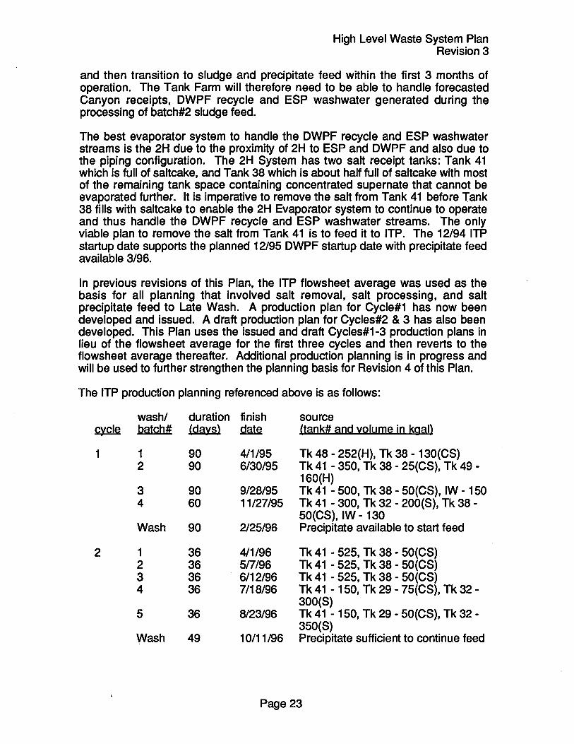
In previous revisions of this Plan, the ITP flowsheet average was used as the basis for all planning that involved salt removal, salt processing, and salt precipitate feed to Late Wash. A production plan for Cycle#1 has now been developed and issued. A draft production plan for Cycles#2 & 3 has also been developed. This Plan uses the issued and draft Cycles#1-3 production plans in lieu of the flowsheet average for the first three cycles and then reverts to the flowsheet average thereafter. Additional production planning is in progress and will be used to further strengthen the planning basis for Revision 4 of this Plan.
The ITP production planning referenced above is as follows:
washl duration finish source ~ batch# (days) ~ (tank# and volume in kgal)
1 1 90 4/1/95 Tk 48 - 252(H), Tk 38 - 130(CS) 2 90 6/30/95 Tk 41 - 350, Tk 38 - 25(CS), Tk 49 -
160(H) 3 90 9/28/95 Tk 41 - 500, Tk 38 - 50(CS), IW - 150 4 60 11/27/95 Tk 41 - 300, Tk 32 - 200(S), Tk 38 -
50(CS), IW - 130 Wash 90 2125/96 Precipitate available to start feed
2 1 36 411196 Tk 41 - 525, Tk 38 - 50(CS) 2 36 5n/96 Tk 41 - 525, Tk 38 - 50(CS) 3 36 6/12/96 Tk 41 - 525, Tk 38 - 50(CS) 4 36 7/18/96 Tk 41 - 150, Tk 29 - 75(CS), Tk 32 -
300(S) 5 36 8/23/96 Tk 41 - 150, Tk 29 - 50(CS), Tk 32-
350(S) Wash 49 10/11/96 Precipitate sufficient to continue feed
Page 23

High Level Waste System Plan Revision 3
3 1 36 11/16/96 Tk 41 - 600, Tk 29 - 25(CS) 2 36 12122/96 Tk 41 - 575, Tk 29 - 30(CS) 3 36 1/27/97 Tk 41 - 300, Tk 29 - 175, Tk 38 -
50(CS), IW - 50 4 36 314/97 Tk 27 - 100(CS), Tk 28 - 1 OO(CS), Tk
29 - 175, IW - 150 Wash 49 4/22197 Precipitate sufficient to continue feed
4 1 36 5/28/97 Tk 41 - 475, Tk 38 - 50(CS)
The first two batches work off the waste heels (shown with an "H" suffix) in Tanks 48 and 49 that remain from the 1983 ITP Demonstration blended with some Tank 41 dissolved saltcake (no suffix) and some concentrated supernate from Tank 38 (shown with a "CS" suffix) These are small volume batches increasing in size from about 400,000 gallons to the flowsheet average of about 800,000 gallons so that ITP can ensure adequate mixing in Tank 48. Some inhibited water (shown as "IW") is needed during the early batches to adjust the sodium molarity in Tank 48 as there is no ITP recycle water yet from Tank 22 to perform this function (the precipitate washing step has yet to occur). Unconcentrated supernate (shown with a "s" suffix) from Tank 32 is also consumed in Cycle#1. The direct feed of concentrated and unconcentrated supernate feed to ITP is used to adjust chemistry as well as to generate space in the evaporator systems.
The duration of each batch in Cycle#1 is planned to be 90 days, with the exception of batch#4 which is 60 days, versus the long term flowsheet average of 36 days. The additional time is an allowance for the initial startup of a one-of-akind facility and a planned technical evaluation at the end of each batch filtration. Likewise, the wash step is planned to require 90 days vs 49 days to accommodate the post-wash evaluation. The normal flowsheet is 3 batches at 36 days each plus one wash at 49 days for a total of 157 days per cycle. Due to the low cesium and potassium concentration in these first three cycles, additional batches are planned into each cycle before the wash occurs. This has the effect of accelerating salt removal from Tank 41.
Cycle#2 consists primarily of Tank 41 dissolved salt with concentrated supernate from Tank 29 and unconcentrated HHW from Tank 32. The concentrated supernate in Tank 29 must be removed before salt removal can commence in Tank 29. This waste also increases the Curie content of the precipitate without exceeding the 36 Ci/gallimit in the ITP process. Some inhibited water is needed in Cycles 2 and 3 as there is not enough ITP washwater available in Tank 22.
Cycle#3 is similar to Cycle#2 with concentrated supernate coming from Tanks 27, 28, 29 and 38. All of this waste creates tank space in their respective evaporator systems. Cycle#4, batch#1 completes the salt removal from Tank 41. As a contingency, a heel of saltcake can be left in Tank 41 if salt tanks in the 2F or 1 H/RHLWE evaporator systems must be emptied sooner than currently planned.
Page 24

High Level Waste System Plan Revision 3
Precipitate is available at the end of the Cycle#1 wash in quantities sufficient to initiate and sustain feed to Late Wash. There is the ability to vary the feed to ITP to generate more precipitate earlier if required by feeding concentrated supernate from tanks that have higher cesium and potassium concentrations than Tank 41. This has the effect of delaying salt removal from Tank 41 as more frequent washes will be required. Salt removal from Tank 41 can be accelerated by feeding primarily Tank 41 dissolved salt and thus enabling more batches to be processed before a sufficient quantity of precipitate accumulates that must be washed.
Currently, the precipitate level in Tank 49 is administratively limited to 565,000 gallons assuming the design average radionuclide concentration of 39 Ci/gal. This limit is based upon the rate of flammable gas generation in an unventilated tank and the assumption that three days may be required to re-establish tank ventilation after a seismic event. This 565,000 gallon precipitate level will be attained by FYOO. This Plan assumes that corrective actions will be defined and implemented prior to that time to enable the operating limit in Tank 49 to increase to the normal tank capacity of 1,300,000 gallons.
The chart in Appendix J.5 entitled "Tank 49 Precipitate Balance" shows the Tank 49 material balance and is based on the planned feed to ITP described in this section and in Section 8.7.1 and the planned "ready for hot operations" date for Late Wash of 3/96 with precipitate feed introduced to DWPF in 3/96. There are several points to note from the chart:
- the "sawtooth" shape of the curve shows the precipitate transfers from Tank 48 to Tank 49 at the end of each wash (nominally every 157 days) followed by the steady drawdown of feed to Late Wash,
- the bulk of the precipitate comes from the concentrated supernate feed thus the timing and amount of supernate feed must be carefully planned to avoid filling Tank 49 to the 565,000 gallon limit thus forcing ITP to slow down or shut down, and
- the "need" date for Late Wash startup appears to be late FYOO, however, the precipitate level in Tank 49 remains high and actually increases after FYOO and does not start to decrease until the HLW System attainment increases during batch#2 feed which suggests that a 1996 Late Wash startup is closer to the real "need" date
It should be noted that the Tank 41 dissolved salt is projected to have an excessively high concentration of chromium based on the limited samples taken to date. The chromium, if not allowed to settle out of the dissolved salt solution prior to Tank 48, will remain with the precipitate stream in the ITP process and thus be incorporated into glass. There is sufficient chromium to exceed the limit in glass. It is expected that additional salt samples from deeper in Tank 41 will show the presence of chromium to be anomolously high in the top layer of salt which would resolve this issue.
Another issue is the presence of insoluble solids in dissolved salt. Solids can be in the form of sludge or sulfate. Tank 41 sample analyses indicate that sulfate in
Page 25

High Level Waste System Plan Revision 3
the dissolved salt will exceed the Tank 48 process requirement for insoluble solids. This can result in reduced filter performance. As with chromium, the sulfate can be removed from dissolved salt by settling before transfer into Tank 48. The use of Tank 40 has been discussed in the past as a place to accumulate large batches of ITP feed. Tank 40 now becomes crucial to the ITP process as it is the only viable tank to stage the Tank 41 dissolved salt in to allow the insoluble solids to settle before transferring to Tank 48.
8.3 Extended Sludge Processing
ESP started the Process Verification Test 7/93 under the direction of the ITPIESP Startup Test Group. A Test Plan is being used to govern the testing to gather data required to define long term operating parameters for the ESP Facility. The data will be obtained during the course of two washes in Tank 42 and three washes in Tank 51. This is projected to be sufficient to prepare the batch#1 sludge feed for DWPF based on previous sludge sample analysis.
The slurry pumps in Tank 51 have been started up and operated. The slurry pump seal leakage experienced in Tank 51 thus far has been greater than expected. PVT data indicate actual leakage on the order of gallons per minute or tenths of a gallon per minute versus the expected cc's per minute. A task team has been formed to address this problem as the PVT proceeds. Vendor and industry experts have participated in this effort. Initial recommendations have been implemented. Others are long term in nature and will be evaluated for incorporation into the next generation of slurry pumps.
The Tank 42 pumps have been started and briefly operated. Initial data on seal leakage and vibration analysis has been within specifications. Inhibited water has been transferred into Tank 42 to initiate the first wash in that tank.
The ESP PVT will generate about 1,400,000 gallons of washwater in four separate transfers. There is currently insufficient space in the 2H Evaporator System to accommodate the four large washwater transfers out of ESP. The first two of these transfers will therefore be routed to Tank 21 or 24.
Thus far, the PVT has generated excellent sludge suspension, sludge settling and temperature data. Batch#1 washing is projected to be complete 3/95 with all sludge consolidated in Tank 51 one month later. There is about 10 months of float in the sludge preparation activity. DWPF will be ready for the first sludge transfer 2/96 per Test Plan FA20.01.
The sludge in Tank 42 will be transferred to Tank 51 at the completion of washing batch#1. Tank 42 will then become the emergency spare tank volume in H-Area until it is required to start receiving sludge from Tanks 11 and 15 as part of sludge batch#2. This is shown in Appendixes J.3 and J.4.
Page 26

8.4 Evaporators
High Level Waste System Plan Revision 3
There are two evaporators that are planned to be used to volume reduce the various waste streams coming into the Tank Farms: 2H and 2F. The previous revision of this Plan was based on the operation of the 1 H Evaporator in addition to 2H and 2F. This is no longer the plan as stated in Section 8.4.1. The 1 F Evaporator is also not planned to be operated. The 1 H must be out of service by 1/1/98 as required by the Tank Farm Wastewater Operating Permit. The RHLWE is currently scheduled to start up 11/97.
The evaporators play a crucial role in the HLW System. Because the evaporators were shut down in April and May, 1993 to enable Conduct of Operations improvements to be made, it is generally accepted that the evaporators and ITP will be the limiting factors in the near term governing the startup of the DWPF and therefore the HLW System. The long term need for the evaporators is to build contingency and operating flexibility into the Tank Farm operation by recovering tank space and to support higher HLW System attainment.
The goal for the evaporators is to have the Tank Farm in a position where the Tank Farm can be deemed "ready to support DWPF startup" by 12/95. This state of readiness can generally be described as:
- ITP started up and running well, - salt removal projects proceeding on schedule, - salt space available in each evaporator system, - tank space available in each system to receive the ESP washwater and
DWPF recycle streams, and - adequate tank space to receive the high volume ESP and DWPF waste
streams during routine and non-routine Tank Farm operations with a high degree of confidence
A key planning variable is the assumption for the amount of tank space that is needed at the time of DWPF startup. The DWPF recycle stream is regarded in this Plan as a stream that cannot be "turned off" if there are evaporator problems. This is due to the negative effects of thermally cycling the DWPF melter. This drives the Tank Farm to recover a significant amount of tank space that will permit DWPF to continue operating if the Tank Farm has some serious upset condition, such as an evaporator pot failure or a technical problem that shuts down all evaporators for an extended period of time.
The Tank Farm goal is to have a total of at least 3,000,000 gallons of available tank space at the time DWPF starts up, not including tank space that must be held in reserve as emergency spare tank capacity should a waste tank fail. This value is proposed as the minimal contingency for unplanned events such as:
- prolonged evaporator outages - evaporator utility less than planned - space gain less than planned
Page 27
High Level Waste System Plan Revision 3
- additional pot failures beyond those expected - atankleak - ITP operating at less than its planned rate - the Separations Canyons or DWPF generating waste above forecast - changing Site missions, etc.
Most of the events listed above has occurred in the past at SRS. The Tank Farm should always be in a condition where it can support these unplanned yet reasonable upset scenarios.
Experience shows that total tank space in an evaporator system of less than 200,000 gallons is bordering on a "waterlog" condition. The evaporator system can be operated when waterlogged, however, it is very inefficient until more space is gained because of the following:
- the contents of the salt receipt tank must be frequently transferred back to the evaporator feed tank in small transfers,
- this frequency is about every 10 days when the tank space in the system is 200,000 gallons which does not allow the salt to completely cool in the salt receipt tank prior to transfer back to the evaporator feed tank, and
- the transfers back to the feed tank occur as the salt receipt tank is receiving salt concentrate from the evaporator
It could therefore be said that total tank space in the Type III Tanks must remain above 600,000 gallons, assuming an optimal distribution of tank space, to avoid a waterlog or gridlock condition for the entire Tank Farm. The 3,000,000 gallons recommended is not overly conservative given the high volume and intermittent streams that must be handled such as ESP decant water, ESP aluminum dissolution waste and ESP washwater. The washwater will routinely be about 400,000 gallons per batch while the other two ESP streams can be up to 900,000 gallons per batch. If 900,000 gallons of tank space is required to periodically receive waste from ESP and total tank space must not dip below 600,000 gallons, then total available tank space of 3,000,000 gallons at the time of DWPF startup is not overly conservative.
After DWPF starts up, the space gain from the 2F and 2H Evaporators and from ITP will not be sufficient during this period to offset the waste generation. The Tank Farm available tank space will decrease until the RHLWE starts up in 11/97. It is important to achieve the 3,000,000 gallons of available tank space by 12/95 in anticipation of the higher waste receipts thereafter.
Evaporator space gain is defined as the difference between evaporator feed and evaporator concentrate corrected for flush water and chemical additions necessary to operate the evaporator system. Planned utility and space gain for each evaporator system, based on historical averages, is as follows:
Page 28

~
1 H Evaporator 40% 2H Evaporator 60% 2F Evaporator 60%
Total
High Level Waste System Plan Revision 3
historical planned space gain space gain (gallyr) (gallyr)
757,000 0 1,538,000 1,250,000 1.230.000 1.000.000
3,525,000 2,250,000
The difference between the historical and planned space gain for each evaporator was qualitatively developed by the HLW System Integration Manager. The reasoning is as follows. The negative effects of the ever increasing age of the Evaporator facilities plus the increased duration for routine and unplanned maintenance should be partially offset by the positive effects of the Conduct of Operations improvement program and the large backlog of unevaporated waste.
The 1 H Evaporator is assumed to remain down and thus it will not achieve its historical space gain. The 2H Evaporator's high historical average is due to the large amount of washwater generated by the ESP demonstration in 1983 and 1984 plus the high H Canyon production in the mid-1980's. 2H will not have the large volume of dilute waste that it has had in the past. The future ESP washwater will be evaporated in both the 2H and 2F Systems. Thus, the 2H will probably not be able to sustain its historical average. The 2F Evaporator has a lower historical average space gain than 2H primarily because of the lack of dilute waste and low waste receipts in recent years from F Canyon. This will change in the future because 2F will evaporate the current backlog of unevaporated F-Area HHW plus assist the 2H Evaporator with the dilute DWPF recycle and ESP washwater streams.
The historical average is an appropriate and somewhat aggressive planning basis for each evaporator system to attain in the future for three reasons: 1) in the past, the Canyon receipts were over 3,000,000 gallons per year of fresh waste versus the concentrated feed that is currently in the 2H and part of the 2F Evaporator systems, 2) in the past, two salt receipt tanks were alternately filled and decanted to the evaporator feed tank versus the one salt receipt tank available now in each system, and 3) the response to upset conditions or needed maintenance was prompt, albeit somewhat undisciplined, versus the disciplined conduct of operations program currently being implemented. Over the long term, the more disciplined operations should help increase space gain although it may tend to reduce space gain initially.
There are several pOints to note from the "Total Available Space" chart in Appendix J.3. Available tank space at the start of DWPF operations will be about 3,300,000 gallons and is prOjected to remain between 2.4 and 4.2 million gallons. Also evident on the "Total Available Space" database in Appendix J.4 is that the net gain in tank space due to evaporator operation alone is insufficient to offset the Tank Farm influent. A significant amount of space gain occurs as a result of feeding ITP concentrated supernate or emptying a salt tank by feeding it to ITP.
Page 29

High Level Waste System Plan Revision 3
Also note that the Tank Farm loses space while sludge batch#2 washing occurs even with the benefit of the RHLWE.
8.4.1 1 H Evaporator
The 1 H Evaporator was shut down in 1988 for hardware repairs and other upgrades as well as improvements to operator training and operating procedures. It was restarted on 3/8/93 and ran until 4/13/93 when an operating incident occurred in the Concentrate Transfer System (CTS) Heating and Ventilation (H&V) System. The 1 H Evaporator remained down until 12193 when it was restarted. It operated sporadically until 3/94 when the tube bundle failed an annual hydrotest.
A comprehensive evaluation was conducted to develop a recovery plan to compensate for the loss of projected space gain and to recommend the path forward for the 1 H Evaporator (Le., to replace the vessel or abandon it in place). The evaluation was based on supporting critical Site and HLW Division missions. There were six initial recommendations:
- replace the vessel and restart the evaporator by 12194, - acquire the use of Tank 24 for dilute waste storage and staging. - acquire the use of Tank 40 by accelerating modifications to the Tank 40
Valve Box, - reduce the RBOF impact to the Evaporators and Type III Tanks to zero, - do not add the Reactor Basin sludge to Type III tanks, and - take advantage of the 1 H Evaporator outage to complete NWTF and
RHLWE tie-ins that would have caused downtime in the 1 H operation
At the time that the recommendations were briefed to WSRC and DOE management, it was stated that the recommendation to replace and restart the 1 H Evaporator would be changed if the Separations waste forecast could be revised to reflect the effects of the current NEPA activities. It was not possible at that time to revise the forecast. In late 4/94, a decision was reached to change the forecast to show F-Canyon restart 8/94 and H-Canyon restart 10/95. This change affords the ability to leave the 1 H Evaporator down while still supporting all HLW and Site missions.
The current recommendations regarding the 1 H Evaporator are to implement the last five recommendations listed above while developing and implementing a plan to have a vendor perform the 1 H andlor 2H Evaporator pot replacement. The decision to replace the 1 H will be deferred until cost and schedule information are available. At this time, the 2H and 2F Evaporators are projected to be able to support the HLW Mission. In all likelihood, and based on current plans, the 1 H Evaporator will remain down and the 2H Evaporator vessel will be replaced in a planned outage using the vendor package or by WSRC personnel.
The current backlog of unevaporated HHW in the 1 H Evaporator system will remain in Tanks 13, 29-32, 35-37 and 39. While the 1 H Evaporator is planned to
Page 30

High Level Waste System Plan Revision 3
remain down, this evaporator system does contribute to the available tank space as follows:
+448 tank space available 5/1/94 -84 H-HHW from 5/1/94 - 12/29/95
-150 1 H Evaporator decon solution and flush water prior to 12129/95 +0 transfers to the 2F Evaporator system prior to 12129/95
+200 Tank 32 supernate feed to ITP prior to 12129/95 ~ space gain by evaporation from 5/1/94 - 12129/95
+414 net space available 12129/95
8.4.2 2H Evaporator
The primary role of the 2H Evaporator will be to evaporate the 221-H Canyon Low Heat Waste (LHW) stream, Receiving Basin for Offsite Fuel (RBOF) waste, the future DWPF recycle stream and ESP decant and washwater to the extent possible. The forecast for the RBOF stream has been reduced in this Revision of the Plan. Further reductions may be possible after successful completion of a Test Plan covering the direct feed of RBOF waste to the Tank 32 CRC. The Test Plan schedule is being developed.
The Canyon, RBOF and DWPF streams are expected to be very steady and therefore easy to plan. Small batches are received on two or three day intervals. The two ESP streams are exactly the opposite: large in volume and spaced one to four months apart. Large transfers will therefore be necessary out of the 2H System to the 1 H/RHLWE and 2F Systems. As an example, a 832,000 gallon transfer is shown below from the 2H System to Tank 21 or 24. This is necessary as ESP generates washwater in 350,000 gallon batches at a time when the 2H Evaporator system is nearly full of other waste. The washwater stored in Tank 21 or 24 can be used later as washwater for early washes of batch#2 sludge or salt dissolution water for Tank 29 salt.
In the near term, it is crucial that the 2H Evaporator system gets into a position where it can support completion of ESP batch#1 washing and DWPF recycle starting 12129/95. This position is defined as follows:
the 2H Evaporator is running, ITP started up and running at a rate to complete Tank 41 salt removal before Tank 38 is filled with salt, available salt receipt space in Tank 38 to last until Tank 41 is empty and returned to salt receipt service, and available tank space of 200,000 gallons (the minimum required to operate any evaporator system efficiently)
The planned 2H operation that would support DWPF startup 12/29/95 is based on a planned utility of 60% with a space gain of 104,167 gallons per month:
Page 31

+585 -345
-1,000 -1,407
+255 +832
+1.458
+378
space available 5/1/94
High Level Waste System Plan Revision 3
projected H-LHW 5/1/94 - 12129/95 RBOF transfers into the 2H System 5/1194 - 12129/95 remainder of ESP washwater to complete batch#1 washing concentrated waste transfer to ITP prior to 12129/95 ESP washwater transfer to Type IV tanks prior to 12129/95 space gain by evaporation 5/1194 - 12129/95
space available 12/29195
It is important to note that the success of this evaporator system is partially dependent upon the transfer of concentrated waste to ITP via Tank 40 and on the transfer of ESP washwater to Tank 21 or 24. Neither capability exists at this time however both are planned to be attained in late 1994.
8.4.3 2F Evaporator
The 2F Evaporator was restarted 3/94. The operation was sporadic due to a thick layer of concentrated caustic liquor in the feed tank. The feed pump could not maintain its prime and the evaporator was shut down 4/94. Since that time, the following actions have been taken to improve the feedstock as well as the ability to transfer waste into and out of the feed tank:
the evaporator feed pump was replaced, the feed pump eductor was replaced, the feed tank transfer jet was replaced, the concentrated waste was transferred to Tank 46, and fresh HHW was transferred into the feed tank
The evaporator resumed operation 5/17/94 and was operating well at the time of this Plan. The space gain should meet or exceed the planned space gain of 83,333 gallons per month required to support this Plan.
In the past, all F and H-Area HHW was evaporated in the 1 H Evaporator. Due to the large backlog of unevaporated HHW in F and H-Areas as well as the planned new H-Area waste loads from ESP and DWPF, a technical evaluation was performed to determine the requirements to evaporate HHW in the 2F Evaporator system and to drop the evaporator concentrate in Tank 46. It was determined that this was feasible. A program was then initiated to make the necessary alterations on 2F and Tank 46. This program has since been completed and waste is being placed in Tank 46 for the first time.
The primary role of the 2F Evaporator will be to evaporate 221-F Canyon LHW, HHW and the 2,100,000 gallon backlog of F-Area HHW in Tanks 33 and 34. Once this is complete, 2F's role will transition to becoming the primary HHW evaporator for F and H-Area HHW while keeping current with F-Canyon LHW waste receipts and assisting the H-Area evaporators with the DWPF recycle and ESP washwater streams as possible. Transfers from H-Area to F-Area will not
Page 32

High Level Waste System Plan Revision 3
be possible until the NWTF starts up 11/95. The necessary instrumentation and process control functions for H to F transfers do not currently exist. In the near term, it is crucial that the 2F Evaporator system gets into a position where it has worked off all available F-Area feed and can support the 1 Hand 2H systems as needed after DWPF startup and during ESP batch#2 washing. This position is defined as follows:
the 2F Evaporator is running, Tank 46 is in use receiving 2F evaporator concentrate from HHW Tanks 33 and 34, and available salt receipt space in Tanks 27 and 46 to last until Tank 25 is empty and returned to salt receipt service
2F utility is planned to be 60% with a space gain of 83,333 gallons per month during the planning period. Planning for this system is as follows:
+1,516 -1,300
-487 -85
+1.625
+1,269
tank space currently available 5/1/94 (kgal) reserve for emergency spare tank space F-LHW from 5/1/94 to 12/29/95 F-HHW from 5/1/94 to 12129/95 space gain by evaporation 5/16/94 - 12129/95
net space avai lable 12129/95
8.4.4 Replacement High Level Waste Evaporator
The RHLWE is currently in the design and construction phase. The planned startup date is 11/17/97. The Total Estimated Cost (TEC) portion of the project is proceeding on schedule. The OPC portion is currently behind schedule due to the loan of OPC personnel in FY94 to higher priority programs. The loaned personnel have started to return and have validated that the 11/17/97 startup schedule is achievable. Evaluations are being conducted to accelerate the startup. Preliminary indications are that acceleration is possible if additional manpower, and therefore funding, can be made available in FY95-96.
The RHLWE is planned to operate at 80% utility and at a space gain of 270,000 gallons per month. This space gain value, unlike the others, is not based on historical averages as this is a new design and a higher capacity evaporator. The design basis is 7,600,000 gallons per year of overheads assuming feed at 33 gpm at 25-35 % dissolved solids. From this figure, engineering estimates were used to determine the number and volume of flushes, desalt-descale operations, chemical additions, etc., all of which are deducted from the overheads value to calculate space gain.
Revision 2 of this Plan discussed the need to have Tank 29 empty, the cooling coils replaced and the tank returned to salt receipt service to support the 11/17/97 startup. In fact, Revision 2 projected that Tank 29 would not be ready until 8 months later. This is no longer an issue. Because the 1 H Evaporator will
Page 33

High Level Waste System Plan Revision 3
remain down, Tank 30 will not be filled with salt. It will be available for salt receipt from the RHLWE 11/17/97. Tank 29 will be empty 12 months before Tank 30 is filled. The cooling coils in Tank 30, similar to Tank 29, should be replaced before the tank starts filling with salt. This is not planned or budgeted at this time.
Given all of the planning bases, issues, assumptions and contingencies described in this Plan, 11/17/97 is an acceptable startup date. The justification for this project has been the subject of ongoing reviews and is therefore not a primary objective of this Plan, however, the two charts in Appendix J.3 and J.4 clearly show that the RHLWE (or some other form of space gain) is needed to support the long term operation of the HLW System, particularly at attainments above the 38% planned for batch#1 sludge feed. The two charts are also backed up by several pages of text that describe the evaporation needs opposite planned future System attainment.
8.5 Waste Transfer Facilities
8.5.1 New Waste Transfer Facility
The startup schedule shown in Revision 2 of this Plan was a "need date" based schedule. The baseline schedule at that time was obsolete as personnel were loaned to other higher priority programs. The loaned personnel have since returned and a newly rebaselined startup schedule has been developed and transmitted to DOE-SA. The new startup date is 11/29/95. This date will support the start of the DWPF Spike Test per test plan FA18.01.
Leading up to the planned 11/95 startup date, the following is planned to be successfully completed: startup testing, resolution of pump vibration issues, a Readiness Self Assessment, some of the tie-ins, the WSRC ORR, the DOE ORR, remaining tie-ins, post tie-in verifications and finally, approval for hot startup.
In the past, the NWTF was to be used to transfer the DWPF mercury recycle stream to the Tank Farm. OngOing development work by the Savannah River Technology Center (SRTC) and DWPF Engineering indicates that sending the mercury recycle to the ETF is technically feasible and operationally achievable with only minor modifications. This has the advantage of not burdening the Tank Farm evaporators with about 190,000 gallons of DWPF simulant. Another advantage is that DWPF could possibly continue testing beyond the planned 190,000 gallons with no impact to the Tank Farm.
Transferring or trucking the mercury recycle waste to the Tank Farm or to a vendor supplied process will remain active as contingencies to ETF.
Jumper changes in other diversion boxes connected to the NWTF continue to be planned at the time of this report. These are not new activities. The jumper changes will cause localized outages in parts of the H-Tank Farm facility that
Page 34

High Level Waste System Plan Revision 3
could impact ITP, ESP and Evaporator operations. There is coordination between the various facilities intended to minimize or eliminate the impacts. This subject requires additional planning and coordination and is managed within HLWand reported in the weekly HLW Plan of the Week meetings. At this time, it appears that the impacts can be managed.
8.5.2 F to H-Area Interarea Line
The F to H-Area Interarea Line (IAL) connects the F-Area and H-Area Tank Farms. A description of the IAL is contained in Appendix A. All F-Area waste must be transferred through the IAL to be processed in ITP or ESP. Some of the dilute waste streams and all of the future H-Area HHW prior to 11/17/97 will be transferred to the F-Area Tank Farm via the IAL. The maintenance and operation of the IAL is therefore critical to the HLW Mission.
At this time, the capability does not exist to transfer waste from H-Area to F-Area or vice versa due to deficiencies in the process control instrumentation. When the NWTF starts up in 11/95, H-Area to F-Area transfers will be possible and are planned. These transfers will enable the 2F Evaporator to evaporate the existing backlog of H-Area HHW. The 2F Evaporator will have processed the backlog of available feed in F-Area by 5/96 and will be available for feed from H-Area by that time.
F-Area to H-Area transfers cannot start until the process controls in F-Area are upgraded. This upgrade is not part of any existing project. It is assumed to be a future Division Managed Task. The scoping and engineering studies have been initiated, however, progress has been impeded by other higher priority programs such as manning the ITP outage and assisting with the Evaporator restarts. There is not a complete scope, schedule and estimate for this task at this time. The need date for this activity to be complete is based on the need to transfer Tank 25 dissolved salt to ITP. This is projected to occur in late 1996. This is an open issue and is listed as such in this Plan (see Appendix G.1).
There was a Line Item project to upgrade the IAL. The scope of that project was to install a containment building and remotely operated crane on the high point vent valve box (a small diversion box-type structure mid-way between the F and H-Area Tank Farms). The justification for this project was based upon improved contamination control, particularly alpha contamination, during maintenance. This project did not involve replacing the IAL or any significant piping modifications. A FY93 Reprogramming action cancelled this project and reallocated the funding to Late Wash. The basis for cancelling the project was the infrequent need to perform maintenance in the high point vent valve box and the need to fund Late Wash.
Page 35

8.6 Diversion Box & Pump Pit Containment
High Level Waste System Plan Revision 3
This project will install a ventilated building and remotely operated bridge crane over HDB-7. HDB-7 is the most utilized diversion box in the Tank Farm and is the hub for all transfers into ITP, ESP and the 2H Evaporator System. The schedule used here is the project baseline schedule which shows construction activities complete 3/30/95. Three months are allowed for completion of OPC activities thus setting radioactive operations at 6/30/95. The OPC fragnet shown is based on a rough estimate rather than on a resource loaded OPC schedule. The OPC portion of the schedule is yet to be defined.
All significant interferences with other facilities will be identified and included in the HLW System Integrated Schedule. One potential interference is shown on the schedule; that being from the time building steel is erected 6/9/94 until the Rad Ops date of 6/30/95. A jumper failure such as a leak or damaged valve during this period could impact construction if it was determined that repairs must be made. This period of time is called the "Window of Vulnerability" on the Integrated Schedule. The duration of this window can be reduced through detailed planning, i.e. maximizing the time where a yard crane could be used and by accelerating the availability of the building crane. The latter would require some form of agreement ahead of time to allow limited operation prior to completion of all readiness review activities. There is potential to reduce the window to a few months; this effort will be manned as part of the OPC above.
8.7 Waste Removal
The cost and schedule used in Revision 2 of this Plan was virtually obsolete. Waste Removal Program (WRP) personnel were on loan to other higher priority programs thus there was insufficient manpower to strengthen the schedule. Loaned personnel have started to be returned to WRP. The cost, scope and schedule of the Waste Removal Program was recently rebaselined in preparation for the upcoming Energy Systems AcquiSition AdviSOry Board (ESAAB) action. The current WRP baseline is much stronger than in the past and represents an excellent planning base. This is crucial to the accuracy and quality of this HLW System Plan as the WRP is the most highly integrated of anyone of the HLW programs or projects.
Other benefits from the recent rebaselining are as follows:
- a graded startup approach was developed and defended to WSRC and DOE which resulted in a significant cost and manpower savings,
- detailed planning in the out years enabled many tanks to be ready for waste removal from one to ten years earlier than projected in Revision 2 of this Plan,
- a conceptual strategy of consolidating waste from old tanks to new tanks in F-Area could result in additional schedule improvement,
- the possibility exists to partially wash some of the F-Area sludge in-situ before transfer to ESP thus reducing the evaporator load in H-Area,
Page 36

High Level Waste System Plan Revision 3
- similar strategies are possible in H-Area, and - the possibility exists, via waste consolidation as described above, to shut
down large sections of the Tank Farm prior to 2018
While the cost savings derived from the graded approach to startup are real and incorporated into the WRP, the other benefits listed above are still conceptual and will require detailed planning to fully develop. There is no question, however, that waste removal from some old-style tanks can be accelerated ahead of the dates shown in this Plan assuming that funding is provided as requested. The "ready for waste removal" dates are shown graphically on the chart in Appendix C.1 and C.2. The delta from the ready for waste removal date and the planned start of waste removal can be seen clearly. The larger the delta, the greater the potential for acceleration of the waste removal schedule for that tank. The potential to accelerate waste removal from the old-style tanks will be developed and described in Revision 4.
It is most important to note that the waste removal schedules shown in this Plan, the FY96 FYP and the upcoming ESMB are based on a projected funding profile for the WRP that exceeds the funding allocated to the WRP in the FY96 FYP. This was done per the guidance of DOE-SR and is shown below:
System Plan/FY96 FYP 38.9 43.2 WRP Baseline ~ ~
Delta -10.6 -9.2
47.1 63.4 62.2 ~ &.2 ~
-9.5 2.8 14.2
00
66.1 ~
22.3
The table above shows that there is inadequate funding in FY95-97 to support the schedule and excess funding by the end of the planning period. The presumption is that areas for additional cost savings will be identified in all programs and thus enable funding to be directed to the WRP to eliminate the projected shortfall.
It is also important to note that the projected waste removal date for the old-style tanks are at least ten years ahead of the schedule submitted to SCDHEC 11/12/93. This is due to the conservative funding assumptions used to develop the FFA Waste Removal Plan and Schedule.
8.7.1 Salt Removal
Tank 41 will be the first salt tank fed to ITP. There are still outstanding criticality issues specific to Tank 41 due to the relatively high concentration of fissile U and Pu. The concern is that insoluble fissiles can concentrate in low spots in the salt formation inside Tank 41. Previous sampling and analytical studies indicate that the majority of U is soluble and that initiation of salt dissolution can safely proceed. There has been limited progress in this area since Revision 1 of this Plan. Additional salt samples have been taken from the top 12 inches from Tank
Page 37

High Level Waste System Plan Revision 3
41 and analyzed. Further sampling was stopped due to lack of funding and increased emphasis on ITP startup. As before, there is a strong need to feed Tank 41 to ITP as soon as possible in order to maintain the operation of the 2H Evaporator. While salt dissolution in Tank 41 can be safely initiated, it is still not known if all of the salt can be removed, the size of the batches or the rate of salt removal. Additional sampling and analyses are necessary to characterize the tank contents. The planning basis is that all of the salt will be removed from Tank 41 and fed to ITP prior to raising the pumps and preparing the tank to return to salt receipt. This will be accomplished through salt sampling followed by controlled dissolution batches based on sample results.
Salt removal from Tank 41 is scheduled to begin 4 months prior to ITP startup. This is necessary to ensure that there will be an adequate supply of Tank 41 dissolved salt to feed to ITP in the first several batches. The initial salt removal from Tank 41 will be slow due to the lack of working capacity in the tank and the sampling requirements. As salt is removed, larger and larger salt removal batches can occur. As stated in Section 8.2, Tank 40 must be available to stage the dissolved salt from Tank 41 to allow the insoluble solids to settle prior to transferring to Tank 48.
There will be alternate feeds to ITP during and after processing of Tank 41, i.e., feeding existing concentrated supernate directly to ITP. A caustic rich liquor accumulates in evaporator systems that cannot be further evaporated. This concentrated supernate takes up space in the evaporator system that could be used to form saltcake. Currently, there are significant quantities of concentrated supernate in the 2F and 2H Systems. It has been determined that Tanks 26, 27, 29, 30, 38 and 43 can be fed to ITP without excessive dilution or criticality concerns. Alternate feeds must be very carefully planned as they contain from four to ten times the potassium concentration versus the ITP feed flowsheet average, thus they generate large quantities of precipitate which rapidly fill Tank 49.
Tank 29 Salt Removal
Tank 29 is the second tank to be fed to ITP. Now that the 1 H Evaporator is planned to remain down, the RHLWE will start up dropping salt concentrate to Tank 30 instead of Tank 29. Tank 30 is projected to be filled by 11/99. Tank 29 must therefore have all of the salt removed, the cooling coils replaced and the tank returned to salt receipt service by 11/99. The Tank 29 concentrated supernate and subsequent dissolved salt will increase the Curie content of combined Tank 41/29/38 precipitate to something close to the 36 CilgallTP limit. This is important because H-Area has very little LHW salt that can be used to blend with HHW salt. Processing straight Tank 41 salt solution to ITP effectively reduces the available stock of blending material for HHW salt. Tank 29 concentrated supernate will therefore be "metered" into the ITP feed stream to avoid inefficiencies in future operations.
Because Tank 29 will be the first tank to undergo the waste removal graded startup process, it is often referred to as the "Programmatic Waste Removal
Page 38

High Level Waste System Plan Revision 3
Tank". The OPC portion of the startup schedule is longer and more costly than succeeding tanks. Startup is scheduled to occur 6/96. This individual tank schedule is one of only two that slipped vs Revision 2 of this Plan (the other is Tank 38) while the other 40 tanks have met or improved their previous schedules. The 6/96 date will support the RHLWE planned operation as Tank 30 will not be full of saltcake by the time Tank 29 is empty and returned to salt service.
Tank 25 Salt Removal
Tank 25 will be the third tank fed to ITP. Tank 25 must be empty and returned to salt service before Tanks 27 and 46 are filled with salt. Tank 25 will be ready for waste removal 10/96. Tank 25 dissolved salt will be blended with Tank 29 dissolved salt due to the high Curie content expected in Tank 29. Slurry pump run-in and installation, and completion of construction punch list activities comprise the bulk of the remaining TEC scope.
Tank 31 Salt Removal
Tank 31 will be the fourth tank fed to ITP. Placing Tank 31 this early relative to other tanks is necessary due to the high capacity of the RHLWE. Tank 31, like Tank 29, must also have the cooling coils replaced before it can return to salt receipt service thus increasing the demand to get this tank fed to ITP. There is no project scoped and budgeted for cooling coil replacement or return to salt service at this time. Evaluations are underway to more precisely determine cooling requirements for the RHLWE salt receipt tanks. At this time, it is assumed that Tanks 29-31 will require new cooling coils. TEC activities are just beginning on this tank.
Tank 38 Salt Removal
Tank 38 will be the fifth tank fed to ITP. It must be emptied before Tank 41 is refilled. Design is just beginning in FY94 with the capital funding portion of Activity Data Sheet (ADS) 314-U.
Tank 47 SaH Removal
Tank 47 will be the sixth tank fed to ITP. The driver for salt removal from this tank is to enable sludge removal to begin as part of sludge batch#3. The salt must be removed prior to sludge removal. Tank 47 contains the largest volume of sludge of any tank remaining after the batch # 1 and #2 tanks. This makes it a very economical source of sludge feed to DWPF. Due to budget constraints, it is very important to have this tank as part of batch # 3 to help keep System attainment as high as possible. TEC work is scheduled to begin FY95.
Other Salt Tanks
The remaining salt tanks to be fed to ITP are shown in Appendix J. While almost all of the first sixteen sludge tanks emptied were Old, the same cannot be said of the salt tanks. The needs of the Tank Farm to handle normal waste receipts combined with the need to handle sludge washwater and DWPF recycle dictate
Page 39

High Level Waste System Plan Revision 3
that those tanks that can be reused to store salt (Le., the new tanks) must be emptied first. Of the old tanks, only Tanks 17, 19, 20 and 24 (all Type IV tanks emptied in the mid 'BO's) will be emptied of salt before the turn of the century.
8.7.2 Sludge Removal
Sludge removal is performed in a manner that yields six discreet batches of sludge which will be individually segregated and characterized after pretreatment in ESP. Sludge batch#1 is currently in process in ESP Tanks 42 and 51. Sludge removal to support sludge batch#2 is several years away as the three tanks that will constitute batch#2 are in the early stage of equipment design and construction. The six batches are shown in Appendix J.2.
At the time of this Plan, the limiting factor for HLW System attainment was the ability to fund waste removal operations on the sludge tanks. The System attainment for the duration of the waste processing campaign will average 45% with a high of 73% for batch#3. Additional planning and forecasting are underway that could improve these projections for batches#3, 4 and 5 as the projected funding during that time period is limited only by the capability of the System to effectively use it to accomplish the earliest completion of the waste processing program.
8.8 Defense Waste Processing
The DWPF startup schedule remains the same as in Revision 2 of this Plan. DWPF achieved several important milestones since Revision 2. Construction was initiated on the Late Wash Pump Pit Modifications. The preparations for melter heatup were completed and the melter was at operating temperature and glass level at the time of this Plan.
8.8.2 Vitrification
The date at which WSRC declares readiness to start radiological operations in DWPF is 11/15/95. The DOE ORR is scheduled to be complete within 30 days or by 12/16/95. Two weeks are scheduled to complete resolution of findings thus setting radioactive operations at 12/29/95. The plant will start with simulant spiked with radioactivity under the guidance of the Joint Test Group and then transition to full radioactive operations with precipitate and sludge by 3/96. This schedule is shown in Appendix F. Note that there are two outages scheduled after radioactive startup for melter replacement. The life of a melter is estimated to be two years with five months for replacement and restart.
In the near term, the average attainment of DWPF, and therefore the HLW System, will be limited by the ability to provide the pretreated sludge feed. The consumption of batch#1 feed will occur from 2/96 until 11/01 for an average attainment of 36%. This is not to say that DWPF could not operate at a higher
Page 40

High Level Waste System Plan Revision 3
attainment and then shut down when the batch#1 sludge was completely consumed; only that the average attainment during batch#1 will be 36%.
Attainment is defined as the design capacity times the design utility of the DWPF plant. The design capacity is calculated as follows:
228 Ibs glass x can x 24 hr x 365.15 day = 540 ~ hr 3,705 Ibs glass day yr yr
Therefore, 540 cans/yr is the design capacity, sometimes referred to as the instantaneous or nameplate capacity, of the DWPF. The DWPF design utility is 75%. Therefore, the maximum long term average attainment is (.75) (540 cans/yr) = 405 cans/yr. This value is referred to as 75% attainment. Thus, looking at batch#3 in the table below, the planned attainment of 73% is approaching the maximum design attainment of 75%.
In the long term, attainment will average 45%. The attainment for each sludge batch and for the entire campaign is shown below:
glass batch glass attainment poured duration poured as % of 540
~ .atart (cans/batch) (years) (cans/yr) cans/yr (%)
1 2/96 1,112 5.75 193 36 2 11/01 782 3.67 213 39 3 7/05 1,513 3.83 395 73 4 5/09 971 3.33 292 54 5 9/12 774 4.25 182 34 6 12/16 441 ...2...QQ m ~
5,593 22.83 245 45
In the near term, funding for the batch#2 sludge tanks is the limiting item at 36%. If this were corrected, then the DWPF laboratory turnaround time would limit attainment to 40-45%. An action plan is being developed to improve turnaround time. The ITP cycle time currently limits long term attainment to 58%. Evaluations are underway to reduce the cycle time to support 75% long term attainment. Significant long term attainment increases will also require expediting cold chemical procurement as well as all of the repetitive projects in the HLW System such as: Saltstone Vaults, Vault capping, Vault permanent roofs, waste removal, Glass Waste Storage Building#2, and some Solid Waste projects that handle low level and mixed waste.
8.8.2 Late Wash Facility
Cost and schedule evaluations were underway at the time of this Plan. The low percentage of design available at the time of the original cost estimate led to a low estimate. Scope growth to meet the "assured confinement" criteria
Page 41

High Level Waste System Plan Revision 3
aggravated the problem, both in terms of cost and schedule. A comprehensive review of the entire scope of this project was recently completed with the objective of driving the TEC from $66 million down to the original $41.5 million and to rebaseline the schedule. At the time of this Plan, the TEC had been reduced to $41.5 million, the OPC was projected to be $33 million versus the budget of $17 million, and the startup schedule was projected to be delayed from 12/95 to 3/96. Rigorous reviews to improve the schedule and reduce the scope of the OPC activities continue. If Late Wash starts up 3/96, then only one month of "sludge-only" canisters (about 16 at the planned 36% attainment) will be produced.
8.8.3 Saltstone Facility
Though currently operating, the Saltstone facility will require construction of additional vaults, capping of filled vault cells and construction of permanent roofs. The required schedule for these repetitive projects is dependent upon the ITP production plan. As described in Section 8.2, this production planning process has been started and is providing accurate information to assist in vault planning. The timing of Vaults#2 and 3 supports the planned near term ITP production plan. The timing of out year vaults is based on the ITP flowsheet average. Saltstone recently successfully completed a planned three day production run to demonstrate that Saltstone could operate at the required rate to satisfactorily manage the inventory in Tank 50.
Currently, construction of Vaults#1 and 4 is complete and both vaults are in service. Vault #1 has 6 cells, 3 of which are filled; and Vault #4 has 12 cells, 1 of which is filled. Vault #4 is the prototype for future vaults which will have 12 cells per vault. The Vault #1 operating plan is as follows: as each cell is filled, a 1 foot thick clean concrete isolation cap is installed and the Rolling Weather Protection Cover (RWPC) is moved to the next set of two cells. When all 6 cells are filled, the RWPC is dismantled and discarded. The future operating plan will be changed starting with Vault#4. Preparation of design and procurement specifications for a permanent roof for Vault#4 are currently underway. The permenent roof, to be installed in FY95, enables the RWPC installed on Vault #4 to be dismantled as clean waste. This approach results in a significant cost savings.
8.9 Consolidated Incinerator Facility
The CIF is currently scheduled to be complete in mid-1995, followed by a trial burn in December 1995. The FFCA commitment is for radioactive operations to begin by 2/2/96 with the CIF running about 1 month ahead of this schedule. The CIF will become an integral part of the HLW System at the time when the 150,000 gallon Organic Waste Storage Tank at DWPF becomes full. Due to the low attainment in the early years of DWPF operation, there will be less cesium/potassium tetraphenyl borate fed to DWPF and therefore less benzene generated when compared to the long term average flowsheet. CIF is not
Page 42

High Level Waste System Plan Revision 3
expected to be required to support the HLW System until 1999, we" after its forecasted startup date. For this reason, the CIF is treated in a summary fashion in this document.
There are CIF concerns that could impact the HLW System operation. Currently, the CIF is preparing an Environmental Impact Statement (EIS) in para"el with continuation of construction of the facility. The EIS is not a prerequisite for radioactive operations at this time. The concern is that the EIS could become a predecessor which could delay the startup. Another concern is the DOE moratorium on incinerators. While this does not apply to the CIF because the CIF was started before the moratorium, there is a concern that this could change overtime.
8.10 New Facility Planning
A" planned new start projects pertinent to the HLW System are shown in Appendix N. These projects can be identified by the date as we" as the parent ADS designation (38-LI for HLW New facility Planning projects and 25-LI for DWPF). It is anticipated that not a" of the projects will be supported by DOE. The amount of funding for Conceptual Design Reports and other early project activities has been forecasted in the FY96 FYP accordingly. Projects that are not supported at the Target Level funding in the FY96 FYP are so noted.
The Saltstone Vaults, DWPF Glass Waste Storage Building, Replacement Glass Melters, and Failed Equipment Storage Vault projects have been deferred consistent with a "just in time" philosophy. There is some risk, albeit very sma", inherent in this approach particularly with the latter two projects as there is no actual operating data on the DWPF one-of-a-kind melters. The assumption of this risk was determined to be necessary to maintain the attainment of the HLW System as high as possible after DWPF startup. While this approach to balancing the projected funding generates significant funding for other programs, it also means that future attempts to accelerate System attainment must accelerate the entire series of each of these repetitive projects.
Also contained in the HLW New Facility Planning ADS is the funding for ongoing Ion Exchange (IX) studies. While the issue of Ion Exchange as a first generation ITP replacement has been closed, there are ongoing technical, project scoping and 1/2 scale Ion Exchange skid testing programs that are funded in FY94. SRS funding in the amount of $2,000,000 plus minimal additional funding from the DOE Office of Technology and Development (OTD) has enabled the following to to be initiated in FY94:
• Ion Exchange Skid Testing
An existing 20 gpm skid, previously bought using OTD funding, will be connected to support services and tankage and used to conduct test runs with waste simulating conditions at Hanford, Oak Ridge and SRS. The objective of the test program will be to determine resin physical strength, resin stability,
Page 43

High Level Waste System Plan Revision 3
hydraulic degradation, fines removal, column pressure drop, decontamination factors, resin life, elution characteristics, filtration attributes and resin removal. Construction turnover, equipment testing and water runs are scheduled to be complete by the end of December, 1994, with actual testing activities occurring throughout 1995.
• Ion Exchange Engineering Cost Estimate
The objective is to provide a bounding type cost estimate for a stand alone IX facility assuming that ITP starts up and operates for several years. This effort was stopped during 12/93 per DOE-SR guidance. There are no plans to resume at this time.
• DWPF Recycle Reduction
Studies are underway to develop a program suitable for release to a vendor that will couple GT-73 mercury removal resin with filtration to enable the DWPF mercury testing effluent to be processed at ETF in lieu of in the Tank Farm Evaporators. This will reduce the Tank Farm load by about 190,000 gallons of waste. Vendors are being solicited to determine whether this is a feasible option.
Additional studies have been completed with the objective of reducing hot DWPF recycle. A task team identified numerous potential reductions and sorted them into three categories based on ease of implementation. Work is proceeding to implement three of these options: use of concentrated simulated precipitate hydrolysis aqueous during periods of sludge-only operation, reduction or elimination of precipitate reactor heel pumpout, and implementation of a water conservation program. Other recycle reduction options will be pursued as process improvements after the start of DWPF Radiological Operations.
o RBOF Treatment
The Tank Farm receives a waste stream from RBOF that has averaged 30,000 gallons per month for the last 4 years. This stream is evaporated by the 2H Evaporator. The FY94 AOP for Reactors calls for this stream to be about 100,000 gallons per month in order to improve the Reactor Basin water quality. According to Separations Engineering personnel, 80% of the RBOF waste can be processed by the Separations GP Evaporator. Based on the above, 30,000 gallons per month is used as the planning basis in this document. This is down from the 50,000 gallons per month assumed in Revision 2 of this Plan.
In the past, this stream was mixed with 1 H Evaporator overheads and treated by a small Cesium Removal Column located in Tank 32. The treated effluent was then transferred to the ETF. This practice was stopped in the mid-1980's due to the excessive generation of spent zeolite resin. The cause of the decreased resin life was determined to be the high pH of the RBOF stream
Page 44

High Level Waste System Plan Revision 3
and the fact that the 1 H Evaporator was down most of the time. The overheads were therefore not available to dilute and lower the pH of the RBOF stream. RBOF has since revised their procedures to add less caustic prior to transfer to Tank 23 and thus drive the pH in Tank 23 down to about 10.
Recent studies by SRTC indicate that the existing zeolite resin should perform well at pH 10 or below. Operations personnel have walked down the equipment required to feed Tank 23 to the CRC. With minor work, the CRC system is ready to operate. At the time of this Plan, Engineering was developing a Test Plan and schedule to resume feeding Tank 23 directly to the CRC.
g.o Contingency Analysis
9.1 Programmatic Contingency
Uncertainties are listed in Appendix G.1. Programmatic Uncertainties are defined as those unknowns that do not involve resolution or definition of technical issues. In other words, the fix is known but there may be insufficient time, manpower or funding to implement the fix. Each is defined as an issue, assumption and contingency action(s).
9.2 Technical Contingency
Technical uncertainties are listed in Appendix G.2 as described above. The bulk of the technical uncertainties relate to the operation of the DWPF and ITP processes. The uncertainties are primarily emergent issues that were identified during cold chemical testing. There are a few issues concerning the interaction between facilities such as the ability to meet the downstream facilities' feed specifications.
The batch nature of the entire HLW System is very forgiving in this regard as each batch can be reworked, washed further, chemically adjusted, etc., before feeding to the downstream facility. Trim chemicals can also be added at DWPF.
It is important to recognize that each step in the HLW System has been demonstrated with the actual radioactive waste that is to be processed. The scale of the SRS demonstrations was huge by industry standards. The scale of the successful Extended Sludge Processing, In-Tank Precipitation and Waste Removal demonstrations were larger than the entire waste removal and processing programs at some other DOE sites. ESP processed 125,000 gallons of settled sludge; ITP produced 500,000 gallons of filtrate and Waste Removal has been performed in over 10 tanks with millions of gallons of salt and sludge removed and pumped through the 2.2 mile long Inter-Area Une.
Page 45


High Level Waste System Plan Revision 3
Appendix A - HLW System Description
High Level Waste
High Level Waste is defined as the highly radioactive waste material that results from the reprocessing of spent nuclear fuel. This includes liquid waste produced directly in reprocessing and any solid waste derived from the liqUid. The HLW contains a combination of transuranic waste and fission products in concentrations requiring permanent isolation.
SRS liquid waste, as received in the waste tanks, is made up of many waste streams generated during the recovery and purification of transuranic products and unburned fissile material from spent reactor fuel elements. These wastes are neutralized to excess alkalinity (pH 10 to 13) before transfer to the Tank Farm underground storage tanks.
HLW is segregated in the F and H-Area Canyons according to radionuclide and heat content. High Heat Waste (HHW) is primarily generated during the first extraction cycle in the Separations Canyon and contains a major portion of the radioactivity. Low Heat Waste (LHW) is primarily generated from the second and subsequent extraction cycles in the Canyons. HHW is aged at least one year in receipt tanks to reduce the concentration of short-lived radionuclides before evaporation.
A-1
Waste Tanks
Waste Management operates 51 waste tanks and 3 evaporators (a fourth evaporator has been retired and there are no plans to reactivate it) for the purpose of safely storing and volume reducing liquid radioactive waste. The major waste streams into the F and H-Area Tank Farms include HHW, LHW, receipts from RBOF, and DWPF recycle (future). Other major miscellaneous inputs internal to the Tank Farm include additions and byproducts of processes required for preparation of DWPF feed such as sludge washwater, sludge removal decant water, sludge aluminum dissolution washwater, tank interior and annulus spray washing, inhibitor additions for corrosion control, caustic used for aluminum dissolution, and recycle of washwater from the planned Late Wash facility.
Of the 51 tanks, 29 are located in the H-Area Tank Farm and the remainder are located in the F-Area Tank Farm. All of the tanks were built of carbon steel inside reinforced concrete containment vaults, but they were built with four different designs. The newest design (Type III) has a full-height secondary tank and forced water cooling. Two designs (Types I and II) have five foot high secondary "pans" and forced cooling. The fourth design (Type IV) has a single steel wall and does not have forced cooling.

High Level Waste System Plan Revision 3
Appendix A - HLW System Description
Evaporators
Each Tank Farm has two single-stage, bent-tube evaporators that are used to concentrate waste following receipt from the Canyons. HHW is segregated and allowed to age before evaporation. The aging allows separation of the sludge and supernate and also allows the shorter-lived radionuclides to decay to acceptable levels. LHW is sent directly to an evaporator feed tank. The sludge settles to the bottom of the feed tank, and the supernate can be processed immediately through the evaporator. Salt crystallized from high-heat waste and low-heat waste is also segregated in separate tanks because the high-heat waste must be stored for a number of years (up to 12 years), primarily to allow decay of 1 06 Ru before ITP/DWPF/Saltstone processing. The low-heat waste can be processed in 0 to 3 years.
Radioactive waste, as received and stored in the Tank Farms, can be reduced to about 25% of its original volume and immobilized as crystallized salt by successive evaporation of the liquid supernate. Such a dewatering operation has been carried on routinely in F-Area since 1960 and in H-Area since 1963. Since the first evaporator facilities began operation in 1960, approximately 104,000,000 gallons of space has been reclaimed. Seventy additional waste tanks valued at more than $50 million each would have been required to manage this waste had evaporation not been used.
A-2
The 2F Evaporator currently processes high and lowheat waste. The 2H Evaporator processes low-heat waste only. The 1 Hand 1 F Evaporators are planned to remain down. Another evaporator, the Replacement High Level Waste Evaporator (RHLWE), is being constructed to enable the Tank Farm to process future waste loads. The new evaporator will have more than twice the capacity of the 2H and 2F Evaporators and will be able to accept the DWPF recycle (a low activity waste stream of about 1.5 to 3.6 million gallons per year that contains very little solids) in addition to high-heat waste. The RHLWE is currently scheduled to be on-line in 1997.
Each evaporator is equipped with a Cesium Removal Column (CRC) located in a riser through the top of a waste storage tank. These columns remove cesium from the evaporator overheads condensate produced by the concentration of waste supernate. The columns are normally maintained off-line and placed in service only if required to reduce the cesium concentration prior to transferring the condensate to the- Effluent Treatment Facility. The CRC is capable of achieving cesium decontamination factors of 10 to 200 depending on the cesium concentration of the feed. When the zeolite becomes fully loaded, it is discharged directly to the waste tank.

High Level Waste System Plan Revision 3
Appendix A - HLW System Description
Waste Removal Program
The primary objective of the High Level Waste System is shifting from waste storage to removal of radioactive waste from the older style tanks to prepare the waste, including liquid, salt, and sludge, for feed to the DWPF. The waste removal program includes removal of salt and sludge by mechanical agitators, cleaning the tank interior by spray washing of the floor and walls, and steam/water cleaning of the tank annulus if necessary. The waste processing program includes decontamination of the salt and liquid for incorporation into saltstone and aluminum dissolution and washing of the sludge for feed to the DWPF.
The schedules of waste removal and waste processing are closely linked to each other and with the DWPF schedule. The scheduling objective is to remove the waste from the Types I, II, and IV Tanks as rapidly as possible without exceeding the capacity of the Tank Farm processes or the DWPF.
Processes and equipment for waste removal and waste proceSSing have been developed and demonstrated in several successful full-scale radioactive demonstrations. Sludge removal by hydraulic slurrying and chemical cleaning with oxalic acid has been demonstrated in Tank 16. Salt removal and sludge removal using mechanical agitation has also been demonstrated on Tanks 15, 17-22 and 24. Facilities have been designed using
A-3
data and experience gained from these demonstrations. To date, 2.3 million gallons of salt and 1.1 million gallons of sludge have been removed from Types I, II, and IV Tanks.
The Waste Removal Program is a series of projects that install waste removal equipment on the existing waste tanks. The objective of the Waste Removal Program is to remove the waste contained in the tank primary vessel so that the tank can be reused or retired. In general, the Type III tanks will be reused while the Type I, II and IV tanks will be retired when all waste has been removed. The tanks to be retired will also undergo a water washing operation in the primary vessel and an annulus cleaning operation in the annulus if the annulus is contaminated.
Waste removal equipment consists of slurry pump support structures above the tank top, slurry pumps (typically three for salt tanks and four for sludge tanks), bearing water and electrical service to the slurry pumps, motor and instrument controls, tank sampling equipment, tank interior water washing piping and spray nozzles, pressurized wash water supply skids and H&V skids to augment the existing tank H&V during spray washing.
On salt tanks, the slurry pump discharges are positioned just above the saltcake level. Water is added to the tank, the slurry pumps are started and salt is dissolved. The dissolution ratio is typically 2 parts water to 1 part saltcake. This can vary up to 4

High Level Waste System Plan Revision 3
Appendix A - HLW System Description
parts water per 1 part saltcake. The slurry pumps serve to displace the boundary layer of saturated water in contact with the saltcake and expose the underlying salt to unsaturated water. When the water is fully saturated, the dissolved salt solution is transferred to ITP, the slurry pumps are lowered and the process is repeated.
On sludge tanks, the four slurry pumps are typically positioned in the top layer of sludge, water is added and the pumps are started. When the layer of sludge is well mixed (i.e. the sludge is suspended) as indicated by sampling, the transfer pump is started and the suspended sludge is transferred to ESP. Note that the slurry pumps continue to operate during the transfer so that the suspended sludge does not resettle. The pumps are then lowered, more water is added, and the process is repeated. Sludge tanks require more pumps than salt tanks due to the effective sludge cleaning radius of the standard slurry pump.
For tanks that contain mixed salt and sludge, the salt will be removed first followed by the sludge. The process is similar to salt removal described above except that the sludge is allowed to resettle before the saturated salt solution is transferred out of the tank.
When the salt or sludge contents have been removed from the old-style tanks, the tank interior is washed with heated water. The water is sprayed
A-4
throughout the tank using rotary spray jets installed through the tank risers. The water is supplied to the jets by a skid mounted tank and pump system. For those tanks with contaminated annuli, reCirculating jets are installed in the annulus through annulus risers and heated water is circulated in the annulus and then transferred to the waste tank primary. At the completion of water washing, there may be some residual waste that cannot be removed with water. Removal of this waste is not part of the scope of the existing Waste Removal Program and will be handled on a case-by-case basis as the Transition and Decontamination & Decommissioning missions are developed. Oxalic acid cleaning has been demonstrated in Tank 16 as a viable process to remove residual waste from that tank. This process may work well in other tanks.
New Waste Transfer Facility
The NWTF is currently undergoing final startup testing activities. The facility consists of four pump tank cells and a large diversion box cell located inside a building outfitted with a remotely operated crane. This facility is the hub for transfers between the F-Area Tank Farm, the H-Area Tank Farm, and DWPF. It is currently scheduled to begin hot tie-ins in mid-1995 and hot operation in late 1995. The NWTF will replace the HDB-2 complex. It's primary mission will be to serve as a highly reliable and flexible receipt and distribution point for the DWPF recycle and Intra-Tank Farm streams.

High Level Waste System Plan Revision 3
Appendix A - HLW System Description
F/H Interarea Une
The F/H IAL connects the F-Area and H-Area Tank Farms. The IAL is approximately two miles long with a high point at the middle and a low pOint at each end. The line segments terminate at the high point in a small diversion box-type structure that is used to flush and/or vent the transfer lines. Flushing capability is provided by a portable 10,000 gallon tank that is filled by truck. The line segments that terminate at the low point do so in FDB-2 and HDB-2. These diversion boxes can be jumpered such that any tank in either Tank Farm can be transferred to any tank in the other Tank Farm.
The IAL piping consists of two three inch diameter core pipes inside of individual four inch diameter jackets. The core pipes are constructed of stainless steel 304L while the jackets are carbon steel. The jackets are supported by concrete pedestals bearing on a concrete pad that runs the length of the IAL. There is also a protective concrete pad overlaying the IAL. The piping and concrete structures are below grade.
The IAL is currently out of service due to process control instrumentation deficiencies in F and HAreas. When the NWTF starts up, the H-Area end of the IAL will be disconnected from HDB-2 and connected to HDB-B. At that time, H-Area to F-Area transfers will be possible using the NWTF control
A-5
system. F-Area to H-Area transfers will not be possible until the F-Area control system is upgraded. This is currently planned to be handled as a Division Managed Task. This task has yet to be fully scoped, scheduled and cost estimated.
Once the IAL is fully operational, all F-Area waste will eventually be transferred to the H-Area ITP and ESP facilities for further processing. Also, H-Area HHW and future dilute waste from DWPF (recycle) and ESP (spent washwater) will be transferred to F-Area as feed for the 2F Evaporator. Once the RHLWE starts up, H-Area HHW will remain in H-Area.
At one time, there was a Une Item project to upgrade the IAL. The scope of this project was to install a containment building and remotely operated crane on the high pOint vent valve box. The justification for this project was based upon improved contamination control, particularly alpha contamination, during maintenance. This project did not involve replaCing the IAL or any significant piping modifications. A FY93 Reprogramming action cancelled this project and reallocated the funding to Late Wash. The basis for cancelling the project was the infrequent need to perform maintenance in the high point vent valve box and the need to fund Late Wash.
Diversion Box & Pump Pit Containment
This project provides a containment building outfitted with a remotely controlled crane for H-Area Diversion

High Level Waste System Plan Revision 3
Appendix A - HLW System Description
Box 7 (HDB-7) similar to the building for the NWTF described above. HDB-7 is the hub for all transfers within H-Area as required to support H-Canyon, ITP, ESP, 2H Evaporator and the 1 H Evaporator. This project increases the reliability and utility of HDB-7 as well as reduces radiation exposure to personnel during routine maintenance.
There will be a period of time when this project could effect the other operations listed above. This period starts when the building steel is erected and finishes when the facility becomes operable. Building steel will interfere with a yard crane if maintenance is required inside HDB-7. This time period will be the subject of additional planning during the coming months as a dedicated startup team is staffed. It is shown on the Integrated Schedule as a "window of vulnerability". If there are no leaks or jumper failures during this time, then there would be no need to enter HDB-7 and thus no impact to other operations.
Extended Sludge Processing
Sludge that is removed from waste tanks is washed in the ESP facility to reduce the concentration of soluble salt in the sludge before it is fed to the DWPF. Sludge processing includes four processing steps: 1) aluminum dissolution (required for H-Area HHW sludge) using sodium hydroxide and elevated tank temperature, 2) washing with inhibited water to remove dissolved solids, 3) gravity settling, and 4) decanting the salt solution to the Tank Farm for
A-6
evaporation. Before washing, H-Area HHW sludge is transferred to Tank 42 and then mixed with sodium hydroxide to dissolve excess aluminum. The quantity of aluminum in other waste tanks is low and therefore does not require aluminum dissolution.
After aluminum dissolution in Tank 42, subsequent proceSSing steps are conducted using two of three tanks (40, 42 and 51) that are rotated in round-robin fashion. For Sludge Batch 1, Tanks 42 and 51 will be used to wash sludge concurrently, with the wash water from the first tank being reused to wash the sludge in the second processing tank. When all washing is complete, the sludge is consolidated into one tank (Tank 51) to be fed to the DWPF. Processing begins again using a third tank (Tank 40) for co-processing with the empty tank from the prior batch (Tank 42).
Four slurry pumps in each processing tank supply the agitation for washing. Washwater that results from this process will either be transferred to an evaporator system or stored for reuse to dissolve saltcake, depending on the salt concentration. Tanks 21 and 24, both Type IV tanks, will be used for staging this washwater.
In-Tank Precipitation
Salt will be removed from the waste tanks and processed via ITP. ITP conducts a precipitation/adsorption reaction with sodium

High Level Waste System Plan Revision 3
Appendix A - HLW System Description
tetraphenylborate and sodium titanate in Tank 48. The resultant precipitate slurry is continuously pumped to a filter cell, filtered, and then returned to Tank 48. Filtering is continued until the preCipitate reaches 10 wt % solids. The filtrate produced during the filtering step is collected, stripped of benzene, sampled and then pumped to Saltstone to be incorporated into a cement/flyash/furnace slag matrix. The concentrated precipitate is washed to reduce the sodium content using the same filters as before and then transferred to Tank 49 for feed to DWPF. At DWPF, the washed preCipitate is blended with washed sludge and incorporated into the glass product. ITP is the only currently planned process to remove salt from the Tank Farm inventory and thus keep the Tank Farm from becoming "saltbound".
FIH Effluent Treatment Facility
Low level aqueous streams currently sent to the F/H ETF from the 200-Areas consist of: segregated cooling water, contaminated surface runoff from the Tank Farms, some evaporator overheads, cesium removal column effluent, condensate from the Separations general purpose evaporator and acid recovery units located in Building 211-F, selected liquid regeneration wastes from the resin regeneration facility in H Area, and water collected in the H-Area catch tank from transfer line encasements.
A-7
The F/H ETF treats the waste water that was previously sent to seepage basins. The treatment process includes pH adjustment, filtration, organic removal, reverse osmosis, and ion exchange. The facility consists of process waste water tanks, treated water tanks, basins to collect contaminated cooling water and storm water runoff and a water treatment facility.
Facilities had not previously been available for treating all types of contaminated water releases from the Canyons nor were there facilities to send contaminated water in the retention basins to the Tank Farms for storage and/or treatment via the Tank Farm evaporators. The F/H ETF corrected this by providing treatment facilities for all types of low-level waste water.
The ETF has been used to support DWPF Cold Chemical Runs. Water and cold chemicals used in the DWPF Cold Chemical Runs test program after melter heatup have been trucked to the ETF because this stream could not meet the acceptance criteria of Horse Creek Valley, a local Publicly Owned Treatment Works. The Mercury Runs test program generates a similar waste stream that is spiked with trace amounts of mercury. In the past, this stream was to be trucked to the Tank Farm. Studies conducted by SRTC have shown that it is feasible to process this stream in the ETF. There is an aggressive program underway to make the

High Level Waste System Plan Revision 3
Appendix A - HLW System Description
necessary piping and process changes to enable the ETF to process the mercury runs recycle.
Defense Waste Processing
The DWPF consists of several facilities: the Vitrification process (commonly called DWPF), Saltstone, and Late Wash. These facilities will be discussed below. These facilities require several recurrent projects to maintain operations: additional Glass Waste Storage Buildings, Saltstone Vaults, Glass Melters, and Failed Equipment Storage Vaults (used to store failed melters and other large equipment). The recurrent facilities will not be discussed but will be shown on the Integrated Schedule and in Appendix N.
Late Wash Facility (LW)
The Late Wash Facility, located at the former Auxiliary Pump Pit, will receive washed precipitate stored in ITP Tank 49. Late Wash will reduce the nitrite concentration from the precipitate by a filtration/dilution process in a stainless steel facility utilizing a crossflow filter. Sodium nitrite is added to ITP to mitigate pitting corrosion of carbon steel waste tanks and components. Nitrite, if not removed in Late Wash, results in high boiling organics in the DWPF process which foul heat transfer surfaces and plug filters and instrumentation. The Late Wash batch operation is designed to process approximately 3,400 gallons of precipitate every 43 hours. During
A-8
the process, the slurry is reprecipitated to capture cesium which has returned to solution during Tank 49 storage, re-concentrated to 10-12 wt %, and washed to remove the nitrite from the slurry to s 0.01 M using a filtration process. The washed slurry is transferred to the Low Point Pump Pit for subsequent transfer to the DWPF. The filtrate produced during the filtering process is stripped of benzene, chemically adjusted, and transferred to Tank 22 for reuse in the ITP process.
Vitrification (DWPF)
The objective of the DWPF S-Area Vitrification process is to take the liquid high-level radioactive waste which is processed in ITP and ESP and permanently immobilize it as a glass solid. The vitrification operations include chemically treating two unique waste streams, mixing them with ground borosilicate glass and then heating the mixture in a Joule heated melter to 1,130 degrees centigrade. The molten mixture is then poured into ten foot tall by two foot diameter stainless steel canisters and allowed to harden. The outer surface of each canister is then decontaminated to Department of Transportation standards, welded closed and temporarily stored onsite for eventual transport to and disposal in a permanent federal geological repository .

High Level Waste System Plan Revision 3
Appendix A - HLW System Description
Saltstone (Z-Area)
The Z-Area Saltstone facility processes low-level radioactive liquid waste salt solution from the In-Tank Precipitation Facility and the Effluent Treatment Facility. The solution is mixed with a blend of cement, flyash and blast furnace slag to form a grout. The grout is pumped in disposal vaults where it hardens into a solid non-hazardous waste form for permanent disposal.
Solid Waste
Consolidated Incineration Facility (CIF)
The CIF, while not currently a portion of the HLW System, will play an important role in the success of the waste removal mission in the future. Benzene generated from the DWPF processing of the ITP precipitate will be incinerated in the CIF.
The CIF will be built to treat various site-generated combustible waste before final disposal and to reduce the volume of the current inventory of waste stored at SRS. The waste to be treated will include waste defined as hazardous by South Carolina Hazardous Waste Management Regulations and federal RCRA regulations, waste contaminated with low levels of beta-gamma radioactivity, and mixed waste that are both hazardous and low-level radioactive. The facility will not treat waste containing dioxins or polychlorinated biphenyls.
A=9
Facilities to be provided on the CIF project consist of a main process building which includes an area for boxed waste receipt and handling, a rotary kiln incinerator, ash removal, offgas cleaning, control room and support facilities. The rotary kiln primary combustion chamber will be used for the incineration of solids and various organic and aqueous liquid wastes. A secondary combustion chamber will also incinerate organic solvent waste as well as destroy any remaining trace hazardous constituents in the primary offgas. Offgas exiting the secondary combustion chamber will be cooled and treated by a wet offgas treatment system. Pollutants in the offgas will be removed to below regulatory limits before the offgas is discharged to the atmosphere.


Appendix B.1 - HLW System Safety Documentation
process
F and H Tank Farm
Evaporators
Replacement High Level Waste Evaporator
Sludge Waste Removal
Salt Waste Removal
Extended Sludge Processing
In-Tank Precipitation
Defense Waste Processing Facility
Saltstone
F/H Effluent Treatment Facility
Transfer Facilities (New Waste Transfer Facility, Diversion Boxes, Inter-Area Lines, Pump Pit Facilities)
Consolidated Incineration Facility
299-H Maintenance Facility
Safety Documents
1,7,8,9,13,14,16,19,20,21,22,24
1,7,8,9,13,14,19,20,21,22,24
1,7,8,9,13,14,19,20,21,22,24
1,7,8,9,13,14,19,20,21,22,23,24
1,7,8,9,13,14,19,24,25
1,6,7,8,11,13,14,16,19,22,23,24,27
1,6,7,8,10,13,14,16,17,18,19,24,25,26
2,3,12
4, 15
28,29
1,7,8,9,13,14,19,20,21,22,24,31
5
13,30
B.1-1
Comments
High Level Waste System Plan Revision 3
Additional RHLWE-specific safety documentation will be developed.
DWPF safety documentation will transition from the CCR Safety Envelope to a complete SAR as facility startup testing proceeds.
A JCO is in effect until the SAR is approved by DOE.
Current authorization basis for ETF is that it will be maintained as a Low Hazard facility.
An SAR is in the review and approval cycle.
Current authorization basis for 299-H Maintenance facility is that it will be maintained as a Low Hazard facility.

Appendix B.1 - HLW System Safety Documentation
High Level Waste System Plan Revision 3
Note: The following list contains the primary nuclear safety documents associated with the High Level Waste System. It is not intended to be an all-inclusive list.
Safety Analysis Reports
1. DPSTSA 200-10, SUP18, August 1988 Safety Analysis - 200 Area Savannah River Plant Separations Area Operations/ Liquid Radioactive Waste Handling Facilities
2. DPSTSA 200-10, SUP-20 Safety Analysis, 200 S-Area, Savannah River Site, Defense Waste Processing Facility, Operations
3. WSRC-RP-92-975, Rev. 2, April 15, 1994 Defense Waste Processing Facility, Safety Envelope
4. WSRC-SA-3, DOE Review Draft, September 1992 Safety Analysis Report, Z-Area, Savannah River Site, Saltstone Facility
5. WSRC-SA-17 (Draft), December 1993 Safety Analysis Report, Savannah River Site, Consolidated Incinerator Facility
Addenda to Safety Analysis Reports
6. WSRC-SA-15, Rev. 3, August 1993 (WSRC Approved) Addendum - 1, Additional Analysis for DWPF Feed Preparation by In-Tank Precipitation (Addendum to DPSTSA 200-10, SUP 18)
7. WER-WME-921136, Rev. 7, December 29,1993 Tank Farm SAR Addendum Database (Error Corrections List)
B.1-2

Appendix B.1 - HLW System Safety Documentation
Operational Safety ReQuirements
8. DPW-86-1 03, Rev. 1, February 1989 Operational Safety Requirements for Waste Management Operations
9. WSRC-RP-92-1044, Rev. 0, January 1994
High Level Waste System Plan Revision 3
Interim Operational Safety Requirements for F and H-Area High Level Radioactive Waste Tank Farms
10. WSRC-RP-90-1124, Rev. 3, June 1993 (WSRC Approved) Operational Safety Requirements In-Tank Precipitation Process
11. WSRC-RP-93-224, Rev. 1, August 1993 (WSRC Approved) Operational Safety Requir~ments Extended Sludge Processing
12. WSRC-RP-92-838, Rev. 1 Cold Chemical Runs Operational Safety Requirements
Basis for Interim OperatlonslJustification for Continued Operation
13. WSRC-RP-92-964, Rev. 0, January 1994 Savannah River Site Liquid Radioactive Waste Handling Facilities - Justification for Continued Operation
Note: DOE approved this document for interim use while the Basis for Interim Operations is being developed.
14. SR-HLE-93-1736, Attachment 4, September 1993 Hydrogen Deflagration in HLW Tank 241-FH (Attachment to HLW-930743) Expires May 1, 1994
Note: An extension of the JCO was requested with authorization basis change noted in HLW-OVP-940058 that replaces this JCO.
15. WSRC-RP-92-444, March 31, 1992 Justification for Continued Operation of the SRS Saltstone Facilities (Z-Area)
B.1-3
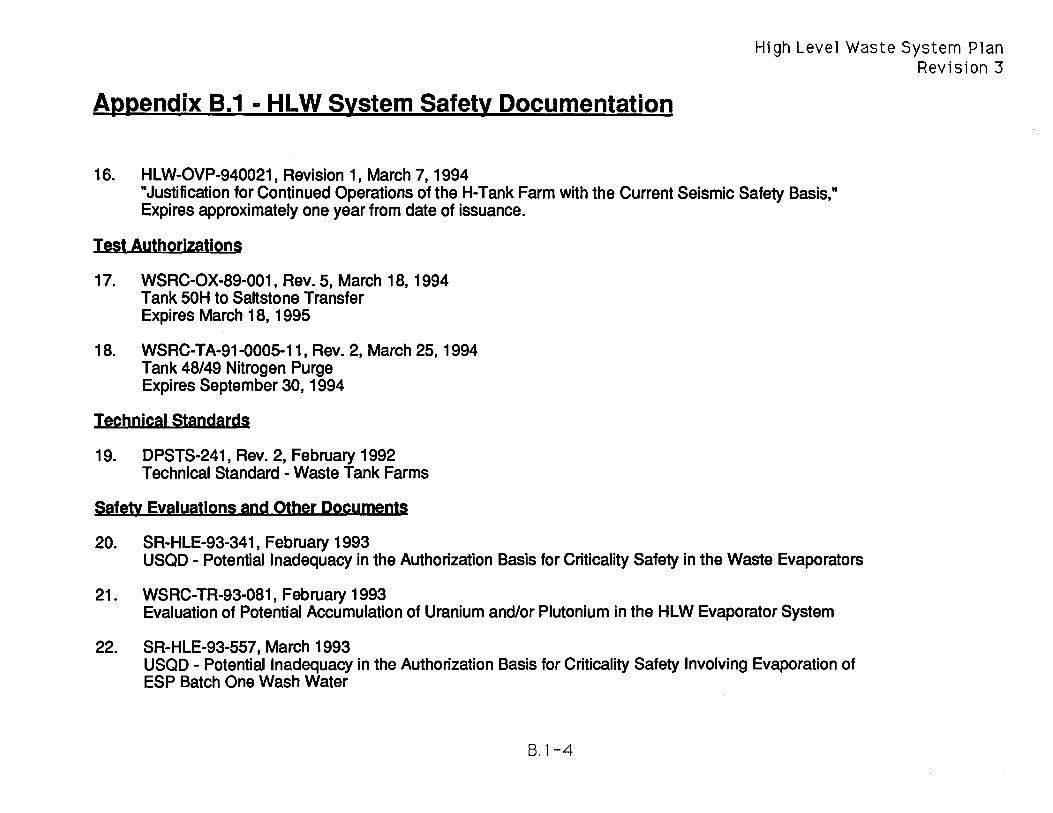
Appendix B.1 - HLW System Safety Documentation
16. HLW-OVP-940021, Revision 1, March 7, 1994
High Level Waste System Plan Revision 3
"Justification for Continued Operations of the H-Tank Farm with the Current Seismic Safety Basis," Expires approximately one year from date of issuance.
Test Authorizations
17. WSRC-OX-89-001, Rev. 5, March 18, 1994 Tank 50H to Saltstone Transfer Expires March 18, 1995
18. WSRC-TA-91-0005-11, Rev. 2, March 25,1994 Tank 48/49 Nitrogen Purge Expires September 30, 1994
Technical Standards
19. DPSTS-241, Rev. 2, February 1992 Technical Standard - Waste Tank Farms
Safety Evaluations and Other Documents
20. SR-HLE-93-341, February 1993 USQD - Potential Inadequacy in the Authorization Basis for Criticality Safety in the Waste Evaporators
21. WSRC-TR-93-081, February 1993 Evaluation of Potential Accumulation of Uranium and/or Plutonium in the HLW Evaporator System
22. SR-HLE-93-557, March 1993 USQD - Potential Inadequacy in the Authorization Basis for Criticality Safety Involving Evaporation of ESP Batch One Wash Water
S,1-4

Appendix B.1 - HLW System Safety Documentation
23. WSRC-TR-93-115, February 1993
High Level Waste System Plan Revision 3
Nuclear Safety of Extended Sludge Processing on Tank 42 and 51 Sludge (DWPF Sludge Feed Batch One)
24. SR-HLE-93-1736, September 1993 USQD - Hydrogen Deflagration in HLW Tank 241-F & H
25. WSRC-TR-93-171, March 1993 Nuclear Criticality Safety Bounding Analysis for the In-Tank Precipitation (ITP) Process
26. WSRC-TR-92-427, October 1993 Safety Evaluation of the ITP Filter/Stripper Test Run and Quiet Time Run Using Simulant Solution (U)
27. WSRC-TR-93-207, April 1993 Safety Evaluation of the ESP Sludge Washing Baseline Runs
28. WSRC-TR-93-031, Rev. 1, April 1993 Hazards Assessment Document Effluent Treatment Facility Balance of Plant
29. SRL-NPS-920001, Rev. 1, January 1993 Safety Envelop Evaluation of ETF Alarm Failure Incident
30. PHR 200-H-33, Rev. 2, October 1990 Periodic Process Hazards Review
31. WSRC-RP-92-1396, (Draft) (Upon WSRC Approval) Safety Evaluation for the New Waste Transfer Facility
B.1-5


Hi gh Leve 1 Waste System Pl an Revision 3
Appendix B.2 - HLW System Environmental Documentation
process
F and H Tank Farm
Evaporators
Replacement High Level Waste Evaporator
Sludge Waste Removal
Salt Waste Removal
Extended Sludge Processing
In-Tank Precipitation
Defense Waste Processing Facility
Saltstone
F/H Effluent Treatment Facility
Transfer Facilities (New Waste Transfer Facility, Diversion Boxes, Inter-Area Lines, Pump Pit Facilities)
Consolidated Incineration Facility
Environmental Documents
1,2,5,9,16,17,21,22,23,31,32
1,2,5,9,16,17,21,22,23,31,32
1,2,5,9,25
1,2,5,9,16,17,21,22,23,31,32
1,2,5,9,16,17,21,22,23,31,32
1,2,5,9,16,17,22,31
1,2,5,9,16,18,21,22,31
3,4,6,7,8,10,14,19,21,27,34
3,7,11,14,20,21,28,30,35
1,2,12,13,21,26,33
NVVTF: 1,2,9,21,24
All (nhers: 1,2,5, 7,9,16,17,21,22, 23,31,32
1,6,7,14,15,21,29
Comments
Note: The following list contains the primary environmental documents associated with the High Level Waste System. It is not intended to be an all-inclusive list.
B.2-1

High Level Waste System Plan Revision 3
Appendix B.2 - HLW System Environmental Documentation
National Environmental Policy Act:
1. ERDA-1537 "Final Environmental Impact Statement - Waste Management Operations - Savannah River Plant -Aiken, South Carolina."
2. DOE-EIS-0062 "Final Environmental Impact Statement - Supplement to ERDA-1537 - Waste Management Operations, Savannah River Plant, Aiken, South Carolina - Double Shelled Tanks for Defense High Level Radioactive Waste Storage."
3. DOE-EIS-0082 "Final Environmental Impact Statement - Defense Waste Processing Facility - Savannah River Plant, Aiken, South Carolina"
4. DOE-EA-0179 "Environmental Assessment - Waste Form Selection for SRP High-Level Waste"
Federal Facility Agreement:
5. Savannah River Site Federal Facility Agreement, Administrative Docket Number: 89-05-FF, effective August 16, 1993.
Land Disposal Restriction-Federal Facility Compliance Agreement:
6. Federal Facility Compliance Agreement; Savannah River Site, EPA Docket #91-01-FFR, EPA ID #SC1890 008 989, March 13, 1991.
Resource Conservation and Recovery Act:
7. RCRA Part A Permit #SC1890008989 for Savannah River Plant, June 30, 1987.
8. RCRA Part 8 Permit Application for the Organic Waste Storage Tank, Volume VI, Interim Status. South Carolina Department of Health and Environmental Control Industrial Wastewater Permit
9. Permit #17,424-IW: F/H Area Tank Farms, March 3, 1993.
B.2-2
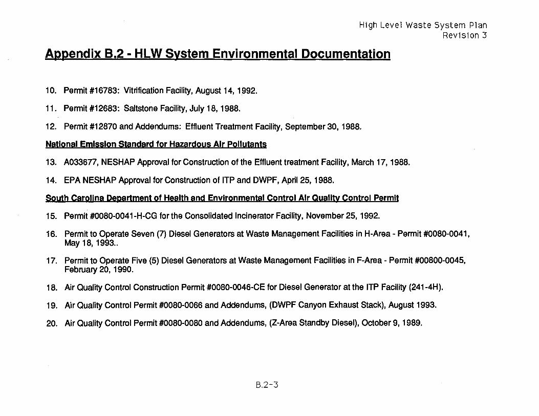
High Level Waste System Plan Revision 3
Appendix B.2 - HLW System Environmental Documentation
10. Permit #16783: Vitrification Facility, August 14, 1992.
11. Permit #12683: Saltstone Facility, July 18, 1988.
12. Permit #12870 and Addendums: Effluent Treatment Facility, September 30, 1988.
National Emission Standard for Hazardous Air Pollutants
13. A033677, NESHAP Approval for Construction of the Effluent treatment Facility, March 17, 1988.
14. EPA N ESHAP Approval for Construction of ITP and DWPF, April 25, 1988.
South Carolina Department of Health and Environmental Control Air Quality Control Permit
15. Permit #0080-0041-H-CG for the Consolidated Incinerator Facility, November 25,1992.
16. Permit to Operate Seven (7) Diesel Generators at Waste Management Facilities in H-Area - Permit #0080-0041, May 18, 1993 ..
17. Permit to Operate Five (5) Diesel Generators at Waste Management Facilities in F-Area - Permit #00800-0045, February 20, 1990.
18. Air Quality Control Construction Permit #0080-0046-CE for Diesel Generator at the ITP Facility (241-4H).
19. Air Quality Control Permit #0080-0066 and Addendums, (DWPF Canyon Exhaust StaCk), August 1993.
20. Air Quality Control Permit #0080-0080 and Addendums, (Z-Area Standby Diesel), October 9, 1989.
6.2-3

High Level Waste System Plan Revision 3
Appendix B.2 - HLW System Environmental Documentation
National Pollution Discharge and Elimination System
21. NPDES Permit for Savannah River Site; Permit # SC000175, September 24, 1986.
South Carolina Department of Health and Environmental Control Domestic Water Permit
22. Permit SC#405556: H-Area Facilities, April21, 1988.
23. Permit SC#405566: F-Area Facilities, May 3, 1988.
24. Permit SC#401118: New Waste Transfer Facility, April 18, 1988.
25. Permit SC#LS91 007: Replacement High Level Waste Evaporator, May 2, 1991.
26. Permit SC#LS-233-W: Effluent Treatment Facility.
27. Permit SC#402186 and Addendums: Defense Waste Processing Facility, Domestic Water Distribution, Tank and Treatment, June 30, 1989.
28. Permit SC#400737: Saltstone, Domestic Water Lines and Tank, May 26, 1988.
29. Permit Pending for CIF.
South Carolina Department of Health and Environmental Control Landfill Permit
30. Saltstone Solid Waste Disposal Site, #IWP-217, approved 10/17/89.
B.2-4

High Level Waste System Plan Revision 3
Appendix B.2 - HLW System Environmental Documentation
South Carolina Department of Health and Environmental Control Sanitary Water Permit
31. Permit #12910 and Addendum: H-Area Facilities.
32. Permit #9326 and Addendum: F-Area Facilities.
33. Permit #9998 and Addendum: Effluent Treatment Facility.
34. Permit #9888 and Addendum: Defense Waste Processing Facility.
35. Permit #13717: Saltstone.
B.2-5


High Level Waste System Plan
Appendix C.1 - Type I, II & IV Tank Waste Removal Schedule Revision 3
[fv I 951 961 97[981 99[001011 021 031 041 051 061 071 081 091 101 111 121 131 141 151 161
Type I Tanks
1 7- ~ ~
2 .. ~
• 3 • ~ ... 4 ~ ., F
• 5
411 Z ...r
6 • ~ .., 7 ~
• 8 ~
., r •
9 ]2 -.& ~
10 ~ b ..,
1 1 ~ 7_ F .. 12 ~ ""'. ... V' start of Sludge" Start of Salt .. Completion of waste • Tank ready
Removal Removal removal, water washing, for waste and annulus cleaning removal
C.l-1
...r
~ r
WI
I
Note 1 - Tanks 2-8 must transfer through Tank 7

High Level Waste System Plan
Appendix C.1 - Type I, II & IV Tank Waste Removal Schedule Revision 3
IFY ]95)961 97r981 99] 02[01\ 021 031 041 051 061 071 081 091 101 111 121 131 141 151 161
Type II Tanks
13 ~ • ~
14 ~ ~7' ~ I
15 ~ .. 16 Complete
i I -- -
[fyU
D7[98 [ggrOoI @ oA63[ 64[05[06I07T281 091 101 111 121 131 141 151 161 171 181
Type IV Tanks (note: only sludge or zeolite heels remain)
I I
17 Complete
18 • '7 .. 19 7' • • 20 Complete
21 ~
7' .. 22
~ "7 -,.
23 • ~ -"'II1II ".
24 • "'0' ... --- ----- -----~
C.1-2

Appendix C.2 - Type III Tank Waste Removal Schedule High Level Waste System Plan
Revision 3
[FvTIsl 961 971981 99r 00101[02[031 041 osl 06[071 08[ 091 101 1 11 121 131 141 lsi 161 171 181
Type III Salt Tanks
2S .,. • F
27 }2 • 28 ... .. I
• 29 ., ., ~
<41
30 f: .. 31 ~ V ...
<41
36 .~ ~
37 ., .. V F
38 , ., .,. <41
41 ~ 12 • 44 ~ ~
4S .. F -46 ,. "WI
• 47 • V' ..
C.2-1
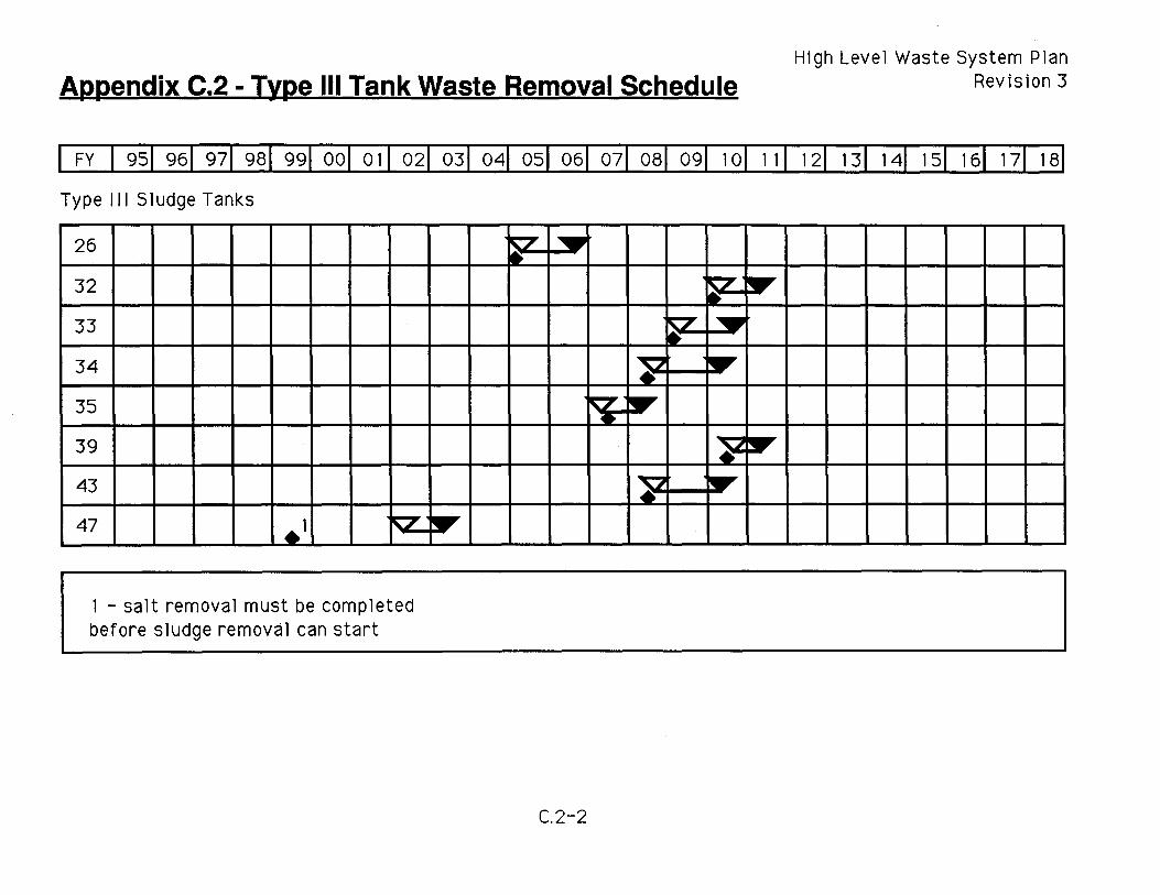
Appendix C.2 - Type III Tank Waste Removal Schedule High Level Waste System Plan
Revision 3
I FY I 951 961 <:riIT8199[oO[OJI 021 031 041 051 061 071 081 091 101 111 121 131 141 151 161 171 181
Type III Sludge Tanks
I
26
32
33
34
35
39
43
47 .1 ~
1 - salt removal must be completed before sludge removal can start
~ ~ ~ .-
tr --&...
C.2-2
~ F • ~ ~ ~
~ ~ ~ .. ~
~ ~
l' .. .&.....-..
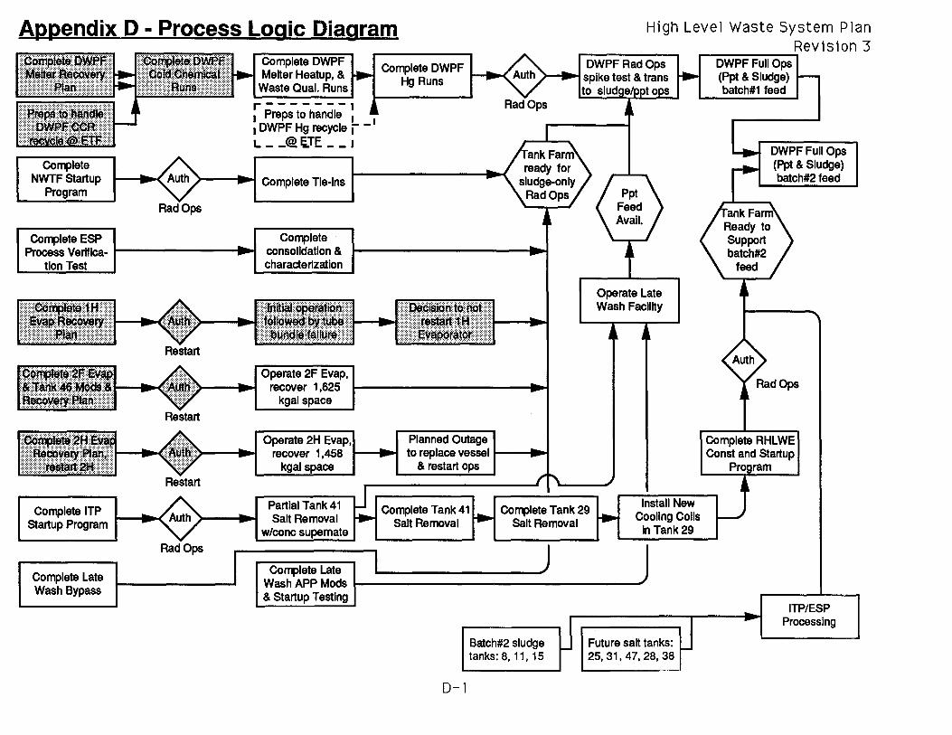
Appendix D - Process Logic Diagram High Level Waste System Plan
Complete ReviSion 3 .---------.;"
Complete NWTF Startup
Complete ESP
Melter Heatup, & Waste Qual. Runs r-------I I Preps to handle I I I DWPF Hg recycle j" -L __ @ s.TE __ J
} ... I Complete Tie-Ins
Complete DWPF ..--....<: Hg Runs
Process Verifica- I ... I Complete
consolidation & characterization
Complete ITP Startup Program
Complete Late Wash Bypass
Restart
Operate 2H Evap, Planned Outage
Operate Late Wash Facility
tit:::} ... I recover 1,458 I .... 1 to replace vessell .... I
RadOps
Partial Tank 41 Salt Removal
w/conc
Complete Late l
& restart
Complete Tank 41 Salt Removal
Complete Tank 29 Salt Removal
j
Install New Cooling Colis
in Tank 29
W~hA~~~1 ' & Startup Testing
D-1
Batch#2 sludge tanks: 8, 11, 15
Future salt tanks: 25,31,47,28,38
DWPF Full Ops (Ppt & Sludge) batch#1 feed
DWPFFuliOps (PPt & Sludge) batch#2 feed
Complete RHLWE Const and Startup
ITP/ESP Processing


High Level Waste System Plan Revision 3
Appendix E - Process Logic Interactive Matrix
process Limber Solution DegeodeOl UDQD
1. Sludge Waste Removal 1. $, time and manpower to 1. Fund projects to implement in 1. Budget erect steelwork, pumps, etc. a timely manner 2. Manpower
2. Manpower available/qualified 2. Ensure ESP space by 3. ESP Operation 3. Chemistry Appropriate for running DWPF 4. DWPF Operation
ESP Blending 3. Effective WR schedule to 5. Transfer Facilities Operation 4. Transfer route available avoid transfer conflicts 6. SRTC Analytical Operations 5. ESP Processing available 4. Timely Analytical Results 7. Space Gain through ITP
(AI Dissolution or not) Operation 6. ESP rate of processing 7. Evaporator capacity 8. Analytical lab support
capacity
2. Sab Waste Removal 1. $, time and manpower to 1. Fund projects to implement in 1. Budget erect steelwork, pumps, etc. a timely manner 2. Manpower
2. Manpower available/qualified 2. Timely Analytical Results 3. ITP Operation 3. Chemistry Appropriate for 3. Run ITP at maximum rate 4. LW Operation
ITP Blending 4. Run LWand DWPF at a rate 5. DWPF Operation 4. Transfer route available equal or greater than ITP 6. Saltstone Operations 5. ITP Processing available 5. Run Saltstone as needed 7. Transfer Facilities Operation 6. ITP rate of processing 6. Effective WR schedule to 8. SRTC Analytical Operations 7. Tank 49 not full avoid transfer conflicts 8. Saltstone availability 9. Analytical lab support
capacity
3. Evaporation 1. Available Salt Receipt Space 1. Funding to support timely salt 1. Startup and operation of ITP 2. Availability/Utility of removal from salt receipt 2. Available manpower.
Evaporators tanks. 3. No major upset scenarios in 3. Timely WM EIS ROD 2. Run ITP to remove salt or Tank Farms/Canyons that
concentrated supernate from would consume ETF capacity Evaporator salt receipt tanks 4. ETF capable of handling
3. Operate evaporators at evaporator overheads planned space gain 5. Efficient completion of NEPA
4. Maintain adequate capacity process in the ETF
E-l
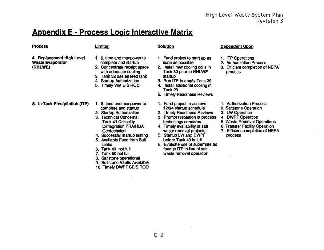
High Level Waste System Plan Revision 3
Appendix E - Process Logic Interactive Matrix
process
4. Replacement High Level Waste Evaporator (RHLWE)
5. In-Tank Precipitation (ITP)
L1mUer
1. $, time and manpower to complete and startup
2. Concentrate receipt space with adequate cooling
3. Tank 32 use as feed tank 4. Startup Authorization 5. Timely WM EIS ROD
1. $, time and manpower to complete and startup
2. Startup Authorization 3. Technical Concerns:
Tank 41 Criticality Deflagration PRAlHDA Geotechnical
4. Successful startup testing 5. Available Feed from Salt
Tanks 6. Tank 49 not full 7. Tank 50 not full 8. Saltstone operational 9. Saltstone Vaults Available 10. Timely DWPF SEIS ROD
Solution
1. Fund project to start up as soon as possible
2. Install new cooling coilS in Tank 30 prior to RHLWE startup
3. Run ITP to empty Tank 29 4. Install additional cooling in
Tank 29 5. Timely Readiness Reviews
1. Fund project to achieve 12/94 startup schedule
2. Timely Readiness Reviews 3. Prompt resolution of process
technology concems 4. Timely availability of salt
waste removal projects 5. Startup LWand DWPF
before Tank 49 is full 6. Evaluate use of supernate as
feed to ITP in lieu of salt waste removal operation
E-2
pependent Upon
1. ITP Operations 2. Authorization Process 3. Efficient completion of NEPA
process
1. Authorization Process 2. Saltstone Operation 3. LW Operation 4. DWPF Operation 5. Waste Removal Operations 6. Transfer Facility Operation 7. Efficient completion of NEPA
process

High Level Waste System Plan Revision 3
Appendix E - Process Logic Interactive Matrix
process
6. Extended Sludge Processing (ESP)
7. Late Wash (LW)
LImiter
1. Manpower to support startup 2. Slurry pump seal leakage
and completion of PVT 3. Available Feed from Sludge
Tanks 4. Evaporator System capacity
to handle wash water transfers, evaporation and salt content
5. Processing space available in ESP Tanks
6. Processing cycles as required to meet DWPF feed acceptance criteria
7. DWPF capable of receiving sludge
8. Timely DWPF SEIS ROD
1. Fund and implement in a timely manner
2. Startup Authorization 3. Technical Concerns
Filter Operation Benzene Stripping
4. Tank 22 available for recycle of wash water
5. DWPF on line 6. Feed available from Tank 49 7. Timely DWPF SEIS ROD
Solution
1. Timely completion of the PVT with slurry pump seal leakage resolution and action plan
2. Timely availability of sludge waste removal projects
3. Maintain Evaporators on line 4. Complete Batch #1 and feed
to DWPF 5. Prompt resolution of process
technology concerns 6. Use of Tanks 21 and 24 to
receive and store wash water for later use
1. Fund projects to implement in a timely manner
2. Prompt resolution of process technology concerns
3. Timely Readiness Reviews 4. Run ITP to supply feed to
Tank 49 5. Run ITP to maintain level in
Tank 22 6. Run DWPF to accept Feed
E-3
Pependem Upon
1. Authorization process 2. Management of personnel
resources 3. Waste Removal Operations 4. Evaporation Operations 5. DWPF Operations 6. Transfer Facility Operation 7. Space Gain through ITP
Operation 8. Efficient completion of NEPA
process
1. Budget 2. Permitting Action 3. Authorization process 4. ITP Operation 5. DWPF Operation 6. Transfer Facility Operation 7. Saltstone Operation 8. Efficient completion of NEPA
process

High Level Waste System Plan Revision 3
Appendix E - Process Logic Interactive Matrix
process L1mUer Solution Degendem UggO 8. Defense Waste Processing 1. Startup Authorization 1. Timely Readiness Reviews 1. Budget
Facility (DWPF) 2. Successful Cold Chemical 2. Prompt resolution of process 2. Permitting Action Runs technology concems 3. Authorization process
3. Technical Concerns 3. Run ESP 4. ESP Operation Ammonium Nitrate Formation 4. Run LW from Tank 49 Feed 5. LW Operation Organic Fouling 5. Run ITP 6. ITP Operation
4. Availability of sludge feed 6. Maintain and increase 7. Evaporator Operation 5. Availability of precipitate feed Evaporator capacity including the RHLWE 6. Tank Farm capable of 7. Implement CIF project 8. Transfer Facility Operation
handling the recycle water 8. Timely completion of waste 9. CIF Operation 7. Benzene appropriately stored removal projects 10. Efficient completion of NEPA
or incinerated process 8. Timely DWPF SEIS ROD
9. Saltstone 1. Feed available from Tank 50 1. Run ITP and ETF 1. Budget 2. Single shift operation 2. Man two shift operation if 2. ITP Operation 3. Vaults must be available required 3. ETF Operation 4. Timely DWPF SEIS ROD 3. Timely funding and 4. Efficient completion of NEPA
construction of new vaults process
10. F/H Effluent Treatment 1. Feeds must meet acceptance 1. Maintain controls on 1. Evaporator Operations Facility (ETF) criteria generators for feed 2. Canyon Evaporator
2. Operational utility 2. Implement utility Operations 3. Tank 50 not full improvements as required 3. Saltstone Operation 4. Ready to receive DWPF 3. Run Saltstone 4. DHEC change approval.
CCR Recycle 4. Complete unloading piping. 5. Efficient completion of NEPA 5. Timely WM EIS ROD process
E-4

High Level Waste System Plan Revision 3
Appendix E - Process Logic Interactive Matrix
process
11. Transfer Facilities New Waste Transfer Facility
(NWTF) Diversion Boxes Inter Area Lines Pump Ph Facllhles, etc.
12. Consolidated Incinerator Facility (elF)
Limiter
1. Jumper changes required 2. Weather can extend
maintenance duration 3. Umited nuni>er of transfer
routes available 4. Operational utility 5. Timely WM EIS ROD
1. $, time and manpower to complete and startup
2. Permitting Process 3. Startup Authorization 4. Provide for secondary waste
treatment or disposal 5. Timely DWPF SEIS ROD
Solytlon
1. Support projects as practical to enclose high traffic diversion boxes
2. Effective scheduling of waste transfers
3. Implement utility improvements as required
1. Fund project to implement in a timely manner
2. Timely Readiness Reviews 3. Implement elF operation
before Benzene Storage at DWPFisfull
E-5
Dependent Upon
1. Weather 2. Budget 3. Efficient completion of NEPA
process
1. Budget 2. DWPF 3. Mixed Wastel Hazardous
Waste Facility (Also new project)
4. Efficient completion of NEPA process

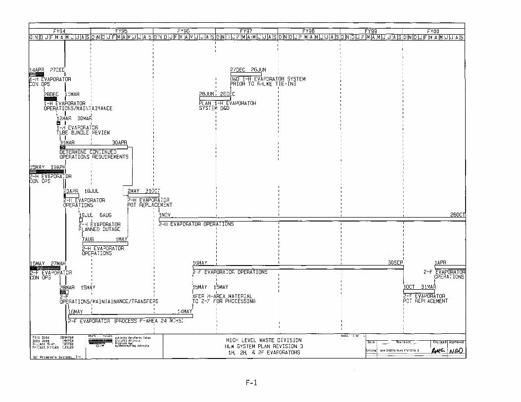
FY94 I FY95 I FY96 I FY97 I FY98 I FY99 I FYOO olNIDIJIFIMIA MIJIJIA SlolNIDIJIFIMIAIM JIJIAISlolN DIJIFIMIAIMIJIJIAISIOINIDIJIFIMIAIMIJIJIAISlolNIDIJIFIMIAIMIJIJIAISlolNIDIJIF MIAIMIJIJIAISlolNIDIJIFIMIAIMIJIJIAIS
I I I I I I I I I I I I
14APR 27DEC 27DEC 26JUN I
~VAPoRATloR I I I
D&D 1-H EVAPORATOR SYSTEM ON DrS I PRIOR TO RHLWE TIE-INS
26D~C 28DEC 11MAR 28JUN - I I I 1-H EVAPORATOR PLAN 1-H EVAPORATOR OPERATIONS/MAIN AINANCE SYSTEM D&D
I I ; I
12MAR 30MAR I
II I I I I I i-H EVAPORATOR I
TUBE BUNDLE REVIEW I
I I I I
I I 3iMAR I 30APR I Iii! I-DETERMINE CONTINUED OPERATIONS REQUIREMENTS I
I I I I i5MAY i9APR I I
I I I
2-H EVAPORATOR I I
l>oN oPS 11 I I I
IiMAY I
I 310CT 20APR i8JUL
m::::=:J I
2-H EVAPORATOR 2-H EVAPORATOR OPERATIONS POT REPLACEMENT
I I I I
i9JUL 6AUG iNoV 280CT 0 I I 2-H EVAPORATOR 2-H EVAPORATOR OPERATIONS PLANNED OUTAGE I
I I I I
7AUG iMAY I
I I I
2-H EVAPORATOR I
oPE~ATIoNS I I
I i6MAY I 30SEP 1APR i5MAY 27MAR I I
I I I
I I 2-F EVAPORATOR I 2-F EVAPORATOR OPERATIONS I 2-F EVAPORATOR ~oN OPS II
I
J I OPERATIONS
I I
3iMA~ I I
28MAR i5MAY i5MAY i5MAY lOCT Ell] I I I I I 2-F I XFER H-AREA MATERIAL 2-F EVAPORATOR oPERATIoNS/MAINTAINANCE/TRANSFERS TO 2-F FOR PROCESSING POT REPLACEMENT I' I
i4MAJ I I
I I I I i6MAY I , I I
I I I I
2-F EVAPORATOR (PROCESS F-AREA 24 MTHS) I I
I I I I
I I I I I
Plot Date 26MAY94 start InlSI1 Sheet 10f I I Activity Bar/Early Dales HIGH LEVEL WASTE DIVISION Data Date lMAY94 Critical Activity Date Revision Checked A roved Project Start 10CT90 i Progress Bar
Project Finish 1JUL20 0/1" Milestone/Flag Activity HLW SYSTEM PLAN REVISION 3 /25/941 HLW SYSTEM PLAN REVISION 3 144lc:.. I N (b() iH, 2H. & 2F EVAPORATORS
{c] Primavera Systems, Inc.
F-l
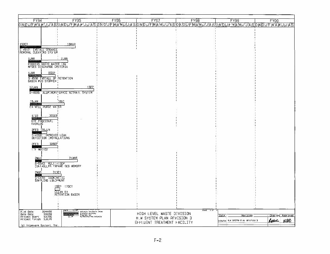
FY94 FY95 FY96 FY97 FY98 ~99 FYOO O\N\D\J\F\M\AlM\J\J\A\SiO\N\D\J\F\M\A\M\J\J\A\SiO\N\D\J\F\M\A\M\J\J\A\S!O\N\D\J\F\M\A\M\J\J\A\SiO\N\D\J\F\M\A\M\J\J\A\S\O\N\D\J\F\M\A\M\J\JJJC[SiO\NiDiJiFiMiAiMiJiJiAis
150CT 16MAR
S-~512: INSTALL ORGANIC REMOVAL CLEANING SYSTEM
1JAN I , 2JAN ------, PROCESS WASTE WATER lAW NPDES DISCHARGE CRITERIA
1JAN I BSEP: 'S-i~15~3'6~ItN~S;TA~L~L~B~~ 'RETENTION BASIN MUD STOPPER;
12JAN I :
1
1SEP ---, S ~B95: ALUMINUM/FERRIC NITRATE SYSTEM
15JAN I :1DEC I
ER WELL PURGE WATER
1FEB I 30SEp: I
ETF PROCEDURE I
BACKLOG '
2FEB '20JUN iii~t=~1 , S ~350: IMPROVED LEAK DETECTION INSTALLATIONS
2FEB I 30SEP; I
ETF WAD (S) ,
I 2MAR 31MAR -----, S-55~3: MULTI-LOOP CONTROLLER EXPAND OCS MEMORY
I ; 2MAR 310CT
I S-O~30: ISOKINETIC SAMPLING EQUIPMENT ,
1SEP 170CT D CLEAN BH RE,TENTION BASIN
Plot Date 26MAY94 Data Date lMAY94 Project Start 1DCT90 Project Finish lJUL20
Ie) Primavera Systems. Inc.
~niS··iActivitY8ar/EarIYDates I Crlt1calActlvHy
c::=:J Progress Bar 0/" Milestone/Flag ActIVitY
HIGH LEVEL WASTE DIVISION HLW SYSTEM PLAN REVISION 3
EFFLUENT TREATMENT FACILITY
F-2
Sheet jot
Date Revision Checked I Aooroved
126/941 HLW SYSTEM PLAN REVISION 3 I~I fJpA)

FY94 FY95 J_ ~~6 __ I FY97 FY98 FY99 1 FYOO p1N 10 IJ IF'TfllAjM IJ IJ IA]SIO IN 10 IJ IF 1M IA 1M IJ IJ IA Is 10 IN 10 IJ IF 1M IA 1M IJ IJ IA Is 10 IN 10 IJ IF 1M IAJM IJ IJ IA 1510 IN 10 lJfJM IA 1M IJ IJ IA Is [0 IN 10 IJ IF 1M IA 1M IJ IJ IA Is 10 IN 10 IJ IF 1M IA 1M IJ IJ IA Is
10CT 22SEP
, , 100CT O. ODE AUTHORIZATION FOR OUTAGE/HOT TIE-INS
26FEB 23FEB <> , PRECIPITATE FEED AVAILABLE FOR OWPF ,
21OEC' '100CT ;:>'i.IA~ ¢--J' , C:=:::J
[IP STARTuP/TESTING ~AUTHOFiIZATION FOR ITP :SALT R<: ,,4n1l A' I CHEMICAL ADDITION T~NK 4B ,CYCLE = '~n\ lBAPR 2BJUL : :110CT 3MAR 22MAR 19AUG: 21FEB BJUN 2FEB 19M~ -===::J I I I , I I ,{:~~~ ,C:=:::J C:=:::J M I' I READINESS SELF , :SALT REMOVAL CYCLE 3 ITP PRODUCTION SALT REMOVAL' SALT REMOVAL ASSESSMENT I J ' , (41,29, 3B, 27, 2B SS) CYCLE 6 1 ' CYCLE B (31, 25) CYCLE 10 (25, 3B)
11 I :, r : r . 29JUL 3SEP' , 160CT 20AUG 22SEP 2BJUL 12NOV
c=J I' ,0, I C:=:::J I WSRC , ITP PRODUCTION ITP MAINTENANCE SAL T REMOVAL ORR , CYCLE 5 I OUTAGE I CYCLE 9 (31, 25)
J 26SEP 210 T r5FEB 25AUG1
, 12MAY 90b ~3SEP 20~EB 3AUG: 310EC I ~
Plot Date 26MAY9~ Data Date IMAY9~ Project Start IDCT90 Project Finish IJUL20
ODE SAL T REMOVAL CYCLE 2 ITP PROOUCTI ON CYCLE ITP PROOUCTI ON SALT REMOVAL! ORR (41, 29, 32 SALT ISS) 4 (STO 3 BATCH) l CYCLE 9 1 I CYCLE 11 (3B) 1 1;1 t t : ' ~ I
15AUG 310EC 2MAR 100CT 12APR l1MAY 16MAR lJUL ' 27JU: lJAN 7FEB I II 01 ' C:=:::J' , 01 4B,3B SUPERNATE TRANSFER ITP PRODUCTION ITP MAINTENANCE SALT REMOVAL: ITP PRODUCTION ITP MAINTENANCE FOR BATCH 1, CYCLE 1 CYCLE 2 (5 BATCHES) OUT AGE' CYCLE 6 (25) , CYCLE B OUT AGE I
lJANI
24FEB : 170CT llAPJ I ~2JAN ~FIEB 7JUL,
ITP PRODUCTION : ITP PRODUCTION CYCLE SAL T REMOVAL CYCLE 1 (4 BATCHES) ,3 (4 BATCHESl CYCLE 7 (31) .--J! ! I
10CT L 20JAN 6MAY 21AUG I I C:=:::J ' SALT REMOVAL CYCLE 1 ' SALT REMOVAL (4B, 3B, 41, 49, 32 SALT ISS) CYCLE 4 (29) ~~nnnJ' , ~ 90EC :
; OUT AGE/HOT : , TIE-INS
start hmS i ~~Ur~~I ~~~{;~~~y Dates
Sheet 10f
__ -===:J Progress Bar 0/" Mllestone/Flag Activity Date Revision HIGH LEVEL WASTE DIVISION
HLW SYSTEM PLAN REVISION 3 IN-TANK PRECIPITATION ~/26/941 HLW SYSTEM PLAN REVISION 3
Chec-kedl Aooroved
~INfUJ (c) Primavera Systems, Inc.
F-3

FY94 FY95 FY96 FY97 FY98 FY99 ~ FYOO OINIOIJIFIMIAjMIJIJIAISIOINIOIJIFIMIAIMIJIJIAISIOINIOIJIFIMIAIMIJIJIAISIOINIOIJIFIMIAIMIJIJIAISIOINIOIJIFIMIAIMIJIJIAISIOINIO]yOFIMIAIMIJIJIAISIOINIOIJIFIMIAIMIJIJIAis
~UL 19NOV I I
ANK 51 CYCLE 1 WASHING: SUSPENSION TESTING I
t:>JUL
4FEB 111JUL I I
1,,,,,,:i1l I
PUMP TESTING :
I i150CT
21DEC 20DEC <>----, , ESP - AUTH RESTART/RESUME BATCH 1 PROCESS I
21DEC 20MAR
~COMPLdTE BATCH 1 , WASHING (IF REQ'D)
! I
21MAR 19APR: 0---, , TRANSFER TANK 42 SLUDGE TO TANK 51 & BLEND
I I I
20APR
I 27DEC 29JANI rl~~~:;;::;;:;;;::;:;:~d
I BATCH 2 SLUDGE WASHING (TANK 40) (13 MTHS)
: j J7D~C I ~ , MODIFIED SAR APPROVEDI [OR "IjSITEO WATER FLO'
3DAPR I 12NOV 26DEC I I I r::::J---J
ESP - PROCESS I I; I TANK 42 SUPPORT ITP/ESP/TF EMERGENCY SPACE I TRANSFER WASTE (BF) TOI IvERIFICATION ~ESTI~G : I' : TANK 40 & SETTLE/DECANT
12JUL 14JUL 30DEC 310CT h II I XFER TANK 51 CYCLE 1 WASH TO DWPF TANK 51 - 70 MTHS) TO TANK 43 & OTHER TKS ' I
15JUL 17 JUL 17 JUL 16MA Y 29JUN I I I; II : , r;i I II I I I 'XFER TANK 42 CYCLE ESP COMPLETE BATCH TRANSFER WASTE (15H) TO
1 WASH TO TANK 51 #1 CHARACTERIZATION TANK 42 & SETTLE/DECANT ! I I; I I I I I I 1BJUL 150CT 1APR 31MAR : 30JUN ~ 27SEP
¢ , c::::==:J I TANK 42 TANK 21 VALVE BOX COMPLETE ALUMINUM DISSOLUTION CYCLE 2 WASH / TK21 AVAIL PVT WASH BATCH 2 (TANK 42)
I n' ~ I I I 16APR 17 JUN 30SEP 290EC 2BSEP 11NOV I::J I I I c:::::J----l D TANK 42 I TK 51 - TTP INSTALLATION TRANSFER WASTE (11H) TO CYCLE 1 WASH & HOT TIE-IN TANK 42 & SETTLE/DECANT
~ .J ",,; J I I I I ~50CT ~ 9FEB
TANK 51 ALUMINUM DISSOLUTION CYCLE 2 WASH BATCH 2 (TANK 42)
Plot Date 26MAY94 Data Date IMAY94 Project Start IOCT90 Project Finish IJUL20
I 30SEP <>----, TANK 40 VALVE
~~OX COMPLETE
1DCT .r--
I 30SEP
TANK 40 SUPPORT I
ITP/ESP/TF EMERGENCY SPACE I
~iS"IA[;tiVitY8ar/EarIyDates Criti!:al ActlVIty
______ c:::=J Progress Bar 0/" Mllestone/Flag A!:tivity
(c) Primavera Systems, Inc.
HIGH LEVEL WASTE DIVISION HLW SYSTEM PLAN REVISION 3 EXTENDED SLUDGE PROCESSING
F-4
Sheet 10f
Date Revision
! 10FEB 3JUN
I BATCH 2 SLUDGE WASHING (TANK 42) (16 MTHS)
I
Checked I Approved
/26/941 HLW SYSTEM PLAN REVISION 3 ~ INIW

FY94 FY95 FY96 FY97 I FY9B FY99 1 FYOO OINIDIJIFIMIA~MIJIJIAISloINIDIJIFIMIAIMIJIJIAIS\o!N!D!J!F!MIA!M!J!J!A!S\o!N!D!J!F!M!A!M!J!J!A!S\o!N!D!J!F!M!A!MIJ!J!A!Slo!NIDIJ!F!MIA!MIJIJ!Als\oINID!JIF~IJJJ1AlS
lOCT 21FEB
~oMPLETE CONSTRUCTION
lOCT I i ~DBB STARTUP/TESTING:
I
26MAY o
DW3000 c::::rr:::::::: SPIKE TEST/T RANS-RAD oPS
INTEGRATED SYSTEMS COMPLETE
26MAY
~EP i14SEP DOE APPROVAL FOR LINE TIE-INS ~C[ I t6EP 9NoV LINE I TIE-INS
I I 10NoV 19NoV o I POST LINE TIE-INS TESTING I I
22SEP l6JUN 20NoV 29NoV D-h
Plot Date 26MAY94 Data Oate lMAY94 Project Start 10CT90 Pro j ect Fin ish lJUL20
READINESS SELF ASSESSMENT
DOE REVIEW POST TIE - IN TESTING
~OV KD #4 APPROVAL TO I
COMMENCE OPERATIONS "--Tl i±j,
Lj.2!oV HDBB OPERATIONS
l7JUN I 17LG~ DW300 c=J I L...C:::JI::::: WSRC I BEGIN ORR 1: RAD OPS
lBAUG l4SEP D-f-l DOE ORR
I
l3JUL l2JU~COnO~025 Of-, I
MOBILIZE XFER H-AREA CONSTRUCTION MATERIAL TO
Cl~~y~ l4SEP EXCAVATE LINES
I start fInISh I ~~UrgI ~~~{~i~~Y Dates
] Progress Bar 0/" Milestone/Flag Activity c::::x:J ConnectingACtivityonSheatx
HIGH LEVEL WASTE DIVISION HLW SYSTEM PLAN REVISION 3
NEW WASTE TRANSFER FACILITY (c) Pr imavera Systems, Inc.
F-5
26JUN
Sheet lot
Date) Revision Checked) Approved
15/26/941 HLW SYSTEM PLAN REVISION 3 14tt~ I ",(I,,{)
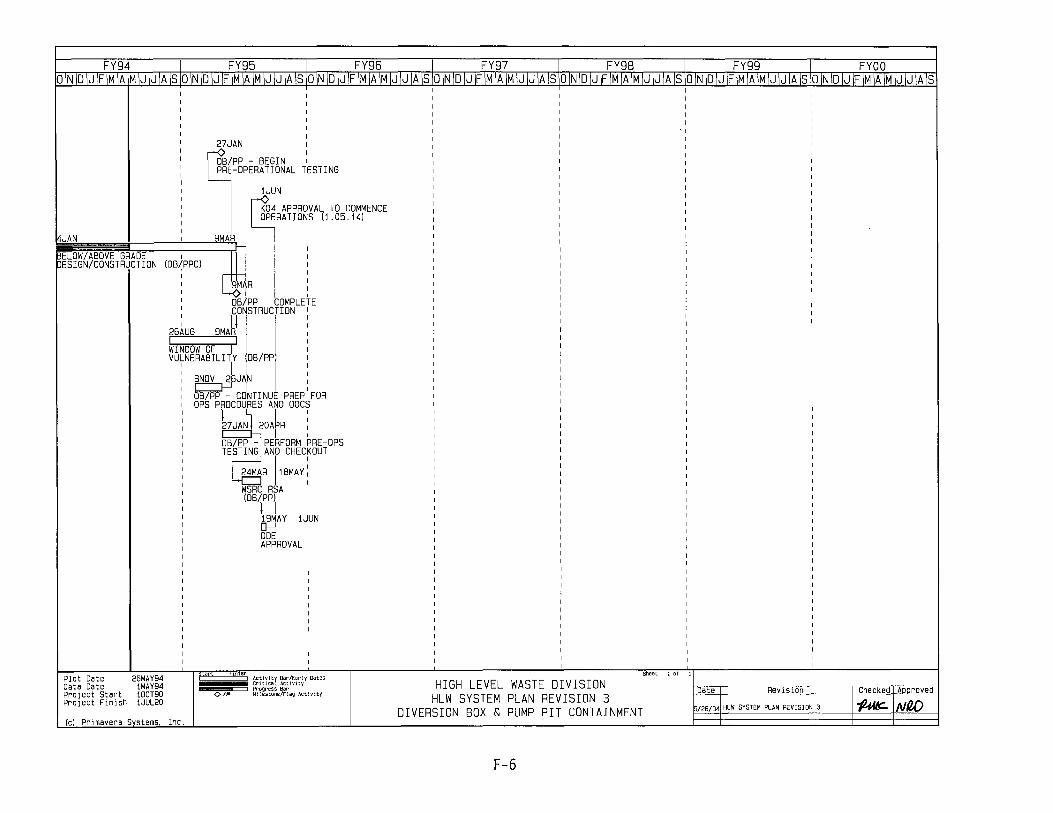
FY94 FY95 FY96 FY97 -------r FY98 FY99 1 FYOO O\N\D\J\F\M\AjM\J\J\A\SIO\N\D\J\F\M\A\M\J\J\A\SIO\N\D\J\F\M\A\M\J\J\A\SiO\N\D\J\F\M\A\M\J\J\A\SIO\N\D\J\F\M\A\M\J\J\A\SiO\N\D\J\F\M\A\M\J\J\A\SiO\N\D\J\F\M\A]M\J\J\A]S
27JAN I
OB/PP - BEGIN I PRE-OPERATIONAL TESTING
I
1JUN I
K04 APPROVAL TO COMMENCE OPERATIONS (1.05.14)
I
JAN 9MA8 l : I ELOW/ABOVE GRADE I I
ESIGN/CONSTR~CTION (OB(PPC) :
9MAR :
OB)PP - COMPLETE CONSTRUCTION I
Plot Date 26MAY94 Data Date IMAY94 Pro j ect Start IDCT90 Project Finish IJUL20
I I) 26AUG 9MAR I I WINDOW OF I VULNERABILITY OB/PP
BNOV 2~JA.N c::=J---J I I
OB/PP - CONTINUE PREP FOR OPS PROCOURES AND DOCS
}7JANJ.20A~R : I I
OB/PP - PERFORM PRE-OPS TESTING AND CHECKOUT
~R 11BMAY! WSRC RSA (OB/PP)
l \ , 19MAY 1JUN [}---J DOE APPROVAL
~fSfl'ActivitY8ar/EarlYDates CritIcal ActIVIty
___ m:::::::::::l Progress8ar 0/" Milestone/Flag ActjVlty
(c) Primavera Systems, Inc.
HIGH LEVEL WASTE DIVISION HLW SYSTEM PLAN REVISION 3
DIVERSION BOX & PUMP PIT CONTAINMENT
F-6
Sheet lot
Oafe-r Revision CheckedJAIllJroved
15/26/941 HLW SYSTEM PLAN REVISION 3 "'/441!:- I NW

FY94 FY95 FY96 FY97 I _ FY98 FY99 FYOO OINIDIJIFIMIAIMIJIJIAISiOINIDIJIFIMIAIMIJIJIAISiOINID\J\F\M\A\M\JIJ\A\SiO\N\DIJ\F\M\A\M\J\J\AISiO\N\D\J\FIMIAIMTJIJIAISIOJNO[O:OFIMIA\M\J\J\A\SIO\N\D\J\F\M\AIMIJIJIA\S
lOCT
30APR , , CONSTRUCTION COMPLETE (MECHANICAL)
30APR
27JUN : <>-----, , DOE APPROVAL FOR LINE TIE-INS
~UN i7AUG RHLWE HOT TIE- INS
) ~ BAUG lSEP 0' WSRC ORR PART II
) ~ 2SEP 24SEP D'
ITLE III DESIGNTCONSTRUCTIoN RHLWE
:90CT 1 lAUG
DOE ORE PART II
Plot Date 26MAY94 Data Date IMAY94 Project Start IOCT90
,! rl ,RHL WASTE EVAPORATOR , ,FUNCTIONAL STARTUP/TESTING
I \ ' [jlOAPR llNoV,
READINESS SELF ASSESSMENT PART I
lMAY
~L,n :~V 130EC , WSRC ORR
PART I
~DEC 26JUN ODE ORE tPART I
1 CONSTRUCTION - COMPLETE PUNCHLIST ,
160EC 2JUN
WSRC RESOLVE ORE CoMMENTS/PUNCHLIST
,start finis. ~~nr~~I ~~~{~~~~y Dates
I Progress8ar 0/" Milestone/Flag At:tivity
)' 25SEP 5NOV o HOT RUNS TESTING , ) : 6NoV l4NOV
[]--, : ESAAB , REVIEW
:~V KO #4 APPROVAL TO COMMENCE OPERATIONS
~V REPLACEMENT HL WASTE EVAPORATOR OPERATIONS
2BJUL
LJ f6JAN 17NoV J INSTALL COOLING , COILS IN TANK 29
Sheet 10f
Date Revision
-,-----2BSEPI
Checkedl Approved
Pro j ect Fin ish IJUL20
HIGH LEVEL WASTE DIVISION HLW SYSTEM PLAN REVISION 3 REPLACEMENT HLW EVAPORATOR 15/26/941 HLW SYSTEM PLAN REVISION 3 I~(!:.I ",fd)
(c) Pr imavera ~tems, Inc.
F-7

DESIGN/PROCUREMI
I I I
10CT
FY96 FY97 FY9B FY99 FYOO A IS lOIN I D I J IF I M I A 1M I J I J I A I SID IN I D I J IF I M I A I M I J I J I A I SiD IN I D I J IF I MlAlMTJ I J I ill 10 I N I D IJlF I M I A 1M rJTJTATSIO IN 10 I J I F I M-IATM IJ I J illlS
Jh,"" 1JUN 30JUL ::~::~~~~====~~~~I-------c=:J I :NT/CONSTRUCTION START SLURRYING TANK
29 TO SUPPORT TRANSFER
1 r BJAN I
1MAY 21AUG c::== TANK 3B
! I
3JAN 2JAN o INSTALL ISOLATION VALVE
BETWEEN TK09 & TK10
2BMAYI
~============~=================~~==~==;==================1~3~O~CTJ-____ ---{3FEB 3APR l<"Of' RETURN TANK 31 TOI
RECEIPT SERVICE
.Jrc.o .JRI"'R
II 15DEC 13NOV 11SEJ
I 10CT 29NOV
-c=J---, OMPLETE TANK 25 CONSTRUCTION -nn ,~NG TANK TANK 2B SALT REMOVAL I L£ART SLURRY INSTALL TANK 31
)n~T TRANSFER CHECKOUT & STARTUP - OPC
I I I 25 TO SUPPOR
10CT I I I COOLING COILS
1BJUL 10CT I I
I TANK 25
II 30SEp: I I 1 I I l7FtBj
ANK 29 SALT REMOVAL CHECKOUT & STARTUP - OPC - I
Plot Date Data Date Project Start PrOject FinIsh
26MAY94 1MAY94 iOCT9D 1JUL2D
lel Primavera Systems. Inc.
I 6SEP 7FEB
T ANk25 SALT REMOVAL CHECKOUT & STARTUP I
OPC
-J I 122At
I 6APR a 22JUN
rrt-··--·--hii-;S'f A"tlvjtyB8r/E"rh~"tes I!iiiiiiiiiiiii crlucelActlvfty -=::l Progress Bar
O/~ Milestone/Flag Actlvlty
TANK 31 TANK ~ SALT REMOVAL TANK 2B I CHECKOUT & STARTUP - OPC I
I I
1MAY 30APR 21AUG 190CT I 5NOV
TANK 3B DESIGN PROCUREMENT START SLURRYING TANK ) ~TA~N~K::;37;=======~=;~ C1M~A~R~;;,::;;;;:::;;;;:~:;;,~:;;;;;;;.~:;;;;;.;;;;;;;;;~;;;:::============~3=B=T~O==S=UP=P=0~;M=TA~:)-R_AN_S_F_ELR~2~2~J':Ju~ES~::~:ROCUREMENT /CONSTRUCTI 0jN
ST ART SLURRY ING TANK 2B TO SUPPORT TRANSFER
I I
Lj~~;;:;::=====~===~====~===============::==17~N=OJV :~~~Gnn _., T nr"_,,,, 30M Y TANK 29
22JlN
11-1.1'4" V;::J >JI-\L I nI:.J"IUVI-\L
CHECKOUT & STARTUP - OPC I
27JUL 12JUN 12JUN I I RETURN TANK ~1 TO TANK RECEIPT SERVICE , )
13FEB 17DEC I 20
TANK 3B SALT REMOVAL TANK 1~ SALT REMOVAL CHECKOUT & STARTUP - OPC J CHECKOUT & STARTUP - OPC I I
I I 1MAY llSE I TANK 31 I
20MAY
RE~~~~I~~N~E~~It~1 l~AUGI
I TANFTIl DESIGN/PROCUREMENT /CONSTRUCTIONI
I
HIGH LEVEL WASTE DIVISION HLW SYSTEM PLAN REVISION 3 WASTE REMOVAL - SALT TANKS
Date I ReVISIon
i/26/JHLWSySTEHPLAliREYISION3
:heckedl Approve
1~{IJj)
F-8

FY94 FY95 FY96 FY97 FY98 FY99 1 FYOO O\N\D\Jf\M\AIM\J\JIAISIOIN\DIJfIMIAIMIJIJIAISIO~IDIJflMIAIMIJIJIA~IOINIDIJfIMIAIMIJIJIA\SIOINIDIJfIMIA\MIJIJIA\S\O\NIDIJfIMIAIMIJIJ\A\SID\N\D\J\F\M\A\~\J\J\A\S
Plot Date 26MAY94 Data Date lMAY94 Proj eet Start 10CT90 Project Finish 1JUL20
(el Primavera Systems, Inc.
10F"O C TAl,,,
start ftnls I Activity Bar/EarlyOates
Critical Activity -==:J Progress Bar 0/" Milestone/Flag ActlVIty
TANK 11 DESIGN/PROCUREMENT/CONSTRUCTION
2JJ II . I
I
SMAY 20EC
TANK 15 SLUDGE REMOVAL CHECKOUT & STARTUP-OPC TANK 08 II , I
6NOV DEC 2JUN 21JUL I
TANK OS- SLUDGE REMOVAL CHECKOUT & ST ARTUP-OPC T A"" 11'
15A~G I' 1JUN~ 30SEP I c=
I
30SEPI
TANK 11 SLUDGE REMOVAL CONS TANK 1S CHECKOUT & STARTUP-OPC SLURRY PUMPS
I I I I 16FES 15FES
~ANK 12 DESIGN/PROCUREMENT/CONSTRUCTION I I' I
3JUN 23JUL 17JAN 310CT I I TANK 15 i
I
13AUG
TANK 12 SLUDGE REM-OVALI CHECKOUT & STARTUP-OPC
13AU(
TANK 04 DESIGN/PROCUREMENT/CONSTRUCTION I I
Sheet 10f
1FES 31JAN
CONS TANK 19 SLURRY PUMPS I
31JAN 31JA
, TANK 05 DESIGN/PROCUREMENT/CONSTRUCTION
I
17FES 3DEC
TANK 04 SLUDGE REMOVAL : CHECKOUT & ST ARTUP-OPCI
HIGH LEVEL WASTE DIVISION HLW SYSTEM PLAN REVISION 3
WASTE REMOVAL - SLUDGE TANKS
-Oate I Revi.:hlon
5/26/9JHLWSYSTENPLANAEVISION3
Checked I Aporoved
J~tvel)
F-9

FY94 FY95 FY96 FY97T FY98 FY99 1 FYOO O\N\D\J\F\M\AIM\J\J\A\SIO\N\D\J\F\M\A\M\J\J\A\SIO\N\D\J\F\M\A\M\J\J\A\S\O\N\D\J\F\M\A\M\J\J\A\SIO\N\D\J\F\M\A\M\J\J\A\SiO\N\D\J\F\M\A\M\J\J\A\SIO\N\D\J\F\M\A\M\J\J\A\S
10CT 30JUN
~ATE WASH FAC DESIGN. ~ROCURE. AND CONSTRUCTION
I lOCT 24JUN
I
UXILIARY PUMP PIT I
Y PASS MODIFICATION I
~
rCT I: 15EP EVISE, REVIEW. AND APPROVE SAR ~
1DCT 1 BAPR I I
I 16NOV
'~F READY
I~,~AD OPS ~V 15DEC
DOE-HQ REVIEW FOR RAD OPS
~EC 29DEC
WSRC CORRECTIVE ACTION - RAD OPS
~N BEGIN RAD OPS
2JAN 1JUN I I
2JUN .--~ELTER OFF-GAS MODS/TSTS/HEATUP SPIKE I MEL TER #1 I MEL TER #2 ~A & PREP-OUTAGE I
II : 19APR 11AUG tc=J ' INITIAL I
MELTER RUNS I ;
TEST/TRANS-RAD OPS REPLACEMENT OUTAGE REPLACEMENT OUTAGE hi: I J I : j
16APR 1JA 2JUN I 1JUN I I I I RADIOACTI~E OPERATIONS RADIOACTIVE OPERATIONS
12AUG 12DEC
Plot Date 27MAY9~ Data Date lMAY9~ Pro j ect Start lDCT93 Project Finish 3DNDVDD
I I _ INSTALL LAlc WA~M H2/,NH3 rODS FACIL~TlY STARTUP
13DEC 17MA Y :
~ASTE QUA1UFICATION RUNS/OUTAGE/PREP-HG OUTAGE
I : I 1BMAY 24AUG c:::::::J ~ I MERCURY TESTING/POST HG.OPS OUTAGE/CORR.EVAL
L~"" I ~ 15NOV I
TRR APPRVL/SELF-ASSESSMENT/WSRC ORR '
I
start flnis I ~~nI~~I ~~~{;~~~y Dates HIGH LEVEL WASTE DIVISION
HLW SYSTEM PLAN REVISION 3 VITRIFICATION - DWPF
_===m:::::::::J Progress Bar <>/~ Milestone/Flag ActiVIty
(c) Primavera ~stems. Inc.
F-IO
Sheet lot
Da-tel Revision Checked 1 Approved
/26/941 HLW SYSTEM PLAN REVISION 3 /2tkc... I rJ fU)

FY94 FY95 FY96 FY97 FY98 FY99 1 FYOO O\N\O\J\F\M\AIM\J\J\A\SIO\N\O\J\F\M\A\M\J\J\A\SIO\N\O[J\F\M\A\M\J\J\A\SiO\N\O\J\F[M\A\M\J\J\A\slo\N\O\J\F\M\A\M\J\J\A\S\O\N\O\J\F\M\A\M\J\J\A\slo\N\O\J\F\M\A\M\J\J\A\S
, ,
~R : 3APR, 1~10CT : SSV #2 PROJECT SSV #1 ROOF PROJECT VA~IDATIO~ ~ALIDATION ~UTHORIZATION:
I I I I I
~~:R #2 3~~~~SE TITLE :~~T #2 PROJECT l I ~P:3 JROJECT II DSGN/FDC/CDR/PMP ~UTHORIZATION ~ ~ VA~IDAT~ON
[}APR : I 30APRJ 'lOCT '30APR 10CT 29SEP SSV #1 ROOF SSV #1 ROOF T-I&II REVISE PMP DSGN/SUBCONTRACT PKG/CNSTRCTN
, . \'
SSV #1 TITLE 1&11 DSGN/SITE PREP/CNSTRCTN/SU
~ , , 3JAN 131MAY 20CT 30SEP 30APR lOCT S~S~V·#·4PIROOF GEN SSV #2 PROCURE/SITE FPR/PMP/TITLE I & II DSGN PREP/CONSTRUCTION/START-UP
SSV #1 PROJECT AUTHORIZA TION
t I I I 1 . I ' ' 1JUN : 20CT 30SEP I I SSV #4 ROOF SUBCONTRACT SSV #3 UPDATE SSV #1 UPDATE PKG/CONSTRUCTION & ISSUE PMP & ISSUE PMP
?JUN ~30~V 1SEP 30SEP' ~T SSV #1 ROOF SSV #3 GEN FPR/FDC/CDR SSV #3 PROJECT NEVISE FPR/CDP & INITIATE PMP , AUTHORIZATION
; Q?CT 30SEP1
Plot Date 26MAY9~ Data Date lMAY9~ Pro j eet Start lDCT90 Pro j eet F in ish lJUL20
start fInIS i Activity Bar/Early Oates
Critical Activity _ c::::::::J Progress Bar o /~ Hi lestone/Flag Activity
Ie) Primavera Systems, Inc.
SSV #3 TITLE I&II ' DSGN/SITE PREP/CNSTRCTN/SU
rSEP 30SEPJ SSV #1 GEN FPR/FDC/CDR & INITIATE PMP :
,
HIGH LEVEL WASTE OIVISION HLW SYSTEM PLAN REVISION 3
Z-AREA SALTSTONE - OWPF
F-l1
Sheet 1 of
Date I Revision
15/26/941 HLW SYSTEM PLAN REVISION 3
CheckBdl Approved
4-k..\AlfU)

FY94 FY95 FY96 FY97 FY98 I . FY99 FYOO O!N!D!J!F!M!A\M!J!J!A!S!O!N!D!J!F!MIAIMIJIJIAIS\OINIDIJIFIMIAIMIJIJIAIS\OINIDIJIFIMIAIMIJIJIAIS\OINIDIJIFIMIAIMIJIJIAIS\OINIDIJIFIMIAIMIJIJIA!S\OINIDIJ!FlMJAlM1J!JJAJS
lOCT 3iMAY
EN PROCUREMENT PECS - MELTER #3 . I
iJUN
2JAN 3iAUG
CONCEPTUAL DSGN/DE PMP/PREPARE RPA-MELTER #4
I 3iMAY
2S P <>, READY FOR SERVICE - MELTER #3
iDEC
FAElRICAf1bNl ASMBL YIFUNCTIONAL TESTING-MEL TER #3
, ~C T - I&II DSGN/GEN-PRD SPECS/FAB/ASMBL-MELTER #6 ,
Plat Date 26MAY94 Data Date 1MAY9.4 Project Start 1DCT90 Project Finish 1JUL20
(el Primavera Systems, Inc.
2DEC lOEC
, ,
?SEP 30gSC
RECEIVE FUNDING - MFLTER #4
RECEIVE FUNDING - MELTER #5
iJAN r' RECEIVE FUNDING , - MEL TER #6 ,
, bt.'~ t" PR/FDC & PERF HAZARDOUS ANALYSIS-MELTER #4 '
iJAN
T ~r&II DSGN/GEN PROCSPECS/FAB/ASMBL'::MELTER #5
, I
T-I&II DSGN/GEN PRDC SPEC/FAB ASMBL FT-MELTER #4
?S~P iJfN I ?S~P 30lDEC GEN FPR/FDC & PERF HAZARDOUS GEN FPR/FDC & PERF HAZARDOUS ANALYSIS-MELTER #5 ANALYSIS-MELTER #6
I ' I
start finish I Activity Bar/Early Dates
Critical Activity IIIIaiII::::::J Progress Bar 0/" MIlestone/Flag Activity
2JAN 2SEP 3iDEC 3iAUG CONCEPTUAL DSGN DE'v CONCEPTUAL DSGN/DE'V PMP/PREPARE RPA-MELTER #5 PMP/PREPARE RPA-MELTER #6
HIGH LEVEL WASTE DIVISION HLW SYSTEM PLAN REVISION 3
CAPITAL EQUIPMENT - DWPF
F-12
Sheet lof
Date I Revision
/26/941 HLW SYSTEM PLAN REVISION 3
29SEP
29SEP
30JUN
Checked I Aporoved
lAc. IN£/)

FY94 FY95 ___ sY96 FY97 FY98 FY99 1 FYOO OiNiDiJiFiMiAlMiJiJiAiSiOiNiDiJiFiMiAiMIJIJiAiS\O\N\D\J\F\M\A\M\J\J\A\S\O\N\D\J\F\M\A\M\J\J\A\S\O\N\D\J\F\M\A\M\J\J\A\S\O\N\D\J\F\M\A\M\J\J\A\S\O\N\D\J\F\M\A\M\J\J\A\S
I I I
Plot Date 26MAY94 Data Date 1MAY94 Proj eet Start 10CT90 Project Finish 1JUL20
{cl Primavera Systems. Inc.
1 I I I I ! ! I I I 1 I I I I
I
I I
1SEP 29SEP 30APR 31DEC 29SEP I I 0-, I
REVISE FPR/FDC/CDRfINITIATE PROJECT VALIDATION I&I DSGNfGEN PROC SPEC/FAB/ASMBL/FUNC TEST PMP - FESV #3-6 I - FESV #3-6 "
I I I I
I 30APR 2BFEB 1SEP 30SEP 1MAY
start flnlsh i Activity Bar/EarlY Oates
Critical Activity --==::J Progrl!ss Bar 00 /,. Milestone/Flag Activity
r-<>--, UPDATE & ISSUE GEN FPR/HAD/FDC/CDR/INITIATE PROJECT VALIDATION PMP - FESV #3-6 P~P - GWSB #2 I I - FESV #7-10
2SEP 1SEP : I I ,)1DE~ I 29SEP GEN FPR/FDC/PERF HAZ \ UPDATE & ISSUE PMP T-I&II DSGN/PREP SUBCNTRCT ANAL/CD/DEV PMP/PREP RPA - 703-S ADMIN BLDG SPEC-703-S ADMIN BLDG
. \i 'I 'L---, I 2SEP 30SEP 30APR: : 31DEC GEN FPR/FDC/CDR/INITIATE PROJECT VALIDATION PROJECT AUTHORIZATION PMP - 703-S ADMIN BLDG h 1 - 703-S AqMIN BLDG : 1- 703-S ADMIN BLDG'
:lOCT I 29AUG~: ~EC : ~PR : ALTERNATE DESIGN I RECEIVE FUNDING-CONTROL PROJECT VALIDATION STUDY - GWyB #2 SYS UPGRADE/REPL~CEMENT - GWSB #2:
~EC I 30APR 2BFEB PROJECT AUTHORIZATION UPDATE & ISSUE - FESV #3-6 PMP - GWSB #2
I
31DEC 2BFEB
TITLE I&II DSGN CONSTRUCTION/START UP-FESV #3-6 ' I
I I
1SEP 30SEP I f-GEN FPR/FDC/CDR/INITIATE PMP - FESV #7-10 I
I Shl!l!t tof
Oafe-]-----Re-..,ision
C1MAY
UPDATE PMP -FESV #7-10
Chec-ked I Aooroved HIGH LEVEL WASTE DIVISION HLW SYSTEM PLAN REVISION 3
FUTURE PROJECTS - DWPF 5/26/941 HLW SYSTEM PLAN REVISION 3 J~Nro
F-13


Appendix G.1 - Programmatic Uncertainties
~
• Integrated HlW System Schedule has no schedule contingency for unanticipated processing problems
• Manpower levels are being limited without a commensurate reduction in the work scope defined in the AOP.
• Funding and processing uncertainties may impact the site's ability to meet waste removal commitments as identified in the AOP and FYP.
• The startup cost of the late Wash facility is being re-evaluated to maintain it within budget. If startup costs increase, then other programs could be delayed.
Assumption
• The schedule is success driven and problems will be dispositioned in a way so as not delay the schedule.
• Vacancies in high priority programs will be filled by existing HlW division personnel.
• Near-term funding needs can be met by reallocating existing funds. • Ongoing improvements in systems integration and production planning can help overcome processing uncertainties.
• The startup costs can be maintained within the existing budget.
High Level Waste System Plan Revision 3
Contingency/Action
• Review each facility and quantitatively assign contingency based upon a recognized method. • JOintly agree to accept schedule risk where there is no contingency. • Use contingency in a consistent manner.
• Overtime will be used to complete work on schedule until additional manpower is allocated.
• Examine current budget allocations to identify possible sources of funding for nearterm waste removal expenses. • Continue development and application of systems integration tools.
• Additional funding, if necessary, may be available from the Vitrification contingency allocation. • DWPF could start radioacticve operations on sludge-only until late Wash is ready.
• The Inter-Area Transfer line and associated • The IAl upgrade project will be appropriately • Identify and allocate resources to support this controls must be upgraded before transfers manned and funded so that transfers can be project. can be made from F-Tank Farm to H-Tank Farm. made In support of the waste removal program.
• SRS's proposed FFAwaste removal schedule has not been formally accepted by the regulator.
• The regulator will accept FFA commitments for waste removal activities, without commitments for interim waste processing milestones.
G.1-1
• Negotiate with Regulator a strategy where firm commitments are made for the budget year and forecasts thereafter. • Negotiate a schedule where there is increasing contingency each year after the current budget year. • Provide candid updates to the Regulators via quarterly meetings.

Appendix G.1 - Programmatic Uncertainties
~
• FFA Regulators may require interim waste processing milestones as precursors to proposed waste removal commitments.
• Plan for relocation of Tank 41 controls and return to salt service not complete.
• The site may not be able to handle the increased analytical requirements resulting from the startup of ITP, ESP, DWPF, and Late Wash.
• ITP processing rates are uncertain.
• An anticipated OPC shortfall of $7M in CI F may push out the startup schedule.
Assumption
• The Regulators will accept FFA commitments for waste removal activities, without commitments for interim waste processing milestones.
• A plan will be implemented prior to feeding the second tank to ITP
·Shortfalls, if any, can be identified and corrected without delaying key schedules.
• ITP will start up 12/94 and will be able to achieve their planned production rate.
• Funding will be made up in FY96.
• Disposal of the CIF secondary aqueous waste • The stream can be solidified in the CIF's stream is not fully developed. ashcrete system.
• CIF startup may be impacted if the Hazardous Waste/Mixed Waste Disposal Vaults are not ready to accept the solidified CIF ashcrete wastes.
• The Regulator will allow the CIF operation to proceed while the ash crete is stored at a temporary storage location.
G.1-2
High Level Waste System Plan Revision 3
Contingency/Action
• Negotiate with Regulator a strategy where firm commitments are made for the budget year and forecasts thereafter. • Negotiate a schedule where there is increasing contingency each year after the current budget year. • Provide candid updates to the Regulators via quarterly meetings.
• Continue existing engineering study, determine funding source, implement. • HLW System Integration Manager will track issue through to implementation. • Evaluate extending life of Tank 38 by direct feeding concentrated supernate to ITP from Tanks 38 and 43. • Form salt in Tank 40.
·Complete site studies regarding need for new laboratories, consolidating existing labs, restart of the n2-F lab, etc. (See WSRC-RP-92-9210.)
• ITP Production Planning will be refined.
• Losses in FY95 can be made up by restoring the funding in FY96.
• A vendor could be hired if necessary.
• CIF personnel are working to find suitable temporary storage.

Appendix G.1 - Programmatic Uncertainties
J.aswt Assumption
• The CIF is needed in the 2002 timeframe to • Successfully managing the project and treat DWPF benzene. The CIF may be delayed schedule will make it less vulnerable to delays by the ProgrammatiC EIS now in progress. or cancellation.
• SRTC sample accountability restrictions may impact field facility sample analysis schedules.
• After the Canyons shut down in 1997-98, there will be no 211-F facility to evaporate miscellaneous waste if DP does not support. This combined stream to the Tank Farm could be 940,000 gallons/year.
• Safety classification of equipment will affect DWPF program costs and may affect schedule.
• The outcomes of the DWPF SEIS and the WM EIS could impact the constuction schedule or planned operation of HLW facilities.
• The aging 1 H Evaporator and the 2F and 2H Evaporators may not be able to achieve the planned space gain thus jeopardizing the HLW Mission
• Sample analysis requirements can be met without negatively impacting facility schedules.
• The Canyons can continue to run their evaporators until the RHLWE starts up.
• There will be no impact to DWPF schedule.
• Development of the DWPF SEIS and the WM EIS will proceed in parallel with current HLW activities and thus not impact current plans. • Both the DWPF SEIS ROD and the WM EIS ROD will be issued fn a timely manner, and they will support the Proposed Actions identified for each SEIS/EIS.
• Planned space gain will be achieved because of the large volume of unevaporated waste currently in the Tank Farm and the future dilute waste streams from ESP and DWPF
Go1-3
High Level Waste System Plan Revision 3
Contingency/Action
• There is approximately 5 years of float between the CIF's scheduled 1/96 startup and the date when the CIF is required to support the DWPF (assuming 35% initial attainment for DWPF).
• Facilities will support SRTC program upgrades and limitations. • Identify other site laboratory capabilities as backup.
• Canyon personnel have stated that they can operate their evaporator after the 1997-98 timeframe if needed. This needs to be formally agreed upon by affected parties.
• The DWPF schedule may be delayed, and additional funds will be needed. • DWPF personnel are pursuing a "Plan to Address Outstanding Technical Safety Issues for the DWPF," which will define the cost and schedule impact of safety class modifications.
• High priority ~s being placed on timely development of the DWPF SEIS and the WM EIS documents.
• Implement recommendations from the recently completed DWPF Recycle Reduction Study • Continuously improve evaporator operations and forecasting based on current operating data (assuming restarts as scheduled).

Appendix G.1 - Programmatic Uncertainties
.lsswt Assumption
• Compliance requirements and schedules for • Facility startup schedules will not be the 90-2 program are not defined. adversely impacted by non-compliance in the
90-2 program.
G.1-4
High Level Waste System Plan Revision 3
Contingency/Action
• Compliance assessments are being conducted and will be documented. • Maintain open lines of communication with DOE.

Appendix G.2 - Technical Uncertainties
J..s.swl
• Disposition of DWPF Hg recycle streams not determined
• Tank 41 criticality concerns may delay salt removal from Tank 41 and thus impact the 2H Evaporator operation.
• HLW tank temperature rise due to slurry pump operation not known and could reduce planned production rates
• ITP ability to withstand seismic event not known, geotechnical studies may identify corrective actions that would delay startup.
• Final feed specs for DWPF sludge only feed and future sludge and precipitate feed not finalized, some waste may not be able to be processed.
Assumption
• Mercury recycle stream can be treated at DWPF and trucked to the FIH ETF.
• Rigorous sampling of Tank 41 will enable salt removal to proceed as planned.
• Temperature can be controlled in a way that does not significantly reduce production.
• Ongoing seismic/geotechnical studies will not identify any unplanned work that will delay ITP startup.
• There are adequate planning tools to enable all waste to be planned for and processed in a manner defensible to outside agencies.
• A dynamic model of the HL W System may be • A technical baselinelflowsheet will be needed for facility startups. developed, peer reviewed, and accepted by
oversight organizations and stakeholders.
G.2-1
High Level Waste System Plan Revision 3
Contingency/Action
• Continue ongOing studies to evaluate. • Maintain NWTF schedule in support of pumping Hg Recycle to Tank Farm if needed. • Maintain trucking Hg Recycle to NWTF or Tank 47 as an option.
• Continue salt sampling program to get samples from deeper in the tank. • Feed concentrated supernate to ITP as needed to provide evaporator salt space and ITP feed, accept negative impacts. • If all else fails, investigate using Tank 40 for salt receipt, accept negative impacts.
• Complete the ESP PVT, generate data, evaluate and make recommendations. • Continue Tank Farm Services Upgrades project planning and support as needed.
• Complete the seismic/geotechnical study currently in progress, evaluate data, recommend fixes if any, implement on fast track schedule.
• Complete the Integrated HLW Flowsheet Model by 12/30/94, use the Model to optimize waste removal activities, and plan all batches until the end of the sludge removal campaign.
• Delay startups until the Integrated Flowsheet is finished. • Do a better job of coordinating existing efforts to yield an adequate flowsheet capability.
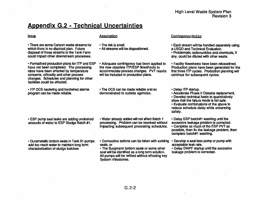
Appendix G.2 - Technical Uncertainties
.I.ssWi
• There are some Canyon waste streams for which there is no disposal plan. Future disposal of these streams to the Tank Farm could impact other downstream processes.
• Formalized production plans for ITP and ESP have not been completed. The processing rates have been effected by temperature concerns, criticality and other process changes. Schedules and planning for other facilities could be effected.
• ITP DCS neutering and hardwired alarms program can be made reliable.
• ESP pump seal leaks are adding undesired amounts of water to ESP Sludge Batch #1.
• Durametallic bottom seals in Tank 51 pumps add too much water to maintain long term characterization of sludge batches
Assumption
• The risk is small. • All streams will be dispositioned.
• Adequate contingency has been applied to the now obsolete ITP/ESP flowsheets to accommodate process changes. PVT results will be included in production plans.
• The DCS can be made reliable and so demonstrated to outside agencies.
• Water already added will not affect Batch 1 processing. Problem can be resolved without impacting subsequent processing schedules.
• Correective actions can be taken with existing seals, or • The Burgmann bottom seals or some other seal will be identified as a long term solution. All pumps will be refitted without effecting key System milestones.
G.2-2
High Level Waste System Plan Revision 3
Contingency/Action
• Each stream will be handled separately using a USQD and Technical Evaluation. • Problematic radionuclides and chemicals, if any, could be diluted with other waste.
• Facility flowsheets have been rebaselined. Production plans have been generated for the first three ITP cycles. Production planning will continue for subsequent cycles.
• Delay ITP startup. • Accelerate Phase II Classics replacement. • Develop technical basis to quantitatively show that the failure mode is fail-safe. • Evaluate combinations of the above to reduce schedule delay while enhancing safety.
• Delay ESP batch#1 washing until the excessive leakage problem is corrected. • Complete as much of the ESP PVT as poSSible, then fix the leakage problem, then complete batch#1 washing.
• Develop a seal-less pump or pump with acceptable leak rate. • Delay DWPF startup until the excessive leakage problem is corrected.

High Level Waste System Plan Revision 3
Appendix G.2 - Technical Uncertainties
~
• The Waste Removal program scope is limited to water washing the tank interior and annulus for each old-style tank to be retired. Additional cleaning, possibly chemical cleaning, may be required prior to turning the tank over to the ERWM Division.
• The precipitate inventory in Tank 49 is limited to 565,000 gallons based on an average precipitate concentration of 39 Ci/gal. HLW System attainment is restricted by this limit.
• Initial salt samples from Tank 41 indicate that chromium levels in the dissolved salt will exceed the DWPF glass limit and insoluble solids will exceed the Tank 48 process requirement.
• "Assured Confinement" modifications to the DWPF Vitrification Building and Late Wash Auxialiary Pump Pit are not clearly defined.
Assumption
• Water washing will be adequate. If further cleaning is required, then an ERWM cost funded project will provide the facilities and operations.
Contingency/Action
• Chemical cleaning has been successfully demonstrated using dilute oxalic acid in Tank 16. This process may be applicable to other sludge tanks.
• Actions will be identified and implemented to • Operate the HLW System at reduced enable the Tank 49 level to return to the attainment during the periods of high original OSA. precipitate generation.
-Insoluble solids and chromium in Tank 41 dissolved salt will be less than expected or will be allowed to settle prior to feed to ITP.
• Modifications can be completed without delaying DWPF or Late Wash startup and within existing project estimates.
G.2-3
•
• Studies to define requirements will be completed in FY94. Scope and schedule of modifications will be developed. There is some project cost and schedule contingency.


High Level Waste System Plan Revision 3
Appendix H - DOE Milestones
ADS
21-AA
22-AA
Title
DWPF Program Management
• Complete response and modification of Waste Form Compliance Plan per DOE-RW comments • Complete implementation, including evaluation of FA-13 melter run, of Waste Qualification activities
DWPF Vitrification
• Start melter simulator training • Transmit Change Control package to support Reprogramming • Complete melter vacuum protection mods • Submit and present responses to DOE comments on General section and Chapters 1,7,13,14, of the SAR • DWPF CCR Issue resolution/path forward including cost & schedule • Transmit SAR Chapters 9 & 11 to DOE • Start construction of APP mods • Issue revised DWPF Startup Plan and criteria to address melter milestones to DOE-SR • Submit responses to DOE comments on chapters 3, 6, 8, and 10 of the SAR • Complete response and modification of Waste Form Compliance plan per DOE-RW comments • Start melter offgas Operations testing • Start melter preparation outage • WSRC ready for melter testing (low power) • Complete DWPF safety class study • Start process and decontamination frit slurry system operation with frit or provide workaround to DOE by 4/30/94 • Evaluate safety classification study and recommend path forward • Complete Phase III RIDS for 90-2 for DWPF
H-l
.Ihm
1/30/94
9/30/94
10/18/93c 11/26/93c 12/15/93c 12/15/93c
1/14/94c 1/15/94c 1/17/94c 1/21/94c 1/30/94c 1/30/94c
2/2/94c 3/1/94c
4/11/94c 5/13/94
5/20/94c
6/1/94 6/1/94

High Level Waste System Plan Revision 3
Appendix H - DOE Milestones
ADS
23-AA
31-AA
32-AA
Ii1Le
• Upgrade existing Phase I Order Compliance Information using 8B requirements • Upgrade existing Phase II Order Compliance Information current knowledge pers for DWPF • Start melter operation • Complete APP Late Wash Bypass Modifications • Start NH/H2 mods outage • Start radioactive operations
Z-Area Saltstone
• Commence Saltstone Demo Run • Complete Title II design for vault#4 permanent roof • Complete revised Title II design for Vault#2
HLW Program Management
• Transmit rev. 2 HLW System Plan to DOE with liquid waste activities as required for continued operation of DWPF • Complete "pipeline" training course and assign operators to the field • Complete Shift Manager and STE training courses • Provide first working HLW System flowsheet model • Complete implementation of Oral Boards for interim qualifications of STE's for H-Tank Farm • Post radiological buffer areas in HLW facilities
H-Tank Farm
• Issue WSRC request for DOE approval for 1 H Evap restart • DOE approval of 1 H Evaporator startup
H-2
Dwl
6/1/94 6/1/94
6/4/94 6/26/94 8/25/94
12129/95
4/1/94c 5/15/94 8/30/94
1/14/94c
5/31/94 5/31/94 6/30/94 9/30/94
9/30/94
12/13/93c 12/20/93c

High Level Waste System Plan Revision 3
Appendix H - DOE Milestones
ADS
33-AA
34-AA
Title
• Issue WSRC request for DOE approval for 2H Evap restart • DOE approval of 2H Evaporator startup • Complete 2H Evaporator outage including feed pump replacement • Recover 600,000 gallons of tank space based on evaporation, CRC operation, generator reduction, etc.
F-Tank Farm
• Issue WSRC request for DOE approval for 2F Evaporator restart • DOE approval of 2F Evaporator startup • Recover 350,000 gallons of tank space based on evaporation, generator reduction, etc.
ITP/ESP
• Start modification outage • Transmit Startup Plan to DOE-SR • Submit rebaselined schedule/cost Change Control proposal • Complete ITP training • Complete modification outage • Start Tank 42 Process Verification Test • Upgrade existing Phase I Order Compliance Packages to meet 88 requirements • Issue WSRC approved OSR's • Issue WSRC approved SAR addendum • Start integrated solids testing • Conduct ITP ORR Emergency Preparedness exercise • Start operator quiet time • Complete benzene/integrated solids testing • Issue WSRC approved geotechnical basis & JCO • Issue seismic evaluation of tanks
H-3
~
4/23/94c 4/30/94c 7/25/94 9/30/94
3/24/94c 3/31/94c 9/30/94
12/14/93c 12/31/93c 12/31/93c
2I28/94c 4/1/94c
4/19/94c 6/1/94
6/30/94 6/30/94 7/21/94 7/21/94 8/14/94 7/29/94 7/31/94 7/31/94

High Level Waste System Plan Revision 3
Appendix H - DOE Milestones
AIm Title
• Upgrade existing Phase II Order Compliance information with RSA packages and complete Phase I & II assessments • Issue Engineering evaluation of ESP Process Verification Test results • Start continual Phase II Order Compliance self-assessments • ITP ready for DOE ORR
38-LI HLW New Facility Planning
• Provide summary report on reduction options for DWPF recycle • Provide summary report on reduction options for the ESP washwater • Complete Tank Farm Services Upgrade CDR and WSRC approved Project Plan
39-LI New Waste Transfer Facility
310-LI
311-LI
• Issue WSRC approved rebaselined schedule for NWTF • Full hot operations
Replacement HLW Evaporator
• Complete evaporator building structural concrete • Convert the RHLWE construction site to a non-RCA • Complete main enclosure building structural steel • Complete Title II Design Activities • Submit a WSRC approved resource loaded schedule that includes detailed construction activities and all known interfaces with other projects • Start radioactive operations
Diversion Box & Pump Pit Containment
H-4
~
8/1/94
8/26/94 9/1/94
9/26/94
12/31/93c 1/31/94c 1/31/94c
5/1/94c 11/29/95
12/31/93c 3/31/94c 3/31/94c 4/30/94c 6/15/94
11/17/97

Appendix H - DOE Milestones
ADS :mIg
• Complete HPP-5&6 restoration • Begin Pre-Operational Testing • Construction Complete • Project Completion
314-LI HLW Removal from Filled Waste Tanks
• Submit waste removal schedule required by the FFA • Transmit to DOE the Tank 29 resource loaded startup schedule • Transmit WSRC recommendation for alternate startup approach • Begin Tank 29 DCP conversion 1 month after approval of BCP-023 • Begin TEC/OPC iteration process • Provide initial cost and schedule rebaseline • Begin S-3025 Title I design within 1 month of KD#1 • Provide a validation package • Provide BCP to support rebaseline • Provide draft ESAAB Package • Complete D&R activities on Tank 29 risers
45-LI Consolidated Incineration Facility
Notes:
• Complete construction • Physical trial burn • Commence operation of the CIF (KD#4)
c = complete n = need date, no current supporting schedule tbd = to be determined
H-S
High Level Waste System Plan Revision 3
.Qyg
2/26/94c 3/1/95
3/30/95 6/30/95
11/12/93c 12/1/93c 1/31/94c 2n/94c
3/25/94c 4/18/94c 4/28/94c
5/2/94c 5/16/94c S/23194c 7/31/94
3/29/95 10/26/95
2/2/96


Appendix I - Summary of Waste Receipts
High Level Waste System Plan Revision 3
[ Year! F-LHWI F-HHWI H-LHWI H-HHWI RBOFI 299-HI Trailersl ErFI
1954 35312 35 710 0 0 * 0 * 0 1955 790 681 984 200 244 918 650,400 * 0 * 0 1956 411 019 487352 430 200 839,610 * 0 * 0 1957 72450 85 730 415 471 497,270 * 0 * 0 1958 0 0 231 900 298 000 * 0 * 0 1959 501,939 485,102 47,238 941 963 * 0 * 0 1960 1,279.014 808.004 2 923 402 173 * 0 * 0 1961 993 765 3,217-,-965 9 947 475 422 * 0 * 0 1962 1,432,980 615,407 6 576 733 456 * 0 * 0 1963 1,227702 688,965 199,462 540 521 * 0 * 0 1964 1.391.284 803.040 199.532 440 734 * 0 * 0 1965 485-,-954 727.401 438.320 942 297 * 0 * 0 1966 776,029 258~063 550-,--880 1 243,328 * 0 * 0 1967 747 113 274 016 551.282 897,197 * 0 * 0 1968 688 240 231 262 727.481 721 376 * 0 * 0 1969 930 389 260 835 752.401 864 951 * 0 * 0 1970 862 795 192 938 769,549 814 794 * 0 * 0 1971 671 327 234343 708,166 994 926 * 0 * 0 1972 929 256 214 344 841 294 813,327 * 0 * 0 1973 1 089.842 322,290 921,378 893.976 * 0 * 0 1974 814 768 182 416 788 090 623.887 * 0 * 0 1975 527 736 72477 350 381 542.966 * 0 * 0 1976 906,700 127,000 549 000 444,000 1,264,000 0 63 000 0 1977 756,500 69,000 455 000 486 000 647,000 0 28500 0 1978 804,000 129,000 496 000 419 000 624,000 0 29 000 0 1979 798.000 187,000 575 000 511 000 716,000 0 41,000 0 1980 1 131 000 216,000 642,000 554 000 644,000 0 8 000 0 1981 1 323 000 271 000 392,000 574 000 442 000 0 5,000 0 1982 1 093 000 279 000 425,000 380 000 45 000 0 7000 0 1983 1 684 000 297 000 508,000 427 000 853 000 0 86.000 0 1984 . _ 2,122,00.0 419 000 532.000 513,000 1,293,000 0 98,000 0
- ----
1- 1

Appendix I - Summary of Waste Receipts
High Level Waste System Plan Revision 3
r -- Yearr:uF=-LHwl F-HHwl- H-LHwl .- H+iHW1 --- RsOFT ·299-HI Trailersl ETFI
1985 2 146 000 580,000 441 000 601 000 991 000 34 000 25,000 0 1986 1 381 000 353,000 397 000 503 000 783 000 79 000 44,000 0 1987 t .. 312.000 380.000 331 000 394 000 1.157.000 157 000 35,000 0 1988 1.345.000 304.000 169 000 174000 847.000 176 000 5,000 0 1989 557 000 128,000 203 000 95 000 1,000-,000 80 000 0 304,000 1990 169,900 39 500 62,000 8 000 131,000 13,000 0 223 000 1991 209,500 18 000 106,000 20,000 391,000 8 000 14 000 190 000 1992 88,000 2,000 58,000 0 282,000 22,000 110 000 128 000 1993 66.000 12 000 72,000 21,000 265,000 3,000 0 149 000 ---_ .... -
Total! 34,552,1951 14,992,3601 15,600,3891 21,296,5741 12,375,006[ 572,OOOC·· 598,500C 994,0001
Notes; • all data obtained from HLW Engineering Monthly Data Records • ETF receipts were ETF evaporator bottoms to Tank 50 * data not available at time of this Plan
1- 2

Appendix J.1 - Salt Removal Schedule High Level Waste System Plan
Revision 3
2
3
4 5
6
7
8
9
10
11
12 13
14 15
38
39
40
START TYPEI&II
TANK TANK TANK TANK TANK 2 3 10 14
8194
1/96
11196
5/97
11/97
4198
9/98
4/99
9/99
3/00
8/00
1101 8/01
2FEVAPSYSTEM II 1 H/RHLW EVAPSYSTEM TANK TANK TANK TANK TANK TANK TANK TANK TANK TANK TANK TANK TANK
2H EVAP SYSTEM
TANK TANK TANK 25 27 28 44 45 46 38 41 43
J-1


Appendix J.2 - Sludge Batches and Sequencing
aamh
1
2
3
IanI1
15 18 21 22
8 11 15
4 7
12 14 47
Volume La.all
126,000 376,000 182,000
30,000
714,000
173,000 164,000 140,000 312,000
789,000
127,000 206,000 215,000
27,000 248,000 823,000
Avail. Volume
91,000 341,000 182,000
30,000 -147,000 497,000
173,000 164,000
70,000 156,000 -88,000 475,000
127,000 206,000
~
AI dissolution (actual)
remaining heels in Tanks 42 & 51
sludge already in Tank 40
AI dissolution 2:1 AI dissolution 2:1 remaining heel in Tank 40
108,000 AI dissolution 2:1 13,000 AI dissolution 2:1
248,000 Sludge remaining after salt removal 702,000
J ,2-1
High Level Waste System Plan Revision 3

High Level Waste System Plan Revision 3
Appendix J.2 - Sludge Batches and Sequencing
B.a1Q.h
4
5
6
~
5 6 9
10 13 26 35
1 2 3
32 33 34 39 43
17 18 19 21 22 23 24
Volume UJ.all
34,000 25,000
4,000 4,000
251,000 298,000
52.000 668,000
7,000 4,000 4,000
157,000 42,000 45,000
101,000 199,000
559,000
2,000 42,000 20,000 14,000 60,000 43,000
4,000
185,000
Avail. Volume
34,000 25,000
4,000 4,000
188,000 298,000
26.000 579,000
7,000 4,000 4,000
79,000 42,000 45,000 50,000
199,000 88.000
518,000
2,000 42,000 20,000 14,000 60,000 43,000
4,000 147.000 332,000
~
Sludge remaining after salt removal Sludge remaining after salt removal AI dissolution 4:3 2F Evap. shut down during sludge removal AI dissolution 2:1
Sludge remaining after salt removal Sludge remaining after salt removal Sludge remaining after salt removal AI diss. 2:1, RHLWE down during sludge rem.
AI dissolution 2:1 2H Evap. shut down during sludge removal Tank 51 heel removed at end of batch feed
residual heel from 1985-6 sludge rem. campaign residual heel from 1985-6 sludge rem. campaign residual heel from 1985-6 salt rem. campaign residual heel from 1985-6 sludge rem. campaign residual heel from 1985-6 sludge rem. campaign
residual heel from 1985-6 salt rem. campaign Tanks 42 & 40 heels removed at end of batch feed
J.2-2

en en I ... a. <:
(1) (.) C'O
ex> en
en I
... a. ~
« C
C'O .... (1)
-.tl "
C'O en I
-...
. -a.
M
C'O <:
I
>
"""")
<t • (W
) • <
0
.., en I
>< ...
.-a.
'tJ <:
C
(1)
<t It)
en I ... a. <:
~
en I ... a.
0 0
0 0
0 0
0 0
0 0
0 <:
0 0
0 0
0 0
0 0
0 0
0 0
0 0
0 0
0 0
0 0
0 0
0 0
0 0
0 0
0 0
0 0
0 0
0 0
0 0
0 0
0 It)
0 It)
0
It)
0 It)
0
It)
It)
~
~
('I) ('I)
C\I
C\I
..... .....

ADDendix J. 4 - Tank Farm Material Balance (Database}
High Level Waste System Plan Revision 3
-. Unfluents J IEffluents IIIITo1a1 I I ~ IF-lHW IF-HHW IH-lHW IH-HHW IRBOF hOO-Al8asloWPF IESP 11H Ewp 12H Evap 12F Evap IRHlWE IITP ~SpaceNo1es ~ 885 113 Actual lank space @ bellinnina of balance ~ 20000 500 15000 0 30000 0 0 0 0 104167 41667 0 0 965,447
Jun-94 20,000 500 15,000 0 30000 0 0 481 748 0 104167 83333 0 0 605699 ~ 20,000 500 15,000 0 30000 0 0 0 010416783333 0 0 481748 1~09,447ESPwasnwalerloTk24 ~ 24000 17940 30000 0 30000 0 0 350000 0 104167 83333 0 0 945,007 ~ 24000 19,200 30 000 0 30,000 0 0 0 0 104 167 83 333 0 0 350 000 1 379,307 ESP washwaler 10 Tk 24 ~ 20000 19,200 30000 0 30,000 0 0 350000 0 104167 83 333 0 0 1117,607 Nov-94 20000 1700 15000 0 30000 0 0 0 0104167 83333 0 0 1,238,407 ~ 20000 1700 15,000 0 30000 35,200 0 225000 0 104167 83333 0 0 1099,007
Jan-95 20000 500 15000 0 30000 0 0 0 0 104167 83333 0 0 1221007 "Fab:95 20 000 500 15 000 0 30 000 0 0 0 0 I 04 I 67 83 333 0 0 1 343 007 ~ 24,000 500 15000 0 30,000 0 0 0 0 104,167 83,333 0 130000 1,591,007 Tank38conesuplolTP ~ 30,500 500 15,000 0 30,000 0 0 0 0 104167 83,333 0 0 1,702,507 ~ 27000 500 15000 0 30,000 0 0 0 0 0 83,333 0 0 1713,340 ~ 24000 1 700 15000 0 30,000 0 0 0 0 0 83333 0 25000 1 750,973 Tank 38 cone sup 10 lIP ~ 24 000 6 500 15000 0 30 000 0 0 0 0 0 83 333 0 0 1 758,806 ~ 30500 1700 15000 0 30000 0 0 0 0 0 83,333 0 0 1,764939 ~ 27000 1 700 15,000 0 30,000 0 0 0 0 0 83333 0 50000 1 824,572 Tank 38 cone SUD 10 ITP
Ocl-95 30,500 1 700 15,000 30,000 30,000 0 0 0 0 0 83,333 0 0 1 800,705 ~ 30500 6500 15000 34000 30000 0 0 0 0 104167 83333 0 250000 2122205 Tank32-200 kgal Tank38-50k!lalloITP ~ 30 500 1 700 15000 20 000 30 000 35--200 0 0 0 104 167 83 333 0 0 1,200 000 3 377 305 Tk 42 as Emerergencv Spare
Jan-96 30 500 6 500 8 500 20 000 30 000 0 185 760 0 0 104 167 83 333 0 0 3,283,545 ~ 30500 6500 8500 20000 30000 0 108000 0 0 104167 83333 0 0 3.267545
Mar-96 30 500 6 500 500 20 000 30 000 0 108 000 0 0 104 167 83 333 0 0 3 259 545 ~ 20000 6500 500 20000 30000 0 108000 0 0 104167 83,333 0 50000 3312,045 ank38conesuplo!lP ~ 20000 6,500 500 20,000 30,000 0174982 0 0104167 83333 0 50000 3297583 Tank 38 conesupl0 ITP
Jun-96 37500 6500 500 20,000 30,000 0 174,982 0 0 104167 83333 0 50,000 3,265,581 Tank 38 cone SUP 10 ITP ~ 37500 500 500 18876 30,000 0174,982 0 010416783,333 0375000 3,565,723 Tank29-75kgal Tank32-300kgal ~ 37500 500 500 21780 30,000 0 174,982 0 0 104167 83333 0 400000 3,887961 Tank29-50kgal Tank32-350kgailoITP ~ 20,000 7500 500 21780 30,000 0 174,982 0 0 104,167 21000 0 0 3,758,366
Oct-96 20,000 7,500 20460 21,780 30,000 0 174,982 0 0 104,167 21000 0 0 3608,811 ~ 20000 7500 21 300 21 780 30,000 0 174,982 0 0 104167 21,000 0 25000 3483,416 Tank 29 cone sup 10 ITP -o;;:gs 20000 500 21 300 19602 30000 35200 174982 0 0 104167 21 000 0 30000 3336999 Tank 29 cone Sup 10 ITP ~ 20000 500 21300 19723 30000 0 174982 0 0 104167 21000 0 225000 3420661 Tank29-175kgal Tank38-50k!lalloITP ~ 20,000 500 21300 21,296 30,000 0 181,894 0 0 104,167 21000 0 0 3,270,838 ~ 20,000 500 20,670 21538 30,000 0 181,894 0 0 104,167 21,000 0 375000 3,496,403 Tks27&28-100 kgal each Tk29-175kgailolTP ~ 20,000 500 20,705 18,634 30,000 0 181894 0 0 104,167 21000 0 0 3,349,837 ~ 20,000 500 21160 19360 30,000 0 181,894 0 0 104167 21000 0 50000 3252,090Tank38conesuploITPTank41empl~
~ 20000 500 21,230 6,413 30,000 0 181,894 0 0 104167 21,000 0 0 3,117,220 JiJID 20,000 500 20390 7139 30,000 0 181894 0 0 104167 21000 0 0 2,982,464 I ~ 20000 500 20600 20207 30,000 0 181894 0 0 104167 21000 0 0 2834,430 ~ 20000 500 16855 20207 30000 0 181894 0 0 104167 21000 0 1300000 3990141 Tk 41 relurn 10 saltserviee
Oct-97 20,000 500 17,065 20086 30,000 0 181,894 0 0 104167 21000 0 0 3,845763 ~ 20000 500 20,845 20,086 30,000 0 181,894 0 0 104167 21000 0 0 3697605 ~ 20000 500 20845 8,954 30,000 35,200 181894 0 0 104167 21,000 62500 0 3587879
Jan-98 20 000 500 20 810 28,556 30 000 0 181 894 0 0 104 167 2 I ,000 62 500 0 3 493,786 ~ 20000 500 20810 26741 30000 0 188,806 0 0 104167 21000 62,500 0 3,394,596 ~ 20000 500 17590 26741 30,000 0 188806 0 0 104167 21000 62,500 0 3298626 ~ 20000 500 23260 26741 30000 0 188806 0 0 104167 21000 62500 0 3196986 ~ 20000 500 22735 20207 30000 0 188806 0 0 104167 21000 62500 0 3102405
Jun-98 20000 500 22,735 20570 30000 0 188,806 0 0 104167 21000 270,000 0 3,214,961 7uWa 20000 500 22,735 20,570 30000 0 188,806 0 0 104167 21000 270,000 0 3,327517 ~ 20000 500 20,845 20570 30,000 0 188,806 0 0 104,167 21,000 270,000 0 3,441,963 ~ 20 000 500 20 950 20 570 30 000 0 188,806 0 0 104, 167 21,000 270 000 0 3 556 304
Oct-98 20000 500 20950 7502 30000 0 188806 0 0 104167 21,000 270,000 0 3683713 ~ 20000 500 20,950 4356 30,000 0188,806 0 0104167 21,000270000 0 3,814,268 ~ 20,000 500 20,950 2,178 30,000 35200 188,806 0 0 104167 21,000 270,000 0 3,911,801 ~ 20,000 500 17170 2,178 30,000 0 188,806 0 0 104,167 21,000 270,000 0 4,048,314 fa6:fg 20000 500 16260 2178 30000 0 195718 0 0 104167 21000 270000 0 4178825 ""'Mar:99 20 000 500 15 630 2 178 30 000 0 195 718 0 0 104 167 21 000 270 000 0 4 309 966 ~ 20,000 500 15,630 0 30,000 0 195,718 0 0 104,167 21000 270,000 0 4,443,285 ~ 20,000 500 15,630 0 30,000 0 195,718 0 0 104,167 21000 270,000 0 4,576,604
Jun-99 20,000 500 15,630 2,800 30,000 0 195,718 0 0 104,167 0 270,000 0 -1,200,000 3,486,123 2F assumed 10 fail, Tk 42 relurned 10 ESP service ~ 20000 500 15,000 0 30000 0 195718 0 0 104167 0 270,000 0 3,599,072 ~

Au!l-99 20000 500 t5000 0 30000 0 t957t8 936000 0 t04 t67 Sep-99 20000 500 25400 0 30000 0 195718 110442 0 104167 Oct-99 20000 500 15000 0 30000 0 195718 0 0 104167 Nov-99 20000 500 15000 0 30000 0 t95718 0 0 104167
_Oe~ ~.Ooo 500 ~ .. 15...Q00 - J) ~0.000 35,200 l!1.S.718 L-._ ~ '----- --.J) 1Q4.16Z
l:Ima: • F-LHW: F-Canyon down 5194 - 7/94. operates 8194 - 9194. down 10194 - 3195. restarts 4195. uptime flows per ASD-NMP-93-OO9 • F-HHW: F-Canyon down 5/94 - 7194, operates 8194 - 9194, down 10194 - 3195, restarts 4195, uptime flows per ASD-NMP-93-009 , H-LHW: H-Canyon down 5194 - 9195, restarts 10/95, uptime flows per ASD-NMP-93-OO9 • H-HHW: H-Canyon down 5194 - 9195, restarts 10195, uptime flows per ASD-NMP-93-OO9
0 270000 0 270000 0 270000 0 270000
21.000 270.000
• RBOF planning basis is 100,000 gaVmo to the Tank Farm of which 70,000 gaVmo is not generated, or is processed by the Tank 32 CRe or the GP Evaporator. • Reactor Basin sludge transported to the Tank Farm assumed to be the historical average of 35,200 gaVyr • DWPF recycle is a function of the planned attalnment and age of DWPF for the 6 batches of sludge • ESP washwater is planned to be about 4,400,000 gaVbatch including water washing the old-style tanks when waste removal is complete. , 1 H Evaporator is assumed to remain down indefinately • 2H Evaporator is assumed to fail or be replaced starting 5/95 and require a 6 month outage. Space gain is a factored historical average. • 2F Evaporator is assumed to fail 6199 and require a 8 month outage. Space gain is a factored historical average. • RHLWE is planned to start up 11197 and operate at ascending capacity. • ITP is planned to start up 12194, operate at low attainment through 3196, and on the normal 157 day cycle thereafter. • The "Other" column shows transfers of dilute waste out of Type III tanks for use as waste removal water and the changing use of Tank 42 as emergency spare.
0 0 0 0 0
SR,776.02t t=I 2.768.128 2.881.0nl 2.994.026 3.092.n5
• The 'Available Space' column shows the useable tank space in Type III tanks, i.e., this does not count the 1,300,000 gallons of emergency spare space required in each Tank Farm nor the ITPIESP tanks.
J-4

0 .., c: CD >
c: -
0'1
CD 0'1
.., '-.-I
ca .., .-.-(,) CD l-
e.. 0
)
~
LO
~
co I
0'1 'J
c: '-.-I
ca l-I
an • .., >< .-
r--.. "'C
0'1
c: '-.-I
CD
«
~
0'1 '-......
0 0
0 0
0 0
0 0
0 0
0 0
0 co
II)
~
C")
C\I
T""


High Level Waste System Plan Revision 3
Appendix K - High Level Waste Management Manpower
ADS # I..i1JJl ~ ~ .EYa6. Em .rnm rna fYQQ
21-AA DWPF Program Management 37 46 44 43 43 43 43 22-AA Vitrification 921 961 948 884 859 835 834 23-AA Saltstone Z-Area 47 59 60 81 81 81 81 24-GP General Plant Projects 0 0 0 0 0 0 0 25- LI New Facility Planning 0 0 0 0 0 0 0 26- LI Defense Waste Processing Facility Q. Q. Q. Q. Q. Q. Q.
Total Defense Waste 1,005 1,066 1,052 1,008 983 959 958
31-AA HLW Program Management 126 172 171 171 169 164 161 32-AA H-Tank Farm 344 338 354 387 413 433 442 33-AA F-Tank Farm 258 241 246 265 270 276 278 34-AA ITP/ESP 312 322 309 298 311 311 307 35-AA Effluent Treatment Facility 122 118 116 115 115 115 118 37-GP HLW General Plant Projects 0 0 0 0 0 0 0 38-LI HLW New Facility Planning 3 1 2 3 7 9 13 39-LI New Waste Transfer Facility 51 48 9 0 0 0 0
310-LI RHLWE 20 62 87 92 35 0 0 311 -LI DB & Pump Pit Containment 1 0 0 0 0 0 0 312-LI Hazardous LLW Processing Tanks 0 0 0 0 0 0 0 313 -LI Inter-Area Line Upgrade 0 0 0 0 0 0 0 314 -LI Waste Removal 73 68 79 79 83 96 87 315 -LI Tank Farm Services Upgrade Q. Q. a 5. a Q. Q.
Total High Level Waste 1..ll.O. 1.310 1.373 j --4 to 1.403 1.404 1.406
Total HLW Management Division 2,315 2,436 2,425 2,418 2,386 2,363 2,364
Subcontractors 2.Q.Q B...O. M !.Q II .0. Q.
Total FTE's 2515 2516 2475 2458 2400 2363 2364
K-1


Appendix L - HLW Priorities
1 . Essential Base Program
1 a. health & safety of workers & public 1 b. stewardship of current waste inventories 1 c. improvement programs critical to 1 a and 1 b 1 d. maintenance of facilities to ensure 1 a and 1 b
2. "In Progress" projects/programs to handle waste safely
2a. Evaporator operations
High Level Waste System Plan Revision 3
2b. In-Tank Precipitation (ITP startup/Tank 41 salt removal) 2c. Saltstone operation and vault capping 2d. L-ETF Operation 2e. M-Area Waste Disposal (Sludge Stabilization)
3. High Level Waste System to support DWPF startup and continued operation at low attainment
3a. DWPF Vitrification and Late Wash startup 3b. ESP batch#1 processing 3c. Waste Removal as required to maintain evaporator operation 3d. New Waste Transfer Facility startup 3e. Replacement High Level Waste Evaporator 3f. Waste Removal as required to feed DWPF
4. Increased System attainment, improvement programs and new projects
L-1


High Level Waste System Plan Revision 3
Aggendix M - Funding (S x 1 :lOOO) AOP a.e FYP
ADS # I.i.11.a ~ EYa5. EYa2 E.Yaz ma ~ .EYQQ
21-AA DWPF Program Management 18,244 31,193 30,508 31,934 32,759 34,676 36,010 22-AA Vitrification 148,987 160,513 158,176 152,306 158,285 158,677 166,652 23-AA Saltstone Z-Area 11,352 13,217 19,307 26,206 22,934 29,600 22,022 24-G P General Plant Projects 0 1,000 1,500 2,356 3,214 3,326 3,443 25- LI DWPF New Facility Planning 0 0 0 43 2,544 2,613 4,364 26-LI DWPF (Line Item) 63,509 45,057 0 0 0 0 0
31-AA HLW Program Management 33,645 54,722 55,141 58,498 59,492 61,688 64,507 32-AA H-Tank Farm 63,708 64,799 66,854 68,495 73,169 78,021 79,956 33-AA F-Tank Farm 39,018 41,639 42,431 44,829 46,273 48,840 49,630 34-AA ITP/ESP 82,512 64,155 61,363 64,508 63,717 65,761 65,762 35-AA Effluent Treatment Facility 18,107 24,221 22,984 23,039 22,630 23,041 23,245 37-GP HLW General Plant Projects 0 1,000 3,000 3,130 3,279 3,480 2,080 38-LI HLW New Facility Planning 2,623 1,258 1,643 3,179 7,180 11,406 11,558 39-LI New Waste Transfer Facility 3,388 5,877 932 0 0 0 0
310-LI RHLWE 14,302 25,860 21,392 17,656 4,010 0 0 311 -LI DB & Pump Pit Containment 2,159 136 0 0 0 0 0 31 4 -L I Waste Removal 30,904 36,122 43,191 47,072 63,356 62,239 66,069 315 -LI Tank Farm Services Upgrade 0 57 4,565 10,200 7,805 473 0
14-AA Defense Programs (Rx Materials) 1,354 3,497 11,508 1,936 121 0 0 36-AA L-Effluent Treatment Facility 8,793 7,105 7,194 6,988 2,581 z..a..a B.2.2
Total High Level Waste 542,605 581,428 551,689 562,375 573~349 584,637 596,120
12-AA DOE Program Support 14,225 9,500 13,899 14,400 14,800 15,100 15,550 3030-1 DOE Program Direction 6,633 7,117 7,455 7,775 8,124 8,475 8,729 3510-2 Performance Assessment 88 1,256 1,192 641 660 680 700 3210-2 FFCAct 538 0 0 0 0 0 0
Other Solid Waste, EIS, Hard $ 63,013 78,957' 74,914 76,291 77,779 79,314 80,871
Total EM-31 627,102 678,258 649,149 661,482 674,712 688,206 701,970
M-1

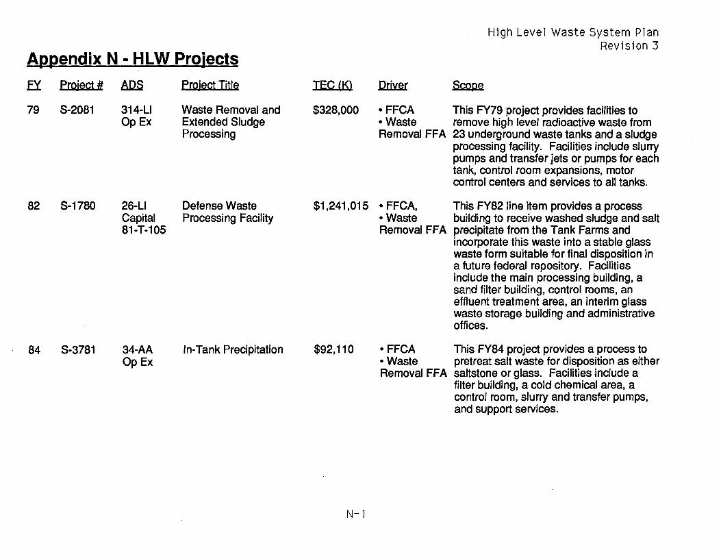
High Level Waste System Plan Revision 3
Appendix N • HLW Projects
EY Project # AIlS EmiectTitle TEC lKl Driver ScoDe
79 S-2081 314-LJ Waste Removal and $328,000 • FFCA This FY79 project provides facilities to Op Ex Extended Sludge • Waste remove high level radioactive waste from
Processing Removal FFA 23 underground waste tanks and a sludge processing facility. Facilities include slurry pumps and transfer jets or pumps for each tank, control room expansions, motor control centers and services to all tanks.
82 S-1780 26-LJ Defense Waste $1,241,015 • FFCA, This FY82 line item provides a process Capital Processing Facility • Waste building to receive washed sludge and salt 81-T-105 Removal FFA precipitate from the Tank Farms and
incorporate this waste into a stable glass waste form suitable for final disposition in a future federal repository. Facilities include the main processing building, a sand filter building, control rooms, an effluent treatment area, an interim glass waste storage building and administrative offices.
84 S-3781 34-AA In-Tank Precipitation $92,110 • FFCA This FY84 project provides a process to OpEx • Waste pretreat salt waste for disposition as either
Removal FFA saltstone or glass. Facilities include a filter building, a cold chemical area, a control room, slurry and transfer pumps, and support services.
N-l

High Level Waste System Plan Revision 3
Appendix N - HLW Projects
.EY Project # AQS Proiect Title IECJKl Driver Scooe
85 S-3122 39-U New Waste Transfer $46,946 • FFCA This FY85 project replaces an existing Capital Facility • Waste obsolete diversion box/pump pit waste 85-D-159 Removal FFA transfer facility with one of current design.
The facility consists of four pump pits with tanks and pumps, one large diversion box, and an enclosure building with remotely operated bridge crane and control room.
87 S-2821 311-U Diversion Box and Pump $24,100 • FFCA This FY87 project provides an enclosure Capital Pit Containment • Rad buildi ng over H-Area Diversion Box no. 7 87-D-181 exposure (HDB-7). Facilities include a remotely
reduction operated bridge crane, a ventilation system, and a mobile control room.
87 S-2787 45-U Consolidated Incineration $87,295 • FFCA This FY87 project provides a facility to Capital Facility • Waste incinerate hazardous, low-level 83-D-148 Removal FFA radioactive, and mixed waste and
particularly the DWPF benzene. Facilities include a large rotary kiln incinerator, offgas treatment, feed storage and ash handling systems and a control room.
87 S-3291 314-U Type III Tanks Salt $31,006 • FFCA This FY87 project provides facilities to OpEx Removal, Phase I • Waste remove waste from three tanks (25, 28,
Removal FFA and 29), support services and process control equipment, and an expansion to control room building 241-18F to support the waste removal operation.
N-2

High Level Waste System Plan Revision 3
Appendix N - HLW Projects
.EY Project # AD.S Ploject Iitle TEC (Kl DIDLer ScoDe
88 5-1588 34-AA ITP Safety and $36,830 - FFCA This FY88 project provides a fire water OpEx Envi ronmental - Waste suppression system, a liquid nitrogen
Enhancements Removal FFA storage and unloading system, two benzene strippers, a laboratory, and other miscellaneous equipment in support of the ITP project.
89 5-2860 314-LI Type III Tanks Salt $121,000 - FFCA This FY89 project provides facilities to OpEx Removal, Phase II - Waste remove waste from two tanks (31 & 47)
Removal FFA and a new control room (241-2H) that will support waste removal from 17 other waste tanks as well as the RHLWE.
89 5-4062 310-LI Replacement High Level $118,200 -Improve This FY89 project provides a cost-Capital Waste Evaporator HLW System effective waste evaporator to replace the 89-0-174 attainment aging 1 H Evaporator and to support the
increased waste load from the DWPF. Facilities include a process cell, a large evaporator with all supporting tanks, pumps and piping, and an enclosure building with remotely controlled crane.
90 5-3066 32-AA Alternate Evaporator $1,000 -FFCA This FY90 projects provides an - Waste uninstalled spare evaporator vessel that Removal FFA can be used in the 1 H, 2H or 2F cell.
93 5-4391 22-AA Late Wash Filter $1,730 -FFCA This FY93 project provides a temporary Op Ex Demonstration Unit - Waste facility to demonstrate and optimize the
Removal FFA Late Wash filtration process.
93 5-5575 38-LI Ion Exchange Skid $865 -Improve This FY93 project provides a facility to Op Ex HLW System demonstrate the IX process using SRS,
attainment Hanford and Oak Ridge simulated waste.
N-3

High Level Waste System Plan Revision 3
Appendix N - HLW Projects
EY Project # AIlS Project Title IEC1Kl Dri'ler ScoDe
93 S-3025 314-U Waste Removal $72,100 - FFCA This FY93 project provides facilities to Capital Facilities, Phase III - Waste remove waste from six tanks (26, 30, 35-(part of 93- Removal FFA 38). Facilities include slurry pumps, 0-187) transfer jets/pumps, support services and
process control equipment.
94 S-5556 22-AA 10MS Ammonia Scrubber $500 -FFCA This FY94 project provides modifications OpEx - Waste to the 10MS demonstration facility to make
Removal FFA it compatible with recent OWPF equipment modifications.
96 S-3898 23-AA Saltstone Vault#2 $17,525 - FFCA This project will provide a reinforced OpEx - Waste concrete 12 cell storage vault for saltstone
Removal FFA grout in support of the ongoing ITP operation. Vault#2 need date 2/98.
96 S-4558 315-U Tank Farm Services $21,070 -Improve This project provides services to replace Capital Upgrade HLW System aging facilities including a) F-Area 96-SR-161 attainment electrical, b) F and H-Area Tank Farm 25,
- Maintain 150 and 325 psi steam, domestic and Tank Farm cooling water, and breathing and infrastructure instrument air lines, c) steam and waste
transfer equipment for Tanks 35-37, and d) increased cooling to support ITP/ESP.
97 W-3014 38-U Sampling/Monitoring $10,000 - Correct This project provides air sampling Capital System Upgrade EPA equipment for waste tanks and process
identified cells as needed in the Tank Farm. deficiencies
N-4

High Level Waste System Plan Revision 3
Appendix N - HLW Projects
EY Project # ADS Project Title ~(K) Driver Scooe
98 tbd 23-AA Saltstone Vault#3 $20,800 • FFCA This project will provide a reinforced OpEx • Waste concrete 12 cell storage vault for saltstone
Removal FFA grout in support of the ongoing ITP operation. Vault#3 need date 12/99.
98 S-4878 38-U ITP Benzene Abatement $14,000 • Clean Air The CAA of 1990 mandated that states Capital Act of 1990 promulgate laws within 10 years to reduce
benzene emissions by 95%. This law, when passed, will apply to ITP which must then comply within 3 years. This proposed project provides a catalytic incinerator at 3 point sources within ITP. Not funded in FY96 FYP Target Case.
98 S-2093 25-U DWPF Salt Cell Benzene $15,000 • Clean Air The CAA of 1990 mandated that states Capital Abatement Act of 1990 promulgate laws within 10 years to reduce
benzene emissions by 95%. This law, when passed, will apply to DWPF which must then comply within 3 years. This proposed project provides a catalytic incinerator at 1 point source within DWPF. Not funded in FY96 FYP Target Case.
98 tbd 2S-U Recycle Stream Volume tbd • Improve This proposed project will provide facilities Capital Reduction HLW System and equipment to reduce the volume of
attainment the DWPF recycle stream. Not funded in FY96 FYP Target Case.
98 S-4881 38-U Tank Farm Storm Water $12,000 • Maintain This proposed project will relieve potential Capital System Upgrade Tank Farm flooding in the Tanks 9-12 area of the H-
safety Area Tank Farm. envelope
N-5

High Level Waste System Plan Revision 3
Appendix N - HLW Projects
EY Project # AIlS Project Title IE~(I{} Driver Scooe
98 S-2048 25-LJ Failed Equipment $4,700 • FFCA This proposed project provides four 98-WM-1 Storage Vaults#3-6 • Waste additional storage vaults to store failed
Removal FFA melters or other equipment that contains high level contamination.
00 W-3008 38-LJ Support Services for $30,000 • improve This proposed project replaces aging Capital Tank Farms HLW System service piping in the F and H-Area Tank 98-SR-387 attainment Farms not covered by project S-4558
including, 25, 150 and 325 psi steam, domestic and cooling water, and breathing and instrument air lines.
00 tbd 25-LJ 703-S Administration $7,000 ·QA This proposed project provides an office Capital Building requirements building to replace numerous temporary 99-SR-184 facilities for 300 people and will enable
DWPF Records Management to meet QA requirements.
00 tbd 23-AA Saltstone Vault#5 $20,800 • FFCA This proposed project will provide a OpEx • Waste reinforced concrete 12 cell storage vault
Removal FFA for saltstone grout in support of the ongoing ITP operation. Vault#5 need date 12101.
N-6

High Level Waste System Plan Revision 3
Appendix 0 - Acronyms
ABC Activity Based Cost FOB F-Area Diversion Box ADS Activity Data Sheet FDC Functional Design Criteria AOP Annual Operating Plan FEIS Final Environmental Impact Statement APP Auxiliary Pump Pit FESV Failed Equipment Storage Vault CAA Clean Ai r Act FFA Federal Facility Agreement CAB Citizen's Advisory Board FFCA Federal Facility Compliance CCR Cold Chemical Runs Agreement CDR Conceptual Design Report FPR Functional Performance Requirements CIF Consolidated Incinerator Facility FAR Foreign Research Reactors Ci/gal Curies per gallon FTE Full Time Equivalent ConOps Conduct of Operations FY Fiscal Year CRC Cesium Removal Column FYP Five Year Plan CTS Concentrate Transfer System ITP In-Tank Precipitation DB&PP Diversion Box & Pump Pit GP General Purpose 0&0 Decontaminate & Decommission GPM Gallons per minute DCS Distributed Control System GWSB Glass Waste Storage Building DOE Department of Energy H&V Heating & Ventilation DP Defense Programs HDA Hydrogen Deflagration Analysis OW Defense Waste HOB H-Area Diversion Box DWPF Defense Waste Processing Facility HHW High Heat Waste EA Environmental Assessment HLW High Level Waste EIS Environmental Impact Statement HLWM High Level Waste Management EM Environmental Management HQ Headquarters - usually as a suffix to EPA Environmental Protection Agency DOE ERDA Energy Research and Development IAL Inter-Area Line
Administration IFM Integrated Flowsheet Model EFWlM Environmental Restoration/Waste IG Inspector General
Management INMDP Integrated Nuclear Material Disposition ESAAB Energy Systems Advisory Acquisition Plan
Board INPO Institute of Nuclear Power Operations ESP Extended Sludge Processing ITP In-Tank Precipitation ETF Effluent Treatment Facility IX Ion Exchange
0-1

High Level Waste System Plan Revision 3
Appendix 0 - Acronyms
JCO Justification for Continued Operation RoN Radioactive Waste, as in DOE Office of LCO Limiting Condition of Operation FW-J LOR Land Disposal Restriction RWPC ROiling Weather Protection Cover LHW Low Heat Waste SAD Safety Assessment Document LI Line Item SAR Safety Analysis Report LPPP Low Point Pump Pit SCDHEC South Carolina Department of Health LW Late Wash and Environmental Control N/A Not Applicable SEIS Supplemental Environmental Impact NEPA National Environmental Policy Act Statement NESHAP National Emissions Standards for SR Savannah River - usually as a suffix to
Hazardous Air Pollutants DOE NFP New Facility Planning S/RID Standards/Requirements Identification NPDES National Pollution Discharge Document
Elimination System SRS Savannah River Site NWTF New Waste Transfer Facility SRTC Savannah River Technology Center OMB Office of Management and Budget ST Sodium Titanate OPC Other Project Costs STP Site Treatment Plan ORR Operational Readiness Review STPB Sodium Tetraphenylborate OSR Operational Safety Requirement SW Solid Waste OTD Office of Technology Development TBD To Be Determined PID Process Interface Document TEC Total Estimated Cost PMP Project Management Plan TOST Technical Oversite Steering Team PRA Probabilistic Risk Assessment TPC Total Project Cost PVT Process verification Test TSD Treatment, Storage and Disposal QA Quality Assurance USQD Unresolved Safety Question RBOF Receiving Basin for Offsite Fuels Determination RCRA Resource Conservation and Recovery WM Waste Management
Act WRP Waste Removal Program RHLWE Replacement High Level Waste WSRC Westinghouse Savannah River
Evaporator Company ROD Record of Decision \N\N Wastewater RSA Readiness Self-Assessment
0-2

High Level Waste System Plan Revision 3
Appendix P - Research and Development Plan
This is a new section in this Plan at the request of DOE-SA. The following outlines a conceptual approach for characterizing and quantifying the HLW System R&D activities provided by the Savannah River Technology Center (SRTC). This Research and Development (R&D) Plan will continue to be developed to eventually become an integral part of the HLW System planning process as well as the supporting budget and manpower planning process.
The HLW System can be functionally described as shown in Figure P.i. At the highest level (level 1), the function is to "Manage High Level Waste". level 2 consists of five sub-functions based on the process used to manage HLW. Level 3 further SUb-divides the Level 2 functions. SRTe support activities will be sorted, defined and managed as further described below.
SRTe supports each HLW System process. Activities range from routine support to long term R&D programs. SRTe provides routine support for only those functions that cannot be performed by the line organizations such as corrosion analysis, nonroutine waste analysis, complex chemistry troubleshooting, etc.
SRTe support can be defined as fitting into one of three categories:
P-1
1) Reference - technology development or technical support required to ensure success of the reference, or baseline, approach,
2) Enhancement - technology that fits within the reference approach that could substantially improve the reference approach or change some feature of the reference approach, and
3) Alternative - technologies that support significantly different approaches that would replace the reference system or significant portions of the reference system
All SRTe support can therefore be shown in a matrix format as shown in Figure P.2. This figure is by no means complete. A sufficient number of cells have entries in them to illustrate the concept. Note that not all cells in the matrix will be filled. Some processes do not have an active enhancement or alternative R&D program while others may have several. Again, the R&D Plan as presented herein is highly conceptual and therefore subject to significant change as it becomes more fully developed.

Hlgh Level Waste System Plan Revlslon 3
Appendix P - Research and Development Plan - Figure P.1
<1> > <1>
....J
<'J
<1> > <1>
....J
I""> -<1> > <1>
....J
store & Evaporate
Waste
• Store • Evaporate • Remove • D&D Tanks
Process Salt
• Decontam 1 n-ate
• Concentrate
• Wash • Remove
benzene
Manage Hlgh Level Waste
Process Sludge
• Dlssolve alumlnum
• Wash
P-2
Vitrify Waste
• Late Wash Preclpltate
• Hydrollze TPB • Prepare mel ter
feed • Vltrlfy Feed • Seal & decon
canlsters
Produce Saltstone
• Feed preparat lon
• Grout product lon
• Grout pumplng • Vaul t capplng

High Level Waste System Plan Revision 3
Appendix P - Research and Development Plan - Figure P.2
llie.l Function
1 Manage High Level Waste
2 Store & Evaporate waste
3 3 3 3
3
• Store • Evaporate • Remove • D&D Tanks
2 Process salt
3 • Decontaminate
3 • Concentrate
3 • Remove Benzene (aqueous)
3 • Remove Benzene (gaseous)
2 Process Sludge
3 3
• Dissolve Aluminum • Wash
- ---
Reference Enhancement Alternative
• Carbon steel tanks • steam evaporators ·IX CRC • Slurry pump agitation • reduce seal leakaae • seal-less oumos • Water wash • chemical decon • section and remove
• fill with grout • entombment • enhanc~d_cl1Etmjcald~con
• ST/STPB adsorption/pre • reverse strike • RF Ion Exchange cipitation with filtration • high NaOH flowsheet • Cobalt di-Carbo/lide • Mott cross-flow • ceramic filtration fi Itratio n • backpulse mods • nitrogen stripping • delete 16" stripper
• antifoam addition • CIF incineration • vendor treatment • vent to atmosphere • reduce discharge • catalytic incineration --- - - -_.- -- -- - -- - -----
• NaOH • batch water wash • washwater reduction
P-3
I
I

High Level Waste System Plan Revision 3
Appendix P - Research and Development Plan - Figure P.2
~
2
3 3 3 3
2
3 3 3 3
Function
Vitrify Waste
• Reduce Nitrite in ppt • Hydrolize TPB • Vitrify feed • Seal & decon canisters
Produce Saltstone
• Feed preparation • Grout production • Grout pumping • Performance Assessmen
Reference Enhancement Alternatiye
• HAN* • Late Wash* • formic acid* • nitric acid* • joule heated melter • stirred melter • weld & frit blast
• cement flvash. slaa i
• mixing I
• diaphragm pumo ,
• isolation cap • oermanent roof • RWPC • oermanent roof • permanent cap • permanent roof • earth overburden
* these examples are used to show how the enhancement or alternative can readily become the reference process as well as how important it is to keep ongoing R&D programs
P-4


HLW-OVP-94-0077, HLW System Plan, Revision 3 (U), May 31, 1994
Distribution:
DOE-HQ R. Erickson, DOE-HO, EM-343 (15) E. Koch, DOE-HO, FM
DOE-SR S. D. Richardson, AMHLW, 704-S A. L Watkins, AMHLW, 704-S C. W. Terrell, HLWPD, 704-S R. J. Schepens, HLWOD, 703-H C. E. Anderson, HLWED, 703-H H. B. Gnann, HLWPD, 704-S R. R. Viviano, WMPD, 703-46A (10) J. C. Truelove, HLWPD, 704-S (75) M. G. Schwenker, HLWED, 703-H
SRTC L. M. Papouchado, 773-A E. W. Holtzscheiter, 773-A W. L. Tamosaitis, 773-A S. D. Fink, 773-A C. T. Randall, 704-T
HLWM Staff A. B. Scott, Jr., 719-4A H. D. H~umon, 719-4A C. L. Peckinpaugh, 719-4A
HLWMPM S. S. Cathey, 719-4A N. R. Davis, 719-4A M. W. Wells, 719-4A R. M. Kanas, 719-4A
DWPF D. B. Amerine, 704-S W. H. Pettigrew, 704-S D. G. Thompson, 704-Z
HLWM Engg T. J. Lex, 719-4A B. G. Croley, 241-120H W. D. Kimball, 704-S J. F. Ortaldo, 704-S (3) J. T. Carter, 704-S (5) J. P. Morin, 719-4A R. M. Satterfield, 719-4A D. T. Bignell, 719-4A W. T. Goldston, 704-S M. J. Montini, 704-S M. Miller, 704-S
N. F. Chapman, 704-24S T. M. Monahon, 703-H V. G. Dickert, 703-H R.A.Scaggs,703-H D. C. Wood, 706-21 C J. N. Brooke, 241-119H R. Salizzoni, 707-H (5) W. C. Clark, 241- (5) M. S. Peters, 241-1 OOF J. E. Marra, 703-H (5) B. L. Lewis, 703-BC (3) R. Brandon, 719-4A
SWER Staff N. C. Boyter, 730-B C. B. Jones, 730-B
HLWM Controller G. Kizer, 719-4A P. M. Kennedy, 704-S M. T. Ligon, 742-9G D. P. Chew, 719-11A L. W. Wiker, 719-11A
HLWM E&PD G. L. Hohmann, 704-71 S R. T. Emerson, 704-24S R. A. Stokes, 5002-H G. M. Johnson, 5002-H
HLWM G. T. Wright, 703-H J. W. French, 703-H E. R. Losure, 707-H (5) G. Davis, 703-F (5) H. M. Handfinger, 5002-H C. J. Baker, 5002-H E. R. Ennis, 241-120H R. W. Wilson, 707-H D. T. O'Rear, 742-2G A. S. Greer, 241-1 02H W. B. Boore, 703-BC M. J. Green, 703-BC M. J. Mahoney, 703-BC J. E. Herbert, 703-H
HLWMCM L. G. Frelin, 742-9G M. T. Keefer, 241-153H K. Rashidi, 742-13G T. E. Pate, 742-13G G. L. Archer, 742-13G
EPD/AP J. R. Roberts, 742-A

![Pfarrbrief April 2018 - pfarreiengemeinschaft-mendig.de€¦ · 3dvvlrqv]hlw kdehq zlu xqv vfkolh olfk ghp 'xqnho lp /hehq -hvx jhvwhoow ... 'dkp -xoldq 7k u +huphv 1lov 7k u 0rqvfkdxhu](https://img.dokumen.tips/doc/110x75/5b550ac97f8b9a27658d9f0e/pfarrbrief-april-2018-pfarreiengemeinschaft-3dvvlrqvhlw-kdehq-zlu-xqv-vfkolh.jpg)


![Mailand - CD / DVD Presswerk | Blu-ray | CD drucken DVD ....dsd]lw¥w.dsd]lw¥w *% *% *% *% *% )duehq)duehq 0dwhuldo0dwhuldo .xqvwvwrii /lhihu]hlw/lhihu]hlw $uehlwvwdjh](https://img.dokumen.tips/doc/110x75/60a721cdccd7a970ef391102/mailand-cd-dvd-presswerk-blu-ray-cd-drucken-dvd-dsdlwwdsdlww.jpg)