Embed Size (px)
Citation preview

MK-96RD626-07
Hitachi Universal Storage Platform V Hitachi Universal Storage Platform VM
Hitachi Universal Volume Manager User’s Guide
FASTFIND LINKS
Document Organization
Product Version
Getting Help
Contents

ii
Hitachi Universal Storage Platform V/VM Universal Volume Manager User’s Guide
Copyright © 2008 Hitachi Data Systems Corporation, ALL RIGHTS RESERVED
Notice: No part of this publication may be reproduced or transmitted in any form or by any means, electronic or mechanical, including photocopying and recording, or stored in a database or retrieval system for any purpose without the express written permission of Hitachi Data Systems Corporation (hereinafter referred to as “Hitachi Data Systems”).
Hitachi Data Systems reserves the right to make changes to this document at any time without notice and assumes no responsibility for its use. Hitachi Data Systems products and services can only be ordered under the terms and conditions of Hitachi Data Systems’ applicable agreements. All of the features described in this document may not be currently available. Refer to the most recent product announcement or contact your local Hitachi Data Systems sales office for information on feature and product availability.
This document contains the most current information available at the time of publication. When new and/or revised information becomes available, this entire document will be updated and distributed to all registered users.
Hitachi, Hitachi logo, and Hitachi Data Systems are registered trademarks and service marks of Hitachi, Ltd. The Hitachi Data Systems logo is a trademark of Hitachi, Ltd.
Dynamic Provisioning, Hi-Track, TrueCopy, ShadowImage, and Universal Star Network are registered trademarks or trademarks of Hitachi Data Systems.
All other brand or product names are or may be trademarks or service marks of and are used to identify products or services of their respective owners.

Contents iii
Hitachi Universal Storage Platform V/VM Universal Volume Manager User’s Guide
Contents
Preface...................................................................................................ix Intended Audience ...............................................................................................x Product Version....................................................................................................x Document Revision Level ......................................................................................x Source Documents for this Revision ......................................................................xi Changes in this Revision ......................................................................................xi Document Organization .......................................................................................xi Referenced Documents....................................................................................... xii Document Conventions...................................................................................... xiii Convention for Storage Capacity Values .............................................................. xiv Getting Help ...................................................................................................... xv Comments ......................................................................................................... xv
Overview of Universal Volume Manager.................................................. 1-1 Hitachi Universal Volume Manager......................................................................1-2 Unifying Copy Operations between Different Storage Systems ..............................1-3 Unifying Connections from a Host to Different Storage Systems ............................1-4
About Universal Volume Operations Manager.......................................... 2-1 Connecting External Storage System...................................................................2-2 Universal Volume Manager Components..............................................................2-4 Storage Systems and Cross-subsystem Paths.......................................................2-5 Volumes and Mapping Paths ..............................................................................2-5 Universal Volume Manager Operations ................................................................2-7 Configuring Universal Volume Manager ...............................................................2-8 Choosing External Port ......................................................................................2-8 Choosing and Mapping External Volumes ............................................................2-8 Registering a Volume to an External Volume Group (ExG) ....................................2-9 Configuring External Volume Attributes ...............................................................2-9 Cross-subsystem Paths ....................................................................................2-11

iv Contents
Hitachi Universal Storage Platform V/VM Universal Volume Manager User’s Guide
Connecting Mainframe Volumes....................................................................... 2-19 Connecting Open Systems Volumes ................................................................. 2-19 Choosing Mapping Policy................................................................................. 2-20 Difference between Automatic Mapping and Manual Mapping............................. 2-20 Port Discovery and Volume Discovery............................................................... 2-20 Using a Mapped External Volume from a Connected Host .................................. 2-22 Storing New Data in the Mapped External Volume............................................. 2-22 Using Existing Data in the Mapped External Volume .......................................... 2-23 Interoperability with other Products and Functions ............................................ 2-25 LUN Manager and Configuration File Loader ..................................................... 2-25 LUN Expansion ............................................................................................... 2-25 Virtual LVI/LUN .............................................................................................. 2-25 Cache Residency Manager............................................................................... 2-26 Performance Manager..................................................................................... 2-26 TrueCopy and TrueCopy for z/OS..................................................................... 2-26 Universal Replicator and Universal Replicator for z/OS ....................................... 2-26 ShadowImage and ShadowImage for z/OS ....................................................... 2-26 Copy-on-Write Snapshot ................................................................................. 2-26 Dynamic Provisioning...................................................................................... 2-27 SNMP Agent................................................................................................... 2-27 Examples of Using External Volumes with Other Products .................................. 2-28 Volume Migration Operations........................................................................... 2-28 TrueCopy Operations ...................................................................................... 2-30 Universal Replicator Operations ....................................................................... 2-32 ShadowImage Operations ............................................................................... 2-34 Copy-on-Write Snapshot Operations................................................................. 2-36
Preparing for Universal Volume Manager Operations ............................... 3-1 System Requirements ....................................................................................... 3-2 Storage Systems Supported as External Storage Systems .................................... 3-2 Universal Volume Manager Requirements ........................................................... 3-5 Guidelines for Universal Volume Manager Operations .......................................... 3-6 Mapping Guidelines .......................................................................................... 3-6 Recommended Applications according to the HDD Type....................................... 3-7 Capacity Guidelines........................................................................................... 3-8 Guidelines for Mainframe Volumes ..................................................................... 3-9 Volume Attribute Guidelines ............................................................................ 3-10 Creating LUSE Volume Guidelines .................................................................... 3-10 Maintenance Guidelines for an External Storage System .................................... 3-11 Performance and Status Guidelines .................................................................. 3-11 RAID Level Considerations .............................................................................. 3-12 Thunder 9500V Series Guidelines..................................................................... 3-12 Installing and Uninstalling Universal Volume Manager........................................ 3-13

Contents v
Hitachi Universal Storage Platform V/VM Universal Volume Manager User’s Guide
Installing Universal Volume Manager ................................................................3-13 Uninstalling Universal Volume Manager .............................................................3-13 Starting Universal Volume Manager ..................................................................3-14
Using the Universal Volume Manager GUI............................................... 4-1 Volume Operation Window.................................................................................4-2 Volume Operation Tree......................................................................................4-4 Volume Operation List (When Subsystem or Product Name is Clicked) ...................4-5 Volume Operation List (When Path Group is Clicked)............................................4-6 Preview Dialog Box..........................................................................................4-10 Path Operation Window ...................................................................................4-12 Path Operation Tree ........................................................................................4-14 Path Operation List (When Subsystem is Clicked)...............................................4-15 Path Operation List (When Product Name is Clicked)..........................................4-17 Path Operation List (When Port or WWN is Clicked) ...........................................4-18 Port Operation Window....................................................................................4-19 Port Operation Tree.........................................................................................4-20 Port Operation List ..........................................................................................4-21
Performing Universal Volume Manager Operations .................................. 5-1 Overview of Setting Operations ..........................................................................5-2 Setting Port of External Storage System..............................................................5-3 Setting Port Attribute for Local Storage System....................................................5-3 Mapping an External Volume Automatically .........................................................5-4 Mapping an External Volume Manually ................................................................5-6 Add Volume Dialog Box .....................................................................................5-8 Set External Volume Parameter Dialog Box........................................................5-10 LDEV Mapping (Auto) Dialog Box......................................................................5-11 LDEV Mapping (Manual) Dialog Box ..................................................................5-13 SSID Dialog Box..............................................................................................5-14 Example: How to Map LDEVs Automatically .......................................................5-16 Example: How to Map LDEVs Manually..............................................................5-17 Setting the Cross-subsystem Paths ...................................................................5-18 Configure Cross-subsystem Paths Dialog Box.....................................................5-19 Configuring Cross-subsystem Path ....................................................................5-21 Changing the Configured Cross-subsystem Path Priority .....................................5-23 Canceling the Cross-subsystem Path Configuration.............................................5-24 Changing the Cross-subsystem Path .................................................................5-25 Replacing All the Cross-subsystem Paths with Newly-added Cross-subsystem
Paths.......................................................................................................5-25 Checking the External Volume Details ...............................................................5-26 LDEV Information Dialog Box ...........................................................................5-27 Mapping Path Information Dialog Box ...............................................................5-28

vi Contents
Hitachi Universal Storage Platform V/VM Universal Volume Manager User’s Guide
Turning On or Off the Storage System ............................................................. 5-30 Commands for Turning On or Off Only the External Storage System................... 5-30 Turning On or Off Only the External Storage System ......................................... 5-31 Turning On or Off Only the Local Storage System ............................................. 5-32 Turning On or Off Both Storage Systems .......................................................... 5-33 Disconnecting External Storage System or Disconnecting External Volume .......... 5-34 Disconnecting All External Volumes (Disconnect Subsystem) .............................. 5-36 Disconnecting an Individual External Volume (Disconnect Volume) ..................... 5-36 Checking Connection Status and Resuming External Volume Operation............... 5-37 Resuming All External Volumes (Check Paths & Restore Volume)........................ 5-38 Resuming an Individual External Volume (Check Paths & Restore Volume).......... 5-38 Stopping the Use of Paths to the External Volume (Disconnect Paths)................. 5-39 Restoring the Paths to the External Volume (Check Paths) ................................. 5-40 Changing the Cache Mode Setting of the External Volume ................................. 5-41 Changing the Inflow Control Setting of the External Volume............................... 5-42 Changing the Port Setting of the External Storage System ................................. 5-42 Change WWN Parameter Dialog Box ................................................................ 5-43 Editing Mapping Policy .................................................................................... 5-44 Edit Policy Dialog Box ..................................................................................... 5-44 Deleting the External Volume Mapping ............................................................. 5-45
Remote Command Devices.................................................................... 7-1 Overview of Remote Command Devices ............................................................. 7-2 Guidelines for Remote Command Devices........................................................... 7-3 Mapping a Command Device as a Remote Command Device ................................ 7-6 Using TrueCopy or Universal Replicator with Remote Command Device................. 7-6 Procedure to Use Initiator/External MIX Mode..................................................... 7-8 Restrictions on Initiator/External MIX Mode ........................................................ 7-9
Troubleshooting ................................................................................... 8-1 Troubleshooting ............................................................................................... 8-2 Calling the Hitachi Data Systems Support Center................................................. 8-6
Connecting External Storage Systems .................................................... A-1 TagmaStore AMS/WMS Storage System ............................................................. A-1
System Parameters for Connecting TagmaStore AMS/WMS Storage System............................................................................................... A-1
Relationship between Serial Number and AMS/WMS Model............................ A-2 Relationship between WWN of Port and Controller (AMS/WMS) ..................... A-3 Path Status and Examples of Recovery Procedure (AMS/WMS) ..................... A-4
Thunder 9500V Storage System......................................................................... A-5 System Parameters for Connecting Thunder 9500V....................................... A-5

Contents vii
Hitachi Universal Storage Platform V/VM Universal Volume Manager User’s Guide
Relationship between Serial Number and 9500V Model ................................. A-6 Relationship between WWN of Port and Controller(9500V)............................ A-6 Path Status and Examples of Recovery Procedure(9500V)............................. A-8
USP V/VM Storage System ................................................................................ A-9 Path Status and Examples of Recovery Procedure(USP V/VM) ....................... A-9
TagmaStore USP/NSC Storage System ..............................................................A-10 Setting the Host Mode Option When a Volume of More Than 2 TB Is Used
(USP/NSC).........................................................................................A-10 Path Status and Examples of Recovery Procedure (USP/NSC).......................A-10
Lightning 9900V Storage System ......................................................................A-11 Path Status and Examples of Recovery Procedure(9900V)............................A-11
Lightning 9900 Storage System ........................................................................A-12 Path Status and Examples of Recovery Procedure (9900).............................A-12
SVS200 Storage System...................................................................................A-13 Path Status and Examples of Recovery Procedure(SVS200) ..........................A-14
EVA Storage System........................................................................................A-15 System Parameter Settings for Connecting EVA Storage System ...................A-15 Identifying Logical Volume of EVA Storage System
(Using Characteristic 2) ......................................................................A-15 Note on Behavior of Alternate Path when EVA Storage System is
Connected.........................................................................................A-17 System Parameter Settings for Connecting Sun StorEdge 6120/6320...................A-17 System Parameter Settings for Connecting Sun StorageTek FlexLine 380 .............A-18 System Parameter Settings for Connecting Sun StorageTek 2540........................A-18 Cross-Subsystem Paths for Connecting Sun StorageTek V2X2 .............................A-18 System Parameter Settings for Connecting EMC CLARiiON CX600........................A-19 System Parameter Settings for Connecting IBM DS4000 Series ...........................A-19 Non-Hitachi Storage Systems ...........................................................................A-19
Required Volume Capacity for Each Emulation Type ................................ B-1 How to Figure Out Required External Volume Capacity ........................................ B-1 Capacity List for Each Emulation Type................................................................ B-4
Adjusting Volume Capacities for Pairs..................................................... C-1
Acronyms and Abbreviations
Index

viii Contents
Hitachi Universal Storage Platform V/VM Universal Volume Manager User’s Guide

Preface ix
Hitachi Universal Storage Platform V/VM Universal Volume Manager User’s Guide
Preface
This document describes and provides instructions for using the Universal Volume Manager software to configure and perform Hitachi Universal Volume Manager Operations on the Hitachi Universal Storage Platform V and Hitachi Universal Storage Platform VM storage system.
Please read this document carefully to understand how to use this product, and maintain a copy for reference purposes.
This preface includes the following information:
Intended Audience
Product Version
Document Revision Level
Changes in this Revision
Document Organization
Referenced Documents
Document Conventions
Convention for Storage Capacity Values
Getting Help
Comments
Notice: The use of Universal Volume Manager and all other Hitachi Data Systems products is governed by the terms of your agreement(s) with Hitachi Data Systems.

x Preface
Hitachi Universal Storage Platform V/VM Universal Volume Manager User’s Guide
Intended Audience
This document is intended for system administrators, Hitachi Data Systems representatives, and Authorized Service Providers who are involved in installing, configuring, and operating the Hitachi Universal Storage Platform V and Hitachi Universal Storage Platform VM storage systems.
This document assumes the following:
• The user has a background in data processing and understands RAID storage systems and their basic functions.
• The user is familiar with the Hitachi Universal Storage Platform V and Hitachi Universal Storage Platform VM storage systems and has read the Universal Storage Platform V and Universal Storage Platform VM User and Reference Guide.
• The user is familiar with the Storage Navigator software for the Universal Storage Platform V and Hitachi Universal Storage Platform VM storage systems and has read the Storage Navigator User’s Guide.
Product Version
This document revision applies to USP V/VM microcode 60-02-4x and higher.
Document Revision Level
Revision Date Description
MK-96RD626-P February 2007 Preliminary Release
MK-96RD626-00 April 2007 Initial Release, supersedes and replaces MK-96RD626-P
MK-96RD626-01 May 2007 Revision 1, supersedes and replaces MK-96RD626-00
MP-96RD626-02 July 11, 2007 Revision 2, supersedes and replaces MK-96RD626-01
MP-96RD626-03 September 2007 Revision 3, supersedes and replaces MK-96RD626-02
MP-96RD626-04 September 2007 Revision 4, supersedes and replaces MK-96RD626-03
MK-96RD626-05 November 2007 Revision 5, supersedes and replaces MK-96RD626-04
MK-96RD626-06 January 2008 Revision 6, supersedes and replaces MK-96RD626-05
MK-96RD626-07 March 2008 Revision 7, supersedes and replaces MK-96RD626-06

Preface xi
Hitachi Universal Storage Platform V/VM Universal Volume Manager User’s Guide
Source Documents for this Revision • MP-96RD626-06
• MK-96RD626-07d-RSD-V02
Changes in this Revision • Added a chapter about spreadsheets (see Using Spreadsheets for Universal
Volume Manager Operations).
• Added descriptions about the spreadsheets in Universal Volume Manager Operations.
• Added descriptions about the VMA of Data Retention Utility in VMA of Data Retention Utility.
• Added descriptions about the default setting of the cache mode in Configuring External Volume Attributes.
• Clarified information in Table 5-4 about the operation required before disconnecting external volumes in
• Added the GET_ALL parameter in Saving Storage System Information.
• Deleted some parameters from Table 6-5 and Table 6-7.
Document Organization
The following table provides an overview of the contents and organization of this document. Click the chapter title in the left column to go to that chapter. The first page of each chapter provides links to the sections within that chapter.
Chapter / Appendix Description
1 Overview of Universal Volume Manager
Provides an overview of Universal Volume Manager.
2 About Universal Volume Operations Manager
Explains the functions and applications of Universal Volume Manager.
3 Preparing for Universal Volume Manager Operations
Describes the requirements and preparations for Universal Volume Manager operations.
4 Using the Universal Volume Manager GUI
Explains the Universal Volume Manager windows.
5 Performing Universal Volume Manager Operations
Describes setting the external volume using Universal Volume Manager.
6 Using Spreadsheets for Universal Volume Manager Operations
Explains how to use spreadsheets for Universal Volume Manager operations.
7 Remote Command Devices Describes remote command devices.

xii Preface
Hitachi Universal Storage Platform V/VM Universal Volume Manager User’s Guide
Chapter / Appendix Description
8 Troubleshooting Provides troubleshooting information for Universal Volume Manager and instructions for calling technical support.
A Connecting External Storage Systems Describes configuration for external storage systems.
B Required Volume Capacity for Each Emulation Type
Describes the capacity list for each emulation type.
C Adjusting Volume Capacities for Pairs Describes how to adjust the volume capacity when creating a pair.
- Acronyms and Abbreviations Defines the acronyms and abbreviations used in this document.
- Index Lists the topics in this document in alphabetical order.
Referenced Documents
Hitachi Universal Storage Platform V/VM:
• Hitachi Command Control Interface (CCI) User and Reference Guide, MK-90RD011
• Hitachi Copy-on-Write Snapshot User’s Guide, MK-96RD607
• Hitachi Dynamic Provisioning User's Guide, MK-96RD641
• Hitachi LUN Expansion User’s Guide, MK-96RD616
• Hitachi Performance Manager User’s Guide, MK-96RD617
• Hitachi ShadowImage User’s Guide, MK-96RD618
• Hitachi ShadowImage for IBM® z/OS® User’s Guide, MK-96RD619
• Hitachi Storage Navigator User’s Guide, MK-96RD621
• Hitachi Storage Navigator Messages, MK-96RD613
• Hitachi TrueCopy for IBM z/OS User’s Guide, MK-96RD623
• Hitachi TrueCopy User’s Guide, MK-96RD622
• Hitachi Universal Replicator for IBM z/OS User’s Guide, MK-96RD625
• Hitachi Universal Replicator User’s Guide, MK-96RD624
• Hitachi Virtual LVI/LUN and Volume Shredder User's Guide, MK-96RD630
• Hitachi Virtual Partition Manager User’s Guide, MK-96RD629

Preface xiii
Hitachi Universal Storage Platform V/VM Universal Volume Manager User’s Guide
Document Conventions
The terms “Universal Storage Platform V” and “USP V” refer to all models of the Hitachi Universal Storage Platform V, unless otherwise noted.
The terms “Universal Storage Platform VM” and “USP VM” refer to all models of the Hitachi Universal Storage Platform VM, unless otherwise noted.
This document uses the following typographic conventions:
Convention Description
Bold Indicates text on a window, other than the window title, including menus, menu options, buttons, fields, and labels. Example: Click OK.
Italic Indicates a variable, which is a placeholder for actual text provided by the user or system. Example: copy source-file target-file
Note: Angled brackets (< >) are also used to indicate variables.
screen/code Indicates text that is displayed on screen or entered by the user. Example: # pairdisplay -g oradb
< > angled brackets Indicates a variable, which is a placeholder for actual text provided by the user or system. Example: # pairdisplay -g <group>
Note: Italic font is also used to indicate variables.
[ ] square brackets Indicates optional values. Example: [ a | b ] indicates that you can choose a, b, or nothing.
{ } braces Indicates required or expected values. Example: { a | b } indicates that you must choose either a or b.
| vertical bar Indicates that you have a choice between two or more options or arguments. Examples:
[ a | b ] indicates that you can choose a, b, or nothing.
{ a | b } indicates that you must choose either a or b.
underline Indicates the default value. Example: [ a | b ]

xiv Preface
Hitachi Universal Storage Platform V/VM Universal Volume Manager User’s Guide
This document uses the following icons to draw attention to information:
Icon Meaning Description
Note Calls attention to important and/or additional information.
Tip Provides helpful information, guidelines, or suggestions for performing tasks more effectively.
Caution Warns the user of adverse conditions and/or consequences (e.g., disruptive operations).
WARNING Warns the user of severe conditions and/or consequences (e.g., destructive operations).
Convention for Storage Capacity Values
Physical storage capacity values (e.g., disk drive capacity) are calculated based on the following values:
1 KB = 1,000 bytes 1 MB = 1,0002 bytes 1 GB = 1,0003 bytes 1 TB = 1,0004 bytes 1 PB = 1,0005 bytes
Logical storage capacity values (e.g., logical device capacity) are calculated based on the following values:
1 KB = 1,024 bytes 1 MB = 1,0242 bytes 1 GB = 1,0243 bytes 1 TB = 1,0244 bytes 1 PB = 1,0245 bytes 1 block = 512 bytes

Preface xv
Hitachi Universal Storage Platform V/VM Universal Volume Manager User’s Guide
Getting Help
If you need to call the Hitachi Data Systems Support Center, be sure to provide as much information about the problem as possible, including:
• The circumstances surrounding the error or failure.
• The content of any error messages displayed on the host system(s).
• The content of any error messages displayed by Storage Navigator.
• The USP V/VM Storage Navigator configuration information obtained by using the FD Dump Tool
• The service information messages (SIMs), including reference codes and severity levels, displayed by Storage Navigator and/or logged at the host.
The Hitachi Data Systems customer support staff is available 24 hours/day, seven days a week. If you need technical support, please call:
• United States: (800) 446-0744
• Outside the United States: (858) 547-4526
Comments
Please send us your comments on this document. Make sure to include the document title, number, and revision. Please refer to specific section(s) and paragraph(s) whenever possible.
• E-mail: [email protected]
• Fax: 858-695-1186
• Mail: Technical Writing, M/S 35-10 Hitachi Data Systems 10277 Scripps Ranch Blvd. San Diego, CA 92131
Thank you! (All comments become the property of Hitachi Data Systems Corporation.)


1
Overview of Universal Volume Manager 1-1
Hitachi Universal Storage Platform V/VM Universal Volume Manager User’s Guide
Overview of Universal Volume Manager
This chapter provides an overview of Universal Volume Manager.
Universal Volume Manager
Unifying Copy Operations between Different Storage Systems
Unifying Connections from a Host to Different Storage Systems

1-2 Overview of Universal Volume Manager
Hitachi Universal Storage Platform V/VM Universal Volume Manager User’s Guide
Universal Volume Manager
Universal Volume Manager software provides the virtualization of a multi-tiered storage area network comprised of heterogeneous storage systems. It enables the operation of multiple storage systems connected to a USP V/VM as if they were all in one storage system and provides common management tools and software. The shared storage pool comprised of external storage volumes can be used with storage system-based software for data migration and replication, as well as any host-based application. Combined with Hitachi Volume Migration software, Universal Volume Manager provides an automated data lifecycle management solution, across multiple tiers of storage.
The key features and benefits of Universal Volume Manager include:
• Universal Volume Manager virtualizes external storage attached to the USP V/VM storage system
• Enables deployment of multi-tiered storage
• Integrates heterogeneous systems
• Creates pools of storage independent of physical location
• Creates new opportunities based on enhanced capability of existing business continuity software and management tools to external storage devices

Overview of Universal Volume Manager 1-3
Hitachi Universal Storage Platform V/VM Universal Volume Manager User’s Guide
Unifying Copy Operations between Different Storage Systems
When you copy data between different storage systems, the copy operations are usually different depending on the storage system which you use.
If you install Universal Volume Manager, you can perform the following copy operations in the same way as when you copy data between volumes in the USP V/VM storage system.
• To copy data between a volume in the USP V/VM storage system and a volume in an external storage system.
• To copy data between a volume in an external storage system and a volume in another external storage system.
Legend
:Volumes installed in the storage system
:Virtual volumes that do not have physical memory space
:Copy operation
Storage Navigator Computer
:Lines showing the concept of virtualization
Storage Navigator Computer
UVM allows you to perform all copy operations in the same way.
External Storage System USP V/VM Storage System
External Storage System USP V/VM Storage System
Without UVM, different copy operations are required.
Figure 1-1 Unifying Copy Operations between Different Storage Systems

1-4 Overview of Universal Volume Manager
Hitachi Universal Storage Platform V/VM Universal Volume Manager User’s Guide
Unifying Connections from a Host to Different Storage Systems
When a system has multiple storage systems, a host usually needs to connect all storage systems. When a system administrator configures the connections from a host to volumes, they need to follow the different instructions depending on the storage systems.
If you install Universal Volume Manager, a system administrator only needs to configure the connection from a host to the USP V/VM storage system. After the configuration is completed, a host can manipulate volumes in the external storage system in the same way as volumes in the USP V/VM storage system.
Host
Legend
:Volumes installed in the storage system
:Virtual volumes that do not have physical memory space
:Access :Lines showing the concept of virtualization
UVM allows you to unify the connections from a host
to different storage systems.
External Storage SystemUSP V/VM Storage System
Host
External Storage SystemUSP V/VM Storage System
Without UVM, a host needs to connect all storage systems.
Figure 1-2 Unifying Connections from a Host to Different Storage Systems

2
About Universal Volume Manager Operations 2-1
Hitachi Universal Storage Platform V/VM Universal Volume Manager User’s Guide
About Universal Volume Operations Manager
This chapter explains the functions and applications of Universal Volume Manager.
Connecting External Storage System
Universal Volume Manager Components
Universal Volume Manager Operations
Configuring Universal Volume Manager
Choosing Mapping Policy
Using a Mapped External Volume from a Connected Host
Interoperability with other Products and Functions
Examples of Using External Volumes with Other Products

2-2 About Universal Volume Manager Operations
Hitachi Universal Storage Platform V/VM Universal Volume Manager User’s Guide
Connecting External Storage System
Universal Volume Manager enables you to use Hitachi storage systems, original equipment manufacturer (OEM) storage systems, and other vendors' storage systems (such as IBM or EMC) as connectable external storage systems. Hosts will recognize these volumes as internal volumes of the USP V/VM storage system. In this user's guide, the original USP V/VM storage system is called "local storage system" and a connected storage system is called the "external storage system".
External volume mapping is required for manipulating external volumes from local storage system. “Mapping” means assigning the management numbers to the external volumes. This management numbers are required for manipulating external volumes from local storage system. By assigning the management numbers to the external volumes, the system administrator will be able to manipulate not only internal volumes of local storage system but also external volumes using Storage Navigator. The management numbers consist of "external volume group number - sequential number" (Example: E2-1, E50-3).
Figure 2-1 shows the idea of connection between a local storage system and an external storage system which are connected by the Universal Volume Manager function. In the Figure 2-1, the external storage system is connected to the external port of the local storage system via a switch using the fibre-channel interface. The external port is a kind of port attribute, which is used for Universal Volume Manager. In the Figure 2-1, the external volumes are mapped as internal volumes.
Notes: • Make sure that you do not access the external volume, which has been
mapped as an internal volume, from the host that is connected to the external storage system. Also make sure that you do not access the mapped external volume using the function (e.g., copy function) of the external storage system. Once you have mapped an external volume as an internal volume, you have to access the mapped external volume only from the local storage system side.
• From the host, you can access the external storage system volumes that have not been mapped as the internal volumes. There is no restriction.

About Universal Volume Manager Operations 2-3
Hitachi Universal Storage Platform V/VM Universal Volume Manager User’s Guide
Target Port
Port WWN 0
Port WWN 1
Mapping
External Port
TargetPort
ExternalPort
Local Storage System
Host 1
Fibre-Channel Interface
Connection
External Storage System
Internal Volumes
Legend
Host 2
:Volumes installed in the storage system
:Virtual volumes that do not have physical memory space
:Lines showing the concept of mapping
Switch
Figure 2-1 Concept of Universal Volume Manager
By mapping an external volume as an internal volume using Universal Volume Manager as shown in Figure 2-1, it becomes possible to operate the external volume using Storage Navigator as if it is a volume in the local storage system.

2-4 About Universal Volume Manager Operations
Hitachi Universal Storage Platform V/VM Universal Volume Manager User’s Guide
Universal Volume Manager Components
System using Universal Volume Manager usually contains the following components:
– Local storage system (USP V/VM storage system)
– External storage system
– Storage Navigator computer
– Universal Volume Manager
– External volume
– Internal volume, which is a virtual representation of an external volume
– LDEVs (Logical Devices) in an external volume
– Cross-subsystem path
– Mapping path
The following figure illustrates the relations of the Universal Volume Manager components.
Local Storage System
TargetPort
Host
Port WWN
External Storage System
ExternalPort
Legend
:Volumes installed in the storage system
:Virtual volumes that do not have physical memory space
:Lines showing the concept of mapping
Mapping
Cross-subsystem Path
Mapping Path
Storage Navigator Computer
SVP (Web Server)
External Volume
LDEVs in the External Volume
Set or View A B C CreateLDEVs
Figure 2-2 Universal Volume Manager Components
This section describes the details of the storage systems, cross-subsystem paths, volumes and mapping paths as shown in the above figure.

About Universal Volume Manager Operations 2-5
Hitachi Universal Storage Platform V/VM Universal Volume Manager User’s Guide
Storage Systems and Cross-subsystem Paths
Before using Universal Volume Manager, connect the fibre channel port of the local storage system to the external storage system port with the fibre cable. The route between ports, which is connected with the cable, is called the "cross-subsystem path".
The fibre channel port of the local storage system is set to connect to the host by default. The fibre channel port can be connected to an external storage system if you change the attribute of the fibre channel port so that it is an external port, which can be connected to an external storage system. The external storage system port can be a target port, which can be connected to a host.
To manipulate Universal Volume Manager, you need to install Universal Volume Manager by using the license key. Use your Storage Navigator computer to access the local storage system via SVP (web server) and perform the Universal Volume Manager operations.
Volumes and Mapping Paths
Volumes in the external storage system (see C in Figure 2-2) are called "external volumes". Mapping is necessary to manipulate an external volume from the local storage system. The system administrator maps an external volume as an internal volume (see B in Figure 2-2) in the local storage system. After the mapping, you can manipulate the external volume from the local storage system in the same way as manipulating an internal volume.
Note: When external volumes in external storage systems are mapped as internal volumes in your USP V/VM storage systems, the external volumes can be accessed and copied by hosts connecting to your USP V/VM storage systems, but not by hosts connecting to the external storage systems.
This document sometimes uses the term "an external volume" or "a mapped external volume" to mention an internal volume where an external volume is mapped (see B in Figure 2-2), because this internal volume is a virtual representation of an external volume.
When you perform mapping, a path is automatically created between an internal volume and an external volume. This path is called "a mapping path", which connects one volume with another volume. A cross-subsystem path is a part of a mapping path.

2-6 About Universal Volume Manager Operations
Hitachi Universal Storage Platform V/VM Universal Volume Manager User’s Guide
To use the external volumes, which you mapped as an internal volume (see B in Figure 2-2), from the host or other program products, the system administrator needs to create LDEVs in the external volume (see A in Figure 2-2). To create LDEVs, use Universal Volume Manager at the time of mapping, or use VLL function to an internal volume where an external volume is mapped after mapping. The LDEVs created by these methods are called “LDEVs in the external volume” in this document. These LDEVs are usually called “external volumes” in other documents.
An external volume corresponds to a VLL VDEV (Virtual Device). An LDEV in the external volume corresponds to a VLL LDEV. Therefore, you can use VLL function to create custom-sized volumes in an external volume after mapping, in the same way as creating custom-sized volumes in the normal internal volumes. For details on VDEVs and LDEVs, see the Virtual LVI/LUN and Volume Shredder User's Guide.

About Universal Volume Manager Operations 2-7
Hitachi Universal Storage Platform V/VM Universal Volume Manager User’s Guide
Universal Volume Manager Operations
Universal Volume Manager enables you to execute the following operations.
• Preparing to use external volumes
You can map external volumes, set port attributes, and set cross-subsystem paths.
• Preparing to manipulate the power supply of the storage systems
You must follow specific procedures if you want to manipulate the power supply of the storage systems when external volumes are used. To turn on or off the power supply of the external storage system after starting to use the external volumes, you need to execute the commands of Universal Volume Manager.
• Setting up and removing the cross-subsystem paths
When you set up or remove the path (cable) connecting the storage systems, you need to use the Universal Volume Manager to make settings on the path.
• Referring to the status of external volumes
You can refer to the status and the configuration of external volumes.
• Stopping the use of external volumes
You can cancel mapping of external volumes.
• Mapping external volumes by using spreadsheets
Universal Volume Manager supports the Configuration File Loader spreadsheets. Spreadsheets allow you to configure the mapping of multiple external volumes at one time, which is efficient when mapping a large number of volumes.
• Setting the remote command device
By using the remote command device, you can manipulate volumes in the external storage system from the Command Control Interface on host computers.

2-8 About Universal Volume Manager Operations
Hitachi Universal Storage Platform V/VM Universal Volume Manager User’s Guide
Configuring Universal Volume Manager
Before configuring the Universal Volume Manager settings, you need to answer the following:
• Which ports can be connected to external storage systems
• Which external storage system and volumes should be mapped as the internal volumes
• How to configure external volume groups
• What external volume attributes to be configured
• How to configure cross-subsystem paths
• How to make volume usable from the local storage system
Choosing External Port
The port used for Universal Volume Manager must be set as the external port. When the external storage system is connected to the external port of the local storage system, you can view the information on the external storage system from the Storage Navigator computer. The external storage system cannot be connected to the ports other than the external port.
In order to set the port attribute to external, the LU paths set to the port must be released. The attribute of the port where the LU paths are already set cannot be changed to external. Therefore, you must identify ports whose attributes can be changed to external before starting the Universal Volume Manager operations.
Note: The ports whose attributes are set for remote copy software (e.g., RCU target, initiator) or other features cannot be used as external ports for Universal Volume Manager. In addition, change the port attribute to external if the port attribute is set to other than external.
Choosing and Mapping External Volumes
When you connect an external storage system to an external port, volumes in the external storage system (external volumes) become available for mapping as volumes in the local storage system (internal volumes). Identify the volumes in each external storage system that should be mapped as internal volumes.
• You cannot access the data that is stored in an external volume beyond the maximum available capacity.

About Universal Volume Manager Operations 2-9
Hitachi Universal Storage Platform V/VM Universal Volume Manager User’s Guide
For example, if an external volume of 100 GB was mapped as an internal volume of 70 GB, then 30 GB of the external volume would not be accessible from the local storage system side.
• You cannot map an external volume whose capacity is smaller than the minimum available capacity.
For example, you cannot map an external volume of 10 GB as an internal volume which requires at least 30 GB.
The maximum or minimum available capacity of an external volume depends on the emulation type that is set when the volume is mapped.
Registering a Volume to an External Volume Group (ExG)
When you map an external volume as an internal volume, you need to register the external volume to an external volume group.
External volumes, which are set by Universal Volume Manager, can be classified into groups by usage. Any group of this type is called an external volume group (ExG). For instance, you can register multiple volumes in one external storage system to one external volume group. Or you can register the volumes in one external volume group and manage them in block, even though the data you want to manage in a lump is stored in volumes in the different external storage systems.
You need to assign numbers to external volume groups.
Configuring External Volume Attributes
When you map an external volume as an internal volume, you set the attributes of the external volume. External volume attributes can be set using the mapping policy or the Set External Volume Parameter dialog box of the Universal Volume Manager.
The attributes of the external volume are as follows:
• Emulation type
Select an emulation type for the mapped external volume from the drop-down list.
The emulation type OPEN-V must be selected if, after the mapping, you are planning to use the existing data in the external volume from the local storage system. For example, if you want to migrate the existing data in the external volume to the local storage system volume, you have to set the OPEN-V emulation type when the external volume is mapped.
If you select the emulation type other than OPEN-V, the volume requires a specific area provided for management data. Once this area is provided, volume capacity after the mapping becomes less than the actual external volume capacity for the area (volume).

2-10 About Universal Volume Manager Operations
Hitachi Universal Storage Platform V/VM Universal Volume Manager User’s Guide
• Cache Mode (Enable or Disable)
Cache mode specifies whether the write data from the host to the external storage system is propagated synchronously (Disable) or asynchronously (Enable). By default, cache mode is set to Enable. All I/O to and from the local storage system (either Enable or Disable) always uses cache. Write operations are always backed up in duplex cache.
– If you select Enable, after receiving the data into the local storage system cache memory, the local storage system signals the host that an I/O operation has completed and then asynchronously destages the data to the external storage system.
– If you select Disable, the local storage system signals the host that an I/O operation has completed only after the local storage system has synchronously written the data to the external storage system.
If you perform the Cache Residency Manager operation on the external volume, which the Cache Mode is set to Disable, the bind mode of Cache Residency Manager cannot be specified. For the Cache Residency Manager operation, see the Cache Residency Manager User’s Guide.
Note: When you set the cache mode, note the following: • Data that is not written by the host (for example, data written by
ShadowImage) is asynchronously destaged to the external storage system regardless of the Cache Mode setting.
• If you set the emulation type for a mainframe system (such as 3390-x), data that is written by a host using a command such as Format Write is asynchronously destaged to the external storage system regardless of the Cache Mode setting. Data that is written by a host using a command such as Update Write is destaged to the external storage system as configured in the Cache Mode setting.
• Inflow Control (Enable or Disable)
Inflow control specifies whether the writing operation to the cache memory is stopped (Enable) or continued (Disable) when the writing operation to the external volume is impossible. By default, inflow control is set to Disable.
– If you select Enable, the writing operation to cache is stopped and the I/O from the host is not accepted when the writing operation to the external volume is impossible.
– If you select Disable, the I/O from the host during the retry operation is written to the cache memory even after the writing operation to the external volume is impossible. Once the writing operation to the external volume becomes normal, all the data in the cache memory is written to the external volume (all the data is destaged).

About Universal Volume Manager Operations 2-11
Hitachi Universal Storage Platform V/VM Universal Volume Manager User’s Guide
• CLPR
When the cache memory is partitioned using Virtual Partition Manager, configure a cache logical partition (CLPR) to access the mapped volume. See the Virtual Partition Manager User’s Guide for the detailed information on CLPR.
Cross-subsystem Paths
A cross-subsystem path is a route from a local storage system port to an external storage system port. To prepare for possible failures of the cable, the switch, or the channel processor, it is recommended that you create redundant cross-subsystem paths. This redundancy allows you to continue performing the I/O operations to the external volumes when you maintain the cable. You can set up to eight paths.
A group of redundant cross-subsystem paths is called a "path group". In a path group, the cross-subsystem path that has the highest priority is called the primary path. The cross-subsystem paths other than priority path are called alternate paths.
• Setting of the path groups
A path group is automatically set when you map the external volume. You cannot set a new path group by itself.
• Setting of cross-subsystem paths
Use fibre cables to establish multiple paths between the external storage system and the local storage system. At this time, connect to the external storage system from the different cluster port of the local storage system.
If multiple paths are established between the two storage systems, the starting points of the paths (i.e., external ports of the local storage system) and the ending points (i.e., WWNs showing the ports of the external storage system) will be displayed in a dialog box when you map an external volume. In this dialog box, you can set cross-subsystem paths by selecting the starting points and the ending points of the paths according to the actual cable connections.
• Setting of redundant cross-subsystem paths
You can set redundant cross-subsystem paths (add alternate paths) when you set the cross-subsystem paths. You can also add an alternate path or change the priority after completing the mapping of the external volume.
Path Mode
Path mode is either Single mode or Multi mode, depending on the connected external storage system.

2-12 About Universal Volume Manager Operations
Hitachi Universal Storage Platform V/VM Universal Volume Manager User’s Guide
• In the Single mode, only the path with the highest priority (primary path) is used to execute the I/O to the external volume. When an error occurs in the primary path, the path with the second highest priority is used.
• In the Multi mode, all of the set paths are used at the same time. The multiple paths are used to execute the I/Os to the external volume thus distributing the work load (round-robin processing).
For example, when a volume in the external storage system with the path mode of the Single mode is mapped as an internal volume using Universal Volume Manager, the host I/O operations to the external volume are enabled using the primary path set in the mapping operation. The path is automatically switched to the alternate path when the primary path set in mapping operation cannot be used due to, for instance, maintenance operation in the storage system, or a failure in the channel processor. Because the path is switched to the alternate path, the I/O operation to the external volume continues even though an error occurred in the original path.
Note: When the primary path cannot be used for three minutes continuously, the path is switched to the alternate path.
Examples of Alternate Paths
Figure 2-3 illustrates an example of setting an alternate path. External storage system ports, “WWN A” and “WWN B”, are connected to “CL1-A” and “CL2-A” respectively, which are set to the external ports in the local storage system. You need to specify the port of a different cluster in the local storage system for the alternate path. Therefore, “CL1” port and “CL2” port are specified.

About Universal Volume Manager Operations 2-13
Hitachi Universal Storage Platform V/VM Universal Volume Manager User’s Guide
External Volume
Local Storage System
Path 2
External Storage System
A
B External
CL2-A
Port
WWN B
LUN
5
Legend
:Internal volume where external volume is mapped
Internal Volume
Path 1External
CL1-A
Port
WWN A
LUN
5
Figure 2-3 Example of Alternate Path Setting
Figure 2-4 illustrates an example of setting an alternate path when a switch is used. Two ports are specified in the local storage system, and connected to the ports in the external storage system through the switch. In this case, two ports of different clusters are specified in the local storage system. Therefore, the setting of the alternate path is enabled.
External Storage System
A
B External
CL2-A
Legend
:Internal volume where the external volume is mapped
Path 2Port
LUN
5
Internal Volume
ExternalVolume
Local Storage System
External
CL1-A Path 1 Port
WWN A
LUN
5
Switch
Figure 2-4 Example of Available Alternate Path Setting

2-14 About Universal Volume Manager Operations
Hitachi Universal Storage Platform V/VM Universal Volume Manager User’s Guide
In Figure 2-5, two paths are also set between the internal volume and the external volume. However, one port is specified in the local storage system, and two ports are specified in the external storage systems over the switch. This configuration is not recommended because two ports of different clusters need to be set in the local storage system for alternate path settings in Universal Volume Manager.
External Volume
Path 1
Path 2
External Storage System
Internal Volume
External
CL1-A Port
WWN B
LUN
5
Legend
:Internal volume where the external volume is mapped
Port
WWN A
LUN
5
SwitchLocal Storage System
Figure 2-5 Example of Unavailable Alternate Path Setting
Examples of Switching I/O Execution Paths to Alternate Paths
This section describes the case examples of the performance when the I/O execution path is switched to the alternate path for each path mode as follows:
– When the path mode is Multi mode
– When the path mode is Single mode
– When the path mode is Single mode and there is at least one alternate path in the Standby status
• When the path mode is Multi mode
Figure 2-6 shows an example of the case when the path mode is Multi mode. When an error occurs in one path, I/Os are executed using the paths other than the error path.
Note: As you restore the error path, the use of the restored path is automatically resumed.

About Universal Volume Manager Operations 2-15
Hitachi Universal Storage Platform V/VM Universal Volume Manager User’s Guide
External
Port B
Port
WWN BInternal Volume
External
Port A
Port
WWN A
External Volume
External
Port C
Port
WWN C
Path
Priority 1
Path
Priority 2
Path
Priority 3
External
Port B
Port
WWN BInternal Volume
External
Port A
Port
WWN A
External Volume
External
Port C
Port
WWN C
Path
Priority 1
Path
Priority 2
Path
Priority 3
Error
: I/O
External Storage System
Legend
: Internal volume where the external volume is mapped
Local Storage System
External Storage System Local Storage System
Figure 2-6 When the Path Mode is Multi Mode
• When the path mode is Single mode
Figure 2-7 shows an example of the case when the path mode is Single mode. When an error occurs in the path that is being used for I/Os, the I/O execution path is switched to the path with the second highest priority.
Note: As you restore the path with the priority higher than the currently used path, the I/O execution path is automatically switched to the restored path that has the highest priority.

2-16 About Universal Volume Manager Operations
Hitachi Universal Storage Platform V/VM Universal Volume Manager User’s Guide
外部 ボリューム
: I/O
External Storage System
Legend
: Internal volume where the external volume is mapped
Local Storage System
External Storage System Local Storage System
External
Port B
Port
WWN BInternal Volume
External Volume
External
Port C
Port
WWN C
Path
Priority 2
Internal Volume
Path
Priority 3
External
Port B
Port
WWN BExternal Volume
External
Port C
Port
WWN C
Path
Priority 3
Path
Priority 1
Path
Priority 2
Port
WWN A
External
Port A Path
Priority 1
External
Port A
Port
WWN AError
Figure 2-7 When the Path Mode is Single Mode
• When the path mode is Single mode and there is at least one alternate path in the Standby status
Figure 2-8 shows an example of the case when the path mode is Single mode, and there are the alternate paths in the Normal status and the Standby status. Figure 2-9 shows another example of the case when the path mode is Single mode. In the case of Figure 2-9, there are alternate paths in the Standby status only.

About Universal Volume Manager Operations 2-17
Hitachi Universal Storage Platform V/VM Universal Volume Manager User’s Guide
When an error occurs in the path that is being used for I/Os, the I/O execution path is switched to the path with the second highest priority in the Normal status. If there is no path in the Normal status other than the path that is being used for I/Os, the status of the path in the Standby status is automatically changed to Normal, and the I/O execution path is switched to that path.
Note: Only when the external storage system is EVA storage system, as you restore the path with the highest priority, the I/O execution path is switched back to the restored highest priority path. In this case, the status of the path for which the status has been changed to Normal when the error has occurred is changed back to Standby.
External
Port B
Port
WWN BInternal Volume
External
Port A
Port
WWN A
External Volume
External
Port C
Port
WWN C
External
Port B
Port
WWN BInternal Volume
External
Port A
Port
WWN A
External Volume
External
Port C
Port
WWN C
Error
Path Priority 1
Status: Normal
Path Priority 1
Status: Blockade
Path Priority 2
Status: Standby
Path Priority 3
Status: Normal
Path Priority 3
Status: Normal
Path Priority 2
Status: Standby
: I/O
External Storage System
Legend
: Internal volume where the external volume is mapped
Local Storage System
External Storage System Local Storage System
Figure 2-8 Single Mode with Alternate Paths in Normal and Standby

2-18 About Universal Volume Manager Operations
Hitachi Universal Storage Platform V/VM Universal Volume Manager User’s Guide
External
Port B
Port
WWN BInternal Volume
External
Port A
Port
WWN A
External Volume
External
Port C
Port
WWN C
External
Port B
Port
WWN BInternal Volume
External
Port A
Port
WWN A
External Volume
External
Port C
Port
WWN C
Error
Path Priority 1
Status: Normal
Path Priority 1
Status: Blockade
Path Priority 2
Status: Standby
Path Priority 3
Status:Standby
Path Priority 3
Status: Standby
Path Priority 2
Status: Normal
: I/O
External Storage System
Legend
: Internal volume where the external volume is mapped
Local Storage System
External Storage System Local Storage System
Figure 2-9 Single Mode with Alternate Paths in Standby only

About Universal Volume Manager Operations 2-19
Hitachi Universal Storage Platform V/VM Universal Volume Manager User’s Guide
Connecting Mainframe Volumes
Mainframe volumes, that pre-exist on an external storage system and are accessed by ESCON or FICON channels, cannot connect directly to the USP V/VM storage system as an external volume. The USP V/VM storage system does not recognize these volumes because of the fibre channel.
To use external volumes as mainframe volumes, there are two ways:
• Zero-format external volumes on the external storage system side, map the external volumes to the internal volumes using Universal Volume Manager on the local storage system side, and then perform the Write to Control Blocks operation using the VLL function on the local storage system side.
• Map the external volumes to the internal volumes using Universal Volume Manager on the local storage system side, and then format the mapped external volumes using the VLL function on the local storage system side.
If you set the emulation type for the mainframe system (e.g., 3390) as you map the external volume, the status of the mapped volume becomes Blockade after the mapping operation. After the system administrator performs the Write to Control Blocks operation or formats the mapped external volumes using VLL function on the local storage system side, the mainframe host can then access the new mainframe volume through the local storage system’s ESCON or FICON channels.
Note: If you format the mapped volume of the external storage system from the external storage system side, the existing data before formatting cannot be assured. When you use the mapped external volume from the mainframe OS, format the mapped volume from the local storage system (USP V/VM) side.
For the procedure of the volume formatting operation and the Write to Control Blocks operation, see the Virtual LVI/LUN and Volume Shredder User's Guide.
Connecting Open Systems Volumes
Open systems volumes in external storage systems connect to and are recognized by the USP V/VM storage system as open systems volumes, without requiring reformatting. Reformatting is not required because the connection between the USP V/VM storage system and the external storage system is fibre channel. If you need to initialize the data area for the volume, format the volume using the VLL function. For the procedure of the volume formatting operation, see the Virtual LVI/LUN and Volume Shredder User's Guide.

2-20 About Universal Volume Manager Operations
Hitachi Universal Storage Platform V/VM Universal Volume Manager User’s Guide
OPEN-V emulation is recommended because, in most cases, OPEN-V emulation provides the most efficient use of storage and the best performance. Also, emulation types other than OPEN-V may not retain existing data after being mapped.
Choosing Mapping Policy
Policy is a list of settings of the necessary information for mapping the external volume. By setting the mapping policy in advance, the setting at the time of mapping will be easier.
One policy is prepared in advance. The user can change the default value of the policy.
Difference between Automatic Mapping and Manual Mapping
When you map the external volume, you need to configure:
• cross-subsystem paths
• external volume parameters
• LDEV number to LDEVs in the external volume
• SSID (storage subsystem ID)
When you perform automatic mapping, users configure only cross-subsystem paths and all the other settings above are automatically made by Universal Volume Manager according to the mapping policy. When you perform manual mapping, users configure all the settings.
Automatic mapping maps all the external volume found by the Volume Discovery to the internal volumes. Automatic mapping requires less settings but you are not allowed to set different parameters to each external volume or to specify LDEV number to each LDEV. You can set the parameters such as emulation type to mapping policy in advance.
Port Discovery and Volume Discovery
Port Discovery and Volume Discovery are the processes to find external volumes, and will be executed when you map external volumes or when you add cross-subsystem paths.
Port Discovery is a process to search for and get information about target ports of the connected external storage system from an external port of the local storage system. The latest information about the external storage system can be viewed in a dialog box of the Universal Volume Manager when you execute Port Discovery.

About Universal Volume Manager Operations 2-21
Hitachi Universal Storage Platform V/VM Universal Volume Manager User’s Guide
You can set in advance the mapping policy on whether to execute the Port Discovery automatically or manually. If Port Discovery is executed automatically, WWNs connected to all the external ports of the local storage system will be searched for. If Port Discovery is executed manually, you can select a specific external port and limit the scope to search WWNs. If you can specify which external port to search for, you can reduce the operation time by executing the Port Discovery manually.
Volume Discovery is a process to search for and get information about external volumes from the target ports of the external storage system. Volume Discovery is automatically executed after the Port Discovery process.
Note: When a port in an external storage system is connected to USP V/VM and has a management LU (for example, Universal Xport LU), an extra operation is required. A management LU is an LU that receives commands issued by a particular application. The management LU controls or manages that application. The management LU stores control information from that application and therefore the management LU cannot be used as an external volume. A command device is not a management LU. Before performing port discovery or volume discovery, perform one of the following operations on the external storage system. • Delete the management LU from the port connected to USP V/VM. • Make sure that at least one LU is used for data storage and has a smaller
LUN than the LUN of the management LU. Also make sure that the data storage LU is set to the port connected to USP V/VM.
• Use the security function and configure the access attribute of the management LU to prohibit read and write operations.
If none of the above operations are performed, an external storage system that has a management LU might not be recognized by the local storage system.

2-22 About Universal Volume Manager Operations
Hitachi Universal Storage Platform V/VM Universal Volume Manager User’s Guide
Using a Mapped External Volume from a Connected Host
There are two ways of using the mapped external volume from a host that is connected the local storage system.
• Storing the new data in the mapped external volume
• Using the existing data in the mapped external volume
Storing New Data in the Mapped External Volume
To store new data in a mapped external volume from a host that is connected to the local storage system:
1. Map the volume in the external storage system as an internal volume of the local storage system using Universal Volume Manager.
Select the emulation type of the mapped volume as you required. If you select the emulation type for the open system (such as OPEN-V), go on to the step 2. If you select the emulation type for the mainframe system (such as 3390-3), go on to the step 3.
2. If you set the emulation type for the open system when you map the volume, the status of the mapped volume automatically becomes Normal. If you need to initialize the data area of the mapped volume, format the volume using the VLL function. For the volume formatting procedure, see the Virtual LVI/LUN and Volume Shredder User's Guide.
Go on to the step 4.
3. If you set the emulation type for the mainframe system when you map the volume, the status of the mapped volume becomes Blockade. Format the volume using the VLL function.
Note: For zero-formatted external volumes, when you select that volume to map, you can use the VLL function to perform the Write to Control Blocks operation to restore the volume. For instructions on how to format volumes and the Write to Control Blocks operation, see the Virtual LVI/LUN and Volume Shredder User's Guide.
Go on to the step 4.
4. To perform the host I/O operations, set the LU path from the Target port to the mapped volume.
After the LU path is set, the host I/O operation to the mapped volume becomes available.

About Universal Volume Manager Operations 2-23
Hitachi Universal Storage Platform V/VM Universal Volume Manager User’s Guide
Mapping
External Storage System
Legend
Set the Target port and set the LU path from the Target port for the host I/O.
Target Port
Host
: Internal volume where the external volume is mapped
: External volume
Local Storage System
Figure 2-10 Storing the New Data in the Mapped External Volume
Using Existing Data in the Mapped External Volume
To use the existing data in the mapped external volume from the host that is connected to the local storage system:
1. Store the data from the host that is connected to the external storage system to the volume in the external storage system .
2. Map the volume containing data in the external storage system as an internal volume of the local storage system using Universal Volume Manager.
When you map the external volume, set the attributes of the mapped volume as follows:
– Emulation type: OPEN-V
Note: You have to set the emulation type to OPEN-V to read the existing data in the mapped external volume from the local storage system side.
3. Set the LU path from the Target port to the mapped volume to perform the host I/O operation.
After the LU path is set, the host I/O operation to the mapped volume can be initiated.

2-24 About Universal Volume Manager Operations
Hitachi Universal Storage Platform V/VM Universal Volume Manager User’s Guide
Notes: • Make sure that you do not access the external volume, which has
been mapped as a internal volume, from the host that is connected to the external storage system. Also make sure that you do not access the mapped external volume using the function (e.g., copy function) of the external storage system. Once you have mapped an external volume as an internal volume, you can access the mapped external volume only from the local storage system side.
• From the host, you can access the external storage system volumes that have not been mapped as the internal volumes. There is no restriction.
Mapping
External Storage System
Set the Target port and set the LU pathfrom the Target port for the host I/O.
Target Port
Set the emulation type to OPEN-V.
Legend
Host
: Internal volume where the external volume is mapped
: External volume
Local Storage System
Figure 2-11 Using the Existing Data in the Mapped External Volume

About Universal Volume Manager Operations 2-25
Hitachi Universal Storage Platform V/VM Universal Volume Manager User’s Guide
Interoperability with other Products and Functions
You can use the USP V/VM program products to utilize and to manage the external volumes you have set using Universal Volume Manager. For the operations and notes on each program product, see the respective user's guides.
LUN Manager and Configuration File Loader
If you set the emulation type for the open system as you map the external volume, you need to set the LU path for the mapped volume using LUN Manager.
Consider the following for the Configuration File Loader function:
• You can to set the LU path definition for the external volume (add, delete, or change LU paths).
• You can to set the command device for the external volume (add or delete the setting).
• The setting of the channel adapter (CHA) mode, host group, and WWN for the external port is not supported. When an external volume is mapped through that external port, the setting operation of the topology is not available, either.
LUN Expansion
Consider the following for LUN Expansion (LUSE):
• The internal volume in the local storage system and the external volume cannot be combined to form a LUSE volume.
• Do not combine LDEVs of multiple external volumes to create a LUSE volume. Only the LDEVs in the same external volume can be used to configure the LUSE volumes.
• All external volumes in a LUSE volume must be in the same Cache Mode.
Virtual LVI/LUN
Consider the following for Virtual LVI/LUN (VLL):
• If you set the emulation type for the mainframe system as you map the external volume, you need to format the mapped volume or perform the Write to Control Blocks operation using the VLL function before you use the external volume.
For the formatting operation procedure and the Write to Control Blocks operation procedure, see the Virtual LVI/LUN and Volume Shredder User’s Guide.

2-26 About Universal Volume Manager Operations
Hitachi Universal Storage Platform V/VM Universal Volume Manager User’s Guide
• If you create LDEVs in an external volume using the VLL function, the cache mode of the created LDEVs become the same as those of the source external volume.
Cache Residency Manager
Consider the following for Cache Residency Manager:
• The bind mode of the Cache Residency Manager operation cannot be specified for the external volume if the Cache Mode is set to Disable.
• If you use the mapped external volume for the Cache Residency Manager operation and set the bind mode, a cache of twice as much capacity as the user data is required for the Cache Residency Manager operation.
Performance Manager
Consider the following for Performance Manager:
• Performance Monitor can be used to display the monitoring information about the external volumes.
• Mapped volumes can be used for Volume Migration. For a configuration example of Volume Migration, see Volume Migration Operations.
TrueCopy and TrueCopy for IBM z/OS
Mapped volumes can be used for TrueCopy and for TrueCopy for IBM z/OS. For a configuration example of TrueCopy, see TrueCopy Operations.
Universal Replicator and Universal Replicator for IBM z/OS
Mapped volumes can be used for Universal Replicator and Universal Replicator for IBM z/OS. For a configuration example of Universal Replicator, see Universal Replicator Operations.
ShadowImage and ShadowImage for IBM z/OS
Mapped volumes can be used for ShadowImage and ShadowImage for IBM z/OS. For a configuration example of ShadowImage, see ShadowImage Operations.
Copy-on-Write Snapshot
Mapped volumes can be used for Copy-on-Write Snapshot. Consider the following for Copy-on-Write Snapshot:
• Both internal and external volumes cannot be mixed in one pool.
• All external volumes in the same pool must be in the same Cache Mode.

About Universal Volume Manager Operations 2-27
Hitachi Universal Storage Platform V/VM Universal Volume Manager User’s Guide
For a configuration example of Copy-on-Write Snapshot, see Copy-on-Write Snapshot Operations.
Dynamic Provisioning
Mapped volumes can be used for Dynamic Provisioning. Consider the following for Dynamic Provisioning:
• Both internal and external volumes cannot be mixed in one pool.
• All external volumes in the same pool must be in the same Cache Mode.
SNMP Agent
Consider the following for SNMP Agent:
• The information on the mapped external volume is displayed.
• The information on the External port is displayed.
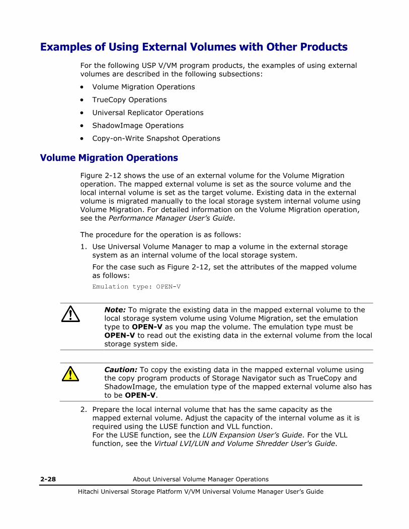
2-28 About Universal Volume Manager Operations
Hitachi Universal Storage Platform V/VM Universal Volume Manager User’s Guide
Examples of Using External Volumes with Other Products
For the following USP V/VM program products, the examples of using external volumes are described in the following subsections:
• Volume Migration Operations
• TrueCopy Operations
• Universal Replicator Operations
• ShadowImage Operations
• Copy-on-Write Snapshot Operations
Volume Migration Operations
Figure 2-12 shows the use of an external volume for the Volume Migration operation. The mapped external volume is set as the source volume and the local internal volume is set as the target volume. Existing data in the external volume is migrated manually to the local storage system internal volume using Volume Migration. For detailed information on the Volume Migration operation, see the Performance Manager User’s Guide.
The procedure for the operation is as follows:
1. Use Universal Volume Manager to map a volume in the external storage system as an internal volume of the local storage system.
For the case such as Figure 2-12, set the attributes of the mapped volume as follows: Emulation type: OPEN-V
Note: To migrate the existing data in the mapped external volume to the local storage system volume using Volume Migration, set the emulation type to OPEN-V as you map the volume. The emulation type must be OPEN-V to read out the existing data in the external volume from the local storage system side.
Caution: To copy the existing data in the mapped external volume using the copy program products of Storage Navigator such as TrueCopy and ShadowImage, the emulation type of the mapped external volume also has to be OPEN-V.
2. Prepare the local internal volume that has the same capacity as the mapped external volume. Adjust the capacity of the internal volume as it is required using the LUSE function and VLL function. For the LUSE function, see the LUN Expansion User’s Guide. For the VLL function, see the Virtual LVI/LUN and Volume Shredder User's Guide.

About Universal Volume Manager Operations 2-29
Hitachi Universal Storage Platform V/VM Universal Volume Manager User’s Guide
Note: The emulation type of the prepared internal volume must be OPEN-V.
3. Set the mapped external volume as the source volume and local storage system internal volume as the target volume.
4. Migrate the existing data in the mapped external volume to the local storage system internal volume manually using Volume Migration.
Mapping
Local Storage System
External Storage System
SourceVolume
Target Volume
Migrating data in the mapped external volume (source volume) to the internal volume (target volume) manually
using Volume Migration.
: Internal volume
: Internal volume where the external volume is mapped
: External volume
Legend
: Data migration direction
Figure 2-12 Example of the Volume Migration Operation

2-30 About Universal Volume Manager Operations
Hitachi Universal Storage Platform V/VM Universal Volume Manager User’s Guide
TrueCopy Operations
Figure 2-13 shows the use of an external volume for the TrueCopy operation. The mapped external volume is set as the S-VOL of the TrueCopy pair, and the volume in the local storage system that is connected as the multipoint control unit (MCU) is set as the P-VOL of the TrueCopy pair. For details on TrueCopy, see the TrueCopy User's Guide.
The procedure for the operation is as follows:
1. Use Universal Volume Manager to map a volume in the external storage system as an internal volume of the local storage system, which is used as remote control unit (RCU) for the TrueCopy operation.
You can select the emulation type of the mapped volume as you required. If you select the emulation type for the open system (such as OPEN-V), go on to the step 2. If you select the emulation type for the mainframe system (such as 3390-3), go on to the step 3.
2. If you set the emulation type for the open system when you map the volume, the status of the mapped volume automatically becomes Normal. However, the volume formatting processing is not executed automatically. If you need to format the mapped volume, format the volume using the VLL function.
For the volume formatting operation procedure, see the Virtual LVI/LUN and Volume Shredder User's Guide.
Go on to the step 4.
3. If you set the emulation type for the mainframe system when you map the volume, the status of the mapped volume becomes Blockade. Format the volume using the VLL function. Or if you have mapped the volume for which the data area has already been zero-formatted on the external storage system side, perform the Write to Control Blocks operation using the VLL function to restore the volume.
For the volume formatting operation procedure and the Write to Control Blocks operation procedure, see the Virtual LVI/LUN and Volume Shredder User's Guide.
Go on to the step 4.
4. Set the P-VOL and S-VOL of the TrueCopy pair.

About Universal Volume Manager Operations 2-31
Hitachi Universal Storage Platform V/VM Universal Volume Manager User’s Guide
Mapping
Local Storage System (RCU)
External Storage System
Copying data in the P-VOL of the local storage system that is connected as MCU to the S-VOL of the local storage system that is set as RCU. The S-VOL is a mapped external volume.
Local Storage System (MCU)
TrueCopy P-VOL
TrueCopyS-VOL
RCU TargetPort
Initiator Port
: Internal volume
: Internal volume where the external volume is mapped
: External volume
Legend
: Data copy direction
Figure 2-13 Example of the TrueCopy Operation

2-32 About Universal Volume Manager Operations
Hitachi Universal Storage Platform V/VM Universal Volume Manager User’s Guide
Universal Replicator Operations
Figure 2-14 shows the use of an external volume for the Universal Replicator operation. The mapped external volume is set as the S-VOL of the Universal Replicator pair, and the volume in the local storage system that is connected as the MCU is set as the P-VOL of the Universal Replicator pair. For details on Universal Replicator, see the Universal Replicator User's Guide.
The procedure for the operation is as follows:
1. Use Universal Volume Manager to map the volume in the external storage system as an internal volume of the local storage system, which is used as RCU for the Universal Replicator operation.
You can select the emulation type of the mapped volume as you required. If you select the emulation type for the open system (such as OPEN-V), go on to the step 2. If you select the emulation type for the mainframe system (such as 3390-3), go on to the step 3.
2. If you set the emulation type for the open system when you map the volume, the status of the mapped volume automatically becomes Normal. However, the volume formatting processing is not executed automatically. If you need to format the mapped volume, format the volume using the VLL function.
For the volume formatting operation procedure, see the Virtual LVI/LUN and Volume Shredder User's Guide.
Go on to the step 4.
3. If you set the emulation type for the mainframe system when you map the volume, the status of the mapped volume becomes Blockade. Format the volume using the VLL function. Or if you have mapped the volume for which the data area has already been zero-formatted on the external storage system side, perform the Write to Control Blocks operation using the VLL function to restore the volume.
For the volume formatting operation procedure and the Write to Control Blocks operation procedure, see the Virtual LVI/LUN and Volume Shredder User's Guide.
Go on to the step 4.
4. Set the P-VOL and S-VOL of the Universal Replicator pair.

About Universal Volume Manager Operations 2-33
Hitachi Universal Storage Platform V/VM Universal Volume Manager User’s Guide
Mapping
Local Storage System (RCU)
External Storage System
Copying data in the P-VOL of the local storage system that is connectedas MCU to the S-VOL of the local storage system that is set as RCU. The S-VOL is a mapped external volume.
Local Storage System (MCU)
Universal Replicator
P-VOL
Universal Replicator
S-VOL
RCU TargetPort
Initiator Port
: Internal volume
: Internal volume where the external volume is mapped
: External volume
Legend
: Data copy direction
Figure 2-14 Example of the Universal Replicator Operation

2-34 About Universal Volume Manager Operations
Hitachi Universal Storage Platform V/VM Universal Volume Manager User’s Guide
ShadowImage Operations
Figure 2-15 shows the use of an external volume for the ShadowImage operation. The mapped external volume is set as the S-VOL of the ShadowImage pair, and the local storage system internal volume is set as the P-VOL of the ShadowImage pair. For details on ShadowImage, see the ShadowImage User’s Guide.
The procedure for the operation is as follows:
1. Use Universal Volume Manager to map a volume in the external storage system as an internal volume of the local storage system.
You can select the emulation type of the mapped volume as you required. If you select the emulation type for the open system (such as OPEN-V), go on to the step 2. If you select the emulation type for the mainframe system (such as 3390-3), go on to the step 3.
2. If you set the emulation type for the open system when you map the volume, the status of the mapped volume automatically becomes Normal. However, the volume formatting processing is not executed automatically. If you need to format the mapped volume, format the volume using the VLL function.
For the volume formatting operation procedure, see the Virtual LVI/LUN and Volume Shredder User's Guide.
Go on to the step 4.
3. If you set the emulation type for the mainframe system when you map the volume, the status of the mapped volume becomes Blockade. Format the volume using the VLL function. Or if you have mapped the volume for which the data area has already been zero-formatted on the external storage system side, perform the Write to Control Blocks operation using the VLL function to restore the volume.
For the volume formatting operation procedure and the Write to Control Blocks operation procedure, see the Virtual LVI/LUN and Volume Shredder User's Guide.
Go on to the step 4.
4. Set the P-VOL and S-VOL of the ShadowImage pair.

About Universal Volume Manager Operations 2-35
Hitachi Universal Storage Platform V/VM Universal Volume Manager User’s Guide
Mapping
Local Storage System
External Storage System
ShadowImage P-VOL
Copying data in the P-VOL that is an internal volume of the local storage system to the S-VOL that is a mapped external volume.
ShadowImageS-VOL
: Internal volume
: Internal volume where the external volume is mapped
: External volume
Legend
: Data copy direction
Figure 2-15 Example of the ShadowImage Operation

2-36 About Universal Volume Manager Operations
Hitachi Universal Storage Platform V/VM Universal Volume Manager User’s Guide
Copy-on-Write Snapshot Operations
Figure 2-16 shows the use of an external volume for the Copy-on-Write Snapshot operation. The mapped external volume is set as a pool-VOL of the Copy-on-Write Snapshot pair. For details on Copy-on-Write Snapshot, see the Copy-on-Write Snapshot User’s Guide.
The procedure for the operation is as follows:
1. Use Universal Volume Manager to map a volume in the external storage system as an internal volume of the local storage system.
Caution: Set the emulation type of the volume to OPEN-V when you map the volume, because the volume with the OPEN-V emulation type can only be set as a pool-VOL of Copy-on-Write Snapshot.
2. The status of the mapped volume automatically becomes Normal. However, the volume formatting processing is not executed automatically. If you need to format the mapped volume, format the volume using the VLL function. For the volume formatting operation procedure, see the Virtual LVI/LUN and Volume Shredder User's Guide.
3. Create a pool and add the mapped external volume to that pool as a pool-VOL.
4. Set the P-VOL and S-VOL of the Copy-on-Write Snapshot pair with specifying the pool you have created at the step 3.
Mapping Copy-on-Write Snapshot
P-VOL
Creating a Copy-on-Write Snapshot pair.
Copy-on-Write Snapshot
S-VOL
Copy-on-Write Snapshot Pool-VOL
As you create a Copy-on-Write Snapshot pair, the data of the internal volume in the local storage system that is set as aP-VOL is copied to the external volume that is set as a pool-VOL
: Virtual volume (S-VOL of the Copy-on-Write Snapshot pair)
Local Storage System External Storage System
: Internal volume
: Internal volume where the external volume is mapped
: External volume
Legend
: Data copy direction
Figure 2-16 Example of the Copy-on-Write Snapshot Operation

3
Preparing for Universal Volume Manager Operations 3-1
Hitachi Universal Storage Platform V/VM Universal Volume Manager User’s Guide
Preparing for Universal Volume Manager Operations
This chapter describes the requirements and preparations for Universal Volume Manager operations.
System Requirements
Guidelines for Universal Volume Manager Operations
Installing and Uninstalling Universal Volume Manager
Starting Universal Volume Manager

3-2 Preparing for Universal Volume Manager Operations
Hitachi Universal Storage Platform V/VM Universal Volume Manager User’s Guide
System Requirements
The system requirements for Universal Volume Manager are:
• USP V/VM storage system (First storage system)
All the necessary hardware and microcode required for Universal Volume Manager operations must be installed and enabled. In this user's guide, the first storage system is called “local storage system”.
• Storage system other than the first storage system
A second storage system must be available and operated as an external storage system. The kinds of storage systems that can be used as an external storage system include the Lightning 9900V series storage system, the Thunder 9500V series storage system, the Lightning 9900C series storage system, and other similar storage systems.
• USP V/VM Storage Navigator computer (user-supplied computer)
See the Storage Navigator User’s Guide for instructions on installing and using the Storage Navigator computer.
Note: You must operate the Storage Navigator computer in Modify mode to perform Universal Volume Manager operations. Users in View mode can only view Universal Volume Manager information.
• License key for Universal Volume Manager program product
You need a license key to install Universal Volume Manager.
Storage Systems Supported as External Storage Systems
Supported storage systems that can be connected as the external storage system are shown in the following table. The table includes information on how those storage systems are referenced in this document and in the Universal Volume Manager windows.
Table 3-1 Storage Systems Available as External Storage Systems
Storage System Note
Universal Storage Platform V
Displayed by Universal Volume Manager as “USP V”.
Path Mode of the cross-subsystem paths will be Multi.
Universal Storage Platform VM
Displayed by Universal Volume Manager as “USP VM”.
Path Mode of the cross-subsystem paths will be Multi.
TagmaStore Universal Storage Platform
Displayed by Universal Volume Manager “USP”.
Path Mode of the cross-subsystem paths will be Multi.
TagmaStore Network Storage Controller
Displayed by Universal Volume Manager as “NSC”.
Path Mode of the cross-subsystem paths will be Multi.

Preparing for Universal Volume Manager Operations 3-3
Hitachi Universal Storage Platform V/VM Universal Volume Manager User’s Guide
Storage System Note
TagmaStore Adaptable Modular Storage
Displayed by Universal Volume Manager as “AMS”.
Path Mode of the cross-subsystem paths will be Single.
TagmaStore Workgroup Modular Storage
Displayed by Universal Volume Manager as “WMS”.
Path Mode of the cross-subsystem paths will be Single.
Lightning 9900V series Displayed by Universal Volume Manager as “9970V” and “9980V”.
Path Mode of the cross-subsystem paths will be Multi.
Thunder 9500V series Displayed by Universal Volume Manager as “9500V”.
Path Mode of the cross-subsystem paths will be Single.
Lightning 9900 series Lightning 9960 is displayed by Universal Volume Manager as “0400”.
Lightning 9910 is displayed by Universal Volume Manager as “0401”.
Path Mode of the cross-subsystem paths will be Multi.
A/H-6593 Displayed by Universal Volume Manager as “300”.
Path Mode of the cross-subsystem paths will be Multi.
SANRISE Universal Storage Platform
Displayed by Universal Volume Manager as “USP”.
Path Mode of the cross-subsystem paths will be Multi.
SANRISE Network Storage Controller
Displayed by Universal Volume Manager as “NSC”.
Path Mode of the cross-subsystem paths will be Multi.
SANRISE Adaptable Modular Storage
Displayed by Universal Volume Manager as “AMS”.
Path Mode of the cross-subsystem paths will be Single.
SANRISE Workgroup Modular Storage
Displayed by Universal Volume Manager as “WMS”.
Path Mode of the cross-subsystem paths will be Single.
SANRISE 9900V series Displayed by Universal Volume Manager as “9970V” and “9980V”.
Path Mode of the cross-subsystem paths will be Multi.
SANRISE 9500V series Displayed by Universal Volume Manager as “9500V”.
Path Mode of the cross-subsystem paths will be Single.
SANRISE 2000 series SANRISE 2800 is displayed by Universal Volume Manager as “0400”.
SANRISE 2200 is displayed by Universal Volume Manager as “0401”.
Path Mode of the cross-subsystem paths will be Multi.
H24000 Displayed by Universal Volume Manager as “24000”.
Path Mode of the cross-subsystem paths will be Multi.
H20000 Displayed by Universal Volume Manager as “20000”.
Path Mode of the cross-subsystem paths will be Multi.
SANRISE H12000 Displayed by Universal Volume Manager as “12000”.
Path Mode of the cross-subsystem paths will be Multi.
SANRISE H10000 Displayed by Universal Volume Manager as “10000”.
Path Mode of the cross-subsystem paths will be Multi.
SANRISE H1024/H128 Displayed by Universal Volume Manager as “1024” and “128”.
Path Mode of the cross-subsystem paths will be Multi.
SANRISE H512/H48 Displayed by Universal Volume Manager as “512” and “48”.
Path Mode of the cross-subsystem paths will be Multi.

3-4 Preparing for Universal Volume Manager Operations
Hitachi Universal Storage Platform V/VM Universal Volume Manager User’s Guide
Storage System Note
SANRISE H256 Displayed by Universal Volume Manager as “256”.
Path Mode of the cross-subsystem paths will be Multi.
XP24000 Displayed by Universal Volume Manager as “24000”.
Path Mode of the cross-subsystem paths will be Multi.
XP20000 Displayed by Universal Volume Manager as “20000”.
Path Mode of the cross-subsystem paths will be Multi.
XP12000 Displayed by Universal Volume Manager as “12000”.
Path Mode of the cross-subsystem paths will be Multi.
XP10000 Displayed by Universal Volume Manager as “10000”.
Path Mode of the cross-subsystem paths will be Multi.
XP1024/XP128 Displayed by Universal Volume Manager as “1024” and “128”.
Path Mode of the cross-subsystem paths will be Multi.
XP512/XP48 Displayed by Universal Volume Manager as “512” and “48”.
Path Mode of the cross-subsystem paths will be Multi.
XP256 Displayed by Universal Volume Manager as “256”.
Path Mode of the cross-subsystem paths will be Multi.
SVS200 Displayed by Universal Volume Manager as “SVS200”.
Path Mode of the cross-subsystem paths will be Multi.
HP StorageWorks Enterprise Virtual Array 3000/4000/5000/6000/8000
Displayed by Universal Volume Manager as “EVA”.
Path Mode of the cross-subsystem paths will be Single.
IBM storage system For the type of the supported storage system, call the Support Center.
EMC storage system For the type of the supported storage system, call the Support Center.
Fujitsu storage system For the type of the supported storage system, call the Support Center.
NEC storage system For the type of the supported storage system, call the Support Center.

Preparing for Universal Volume Manager Operations 3-5
Hitachi Universal Storage Platform V/VM Universal Volume Manager User’s Guide
Universal Volume Manager Requirements
The following table describes the Universal Volume Manager requirements.
Table 3-2 Universal Volume Manager Requirements
Item Requirement
Maximum number of ports in the connected external storage system (WWN is used as a port identification number)
1,024 per port
Maximum number of external volumes which can be connected
63,232 volumes can be connected..
4,096 volumes can be connected per port.
Note: If you use Copy-on-Write Snapshot or Dynamic Provisioning, the number of external volumes which can be connected is as follows:
Number of external volumes + Number of virtual volumes ≤ 63,232
Maximum number of mapping paths can be set for one external volume
8
Maximum capacity of an external volume
4 TB per external volume (8,589,934,592 blocks)
If you specify an external volume which is more than 4 TB you can access the data stored in the field up to 4 TB. You cannot access the data that is stored in the field over 4 TB.
Minimum capacity of an external volume
77,760 blocks (about 38 MB) per external volume. However, when the emulation type of the volume is OPEN-V, the minimum capacity becomes 96,000 blocks (about 47 MB) per external volume
Maximum number of external volume groups
16,384
Maximum number of external volumes which can be registered in one external volume group
4,096

3-6 Preparing for Universal Volume Manager Operations
Hitachi Universal Storage Platform V/VM Universal Volume Manager User’s Guide
Guidelines for Universal Volume Manager Operations
This section provides guidelines for the Universal Volume Manager operations.
Mapping Guidelines • Before mapping external volumes, make sure that external volumes are
not reserved by a host. External volumes that are reserved by a host cannot be mapped as internal volumes. If external volumes are reserved by a host, cancel the reserve settings and then map the external volumes.
• Once external volumes are mapped, do not reserve the external volumes for a host . If external volumes are reserved by a host , internal volumes to which the external volumes are mapped will be blocked .
• Make sure that an external volume is accessed only from the local storage system side once the external volume is mapped.
– Make sure that the external volume, which has been mapped as an internal volume, is not accessed from the host that is connected to the external storage system.
– Make sure that the external volume, which has been mapped as an internal volume, is not manipulated by copy function or some other functions of the external storage system.
Hosts can access the external storage system volumes that have not been mapped as the internal volumes. There is no restriction.
• Do not map multiplatform volumes of external storage systems as internal volumes.
• When an external storage system that has an ownership is connected to USP V/VM storage system, configure the cross-subsystem path to the primary controller in the external storage system as primary path.
Ownership is an exclusive right to control volumes. A controller that has an ownership is called a primary controller. If a cross-subsystem path to a controller without ownership is configured as primary path, the ownership will be transferred and it may affect the performance.

Preparing for Universal Volume Manager Operations 3-7
Hitachi Universal Storage Platform V/VM Universal Volume Manager User’s Guide
Recommended Applications according to the HDD Type
Table 3-3 and Table 3-4 show the recommended level of the application of mapped external volume according to the HDD type of the external volume.
Table 3-3 When the Emulation Type of the External Volume is for OPEN
Application HDD Type
FC SATA
Database
Online Transaction Processing (OLTP)
Not Recommended Not Recommended
File Operation from Host
(Both of Read and Write)
OK Not Recommended
File Operation from Host
(Mainly Read)
OK OK
Backup OK Recommended
Archive OK Recommended
Table 3-4 When the Emulation Type of the External Volume is for Mainframe
Application HDD Type
FC SATA
Database
Online Transaction Processing (OLTP)
Not Recommended Not Recommended
System Volumes
(Journal, Check points)
Not Recommended Not Recommended
Operation from TPF Not Supported Not Supported
File Operation from Host
(Both of Read and Write)
OK Not Recommended
File Operation from Host
(Mainly Read)
OK OK
Backup OK Recommended
Archive OK Recommended

3-8 Preparing for Universal Volume Manager Operations
Hitachi Universal Storage Platform V/VM Universal Volume Manager User’s Guide
Capacity Guidelines • When a volume, which has the capacity of 4 TB or less, in the external
storage system (external volume) is mapped with the setting of OPEN-V emulation type, the volume is defined as the internal volume that has the same capacity as the mapped external volume.
External Volume
・The capacity is 4 TB or less. ・OPEN-V emulation type
LDEV LU
Figure 3-1 Example of External Volume of 4 TB or Less
• You cannot access the data that is stored in the field over the maximum capacity of the external volume. The maximum volume capacity differs depending on the emulation type that you specify at the external volume mapping.
• When an external volume is mapped as internal volume(s) with the setting of the emulation type other than OPEN-V, the number of volumes and the volume capacity of the mapped external volume(s) depend on the capacity of the original external volume and the basic capacity of each emulation type. When an external volume is mapped with the setting of emulation type other than OPEN-V, the data management information area is required to be provided in the mapped volume. This means that the capacity that can be used after the mapping becomes smaller than the actual external volume capacity. The available capacity decreases as much capacity as the data management information area.
Figure 3-2 shows an example of the case that the original capacity of the external volume is bigger than the basic capacity of the emulation type. The emulation type is OPEN-3. Figure 3-3 shows an example of the case that the original capacity of the external volume is smaller than the basic capacity of the emulation type.

Preparing for Universal Volume Manager Operations 3-9
Hitachi Universal Storage Platform V/VM Universal Volume Manager User’s Guide
VDEV LDEV LU
6 GB
Area provided to store data management information Free Space
(The area less than the basic capacity of emulation type remains as free space)
OPEN-3
External Volume
Figure 3-2 When the External Volume Capacity is Bigger than the Basic Capacity of Specified Emulation Type (Example of the OPEN-3 emulation type)
VDEV LDEV LU External Volume
2 GB Area provided to store data management information
Figure 3-3 When the External Volume Capacity is Smaller than the Basic Capacity of Specified Emulation Type
Guidelines for Mainframe Volumes • If you plan to use the mapped external volume from the mainframe OS
(e.g., the volume is mapped with the setting of 3390-x mainframe emulation type), you need to select the external volume that consists of one LDEV or you need to adjust the capacity of the external volume to be mapped beforehand.
• If multiple LDEVs exist in one external volume and if a lot of I/Os are made to these LDEVs, the read, write commands may become timeout. When the commands become timeout, the SIM (21D2xx) is reported.

3-10 Preparing for Universal Volume Manager Operations
Hitachi Universal Storage Platform V/VM Universal Volume Manager User’s Guide
• When you use the mapped external volume from the mainframe OS, set the MIH (Missing Interrupt Handler) timer to 45 seconds (which is the recommended value).
Volume Attribute Guidelines • The external volume attributes for all the LDEVs created in an external
volume become the same. The attributes are taken over, when the LDEVs are reconfigured using the VLL function.
• The Cache Mode becomes the same for all the LDEVs in one external volume.
• The attributes that are set for the external volume originally on the external storage system side (such as the port security, the LUN security, the Volume Retention Manager attributes, and so on) are not kept, when the external volume is mapped as an internal volume. If the original attributes are required to be set, set the attributes on the mapped external volume from the local storage system side.
• For the external volume, for which the Cache Mode is set to Disable, the bind mode for the Cache Residency Manager operation is not available.
• If you use the mapped external volume for the Cache Residency Manager operation and set the bind mode, the cache of twice as much capacity as the user data is required for the Cache Residency Manager operation.
Creating LUSE Volume Guidelines • Do not combine LDEVs of multiple external volumes to create a LUSE
volume. The LDEVs in the same external volume can only be used to set the LUSE volumes.
• When you combine LDEVs of multiple external volumes to create a LUSE volume, you need to consider:
– If a LUSE volume consists of multiple external volumes and one external volume has lower performance than the other volumes, the lower performance of the volume affects the performance of the LUSE volume.
– When an external volume which is a component of a LUSE volume is blocked, data reliability of the LUSE volume will deteriorate because the LUSE volume has both accessible area and inaccessible area from a host.
– When you disconnect an external volume or resume the use of an external volume, you need to perform the operation at the same time on all the external volumes which are components of the LUSE volume.
• The mapped volumes that have different cache mode settings cannot be used to create one LUSE volume.

Preparing for Universal Volume Manager Operations 3-11
Hitachi Universal Storage Platform V/VM Universal Volume Manager User’s Guide
VMA of Data Retention Utility • If you map an external volume to which the volume management area
(VMA) of Data Retention Utility is set, you need to configure system options before performing the port discovery or volume discovery operation to validate the VMA information. Please call the Hitachi Data Systems Support Center to find out about how to configure system options (see Calling the Hitachi Data Systems Support Center).
• If you have previously mapped a TagmaStore USP volume and set the VMA of Data Retention Utility in that volume, the VMA setting is inherited when you map the volume again.
Maintenance Guidelines for an External Storage System • Before you change settings of the external storage system, you must
delete the external volume mapping. After you change settings of the external storage system, you must remap the external volume. If you do not remap the volume, the external volume cannot be used in the local storage system. The examples of external storage system settings which require the re-mapping of external volume are as follows:
– Changing WWNs of target ports which connect to the local storage system
– Changing the serial number of the external storage system
– Changing LUNs of volumes of the external storage system
– Reducing the volume capacity of the external storage system so that the volume capacity is smaller than when volume mapping was performed
Besides, re-mapping is required for Universal Volume Manager after you change external storage system settings that require modification on the host side when hosts are connected directly to a external storage system.
Before you delete the external volume mapping, make sure that the volume has no LU paths, and that the volume is not a component of any pairs (such as TrueCopy pairs).
Performance and Status Guidelines • The performance and status of the external storage system affect the Read
and Write performance of the mapped external volume. If there is a heavy load on the external storage system, the processing speed of the Read and Write operation becomes slow. In this case, the I/Os from the mainframe host may become MIH error.
• If the host connected to the local storage system issues too many I/Os to be processed by the external storage system, the commands from the host may possibly be timed out.

3-12 Preparing for Universal Volume Manager Operations
Hitachi Universal Storage Platform V/VM Universal Volume Manager User’s Guide
When the amount of I/Os from the host to the external volume exceeds the maximum amount of I/Os that the external storage system can accept, the commands from the host to the local storage system may possibly be timed out. As you configure the system using the external volumes, consider the capability for the I/O amount of the external storage system.
• When you execute the commands of the USP V/VM program products to the mapped external volume and thus too many I/Os are issued to be processed by the external storage system, the commands may possibly be timed out and an error may occur.
When the amount of I/Os from the program products to the external volume exceeds the maximum amount of I/Os that the external storage system can accept, the commands from the program products may possibly be timed out and an error may occur. As you configure the system using the external volumes, consider the capability for the I/O amount of the external storage system.
• When you use an external volume from the host, note the Path Blockade Watch time for the external volume. If the Path Blockade Watch time is longer than the timeout period of the host command, the commands from the host may possibly be timed out when the power supply is off or when an error occurs for the external storage system. If the host I/O is a significant concern, make sure that the Path Blockade Watch time of the external volume is the same as or shorter than the timeout period of the host command.
RAID Level Considerations
In the internal processing, the RAID level of the external volume is handled as RAID-1 across the board. The bar (−) is displayed on the Storage Navigator windows. The RAID level of external volumes is reported as RAID-1 when information about external storage system is reported to the higher-level device (OS).
Thunder 9500V Series Guidelines
When you use the Thunder 9500V series storage system as an external storage system, the following versions are recommended. If you use a 9500V storage system whose version is earlier than the following versions, the information about the SATA drive may not be displayed correctly.
• For Thunder 9530V, Thunder 9520V, Thunder 9570V: version 0658 or later.
• For Thunder 9580V, Thunder 9585V: version 1658 or later.

Preparing for Universal Volume Manager Operations 3-13
Hitachi Universal Storage Platform V/VM Universal Volume Manager User’s Guide
Installing and Uninstalling Universal Volume Manager
This section explains how to install and uninstall Universal Volume Manager.
Installing Universal Volume Manager
You need to install Universal Volume Manager using the license key to perform the Universal Volume Manager operations on the Storage Navigator computer.
To install the Universal Volume Manager license key:
1. Start the Storage Navigator Java applet for the desired storage system.
2. Enable the Universal Volume Manager options on the Storage Navigator computer and on each storage system.
For detailed instructions, see the Storage Navigator User’s Guide.
Uninstalling Universal Volume Manager
To uninstall Universal Volume Manager, you must cancel all the pairs and then delete the external volume mapping.
To uninstall Universal Volume Manager:
1. Start Storage Navigator, and open the Storage Navigator main window.
For instructions, see the Storage Navigator User’s Guide.
2. Delete external volume mapping.
3. Disable the Universal Volume Manager option on the Storage Navigator computer and on each storage system.
For detailed information about the un-installation procedure, see the Storage Navigator User’s Guide.

3-14 Preparing for Universal Volume Manager Operations
Hitachi Universal Storage Platform V/VM Universal Volume Manager User’s Guide
Starting Universal Volume Manager
This section explains how to start Universal Volume Manager.
To start Universal Volume Manager and display the window:
1. Start Storage Navigator, and open the Storage Navigator main window.
For instructions, see the Storage Navigator User’s Guide.
2. Click Go and then Universal Volume Manager on the menu bar of the Storage Navigator main window.
Names of the windows that you need for Universal Volume Manager operations are available in the submenu.
3. Click the name of the window you want to display.
Universal Volume Manager starts up, and the window you selected is displayed.
4. Switch to Modify mode if necessary.
For instructions, see the Storage Navigator User’s Guide.

4
Using the Universal Volume Manager GUI 4-1
Hitachi Universal Storage Platform V/VM Universal Volume Manager User’s Guide
Using the Universal Volume Manager GUI
This chapter explains the Universal Volume Manager windows. Universal Volume Manager involves the Volume Operation window, the Path Operation window and the Port Operation window. When you click the tab of the window name, the window is switched to the corresponding window.
Volume Operation Window
Path Operation Window
Port Operation Window

4-2 Using the Universal Volume Manager GUI
Hitachi Universal Storage Platform V/VM Universal Volume Manager User’s Guide
Volume Operation Window
The Volume Operation window enables you to perform the operations, such as mapping external volumes and setting cross-subsystem paths. To display the Volume Operation window, click Go, Universal Volume Manager, and then Volume Operation on the menu bar of the Storage Navigator main window.
Figure 4-1 Volume Operation Window
The Volume Operation window consists of:
• Volume Operation Tree (left of the window)
The left pane of the window is composed of a tree, and a drop-down list which is used to switch the display of the tree. The contents displayed in the list (right of the window) switch corresponding to the items selected in the tree.
• Status: Disable button or Status: Enable button (upper right of the window)
When you click Status: Disable, the button name changes to Status: Enable and you can display the external volume status in the Ext. VOL Status column in the Volume Operation list.

Using the Universal Volume Manager GUI 4-3
Hitachi Universal Storage Platform V/VM Universal Volume Manager User’s Guide
The Ext. VOL Status column does not display any status when you open the Volume Operation window, because to display the external volume status takes longer than displaying other items in the window.
Note: To update the all items in the window including the Ext. VOL Status column, make sure the button name is Status: Enable, then click File and Refresh on the menu bar of the Storage Navigator main window.
• Volume Operation List (right of the window)
Information on the local storage system and external storage system is displayed corresponding to the items selected in the tree.
The list can be sorted by the displayed items. For instance, if you want to sort the list in the order of LDEV numbers, click LDEV on the list.
The items clicked in the tree and the information displayed in the list are as follows:
Table 4-1 Volume Operation Tree
Items selected in
the list
Items displayed in the tree
(Clicked items are underlined)
Contents displayed in the list Reference
Fibre Subsystem + Product name + Path group
Information about the external storage system. The same contents are displayed when you click the product name in the tree.
Volume Operation List (When Subsystem or Product Name is Clicked)
Subsystem + Product name + Path group
Information about the external storage system. The same contents are displayed when you click the Subsystem in the tree.
Subsystem + Product name + Path group
The list of external volumes and cross-subsystem paths which are set in the selected path group.
Volume Operation List (When Path Group is Clicked)
• Operation (lower left of the window)
The name of the performed setting operation is displayed. You can check the details in the Preview dialog box by clicking the Preview button.
• Preview button (lower right of the window)
When you click Preview, the Preview dialog box is displayed and you can confirm the contents which was set in the list of the Volume Operation window. The contents displayed in the Preview dialog box have not been applied to the local storage system, yet.
• Apply button
Applies the settings in the Preview dialog box to the local storage system.
When the settings are applied successfully, they are removed from the Preview dialog box and the settings in blue and italics in the Volume Operation window is displayed normally.

4-4 Using the Universal Volume Manager GUI
Hitachi Universal Storage Platform V/VM Universal Volume Manager User’s Guide
When the settings are not applied, the error messages are displayed and the settings in blue and italics remain displayed in the Volume Operation window. To refer to the error detail, click Preview to open the Preview dialog box.
• Cancel button
Cancels all the settings in the Preview dialog box.
Volume Operation Tree
The Volume Operation tree is a tree on the left side of the Volume Operation window consisting of a tree and a drop-down list which is used to switch the display of the tree.
The Volume Operation tree consists of:
• Drop-down list
A drop-down list to switch the items displayed in the Volume Operation tree. You can select Fibre from the drop-down list as a PCB type.
• Tree
The following items are displayed in tree format. The contents displayed in the list (right of the window) switch corresponding to the items clicked in this tree. For details, see Table 4-1.
– Subsystem: The root node of the Volume Operation tree which is always displayed.
– Product name of the external volume: The product name of the external storage system whose volumes are mapped by Universal Volume Manager is displayed below Subsystem. The display format is "Vendor name: Product name (Serial number)".
– Path group: The path group set in the external storage system is displayed under the product name of the external storage system. When multiple path groups are set, the registration numbers are added after the "Path Group" (Example: Path Group 2).
• Pop-up menu
Right-click the item in the Volume Operation tree to perform the following operations from the pop-up menu.

Using the Universal Volume Manager GUI 4-5
Hitachi Universal Storage Platform V/VM Universal Volume Manager User’s Guide
Table 4-2 Pop-up Menu for the Volume Operation Tree
Items displayed in Tree
(clicked items are underlined)
Pop-up Menu Description
Subsystem + Product name + Path group
Add Volume (Auto)
Add Volume (Manual)
Displays the Configure Cross-subsystem Paths dialog box or the Add Volume (Manual) dialog box. These dialog boxes allow you to set a new path group, and add external volumes to the new path group.
Edit Policy Displays the Edit Policy dialog box. This dialog box allows you to edit the mapping policy.
Subsystem + Product name + Path group
Disconnect Subsystem
Check Paths & Restore Volume
Disconnects or reconnects the external volumes in the selected external storage system.
Subsystem + Product name + Path group
Add Volume (Auto)
Add Volume (Manual)
The Volume Discovery is executed and all the external volumes found by the Volume Discovery are displayed in the following windows.
For the Add Volume (Auto) command: Volume Operation window
For the Add Volume (Manual) command: Add Volume dialog box
Volume Operation List (When Subsystem or Product Name is Clicked)
When you click Subsystem or a product name in the Volume Operation tree, the external storage system information is displayed in the list.
Figure 4-2 Volume Operation List when Subsystem or a Product Name is Clicked
The Volume Operation list consists of:
• External Subsystem
The following items are displayed:
– Vendor: Name of the vendor.
– Product Name: Name of the storage system.
– Serial Number: Serial number of the storage system.

4-6 Using the Universal Volume Manager GUI
Hitachi Universal Storage Platform V/VM Universal Volume Manager User’s Guide
– Ext. VOL Status: Status of the operation executed to the external volume or status of the connection of the mapping path. The displayed items are shown in the following table. To check status of each LDEV in the external volume, you need to view the VLL window.
Table 4-3 Status of the External Volume Displayed in the Ext. VOL Status
Displayed Item Description
Normal The path is normal.
- The status of the mapping path is not retrieved yet. Click Status: Disable in the Volume Operation window to display the status of the mapping path.
Unknown The status of the mapping path is unknown.
Blockade The mapping path is blocked.
Warning There are mapping paths whose status is not normal. Check the status of the mapping paths in the Mapping Path Information dialog box.
Checking The processing of checking the mapping path status is in progress.
Cache Destage The writing processing of all the data in cache memory to the volume is in progress.
Disconnect Connecting to the external storage system or the external volume is intentionally stopped using the Disconnect Subsystem command or the Disconnect Volume command.
• Information Area
Information according to the contents of the External Subsystem on the Volume Operation window is displayed in the information area, as follows:
– Total Number of Ext. Subsystems: the number of external storage systems that have the mapped external volumes.
– Total Number of Ext. Volumes: the number of the mapped external volumes and the number of the external volumes that can be mapped.
• Pop-up menu
The External Subsystem does not have a pop-up menu that can be displayed.
Volume Operation List (When Path Group is Clicked)
When you click a path group in the Volume Operation tree, the external storage system information and the cross-subsystem path information is displayed in the list.

Using the Universal Volume Manager GUI 4-7
Hitachi Universal Storage Platform V/VM Universal Volume Manager User’s Guide
Figure 4-3 Volume Operation List when Path Group is Clicked
The Volume Operation list consists of:
• External Volumes
The following items are displayed:
– ExG: external volume group number and sequential number assigned to each volume in the external volume group. This is displayed in the format of “external volume group number - sequential number of volume in the group”. The sequential numbers of volumes in the group are automatically assigned by Universal Volume Manager when the external volumes are mapped.
– LDEV: LDKC:CU:LDEV number* which is assigned to the external volume. When multiple LDEVs are created in the external volume, the top LDEV number is displayed, and [...] is displayed at the end of the number.
* LDKC: Logical Disk Controller
CU: Control Unit
– Characteristic1: identification number of the external volume.
– Device: name of the storage system that is reported to the host by the external volume. The displayed items differs depending on the vendor of the storage system.

4-8 Using the Universal Volume Manager GUI
Hitachi Universal Storage Platform V/VM Universal Volume Manager User’s Guide
– Capacity (blocks): capacity of the external volume in Blocks.
– Cache Mode: displays whether the write data from the host to the external storage system is propagated synchronously (Disable) or asynchronously (Enable). Data that is not written by the host (for example, data written by ShadowImage) is asynchronously destaged to the external storage system regardless of the Cache Mode setting.
– Inflow Control: displays whether the writing operation to the cache memory is stopped (Enable) or continued (Disable) when the writing operation to the external volume is impossible.
– Path Mode: Indicates how the cross-subsystem paths work. The displayed modes of the cross-subsystem path are as follows:
– Single: For the Single mode, the only cross-subsystem path with the highest priority (primary path) is used to execute the I/O to the external volume. When an error occurred in the primary path, the path with the second highest priority is used.
– Multi: For the Multi mode, all of the cross-subsystem paths that you configured are used at the same time. The multiple paths are used to execute the I/Os to the external volume distributing the work load.
– Ext. VOL Info: information about the external volume. When the external volume is an SATA drive of the TagmaStore AMS/WMS storage system or the Thunder 9500V series storage system, “ * ” is displayed. For the operation of the SATA drive, follow the method of the TagmaStore AMS/WMS or Thunder 9500V storage system.
– Ext. VOL Status: status of the operation executed to the external volume or status of the connection of the mapping path. For the displayed status descriptions, see Table 4-3. To check status of each LDEV in the external volume, you need to view the VLL window.
– Progress: displays when the Status is Cache Destage. The progress status of destaging processing is displayed in 1 % to 99 %.
– Characteristic2: extended identification number of the external volume. This information is used for identifying volumes in the EVA storage system.
• Cross-subsystem Paths
The following items are displayed:
– Priority: Priority of the cross-subsystem paths. “1” indicates the cross-subsystem path with the highest priority.
– Port: The port number in the local storage system connecting to the external storage system.
– WWN: Identification number of the port in the external storage system.
• Pop-up Menu
Right-click a row in the External Volumes (at the top of the window) to perform the following operations from the pop-up menu.

Using the Universal Volume Manager GUI 4-9
Hitachi Universal Storage Platform V/VM Universal Volume Manager User’s Guide
Table 4-4 Pop-up Menu: External Volumes, Volume Operation Window
Pop-up Menu Description
Mapping Path Information Displays the Mapping Path Information dialog box. This dialog box allows you to refer to the list of the mapping paths set to the selected external volume.
LDEV Information Displays the LDEV Information dialog box. This dialog box allows you to refer to the emulation type and the capacity of the selected external volume.
Delete Volume Cancels the mapping of the selected external volume.
Disconnect Volume Disconnects the selected external volume.
Check Paths & Restore Volume
Reconnects the selected external volume.
Change Cache Mode Changes the cache mode set to the selected external volume.
Inflow Control Allows you to select whether to stop writing to the cache memory when it is impossible to write to the selected external volume.
Right-click a row in the Cross-subsystem Paths (at the bottom of the window) to perform the following operations from the pop-up menu.
Table 4-5 Pop-up Menu: Cross-Subsystem Paths, Volume Operation Window
Pop-up menu Description
Configure Cross-Subsystem Paths
Displays the Configure Cross-subsystem Paths dialog box. This dialog box allows you to add and delete cross-subsystem paths, and also change the priority of the selected cross-subsystem path.

4-10 Using the Universal Volume Manager GUI
Hitachi Universal Storage Platform V/VM Universal Volume Manager User’s Guide
Preview Dialog Box
The Preview dialog box allows you to check or cancel the settings that will be applied to the local storage system. To display the Preview dialog box, click Preview in the Volume Operation window, the Path Operation window, or the Port Operation window. This document uses the term "the Universal Volume Manager windows" to call these three windows.
The contents displayed in the Preview dialog box are displayed in blue italics in the list of the Universal Volume Manager windows. The contents displayed in the Preview dialog box have not been applied to the local storage system, yet. When you click Apply on the Universal Volume Manager windows, the settings in the Preview dialog box are applied to the local storage system. When the settings are applied, the contents of the Preview dialog box disappear, and the list of the Universal Volume Manager windows is displayed normally. When you click Cancel on the Universal Volume Manager windows, all the settings in the Preview dialog box are canceled.
When the settings in the Preview dialog box are not applied to the local storage system even if you click Apply on the Universal Volume Manager windows, an error message is displayed and the erroneous settings are displayed in blue and italics in the Universal Volume Manager windows. To refer to the error detail, click Preview to open the Preview dialog box.
Note: The identical error codes may be displayed for all the errors listed in the Preview dialog box depending on the type of errors occurred. In this case, check the status of settings and identify the error source.
Figure 4-4 Preview Dialog Box

Using the Universal Volume Manager GUI 4-11
Hitachi Universal Storage Platform V/VM Universal Volume Manager User’s Guide
The Preview dialog box consists of:
• Preview Area
The items set in the list of the Universal Volume Manager windows are displayed. The contents displayed in the preset area differ depending on the items set in the list of the Universal Volume Manager windows. The contents displayed in the preset area are displayed in blue italics in the list of the Universal Volume Manager windows.
• Operation Information Area
The operation information on the settings displayed in the Preview dialog box is displayed in the operation information area. Following information is displayed:
– Operation: name of the setting operation.
– Total Number of Objects in Preview: the number of settings displayed in the Preview dialog box.
• Close button
The Preview dialog box closes, and returns to the Universal Volume Manager windows.
• Pop-up menu
Right-click a row in the Preview dialog box to perform the following operations from the pop-up menu.
– Error Message: Displays the error message of the selected setting.
– Delete: Cancels the settings selected in the Preview dialog box.

4-12 Using the Universal Volume Manager GUI
Hitachi Universal Storage Platform V/VM Universal Volume Manager User’s Guide
Path Operation Window
The Path Operation window enables you to stop or resume using cross-subsystem paths. To display the Path Operation window, click Go, Universal Volume Manager, and then Path Operation on the menu bar of the Storage Navigator main window.
Figure 4-5 Path Operation Window
The Path Operation window consists of:
• Path Operation Tree (left of the window)
The left pane of the window is composed of a tree, and a drop-down list which is used to switch the display of the tree. The contents displayed in the list (right of the window) change corresponding to the items selected in the tree.
• Status: Disable button or Status: Enable button (upper right of the window)
When you click Status: Disable, the button name changes to Status: Enable and you can display the cross-subsystem path status in the Status column in the Path Operation list.

Using the Universal Volume Manager GUI 4-13
Hitachi Universal Storage Platform V/VM Universal Volume Manager User’s Guide
The Status column does not display any status when you open the Path Operation window, because to display the cross-subsystem path status takes longer than displaying other items in the window.
Note: To update the all items in the window including the Status column, make sure the button name is Status: Enable, then click File and Refresh on the menu bar of the Storage Navigator main window.
• List (right of the window)
Information on the local storage system and external storage system is displayed corresponding to the items selected in the tree.
The list can be sorted by the displayed items. For instance, if you want to sort the list in the order of port numbers, click Port on the list.
The items clicked in the tree and the information displayed in the list are as follows:
Table 4-6 Path Operation Tree
Items selected in the list
Items displayed in the tree
(Clicked items are underlined)
Contents displayed in the list Reference
Fibre -Local Subsystem
Subsystem + Port number
External ports of the local storage system.
Path Operation List (When Subsystem is Clicked)
Subsystem + Port number
Cross-subsystem paths which are set to the selected external ports of the local storage system.
The same contents are displayed when you click the WWN in the tree.
Path Operation List (When Port or WWN is Clicked)
Fibre - External Subsystem
Product name + WWN
WWNs of the external storage system.
Path Operation List (When Product Name is Clicked)
Product name + WWN
Cross-subsystem paths which are set to the selected WWN of the external storage system.
The same contents are displayed when you click the port number in the tree.
Path Operation List (When Port or WWN is Clicked)
• Operation (lower left of the window)
The name of the performed setting operation is displayed. You can check the details in the Preview dialog box by clicking the Preview button.
• Preview button (lower right of the window)
When you click Preview, the Preview dialog box is displayed and you can confirm the contents, which was set in the list of the Path Operation window. The contents displayed in the Preview dialog box have not been applied to the local storage system, yet.

4-14 Using the Universal Volume Manager GUI
Hitachi Universal Storage Platform V/VM Universal Volume Manager User’s Guide
• Apply button
Applies the settings in the Preview dialog box to the local storage system.
When the settings are applied successfully, they are removed from the Preview dialog box and the settings in blue and italics in the Path Operation window is displayed normally.
When the settings are not applied, the error messages are displayed and the settings in blue and italics remain displayed in the Port Operation window. To refer to the error detail, click Preview to open the Preview dialog box.
• Cancel button
Cancels all the settings in the Preview dialog box.
Path Operation Tree
The Path Operation tree is a tree on the left side of the Path Operation window consisting of a tree and a drop-down list which is used to switch the display of the tree.
The Path Operation tree consists of:
• Drop-down list
A drop-down list to switch the items displayed in the Path Operation tree. You can select which side to display the information on cross-subsystem paths from.
– Fibre - Local Subsystem: Displays ports in the local storage system.
– Fibre - External Subsystem: Displays ports (WWNs) in the external storage system.
• Tree
The following items are displayed in tree format. The contents displayed in the list (right of the window) change corresponding to the items clicked in this tree. For details, see Table 4-1.
When you select Fibre - Local Subsystem from the drop-down list, the following items are displayed in the tree:
– Subsystem: The root node of the Path Operation tree which is always displayed.
– Port number: The port number of the local storage system, which the port attribute is set to External, is displayed below Subsystem. One of the following icons is displayed:
– : Ports in the Standard mode.
– : Ports in the Initiator/External MIX mode.

Using the Universal Volume Manager GUI 4-15
Hitachi Universal Storage Platform V/VM Universal Volume Manager User’s Guide
When you select Fibre - External Subsystem from the drop-down list, the following items are displayed in the tree:
– Product name of the external volume: The product name of the external storage system which is connected by Universal Volume Manager is displayed as a root node. The display format is "Vendor name: Product name (Serial number)".
– WWN: The WWNs of the external storage system is displayed below the product name of the external storage system.
• Pop-up menu
The Path Operation tree does not have a pop-up menu that can be displayed.
Path Operation List (When Subsystem is Clicked)
When you click Subsystem in the Path Operation tree, the external port information which is set to the local storage system is displayed in the list.
Figure 4-6 Path Operation List when Subsystem is Clicked
The Path Operation list consists of:
• Port
The following items are displayed:
– Port: The external port of the local storage system. One of the following icons is displayed:
– : Ports in the Standard mode.
– : Ports in the Initiator/External MIX mode.
– PLI_TOV: The wait time (in seconds) of PLOGI to the external storage system when the switch is not connected. This value is automatically set by Universal Volume Manager. You cannot change the value.
– FLI_TOV: The wait time (in seconds) from the switch to FLOGI when the switch is connected. This value is automatically set by Universal Volume Manager. You cannot change the value.

4-16 Using the Universal Volume Manager GUI
Hitachi Universal Storage Platform V/VM Universal Volume Manager User’s Guide
– Margin: The additional wait time (in seconds) to FLI_TOV (FLOGI wait time) or PLI_TOV (PLOGI wait time). This value is automatically set by Universal Volume Manager. You cannot change the value. As a result, the sum of FLI_TOV time and the margin time, or the sum of PLI_TOV time and the margin time is set as a total wait time.
– Status: Status of the cross-subsystem path. Table 4-7 shows the displayed statuses.
• Pop-up menu
Right-click a row in the Path Operation list to perform the operations from the pop-up menu (Table 4-8).
Table 4-7 Status of the Cross-subsystem Path Displayed in the Status
Displayed Item
Description
Normal The cross-subsystem path is normal.
- The status of the cross-subsystem path is not retrieved yet. Click Status: Disable in the Path Operation window to display the status of the cross-subsystem path.
Unknown The status of the cross-subsystem path is unknown.
Blockade The cross-subsystem path is blocked.
Disconnect Connecting to the external storage system or the external volume is intentionally stopped using the Disconnect Subsystem command or the Disconnect Volume command.
Warning There are cross-subsystem paths whose status is not normal. Check the status of the cross-subsystem paths.
Checking The processing of checking the cross-subsystem path status is in progress.
Table 4-8 Pop-up Menu in the Path Operation List (when Subsystem is clicked)
Pop-up Menu Description
Disconnect Paths
Allows you to stop the use of the cross-subsystem paths which are connected to the selected external port of the local storage system.
Check Paths Allows you to resume using the cross-subsystem paths which are connected to the selected external port of the local storage system.

Using the Universal Volume Manager GUI 4-17
Hitachi Universal Storage Platform V/VM Universal Volume Manager User’s Guide
Path Operation List (When Product Name is Clicked)
When you click a product name in the Path Operation tree, WWN which indicate the port in the external storage system is displayed in the list.
Figure 4-7 Path Operation List when Product Name is Clicked
The Path Operation list consists of:
• WWN
The following items are displayed:
– WWN: WWN indicating the port in the external storage system that the connection setting is completed.
– QDepth: The number of Read/Write commands which can be issued (queued) to the external volume at a time.
– I/O TOV: Value specified as the time over of the I/O to the external volume.
– Path Watch: The time from when the connection of all the cross-subsystem paths to the external volume have been down to when the external volume is blocked.
– Status: Status of the cross-subsystem path. For the displayed statuses, see Table 4-7.
• Pop-up menu
Right-click a row in the Path Operation list to perform the following operations from the pop-up menu.
Table 4-9 Pop-up Menu in the Path Operation List (when Product Name is clicked)
Pop-up Menu Description
Disconnect Paths Allows you to stop the use of the cross-subsystem paths which are connected to the selected external port of the local storage system.
Check Paths Allows you to restart the use of the cross-subsystem paths which are connected to the selected external port of the local storage system.
Change WWN Parameter
Displays the Change WWN Parameter dialog box. This dialog box allows you to change the parameters on the port of the external storage system.

4-18 Using the Universal Volume Manager GUI
Hitachi Universal Storage Platform V/VM Universal Volume Manager User’s Guide
Path Operation List (When Port or WWN is Clicked)
When you click a port or WWN in the Path Operation tree, a cross-subsystem path is displayed in the list.
Figure 4-8 Path Operation List when Port or WWN is Clicked
The Path Operation list consists of:
• Cross-subsystem Paths
The following items are displayed:
– Port: external port in the local storage system.
– WWN: WWN indicating the target port in the external storage system.
– Vendor: vendor name of the external storage system.
– Product Name: product name of the external storage system.
– Serial Number: serial number of the external storage system.
– Status: Status of the cross-subsystem path. For the displayed statuses, see Table 4-7.
• Pop-up menu
When you click port or WWN in the Path Operation tree, the Path Operation list does not have a pop-up menu that can be displayed.

Using the Universal Volume Manager GUI 4-19
Hitachi Universal Storage Platform V/VM Universal Volume Manager User’s Guide
Port Operation Window
The Port Operation window enables you to check the settings of ports and set the port attributes. To display the Port Operation window, click Go, Universal Volume Manager, and then Port Operation on the menu bar of the Storage Navigator main window.
Figure 4-9 Port Operation Window
The Port Operation window consists of:
• Port Operation Tree (left of the window)
The left pane of the window is composed of a tree, and a drop-down list which is used to switch the display of the tree. The contents displayed in the list (right of the window) change corresponding to the items selected in the tree.
• Port Operation List (right of the window)
Information on the port is displayed corresponding to the items selected in the tree. The list can be sorted by the displayed items. For example, if you want to sort the list in the order of port numbers, click Port on the list.
• Operation (lower left of the window)
The name of the performed setting operation is displayed. You can check the details in the Preview dialog box by clicking the Preview button.

4-20 Using the Universal Volume Manager GUI
Hitachi Universal Storage Platform V/VM Universal Volume Manager User’s Guide
• Preview button (lower right of the window)
When you click Preview, the Preview dialog box is displayed and you can confirm the contents which was set in the list of the Port Operation window. The contents displayed in the Preview dialog box have not been applied to the local storage system, yet.
• Apply button
Applies the settings in the Preview dialog box to the local storage system.
When the settings are applied successfully, they are removed from the Preview dialog box and the settings in blue and italics in the Port Operation window is displayed normally.
When the settings are not applied, the error messages are displayed and the settings in blue and italics remain displayed in the Port Operation window. To refer to the error detail, click Preview to open the Preview dialog box.
• Cancel button
Cancels all the settings in the Preview dialog box.
Port Operation Tree
The Port Operation tree is a tree on the left side of the Port Operation window consisting of a tree and a drop-down list which is used to switch the display of the tree.
The Port Operation tree consists of:
• Drop-down list
A drop-down list to change the items displayed in the Port Operation tree. You can select Fibre from the drop-down list as a PCB type.
• Tree
The ports in the local storage system are displayed in the tree. The contents displayed in the list (right of the window) switch corresponding to the items clicked in this tree. For instance, when you click External in the tree, only the ports that port attributes are set to external are displayed in the Port Operation list.
– Subsystem: Nothing is displayed in the list when you select Subsystem. Subsystem is selected, when you display the Port Operation window.
– Port attribute: The following attributes are displayed:
– External: When you click External, the ports set to the external port are displayed in the list. The external port is the port attribute used for Universal Volume Manager. The external port does not have the High Speed mode.
– Target: When you click Target, the ports set as the target port are displayed in the list.

Using the Universal Volume Manager GUI 4-21
Hitachi Universal Storage Platform V/VM Universal Volume Manager User’s Guide
– Initiator: When you click Initiator, the ports set as the initiator port (used for TrueCopy, TrueCopy for IBM z/OS, Universal Replicator, Universal Replicator for IBM z/OS, and so on) are displayed in the list.
– RCU Target: When you click RCU Target, the ports set as the RCU target port (used for TrueCopy, TrueCopy for IBM z/OS, Universal Replicator, Universal Replicator for IBM z/OS, and so on) are displayed in the list.
– Initiator/External: When you click Initiator/External, the ports for which the Initiator/External MIX mode is set are displayed in the list.
• Pop-up menu
The Port Operation tree does not have a pop-up menu that can be displayed.
Port Operation List
When you click the items in the Port Operation tree, the port in the local storage system is displayed in the list. The list can be sorted by the displayed items. For instance, if you want to sort the list in the order of port numbers, click Port on the list.
The Port Operation list consists of:
• Port Information
The following items are displayed:
– Port: Port number. One of the following icons is displayed on the left of each port:
– : Ports in the Standard mode.
– : Ports in the High Speed mode.
– : Ports in the Initiator/External MIX mode.
– Attribute: Port attribute. The external ports are used for connecting to the external storage system. When you want to set the remote command device, you can use the port for which the Initiator/External MIX mode has been set.
– PCB Mode: The PCB mode of the port is displayed. Standard, High Speed, or MIX (for Initiator/External MIX mode) is displayed. The external ports do not have the High Speed mode. For detailed information on the PCB mode, see the LUN Manager User’s Guide.
• Information Area
The total number of ports in the Port Operation list (Total Number of Ports) is displayed.
• Pop-up Menu

4-22 Using the Universal Volume Manager GUI
Hitachi Universal Storage Platform V/VM Universal Volume Manager User’s Guide
Right-click a row in the Port Information to perform the following operations from the pop-up menu.
Table 4-10 Pop-up Menu in the Port Information
Pop-up menu Description
Change to External Allows you to change the selected port attribute to external.
Change to Target Allows you to change the selected port attribute to target.

5
Performing Universal Volume Manager Operations 5-1
Hitachi Universal Storage Platform V/VM Universal Volume Manager User’s Guide
Performing Universal Volume Manager Operations
This chapter describes setting the external volume using Universal Volume Manager.
Overview of Setting Operations
Setting Port of External Storage System
Setting Port Attribute for Local Storage System
Mapping an External Volume Automatically
Mapping an External Volume Manually
Setting the Cross-subsystem Paths
Checking the External Volume Details
Turning On or Off the Storage System
Disconnecting External Storage System or Disconnecting External Volume
Checking Connection Status and Resuming External Volume Operation
Stopping the Use of Paths to the External Volume (Disconnect Paths)
Restoring the Paths to the External Volume (Check Paths)
Changing the Cache Mode Setting of the External Volume
Changing the Inflow Control Setting of the External Volume
Changing the Port Setting of the External Storage System
Editing Mapping Policy
Deleting the External Volume Mapping

5-2 Performing Universal Volume Manager Operations
Hitachi Universal Storage Platform V/VM Universal Volume Manager User’s Guide
Overview of Setting Operations
The following figure illustrates the flow chart of the setting operations, which make external volumes usable from a host, by using Universal Volume Manager.
Set the port of the external storage system.(Setting on the external storage system site)
Set the port of the local storage system.(Port Operation window)
Map the external volume. (Volume Operation window)
Define LU paths to a host using LUN Manager.
Prepare a volume in the external storage system.(Setting on the external storage system site)
Which type of the emulation type is set for the
mapped volume, for the Open system, or the Mainframe system?
Perform one of the following operation using Virtual LVI/LUN (VLL).
- Format the volume - Perform the Write to Control Blocks operation
For Mainframe
For Open
Figure 5-1 Operations of Making External Volumes Usable from a Host
The outlined procedure of the making the external volumes usable from a host is as follows.
1. Prepare a volume in the external storage system.
2. Set the port and system parameters for the external storage system.
For the procedure, refer to the documents for your external storage system.
3. Start Storage Navigator and set the attribute of the port connecting the external storage system to External in the Port Operation window of Universal Volume Manager.
4. Map the external volume to the internal volume.
You can map external volumes automatically or manually in the Volume Operation window.

Performing Universal Volume Manager Operations 5-3
Hitachi Universal Storage Platform V/VM Universal Volume Manager User’s Guide
5. Perform the following operation according to the emulation type that you set for mapping.
– If you select the emulation type of mainframe, you need to format the volume or perform the Write to Control Blocks operation using Virtual LVI/LUN (VLL). For the procedure to format the volume and perform the Write to Control Blocks operation, see the Virtual LVI/LUN and Volume Shredder User’s Guide.
– If you select the emulation type of open-system, you need to define LU paths to a host using LUN Manager. For the procedure of defining LU paths, see the LUN Manager User’s Guide.
Setting Port of External Storage System
This section describes the procedure of setting port of the external storage system. For detailed information, refer to the documents for the external storage system you use.
To set the port of the external storage system:
1. Set the topology information according to the configuration of the connection.
2. According to the configuration, set the data transfer speed.
3. Set the system parameters.
See Connecting External Storage Systems to set the system parameters for the external storage systems.
4. Define the LUN to the port that is set.
Setting Port Attribute for Local Storage System
The attribute of the port used for Universal Volume Manager needs to be set to the external port.
Note: If the storage system is partitioned by using Virtual Partition Manager, the ports that can be set as external ports are only the ports allocated to SLPR 0.
To set the port attribute to the external port:
1. Start Storage Navigator, and open the Port Operation window.
2. Make sure that Storage Navigator is in Modify mode.
3. Right-click the port that you want to set to external port in the Port Operation list.

5-4 Performing Universal Volume Manager Operations
Hitachi Universal Storage Platform V/VM Universal Volume Manager User’s Guide
Note: To set multiple ports to external ports at a time, select and right-click all the ports you want to set.
4. Click Change to External in the pop-up menu..
In the Port Operation list, the attribute of the selected port is changed to External, and the row of the selected port is displayed in blue italics.
5. Verify the settings in the Preview dialog box.
6. Click Apply in the Port Operation window.
The settings are applied to the local storage system and the Port Operation window is displayed normally. When an error occurs, an error message is displayed. Verify the details in the Preview dialog box.
7. Set the topology information according to the configuration of the connection.
When the switch is connected, set the Fabric to Enable. When the switch is not connected, set the Fabric to Disable and set FC-AL. Set the Connection according to the configuration of the actual connection. For detailed information on setting the topology information, see the LUN Manager User’s Guide.
8. According to the configuration, set the data transfer speed.
For the data transfer speed, select Auto Negotiation setting.
Note: When you connect a TagmaStore AMS/WMS storage system, use LUN Manager to set the data transfer speed of the external port which you use to a fixed value other than the Auto. Also, set the data transfer speed of the target port of the TagmaStore AMS/WMS storage system to the fixed value according to the data transfer speed of the external port.
Mapping an External Volume Automatically
After setting the attribute of the port used for Universal Volume Manager to the external port, you are enabled to map the external volume as an internal volume.
External volumes can be mapped either automatically or manually. This section explains the automatic mapping.

Performing Universal Volume Manager Operations 5-5
Hitachi Universal Storage Platform V/VM Universal Volume Manager User’s Guide
Caution: Do not specify 01 for the LDKC number when you map a volume of which the emulation type is 3380 series except for 3380-3, 3380-3A, 3380-3B, 3380-3C. Before you apply the mapping configuration, make sure the LDKC number which is automatically assigned is 00.
Note: Before you map the external volume, check whether any application (for example, Command Control Interface) is using the command device. If there is, stop the application.
To map the external volume automatically:
1. Start Storage Navigator, and open the Volume Operation window.
2. Make sure that Storage Navigator is in Modify mode.
3. Right-click one of the following in the Volume Operation tree:
– Subsystem: Allows you to create a new path group, and add external volumes to the new path group.
– Path group: Allows you to add external volumes to the existing path group.
4. Click Add Volume (Auto) in the pop-up menu and click the desired mapping policy in the submenu.
– When you click the Subsystem in the Volume Operation tree, the Configure Cross-subsystem Paths dialog box is displayed. Go on to step 5.
– When you click the path group in the Volume Operation tree, the Volume Discovery is executed and all the external volumes found by the Volume Discovery are displayed in blue italics in the Volume Operation window. Go on to the step 7.
5. Configure cross-subsystem paths in the Configure Cross-subsystem Paths dialog box.
Configure at least two cross-subsystem paths and change the priority if necessary.
6. Click OK to close the Configure Cross-subsystem Paths dialog box.
You are returned to the Volume Operation window. The Volume Discovery is executed, and all the external volumes found by the Volume Discovery are mapped. The settings are displayed in blue italics.
7. Verify the settings in the Preview dialog box.
8. Click Apply in the Volume Operation window.
The settings are applied to the local storage system and the Volume Operation window is displayed normally. When an error occurs, an error message is displayed. Verify the details in the Preview dialog box.

5-6 Performing Universal Volume Manager Operations
Hitachi Universal Storage Platform V/VM Universal Volume Manager User’s Guide
Mapping an External Volume Manually
After setting the attribute of the port used for Universal Volume Manager to the external port, you are enabled to map the external volume as an internal volume.
Caution: Do not specify 01 for the LDKC number when you map a volume of which the emulation type is 3380 series except for 3380-3, 3380-3A, 3380-3B, 3380-3C.
Note: Before you map the external volume, check whether any application (for example, Command Control Interface) is using the command device. If there is, stop the application.
To map the external volume manually:
1. Start Storage Navigator, and open the Volume Operation window.
2. Make sure that Storage Navigator is in Modify mode.
3. Right-click one of the following in the Volume Operation tree:
– Subsystem: Allows you to create a new path group, and add external volumes to the new path group
– Path group: Allows you to add external volumes to the existing path group.
4. Click Add Volume (Manual) in the pop-up menu and click the desired mapping policy in the submenu.
– When you click the Subsystem in the Volume Operation tree, the Configure Cross-subsystem Paths dialog box is displayed. Go on to step 5.
– When you click the path group in the Volume Operation tree, the Volume Discovery is executed and the Add Volume dialog box is displayed. Go on to the step 7.
5. Configure cross-subsystem paths in the Configure Cross-subsystem Paths dialog box.
Configure at least two cross-subsystem paths and change the priority if necessary.
6. Click OK to close the Configure Cross-subsystem Paths dialog box.
The Volume Discovery is executed and all the external volumes found by the Volume Discovery are displayed in the Add Volume dialog box.
The Add Volume dialog box displays a list of all the external volumes which can be mapped to the local storage system. To map these volumes, set the external volume parameter or the LDEV number as explained in the following steps.

Performing Universal Volume Manager Operations 5-7
Hitachi Universal Storage Platform V/VM Universal Volume Manager User’s Guide
7. In the Add Volume dialog box, right-click the external volume that you want to map.
Note: You can select multiple external volumes to make the same settings to them at a time. When you map LDEVs, you can select the multiple external volumes which have the same emulation type.
8. Click each command in the pop-up menu and make the settings in the resulting dialog box. Execute the operations in the following order (a and then b).
– a) The Set External Volume Parameter command: Allows you to configure the external volume parameters. After you configure parameters, click OK to close the dialog box.
– b) Configure the LDKC:CU:LDEV number to the LDEVs in the external volume. After you configure the number, click OK to close the dialog box. The LDEV Mapping (Auto) command: Allows you to specify the LDEV number to the first LDEV in the external volume. The rest of LDEVs are automatically allocated to the subsequent LDEV number. The LDEV Mapping (Manual) command: Allows you to specify the LDEV number to all the LDEVs in the external volume. Both commands allow you to specify the interval between LDEV numbers.
When you close the dialog box, the Add Volume dialog box is displayed.
9. In the Add Volume dialog box, make the settings to all the volumes you want to map (repeat step 7 and step 8).
Note: Delete the external volume that you do not want to map in the Add Volume dialog box. To delete the external volume, right-click the external volume and click Delete in the pop-up menu.
10. Click OK to close the Add Volume dialog box.
– When the SSID setting is required, the SSID dialog box is displayed. Go on to step 11.
– When the SSID setting is not required, the Volume Operation window is displayed. Go on to step 15.
11. In the SSID dialog box, Right-click an LDEV for which SSID is not specified, and then click SSID in the pop-up menu.
The Set SSID dialog box is displayed.
12. In the Set SSID dialog box, select a value from the SSID drop-down list and click OK.
The selected value is displayed in the SSID dialog box.
13. In the SSID dialog box, make the settings to all the LDEVs that you need to set SSID to (repeat step 11 and step 12).

5-8 Performing Universal Volume Manager Operations
Hitachi Universal Storage Platform V/VM Universal Volume Manager User’s Guide
14. Click OK to close the SSID dialog box.
You are returned to the Volume Operation window. The settings are displayed in blue italics.
15. Verify the settings in the Preview dialog box.
16. Click Apply in the Volume Operation window.
The settings are applied to the local storage system and the Volume Operation window is displayed normally. When an error occurs, an error message is displayed. Verify the details in the Preview dialog box.
Add Volume Dialog Box
The Add Volume dialog box allows you to view the external volume parameter or LDEV number which are configured to the LDEVs in the external volume. The Add Volume dialog box is automatically displayed when you click the Add Volume (Manual) command in the Volume Operation window.
The Add Volume dialog box displays the list of the external volumes which can be mapped to the local storage system. If you want to map the external volume, you need to configure the external volume parameter and the LDEV number. The parameter which you have not configured is displayed with " - ". To configure such parameter, click the external volume having the parameter which you have not configured, and open the other dialog boxes from the Add Volume dialog box. Delete the external volume if the Add Volume dialog box contains the external volume that you do not want to map.
Figure 5-2 Add Volume Dialog Box

Performing Universal Volume Manager Operations 5-9
Hitachi Universal Storage Platform V/VM Universal Volume Manager User’s Guide
The Add Volume dialog box consists of:
• List
– Characteristic1: identification number of the external volume.
– ExG: external volume group number and its sequential number.
– Emulation Type: emulation type of the external volume.
– LDEV: LDKC:CU:LDEV number which is assigned to the external volume.
– Number of LDEVs: number of LDEVs which are actually created in the external volume.
– SLPR/CLPR: SLPR and CLPR used to access the external volume. This is displayed when the cache memory is partitioned using Virtual Partition Manager.
– Cache Mode: displays whether the write data from the host to the external storage system is propagated synchronously (Disable) or asynchronously (Enable).
– Inflow Control: displays if the writing operation to the cache memory is stopped (Enable) or continued (Disable) when the writing operation to the external volume is impossible.
– Path Mode: indicates how the cross-subsystem paths work.
– Device: product name reported to the host by the external volume.
– Ext. VOL Info: information about the external volume.
– Capacity (blocks): capacity of the external volume in Blocks.
– Characteristic2: extended identification number of the external volume.
• OK button
Saves the settings and closes the dialog box.
• Cancel button
Cancels the settings and closes the dialog box.
• Pop-up Menu
Right-click a row in the Add Volume dialog box to perform the following operations from the pop-up menu.
Table 5-1 Pop-up Menu in the Add Volume dialog box
Pop-up Menu Description
Set External Volume Parameter
Displays the Set External Volume Parameter dialog box. This dialog box allows you to set the parameters.
LDEV Mapping (Auto)
Displays the LDEV Mapping (Auto) dialog box. This dialog box allows you to specify the LDEV number to the first LDEV in the external volume.
LDEV Mapping (Manual)
Displays the LDEV Mapping (Manual) dialog box. This dialog box allows you to specify the LDEV number to all the LDEVs in the external volume.
Delete Allows you to delete the external volume from the Add Volume dialog box.

5-10 Performing Universal Volume Manager Operations
Hitachi Universal Storage Platform V/VM Universal Volume Manager User’s Guide
Set External Volume Parameter Dialog Box
The Set External Volume Parameter dialog box allows you to set the external volume parameter. The Set External Volume Parameter dialog box is displayed when you right-click the external volume in the Add Volume dialog box and click the Set External Volume Parameter in the pop-up menu.
Figure 5-3 Set External Volume Parameter Dialog Box
The Set External Volume Parameter dialog box consists of:
• ExG (1-16384)
Group number of the connected external volume. You need to specify the number using decimal numbers from 1 to 16384. “E” displayed outside of the text box is the capital letter of the external volume group.
• Emulation Type
You can select the emulation type of the mapped external volume from the drop-down list.
If you want to map the external volume as an open system volume, you need to first decide the emulation type for the mapped volume, OPEN-V or other than OPEN-V. If you want to map the external volume as an open system volume with the emulation type other than OPEN-V, select the Except OPEN-V check box.
– As you clear the Except OPEN-V check box, OPEN-V and available mainframe emulation types are displayed in the drop-down list.
– As you select the Except OPEN-V check box, the emulation types for the open system other than OPEN-V are also displayed in the drop-down list.

Performing Universal Volume Manager Operations 5-11
Hitachi Universal Storage Platform V/VM Universal Volume Manager User’s Guide
• Number of LDEVs
You can select the maximum number of LDEVs which can be created in the external volume when you map the external volume. The number of LDEVs that can be created in the external volume is different corresponding to the capacity supported by the emulation type specified in the Emulation Type. The number of LDEVs which are actually created in the external volume is displayed in the Number of LDEVs column in the Add Volume dialog box after you set this parameter in the Set External Volume Parameter dialog box.
• Cache mode
Cache mode specifies if the write data from the host is propagated synchronously (Disable) or asynchronously (Enable) to the external storage system. Data that is not written by the host (for example, data written by ShadowImage) is asynchronously destaged to the external storage system regardless of the Cache Mode setting.
If you set Disable, the bind mode of Cache Residency Manager cannot be set.
• Inflow Control
Inflow Control specifies if the writing operation to the cache memory is stopped (Enable) or continued (Disable) when the writing operation to the external volume is impossible.
• CLPR
When the cache memory is partitioned using Virtual Partition Manager, you can select CLPR used for accessing to the mapped external volume from the drop-down list. The number of SLPR to which the selected CLPR belongs is displayed at the right of the drop-down list. However, when the emulation type for the mainframe is selected in Emulation Type, you can only select CLPR that belongs to SLPR number 0.
• OK button
Saves the settings and closes the dialog box.
• Cancel button
Cancels the settings and closes the dialog box.
LDEV Mapping (Auto) Dialog Box
The LDEV Mapping (Auto) dialog box allows you to specify the LDEV number only to the first LDEV in the external volume. If you specify the LDEV number to the first LDEV, the subsequent LDEV numbers are automatically assigned for the rest of LDEVs.

5-12 Performing Universal Volume Manager Operations
Hitachi Universal Storage Platform V/VM Universal Volume Manager User’s Guide
Figure 5-4 LDEV Mapping (Auto) Dialog Box
The LDEV Mapping (Auto) dialog box consists of:
• SLPR Limited
To restrict the CU in the CU drop-down list to the CU which belongs to the SLPR, select the Limited. To display all the CU in the CU drop-down list without any restriction, select the Unlimited. By default, the Limited is selected.
• LDKC drop-down list
You can select the LDKC number of the local storage system to which you want to map the external volume.
• CU drop-down list
You can select the CU number of the local storage system to which you want to map the external volume. When you select Limited in the SLPR Limited, the selection range is limited to CU which belongs to the SLPR.
• Interval drop-down list
You can select the interval of the LDKC:CU:LDEV number for mapping each volume. The LDEV number is set to each LDEV with the interval that you specified in this drop-down list.

Performing Universal Volume Manager Operations 5-13
Hitachi Universal Storage Platform V/VM Universal Volume Manager User’s Guide
• LDEV Map
LDEV map allows you to allocate the LDEV number to each LDEV by clicking cells in a table.
Each cell in the LDEV map represents an internal volume. In the LDEV map, the horizontal scale indicates tens place digit of the LDEV number, and the vertical scale indicates ones place digit of the LDEV number. Select a cell for the internal volume on the LDEV map, the selected cell turns to blue, and the LDEV number which the cell indicates is defined to the LDEV. The defined internal volume is grayed out, and undefined internal volumes to be mapped are displayed in white.
• OK button
Saves the settings and closes the dialog box.
• Cancel button
Cancels the settings and closes the dialog box.
• Pop-up menu
This dialog box does not have a pop-up menu that can be displayed.
LDEV Mapping (Manual) Dialog Box
The LDEV Mapping (Manual) dialog box allows you to specify the LDEV number to all the LDEVs in the external volume.
Figure 5-5 LDEV Mapping (Manual) Dialog Box

5-14 Performing Universal Volume Manager Operations
Hitachi Universal Storage Platform V/VM Universal Volume Manager User’s Guide
The LDEV Mapping (Manual) dialog box consists of:
• List
– ExG
The external volume group number of the connected external volume, which you specified in the Set External Volume Parameter dialog box, is displayed.
– LDKC:CU:LDEV
You use the LDKC:CU:LDEV with the LDEV map for assigning the LDEV number. You can either map an LDEV number to each LDEV one by one, or map a numbers to multiple LDEVs at once.
The LDKC:CU:LDEV shows the LDKC numbers, CU numbers, and LDEV numbers of the external volumes mapped as internal volumes. “ - ” indicates that the external volumes are not mapped as internal volumes.
To assign an LDEV number to an LDEV, select one or more external volume whose LDEV number is “ - ” in the LDKC:CU:LDEV, and select one cell in the LDEV map.
When you select two or more external volumes in the LDKC:CU:LDEV, the other cells are automatically added to match the number of external volumes that you previously selected in the LDKC:CU:LDEV. When Interval is set, mapping is performed in intervals of that number.
• Pop-up menu
This dialog box does not have a pop-up menu that can be displayed.
Other items are same as the LDEV Mapping (Auto) dialog box.
SSID Dialog Box
The SSID dialog box allows you to set the SSID to the LDEVs in the external volume. The USP V/VM storage system assigns a SSID which identifies each group of LDEV number. If the LDEVs that you created do not have SSID, you need to assign one using the SSID dialog box. The SSID dialog box is displayed during the mapping operation when the SSID setting is required.

Performing Universal Volume Manager Operations 5-15
Hitachi Universal Storage Platform V/VM Universal Volume Manager User’s Guide
Figure 5-6 SSID Dialog Box
The SSID dialog box consists of:
• SLPR drop-down list
When the storage system is partitioned using Virtual Partition Manager, use the SLPR drop-down list.
If you select the SLPR Limited check box and select the SLPR number in the SLPR drop-down list, only the SSIDs that can be used for the selected SLPR can be set in the Set SSID dialog box. If you do not select the SLPR Limited check box, you can set the SSID from all the unused SSIDs regardless of the selected SLPR number.
• List
– LDEV Boundary
The range of LDEVs in the selected external volume is displayed.
– SSID
The SSIDs allocated to each LDEV are displayed. If SSID is not set, " - " is displayed.
• OK button
Saves the settings and closes the dialog box.
• Cancel button
Cancels the settings and closes the dialog box.
• Pop-up Menu
Right-click a row in the SSID column to execute the Set SSID command in the pop-up menu. The Set SSID command allows you to set the SSID to the selected LDEV. When you click the Set SSID, the following dialog box is displayed.

5-16 Performing Universal Volume Manager Operations
Hitachi Universal Storage Platform V/VM Universal Volume Manager User’s Guide
Figure 5-7 Set SSID Dialog Box
SSID (0004-FFFE): Select the SSID from the SSID drop-down list. You can select the value for an SSID from 0x0004 to 0xFFFE.
– If you have selected the SLPR Limited check box on the SSID dialog box, only the SSIDs that can be used in SLPR selected on the SSID dialog box are displayed in the drop-down list.
– If you have not selected the SLPR Limited check box on the SSID dialog box, all of the unused SSIDs are displayed in the drop-down list regardless of the selected SLPR.
Example: How to Map LDEVs Automatically
For instance, you map two external volumes which have the same emulation type, and create two LDEVs in each external volume.
To assign the number starting with 00:01:01 with 255 intervals to total four LDEVs that you created:
1. Select the two external volumes and right-click them in the Add Volume dialog box, and then click the LDEV Mapping (Auto) in the pop-up menu.
The LDEV Mapping (Auto) dialog box is displayed.
2. Configure the starting LDEV number and interval as follows:
– LDKC: 00
– CU: 01
– Interval: 255
– LDEV map: Select the cell in the row 1 and column 00.
3. Click OK.
LDEV numbers are automatically assigned as follows:
– the first LDEV: 00:01:01
– the second LDEV: 00:02:01
– the third LDEV: 00:03:01
– the fourth LDEV: 00:04:01
However, the Add Volume dialog box displays only the LDEV number assigned for the first LDEV of each external volume. In this case, 00:01:01... and 00:03:01... are displayed in the Add Volume dialog box.

Performing Universal Volume Manager Operations 5-17
Hitachi Universal Storage Platform V/VM Universal Volume Manager User’s Guide
Example: How to Map LDEVs Manually
This example shows how to map two external volumes that have the same emulation type, and create two LDEVs in each external volume.
To assign the desired number to total four LDEVs that you created:
1. Select the two external volumes and right-click them in the Add Volume dialog box, and then click the LDEV Mapping (Manual) in the pop-up menu.
The LDEV Mapping (Manual) dialog box is displayed.
2. Click the LDEV to which you want to assign an LDEV number in the LDKC:CU:LDEV column on the left of the LDEV Mapping (Manual) dialog box.
3. Select the desired LDKC number and the desired CU number to the specified LDEV from the drop-down list on the right of the LDEV Mapping (Manual) dialog box.
4. Click the cell of the desired LDEV number in the LDEV map on the right of the LDEV Mapping (Manual) dialog box.
The selected cell turns blue and the assigned LDEV number is displayed in the LDKC:CU:LDEV column.
5. Make the settings to all the LDEVs in the LDKC:CU:LDEV column (repeat step 2 through step 4).
6. Click OK.
The specified numbers are assigned to the LDEVs. However, the Add Volume dialog box displays only the LDEV number assigned for the first LDEV of each external volume.

5-18 Performing Universal Volume Manager Operations
Hitachi Universal Storage Platform V/VM Universal Volume Manager User’s Guide
Figure 5-8 Example of LDEV Mapping (Manual) Dialog Box
Note: You can also assign contiguous LDEV numbers to LDEVs using this dialog box. To assign contiguous LDEV numbers to LDEVs, select multiple LDEVs at step 2, and specify the starting LDEV number at step 3 and 4. You can set Interval if necessary.
Setting the Cross-subsystem Paths
You need to configure the cross-subsystem path from the internal volume to the external volume before using the external volume mapped as an internal volume.
You can configure the cross-subsystem path when you map the external volume as the internal volume. You can also add or change the cross-subsystem paths after the mapping operation is completed. To configure the cross-subsystem paths, use the Configure Cross-subsystem Paths dialog box.

Performing Universal Volume Manager Operations 5-19
Hitachi Universal Storage Platform V/VM Universal Volume Manager User’s Guide
Caution: You cannot delete all the current cross-subsystem paths to substitute newly-added cross-subsystem paths for them in one operation. To replace all the current cross-subsystem paths with newly-added cross-subsystem paths, you need to perform more than two operations and leave at least one current cross-subsystem path setting when you perform the first operation.
Configure Cross-subsystem Paths Dialog Box
The Configure Cross-subsystem Paths dialog box allows you to configure cross-subsystem paths. This dialog box is automatically displayed when you add a volume to a new path group using the Add Volume (Auto) command or the Add Volume (Manual) command. You can also open this dialog box by clicking the Configure Cross-subsystem Paths command in the Volume Operation window.
You can change the priority, add and delete the cross-subsystem path in the Configure Cross-subsystem Paths dialog box.
The Volume Operation window displays only the external storage system which you have configured the mapping. However, the Configure Cross-subsystem Paths dialog box displays all the external storage system connected to the local storage system even without the mapping configuration. To update the dialog box, click the Port Discovery button in the upper right of the dialog box.
Figure 5-9 Configure Cross-subsystem Paths Dialog Box

5-20 Performing Universal Volume Manager Operations
Hitachi Universal Storage Platform V/VM Universal Volume Manager User’s Guide
The Configure Cross-subsystem Paths dialog box consists of:
• Available Paths (Upper part of the dialog box)
The following three panes are displayed from the left,
– The left pane displays the external storage systems connected to the local storage system.
– Vendor: vendor name.
– Product Name: product name.
– Serial Number: serial number of the product.
– The middle pane displays external ports of the local storage system, which connects to the external storage system that you clicked in the left pane. One of the following icons is displayed for each port:
– Port: external port of the local storage system. One of the following icons is displayed:
: Ports in the Standard mode. : Ports in the Initiator/External MIX mode.
– The right pane displays WWN of the external storage system that the port attribute is set to Target. The WWN which connects to the port that you clicked in the middle pane is displayed out of the WWN of the external storage system which you clicked in the left pane.
– WWN: Identification number of the port in the external storage system.
• Port Discovery button (Upper right of the dialog box)
Allows you to update information displayed in the Available Paths or display the information on all the external storage system connected to the local storage system even without the mapping configuration. When you click Port Discovery, the Port Discovery dialog box is displayed.
Figure 5-10 Port Discovery Dialog Box

Performing Universal Volume Manager Operations 5-21
Hitachi Universal Storage Platform V/VM Universal Volume Manager User’s Guide
The Port Discovery dialog box displays the list of the external ports in the local storage system. When you click the external port in the list, WWNs of the external storage system connected to the clicked external port are searched for, and that the Available Paths in the Configure Cross-subsystem Paths dialog box is updated.
• Selected Paths (Lower part of the dialog box)
The cross-subsystem paths that you have added in the Available Paths are displayed.
– Priority: Priority of the cross-subsystem paths connecting to the external volume. “1” indicates the path with the highest priority.
– Port: Port of the local storage system that the port attribute is set to External.
– WWN: WWN of the external storage system that the port attribute is set to Target.
• OK button
Saves the settings and closes the dialog box.
• Cancel button
Cancels the settings and closes the dialog box.
• Pop-up Menu
Right-click a row in the Configure Cross-subsystem Paths dialog box to perform the following operations from the pop-up menu.
Table 5-2 Pop-up Menu in the Configure Cross-Subsystem Paths dialog box
Right-clicked Area
Pop-up Menu
Description
WWN in the Available Paths
Add Allows you to add cross-subsystem paths.
Selected Paths Delete Allows you to delete the selected cross-subsystem path.
Raise Priority
Allows you to raise the priority of the selected cross-subsystem path.
Lower Priority
Allows you to lower the priority of the selected cross-subsystem path.
Configuring Cross-subsystem Path
You can configure the cross-subsystem path using the Configure Cross-subsystem Paths dialog box. This section explains the procedure to add a cross-subsystem path to an existing path group. To create a new path group and configure cross-subsystem paths, you need to operate the mapping operation.

5-22 Performing Universal Volume Manager Operations
Hitachi Universal Storage Platform V/VM Universal Volume Manager User’s Guide
To add the cross-subsystem path to an existing path group:
1. Start Storage Navigator, and open the Volume Operation window.
2. Make sure that Storage Navigator is in Modify mode.
3. Click the path group that you want to add a cross-subsystem path in the Volume Operation tree.
4. Right-click the cross-subsystem path in Cross-subsystem Paths in the Volume Operation list.
5. Click Configure Cross-subsystem Paths in the pop-up menu.
The Configure Cross-subsystem Paths dialog box is displayed.
6. In the Available Paths, click the following three items, and then right-click the WWN in the WWN.
– External storage system: Click the external storage system.
– Port: Click the external port of the local storage system which is the starting point of the cross-subsystem path.
– WWN: Click the WWN of the external storage system which is the ending point of the cross-subsystem path.
Note: When the external storage system or the WWN that you want to choose is not displayed in the dialog box, you can update the information by clicking the Port Discovery button, selecting the port which connects to the WWN, and then clicking OK.
7. Click Add in the pop-up menu.
The cross-subsystem path is added to the Selected Paths with the selected information. Configure more than two cross-subsystem paths for one path group. Change the priority or delete unnecessary cross-subsystem paths if necessary.
8. Click OK to close the Configure Cross-subsystem Paths dialog box.
You are returned to the Volume Operation window. The settings are displayed in blue and italics.
9. Verify the settings in the Preview dialog box.
10. Click Apply in the Volume Operation window.
The settings are applied to the local storage system and the Volume Operation window is displayed normally. When an error occurs, an error message is displayed. Verify the details in the Preview dialog box.

Performing Universal Volume Manager Operations 5-23
Hitachi Universal Storage Platform V/VM Universal Volume Manager User’s Guide
Figure 5-11 Pop-up Menu of Configure Cross-subsystem Paths Dialog Box
Changing the Configured Cross-subsystem Path Priority
To change the cross-subsystem path priority, use the Raise Priority command and the Lower Priority command displayed in the Configure Cross-subsystem Paths dialog box.
The following is an example of procedure to make the cross-subsystem path to the currently used path by raising the priority of the cross-subsystem path:
1. Start Storage Navigator, and open the Volume Operation window.
2. Make sure that Storage Navigator is in Modify mode.
3. Click the path group to which the cross-subsystem path belongs in the Volume Operation tree.
4. Right-click the cross-subsystem path in Cross-subsystem Paths in the Volume Operation list.
5. Click Configure Cross-subsystem Paths in the pop-up menu.
The Configure Cross-subsystem Paths dialog box is displayed.
6. Right-click the cross-subsystem path that you want to change the priority of in the Selected Paths in the Configure Cross-subsystem Paths dialog box.
7. Click Raise Priority in the pop-up menu
The row of the selected path switches with the one row above.

5-24 Performing Universal Volume Manager Operations
Hitachi Universal Storage Platform V/VM Universal Volume Manager User’s Guide
8. Repeat the operation of the Raise Priority command until the row of the selected path is displayed in the head of the Selected Paths list and its Priority column changes to “1”.
When the Priority column changes to “1”, it means the cross-subsystem path is set as the usually used one (primary path).
9. Click OK to close the Configure Cross-subsystem Paths dialog box.
You are returned to the Volume Operation window. The settings are displayed in blue and italics.
10. Verify the settings in the Preview dialog box.
11. Click Apply in the Volume Operation window.
The settings are applied to the local storage system and the Volume Operation window is displayed normally. When an error occurs, an error message is displayed. Verify the details in the Preview dialog box.
Canceling the Cross-subsystem Path Configuration
You can cancel the configuration of the cross-subsystem path using the Configure Cross-subsystem Paths dialog box.
To cancel the cross-subsystem path configuration:
1. Start Storage Navigator, and open the Volume Operation window.
2. Make sure that Storage Navigator is in Modify mode.
3. Click the path group to which the cross-subsystem path belongs in the Volume Operation tree.
4. Right-click the cross-subsystem path in Cross-subsystem Paths in the Volume Operation list.
5. Click Configure Cross-subsystem Paths in the pop-up menu.
6. In the Configure Cross-subsystem Paths dialog box, right-click the cross-subsystem path that you want to cancel the configuration in the Selected Paths.
7. Click Delete in the pop-up menu
The configuration of the selected cross-subsystem path is canceled, and the cross-subsystem path is deleted from the Cross-subsystem Paths.
8. Click OK to close the Configure Cross-subsystem Paths dialog box.
You are returned to the Volume Operation window. The settings are displayed in blue and italics.
9. Verify the settings in the Preview dialog box.
10. Click Apply in the Volume Operation window.
The settings are applied to the local storage system and the Volume Operation window is displayed normally. When an error occurs, an error message is displayed. Verify the details in the Preview dialog box.

Performing Universal Volume Manager Operations 5-25
Hitachi Universal Storage Platform V/VM Universal Volume Manager User’s Guide
Changing the Cross-subsystem Path
To change the cross-subsystem path, cancel the current cross-subsystem path, and configure another cross-subsystem path as a new cross-subsystem path.
Replacing All the Cross-subsystem Paths with Newly-added Cross-subsystem Paths
This section explains how to change all the current cross-subsystem paths to newly-added cross-subsystem paths with an example.
Figure 5-12 shows the overview of the operation and the status of the cross-subsystem paths. When you delete the current cross-subsystem paths (A and B) and add new cross-subsystem paths (C and D), you cannot delete both the current cross-subsystem paths (A and B) in one operation because at least one current path which functions normally has to be configured. In this case, you need to delete the cross-subsystem path A and add the cross-subsystem path C, and then apply the setting. After that, you need to delete the cross-subsystem path B and add the cross-subsystem path D.
Legend
:Internal volume where external volume is mapped
Internal Volume
ExternalVolume
A B C D
:Cross-subsystem path whose status is Normal
:Cross-subsystem path whose status is Disconnect
:Added cross-subsystem path
Internal Volume
ExternalVolume
A B C D
Internal Volume
ExternalVolume
A B C D
Internal Volume
ExternalVolume
A B C D
Internal Volume
ExternalVolume
A B C D
Execute the Disconnect Paths commandon the cross-subsystem path A.
Delete the cross-subsystem path A, add the cross-subsystem path C, and then apply the setting.
Execute the Disconnect Paths commandon the cross-subsystem path B.
Delete the cross-subsystem path B, add the cross-subsystem path D, and then apply the setting.
Figure 5-12 Overview of Operation to Replace All the Current Cross-subsystem Paths with Newly-added Cross-subsystem Paths

5-26 Performing Universal Volume Manager Operations
Hitachi Universal Storage Platform V/VM Universal Volume Manager User’s Guide
To replace all the current cross-subsystem paths (A and B) with newly-added cross-subsystem paths (C and D):
1. Execute the Disconnect Paths command on the cross-subsystem path A.
2. Disconnect the cable which the cross-subsystem path A uses, and connect the cable which the cross-subsystem path C uses.
3. Cancel the configuration of the cross-subsystem path A, and add the cross-subsystem path C.
4. Click Apply to apply the settings of the cross-subsystem paths A and C.
5. Make sure the status of the cross-subsystem path C is Normal.
At this point, the cross-subsystem paths B and C are configured as normal paths.
Take the following steps to delete the cross-subsystem path B and add the cross-subsystem path D.
6. Execute the Disconnect Paths command on the cross-subsystem path B.
7. Disconnect the cable which the cross-subsystem path B uses, and connect the cable which the cross-subsystem path D uses.
8. Cancel the configuration of the cross-subsystem path B, and add the cross-subsystem path D.
9. Click Apply to apply the settings of the cross-subsystem paths B and D.
10. Make sure the status of the cross-subsystem path D is Normal.
Checking the External Volume Details
You can check the details on the mapped external volume using the LDEV Information dialog box, and the details on the mapping path using the Mapping Path Information dialog box.
To check the external volume details:
1. Start Storage Navigator, and open the Volume Operation window.
2. Click the path group in the Volume Operation tree.
3. Right-click the external volume that you want to check in the Volume Operation list.
4. Click the following command in the pop-up menu.
– LDEV information: Displays the LDEV Information dialog box.
– Mapping Path Information: Displays the Mapping Path Information dialog box.
5. Verify the details in the displayed dialog box.
6. Click Close to close the displayed dialog box.
You are returned to the Volume Operation window.

Performing Universal Volume Manager Operations 5-27
Hitachi Universal Storage Platform V/VM Universal Volume Manager User’s Guide
LDEV Information Dialog Box
The LDEV Information dialog box displays the information on the LDEVs created in the external volumes. Each row displays one LDEV information.
Figure 5-13 LDEV Information Dialog Box
The LDEV Information dialog box consists of:
• List
– LDKC:CU:LDEV: The LDKC:CU:LDEV number of the LDEVs created in the external volume.
– Emulation Type: The emulation type of the external volume set when it was mapped.
– Capacity: Capacity of the external volume is displayed. When the emulation type of the mapped external volume is for the open system, the capacity is displayed in Blocks. When the emulation type of the mapped external volume is for the mainframe system, the capacity is displayed in Cylinder.
• Close button
Closes the LDEV Information dialog box.
• Pop-up menu
The LDEV Information dialog box does not have a pop-up menu that can be displayed.

5-28 Performing Universal Volume Manager Operations
Hitachi Universal Storage Platform V/VM Universal Volume Manager User’s Guide
Mapping Path Information Dialog Box
The Mapping Path Information dialog box displays the information on the mapping paths which connect the internal volume and the external volume.
Figure 5-14 Mapping Path Information Dialog Box
The Mapping Path Information dialog box consists of:
• List
– Priority: Priority of the mapping path. “1” indicates the mapping path with the highest priority.
– Port: The port number in the local storage system connecting to the external storage system.
– WWN: Identification number of the port in the external storage system.
– LUN: LU number set to the external volume.
– Status: Status of the mapping path. Table 5-3 lists and describes the status terms that are displayed on the Mapping Path Information dialog box.
• Close button
Close the Mapping Path Information dialog box.
• Pop-up menu
The Mapping Path Information dialog box does not have a pop-up menu that can be displayed.
Table 5-3 Status of the Mapping Paths in the Mapping Path Information Dialog Box
Displayed Item Description
Normal The mapping path is normal.
- The status of the mapping path is not retrieved yet. Click Status: Disable in the Volume Operation window to display the status of the mapping path.
Unknown The status of the mapping path is unknown.

Performing Universal Volume Manager Operations 5-29
Hitachi Universal Storage Platform V/VM Universal Volume Manager User’s Guide
Displayed Item Description
Blockade The mapping path is blocked.
External device setting changed
The setting of the external storage system has been changed. For example, the path definition was deleted, or the external storage system itself was replaced by another device.
LDEV size reduced
The setting of the volume capacity of the external storage system has been changed (the volume capacity was reduced).
Not ready The reply from the external storage system was NOT READY.
Illegal request The reply from the external storage system was ILLEGAL REQUEST.
Command aborted
The reply from the external storage system was ABORTED COMMAND.
Busy The external storage system is in the BUSY status.
LDEV reserved The external storage system is in the Reserve status.
Response error The external storage system is in the blocked status because of an abnormal reply.
Initiator port The port attribute of the external storage system has been changed to the initiator port.
Unknown port The port attribute of the external storage system is unknown.
Cannot detect port
The path has been removed or the port of the external storage system cannot be found.
Internal error The program error occurred. Or there is a logical contradiction.
Timeout The processing was retried because an abnormal reply was returned, however, the processing has been timed out.
Standby The port of the external storage system is standing by. The port status is normal but cannot receive I/O.
Target error Port failures, such as controller blockade are detected on the external storage system side.
Checking The processing of checking the mapping path status is in progress.
Disconnect Connection to the external storage system or the external volume is intentionally stopped using the Disconnect Subsystem command or the Disconnect Volume command.
Unavailable The reply from the external storage system was Unavailable. The external storage system demands to change the connected port. Once the status becomes Unavailable, the primary path is changed to the alternate path that is in the Standby status. When the primary path has been changed, the status of the path becomes Normal.
Backoff The reply from the external storage system was Backoff. The status of the path is waiting for recovery because a temporary error has occurred in the volume of the external storage system. Even if the status of the primary path becomes this status, the primary path is not changed to the alternate path immediately. After the error recovery, the status becomes Normal. If the status cannot be recovered from the error, the path status is changed to the other status.

5-30 Performing Universal Volume Manager Operations
Hitachi Universal Storage Platform V/VM Universal Volume Manager User’s Guide
Turning On or Off the Storage System
This section describes the procedures to turn on or off the power supply of the local storage system and the external storage system after the Universal Volume Manager operation has been started.
This section includes the following procedures, and uses ShadowImage as an example:
• Commands for Turning On or Off Only the External Storage System
• Turning On or Off Only the External Storage System
• Turning On or Off Only the Local Storage System
• Turning On or Off Both Storage Systems
When you turn on or off the power supply of only external storage system, you need to execute the Universal Volume Manager commands.
Cautions: • When you want to turn off both the local storage system and the external
storage system, you first need turn off the local storage system, and then turn off the external storage system.
• When you want to turn on both the local storage system and the external storage system, you first need to turn on the external storage system, and then turn on the local storage system.
Commands for Turning On or Off Only the External Storage System
When you turn on or off the power supply of only external storage system while the power supply of the local storage system keeps on, you need to execute the following Universal Volume Manager commands.
The commands used for the procedure are as follows:
• Disconnect Subsystem command
The Disconnect Subsystem command should be executed when the external storage system is maintained or stopped on purpose. When the Disconnect Subsystem command is executed, the acceptance of the host I/O to the external volume that is mapped as the internal volume is stopped. Then all the data that should belong to the external volume is written to the external volume from the cache memory of the local storage system (all the data is destaged).

Performing Universal Volume Manager Operations 5-31
Hitachi Universal Storage Platform V/VM Universal Volume Manager User’s Guide
Note: When you want to perform the same processing of the Disconnect Subsystem command on individual volume, you can use the Disconnect Volume command. If you want to delete the external volume mapping individually, you first need to execute the Disconnect Volume command and then the Delete Volume command.
• Check Paths & Restore Volume command
The Check Paths & Restore Volume command checks if the defined information about the mapped external volume and the actual external volume status match. If the external volume can be used as the mapped volume as the result of the check, the external volume is set to accept the I/Os, and you can continue using the external volume as a mapped volume.
The Check Paths & Restore Volume command can be used to restore the external volume, which is set to reject the host I/O by the Disconnect Subsystem command or the Disconnect Volume command, as the mapped volume. The Check Paths & Restore Volume command can be executed for both the whole storage system and for the individual volume.
If an error occurs in the path, firstly remove the error in the path to make the path restorable, and then execute the Check Paths & Restore Volume command.
Note: When the Check Paths & Restore Volume command is executed and the external volume is ready to be restored as the mapped volume, the external volume is set to accept the I/Os and you can resume using the external volume as a mapped volume. However, if the external volume is not ready to be restored, the external volume status remains blocked.
Turning On or Off Only the External Storage System
To turn off the power supply of the external storage system (to turn off on purpose):
1. Stop the read or write I/O to the external volume that is mapped as a local storage system internal volume and is contained in the external storage system that you want to turn off.
2. Execute the Disconnect Subsystem command for the external storage system that you want to turn off.
The additional I/O to the external volume is stopped and all the data in the local cache memory is written in the external volume (all the data is destaged).
3. Perform other operations that are required before turning off the local storage system, if there is some.
4. Turn off the power supply of the external storage system.

5-32 Performing Universal Volume Manager Operations
Hitachi Universal Storage Platform V/VM Universal Volume Manager User’s Guide
Cautions: • After you have executed the Disconnect Subsystem command, but you need to use the mapped external volume again, execute the Check Paths & Restore Volume command. • To turn on the power supply of the external storage system to restart from the turned off status:
– Turn on the external storage system that contains the external volume, which is mapped as an internal volume.
– Execute the Check Paths & Restore Volume command of the Universal Volume Manager.
• When the external storage system is turned off after the Disconnect Subsystem command is executed, you cannot access the mapped external volume from the local storage system as you just turn the external storage system on. It is necessary to execute the Check Paths & Restore Volume command to resume using the mapped external volume. The Check Paths & Restore Volume command checks the defined information and the actual status of the external volume mapped as an internal volume. If the external volume is ready to be used as a mapped volume, the volume is set to accept the I/Os and you can resume using the volume as a mapped volume.
Turning On or Off Only the Local Storage System
To turn off the power supply of the local storage system (to turn off on purpose):
1. Stop the read or write I/O to the external volume that is mapped as a local storage system internal volume.
2. Perform other operations that are required before turning off the local storage system, if there is some.
3. Turn off the power supply of the local storage system.
Note: As you turn off the power supply of the local storage system, all the data, which is for the external volume, in the local cache memory is written in the external volume (all the data is destaged).

Performing Universal Volume Manager Operations 5-33
Hitachi Universal Storage Platform V/VM Universal Volume Manager User’s Guide
To turn on the power supply of the local storage system to restart from the turned off status:
1. Turn on the external storage system that contains the external volume, which is mapped as an internal volume.
2. Turn on the power supply of the local storage system.
Cautions: • When the local storage system is turned off after the Disconnect Subsystem command is executed, you cannot access the mapped external volume from the local storage system as you just turn the local storage system on. It is necessary to execute the Check Paths & Restore Volume command to resume using the mapped external volume. The Check Paths & Restore Volume command checks if the defined information and the actual status of the external volume mapped as an internal volume match. If the external volume is ready to be used as a mapped volume, the volume is set to accept the I/Os and you can resume using the volume as a mapped volume. • When the Disconnect Subsystem command or the Disconnect Volume command is executed and all the data in the cache memory is written to the external volume, the displayed information for Ext. VOL Status in the Volume Operation window becomes Disconnect.
Turning On or Off Both Storage Systems
This section explains how to turn on or off the power supply of the local and external storage systems, and uses ShadowImage as an example.
To turn off the power supply of both storage systems:
1. Stop the read or write I/O to the local storage system. All read and write I/Os with fibre channel connections should be stopped.
2. Split all ShadowImage pairs (pairsplit operation). For details on the pairsplit operation, see the ShadowImage User’s Guide.
3. Turn off the power supply of the local storage system.
Caution: Make sure that the power supply of the local storage system is completely off and then go on to the next step.
4. Turn off the power supply of the external storage system.
Cautions: Make sure that the power supply of the external storage system is completely off.

5-34 Performing Universal Volume Manager Operations
Hitachi Universal Storage Platform V/VM Universal Volume Manager User’s Guide
To turn on the power supply of both storage systems:
1. Turn on the power supply of the external storage system.
Caution: Make sure that the power supply of the external storage system is completely on and then go on to the next step.
2. Turn on the power supply of the local storage system.
Caution: Make sure that the power supply of the local storage system is completely on and then go on to the next step.
3. Resynchronize all ShadowImage pairs (pairresync operations).
For details on the pairresync operation, see the ShadowImage User’s Guide.
4. Start the read or write I/O to the local storage system.
All read and write I/Os with fibre channel connections should be started.
Disconnecting External Storage System or Disconnecting External Volume
The Disconnect Subsystem command and the Disconnect Volume command allow you to disconnect the external volume. You need to disconnect the external volume(s), for example, before you turn the power supply off of the local storage system or the external storage system for maintenance, or before you delete the external volume mapping.
As you execute the Disconnect Subsystem command or the Disconnect Volume command, the acceptance of the host I/O to the mapped external volume is stopped and all the data in the cache memory is written into the external volume (all the data is destaged).
The settings of the mapping are preserved, even though the external volume is disconnected using the Disconnect Subsystem command or the Disconnect Volume command. Therefore, you can resume using the external volume as a mapped volume with the former settings, even though once you have disconnected the external volume.

Performing Universal Volume Manager Operations 5-35
Hitachi Universal Storage Platform V/VM Universal Volume Manager User’s Guide
The following table describes operations that are required before disconnecting external volumes.
Table 5-4 Operations Required before Disconnecting External Volumes
If External Volume is Used in this way
This Operation is Required
I/Os to the external volume from the open system host are in progress.
Stop the host I/Os to the volume and un-mount from the host.
The host I/Os to the specified volume are forcibly stopped if you disconnect an external volume when I/Os from the open system host are in progress.
The external volume is online from the mainframe host.
Stop the host I/Os to the volume and perform the Vary Offline operation.
The external volume includes the LDEVs that are set as the pair of the copy program products*.
Delete the pairs.
However, you can disconnect external volumes without deleting pairs when the ShadowImage pair status is PSUE or when the ShadowImage for IBM z/OS pair status is Suspend.
The external volume includes the LDEVs that are registered to a pool for Copy-on-Write Snapshot as pool volumes.
Change the status of the Copy-on-Write Snapshot pair to PAIR.
The external volume includes the LDEVs that are registered to a pool for Dynamic Provisioning as pool volumes.
Perform the following operations on all the Dynamic Provisioning volumes (V-VOLs) that are associated with a pool to which the external volume is registered.
Stop the use of the Dynamic Provisioning volumes.
Block the Dynamic Provisioning volumes by using the VLL function for blocking volumes.
The external volume includes the LDEVs for which the migration processing of Volume Migration is in progress.
Delete the migration plans.
*Note: The copy program products includes ShadowImage, ShadowImage for IBM z/OS, Universal Replicator, Universal Replicator for IBM z/OS, TrueCopy, TrueCopy for IBM z/OS, and Copy-on-Write Snapshot.

5-36 Performing Universal Volume Manager Operations
Hitachi Universal Storage Platform V/VM Universal Volume Manager User’s Guide
Cautions: The cautions on the Disconnect Subsystem command and the Disconnect Volume command are as follows: • After you have executed the Disconnect Subsystem command or the
Disconnect Volume command, click the Refresh command ( ) on the Storage Navigator main window to update the information, and check the current progress status.
• When the Disconnect Subsystem command or the Disconnect Volume command is executed, the displayed information for Ext. VOL Status in the Volume Operation window becomes Cache Destage. Even if there is no data left in the cache memory, the displayed status remains as Cache Destage, until the processing of the Disconnect Subsystem command or the Disconnect Volume command has been completed.
• When the Disconnect Subsystem command or the Disconnect Volume command is executed and all the data in the cache memory is written to the external volume, the displayed information for Ext. VOL Status in the Volume Operation window becomes Disconnect.
Disconnecting All External Volumes (Disconnect Subsystem)
To disconnect all the external volumes in the external storage system at once:
1. Start Storage Navigator, and open the Volume Operation window.
2. Make sure that Storage Navigator is in Modify mode.
3. Right-click the product name that you want to disconnect in the Volume Operation tree.
4. Click Disconnect Subsystem in the pop-up menu.
The settings are displayed in blue and italics.
5. Verify the settings in the Preview dialog box.
6. Click Apply in the Volume Operation window.
The settings are applied to the local storage system and the Volume Operation window is displayed normally. When an error occurs, an error message is displayed. Verify the details in the Preview dialog box.
Caution: If you want to access the external storage system after you have executed the Disconnect Subsystem command, you need to execute the Check Paths & Restore Volume command.
Disconnecting an Individual External Volume (Disconnect Volume)
To disconnect an individual external volume:
1. Start Storage Navigator, and open the Volume Operation window.
2. Make sure that Storage Navigator is in Modify mode.

Performing Universal Volume Manager Operations 5-37
Hitachi Universal Storage Platform V/VM Universal Volume Manager User’s Guide
3. Click the product name in the Volume Operation tree.
4. Right-click the external volume that you want to change in the Volume Operation list.
5. Click Disconnect Volume in the pop-up menu.
The settings are displayed in blue and italics.
6. Verify the settings in the Preview dialog box.
7. Click Apply in the Volume Operation window.
The settings are applied to the local storage system and the Volume Operation window is displayed normally. When an error occurs, an error message is displayed. Verify the details in the Preview dialog box.
Caution: If you want to access the external storage system after you have executed the Disconnect Volume command, you need to execute the Check Paths & Restore Volume command.
Checking Connection Status and Resuming External Volume Operation
You can resume external volume operation by executing the Check Paths & Restore Volume command in the following cases:
• The Check Paths & Restore Volume command is required to be executed to resume using the disconnected external volume using the Disconnect Subsystem command or the Disconnect Volume command.
• When the errors occur in all the cross-subsystem paths, the local storage system makes the status of external volume to Blockade. In this case, execute the Check Paths & Restore Volume command.
If the status of the external volume cannot be restored even though the Check Paths & Restore Volume command is executed, restore the path to the external storage system as described in Troubleshooting. Then execute the Check Paths & Restore Volume command to make the external volume in the Blockade status usable.
• When the Check Paths & Restore Volume command is executed for the disconnected external volume for which the mapping settings are preserved, the defined mapping setting and the current status of the external volume are compared and checked if the settings match the actual status. The path status and all other mapping configuration definitions are checked. If the external volume can be resumed as a mapped volume as a result of the checking processing, the volume status is set to be available for the I/O operation.

5-38 Performing Universal Volume Manager Operations
Hitachi Universal Storage Platform V/VM Universal Volume Manager User’s Guide
Caution: After you have executed the Check Paths & Restore Volume command, check the current progress status. To refresh the displayed information, make sure the button name on the upper right of the Storage Navigator main window is Status: Enable, and click File and Refresh on the menu bar of the Storage Navigator main window.
Note: When the Check Paths & Restore Volume command is executed and the external volume is ready to be restored as the mapped volume, the external volume is set to accept the I/Os and you can resume using the external volume as a mapped volume. However, if the external volume is not ready to be resumed, the status of the disconnected volume remains as Blockade.
Resuming All External Volumes (Check Paths & Restore Volume)
To resume all the external volumes in the external storage system at once:
1. Start Storage Navigator, and open the Volume Operation window.
2. Make sure that Storage Navigator is in Modify mode.
3. Right-click the product name that you want to resume connection in the Volume Operation tree.
4. Click Check Paths & Restore Volume in the pop-up menu.
The settings are displayed in blue and italics.
5. Verify the settings in the Preview dialog box.
6. Click Apply in the Volume Operation window.
The Ext. VOL Status in the Volume Operation window changes to Checking. When the checking processing of mapping path status is completed, and the external storage system can be resumed, the Ext. VOL Status changes to Normal. If the external storage system can not be resumed, the Ext. VOL Status changes to Blockade.
Resuming an Individual External Volume (Check Paths & Restore Volume)
To resume an individual external volume:
1. Start Storage Navigator, and open the Volume Operation window.
2. Make sure that Storage Navigator is in Modify mode.
3. Click the path group in the Volume Operation tree.
4. Right-click the external volume that you want to resume connection in the Volume Operation list.
5. Click Check Paths & Restore Volume in the pop-up menu.

Performing Universal Volume Manager Operations 5-39
Hitachi Universal Storage Platform V/VM Universal Volume Manager User’s Guide
The settings are displayed in blue and italics.
6. Verify the settings in the Preview dialog box.
7. Click Apply in the Volume Operation window.
The Ext. VOL Status in the Volume Operation window changes to Checking. When the checking processing of mapping path status is completed, and the external volume can be resumed, the Ext. VOL Status changes to Normal. If the external volume can not be resumed, the Ext. VOL Status changes to Blockade.
Stopping the Use of Paths to the External Volume (Disconnect Paths)
You use the Disconnect Paths command to prepare for stopping the use of the cross-subsystem path. For example, when you want to maintain one of the cross-subsystem paths, you can stop the specified cross-subsystem path while the local storage system is still connected to the external volume. To resume the use of the cross-subsystem path which is stopped by the Disconnect Paths command, use the Check Paths command.
Note: The Disconnect Paths command is not for the actual disconnection of the cross-subsystem path to the external volume. You need to confirm that some normal cross-subsystem paths to the external volume is set, other than the cross-subsystem path for which you plan to execute the Disconnect Paths command.
To stop the use of the paths to the external volume:
1. Start Storage Navigator, and open the Path Operation window.
2. Make sure that Storage Navigator is in Modify mode.
3. Select one of the following from the drop-down list above the Path Operation tree.
– Fibre - Local Subsystem: Displays the ports in the local storage system. Select Fibre - Local Subsystem to stop the use of all the cross-subsystem paths connected to the specified port in the local storage system.
– Fibre - External Subsystem: Displays the WWNs in the external storage system. Select Fibre - External Subsystem to stop the use of all the cross-subsystem paths connected to the specified WWNs (ports) in the external storage system.
4. Click Subsystem or the product name in the Path Operation tree.
5. Right-click the port or WWN that you want to stop the use of in the Path Operation list.
6. Click Disconnect Paths in the pop-up menu.
The settings are displayed in blue and italics.

5-40 Performing Universal Volume Manager Operations
Hitachi Universal Storage Platform V/VM Universal Volume Manager User’s Guide
7. Verify the settings in the Preview dialog box.
8. Click Apply in the Path Operation window.
The settings are applied to the local storage system and the Path Operation window is displayed normally. When an error occurs, an error message is displayed. Verify the details in the Preview dialog box.
Restoring the Paths to the External Volume (Check Paths)
You use the Check Paths command to resume using the cross-subsystem path which was stopped by the Disconnect Paths command.
Note: The path has to be in a status that can be restored.
To restore the path to the external volume:
1. Start Storage Navigator, and open the Path Operation window.
2. Make sure that Storage Navigator is in Modify mode.
3. Select one of the following from the drop-down list above the Path Operation tree.
– Fibre - Local Subsystem: Displays the ports in the local storage system. Select Fibre - Local Subsystem to restore all the cross-subsystem paths connected to the specified port in the local storage system.
– Fibre - External Subsystem: Displays the WWNs in the external storage system. Select Fibre - External Subsystem to restore all the cross-subsystem paths connected to the specified WWNs (ports) in the external storage system.
4. Click Subsystem or the product name in the Path Operation tree.
5. Right-click the port or WWN that you want to restore in the Path Operation list.
6. Click Check Paths in the pop-up menu.
The settings are displayed in blue and italics.
7. Verify the settings in the Preview dialog box.
8. Click Apply in the Path Operation window.
The settings are applied to the local storage system and the Path Operation window is displayed normally. When an error occurs, an error message is displayed. Verify the details in the Preview dialog box.

Performing Universal Volume Manager Operations 5-41
Hitachi Universal Storage Platform V/VM Universal Volume Manager User’s Guide
Changing the Cache Mode Setting of the External Volume
You can change the cache mode of the external volume in the Volume Operation window. To change the cache mode of the external volume, right-click the external volume, click the Change Cache Mode in the pop-up menu, and then click Enable or Disable. Data that is not written by the host (for example, data written by ShadowImage) is asynchronously destaged to the external storage system regardless of the Cache Mode setting.
Check the following before changing the cache mode of the external volume.
• Whether the volume is not set as a volume which constitutes a part of a LUSE volume.
When it is set as a volume which constitutes a part of a LUSE volume, the cache mode setting should be same among all volumes which constitutes a LUSE volume.
• Whether the bind mode of Cache Residency Manager is not set.
When the bind mode is set, you cannot change the cache mode from Enable to Disable. To change the cache mode to Disable, cancel the setting for Cache Residency Manager or change the cache residency mode to the priority mode.
• Whether the volume is not registered to a pool.
When a volume is registered to a pool as a pool volume, the cache mode setting should be the same among all the pool volumes in the pool.
• Whether the volume is not a remote command device.
When the volume is a remote command device, you cannot change the cache mode from Disable to Enable.
To change the cache mode of the external volume:
1. Start Storage Navigator, and open the Volume Operation window.
2. Make sure that Storage Navigator is in Modify mode.
3. Click the path group in the Volume Operation tree.
4. Right-click the external volume that you want to change in the Volume Operation list.
5. Click Change Cache Mode in the pop-up menu and click Enable or Disable in the submenu.
The settings are displayed in blue and italics.
6. Verify the settings in the Preview dialog box.
7. Click Apply in the Volume Operation window.
The settings are applied to the local storage system and the Volume Operation window is displayed normally. When an error occurs, an error message is displayed. Verify the details in the Preview dialog box.

5-42 Performing Universal Volume Manager Operations
Hitachi Universal Storage Platform V/VM Universal Volume Manager User’s Guide
Changing the Inflow Control Setting of the External Volume
You can change the inflow control setting of the external volume in the Volume Operation window. To change the inflow control setting of the external volume, right-click the external volume, click the Inflow Control in the pop-up menu, and then click Enable or Disable.
To change the inflow control setting of the external volume:
1. Start Storage Navigator, and open the Volume Operation window.
2. Make sure that Storage Navigator is in Modify mode.
3. Click the path group in the Volume Operation tree.
4. Right-click the external volume that you want to change in the Volume Operation list.
5. Click Inflow Control in the pop-up menu and click Enable or Disable in the submenu.
The settings are displayed in blue and italics.
6. Verify the settings in the Preview dialog box.
7. Click Apply in the Volume Operation window.
The settings are applied to the local storage system and the Volume Operation window is displayed normally. When an error occurs, an error message is displayed. Verify the details in the Preview dialog box.
Changing the Port Setting of the External Storage System
You can change the setting of the port of the external storage system in the Path Operation window. For changing the setting of the port, use the Change WWN Parameter dialog box.
Cautions: • If the default setting has no problem, use the default setting as it is. • For the volume used in usual I/O, set I/O TOV within 15 seconds. • For changing the setting, match the value to the recommended value of
the external storage system.
To change the port setting of the external storage system:
1. Start Storage Navigator, and open the Path Operation window.
2. Make sure that Storage Navigator is in Modify mode.
3. Select Fibre - External Subsystem from the drop-down list above the Path Operation tree.
4. Click the product name in the Path Operation tree.

Performing Universal Volume Manager Operations 5-43
Hitachi Universal Storage Platform V/VM Universal Volume Manager User’s Guide
5. Right-click the WWN that you want to change the setting in the Path Operation list.
6. Click Change WWN Parameter in the pop-up menu.
The Change WWN Parameter dialog box is displayed.
7. Change the set parameter of the selected port on the Change WWN Parameter dialog box.
8. Click OK to close the Change WWN Parameter dialog box.
You are returned to the Path Operation window. The selected items are displayed in blue and italics.
9. Verify the settings in the Preview dialog box.
10. Click Apply in the Path Operation window.
The settings are applied to the local storage system and the Path Operation window is displayed normally. When an error occurs, an error message is displayed. Verify the details in the Preview dialog box.
Change WWN Parameter Dialog Box
Figure 5-15 Change WWN Parameter Dialog Box
The Change WWN Parameter dialog box consists of:
• QDepth (2-128): The number of Read/Write commands which can be issued (queued) to the external volume at a time. The value that can be set are from 2 to 128. The default value is 8.
• I/O TOV (5-240): Value specified as the time over of the I/O to the external volume. The value that can be set are 5 to 240 (in second). The default value is 15.
• Path Blockade Watch (5-180): The time from when the connection of all the paths to the external volume have been down to when the external volume is blocked. The commands from the host are accepted until the time set for this parameter has passed. After the time set for this parameter has passed, the path status becomes Blockade. The value that can be set are from 5 to 180 (seconds). The default value is 10.

5-44 Performing Universal Volume Manager Operations
Hitachi Universal Storage Platform V/VM Universal Volume Manager User’s Guide
Editing Mapping Policy
You choose mapping policy when you map an external volume as an internal volume using the Add Volume commands. This section explains how to edit the default mapping policy.
To edit the mapping policy:
1. Start Storage Navigator, and open the Volume Operation window.
2. Make sure that Storage Navigator is in Modify mode.
3. Right-click Subsystem in the Volume Operation tree:
4. Click Edit Policy in the pop-up menu.
The Edit Policy dialog box is displayed.
5. Click Default Policy in the Pattern.
6. Edit the settings in the Policy.
7. Click Close to close the Edit Policy dialog box.
The mapping policy is changed, and then the Volume Operation window is displayed.
Edit Policy Dialog Box
The Edit Policy dialog box allows you to edit the mapping policy.
Figure 5-16 Edit Policy Dialog Box
The Edit Policy dialog box consists of:
• Pattern: Mapping policies. Default Policy is prepared.
• Policy: The content of the selected mapping policy is displayed.
– Emulation Type: The emulation type of the external volume. To select an emulation type other than OPEN-V, select the Except OPEN-V check box and select the emulation type from the drop-down list.

Performing Universal Volume Manager Operations 5-45
Hitachi Universal Storage Platform V/VM Universal Volume Manager User’s Guide
– CLPR: CLPR used for accessing to the mapped volume when the cache memory is partitioned using Virtual Partition Manager.
– SLPR: SLPR that the selected CLPR belongs to. However, when the emulation type for the mainframe is selected in Emulation Type, you can only select CLPR that belongs to SLPR number 0.
– Cache mode: displays if the write I/O from the host is propagated synchronously (Disable) or asynchronously (Enable) to the external storage device.
– Inflow Control: displays the writing operation to the cache memory is stopped (Enable) or continued (Disable) when the writing operation to the external volume is impossible.
– Number of LDEVs: maximum number of LDEVs to be created in the external volume.
– Auto Discovery of Ports: displays whether to search for the WWN connected to all the external ports (Enable) or to search for the WWN connected to only the external port which you specify (Disable). If you set Enable, Port Discovery is automatically executed before the Configure Cross-subsystem Paths dialog box is displayed.
• Close button
Close the Edit Policy dialog box.
• Pop-up menu
The Edit Policy dialog box does not have a pop-up menu that can be displayed.
Deleting the External Volume Mapping
You can start the operation of deleting the external volume mapping from the Volume Operation window. To delete the mapping of the external volume, click the Delete Volume command in the pop-up menu displayed in the Volume Operation window. Though you can delete the setting of mapping for an internal volume and an external volume using the Delete Volume command, you cannot delete data in the external volume. You cannot delete data in the internal volume either.
Check the following before deleting the external volume mapping.
• Whether the execution of any application (for example, Command Control Interface) that is using the command device is in progress or not.
If the execution of any application that is using the command device is in progress, stop the application.
• Whether the Disconnect Subsystem command or the Disconnect Volume command is executed.

5-46 Performing Universal Volume Manager Operations
Hitachi Universal Storage Platform V/VM Universal Volume Manager User’s Guide
All the data in the cache memory must be written into the mapped external volume using the Disconnect Subsystem command or the Disconnect Volume command.
• Whether the volume is set as a volume which configures a LUSE volume.
When it is set as a volume which configures a LUSE volume, you cannot delete the external volume mapping.
• Whether an LU path is set.
When an LU path is set to the mapped volume, you cannot delete the external volume mapping.
• Whether the volume is set to configure the TrueCopy pair, Universal Replicator pair, ShadowImage pair, or Copy-on-Write Snapshot pair.
When the volume is set to configure the TrueCopy pair, Universal Replicator pair, ShadowImage pair, or Copy-on-Write Snapshot pair, you cannot delete the external volume mapping.
• Whether the volume is set as a reserved volume for ShadowImage or Volume Migration.
When the volume is set as the reserved volume for ShadowImage or Volume Migration, you cannot delete the external volume mapping.
• Whether the volume is set as a pool-VOL.
When the volume is set as a pool-VOL, you cannot delete the external volume mapping.
To delete the external volume mapping:
1. Start Storage Navigator, and open the Volume Operation window.
2. Make sure that Storage Navigator is in Modify mode.
3. Click the path group in the Volume Operation tree.
4. Right-click the external volume that you want to delete in the Volume Operation list.
5. Click Delete Volume in the pop-up menu.
The settings are displayed in blue and italics.
6. Verify the settings in the Preview dialog box.
7. Click Apply in the Volume Operation window.
8. When a message asking if you have performed the Disconnect operation is displayed, click Yes if you have already performed the Disconnect Subsystem command or the Disconnect Volume command. Click No if you have not performed the Disconnect Subsystem command or the Disconnect Volume command yet.
– If you click Yes, the setting is applied to the local storage system, and the external volume where the mapping is deleted is removed from the Volume Operation list.

Performing Universal Volume Manager Operations 5-47
Hitachi Universal Storage Platform V/VM Universal Volume Manager User’s Guide
– If you click No, a message asking if you want to execute the Delete Volume operation without writing the data in the cache memory into the external volume is displayed. Click OK if you want to execute the Delete Volume operation without writing the data in the cache memory into the external volume. Click Cancel if you want to cancel the operation. As you click OK, the setting is applied to the local storage system, and the external volume where the mapping is deleted is removed from the Volume Operation list.
Note: As you click OK, the Delete Volume operation will be performed, however, the data in the cache memory that is not written to the volume is not guaranteed.
When an error occurs, an error message is displayed. Verify the details in the Preview dialog box.
Note: The operation may not be performed if some parts of the local storage system are blocked. In this case, restore the blocked parts of the local storage system first, and then retry the operation.

5-48 Performing Universal Volume Manager Operations
Hitachi Universal Storage Platform V/VM Universal Volume Manager User’s Guide

6
Using Spreadsheets for Universal Volume Manager Operations 6-1
Hitachi Universal Storage Platform V/VM Universal Volume Manager User’s Guide
Using Spreadsheets for Universal Volume Manager Operations
To map external volumes, you may want to use spreadsheets instead of the Storage Navigator graphical user interface (GUI). For example, when you want to map many external volumes at a time, using the spreadsheets shortens the operation time compared to when using the GUI. You can import the spreadsheets directly to the storage system using the Storage Navigator command line interface (CLI).
The following figure describes the work flow when you use spreadsheets:
Prepare for using Storage Navigator CLI
Write spreadsheets
Save the configurations in spreadsheets
Has any error occurred?
No Yes
To configure the system To save the configurations
Apply the configurations
Verify the spreadsheets
Figure 6-1 Work Flow for Using Spreadsheets

6-2 Using Spreadsheets for Universal Volume Manager Operations
Hitachi Universal Storage Platform V/VM Universal Volume Manager User’s Guide
This chapter describes the operation that is surrounded by the thick lines. For detailed information about the other operations, see the Storage Navigator User’s Guide.
Before Using Spreadsheets
Available Types and Operation Tags
Saving Storage System Information
Mapping External Volumes (AddVolumeSetting Tag)
Example of a Spreadsheet
Before Using Spreadsheets
Storage Navigator is required to use spreadsheets. In addition, you must use Storage Navigator CLI (not the Configuration File Loader window) when you perform operations on spreadsheets.
Spreadsheets must be written in the format below. Multiple operation tags and parameters can be written in a spreadsheet. #!Version Version number,Program product,Type,; [Operation tag] Parameter
Italic indicates variables that should be changed according to program products or operations. The following table shows how you should write these elements.
Table 6-1 Contents of a Spreadsheet
Element Content
Version number See Available Types and Operation Tags.
Program product CLI_ExternalStorage
Type See Available Types and Operation Tags.
Operation tag
Parameter See Saving Storage System Information and the subsequent sections.
Available Types and Operation Tags
Available operation tags differ depending on the types. The version number that you write in the spreadsheet declaration depends on the operation tags. The following table shows the relationship among types, operation tags, and version numbers supported by Universal Volume Manager.

Using Spreadsheets for Universal Volume Manager Operations 6-3
Hitachi Universal Storage Platform V/VM Universal Volume Manager User’s Guide
Table 6-2 Relationship Among the Types, Operation Tags, and Version Number
Type Operation Tag Version Number
Template
Get SSID
ExternalGroup
MappedVolume
05_02_01 ExternalStorage_Get_def.spd
VolumeOperationFibre AddVolumeSetting 05_02_01 ExternalStorage_AddVolumeSetting_def_.spd
The above operation tags can be used only for Universal Volume Manager. In addition, other operation tags that are common for all program products can also be used in a spreadsheet. For details on common operation tags, see the Storage Navigator User's Guide.
For detailed information about the parameters for each operation tag, see the following sections.
You can quickly write a spreadsheet if you make a copy of the provided templates and then modify the copy. For information about the location of the templates, see the Storage Navigator User's Guide.
Saving Storage System Information
You can save the storage system information in files by specifying a spreadsheet when you execute the CFLGET command using the Storage Navigator CLI.
The storage system information will be saved in different files for each operation tag. The file named "Input-file-name_Result.spd" lists all the operation tags and the names of the files.
SSID Tag
When you write the SSID tag in a spreadsheet and execute the CFLGET command, the SSID information will be saved in files.
Specify the GET_ALL parameter for the SSID tag, as shown below. By specifying this parameter, the information about all the SSIDs that the local storage system has will be saved in files. [SSID] GET_ALL,;
The following table shows the information that will be saved in a file when the SSID tag is written in a spreadsheet.

6-4 Using Spreadsheets for Universal Volume Manager Operations
Hitachi Universal Storage Platform V/VM Universal Volume Manager User’s Guide
Table 6-3 Information Saved when the SSID tag is Written
Column in Spreadsheet
Item Content
A LDKC:CU:LDEV-LDEV The range of LDEV numbers to which the SSID is assigned.
B SSID SSID.
When the SSID tag is written, the information about internal volumes as well as external volumes will be saved.
ExternalGroup Tag
When you write the ExternalGroup tag in a spreadsheet and execute the CFLGET command, the information about external volume groups will be saved in files.
Specify the GET_ALL parameter for the ExternalGroup tag, as shown below. By specifying this parameter, the information about all the external volume groups configured to the local storage system will be saved in files. [ExternalGroup] GET_ALL,;
The following table shows the information that will be saved in a file when the ExternalGroup tag is written in a spreadsheet.
Table 6-4 Information Saved when the ExternalGroup Tag is Written
Column in Spreadsheet
Item Content
A ExG External volume group number and its sequential number.
MappedVolume Tag
When you write the MappedVolume tag in a spreadsheet and execute the CFLGET command, the information about external volumes in the local storage system will be saved in files.
Specify the GET_ALL parameter for the MappedVolume tag, as shown below. By specifying this parameter, the information about all the external volumes in the local storage system will be saved in files. [MappedVolume] GET_ALL,;
The following table shows the information that will be saved in a file when the MappedVolume tag is written in a spreadsheet.

Using Spreadsheets for Universal Volume Manager Operations 6-5
Hitachi Universal Storage Platform V/VM Universal Volume Manager User’s Guide
Table 6-5 Information Saved when the MappedVolume Tag is Written
Layer Column in Spreadsheet
Item Content
The first layer Information about the external storage system.
A Vendor Name of the vendor.
B Product Name of the storage system.
C SerialNumber Serial number of the storage system.
The second layer Information about the external volume.
A + Identifier.
B PathGroup Path group number.
C ExG External volume group number and its sequential number.
D Characteristic1 Identification number of the external volume.
E Device Name of the storage system that is reported to the host by the external volume.
F Attribute Normal: This volume is an external volume.
R-CMD: This volume is a remote command device.
G CacheMode Enable: Cache mode is set to Enable.
Disable: Cache mode is set to Disable.
H InflowControl Enable: Inflow control is set to Enable.
Disable: Inflow control is set to Disable.
I PathMode Single: The cross-subsystem paths work in the single mode.
Multi: The cross-subsystem paths work in the multi mode.
J Capacity Capacity of the external volume. This capacity is expressed in blocks.
K Characteristic2 Extended identification number of the external volume.
The third layer Information about the cross-subsystem paths.
A + Identifier.
B +
C Port Port number of the local storage system.
D WWN WWN of the external storage system.
E LUN LU number of the external volume.

6-6 Using Spreadsheets for Universal Volume Manager Operations
Hitachi Universal Storage Platform V/VM Universal Volume Manager User’s Guide
Mapping External Volumes (AddVolumeSetting Tag)
You can map external volumes to the local storage system by specifying a spreadsheet that includes the AddVolumeSetting tag when you execute the CFLSET command using the Storage Navigator CLI.
Write parameters required for mapping external volumes in the AddVolumeSetting tag. Parameters must be written in a hierarchical structure by using the "+" identifier. The following table shows the structure and identifier of the parameters that can be set for the AddVolumeSetting tag.
Table 6-6 Structure and Identifier of AddVolumeSetting Tag Parameters
Layer Identifier Content Description
The first layer
None Information about external volumes and the primary path
This layer is required.
The second layer
+, Information about alternate paths
Specifies one row for each alternate path. Up to seven rows can be specified. It is recommended that you specify at least one alternate path.
The third layer
+,+, Information about LDEVs
Specifies one row for each LDEV. Up to 2,048 rows can be specified. If you do not specify the third layer, no LDEVs will be created.

Using Spreadsheets for Universal Volume Manager Operations 6-7
Hitachi Universal Storage Platform V/VM Universal Volume Manager User’s Guide
The following table shows the parameters that can be set for the AddVolumeSetting tag.
Table 6-7 AddVolumeSetting Tag Parameters
Layer Column in
Spreadsheet
Parameter Setting Range of Values
Number of Characters
The first layer Information about external volumes and the primary path.
A PathGroup Path group number. 0 to 63231 5 decimal digits or less
B Port Port number of the primary path. 1A to GR 2 digits or less
C WWN WWN of the primary path. 00000000 00000000 to FFFFFFFF FFFFFFFF
16 hexadecimal digits
D LUN LU number set to the external volume. 0000 to 0FFF
4 hexadecimal digits or less
E ExG External volume group number and its sequential number. The format should be EGrp-VPG (for example, E16384-4096).
GrP: 1 to 16384
VPG: 1 to 4096
GrP: 5 decimal digits or less
VPG:4 decimal digits or less
F Attribute Normal: Maps an external volume.
R-CMD: Maps a command device.
Normal
R-CMD
N/A
G CLPR CLPR that is used to access the external volume.
0 to 31 2 decimal digits or less
H Emulation Emulation type of the external volume. Write the same characters as the emulation type shown in Table B-2.
N/A 16 characters or less in ASCII format
I CacheMode
Enable: Sets cache mode to Enable.
Disable: Sets cache mode to Disable.
Enable
Disable
N/A
J InflowControl
Enable: Sets inflow control to Enable.
Disable: Sets inflow control to Disable.
Enable
Disable
N/A
The second layer Information about alternate paths. Specify the paths in the order of descending priorities.
A + Identifier. N/A N/A
B Port Port number of the alternate path. 1A to GR 2 digits or less

6-8 Using Spreadsheets for Universal Volume Manager Operations
Hitachi Universal Storage Platform V/VM Universal Volume Manager User’s Guide
Layer Column in
Spreadsheet
Parameter Setting Range of Values
Number of Characters
C WWN WWN of the alternate path. 00000000 00000000 to FFFFFFFF FFFFFFFF
16 hexadecimal digits
The third layer Information about LDEVs to be created in an external volume.
A + Identifier. N/A N/A
B +
C LDKC LDKC number. 00 to 01 2 hexadecimal digits or less
D CU CU number. 00 to FE 2 hexadecimal digits or less
E LDEV LDEV number. Specify the LDEV number that is not assigned to any volume. However, an unassigned LDEV number cannot be specified if other LDEVs in the same area grouped by 32 LDEV numbers are already assigned to a different emulation group. For details on emulation groups, see the Virtual LVI/LUN & Volume Shredder User's Guide.
To see whether the LDEV number can be assigned to a volume or not, view the LDEV dialog box of the Basic Information Display dialog box. You can also save the content of the LDEV dialog box in a file, and view the file. For details on the LDEV dialog box, see the Storage Navigator User's Guide.
00 to FF 2 hexadecimal digits or less

Using Spreadsheets for Universal Volume Manager Operations 6-9
Hitachi Universal Storage Platform V/VM Universal Volume Manager User’s Guide
Layer Column in
Spreadsheet
Parameter Setting Range of Values
Number of Characters
F Capacity Capacity of the LDEV in blocks.
When the emulation type is OPEN-V, specify the value in the range of 96000 and 8589934592.
When the emulation type is other than OPEN-V, specify one of the following:
If the capacity of the external volume is larger than the base LDEV capacity, specify the base data area capacity.
If the capacity of the external volume is equal or smaller than the base LDEV capacity, specify the value that is calculated by subtracting the control information area capacity from the capacity of the external volume. In this case, one LDEV will be created in the external volume.
Also, make sure that the capacity of the external volume is greater than or equal to the capacity that is the sum of the total capacity of all the LDEVs in the external volume and the control information area capacity.
For details on the values for each emulation type, see Required Volume Capacity for Each Emulation Type.
1 to 8589934592
10 decimal digits or less
G SSID SSID assigned to the range of the LDEV numbers.
Specify the SSID written in the file that you saved by using the SSID tag. When you create an LDEV that does not have any SSID, specify an SSID that is not written in this file. For details on an SSID, see the Virtual LVI/LUN & Volume Shredder User's Guide.
0004 to FFFE 4 hexadecimal digits or less
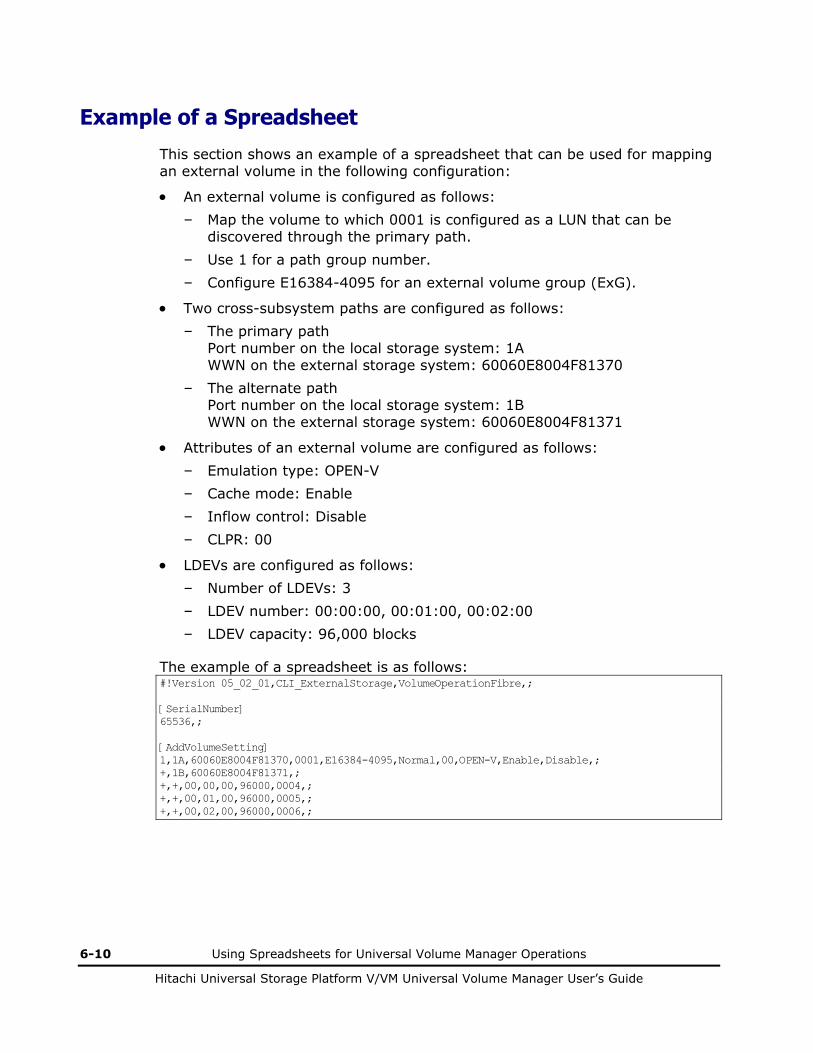
6-10 Using Spreadsheets for Universal Volume Manager Operations
Hitachi Universal Storage Platform V/VM Universal Volume Manager User’s Guide
Example of a Spreadsheet
This section shows an example of a spreadsheet that can be used for mapping an external volume in the following configuration:
• An external volume is configured as follows:
– Map the volume to which 0001 is configured as a LUN that can be discovered through the primary path.
– Use 1 for a path group number.
– Configure E16384-4095 for an external volume group (ExG).
• Two cross-subsystem paths are configured as follows:
– The primary path Port number on the local storage system: 1A WWN on the external storage system: 60060E8004F81370
– The alternate path Port number on the local storage system: 1B WWN on the external storage system: 60060E8004F81371
• Attributes of an external volume are configured as follows:
– Emulation type: OPEN-V
– Cache mode: Enable
– Inflow control: Disable
– CLPR: 00
• LDEVs are configured as follows:
– Number of LDEVs: 3
– LDEV number: 00:00:00, 00:01:00, 00:02:00
– LDEV capacity: 96,000 blocks
The example of a spreadsheet is as follows: #!Version 05_02_01,CLI_ExternalStorage,VolumeOperationFibre,; [SerialNumber] 65536,; [AddVolumeSetting] 1,1A,60060E8004F81370,0001,E16384-4095,Normal,00,OPEN-V,Enable,Disable,; +,1B,60060E8004F81371,; +,+,00,00,00,96000,0004,; +,+,00,01,00,96000,0005,; +,+,00,02,00,96000,0006,;

7
Remote Command Devices 7-1
Hitachi Universal Storage Platform V/VM Universal Volume Manager User’s Guide
Remote Command Devices
This chapter describes remote command devices.
Overview of Remote Command Devices
Guidelines for Remote Command Devices
Mapping a Command Device as a Remote Command Device
Using TrueCopy or Universal Replicator with Remote Command Device

7-2 Remote Command Devices
Hitachi Universal Storage Platform V/VM Universal Volume Manager User’s Guide
Overview of Remote Command Devices
A remote command device is a device in the local storage system to which a command device in the external storage system is mapped.
As you send the CCI commands to the remote command device, you can enter these CCI commands to the command device of the external storage system to operate the CCI in the external storage system.
Figure 7-1 shows an example. The OPEN host that is connected to the local storage system sends the CCI commands of ShadowImage or TrueCopy to the remote command device, and this means that the commands are entered to the command device in the external storage system to operate the ShadowImage pair or the TrueCopy pair in the external storage system.
For detailed information about CCI and the command device, see the Command Control Interface User and Reference Guide.
Open-system Host
CCI
Remote Command Device
Connected by Open Fibre
Mapped as Remote Command Device
TrueCopy Pair
ShadowImage Pair
: Remote command device
: Command device
: Logical device
: CCI commands
Local Storage System External Storage System
Connected byOpen Fibre
Legend
: Lines showing the concept of mapping.
Connected by Open Fibre
Figure 7-1 Outline of Remote Command Device

Remote Command Devices 7-3
Hitachi Universal Storage Platform V/VM Universal Volume Manager User’s Guide
Guidelines for Remote Command Devices
Notices on remote command device are as follows:
• You can map a command device as a remote command device when one of the following storage systems is connected as an external storage system.
– Universal Storage Platform V
– Universal Storage Platform VM
– TagmaStore Universal Storage Platform
– TagmaStore Network Storage Controller
– TagmaStore Adaptable Modular Storage
– TagmaStore Workgroup Modular Storage
– Lightning 9900V series
– Thunder 9500V series
– SANRISE Universal Storage Platform
– SANRISE Network Storage Controller
– SANRISE Adaptable Modular Storage
– SANRISE Workgroup Modular Storage
– SANRISE9900V series
– SANRISE9500V series
– H24000
– H20000
– SANRISE H12000
– SANRISE H10000
– SANRISE H1024/H128
– XP24000
– XP20000
– XP12000
– XP10000
– XP1024/XP128
• You do not need the license for Universal Volume Manager to map a command device as a remote command device.

7-4 Remote Command Devices
Hitachi Universal Storage Platform V/VM Universal Volume Manager User’s Guide
• The remote command devices are displayed in the Device column on the Volume Operation window as follows:
Table 7-1 Displayed Information in Device Column for Remote Command Device
Storage System Displayed Information in Device Column
Universal Storage Platform V
Universal Storage Platform VM
TagmaStore Universal Storage Platform
TagmaStore Network Storage Controller
Lightning 9900V series
SANRISE Universal Storage Platform
SANRISE Network Storage Controller
SANRISE9900V series
H24000
H20000
SANRISE H12000
SANRISE H10000
SANRISE H1024/H128
XP24000
XP20000
XP12000
XP10000
XP1024/XP128
Format: "Emulation Type" + "-CM"
Example: OPEN-V-CM, OPEN-3-CM
TagmaStore Adaptable Modular Storage
TagmaStore Workgroup Modular Storage
Thunder 9500V series
SANRISE Adaptable Modular Storage
SANRISE Workgroup Modular Storage
SANRISE9500V series
DF600F-CM
• If you access the remote command device from an OPEN host, the device information that is reported by the remote command device is about the command device, which is mapped as a remote command device, of the external storage system.
The device information about the command device that is reported to the host by the remote command device includes the followings:
– Serial number
– Vendor
– Device name
Note: The device name that is reported to the host is same as the one displayed in the Device column of the Volume Operation window. For the device name that is reported to the host, see Table 7-1.

Remote Command Devices 7-5
Hitachi Universal Storage Platform V/VM Universal Volume Manager User’s Guide
• Even if the status of the remote command device is normal, an error may occur when the operations or commands are performed on the remote command device.
If an error occurs even though the status of the remote command device is normal, check the status of the command device of the external storage system, not the remote command device.
• There are following restrictions for mapping a command device as a remote command device.
Table 7-2 Restrictions on Remote Command Device
Item Restriction
Emulation type OPEN-V
Number of LDEVs in an external volume 1
Cache mode Disable
Minimum capacity 96,000 Blocks (about 47 MB)
Maximum capacity 4 TB
• The remote command device cannot be identified by the Port Discovery or Volume Discovery of Universal Volume Manager.
• When an external storage system (A) has a remote command device (B) (that is, when a command device in another external storage system (C) is mapped to this external storage system (A)), make sure that the remote command device (B) does not have the smallest LUN on the port in the external storage system (A).
• You cannot execute I/Os to the remote command device.
• You cannot set the command device disable on the remote command device.
• You cannot set the command device security on the remote command device.
• Do not set the command device security on the external storage system side for the command device that is mapped as a remote command device.
• You cannot create a LUSE volume using a remote command device.
• You cannot create CVs using the VLL function in the remote command device.
• Cache Residency Manager is not available on the remote command device.

7-6 Remote Command Devices
Hitachi Universal Storage Platform V/VM Universal Volume Manager User’s Guide
Mapping a Command Device as a Remote Command Device
The command devices that can be mapped as remote command devices are displayed in the Device column of the Volume Operation window as shown in Table 7-1.
To map a command device, select a command device that can be mapped and follow the procedure in Mapping an External Volume Automatically.
Using TrueCopy or Universal Replicator with Remote Command Device
When you want to use TrueCopy or Universal Replicator with a remote command device, you need two different kinds of ports, which are an initiator port for TrueCopy or Universal Replicator and an external port for the remote command device. However, if you set the Initiator/External MIX mode, you will be able to use a port as both initiator port for TrueCopy or Universal Replicator and external port only for the remote command device.
Before you set the Initiator/External MIX mode, you need to prepare initiator ports and external ports in one port block of the Standard mode. You can set the Initiator/External MIX mode on the port block that consists of the initiator ports and external ports.
Figure 7-2 shows difference between the Standard mode and Initiator/External MIX mode. When the Standard mode is set to the ports, you have to connect the cables for both initiator port and external port. However, if you set the Initiator/External MIX mode, you just need to connect one cable, and you can use TrueCopy or Universal Replicator and remote command device.
For detailed information on the port block and setting the Initiator/External MIX mode, see the LUN Manager User’s Guide.

Remote Command Devices 7-7
Hitachi Universal Storage Platform V/VM Universal Volume Manager User’s Guide
CL1-A Initiator
Standard
Port Block (All ports are in the Standard mode.)
: Cable : Ports of Standard mode : Ports of Initiator/External MIX mode
CL3-A ExternalStandard
CL5-A Initiator
Standard
CL7-A ExternalStandard
CL1-A
Initiator MIX
Port Block (All ports are in the Initiator/External MIX mode.)
CL3-A [1-A 2nd]External
MIX
CL5-A
Initiator MIX
CL7-A [5-A 2nd]External
MIX
Legend
Figure 7-2 Difference between Standard Mode and Initiator/External MIX Mode
Figure 7-3 shows an example of using TrueCopy or Universal Replicator with remote command device. The System 1 functions as MCU of TrueCopy or Universal Replicator, and at the same time it functions as the local storage system of the remote command device. the System 2 functions as RCU of TrueCopy or Universal Replicator, and at the same time it functions as the external storage system of the remote command device. In this case, the setting of TrueCopy pair or Universal Replicator pair and setting of the remote command device are both made using the port of the Initiator/External MIX mode. As this example shows, you only need to connect one cable to one of the ports that are set to the Initiator/External MIX mode, this means that you do not need to connect cables to each port of different port attributes.

7-8 Remote Command Devices
Hitachi Universal Storage Platform V/VM Universal Volume Manager User’s Guide
Open-system Host 1
CCI
System 1
Legend
: Lines showing the concept of mapping
TrueCopy or Universal Replicator Pair : Remote command device
: Command device
: Logical device
System 2
Target Port
P-VOL S-VOL
Open-system Host 2
CCI
Target Port
- MCU - Local Storage System
- RCU - External Storage System
LAN
Port of Initiator/External
MIX Mode
RCU TargetPort
Figure 7-3 Example of Using TrueCopy or Universal Replicator with Remote Command Device
Procedure to Use Initiator/External MIX Mode
This section describes the procedure to use the Initiator/External MIX mode and the procedure to stop using the Initiator/External MIX mode.
To use the Initiator/External MIX mode:
1. Prepare the initiator ports of the Standard mode and external ports of the Standard mode in one port block.
For procedure to set the port attribute to initiator, see the TrueCopy User's Guide or the Universal Replicator User's Guide.
2. Set the Initiator/External MIX mode to the port block consisting of the initiator ports of the Standard mode and external ports of the Standard mode.

Remote Command Devices 7-9
Hitachi Universal Storage Platform V/VM Universal Volume Manager User’s Guide
For procedure to set the Initiator/External MIX mode, see the LUN Manager User’s Guide.
3. Connect the cable to the port, and connect a storage system to be used as an MCU and local storage system and a storage system to be used as an RCU and external storage system.
4. Map the command device as the remote command device.
Note: Only the command device can be recognized when the discovery operation is performed using the external port of the Initiator/External MIX mode.
5. Start the operation of TrueCopy or Universal Replicator and operation of the remote command device using the port of the Initiator/External MIX mode.
To stop using the Initiator/External MIX mode:
1. Stop the copy processing and operation of TrueCopy and Universal Replicator.
2. Stop accessing the remote command device.
3. Delete the mapping of the remote command device.
4. Change the setting of the port block from the Initiator/External MIX mode to the Standard mode.
For procedure to change the setting of the port block, see the LUN Manager User’s Guide.
Restrictions on Initiator/External MIX Mode
The restrictions on the Initiator/External MIX mode are as follows:
• The restrictions on the High Speed mode are also restrictions on the Initiator/External MIX mode. For the restrictions on the High Speed mode, see the LUN Manager User’s Guide.
• The point-to-point connection is not available.
• You cannot set the Initiator/External MIX mode on the external ports of the Standard mode that have already been used to map the external volumes. You cannot set the Standard mode on the port of the Initiator/External MIX mode that has already been used to map the remote command device. You need to delete the mapping of the external volume and then change the setting of the port mode.
• Using a port of the Initiator/External MIX mode, the command device of the external storage system can only be recognized by the discovery operation and mapped. Other volumes can be neither recognized by the discovery operation nor mapped using the port of the Initiator/External MIX mode.

7-10 Remote Command Devices
Hitachi Universal Storage Platform V/VM Universal Volume Manager User’s Guide

8
Troubleshooting 8-1
Hitachi Universal Storage Platform V/VM Universal Volume Manager User’s Guide
Troubleshooting
This chapter provides troubleshooting information for Universal Volume Manager.
Troubleshooting
Calling the Hitachi Data Systems Support Center

8-2 Troubleshooting
Hitachi Universal Storage Platform V/VM Universal Volume Manager User’s Guide
Troubleshooting
If you have a problem with the Storage Navigator computer or Storage Navigator software, see the Storage Navigator User’s Guide for troubleshooting information.
Table 8-1 provides general troubleshooting instructions for Universal Volume Manager operations. If you need to call the Hitachi Data Systems Support Center, see Calling the Hitachi Data Systems Support Center for instructions.
Table 8-1 General Troubleshooting for Universal Volume Manager
Error Corrective Action
The Storage Navigator computer cannot access the external volume.
Remove the error and retry the operation.
The reason for the error could be as follows:
The switch is off.
An error occurred in the switch.
The cables are not properly connected.
Configuration in the external storage system is altered, and the specified external volume has already been deleted.
An error on the external volume in the external storage system has occurred.
The path has been changed in the external storage system.
The port attribute of the local storage system has been changed.
The topology information has not been properly set.
The external volume cannot be mapped as an internal volume of the local storage system.
Remove the error and retry the operation. The reason for the error could be as follows:
The number of mapped volumes exceeds the maximum number (63,232) available for the local storage system.
There are not enough LDKC:CU:LDEV numbers available for external volume mapping.
The path to the external volume is blocked.
1. The factors listed in the first row of Table 8-1 (Error: The Storage Navigator computer cannot access to the external volume) could also be the factor of this error. Check the factors of the first row, remove the error and retry the operation. When the error still remains, try step 2.
2. Try the following procedures. If the following procedures do not work and the path is not restored, call the Hitachi Data Systems Support Center.
Confirm that the cable between the local storage system and the external storage system is connected properly.
When the cable between the local storage system and the external storage system is connected properly, disconnect it once and connect it appropriately again. After 30 seconds, check the path status from Storage Navigator.
The path status that requires the reaction is displayed in the Mapping Path Information dialog box.
The following show the description on the path statuses that are displayed in the Status column in the Mapping Path Information dialog box and the reactions for them. The notes on connecting each storage system as an external storage system are in Connecting External Storage Systems. See Connecting External Storage Systems for settings of connection and examples of recovery procedure, and then take corrective actions.

Troubleshooting 8-3
Hitachi Universal Storage Platform V/VM Universal Volume Manager User’s Guide
Error Corrective Action
The displayed statuses are as follows:
Unknown Status: The status of the path is unknown.
Reaction: The status of the path cannot be identified. Please call the Hitachi Data Systems Support Center.
Blockade Status: The external port is blocked.
Reaction: The external port is blocked because of the microprogram replacement or package replacement or some other factor. Check the status of the local storage system. If you cannot restore the path, call the Hitachi Data Systems Support Center.
External device setting changed
Status: The setting of the external storage system has been changed. For example, the path definition was deleted, or the external storage system itself was replaced by another device.
Reaction: The port of the external storage system is recognized. Refer to the documents for your external storage system, and check if the operation that changes the setting information about the mapped device has not been performed.
LDEV size reduced
Status: The setting of the volume capacity of the external storage system has been changed (the volume capacity was reduced).
Reaction: Check the volume capacity of the volume of the external storage system. Execute the Delete Volume operation, and then retry the Add Volume operation.
Not ready Status: The reply of the external storage system was NOTREADY. The drive of the external storage system is spinning up, or the device of the external storage system is being formatted.
Reaction: The path cannot be used to access the external storage system. Check the status of the external storage system. If you cannot restore the path, call the Hitachi Data Systems Support Center.
Illegal request
Status: The reply of the external storage system was ILLEGALREQUEST. The command cannot be executed to the device of the external storage system. The data protection may be set on the device of the external storage system.
Reaction: The port of the external storage system is recognized. Check the setting of the external storage system. If you cannot restore the path, call the Hitachi Data Systems Support Center.
Command aborted
Status: The reply of the external storage system was ABORTEDCOMMAND. An error may have occurred on the external storage system side.
Reaction: The port of the external storage system is recognized. Check the setting of the external storage system and the condition of the connection (e.g., cables, switches) to the external storage system. If you cannot restore the path, call the Hitachi Data Systems Support Center.
Busy Status: The external storage system is in the BUSY status.
Reaction: The port of the external storage system is recognized. Check the setting of the external storage system and the load on the external storage system (e.g., check if the configuration gives too much load on the external storage system or not). If you cannot restore the path, call the Hitachi Data Systems Support Center.
LDEV reserved
Status: The external storage system is in the Reserve status. You are not allowed to access the device of the external storage system from the local storage system
Reaction: Remove the Reserve status on the device of the external storage system.

8-4 Troubleshooting
Hitachi Universal Storage Platform V/VM Universal Volume Manager User’s Guide
Error Corrective Action
Response error
Status: The external storage system is in the blocked status caused by the abnormal reply (Response). You may not be able to access the device of the external storage system. Or data protection may be set on the device of the external storage system.
Reaction: The port of the external storage system is recognized. Check the setting and status of the external storage system. If you cannot restore the path, call the Hitachi Data Systems Support Center.
Initiator port
Status: The port attribute of the external storage system has been changed to the initiator port.
Reaction: Set the port attribute of the external storage system to the target port. If you cannot restore the path, call the Hitachi Data Systems Support Center.
Unknown port
Status: The port attribute of the external storage system is unknown.
Reaction: The port of the external storage system is recognized. Check the condition of the connection (e.g., cables, switches) to the external storage system. If you cannot restore the path, call the Hitachi Data Systems Support Center.
Cannot detect port
Status: The path has been removed or the port of the external storage system cannot be found. There is a problem with connection to the external storage system. The following are possible causes:
- The fibre cable is not physically connected in the proper way.
- The setting of the topology does not match between the external port and the target port.
- Because the security is set on the port, the device of the external storage system cannot be recognized from the local storage system.
- If the external storage system is connected through switches, the settings for the switches may not be appropriate.
Reaction: Check the condition of the connection to the external storage system. If you cannot restore the path, call the Hitachi Data Systems Support Center.
Internal error
Status: The program error occurred. Or there is a logical contradiction.
Reaction: Call the Hitachi Data Systems Support Center.
Timeout Status: The processing was retried because the abnormal reply (Response) was returned, however, the processing has been stopped by timeout.
Reaction: The port of the external storage system is recognized. Check the condition of the connection (e.g., cables, switches) to the external storage system. If you cannot restore the path, call the Hitachi Data Systems Support Center.
Target error
Status: An error such as the blockade of the controller has been found in the port of the external storage system
Reaction: Check the status of the ports of the external storage system. If you cannot restore the path, call the Hitachi Data Systems Support Center.

Troubleshooting 8-5
Hitachi Universal Storage Platform V/VM Universal Volume Manager User’s Guide
Error Corrective Action
Unavailable
Status: The reply of the external storage system was Unavailable. The external storage system demands to change the connected port. Once the status becomes Unavailable, the primary path is changed to the alternate path that is in the Standby status. When the primary path has been changed, the status of the path becomes Normal.
Reaction: If the path is not changed over properly, check the status of the external storage system. If you cannot restore the path, call the Hitachi Data Systems Support Center.
Backoff Status: The reply of the external storage system was Backoff. The status of the path is waiting for recovery because a temporary error has occurred in the volume of the external storage system. Even if the status of the primary path becomes this status, the primary path is not changed to the alternate path immediately. After the error recovery, the status becomes Normal.
Reaction: If the status cannot be recovered from the error, the path status is changed to another status. React to the new path status after the status is changed. If you cannot restore the path, call the Hitachi Data Systems Support Center.
The volume in the external storage system cannot be found even after the Port Discovery or the Volume Discovery was performed.
Remove the error and retry the operation. The reason for the error could be as follows:
Storage Navigator is not in the Modify mode.
Port of the local storage system and the port of the external storage system are not connected.
Port security is set on the external storage system.
The device in the external storage system is not in the Normal status.
External storage system is not connected to the port set to External of the local storage system.
The capacity is not enough (capacity is less than about 38 MB (77,760 blocks) .
The cable for the switch is not connected appropriately.
The zoning for the switch is not set appropriately.
If none of the above corresponds to the actual factor, disconnect the cable between the local storage system and the external storage system once and connect it appropriately again. After 30 seconds, retry the operation.
The external volume is blocked.
Remove the error and retry the operation.
The reason for the error could be as follows:
All the set paths are blocked (paths are not connected).
The attribute of external volume is not set to Read/ Write attribute.
The external volume is blocked by error.
The Check Paths & Restore Volume command is executed and you have waited more than 10 minutes, but the status of the device does not change from Checking.
Click Refresh ( ) command on the Storage Navigator main window while the
Status: Enable button is displayed. If the device status remains as Checking even though you have updated the information, execute the Check Paths & Restore Volume command again.
If the same problem persists despite retrying, call the Hitachi Data Systems Support Center.

8-6 Troubleshooting
Hitachi Universal Storage Platform V/VM Universal Volume Manager User’s Guide
Error Corrective Action
The Disconnect Subsystem command or the Disconnect Volume command is executed, but the progress status information is not updated.
Click Refresh ( ) command on the Storage Navigator main window while the
Status: Enable button is displayed. If the progress information about the Cache Destage status is not updated even though you have updated the information, call the Hitachi Data Systems Support Center.
Note: The time required for the writing processing of data from the cache to the external volume (destaging processing) depends on the volume capacity (more time is required for the larger volume than the smaller one). The processing speed is about 20 MB/s. However, the processing speed depends on the performance and the status of the external storage system.
The message of “INTERVENTION REQUIRED” is issued to the mainframe host as the device status.
The device status is currently changing. Please wait for a while, and then check the device status again. When the transition of the device status has completed normally, the device can be used immediately. If the device is blocked as a result of the device status transition, see the error description "The external volume is blocked." in Table 8-1 for the corrective action.
The message of “DEVICE ERROR” is issued to the mainframe host as the device status.
See the error description "The external volume is blocked." in Table 8-1 for the corrective action.
Calling the Hitachi Data Systems Support Center
If you need to call the Hitachi Data Systems Support Center, make sure to provide as much information about the problem as possible, including:
• The circumstances surrounding the error or failure.
• The exact content of any error messages displayed on the host system(s).
• The exact content of any error messages displayed by Storage Navigator.
• The Storage Navigator configuration information (use the FD Dump Tool).
• The service information messages (SIMs), including reference codes and severity levels, displayed by Storage Navigator.
The Hitachi Data Systems customer support staff is available 24 hours/day, seven days a week. If you need technical support, please call:
• United States: (800) 446-0744
• Outside the United States: (858) 547-4526

A
Connecting External Storage Systems A-1
Hitachi Universal Storage Platform V/VM Universal Volume Manager User’s Guide
Connecting External Storage Systems
TagmaStore AMS/WMS Storage System
System Parameters for Connecting TagmaStore AMS/WMS Storage System
The table below explains whether to specify system parameters when making settings on ports on the TagmaStore AMS and WMS storage systems.
Note: When you connect a TagmaStore AMS or WMS storage system, use LUN Manager to set the data transfer speed of the external port which you use to a fixed value other than the Auto. Also, set the data transfer speed of the target port of the AMS/WMS storage system to the fixed value according to the data transfer speed of the external port.
Table A-1 System Parameter Settings (AMS/WMS)
Window Names Parameters Parameter Settings
Start Attribute
Single Mode Specify this parameter when AMS/WMS storage system is in the one controller configuration.
Dual Active Mode Specify this parameter when AMS/WMS storage system is in the two controller configuration.
Delay Planned Shutdown You can either specify this parameter or omit specifying this parameter.
Drive blocking mode You can either specify this parameter or omit specifying this parameter.
Vendor ID Keep this parameter as HITACHI (default), and do not change.
Product ID Keep this parameter as DF600F (default), and do not change.
Boot Options
ROM Microprogram Version You can either specify this parameter or omit specifying this parameter.

A-2 Connecting External Storage Systems
Hitachi Universal Storage Platform V/VM Universal Volume Manager User’s Guide
Window Names Parameters Parameter Settings
RAM Microprogram Version You can either specify this parameter or omit specifying this parameter.
Option You can either specify this parameter or omit specifying this parameter.
Operation if the processor failure occurs
Specify this parameter to Reset of occurred.
WEB Title You can either specify this parameter or omit specifying this parameter.
System Parameter
Write and verify mode Set this parameter to ON.
Port Options Port Option You can either specify this parameter or omit specifying this parameter.
Host Connection Mode 1 Set this parameter to Standard Mode. Host Connection Mode
Host Connection Mode 2 Do not specify any parameters.
Note: Do not specify HISUP OFF mode, either.
Note: You can either specify or omit any other parameters.
Relationship between Serial Number and AMS/WMS Model
When the external storage system is TagmaStore AMS or WMS, you can identify the storage system model from the serial number displayed in the Serial Number column in the Volume Operation window.
The following table describes the relationship between serial number displayed in the Serial Number column and the storage system model.
Table A-2 Relationship between Serial Number and AMS/WMS Model
Storage System Displayed Serial Number Model
77XXXXXX AMS 1000
75XXXXXX AMS 500
AMS
73XXXXXX AMS 200
WMS 71XXXXXX WMS 100
Note: In serial numbers, "X" is an arbitrary number or character.

Connecting External Storage Systems A-3
Hitachi Universal Storage Platform V/VM Universal Volume Manager User’s Guide
Relationship between WWN of Port and Controller (AMS/WMS)
When the external storage system is TagmaStore AMS or WMS, you can identify the controller (controller 0 or controller 1) from the WWN of the port.
The following table describes the relationship between WWN of port and controller.
Table A-3 Relationship between WWN of Port and Controller (AMS/WMS)
Model Controller WWN of Port
Controller 0 XXXXXXXXXXXXXXX0 AMS 200
WMS 100
Controller 1 XXXXXXXXXXXXXXX1
Controller 0 XXXXXXXXXXXXXXX0
XXXXXXXXXXXXXXX1
AMS 500
Controller 1 XXXXXXXXXXXXXXX2
XXXXXXXXXXXXXXX3
Controller 0 XXXXXXXXXXXXXXX0
XXXXXXXXXXXXXXX1
XXXXXXXXXXXXXXX2
XXXXXXXXXXXXXXX3
AMS 1000
Controller 1 XXXXXXXXXXXXXXX4
XXXXXXXXXXXXXXX5
XXXXXXXXXXXXXXX6
XXXXXXXXXXXXXXX7
Note: In WWNs, "X" is an arbitrary number or character. The ports in the same apparatus has the identical value.

A-4 Connecting External Storage Systems
Hitachi Universal Storage Platform V/VM Universal Volume Manager User’s Guide
Path Status and Examples of Recovery Procedure (AMS/WMS)
This section describes errors that require recovery operation on the external storage system side when the path status is not normal. When the path status is not normal, see the following table to recover the path status. If you cannot restore the path, call the Hitachi Data Systems Support Center (see Calling the Hitachi Data Systems Support Center).
Table A-4 Path Status and Examples of Recovery Procedure (AMS/WMS)
Path Status Examples of Recovery Procedure
External device setting changed
Settings of the LU paths may have been changed by LUN Manager. Check the settings of the LU paths. If the settings of the LU paths have been changed, change the settings back to the ones when the volume is mapped. Or use Universal Volume Manager to perform the Delete LU operation and perform the Add LU operation again.
The access attribute of the volume may have been changed by Data Retention Utility. Check the access attribute of the volume. If the volume is protected by the access attribute, release the protection.
Illegal request or Response error
The volume may have been set as a pair volume for data copy. Check if the volume is set as a pair volume of ShadowImage, TrueCopy or some other copy program. If the volume is set as a pair volume, the volume may be protected because of the pair status. When the volume is protected, change the pair status or delete the pair.
The access attribute of the volume may have been changed by Data Retention Utility. Check the access attribute of the volume. If the volume is protected by the access attribute, release the protection.
Cannot detect port
There is a problem with connection to the external storage system. The possible causes are:
The fibre cable is not physically connected in the proper way.
The setting of the topology does not match between the external port and the target port.
If the external storage system is connected through switches, the settings for the switches may not be appropriate.
Make sure that the fibre cable is connected properly, and then set the fibre-channel port properly using LUN Manager.
If host group security is enabled, disable host group security using LUN Manager.

Connecting External Storage Systems A-5
Hitachi Universal Storage Platform V/VM Universal Volume Manager User’s Guide
Thunder 9500V Storage System
System Parameters for Connecting Thunder 9500V
The table below explains whether to specify system parameters when making settings on ports on the Thunder 9500V storage system.
Table A-5 System Parameter Settings (9500V)
Window Names Parameters Parameter Settings
System Startup Settings
Start Attribute
Single Mode Specify this parameter when Thunder 9500V storage system is in the one controller configuration.
Dual Active Mode Specify this parameter when Thunder 9500V storage system is in the two controller configuration.
Note: Be sure to specify that Data Share Mode will be used.
Hot Stand-By Mode Do not specify this parameter.
Common 1 Delay Planned Shutdown You can either specify this parameter or omit specifying this parameter.
OPTION 1 SCSI Fibre Channel Common Options
You can either specify this parameter or omit specifying this parameter.
OPTION 2 SCSI Fibre Channel Common Options
You can either specify this parameter or omit specifying this parameter.
Data Striping Operation if the processor failure occurs
Specify this parameter to Reset of occurred.
Command Queuing Mode Specify this parameter ON.
Vendor ID Keep this parameter as HITACHI (default), and do not change.
Product ID Keep this parameter as DF600F (default), and do not change.
ROM Microprogram Version You can either specify this parameter or omit specifying this parameter.
RAM Microprogram Version You can either specify this parameter or omit specifying this parameter.
Inquiry Setting
WEB Title You can either specify this parameter or omit specifying this parameter.
Reset/LIP Mode
Reset/LIP Mode (Signal) You can either specify this parameter or omit specifying this parameter.
Port Type
Reset/LIP Mode (Process) You can either specify this parameter or omit specifying this parameter.

A-6 Connecting External Storage Systems
Hitachi Universal Storage Platform V/VM Universal Volume Manager User’s Guide
Window Names Parameters Parameter Settings
LIP Reset Mode You can either specify this parameter or omit specifying this parameter.
RS232C Error Information Outflow Mode
You can either specify this parameter or omit specifying this parameter.
Controller Option
Write and verify mode Set this parameter to ON.
Host Connection Mode
Host Connection Mode 1 Set this parameter to Standard Mode.
Host Connection Mode 2 Specify HISUP Mode.
Note: Do not specify any other parameters.
Note: When you use the Thunder 9500V storage system as an external storage system, the following versions are recommended. If you use a 9500V storage system whose version is earlier than the following versions, the information about the SATA drive may not be displayed correctly. • For Thunder 9530V, Thunder 9520V, Thunder 9570V: version 0658 or
later. • For Thunder 9580V, Thunder 9585V: version 1658 or later.
Relationship between Serial Number and 9500V Model
When the external storage system is Thunder 9500V storage system, you can identify the storage system model from the serial number displayed in the Serial Number column in the Volume Operation window.
The following table describes the relationship between the serial number displayed in the Serial Number column and the storage system model.
Table A-6 Relationship between Serial Number and 9500V Model
Displayed Serial Number Model
D600XXXX 9570V, 9520V
D60JXXXX 9530V
D60HXXXX 9580V, 9585V
Note: In serial numbers, "X" is an arbitrary number or character.
Relationship between WWN of Port and Controller(9500V)
When the external storage system is Thunder 9500V storage system, you can identify the controller (controller 0 or controller 1) from the WWN of the port.

Connecting External Storage Systems A-7
Hitachi Universal Storage Platform V/VM Universal Volume Manager User’s Guide
The following table describes the relationship between WWN of port and controller.
Table A-7 Relationship between WWN of Port and Controller (9500V)
Model Controller WWN of Port
Controller 0 XXXXXXXXXXXXXXX0
XXXXXXXXXXXXXXX1
9570V
9530V
9520V Controller 1 XXXXXXXXXXXXXXX2
XXXXXXXXXXXXXXX3
Controller 0 XXXXXXXXXXXXXXX0
XXXXXXXXXXXXXXX1
XXXXXXXXXXXXXXX2
XXXXXXXXXXXXXXX3
9580V
9585V
Controller 1 XXXXXXXXXXXXXXX4
XXXXXXXXXXXXXXX5
XXXXXXXXXXXXXXX6
XXXXXXXXXXXXXXX7
Note: In WWNs, "X" is an arbitrary number or character. The ports in the same apparatus has the identical value.

A-8 Connecting External Storage Systems
Hitachi Universal Storage Platform V/VM Universal Volume Manager User’s Guide
Path Status and Examples of Recovery Procedure (9500V)
This section describes errors that require recovery operation on the external storage system side when the path status is not normal. When the path status is not normal, see the following table to recover the path status. If you cannot restore the path, call the Hitachi Data Systems Support Center (see Calling the Hitachi Data Systems Support Center).
Table A-8 Path Status and Examples of Recovery Procedure (9500V)
Path Status Examples of Recovery Procedure
External device setting changed
Settings of the LU paths may have been changed by LUN Management. Check the settings of the LU paths. If the settings of the LU paths have been changed, change the settings back to the ones when the volume is mapped. Or use Universal Volume Manager to perform the Delete LU operation and perform the Add LU operation again.
The access attribute of the volume may have been changed by Open LDEV Guard. Check the access attribute of the volume. If the volume is protected by the access attribute, release the protection.
Illegal request or
Response error
The volume may have been set as a pair volume for data copy. Check if the volume is set as a pair volume of ShadowImage, TrueCopy or some other copy program. If the volume is set as a pair volume, the volume may be protected because of the pair status. When the volume is protected, change the pair status or delete the pair.
The access attribute of the volume may have been changed by Open LDEV Guard. Check the access attribute of the volume. If the volume is protected by the access attribute, release the protection.
Cannot detect port There is a problem with connection to the external storage system. The possible causes are:
The fibre cable is not physically connected in the proper way.
The setting of the topology does not match between the external port and the target port.
If the external storage system is connected through switches, the settings for the switches may not be appropriate.
Make sure that the fibre cable is connected properly, and then set the fibre channel port properly using LUN Management.
The host group security may have been enabled by LUN Management. Check if the host group security is enabled or not. If the host group security is enabled, disable the host group security.

Connecting External Storage Systems A-9
Hitachi Universal Storage Platform V/VM Universal Volume Manager User’s Guide
USP V/VM Storage System
When you connect a USP V/VM storage system as the external storage system, you need to set the port to the host group for the Windows hosts (host mode 0C: Windows, host mode 2C: Windows Extension).
Also, the port attribute must be the target port or the RCU target port.
Path Status and Examples of Recovery Procedure (USP V/VM)
This section describes errors that require recovery operation on the external storage system side when the path status is not normal. When the path status is not normal, see the following table to recover the path status. If you cannot restore the path, call the Hitachi Data Systems Support Center (see Calling the Hitachi Data Systems Support Center).
Table A-9 Path Status and Examples of Recovery Procedure (USP V/VM)
Path Status Examples of Recovery Procedure
External device setting changed
Settings of the LU paths may have been changed by LUN Manager. Check the settings of the LU paths. If the settings of the LU paths have been changed, change the settings back to the ones when the volume is mapped. Or use Universal Volume Manager to perform the Delete Volume operation and perform the Add Volume operation again.
The access attribute of the volume may have been changed by Data Retention Utility. Check the access attribute of the volume. If the volume is protected by the access attribute, release the protection.
Illegal request or
Response error
The volume may have been set as a pair volume for data copy. Check if the volume is set as a pair volume of ShadowImage, TrueCopy, Universal Replicator or some other copy program. If the volume is set as a pair volume, the volume may be protected because of the pair status. When the volume is protected, change the pair status or delete the pair.
The access attribute of the volume may have been changed by Data Retention Utility. Check the access attribute of the volume. If the volume is protected by the access attribute, release the protection.
Cannot detect port
There is a problem with connection to the external storage system. The possible causes are:
The fibre cable is not physically connected in the proper way.
The setting of the topology does not match between the external port and the target port.
If the external storage system is connected through switches, the settings for the switches may not be appropriate.
Make sure that the fibre cable is connected properly, and then set the fibre channel port properly using LUN Manager.
The LUN security may have been enabled by LUN Manager. Check if the LUN security is enabled or not. If the LUN security is enabled, disable the LUN security.

A-10 Connecting External Storage Systems
Hitachi Universal Storage Platform V/VM Universal Volume Manager User’s Guide
TagmaStore USP/NSC Storage System
When you connect a TagmaStore USP or NSC storage system as the external storage system, you need to set the port to the host group for the Windows hosts (host mode 0C: Windows, host mode 2C: Windows Extension).
Also, the port attribute must be the target port or the RCU target port.
Setting the Host Mode Option When a Volume of More Than 2 TB Is Used (USP/NSC)
If a volume, which has the capacity of more than 2TB, is mapped as an external volume, host mode option No. 24 must be enabled. If No. 24 is disabled, a volume, which has the capacity of more than 2TB, cannot be mapped as an external volume. For how to set the host mode option, see the LUN Manager User’s Guide of TagmaStore USP or NSC storage system.
Path Status and Examples of Recovery Procedure (USP/NSC)
This section describes errors that require recovery operation on the external storage system side when the path status is not normal. When the path status is not normal, see the following table to recover the path status. If you cannot restore the path, call the Hitachi Data Systems Support Center (see Calling the Hitachi Data Systems Support Center).
Table A-10 Path Status and Examples of Recovery Procedure (USP/NSC)
Path Status Examples of Recovery Procedure
External device setting changed
Settings of the LU paths may have been changed by LUN Manager. Check the settings of the LU paths. If the settings of the LU paths have been changed, change the settings back to the ones when the volume is mapped. Or use Universal Volume Manager to perform the Delete LU operation and perform the Add LU operation again.
The access attribute of the volume may have been changed by Data Retention Utility. Check the access attribute of the volume. If the volume is protected by the access attribute, release the protection.
Illegal request or
Response error
The volume may have been set as a pair volume for data copy. Check if the volume is set as a pair volume of ShadowImage, TrueCopy, Universal Replicator or some other copy program. If the volume is set as a pair volume, the volume may be protected because of the pair status. When the volume is protected, change the pair status or delete the pair.
The access attribute of the volume may have been changed by Data Retention Utility. Check the access attribute of the volume. If the volume is protected by the access attribute, release the protection.

Connecting External Storage Systems A-11
Hitachi Universal Storage Platform V/VM Universal Volume Manager User’s Guide
Path Status Examples of Recovery Procedure
Cannot detect port
There is a problem with connection to the external storage system. The possible causes are:
The fibre cable is not physically connected in the proper way.
The setting of the topology does not match between the external port and the target port.
If the external storage system is connected through switches, the settings for the switches may not be appropriate.
Make sure that the fibre cable is connected properly, and then set the fibre channel port properly using LUN Manager.
The LUN security may have been enabled by LUN Manager. Check if the LUN security is enabled or not. If the LUN security is enabled, disable the LUN security.
Lightning 9900V Storage System
When you connect a Lightning 9900V storage system as the external storage system, you need to set the port to the host group for the Windows hosts (host mode 0C: Windows, host mode 2C: Windows Extension).
Also, the port attribute must be the target port or the RCU target port.
Path Status and Examples of Recovery Procedure (9900V)
This section describes errors that require recovery operation on the external storage system side when the path status is not normal. When the path status is not normal, see the following table to recover the path status. If you cannot restore the path, call the Hitachi Data Systems Support Center (see Calling the Hitachi Data Systems Support Center).
Table A-11 Path Status and Examples of Recovery Procedure (9900V)
Path Status Examples of Recovery Procedure
External device setting changed
Settings of the LU paths may have been changed by LUN Manager. Check the settings of the LU paths. If the settings of the LU paths have been changed, change the settings back to the ones when the volume is mapped. Or use Universal Volume Manager to perform the Delete LU operation and perform the Add LU operation again.
The access attribute of the volume may have been changed by Open LDEV Guard. Check the access attribute of the volume. If the volume is protected by the access attribute, release the protection.
Illegal request or
Response error
The volume may have been set as a pair volume for data copy. Check if the volume is set as a pair volume of ShadowImage, TrueCopy, or some other copy program. If the volume is set as a pair volume, the volume may be protected because of the pair status. When the volume is protected, change the pair status or delete the pair.
The access attribute of the volume may have been changed by Open LDEV Guard. Check the access attribute of the volume. If the volume is protected by the access attribute, release the protection.

A-12 Connecting External Storage Systems
Hitachi Universal Storage Platform V/VM Universal Volume Manager User’s Guide
Path Status Examples of Recovery Procedure
Cannot detect port
There is a problem with connection to the external storage system. The possible causes are:
The fibre cable is not physically connected in the proper way.
The setting of the topology does not match between the external port and the target port.
If the external storage system is connected through switches, the settings for the switches may not be appropriate.
Make sure that the fibre cable is connected properly, and then set the fibre channel port properly using LUN Manager.
The LUN security may have been set by LUN Manager. Check if the LUN security is set or not. If the LUN security is set, remove the setting of the LUN security.
Lightning 9900 Storage System
When you connect a Lightning 9900 storage system as the external storage system, you need to set the host mode of the port to PC Server (0C).
Also, the port attribute must be the target port or the RCU target port.
Path Status and Examples of Recovery Procedure (9900)
This section describes errors that require recovery operation on the external storage system side when the path status is not normal. When the path status is not normal, see the following table to recover the path status. If you cannot restore the path, call the Hitachi Data Systems Support Center (see Calling the Hitachi Data Systems Support Center).Table A-12 Path Status and Examples of Recovery Procedure (9900)
Path Status Examples of Recovery Procedure
External device setting changed
Settings of the LU paths may have been changed by LUN Manager. Check the settings of the LU paths. If the settings of the LU paths have been changed, change the settings back to the ones when the volume is mapped. Or use Universal Volume Manager to perform the Delete LU operation and perform the Add LU operation again.
Illegal request or
Response error
The volume may have been set as a pair volume for data copy. Check if the volume is set as a pair volume of ShadowImage, TrueCopy, or some other copy program. If the volume is set as a pair volume, the volume may be protected because of the pair status. When the volume is protected, change the pair status or delete the pair.

Connecting External Storage Systems A-13
Hitachi Universal Storage Platform V/VM Universal Volume Manager User’s Guide
Path Status Examples of Recovery Procedure
Cannot detect port There is a problem with connection to the external storage system. The possible causes are:
The fibre cable is not physically connected in the proper way.
The setting of the topology does not match between the external port and the target port.
If the external storage system is connected through switches, the settings for the switches may not be appropriate.
Make sure that the fibre cable is connected properly, and then set the fibre channel port properly using LUN Manager.
The LUN security may have been set by LUN Manager. Check if the LUN security is set or not. If the LUN security is set, remove the setting of the LUN security.
SVS200 Storage System
When you connect a SVS200 storage system as the external storage system, you need to set the port to the host group for the Windows hosts (host mode 0C: Windows, host mode 2C: Windows Extension).
Also, the port attribute must be the target port or the RCU target port.
Note: If you are using the microcode that does not support the SVS200 storage system, the SVS200 storage system is recognized as the XP12000 storage system. If you need the connected external storage system to be recognized as the SVS200 storage system, use the microcode of the version that supports the SVS200 storage system (which is the microcode version 50-07-0X-XX/XX or higher). If you have used an earlier microcode version that does not support the SVS200 storage system to map the volumes of the SVS storage system, delete the setting of mapping and then change the microcode version to the one that supports the SVS200 storage system.

A-14 Connecting External Storage Systems
Hitachi Universal Storage Platform V/VM Universal Volume Manager User’s Guide
Path Status and Examples of Recovery Procedure (SVS200)
This section describes errors that require recovery operation on the external storage system side when the path status is not normal. When the path status is not normal, see the following table to recover the path status. If you cannot restore the path, call the Hitachi Data Systems Support Center (see Calling the Hitachi Data Systems Support Center).
Table A-13 Path Status and Examples of Recovery Procedure (SVS200)
Path Status Examples of Recovery Procedure
External device setting changed
Settings of the LU paths may have been changed by LUN Management. Check the settings of the LU paths. If the settings of the LU paths have been changed, change the settings back to the ones when the volume is mapped. Or use Universal Volume Manager to perform the Delete LU operation and perform the Add LU operation again.
The access attribute of the volume may have been changed by LUN Security XP Extension. Check the access attribute of the volume. If the volume is protected by the access attribute, release the protection.
Illegal request or
Response error
The volume may have been set as a pair volume for data copy. Check if the volume is set as a pair volume of Business Copy XP, Continuous Access XP, Continuous Access XP - Journal, or some other copy program. If the volume is set as a pair volume, the volume may be protected because of the pair status. When the volume is protected, change the pair status or delete the pair.
The access attribute of the volume may have been changed by LUN Security XP Extension. Check the access attribute of the volume. If the volume is protected by the access attribute, release the protection.
Cannot detect port There is a problem with connection to the external storage system. The possible causes are:
The fibre cable is not physically connected in the proper way.
The setting of the topology does not match between the external port and the target port.
If the external storage system is connected through switches, the settings for the switches may not be appropriate.
Make sure that the fibre cable is connected properly, and then set the fibre channel port properly using LUN Management.
The LUN security may have been enabled by LUN Management. Check if the LUN security is enabled or not. If the LUN security is enabled, disable the LUN security.

Connecting External Storage Systems A-15
Hitachi Universal Storage Platform V/VM Universal Volume Manager User’s Guide
EVA Storage System
System Parameter Settings for Connecting EVA Storage System
When you connect an EVA storage system as an external storage system, set the system parameters of the EVA storage system according to the following table. For the system parameters that are not in the following table, refer to the manuals of the EVA storage system and set the parameters appropriately for the connecting configuration.
Table A-14 System Parameter Settings for Connecting EVA Storage System
Parameter Parameter Setting
Add a Host Host OS Windows
Identifying Logical Volume of EVA Storage System (Using Characteristic 2)
When the connected external storage system is an EVA storage system, LUNs are displayed as Characteristic 1 in the Universal Volume Manager windows.
If you search for the logical volumes specifying the WWN indicating the EVA Port A in the configuration such as Figure A-1, the logical volumes named LUN 1 and LUN 2 are found for each of HostGroup-1 and HostGroup-2. In this case, two different logical volumes that have the same name such as LUN 1 and LUN 2 are found as the logical volumes that can be connected from EVA Port A, but you cannot tell which LUN 1 and LUN 2 belong to HostGroup-1 or HostGroup-2 only by Characteristic 1.
In the configuration such as Figure A-1, you can identify the logical volumes referring to Characteristic 2 in the Universal Volume Manager windows. The first 32 characters of Characteristic 2 indicate the World Wide LUN Name that can be found on the EVA storage system side. You can identify the logical volume of the EVA storage system by this World Wide LUN Name.

A-16 Connecting External Storage Systems
Hitachi Universal Storage Platform V/VM Universal Volume Manager User’s Guide
External Port 1
External Port 2
Switch
EVA
LUN 1
LUN 1
LUN 2
LUN 2
HostGroup-1
HostGroup-2
World Wide LUN Name 600508b4 001028cb 00005000 011d0000
EVA Port A
EVA Port B
World Wide LUN Name 600508b4 001028cb 00005000 01200000
World Wide LUN Name 600508b4 001028cb 00005000 01230000
World Wide LUN Name 600508b4 001028cb 00005000 012c0000
Local Storage System
Figure A-1 Configuration Example for which Logical Volumes Cannot be Identified only by Characteristic

Connecting External Storage Systems A-17
Hitachi Universal Storage Platform V/VM Universal Volume Manager User’s Guide
Note on Behavior of Alternate Path when EVA Storage System is Connected
When an EVA storage system is connected, the behavior of the alternate path differs depending on the microprogram version of the EVA storage system.
If the storage system type is EVA3000/5000, the behavior of the alternate path differs between the EVA storage systems of the microprogram version 4.000 or later and the EVA storage systems of the earlier microprogram versions.
If you want to replace the microprogram of the EVA storage system, check whether the behavior of the alternate path changes as a result of changing the microprogram version. If the behavior of the alternate path changes, perform the Delete Volume operation of Universal Volume Manager to release the setting of mapping the EVA storage system volume before you actually replace the microprogram.
Refer to the EVA storage system documentation for how the behavior of the alternate path changes.
System Parameter Settings for Connecting Sun StorEdge 6120/6320
When you connect a Sun StorEdge 6120/6320 as an external storage system, set the system parameters of the Sun StorEdge 6120/6320 according to the following table. For the system parameters that are not in the following table, refer to the documentation of the Sun StorEdge 6120/6320 and set the parameters appropriately for the connecting configuration.
Table A-15 System Parameter Settings for Connecting Sun StorEdge 6120/6320
Parameter Parameter Setting
port host SUN

A-18 Connecting External Storage Systems
Hitachi Universal Storage Platform V/VM Universal Volume Manager User’s Guide
System Parameter Settings for Connecting Sun StorageTek FlexLine 380
When you connect a Sun StorageTek FlexLine 380 as an external storage system, set the system parameters of the Sun StorageTek FlexLine 380 according to the following table. For the system parameters that are not in the following table, refer to the documentation of the Sun StorageTek FlexLine 380 and set the parameters appropriately for the connecting configuration.
Table A-16 System Parameter Settings for Connecting Sun StorageTek FlexLine 380
Parameter Parameter Setting
host type Windows Non-clustered (DMP Support)
System Parameter Settings for Connecting Sun StorageTek 2540
When you connect a Sun StorageTek 2540 as an external storage system, set the system parameters of the Sun StorageTek 2540 according to the following table. For the system parameters that are not in the following table, refer to the documentation of the Sun StorageTek 2540 and set the parameters appropriately for the connecting configuration.
Table A-17 System Parameter Settings for Connecting Sun StorageTek 2540
Parameter Parameter Setting
host type Windows 2K non Clustered DMP
Cross-Subsystem Paths for Connecting Sun StorageTek V2X2
When you connect a Sun StorageTek V2X2 as an external storage system, make sure that only one cross-subsystem path is configured when you map external volumes. Do not add any alternate paths after you finish mapping external volumes.

Connecting External Storage Systems A-19
Hitachi Universal Storage Platform V/VM Universal Volume Manager User’s Guide
System Parameter Settings for Connecting EMC CLARiiON CX600
When you connect an EMC CLARiiON CX600 as an external storage system, set the system parameters of the EMC CLARiiON CX600 according to the following table. For the system parameters that are not in the following table, refer to the documentation of the EMC CLARiiON CX600 and set the parameters appropriately for the connecting configuration.
Table A-18 System Parameter Settings for Connecting EMC CLARiiON CX600
Parameter Parameter Setting
Initiator Type CLARiiON Open
Failover Mode 2
System Parameter Settings for Connecting IBM DS4000 Series
When you connect an IBM DS4000 series as an external storage system, set the system parameters of the IBM DS4000 series according to the following table. For the system parameters that are not in the following table, refer to the documentation of the IBM DS4000 series and set the parameters appropriately for the connecting configuration.
Table A-19 System Parameter Settings for Connecting IBM DS4000 Series
Parameter Parameter Setting
host type When alternate paths are connected to different clusters on the DS4000 series side: Linux
Non-Hitachi Storage Systems
Generally, when you connect a non-Hitachi storage system as the external storage system, the non-Hitachi storage system port must be configured as a target attached to a Windows host. The third-party vendor should be contacted as necessary for the technical details to accomplish this.

A-20 Connecting External Storage Systems
Hitachi Universal Storage Platform V/VM Universal Volume Manager User’s Guide

B
Required Volume Capacity for each Emulation Type B-1
Hitachi Universal Storage Platform V/VM Universal Volume Manager User’s Guide
Required Volume Capacity for Each Emulation Type
When you map an external volume as an internal volume, you need to specify the emulation type for the mapped volume. The maximum capacity of an external volume depends on the specified emulation type.
How to Figure Out Required External Volume Capacity
The capacity required for the LDEV to be mapped is the total capacity of the data area for storing the actual user data and the control information area for storing the control information. The capacity of the data area (called base data area capacity) and the capacity of the control information area (called control information area capacity) depend on the emulation type. The minimum capacity of data area for Custom-sized Volume (CV) (called minimum data area capacity) also depends on the emulation type. For detailed information about the LDEV capacity for each emulation type, see Table B-2.
• You can calculate the minimum capacity required for an LDEV (minimum LDEV capacity) for each emulation type using the following equation:
Minimum LDEV capacity = Minimum data area capacity + control information area capacity
If the capacity of the external volume is less than this minimum LDEV capacity, the emulation type cannot be specified.
• You can calculate the base LDEV capacity for each emulation type using the following equation:
Base LDEV capacity = Base data area capacity + Control information area capacity

B-2 Required Volume Capacity for each Emulation Type
Hitachi Universal Storage Platform V/VM Universal Volume Manager User’s Guide
When the capacity of the external volume is less than the base LDEV capacity of the emulation type, one Custom-sized Volume (CV) is created in the external volume as you map the volume. When the capacity of the external volume is more than the base LDEV capacity of the emulation type, the external volume is divided into multiple LDEVs, each of which have the base LDEV capacity. Because the OPEN-V emulation type supports 4TB of the volume at the maximum, one LDEV is always created when the external volume is mapped.
If you use the VLL function, you can divide the mapped external volume into 2,048 CVs at the maximum as your demand. However, the LDEVs as they are mapped are used for the OPEN-L emulation type, because the VLL function is not applicable to the OPEN-L emulation type.
When the capacity of the mapped external volume is more than the maximum capacity of the specified emulation type, a certain part of external volume cannot be used. Table B-1 shows the maximum usable capacity of the external volume of each emulation type. For detailed information about the volume capacity for each emulation type, see Table B-3.
Table B-1 Maximum Usable Capacity of External Volume
Emulation Type Maximum Usable Capacity of External Volume
OPEN-V 4 TB (8,589,934,592 blocks)
OPEN emulation type other than OPEN-V
767.99GB (1,610,612,640 blocks)
3380 mainframe emulation type 767.99GB (1,610,612,640 blocks)
3390 mainframe emulation type 927.99GB (1,946,156,940 blocks)
Figure B-1 shows the relationship of the minimum LDEV capacity, base LDEV capacity, minimum data area capacity, base data area capacity, and control information area capacity.
Figure B-2 shows how to figure out the volume capacity using the example of the OPEN-3 case.

Required Volume Capacity for each Emulation Type B-3
Hitachi Universal Storage Platform V/VM Universal Volume Manager User’s Guide
Minimum LDEV Capacity Minimum Data
Area Capacity Base Data Area
Capacity Base LDEV
Capacity
Control Information Area Capacity
Figure B-1 Idea of LDEV Capacity
External Volume Mapped External Volume
LDEVs of Mapped External Volume
When the capacity of the external volume is 2,410,612,640 (Blocks), and this external volume is mapped with OPEN-3 emulation type, 800,000,000 (Blocks) of the volume cannot be used, because themaximum volume of the OPEN-3 is 1,610,612,640 (Blocks). And 1,320,480 (Blocks) of the mapped external volume becomes the free space because the maximum number of LDEVs of base capacitythat can be defined with the OPEN-3 emulation type is 334. The free space can be used if you set it using the VLL function.
3252864 (LBA)
301983744 (LBA)
334 LDEVs
4818240 (LBA)
200000000 (LBA)
1,320,480 (Blocks)
4,818,240 (Blocks)
800,000,000 (Blocks)
2,410,612,640 (Blocks)
1,610,612,640 (Blocks)
Figure B-2 Example of How to Figure Out the Volume Capacity (In the Case of OPEN-3)

B-4 Required Volume Capacity for each Emulation Type
Hitachi Universal Storage Platform V/VM Universal Volume Manager User’s Guide
Capacity List for Each Emulation Type
This section explains the LDEV capacity and volume capacity for each emulation type in the units of blocks and cylinders.
The numbers of cylinders are calculated from the following formulas.
For 3380 mainframe volumes: 1 cylinder = 1,440 blocks For 3390 mainframe volumes: 1 cylinder = 1,740 blocks
The minimum data area capacity, the base data area capacity, and control information area capacity for each emulation type are listed in the Table B-2. For the OPEN-L emulation type, CVs cannot be created. Therefore, the base data area capacity and minimum data area capacity for OPEN-L emulation type are the same. For the OPEN-V emulation type, the base data area capacity is not listed because there is no concept of the base data area capacity.
The base LDEV capacity, the minimum LDEV capacity, the maximum external volume capacity, and the number of LDEVs that can be defined for the external volume with maximum capacity are listed in the Table B-3. For the OPEN-L emulation type, the base LDEV capacity and the minimum LDEV capacity are the same, because CVs cannot be created. For the OPEN-V emulation type, the base LDEV capacity is not listed because there is no concept of the base LDEV capacity.
Table B-2 LDEV Capacity Information for Each Emulation Type
Emulation Type
Minimum Data Area Capacity
Base Data Area Capacity Control Information Area Capacity
Blocks Cylinders Blocks Cylinders Blocks Cylinders
3380-3 72,000 50 4,808,160 3,339 10,080 7
3380-3A 72,000 50 4,808,160 3,339 10,080 7
3380-3B 72,000 50 4,808,160 3,339 10,080 7
3380-3C 72,000 50 4,808,160 3,339 10,080 7
3380-K 72,000 50 3,823,200 2,655 10,080 7
3380-KA 72,000 50 3,823,200 2,655 10,080 7
3380-KB 72,000 50 3,823,200 2,655 10,080 7
3380-KC 72,000 50 3,823,200 2,655 10,080 7
3390-3 87,000 50 5,809,860 3,339 10,440 6
3390-3A 87,000 50 5,809,860 3,339 10,440 6
3390-3B 87,000 50 5,809,860 3,339 10,440 6
3390-3C 87,000 50 5,809,860 3,339 10,440 6
3390-3R 87,000 50 5,809,860 3,339 10,440 6
3390-9 87,000 50 17,429,580 10,017 43,500 25
3390-9A 87,000 50 17,429,580 10,017 43,500 25

Required Volume Capacity for each Emulation Type B-5
Hitachi Universal Storage Platform V/VM Universal Volume Manager User’s Guide
Emulation Type
Minimum Data Area Capacity
Base Data Area Capacity Control Information Area Capacity
3390-9B 87,000 50 17,429,580 10,017 43,500 25
3390-9C 87,000 50 17,429,580 10,017 43,500 25
3390-L 87,000 50 57,002,400 32,760 40,020 23
3390-LA 87,000 50 57,002,400 32,760 40,020 23
3390-LB 87,000 50 57,002,400 32,760 40,020 23
3390-LC 87,000 50 57,002,400 32,760 40,020 23
3390-M 87,000 50 114,004,800 65,520 92,220 53
3390-MA 87,000 50 114,004,800 65,520 92,220 53
3390-MB 87,000 50 114,004,800 65,520 92,220 53
3390-MC 87,000 50 114,004,800 65,520 92,220 53
OPEN-3 72,000 - 4,806,720 - 11,520 -
OPEN-8 72,000 - 14,351,040 - 38,880 -
OPEN-9 72,000 - 14,423,040 - 38,880 -
OPEN-E 72,000 - 28,452,960 - 27,360 -
OPEN-L 71,192,160
- 71,192,160 - 10,080 -
OPEN-V 96,000 - - - 0 -
Table B-3 Volume Capacity Information on Each Emulation Type
Emulation Type
Base LDEV Capacity Minimum LDEV Capacity
Maximum Capacity of External Volume
Blocks Cylinders Blocks Cylinders Blocks Cylinders
Maximum Number
of LDEVs*
3380-3 4,818,240 3,346 82,080 57 1,610,612,640
1,118,481 334
3380-3A 4,818,240 3,346 82,080 57 1,610,612,640
1,118,481 334
3380-3B 4,818,240 3,346 82,080 57 1,610,612,640
1,118,481 334
3380-3C 4,818,240 3,346 82,080 57 1,610,612,640
1,118,481 334
3380-K 3,833,280 2,662 82,080 57 1,610,612,640
1,118,481 420
3380-KA 3,833,280 2,662 82,080 57 1,610,612,640
1,118,481 420
3380-KB 3,833,280 2,662 82,080 57 1,610,612,640
1,118,481 420
3380-KC 3,833,280 2,662 82,080 57 1,610,612,640
1,118,481 420
3390-3 5,820,300 3,345 97,440 56 1,946,156,940
1,118,481 334

B-6 Required Volume Capacity for each Emulation Type
Hitachi Universal Storage Platform V/VM Universal Volume Manager User’s Guide
Emulation Type
Base LDEV Capacity Minimum LDEV Capacity
Maximum Capacity of External Volume
Blocks Cylinders Blocks Cylinders Blocks Cylinders
Maximum Number
of LDEVs*
3390-3A 5,820,300 3,345 97,440 56 1,946,156,940
1,118,481 334
3390-3B 5,820,300 3,345 97,440 56 1,946,156,940
1,118,481 334
3390-3C 5,820,300 3,345 97,440 56 1,946,156,940
1,118,481 334
3390-3R 5,820,300 3,345 97,440 56 1,946,156,940
1,118,481 334
3390-9 17,473,080
10,042 130,500 75 1,946,156,940
1,118,481 111
3390-9A 17,473,080
10,042 130,500 75 1,946,156,940
1,118,481 111
3390-9B 17,473,080
10,042 130,500 75 1,946,156,940
1,118,481 111
3390-9C 17,473,080
10,042 130,500 75 1,946,156,940
1,118,481 111
3390-L 57,042,420
32,783 127,020 73 1,946,156,940
1,118,481 34
3390-LA 57,042,420
32,783 127,020 73 1,946,156,940
1,118,481 34
3390-LB 57,042,420
32,783 127,020 73 1,946,156,940
1,118,481 34
3390-LC 57,042,420
32,783 127,020 73 1,946,156,940
1,118,481 34
3390-M 114,097,020
65,573 179,220 103 1,946,156,940
1,118,481 17
3390-MA 114,097,020
65,573 179,220 103 1,946,156,940
1,118,481 17
3390-MB 114,097,020
65,573 179,220 103 1,946,156,940
1,118,481 17
3390-MC 114,097,020
65,573 179,220 103 1,946,156,940
1,118,481 17
OPEN-3 4,818,240 - 83,520 - 1,610,612,640
- 334
OPEN-8 14,389,920
- 110,880 - 1,610,612,640
- 111
OPEN-9 14,461,920
- 110,880 - 1,610,612,640
- 111
OPEN-E 28,480,320
- 99,360 - 1,610,612,640
- 56
OPEN-L 71,202,240
- 71,202,240
- 1,610,612,640
- 22
OPEN-V - - 96,000 - 8,589,934,592
- 1

Required Volume Capacity for each Emulation Type B-7
Hitachi Universal Storage Platform V/VM Universal Volume Manager User’s Guide
* This number refers to the number of LDEVs when an external volume with maximum capacity is mapped.

B-8 Required Volume Capacity for each Emulation Type
Hitachi Universal Storage Platform V/VM Universal Volume Manager User’s Guide

C
Adjusting Volume Capacities for Pairs C-1
Hitachi Universal Storage Platform V/VM Universal Volume Manager User’s Guide
Adjusting Volume Capacities for Pairs
When you create a pair, the capacity of S-VOL must be the same as that of P-VOL. To set a desired volume to a pair, you may need to adjust the capacity of volume. This section describes the procedure to adjust the volume capacity.
When copying data from an external storage system (when you want to use an external volume as P-VOL)
For “A”, “B”, and “C” in the following description, see Figure C-1.
To adjust the capacity of the USP V/VM volume to create a pair:
1. Map the external volume (A) as an internal volume (B) of the local storage system. Make sure that the emulation type of the volume is OPEN-V.
2. Select the USP V/VM volume (C) which has the same capacity as the mapped external volume (B), or which has the bigger capacity than the mapped external volume (B). The emulation type of the volume (C) has to be OPEN-V.
3. If you select the USP V/VM volume (C) which has the bigger capacity than the mapped external volume (B), make the CV that has the same capacity as the mapped external volume (B) out of the USP V/VM volume (C) using the VLL function. For the VLL function, see the Virtual LVI/LUN and Volume Shredder User's Guide.

C-2 Adjusting Volume Capacities for Pairs
Hitachi Universal Storage Platform V/VM Universal Volume Manager User’s Guide
Notes: • When you make the CV that has the same capacity as the mapped
external volume (B) using the VLL function, make the capacity of CV according to the Blocks capacity that is displayed in the Capacity column on the LDEV Information dialog box of Universal Volume Manager.
• If you want to create a TrueCopy pair with a volume of Lightning 9900V series storage system or Lightning 9900C series storage system, you may not be able to create a CV that has the same capacity as the mapped external volume (B) since the VLL function does not allow you to specify the capacity in Blocks. In this case, you cannot create a TrueCopy pair.
4. Create a pair.
Select a volume that has the same capacity as volume (B), or select a volume that has the bigger capacity than the volume (B). Make CV that has the same capacity as the volume (B), if you have selected volume (C) that is bigger than the volume (B).
External Volume(A) Mapped ExternalVolume (B)
Copy Destination Volume (C)
Create Pair
Step1 Step 2 Step 3Step 4
Figure C-1 Copying Data from External Storage System (Using an External Volume as P-VOL)
When copying data to an external storage system (when you want to set an external volume as S-VOL)
For “A”, “B”, and “C” in the following description, see Figure C-2.
To adjust the capacity of the external volume to create a pair:
1. Map the external volume (A) as an internal volume (B) of the local storage system. Set the emulation type as same as that of the copy source volume (C).

Adjusting Volume Capacities for Pairs C-3
Hitachi Universal Storage Platform V/VM Universal Volume Manager User’s Guide
2. Check the capacity of the internal volume (B) where the external volume(A) is mapped. If the capacity of the mapped external volume (B) is not same as the copy source volume (C), use the VLL function to create a CV that has the same capacity as the copy source volume (C) out of the volume (B).
3. Create a pair.
Make CV that has the same capacity as the volume (C) using the VLL function.
External Volume (A) Copy Source Volume
Create Pair
Mapped External Volume (B)
Step1 Step 3Step 2
Figure C-2 Copying Data to External Storage System (Setting an External Volume as S-VOL)

C-4 Adjusting Volume Capacities for Pairs
Hitachi Universal Storage Platform V/VM Universal Volume Manager User’s Guide

Acronyms and Abbreviations Acronyms-1
Hitachi Universal Storage Platform V/VM Universal Volume Manager User’s Guide
Acronyms and Abbreviations
AMS adaptable modular storage ATA Advanced Technology Attachment standard
CHA channel adapter CV custom-sized volume
ESCON® Enterprise System Connection (IBM trademark for optical channels) ExG external volume group
FICON fibre connection
GB gigabyte (see Convention for Storage Capacity Values)
HDD hard disk drive
IBM® International Business Machines
KB kilobyte (see Convention for Storage Capacity Values)
LDEV logical device LDKC logical disk controller LU logical unit LUN logical unit number
MB megabyte (see Convention for Storage Capacity Values) MCU main control unit MIH missing interrupt handler
OEM original equipment manufacturer OLTR online transaction processing
PB petabyte (see Convention for Storage Capacity Values) PC personal computer PCB printed circuit board P-VOL primary volume
RCU remote control unit
SATA serial ATA SIM service information message

Acronyms-2 Acronyms and Abbreviations
Hitachi Universal Storage Platform V/VM Universal Volume Manager User’s Guide
SSID storage subsystem ID SVP service processor SVS Storage Virtualization System S-VOL secondary volume TB terabyte (see Convention for Storage Capacity Values)
USP Universal Storage Platform
VDEV virtual device VLL Virtual LVI/LUN VMA volume management area VOL volume
WWN World Wide Name

Index Index-1
Hitachi Universal Storage Platform V/VM Universal Volume Manager User’s Guide
Index
A Attributes
list of emulation type, 2-9
B Block management, ExG, 2-9
C Cache
logical partition, 2-10 memory, 2-10
Channels escon or ficon, 2-19
Concept, 2-3
D Destaging data, 2-10
E Emulation, OPEN-V, 2-20 External Port, 2-8 external storage system, 2-2 External volume
group, 2-9 migrate existing data, 2-9
External Volume Group, 2-9
I Initiator, 4-21
M Mainframe volumes, 2-19 mapping, 2-2 Mode
cross-subsystem path, 2-11 multi, 2-11 single, 2-11
O operation tags
AddVolumeSetting, 6-8 ExternalGroup, 6-6 MappedVolume, 6-7 SSID, 6-6
P Path Operation Window, 4-12 Port Operation Tree, 4-20 Port Operation Window, 4-19 Preview, 4-10
R RCU Target, 4-21
S spreadsheets
example, 6-11 mapping external volumes, 6-8 operation tags, 6-5 saving storage system information, 6-6 types, 6-5
Status cross-subsystem path, 4-16 Disable button, 4-2 Enable button, 4-2
Support Center, Hitachi Data Systems, 8-6 System Requirements, 3-2
T Target, 4-21
U Universal Volume Manager requirements, 3-5
V volume management area, 3-11 Volume Operation Window, 4-2

Index-2 Index
Hitachi Universal Storage Platform V/VM Universal Volume Manager User’s Guide


MK-96RD626-07
Hitachi Data Systems
Corporate Headquarters 750 Central Expressway Santa Clara, California 95050-2627 U.S.A. Phone: 1 408 970 1000 www.hds.com [email protected]
Asia Pacific and Americas 750 Central Expressway Santa Clara, California 95050-2627 U.S.A. Phone: 1 408 970 1000 [email protected]
Europe Headquarters Sefton Park Stoke Poges Buckinghamshire SL2 4HD United Kingdom Phone: + 44 (0)1753 618000 [email protected]