Embed Size (px)
Citation preview
Product Version
Contents
Getting Help
FASTFIND LINKS
Hitachi Virtual Storage PlatformHitachi Universal Replicator User Guide
MK-90RD7032-14
Hitachi Virtual Storage Platform Hitachi Universal Replicator User Guide
ii
© 2010 - 2014 Hitachi, Ltd. All rights reserved.
No part of this publication may be reproduced or transmitted in any form or by any means, electronic or mechanical, including photocopying and recording, or stored in a database or retrieval system for any purpose without the express written permission of Hitachi, Ltd. (hereinafter referred to as "Hitachi") and Hitachi Data Systems Corporation (hereinafter referred to as "Hitachi Data Systems").
Hitachi and Hitachi Data Systems reserve the right to make changes to this document at any time without notice and assume no responsibility for its use. This document contains the most current information available at the time of publication. When new and/or revised information becomes available, this entire document will be updated and distributed to all registered users.
Some of the features described in this document may not be currently available. Refer to the most recent product announcement or contact your local Hitachi Data Systems sales office for information about feature and product availability.
Notice: Hitachi Data Systems products and services can be ordered only under the terms and conditions of the applicable Hitachi Data Systems agreements. The use of Hitachi Data Systems products is governed by the terms of your agreements with Hitachi Data Systems.
Hitachi is a registered trademark of Hitachi, Ltd. in the United States and other countries. Hitachi Data Systems is a registered trademark and service mark of Hitachi, Ltd. in the United States and other countries.
ShadowImage and TrueCopy are registered trademarks of Hitachi Data Systems.
AIX, ESCON, FICON, FlashCopy, Hyperswap, IBM, MVS/ESA, MVS/XA, OS/390, S/390, VM/ESA, z/OS, zSeries, z/VM, and z/VSE are registered trademarks or trademarks of International Business Machines Corporation.
All other trademarks, service marks, and company names are properties of their respective owners.
Microsoft product screen shots reprinted with permission from Microsoft Corporation.
iiiHitachi Virtual Storage Platform Hitachi Universal Replicator User Guide
Contents
Preface . . . . . . . . . . . . . . . . . . . . . . . . . . . . . . . . . . . . . . . . . . . . .xiIntended audience. . . . . . . . . . . . . . . . . . . . . . . . . . . . . . . . . . . . . . . . . . . . . xiiProduct version . . . . . . . . . . . . . . . . . . . . . . . . . . . . . . . . . . . . . . . . . . . . . . . xiiDocument revision level . . . . . . . . . . . . . . . . . . . . . . . . . . . . . . . . . . . . . . . . . xiiChanges in this revision . . . . . . . . . . . . . . . . . . . . . . . . . . . . . . . . . . . . . . . . . xiiReferenced documents. . . . . . . . . . . . . . . . . . . . . . . . . . . . . . . . . . . . . . . . . . xiiDocument organization . . . . . . . . . . . . . . . . . . . . . . . . . . . . . . . . . . . . . . . . .xiiiDocument conventions. . . . . . . . . . . . . . . . . . . . . . . . . . . . . . . . . . . . . . . . . .xivConvention for storage capacity values . . . . . . . . . . . . . . . . . . . . . . . . . . . . . .xivAccessing product documentation . . . . . . . . . . . . . . . . . . . . . . . . . . . . . . . . . . xvGetting help . . . . . . . . . . . . . . . . . . . . . . . . . . . . . . . . . . . . . . . . . . . . . . . . . xvComments . . . . . . . . . . . . . . . . . . . . . . . . . . . . . . . . . . . . . . . . . . . . . . . . . . xv
1 Universal Replicator overview . . . . . . . . . . . . . . . . . . . . . . . . . . . 1-1Universal Replicator software . . . . . . . . . . . . . . . . . . . . . . . . . . . . . . . . . . . . 1-2How Universal Replicator works . . . . . . . . . . . . . . . . . . . . . . . . . . . . . . . . . . 1-2Hardware and software components . . . . . . . . . . . . . . . . . . . . . . . . . . . . . . . 1-3
VSP storage systems . . . . . . . . . . . . . . . . . . . . . . . . . . . . . . . . . . . . . . . 1-4Main and remote control units . . . . . . . . . . . . . . . . . . . . . . . . . . . . . . 1-5
Pair volumes . . . . . . . . . . . . . . . . . . . . . . . . . . . . . . . . . . . . . . . . . . . . . 1-5Journal volumes . . . . . . . . . . . . . . . . . . . . . . . . . . . . . . . . . . . . . . . . . . 1-5Journals . . . . . . . . . . . . . . . . . . . . . . . . . . . . . . . . . . . . . . . . . . . . . . . . 1-6Data path . . . . . . . . . . . . . . . . . . . . . . . . . . . . . . . . . . . . . . . . . . . . . . . 1-7Consistency groups and journals . . . . . . . . . . . . . . . . . . . . . . . . . . . . . . . 1-7Storage Navigator . . . . . . . . . . . . . . . . . . . . . . . . . . . . . . . . . . . . . . . . . 1-7Command Control Interface (CCI) . . . . . . . . . . . . . . . . . . . . . . . . . . . . . . 1-7
Reference Information . . . . . . . . . . . . . . . . . . . . . . . . . . . . . . . . . . . . . . . . . 1-7Overview of copy operations. . . . . . . . . . . . . . . . . . . . . . . . . . . . . . . . . . 1-7
Initial copy operation . . . . . . . . . . . . . . . . . . . . . . . . . . . . . . . . . . . . 1-8Update copy operation . . . . . . . . . . . . . . . . . . . . . . . . . . . . . . . . . . . . 1-8
Read and write I/O during remote copy . . . . . . . . . . . . . . . . . . . . . . . . . . 1-8Differential data management. . . . . . . . . . . . . . . . . . . . . . . . . . . . . . . . . 1-9
Hitachi Virtual Storage Platform Hitachi Universal Replicator User Guide
iv
S-VOL write option . . . . . . . . . . . . . . . . . . . . . . . . . . . . . . . . . . . . . . . . 1-9Pair status . . . . . . . . . . . . . . . . . . . . . . . . . . . . . . . . . . . . . . . . . . . . . 1-10
2 Requirements and specifications . . . . . . . . . . . . . . . . . . . . . . . . . 2-1System requirements. . . . . . . . . . . . . . . . . . . . . . . . . . . . . . . . . . . . . . . . . . 2-2
3 Planning volumes, VSP systems . . . . . . . . . . . . . . . . . . . . . . . . . . 3-1Plan and design workflow . . . . . . . . . . . . . . . . . . . . . . . . . . . . . . . . . . . . . . 3-2Assessing business requirements for data recovery . . . . . . . . . . . . . . . . . . . . 3-3
Determining your RPO . . . . . . . . . . . . . . . . . . . . . . . . . . . . . . . . . . . . . 3-3Write-workload . . . . . . . . . . . . . . . . . . . . . . . . . . . . . . . . . . . . . . . . . . . . . 3-3
Measuring write-workload . . . . . . . . . . . . . . . . . . . . . . . . . . . . . . . . . . . 3-4Sizing journal volumes . . . . . . . . . . . . . . . . . . . . . . . . . . . . . . . . . . . . . . . . 3-4Planning journals . . . . . . . . . . . . . . . . . . . . . . . . . . . . . . . . . . . . . . . . . . . . 3-5Data transfer speed considerations . . . . . . . . . . . . . . . . . . . . . . . . . . . . . . . 3-6
RAID group configuration . . . . . . . . . . . . . . . . . . . . . . . . . . . . . . . . . . . 3-6Fibre-channel port configuration . . . . . . . . . . . . . . . . . . . . . . . . . . . . . . . 3-7
Planning journal volumes . . . . . . . . . . . . . . . . . . . . . . . . . . . . . . . . . . . . . . 3-7Planning pair volumes . . . . . . . . . . . . . . . . . . . . . . . . . . . . . . . . . . . . . . . . . 3-8
Maximum number of pairs allowed . . . . . . . . . . . . . . . . . . . . . . . . . . . . . 3-8Calculating maximum number of pairs . . . . . . . . . . . . . . . . . . . . . . . . . 3-9
Maximum initial copy operations and priorities . . . . . . . . . . . . . . . . . . . . 3-10Disaster recovery considerations . . . . . . . . . . . . . . . . . . . . . . . . . . . . . . . . 3-11
Host failover software . . . . . . . . . . . . . . . . . . . . . . . . . . . . . . . . . . . . . 3-11Sharing volumes with other VSP software volumes . . . . . . . . . . . . . . . . . . . . 3-12Planning UR in multiple VSPs using a consistency group . . . . . . . . . . . . . . . . 3-12
Multiple journals per CCI consistency group . . . . . . . . . . . . . . . . . . . . . 3-143DC configurations using 3 UR sites . . . . . . . . . . . . . . . . . . . . . . . . . . . 3-16
Planning for previous models . . . . . . . . . . . . . . . . . . . . . . . . . . . . . . . . . . . 3-16Guidelines for preparing systems for UR . . . . . . . . . . . . . . . . . . . . . . . . . . . 3-17
System option modes . . . . . . . . . . . . . . . . . . . . . . . . . . . . . . . . . . . . . 3-18
4 Planning the data path . . . . . . . . . . . . . . . . . . . . . . . . . . . . . . . . 4-1Data path design workflow . . . . . . . . . . . . . . . . . . . . . . . . . . . . . . . . . . . . . 4-2Sizing bandwidth . . . . . . . . . . . . . . . . . . . . . . . . . . . . . . . . . . . . . . . . . . . . 4-2
Five sizing strategies . . . . . . . . . . . . . . . . . . . . . . . . . . . . . . . . . . . . . . . 4-2Calculating bandwidth . . . . . . . . . . . . . . . . . . . . . . . . . . . . . . . . . . . . . . 4-3
Sizing bandwidth for peak write-workload . . . . . . . . . . . . . . . . . . . . . . 4-3Sizing bandwidth for peak rolling average write-workload . . . . . . . . . . . 4-4Latency . . . . . . . . . . . . . . . . . . . . . . . . . . . . . . . . . . . . . . . . . . . . . . 4-6Packet loss . . . . . . . . . . . . . . . . . . . . . . . . . . . . . . . . . . . . . . . . . . . . 4-7
Planning ports for data transfer . . . . . . . . . . . . . . . . . . . . . . . . . . . . . . . . . . 4-7Port types. . . . . . . . . . . . . . . . . . . . . . . . . . . . . . . . . . . . . . . . . . . . . . . 4-7Determining required number of ports . . . . . . . . . . . . . . . . . . . . . . . . . . 4-8
vHitachi Virtual Storage Platform Hitachi Universal Replicator User Guide
Cable length and switch requirements . . . . . . . . . . . . . . . . . . . . . . . . . . . . . . 4-8Supported data path configurations . . . . . . . . . . . . . . . . . . . . . . . . . . . . . . 4-10
5 Configuration operations. . . . . . . . . . . . . . . . . . . . . . . . . . . . . . . 5-1Configuration workflow . . . . . . . . . . . . . . . . . . . . . . . . . . . . . . . . . . . . . . . . 5-2Defining fibre-channel port attributes . . . . . . . . . . . . . . . . . . . . . . . . . . . . . . 5-2Configuring local and remote systems for UR . . . . . . . . . . . . . . . . . . . . . . . . 5-3Configuring additional logical paths . . . . . . . . . . . . . . . . . . . . . . . . . . . . . . . 5-7Specifying number of concurrent initial/resync copies . . . . . . . . . . . . . . . . . . . 5-8Registering journal volumes in a journal . . . . . . . . . . . . . . . . . . . . . . . . . . . 5-10
6 Pair operations . . . . . . . . . . . . . . . . . . . . . . . . . . . . . . . . . . . . . 6-1Pair operations workflow . . . . . . . . . . . . . . . . . . . . . . . . . . . . . . . . . . . . . . . 6-2Checking pair status . . . . . . . . . . . . . . . . . . . . . . . . . . . . . . . . . . . . . . . . . . 6-2Creating the initial copy . . . . . . . . . . . . . . . . . . . . . . . . . . . . . . . . . . . . . . . 6-2Splitting pairs . . . . . . . . . . . . . . . . . . . . . . . . . . . . . . . . . . . . . . . . . . . . . . . 6-7Splitting mirrors . . . . . . . . . . . . . . . . . . . . . . . . . . . . . . . . . . . . . . . . . . . . . 6-9Creating point-in-time copies . . . . . . . . . . . . . . . . . . . . . . . . . . . . . . . . . . . 6-10Resynchronizing pairs . . . . . . . . . . . . . . . . . . . . . . . . . . . . . . . . . . . . . . . . 6-10Resynchronizing mirrors . . . . . . . . . . . . . . . . . . . . . . . . . . . . . . . . . . . . . . 6-12Deleting pairs . . . . . . . . . . . . . . . . . . . . . . . . . . . . . . . . . . . . . . . . . . . . . . 6-13Deleting pairs in a mirror . . . . . . . . . . . . . . . . . . . . . . . . . . . . . . . . . . . . . . 6-15
7 Monitoring the system . . . . . . . . . . . . . . . . . . . . . . . . . . . . . . . . 7-1Monitoring pair activity and status. . . . . . . . . . . . . . . . . . . . . . . . . . . . . . . . . 7-2
Pair status definitions. . . . . . . . . . . . . . . . . . . . . . . . . . . . . . . . . . . . . . . 7-2Additional information on pair status . . . . . . . . . . . . . . . . . . . . . . . . . . 7-6PSUS types and behaviors . . . . . . . . . . . . . . . . . . . . . . . . . . . . . . . . . 7-7PSUE types and behaviors . . . . . . . . . . . . . . . . . . . . . . . . . . . . . . . . . 7-8
Saving pair information to a text file . . . . . . . . . . . . . . . . . . . . . . . . . . . . . . 7-10Monitoring copy operations data, I/O with Usage Monitor . . . . . . . . . . . . . . . 7-11
Selecting data to be graphed . . . . . . . . . . . . . . . . . . . . . . . . . . . . . . . . 7-12Manipulating graph, save data . . . . . . . . . . . . . . . . . . . . . . . . . . . . . . . 7-14
Monitoring I/O and hardware performance with Performance Monitor . . . . . . 7-14Monitoring journal (mirror) status . . . . . . . . . . . . . . . . . . . . . . . . . . . . . . . . 7-15
Storage Navigator mirror status definitions. . . . . . . . . . . . . . . . . . . . . . . 7-15CCI mirror status definitions . . . . . . . . . . . . . . . . . . . . . . . . . . . . . . . . . 7-16
Monitoring logical path status . . . . . . . . . . . . . . . . . . . . . . . . . . . . . . . . . . . 7-17History of pair operations . . . . . . . . . . . . . . . . . . . . . . . . . . . . . . . . . . . . . . 7-17
8 Maintaining the system. . . . . . . . . . . . . . . . . . . . . . . . . . . . . . . . 8-1Pair maintenance—changing the pair-split option . . . . . . . . . . . . . . . . . . . . . . 8-2Journal and mirror maintenance . . . . . . . . . . . . . . . . . . . . . . . . . . . . . . . . . . 8-2
Hitachi Virtual Storage Platform Hitachi Universal Replicator User Guide
vi
Changing options used by journals . . . . . . . . . . . . . . . . . . . . . . . . . . . . . 8-3Changing options used by mirrors . . . . . . . . . . . . . . . . . . . . . . . . . . . . . 8-5Deleting journal volumes from a journal . . . . . . . . . . . . . . . . . . . . . . . . . 8-8Deleting journals . . . . . . . . . . . . . . . . . . . . . . . . . . . . . . . . . . . . . . . . . 8-9
Logical path maintenance . . . . . . . . . . . . . . . . . . . . . . . . . . . . . . . . . . . . . . 8-9Modifying data-transfer time threshold . . . . . . . . . . . . . . . . . . . . . . . . . 8-10Deleting logical paths . . . . . . . . . . . . . . . . . . . . . . . . . . . . . . . . . . . . . 8-10Deleting the UR relationship . . . . . . . . . . . . . . . . . . . . . . . . . . . . . . . . 8-11
Managing power-off for systems and network devices . . . . . . . . . . . . . . . . . 8-12When power stops unexpectedly. . . . . . . . . . . . . . . . . . . . . . . . . . . . . . 8-12
When power is removed from primary or secondary system . . . . . . . . 8-12When power is removed from network relay devices . . . . . . . . . . . . . 8-12
Powering-off systems intentionally . . . . . . . . . . . . . . . . . . . . . . . . . . . . 8-12Powering-off the primary or secondary system . . . . . . . . . . . . . . . . . . 8-13Powering-off primary and secondary systems at the same time . . . . . . 8-13
Powering-off network relay devices . . . . . . . . . . . . . . . . . . . . . . . . . . . . 8-14
9 Disaster recovery operations . . . . . . . . . . . . . . . . . . . . . . . . . . . 9-1Overview . . . . . . . . . . . . . . . . . . . . . . . . . . . . . . . . . . . . . . . . . . . . . . . . . . 9-2General recovery procedures . . . . . . . . . . . . . . . . . . . . . . . . . . . . . . . . . . . . 9-2
Preparing for recovery . . . . . . . . . . . . . . . . . . . . . . . . . . . . . . . . . . . . . 9-2Preparing for file and database recovery . . . . . . . . . . . . . . . . . . . . . . . . . 9-2Switching host operations to the secondary site . . . . . . . . . . . . . . . . . . . 9-3Reversing copy direction from secondary to primary sites . . . . . . . . . . . . . 9-3Resuming host operations at the primary site . . . . . . . . . . . . . . . . . . . . . 9-4
Recovery for 3 UR data centers . . . . . . . . . . . . . . . . . . . . . . . . . . . . . . . . . . 9-5Recovery for 3 UR DC cascade configuration . . . . . . . . . . . . . . . . . . . . . . 9-5
Recovery when the primary site fails . . . . . . . . . . . . . . . . . . . . . . . . . . 9-5Recovery when the intermediate site fails . . . . . . . . . . . . . . . . . . . . . . 9-6Recovery when the primary-intermediate path fails . . . . . . . . . . . . . . . . 9-7
Recovery for 3 UR DC multi-target configuration. . . . . . . . . . . . . . . . . . . . 9-8Recovery for 3 UR/TC data centers and 3 UR data centers . . . . . . . . . . . . . . 9-10
Recovery for 3 UR/TC DC cascade configuration . . . . . . . . . . . . . . . . . . 9-11Recovery for 3 UR/TC DC multi-target configuration . . . . . . . . . . . . . . . 9-11
Recovering from primary site failure . . . . . . . . . . . . . . . . . . . . . . . . . 9-11Recovering from primary and secondary site failure (3DC multi-target) . 9-13
Recovery in a delta resync configuration . . . . . . . . . . . . . . . . . . . . . . . . 9-14Problems with pair status during delta resync recovery . . . . . . . . . . . . 9-15
Recovery in a 2DC configuration . . . . . . . . . . . . . . . . . . . . . . . . . . . . . 9-15Recovery for configurations with UR/ShadowImage . . . . . . . . . . . . . . . . . . . 9-16
10 Troubleshooting . . . . . . . . . . . . . . . . . . . . . . . . . . . . . . . . . . . . 10-1General troubleshooting. . . . . . . . . . . . . . . . . . . . . . . . . . . . . . . . . . . . . . . 10-2Troubleshooting logical paths . . . . . . . . . . . . . . . . . . . . . . . . . . . . . . . . . . 10-3Troubleshooting by suspension type . . . . . . . . . . . . . . . . . . . . . . . . . . . . . . 10-6
viiHitachi Virtual Storage Platform Hitachi Universal Replicator User Guide
Troubleshooting hardware problems affecting pairs. . . . . . . . . . . . . . . . . . . . 10-7Troubleshooting with CCI . . . . . . . . . . . . . . . . . . . . . . . . . . . . . . . . . . . . . 10-9Service information messages (SIMs) . . . . . . . . . . . . . . . . . . . . . . . . . . . . 10-23Miscellaneous troubleshooting . . . . . . . . . . . . . . . . . . . . . . . . . . . . . . . . . 10-25
Delta resync operation . . . . . . . . . . . . . . . . . . . . . . . . . . . . . . . . . . . . 10-25Suspension among journals . . . . . . . . . . . . . . . . . . . . . . . . . . . . . . . . 10-25
Calling the Hitachi Data Systems Support Center . . . . . . . . . . . . . . . . . . . . 10-26
A 3 UR data-center configurations . . . . . . . . . . . . . . . . . . . . . . . . . A-1Overview . . . . . . . . . . . . . . . . . . . . . . . . . . . . . . . . . . . . . . . . . . . . . . . . . . A-23 UR DC cascade configuration . . . . . . . . . . . . . . . . . . . . . . . . . . . . . . . . . . . A-2
Failure recovery. . . . . . . . . . . . . . . . . . . . . . . . . . . . . . . . . . . . . . . . . . . A-3Requirements, restrictions, and notes . . . . . . . . . . . . . . . . . . . . . . . . . . . A-3
Problems that can occur with delta resync . . . . . . . . . . . . . . . . . . . . . . A-5Setting up the 3 UR DC cascade configuration . . . . . . . . . . . . . . . . . . . . . A-5
3 UR DC multi-target configuration . . . . . . . . . . . . . . . . . . . . . . . . . . . . . . . . A-6Failure recovery. . . . . . . . . . . . . . . . . . . . . . . . . . . . . . . . . . . . . . . . . . . A-7Requirements, restrictions, and notes . . . . . . . . . . . . . . . . . . . . . . . . . . . A-8
Problems that can occur with delta resync . . . . . . . . . . . . . . . . . . . . . . A-8Setting up the 3 UR DC multi-target configuration. . . . . . . . . . . . . . . . . . . A-9
B Sharing volumes . . . . . . . . . . . . . . . . . . . . . . . . . . . . . . . . . . . . B-1Volume types that can be shared with Universal Replicator . . . . . . . . . . . . . . . B-2Cache Residency Manager . . . . . . . . . . . . . . . . . . . . . . . . . . . . . . . . . . . . . . B-4Data Retention Utility . . . . . . . . . . . . . . . . . . . . . . . . . . . . . . . . . . . . . . . . . B-4Dynamic Provisioning. . . . . . . . . . . . . . . . . . . . . . . . . . . . . . . . . . . . . . . . . . B-5High Availability Manager (HAM) . . . . . . . . . . . . . . . . . . . . . . . . . . . . . . . . . B-6LUN Expansion (LUSE) . . . . . . . . . . . . . . . . . . . . . . . . . . . . . . . . . . . . . . . . . B-6LUN Manager . . . . . . . . . . . . . . . . . . . . . . . . . . . . . . . . . . . . . . . . . . . . . . . B-7Thin Image and Copy-on-Write Snapshot. . . . . . . . . . . . . . . . . . . . . . . . . . . . B-7
Configuration with TI and SS volumes . . . . . . . . . . . . . . . . . . . . . . . . . . . B-7Sharing TI and SS volumes in 3DC configurations . . . . . . . . . . . . . . . . . . . B-8
Virtual LUN . . . . . . . . . . . . . . . . . . . . . . . . . . . . . . . . . . . . . . . . . . . . . . . B-10Volume Migration . . . . . . . . . . . . . . . . . . . . . . . . . . . . . . . . . . . . . . . . . . . B-10
C Configurations with TrueCopy . . . . . . . . . . . . . . . . . . . . . . . . . . . C-1Sharing volumes with TrueCopy . . . . . . . . . . . . . . . . . . . . . . . . . . . . . . . . . . C-23DC cascade configuration . . . . . . . . . . . . . . . . . . . . . . . . . . . . . . . . . . . . . C-3
Prerequisite information for 3DC cascade . . . . . . . . . . . . . . . . . . . . . . . . C-3Procedure for setting up 3DC cascade . . . . . . . . . . . . . . . . . . . . . . . . . . . C-4
3DC multi-target configuration . . . . . . . . . . . . . . . . . . . . . . . . . . . . . . . . . . . C-4Prerequisite information for 3DC multi-target . . . . . . . . . . . . . . . . . . . . . . C-5Procedure for setting up 3DC multi-target . . . . . . . . . . . . . . . . . . . . . . . . C-6
Delta resync configuration . . . . . . . . . . . . . . . . . . . . . . . . . . . . . . . . . . . . . . C-6
Hitachi Virtual Storage Platform Hitachi Universal Replicator User Guide
viii
Prerequisite information for creating delta resync pairs . . . . . . . . . . . . . . C-8Procedure for creating a delta resync pair . . . . . . . . . . . . . . . . . . . . . . . . C-8Prerequisite information for delta resync operation . . . . . . . . . . . . . . . . . C-9Performing the delta resync operation . . . . . . . . . . . . . . . . . . . . . . . . . C-10Assigning remote command devices . . . . . . . . . . . . . . . . . . . . . . . . . . . C-10
Assigning mirrors to remote command devices . . . . . . . . . . . . . . . . . C-12Releasing remote command device assigned to a mirror . . . . . . . . . . . C-14
2 data center configuration . . . . . . . . . . . . . . . . . . . . . . . . . . . . . . . . . . . . C-15Prerequisite information for 2DC configuration . . . . . . . . . . . . . . . . . . . C-15
Specifications and restrictions for Universal Replicator pair operations . C-16Specifications and restrictions for TrueCopy pair operations . . . . . . . . . C-16
Procedure for a 2DC configuration . . . . . . . . . . . . . . . . . . . . . . . . . . . . C-17
D Configurations with ShadowImage. . . . . . . . . . . . . . . . . . . . . . . . D-1Overview . . . . . . . . . . . . . . . . . . . . . . . . . . . . . . . . . . . . . . . . . . . . . . . . . . D-2Configurations with ShadowImage primary volumes . . . . . . . . . . . . . . . . . . . . D-2Configurations with ShadowImage secondary volumes . . . . . . . . . . . . . . . . . . D-4Pair status and data currency . . . . . . . . . . . . . . . . . . . . . . . . . . . . . . . . . . . . D-4
E GUI reference . . . . . . . . . . . . . . . . . . . . . . . . . . . . . . . . . . . . . . E-1Journal Operation window . . . . . . . . . . . . . . . . . . . . . . . . . . . . . . . . . . . . . . E-2Journal Detail window . . . . . . . . . . . . . . . . . . . . . . . . . . . . . . . . . . . . . . . . . E-4Change Journal Option dialog box . . . . . . . . . . . . . . . . . . . . . . . . . . . . . . . . E-8Change Mirror Option dialog box . . . . . . . . . . . . . . . . . . . . . . . . . . . . . . . . . E-9Edit Journal Volumes dialog box . . . . . . . . . . . . . . . . . . . . . . . . . . . . . . . . . E-11Pair Operation window . . . . . . . . . . . . . . . . . . . . . . . . . . . . . . . . . . . . . . . E-12
Detailed Information dialog box . . . . . . . . . . . . . . . . . . . . . . . . . . . . . . E-17Paircreate dialog box . . . . . . . . . . . . . . . . . . . . . . . . . . . . . . . . . . . . . E-17Pairsplit-r dialog box . . . . . . . . . . . . . . . . . . . . . . . . . . . . . . . . . . . . . . E-20Pairresync dialog box . . . . . . . . . . . . . . . . . . . . . . . . . . . . . . . . . . . . . E-21Pairsplit-S dialog box . . . . . . . . . . . . . . . . . . . . . . . . . . . . . . . . . . . . . E-21Change Pair Option dialog box . . . . . . . . . . . . . . . . . . . . . . . . . . . . . . . E-22Display Filter dialog box . . . . . . . . . . . . . . . . . . . . . . . . . . . . . . . . . . . E-23
DKC Operation window . . . . . . . . . . . . . . . . . . . . . . . . . . . . . . . . . . . . . . . E-24Remote systems information . . . . . . . . . . . . . . . . . . . . . . . . . . . . . . . . E-26Logical Path Information . . . . . . . . . . . . . . . . . . . . . . . . . . . . . . . . . . . E-27Port Information for the local system. . . . . . . . . . . . . . . . . . . . . . . . . . . E-27DKC Status dialog box . . . . . . . . . . . . . . . . . . . . . . . . . . . . . . . . . . . . E-29Add DKC dialog box . . . . . . . . . . . . . . . . . . . . . . . . . . . . . . . . . . . . . . E-31DKC Option dialog box . . . . . . . . . . . . . . . . . . . . . . . . . . . . . . . . . . . . E-32
Usage Monitor window . . . . . . . . . . . . . . . . . . . . . . . . . . . . . . . . . . . . . . . E-32History window . . . . . . . . . . . . . . . . . . . . . . . . . . . . . . . . . . . . . . . . . . . . E-33
Operations in History window . . . . . . . . . . . . . . . . . . . . . . . . . . . . . . . E-35History window notes . . . . . . . . . . . . . . . . . . . . . . . . . . . . . . . . . . . . . E-37Export operations history . . . . . . . . . . . . . . . . . . . . . . . . . . . . . . . . . . E-38
ixHitachi Virtual Storage Platform Hitachi Universal Replicator User Guide
Optional Operation window . . . . . . . . . . . . . . . . . . . . . . . . . . . . . . . . . . . . E-38
Glossary
Index

Hitachi Virtual Storage Platform Hitachi Universal Replicator User Guide
x
Preface xiHitachi Virtual Storage Platform Hitachi Universal Replicator User Guide
Preface
This document describes and provides instructions for using Hitachi Universal Replicator to plan, configure, and perform pair operations on the Hitachi Virtual Storage Platform (VSP) storage system.
Please read this document carefully to understand how to use this product, and maintain a copy for reference purposes.
□ Intended audience
□ Product version
□ Document revision level
□ Changes in this revision
□ Referenced documents
□ Document organization
□ Document conventions
□ Convention for storage capacity values
□ Accessing product documentation
□ Getting help
□ Comments
Hitachi Virtual Storage Platform Hitachi Universal Replicator User Guide
xii Preface
Intended audienceThis document is intended for system administrators, HDS representatives, and authorized service providers who are involved in installing, configuring, and operating the VSP storage system.
This document assumes the following:• The user has a background in data processing and understands RAID
systems and their basic functions.• The user is familiar with the VSP system and has read the Hitachi Virtual
Storage Platform User and Reference Guide.• The user is familiar with the Storage Navigator software for the VSP and
has read the Hitachi Storage Navigator User Guide.
Product versionThis document revision applies to VSP microcode 70-06-2x or later.
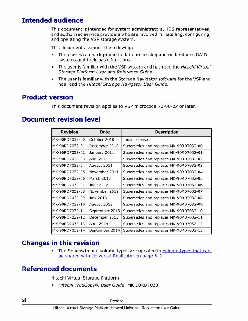
Document revision level
Changes in this revision• The ShadowImage volume types are updated in Volume types that can
be shared with Universal Replicator on page B-2.
Referenced documentsHitachi Virtual Storage Platform:• Hitachi TrueCopy® User Guide, MK-90RD7030
Revision Date Description
MK-90RD7032-00 October 2010 Initial release
MK-90RD7032-01 December 2010 Supersedes and replaces MK-90RD7032-00.
MK-90RD7032-02 January 2011 Supersedes and replaces MK-90RD7032-01.
MK-90RD7032-03 April 2011 Supersedes and replaces MK-90RD7032-02.
MK-90RD7032-04 August 2011 Supersedes and replaces MK-90RD7032-03.
MK-90RD7032-05 November 2011 Supersedes and replaces MK-90RD7032-04.
MK-90RD7032-06 March 2012 Supersedes and replaces MK-90RD7032-05.
MK-90RD7032-07 June 2012 Supersedes and replaces MK-90RD7032-06.
MK-90RD7032-08 November 2012 Supersedes and replaces MK-90RD7032-07.
MK-90RD7032-09 July 2013 Supersedes and replaces MK-90RD7032-08.
MK-90RD7032-10 August 2013 Supersedes and replaces MK-90RD7032-09.
MK-90RD7032-11 September 2013 Supersedes and replaces MK-90RD7032-10.
MK-90RD7032-12 December 2013 Supersedes and replaces MK-90RD7032-11.
MK-90RD7032-13 April 2014 Supersedes and replaces MK-90RD7032-12.
MK-90RD7032-14 September 2014 Supersedes and replaces MK-90RD7032-13.
Preface xiiiHitachi Virtual Storage Platform Hitachi Universal Replicator User Guide
• Hitachi ShadowImage® User Guide, MK-90RD7024• Hitachi Copy-on-Write Snapshot User Guide, MK-90RD7013• Hitachi Storage Navigator User Guide, MK-90RD7027• Hitachi Virtual Storage Platform User and Reference Guide, MK-
90RD7042• Hitachi Thin Image User Guide, MK-90RD7179
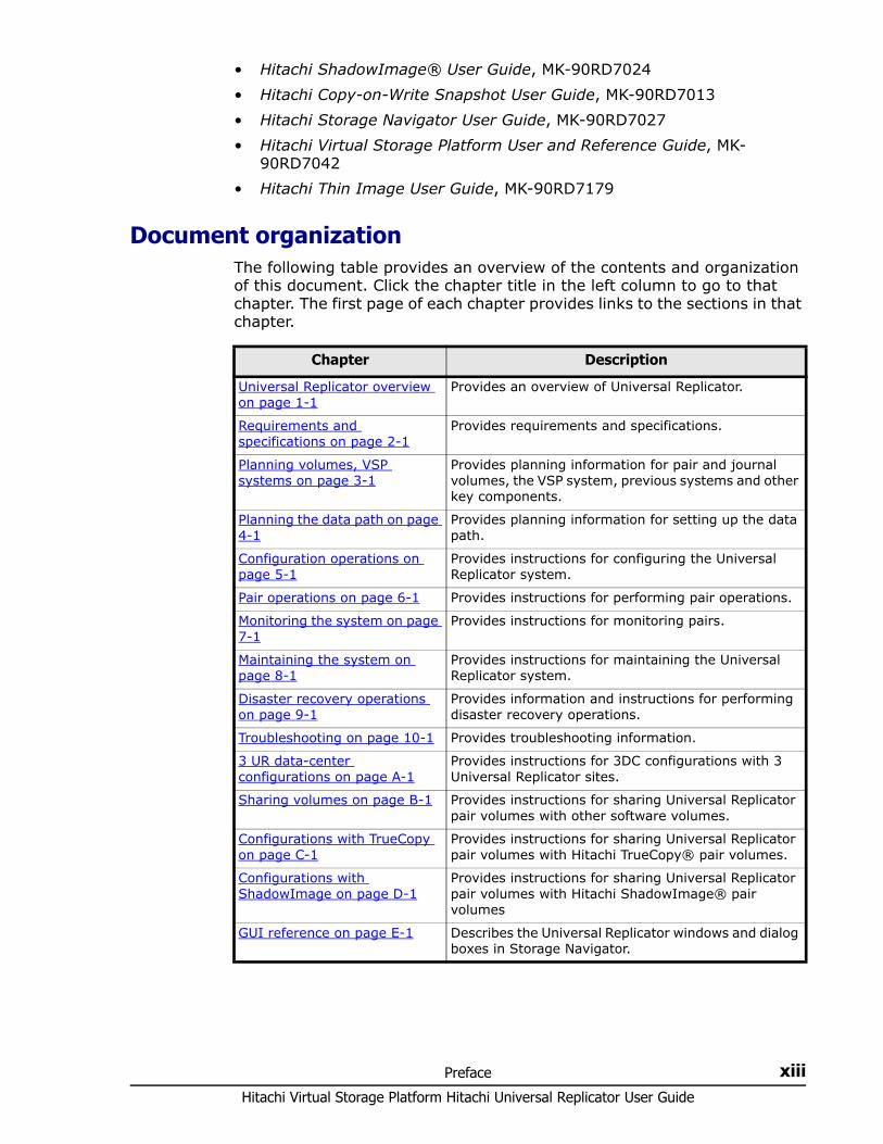
Document organizationThe following table provides an overview of the contents and organization of this document. Click the chapter title in the left column to go to that chapter. The first page of each chapter provides links to the sections in that chapter.
Chapter Description
Universal Replicator overview on page 1-1
Provides an overview of Universal Replicator.
Requirements and specifications on page 2-1
Provides requirements and specifications.
Planning volumes, VSP systems on page 3-1
Provides planning information for pair and journal volumes, the VSP system, previous systems and other key components.
Planning the data path on page 4-1
Provides planning information for setting up the data path.
Configuration operations on page 5-1
Provides instructions for configuring the Universal Replicator system.
Pair operations on page 6-1 Provides instructions for performing pair operations.
Monitoring the system on page 7-1
Provides instructions for monitoring pairs.
Maintaining the system on page 8-1
Provides instructions for maintaining the Universal Replicator system.
Disaster recovery operations on page 9-1
Provides information and instructions for performing disaster recovery operations.
Troubleshooting on page 10-1 Provides troubleshooting information.
3 UR data-center configurations on page A-1
Provides instructions for 3DC configurations with 3 Universal Replicator sites.
Sharing volumes on page B-1 Provides instructions for sharing Universal Replicator pair volumes with other software volumes.
Configurations with TrueCopy on page C-1
Provides instructions for sharing Universal Replicator pair volumes with Hitachi TrueCopy® pair volumes.
Configurations with ShadowImage on page D-1
Provides instructions for sharing Universal Replicator pair volumes with Hitachi ShadowImage® pair volumes
GUI reference on page E-1 Describes the Universal Replicator windows and dialog boxes in Storage Navigator.
Hitachi Virtual Storage Platform Hitachi Universal Replicator User Guide
xiv Preface
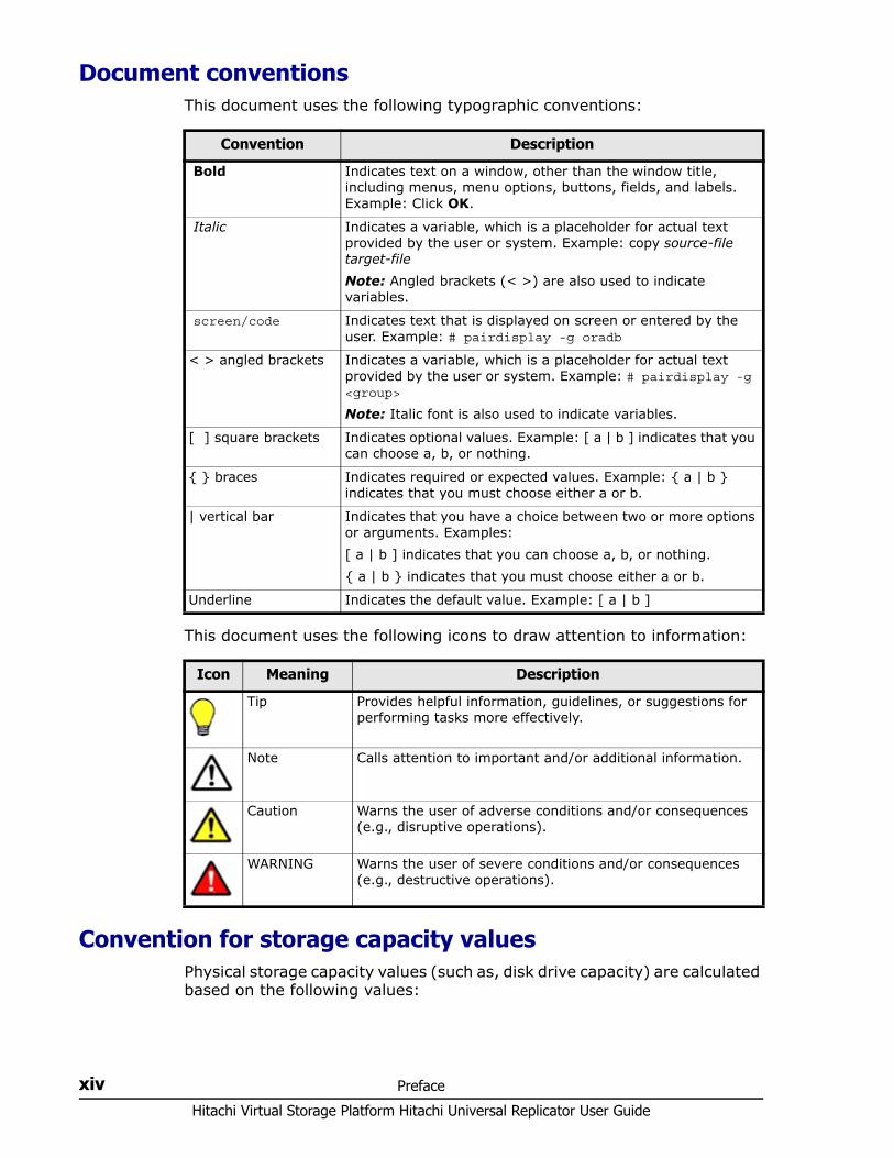
Document conventionsThis document uses the following typographic conventions:
This document uses the following icons to draw attention to information:
Convention for storage capacity valuesPhysical storage capacity values (such as, disk drive capacity) are calculated based on the following values:
Convention Description
Bold Indicates text on a window, other than the window title, including menus, menu options, buttons, fields, and labels. Example: Click OK.
Italic Indicates a variable, which is a placeholder for actual text provided by the user or system. Example: copy source-file target-file Note: Angled brackets (< >) are also used to indicate variables.
screen/code Indicates text that is displayed on screen or entered by the user. Example: # pairdisplay -g oradb
< > angled brackets Indicates a variable, which is a placeholder for actual text provided by the user or system. Example: # pairdisplay -g <group>
Note: Italic font is also used to indicate variables.
[ ] square brackets Indicates optional values. Example: [ a | b ] indicates that you can choose a, b, or nothing.
{ } braces Indicates required or expected values. Example: { a | b } indicates that you must choose either a or b.
| vertical bar Indicates that you have a choice between two or more options or arguments. Examples:[ a | b ] indicates that you can choose a, b, or nothing.{ a | b } indicates that you must choose either a or b.
Underline Indicates the default value. Example: [ a | b ]
Icon Meaning Description
Tip Provides helpful information, guidelines, or suggestions for performing tasks more effectively.
Note Calls attention to important and/or additional information.
Caution Warns the user of adverse conditions and/or consequences (e.g., disruptive operations).
WARNING Warns the user of severe conditions and/or consequences (e.g., destructive operations).

Preface xvHitachi Virtual Storage Platform Hitachi Universal Replicator User Guide
Logical storage capacity values (such as, logical device capacity) are calculated based on the following values:
Accessing product documentationThe VSP user documentation is available on the HDS Support Portal: https://Portal.HDS.com. Please check this site for the most current documentation, including important updates that may have been made after the release of the product.
Getting helpThe HDS customer support staff is available 24 hours a day, seven days a week. If you need technical support, log on to the HDS Support Portal for contact information: https://Portal.HDS.com
CommentsPlease send us your comments on this document: [email protected]. Include the document title, number, and revision. Please refer to specific sections and paragraphs whenever possible.
Thank you! (All comments become the property of HDS.)
Physical capacity unit Value
1 KB 1,000 bytes
1 MB 1,0002 bytes
1 GB 1,0003 bytes
1 TB 1,0004 bytes
1 PB 1,0005 bytes
1 EB 1,0006 bytes
Logical capacity unit Value
1 KB 1,024 bytes
1 MB 1,024 KB or 1,0242 bytes
1 GB 1,024 MB or 1,0243 bytes
1 TB 1,024 GB or 1,0244 bytes
1 PB 1,024 TB or 1,0245 bytes
1 EB 1,024 PB or 1,0246 bytes
1 block 512 bytes

Hitachi Virtual Storage Platform Hitachi Universal Replicator User Guide
xvi Preface
1
Universal Replicator overview 1–1Hitachi Virtual Storage Platform Hitachi Universal Replicator User Guide
Universal Replicator overview
With Hitachi Universal Replicator (UR), you create and maintain a remote copy of a data volume on a Hitachi Virtual Storage Platform (VSP) storage system.
This guide provides instructions for planning, configuring, operating, maintaining, and troubleshooting a Universal Replicator system.
□ Universal Replicator software
□ How Universal Replicator works
□ Hardware and software components
□ Reference Information
Hitachi Virtual Storage Platform Hitachi Universal Replicator User Guide
1–2 Universal Replicator overview
Universal Replicator software With Universal Replicator, you copy application data to a secondary VSP system at a remote location. The remote volume is an asynchronous block-for-block copy of the local storage volume. The copied data is consistent with local data and therefore available for recovering the local volume if the need arises.
Universal Replicator is designed to support a secondary site hundreds and even thousands of miles from the local site, making recovery from region-wide disasters possible.
Universal Replicator is also designed to limit impact on the local system. Updates sent from a host to the primary production volume on the local system are copied to a local journal volume. The remote system “pulls” data from the journal volume across the communication link to the backup-volume, called the secondary volume. The local system is free to perform its role as a transaction processing resource rather than as a replication engine.
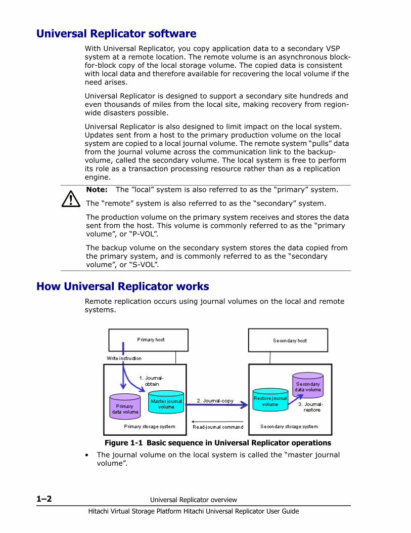
How Universal Replicator worksRemote replication occurs using journal volumes on the local and remote systems.
• The journal volume on the local system is called the “master journal volume”.
Note: The ”local” system is also referred to as the “primary” system.
The “remote” system is also referred to as the “secondary” system.
The production volume on the primary system receives and stores the data sent from the host. This volume is commonly referred to as the “primary volume”, or “P-VOL”.
The backup volume on the secondary system stores the data copied from the primary system, and is commonly referred to as the “secondary volume”, or “S-VOL”.
Figure 1-1 Basic sequence in Universal Replicator operations
Universal Replicator overview 1–3Hitachi Virtual Storage Platform Hitachi Universal Replicator User Guide
• The journal volume on the remote system is called the “restore journal volume”.
Replication occurs in the following sequence:1. Journal obtain - When the host sends an update to the primary volume
(P-VOL), the primary (local) system’s journal-obtain function triggers a copy of the updated data to the master journal volume. The host assigns write-sequence numbers to the data sent to the
master journal volume. Write-sequence numbers and other metadata attached to journal
data ensure consistency with the data in the P-VOL.2. Journal copy - Data is copied from the master journal to the restore
journal. When the master journal has data, the data is transferred to the
restore journal. When data transfer is complete, master journal data is discarded.
Data copy to the restore journal is initiated by the read-journal command issued by the remote system.
Data copy occurs on a continual basis unless there is no data in the master journal. The request for data from the remote system is repeated as soon as the previous read operation is completed.
Journal data is removed from the master journal only when the primary system receives sequence numbers for the data from the restore journal.
3. Journal-restore - The secondary volume (S-VOL) is updated with changed data from the restore journal. Data is copied to the S-VOL according to the write sequence
numbers, ensuring data consistency. When journal-restore is completed, the data in the restore journal is
discarded.
Performance is affected because of journal-to-journal copying. Usage rates are also affected. See Read and write I/O during remote copy on page 1-8 for more high level information on Universal Replicator operations.
Hardware and software componentsA typical configuration consists of a VSP system or externally attached storage system on both local and remote sites, a host or hosts connected to the systems, Universal Replicator software on both systems, data path connections, and interface tools for configuring and managing Universal Replicator. • The local and remote VSP systems are connected using dedicated fibre-
channel data paths that can include fibre-channel switches. Data paths are routed from the fibre-channel ports on the primary system to the ports on the secondary system.
• The host is connected to the VSP using a fibre-channel or fibre-channel-over-Ethernet (FCoE) target port.
Hitachi Virtual Storage Platform Hitachi Universal Replicator User Guide
1–4 Universal Replicator overview
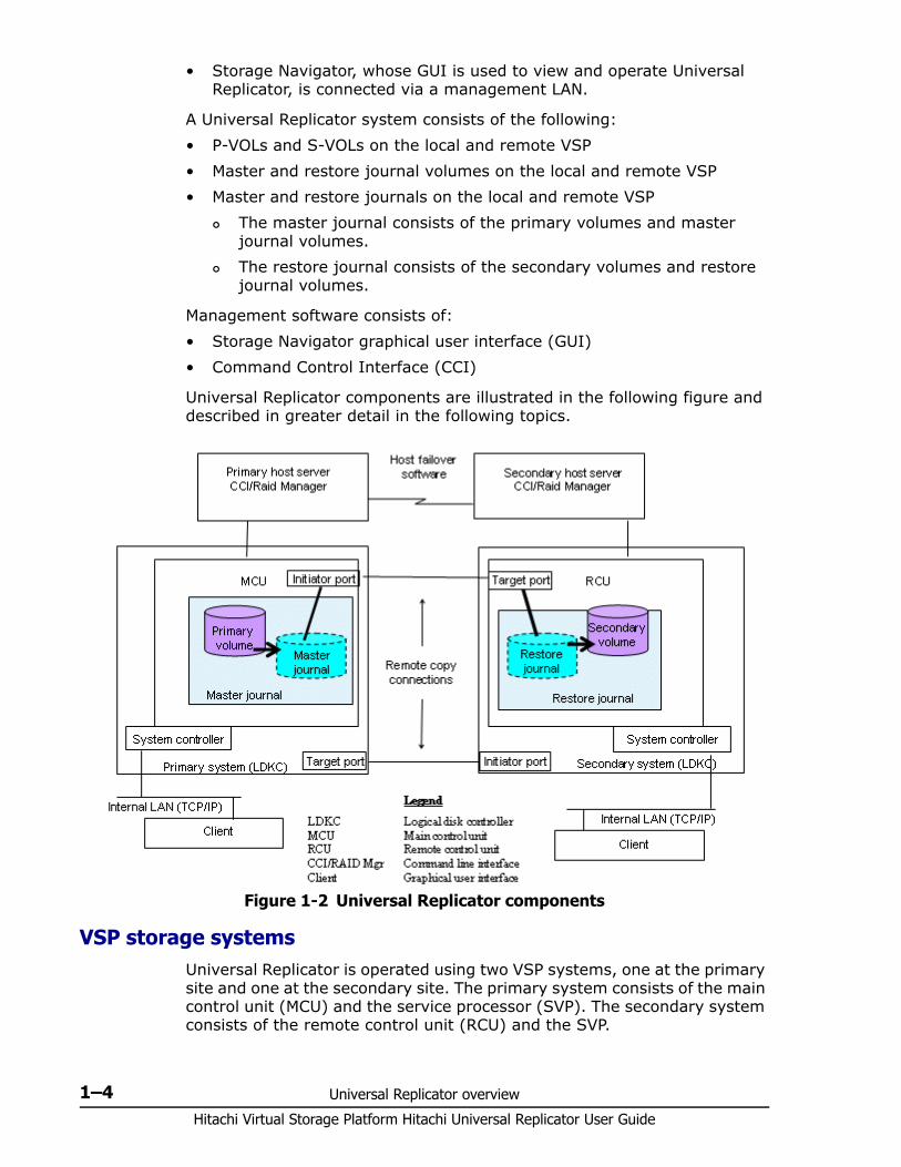
• Storage Navigator, whose GUI is used to view and operate Universal Replicator, is connected via a management LAN.
A Universal Replicator system consists of the following:• P-VOLs and S-VOLs on the local and remote VSP• Master and restore journal volumes on the local and remote VSP• Master and restore journals on the local and remote VSP
The master journal consists of the primary volumes and master journal volumes.
The restore journal consists of the secondary volumes and restore journal volumes.
Management software consists of:• Storage Navigator graphical user interface (GUI)• Command Control Interface (CCI)
Universal Replicator components are illustrated in the following figure and described in greater detail in the following topics.
VSP storage systemsUniversal Replicator is operated using two VSP systems, one at the primary site and one at the secondary site. The primary system consists of the main control unit (MCU) and the service processor (SVP). The secondary system consists of the remote control unit (RCU) and the SVP.
Figure 1-2 Universal Replicator components
Universal Replicator overview 1–5Hitachi Virtual Storage Platform Hitachi Universal Replicator User Guide
• The primary system communicates with the secondary system over dedicated fibre-channel remote copy connections.
• Each VSP system can function simultaneously as a primary and secondary system.
Main and remote control units
The primary and secondary systems are often referred to as the MCU (primary system) and RCU (secondary system). MCU is the main control unit, RCU is the remote control unit.
The MCU control the primary storage volume (P-VOL) and the following operations: • Host I/O write to the P-VOL• P-VOL data copy to the master journal • Initial copy and update copy between the P-VOL and secondary volume
(S-VOL).
The RCU control the secondary storage volume (S-VOL) and the following operations:• Journal commands to the MCU.• Journal data copy from the master to the restore journal • Restore journal data copy to the S-VOL• Pair status management and configuration (for example, rejecting write
I/Os to the S-VOLs).
Pair volumesOriginal data is stored in the P-VOL and the remote copy is stored in the S-VOL. The pair can be paired, split, re-synchronized, and returned to the unpaired (called “simplex”) state. When synchronized, the volumes are paired; when split, new or changed data sent to the P-VOL is not copied to the S-VOL. When re-synchronized, changed data is copied to the S-VOL. If a disaster occurs, production operations can be transferred to the S-VOL. When the primary site is functional again, operations can be transferred and data can be copied back to the P-VOL.
The P-VOL remains available to the host for read and write I/O operations. The secondary system rejects write I/Os for the S-VOL, unless the write-enable option is specified. Then, write I/O is allowed to the S-VOL while the pair is split. In this instance, S-VOL and P-VOL track maps keep track of differential data and use it to re-synchronize the pair.
Journal volumesFor Universal Replicator operations, journal volumes are required on the primary and secondary systems.• Updates to the P-VOL are copied to the master journal volume in the
primary system. See the illustration in Journals on page 1-6.
Hitachi Virtual Storage Platform Hitachi Universal Replicator User Guide
1–6 Universal Replicator overview
• Master journal data is copied to the restore journal volume on the secondary system.
• Journal volumes can have different volume sizes and different RAID configurations.
• Journal data is stored sequentially and separately in each journal volume in the same journal.
For information on planning journal volumes, see Sizing journal volumes on page 3-4 .
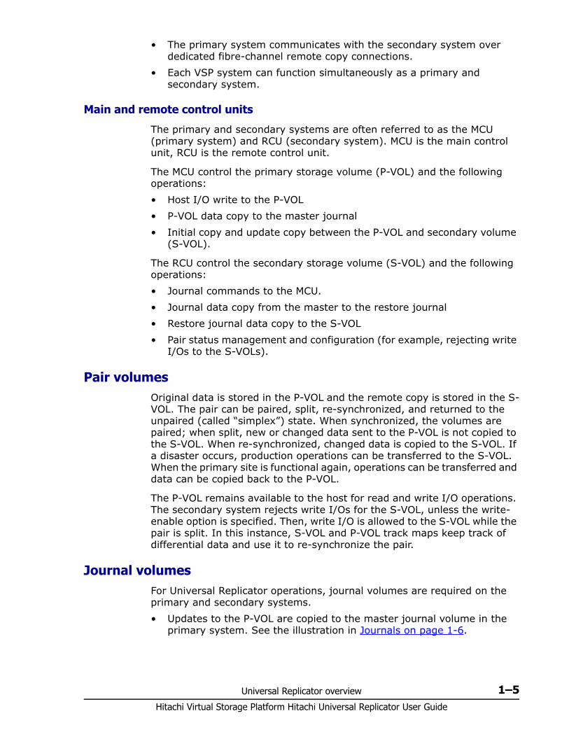
JournalsJournals help you manage data consistency between multiple P-VOLs and S-VOLs. A journal consists of two or more data volumes and journal volumes.
You use journals to create multiple pairs and to split, resynchronize, and release multiple pairs. Journals are required on the primary and secondary systems.
Each data volume and its associated journal volume reside in the same journal. • The master journal contains master journal volumes and is associated
with the P-VOL.• The restore journal contains restore journal volumes and is associated
with the S-VOL
Each pair relationship between journals is called a "mirror". A mirror ID identifies a pair relationship between journals. When the pair is created, it is assigned a mirror ID.
Figure 1-3 Journals
Universal Replicator overview 1–7Hitachi Virtual Storage Platform Hitachi Universal Replicator User Guide
Data pathThe physical transmission link between the local and remote systems is called the data path. Universal Replicator commands and data are transmitted through the fibre-channel data path and switches. The data path is connected to the primary and secondary systems through two types of fibre-channel ports, Initiator and RCU Target ports. Universal Replicator requires paths in both directions. More specifically, it requires paths with Initiator ports in the MCU connected to RCU Target ports in the RCU, and paths with Initiator Ports in the RCU connected to RCU Target ports in the MCU.
One data path connection is required. It is recommended that you use two or more independent connections to provide hardware redundancy. A maximum of eight paths can be used.
For more information, see Planning the data path on page 4-1.
Consistency groups and journalsJournals are used in Universal Replicator to guarantee data consistency across multiple pairs. Consistency groups are used in other replication software for the same purpose. As a best practice, you can assign CCI consistency group numbers as journal numbers. See “journals” in System requirements on page 2-2 and Multiple journals per CCI consistency group on page 3-14 for more information.
Storage Navigator Storage Navigator provides a GUI and command line interface for accessing and managing the storage system, including Universal Replicator.
Storage Navigator communicates with the SVP of each system over defined TCP/IP connections.
Command Control Interface (CCI)CCI provides a command line interface for accessing and managing the storage system, including Universal Replicator. You can perform the same Universal Replicator operations with CCI as you can with Storage Navigator. In addition, you can automate pair operations using scripts.
If you want to use CCI but it is not installed, contact your Hitachi Data Systems account team.
Reference InformationThe following topics describe UR copy operations and other features.
Overview of copy operationsinitial and update copy operations including the underlying operations, such as journal processing and differential data management.
Hitachi Virtual Storage Platform Hitachi Universal Replicator User Guide
1–8 Universal Replicator overview
Initial copy operation
The initial copy is executed when the primary system copies all the data in sequence from the P-VOL directly to the S-VOL. Though journal volumes are not used during the initial copy, the copy data in this operation is referred to as “base journal data”. • Creating or resynchronizing two or more pairs within the same journal
results in the base journal data being copied to the respective S-VOLs, one at a time. This extends the time required for all the operations to be completed.
• An initial copy operation can be performed to establish the pair — with no data copied between the volumes. This can be done when data in the P-VOLs and S-VOLs are identical.
• Universal Replicator pair data can also be copied using a TrueCopy initial copy operation. Doing this reduces the time to complete the copy operation. See Planning pair volumes on page 3-8 for more information.
Update copy operation
When a host has new or changed information, the following occurs in the primary system:• The update is written to the P-VOL• The update is copied to the master journal along with metadata that
includes sequence and other consistency information.The remote system issues the read-journal command (independent of host I/O activity). At this time, the following occurs: Any data in the master journal is sent to the restore journal. The updated data is copied to the S-VOL. Journal data on the primary and secondary systems is discarded
when data consistency is established in the copy.
If an update copy operation fails, the remote system suspends the affected pair or all pairs in the journal, depending on the type of failure. The suspended pair or journal returns to Paired status when the primary and secondary systems are re-synchronized.
Read and write I/O during remote copyThe primary system reads from the P-VOL when it receives a read I/O command. If the read fails, the redundancy provided by RAID-1 or RAID-5 technology recovers the failure. The primary system does not read the S-VOL for recovery.
Note: Journal data is transferred using special I/O operations initiated by the secondary system, called RIO (remote I/O). RIO provides the most efficient type of data transfer. Make sure that your channel extenders are capable of supporting RIO. Contact Hitachi Data Systems Support Center for more information.

Universal Replicator overview 1–9Hitachi Virtual Storage Platform Hitachi Universal Replicator User Guide
When a primary system receives a write I/O command for a P-VOL in PAIR status, the system performs the write operation and performs the update copy operation. The write operation completes independently of the update copy operations on the S-VOL.
The secondary system updates the S-VOL according to the write sequence number in the journal data. This maintains data consistency between P-VOL and S-VOL.
If the P-VOL write operation fails, the primary system reports a unit check and does not create the journal data for this operation. As mentioned, if the update copy operation fails, the secondary system suspends either the affected pair or all Universal Replicator pairs in the journal, depending on the type of failure. When the suspended pair or journal is resumed, the primary and secondary systems negotiate the resynchronization of the pairs.
During normal operations, the secondary system does not allow S-VOLs to be online (mounted). Therefore, hosts cannot read from and write to S-VOLs. However, if the S-VOL write option is enabled, write access to an S-VOL is allowed while the pair is split. The pair must be split from the primary system for the option to take effect.
To reduce the overhead associated with remote copy activities and to maximize rate of data transfer, the VSP uses a special write command for initial and update copy operations. This command transfers the control parameters and the fixed-block architecture (FBA) format data for consecutive updated records in a track using a single write operation. It eliminates the overhead required for performing FBA-to-count-key-data (CKD) and CKD-to-FBA conversions.
Differential data managementDifferential data is the data that is changed in the P-VOL when a pair is split or suspended and that is not reflected in the S-VOL. This data is stored in a track bitmap. When the pair is resynchronized, the primary system merges the P-VOL and S-VOL bitmaps, and the differential data is copied to the S-VOL.
The number of bitmap areas affects the maximum possible number of pairs that can be created in the system.
S-VOL write optionWhen splitting a pair, you can set an option allowing write I/O to the S-VOL. When you resynchronize a split pair whose S-VOL is write-enabled, the secondary system sends the S-VOL track bitmap to the primary system, which merges the P-VOL and S-VOL bitmaps to determine which tracks are out of sync. This ensures proper resynchronization of the pair.
Hitachi Virtual Storage Platform Hitachi Universal Replicator User Guide
1–10 Universal Replicator overview
Pair statusEvery pair operation results in a change in pair status. In addition, when you want to perform an operation, the pair must have a specific status in order to for the operation to run. You will monitor pair status to ensure that you can perform the desired operation, and to ensure that an operation completed successfully.
The following provides a brief description of the pair statuses. For complete details, see Pair status definitions on page 7-2 . • SMPL: A volume that is not assigned to a pair is in simplex status, SMPL.• COPY: When copy processing is started, the primary system changes
the status of the P-VOL and S-VOL to COPY.• PAIR: When the initial copy processing is complete, the primary system
changes the status of both data volumes to PAIR.• PSUE: When a pair is suspended due to an error condition, the primary
system changes the P-VOL and S-VOL status to PSUE (if the path status is normal).
• PSUS: When a pair is split by the user (pairsplit-r), the primary or secondary
system changes the status of the P-VOL and S-VOL to PSUS (if the path status is normal).
If a pair is split from the secondary system, it changes the S-VOL status to PSUS. The primary system detects the split (if path status is normal) and changes the P-VOL status to PSUS.
2
Requirements and specifications 2–1Hitachi Virtual Storage Platform Hitachi Universal Replicator User Guide
Requirements and specifications
This chapter provides system requirements for Hitachi Universal Replicator.
□ System requirements
Hitachi Virtual Storage Platform Hitachi Universal Replicator User Guide
2–2 Requirements and specifications
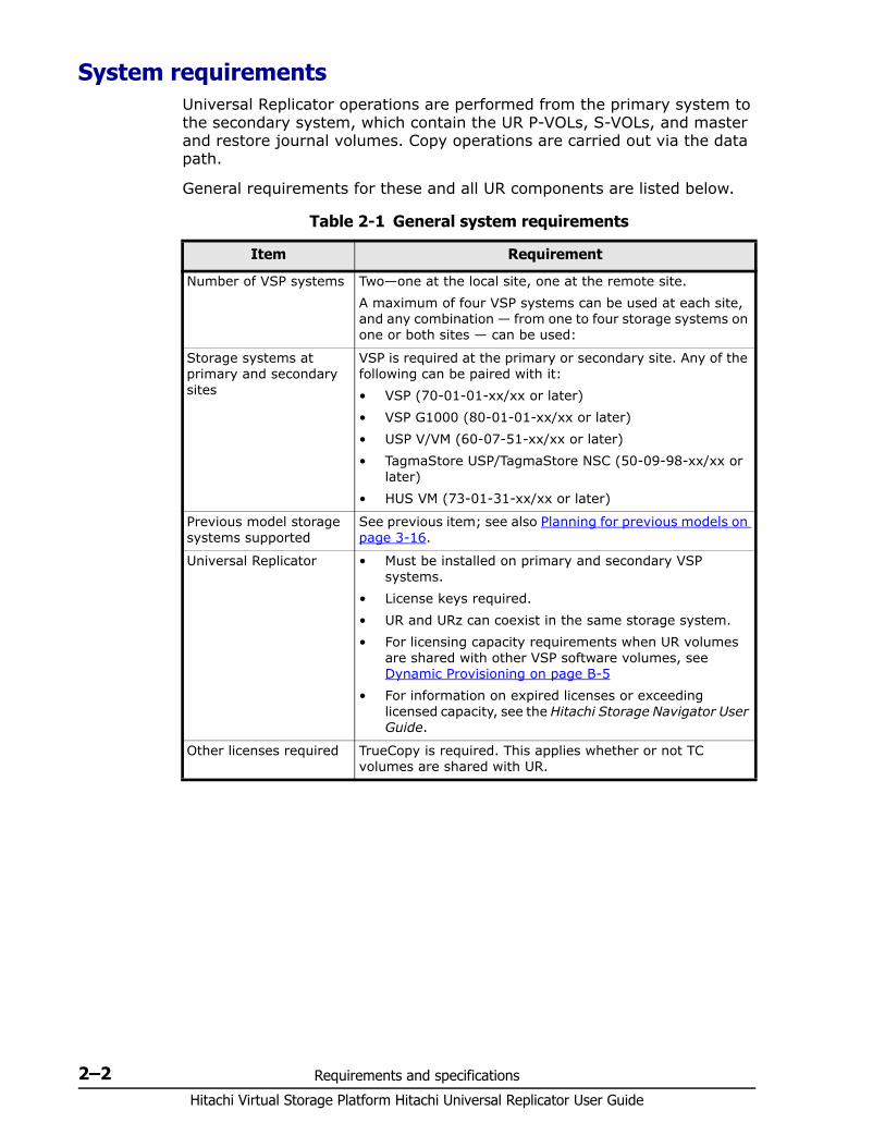
System requirementsUniversal Replicator operations are performed from the primary system to the secondary system, which contain the UR P-VOLs, S-VOLs, and master and restore journal volumes. Copy operations are carried out via the data path.
General requirements for these and all UR components are listed below.
Table 2-1 General system requirements
Item Requirement
Number of VSP systems Two—one at the local site, one at the remote site. A maximum of four VSP systems can be used at each site, and any combination — from one to four storage systems on one or both sites — can be used:
Storage systems at primary and secondary sites
VSP is required at the primary or secondary site. Any of the following can be paired with it:• VSP (70-01-01-xx/xx or later)• VSP G1000 (80-01-01-xx/xx or later)• USP V/VM (60-07-51-xx/xx or later)• TagmaStore USP/TagmaStore NSC (50-09-98-xx/xx or
later)• HUS VM (73-01-31-xx/xx or later)
Previous model storage systems supported
See previous item; see also Planning for previous models on page 3-16.
Universal Replicator • Must be installed on primary and secondary VSP systems.
• License keys required.• UR and URz can coexist in the same storage system.• For licensing capacity requirements when UR volumes
are shared with other VSP software volumes, see Dynamic Provisioning on page B-5
• For information on expired licenses or exceeding licensed capacity, see the Hitachi Storage Navigator User Guide.
Other licenses required TrueCopy is required. This applies whether or not TC volumes are shared with UR.
Requirements and specifications 2–3Hitachi Virtual Storage Platform Hitachi Universal Replicator User Guide
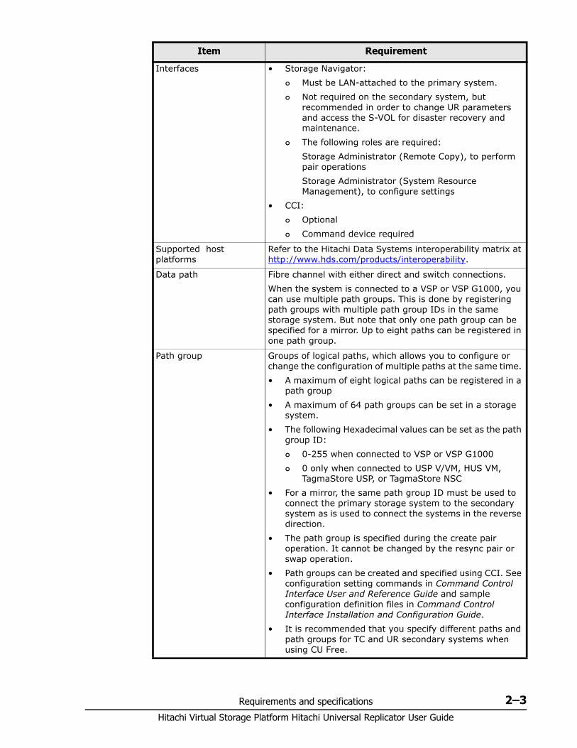
Interfaces • Storage Navigator: Must be LAN-attached to the primary system. Not required on the secondary system, but
recommended in order to change UR parameters and access the S-VOL for disaster recovery and maintenance.
The following roles are required:Storage Administrator (Remote Copy), to perform pair operationsStorage Administrator (System Resource Management), to configure settings
• CCI: Optional Command device required
Supported host platforms
Refer to the Hitachi Data Systems interoperability matrix at http://www.hds.com/products/interoperability.
Data path Fibre channel with either direct and switch connections.When the system is connected to a VSP or VSP G1000, you can use multiple path groups. This is done by registering path groups with multiple path group IDs in the same storage system. But note that only one path group can be specified for a mirror. Up to eight paths can be registered in one path group.
Path group Groups of logical paths, which allows you to configure or change the configuration of multiple paths at the same time. • A maximum of eight logical paths can be registered in a
path group• A maximum of 64 path groups can be set in a storage
system. • The following Hexadecimal values can be set as the path
group ID: 0-255 when connected to VSP or VSP G1000 0 only when connected to USP V/VM, HUS VM,
TagmaStore USP, or TagmaStore NSC• For a mirror, the same path group ID must be used to
connect the primary storage system to the secondary system as is used to connect the systems in the reverse direction.
• The path group is specified during the create pair operation. It cannot be changed by the resync pair or swap operation.
• Path groups can be created and specified using CCI. See configuration setting commands in Command Control Interface User and Reference Guide and sample configuration definition files in Command Control Interface Installation and Configuration Guide.
• It is recommended that you specify different paths and path groups for TC and UR secondary systems when using CU Free.
Item Requirement
Hitachi Virtual Storage Platform Hitachi Universal Replicator User Guide
2–4 Requirements and specifications
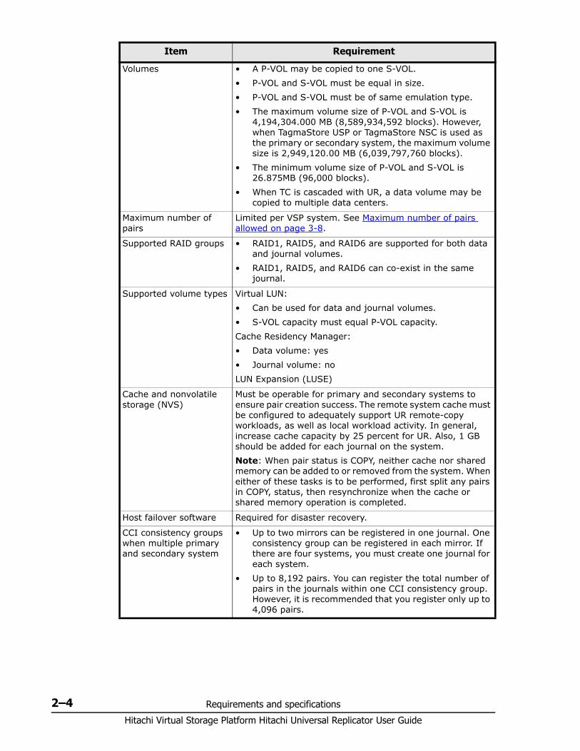
Volumes • A P-VOL may be copied to one S-VOL.• P-VOL and S-VOL must be equal in size. • P-VOL and S-VOL must be of same emulation type.• The maximum volume size of P-VOL and S-VOL is
4,194,304.000 MB (8,589,934,592 blocks). However, when TagmaStore USP or TagmaStore NSC is used as the primary or secondary system, the maximum volume size is 2,949,120.00 MB (6,039,797,760 blocks).
• The minimum volume size of P-VOL and S-VOL is 26.875MB (96,000 blocks).
• When TC is cascaded with UR, a data volume may be copied to multiple data centers.
Maximum number of pairs
Limited per VSP system. See Maximum number of pairs allowed on page 3-8.
Supported RAID groups • RAID1, RAID5, and RAID6 are supported for both data and journal volumes.
• RAID1, RAID5, and RAID6 can co-exist in the same journal.
Supported volume types Virtual LUN: • Can be used for data and journal volumes.• S-VOL capacity must equal P-VOL capacity.Cache Residency Manager:• Data volume: yes• Journal volume: noLUN Expansion (LUSE)
Cache and nonvolatile storage (NVS)
Must be operable for primary and secondary systems to ensure pair creation success. The remote system cache must be configured to adequately support UR remote-copy workloads, as well as local workload activity. In general, increase cache capacity by 25 percent for UR. Also, 1 GB should be added for each journal on the system.Note: When pair status is COPY, neither cache nor shared memory can be added to or removed from the system. When either of these tasks is to be performed, first split any pairs in COPY, status, then resynchronize when the cache or shared memory operation is completed.
Host failover software Required for disaster recovery.
CCI consistency groups when multiple primary and secondary system
• Up to two mirrors can be registered in one journal. One consistency group can be registered in each mirror. If there are four systems, you must create one journal for each system.
• Up to 8,192 pairs. You can register the total number of pairs in the journals within one CCI consistency group. However, it is recommended that you register only up to 4,096 pairs.
Item Requirement
Requirements and specifications 2–5Hitachi Virtual Storage Platform Hitachi Universal Replicator User Guide
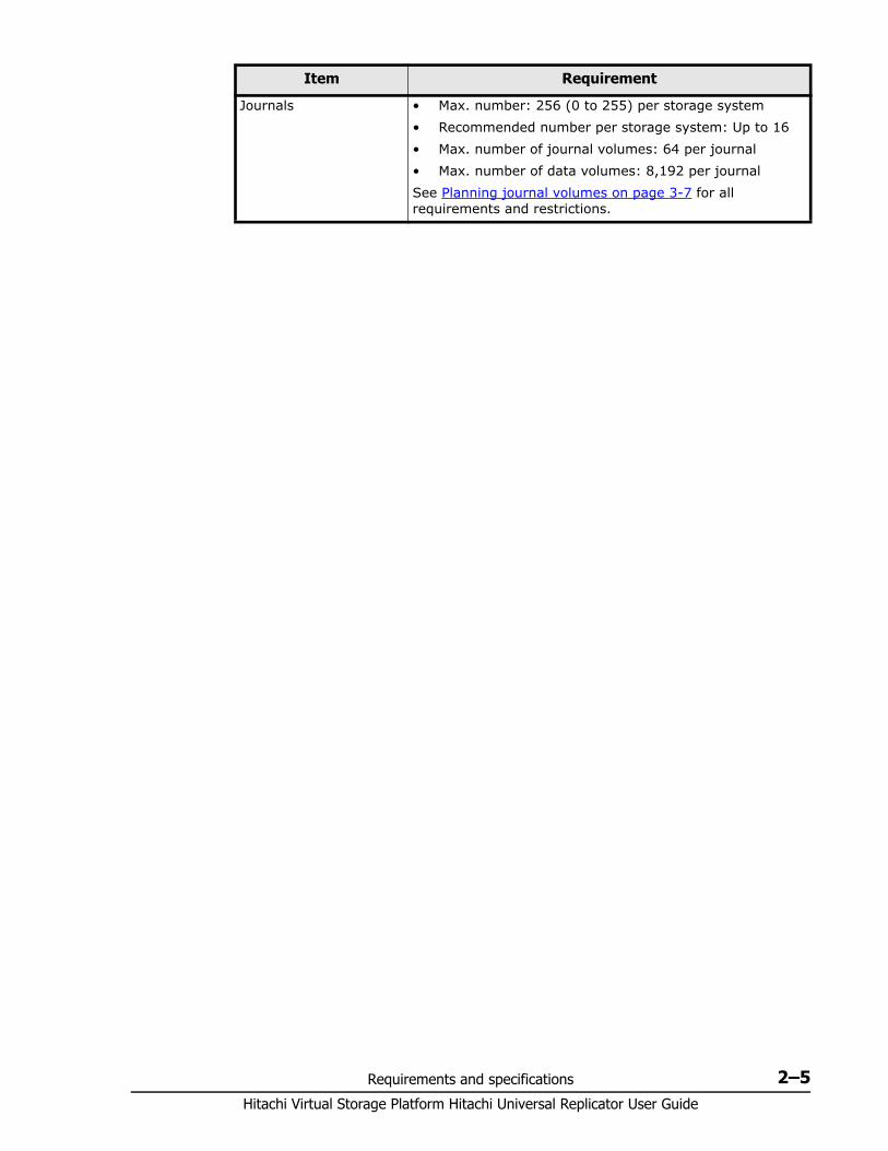
Journals • Max. number: 256 (0 to 255) per storage system• Recommended number per storage system: Up to 16• Max. number of journal volumes: 64 per journal • Max. number of data volumes: 8,192 per journal See Planning journal volumes on page 3-7 for all requirements and restrictions.
Item Requirement

Hitachi Virtual Storage Platform Hitachi Universal Replicator User Guide
2–6 Requirements and specifications
3
Planning volumes, VSP systems 3–1Hitachi Virtual Storage Platform Hitachi Universal Replicator User Guide
Planning volumes, VSP systems
This chapter provides information and instructions for planning Universal Replicator volumes, VSP systems, and other important requirements and restrictions.
□ Plan and design workflow
□ Assessing business requirements for data recovery
□ Write-workload
□ Sizing journal volumes
□ Planning journals
□ Data transfer speed considerations
□ Planning journal volumes
□ Planning pair volumes
□ Disaster recovery considerations
□ Sharing volumes with other VSP software volumes
□ Planning UR in multiple VSPs using a consistency group
□ Planning for previous models
□ Guidelines for preparing systems for UR
Hitachi Virtual Storage Platform Hitachi Universal Replicator User Guide
3–2 Planning volumes, VSP systems
Plan and design workflow Planning the Universal Replicator system is tied to your organization’s business requirements and production system workload. This means defining business requirements for disaster downtime and measuring the amount of changed data your storage system produces over time. With this information, you can calculate the size of journal volumes and the amount of bandwidth required to transfer update data over the data path network.
The plan and design workflow consists of the following:• Assess your organization’s business requirements to determine recovery
requirements.• Measure your host application’s write-workload in MB per second and
write-input/output per second (IOPS) to begin matching actual data loads with the planned UR system.
• Use collected data along with your organization’s recovery point objective (RPO) to size UR journal volumes. Journal volumes must have enough capacity to hold accumulating data over extended periods.The sizing of journal volumes can be influenced by the amount of bandwidth you settle on. Both efforts are interrelated. You may actually adjust journal volume size in conjunction with bandwidth to fit the organization’s needs.
• Use IOPS to determine data transfer speed into and out of the journal volumes. Data transfer speed is determined by the number of Fibre-Channel ports you assign to UR, and by RAID group configuration. You need to know port transfer capacity and the number of ports that your workload data will require.
• Use collected workload data to size bandwidth for the fibre-channel data path. As mentioned, bandwidth and journal volume sizing, along with data transfer speed, are interrelated. Bandwidth may be adjusted with the journal volume capacity and data transfer speed you plan to implement.
• Design the data path network configuration, based on supported configurations, fibre-channel switches, and the number of ports your data transfer requires.
• Plan data volumes (primary and secondary volumes), based on the sizing of P-VOL and S-VOL, RAID group considerations, and so on.
• Understand operating system requirements for data and journal volumes.
• Adjust cache memory capacity for UR.
Some tasks will be handled by HDS’ personnel. The planning information you need to address is provided in the following topics.
Planning volumes, VSP systems 3–3Hitachi Virtual Storage Platform Hitachi Universal Replicator User Guide
Assessing business requirements for data recovery In a UR system, when the data path continues to transfer changed data to the remote site, journals remain fairly empty. However, if a path failure or a prolonged spike in write-data that is greater than bandwidth occurs, data flow stops. Changed data that is no longer moving to the remote system builds up in the master journal.
To ensure that journals can hold the amount of data that could accumulate, they must be sized according to the following:• The maximum amount of time that journals could accumulate data. You
develop this information by determining your operation’s recovery point objective (RPO).
• The amount of changed data that your application generates. This is done by measuring write-workload.
Determining your RPO Your operation’s recovery point is the maximum time that can pass after a failure or disaster occurs before data loss is greater than the operation can survive.
For example, if the operation can survive one hour’s worth of lost data, and a disaster occurs at 10:00 am, then the system must be corrected by 11 a.m.
In regards to journal sizing, the journal must have the capacity to hold the data that could accumulated in one hour. If RPO is 4 hours, then the journal must be sized to hold 4-hour’s worth of accumulating data.
To assess RPO, the host application’s write-workload must be known.
With write-workload and IOPS, you or your organization’s decision-makers can analyze the number of transactions write-workload represents, determine the number of transactions the operation could loose and still remain viable, determine the amount of time required to recover lost data from log files or key it in, and so on. The result is your RPO.
Write-workload Write-workload is the amount of data that changes in your production system in MB per second. As you will see, write-workload varies. according to the time of day, week, month, quarter. That is why workload is measured over an extended period.
With the measurement data, you can calculate workload averages, locate peak workload, and calculate peak rolling averages, which show an elevated average. With one of these base data you will calculate the amount of data that accumulates over your RPO time, for example, 2 hours. This will be a base capacity for your journal volumes or represent a base amount of bandwidth your system requires.
Hitachi Virtual Storage Platform Hitachi Universal Replicator User Guide
3–4 Planning volumes, VSP systems
Whether you select average, rolling average, or peak workload is based on the amount of bandwidth you will provide the data path (which is also determined by write-workload). Bandwidth and journal volume capacity work together and depend on your strategy for protecting data.
Measuring write-workloadWorkload data is collected using Hitachi Performance Monitor or your operating system’s performance-monitoring feature. The number of read/write transactions, or input/output per second (IOPS), is also collected by the software. You will use IOPS to set up a proper data transfer speed, which you ensure through RAID group configuration and by establishing the number of fibre-channel ports your UR system requires. Each RAID group has a maximum transaction throughput; the ports and their microprocessors have an IOPS threshold.
Workload and IOPS collection is best performed during the busiest time of month, quarter, and year. This helps you to collect data that shows your system’s actual workloads during high peaks and spikes, when more data is changing, and when the demands on the system are greatest. Collecting data over these periods ensures that the UR design you develop will support your system in all workload levels.
To measure write-workload and IOPS1. Using your performance monitoring software, collect the following:
Disk-write bytes-per-second (MB/s) for every physical volume that will be replicated.
Data should be collected over a 3 or 4-week period to cover a normal, full business cycle.
Data should be collected at 5 minute intervals. If you use averages, shorter intervals provide more accuracy.
2. At the end of the collection period, convert the data to MB/second, if needed, and import into a spreadsheet tool.
Sizing journal volumes You calculate the size of your journal volumes using write-workload and RPO.
To calculate journal size1. Follow the instructions for Measuring write-workload on page 3-4.2. Use your system’s peak write-workload and your organization’s RPO to
calculate journal size. For example:RPO = 2 hours
Write-workload = 30 MB/sec
Calculate write-workload for the RPO. In the example, write-workload over a two-hour period is calculated as follows:30 MB/second x 60 seconds = 1800 MB/minute
1800 MB/minute x 60 minutes = 108,000 MB/hour
Planning volumes, VSP systems 3–5Hitachi Virtual Storage Platform Hitachi Universal Replicator User Guide
108000 MB/hour x 2 = 416,000 MB/2 hours
Basic journal volume size = 416,000 MB (416 GB)
Journal volume capacity and bandwidth size work together. Also, your strategy for protecting your data may allow you to adjust bandwidth or the size of your journal volumes. For a discussion on sizing strategies, see Five sizing strategies on page 4-2.
Planning journals UR manages pair operations for data consistency through the use of journals. UR journals enable update sequence consistency to be maintained across a group of volumes.
Understanding the consistency requirements for an application (or group of applications) and their volumes will indicate how to structure journals.
For example, databases are typically implemented in two sections. The bulk of the data is resident in a central data store, while incoming transactions are written to logs that are subsequently applied to the data store.
If the log volume “gets ahead” of the data store, it is possible that transactions could be lost at recovery time. Therefore, to ensure a valid recovery image on a replication volume, it is important that both the data store and logs are I/O consistent by placing them in the same journal.
The following information about journal volumes and journals will help you plan your journals.• A journal consists of one or more journal volumes and associated data
volumes.• A journal can have only P-VOLs/master journals, or S-VOLs/restore
journals.• A journal cannot belong to more than one storage system (local or
remote).• All the P-VOLs, or S-VOLs, in a journal must belong to the same storage
system.• Journal numbers of master and restore journals that are paired can be
different.If using a consistency group number, the consistency group number of the P-VOL and S-VOL must be the same.
• Each pair relationship in a journal is called a "mirror". Each pair is assigned a mirror ID. The maximum number of mirror IDs is 4 (0 to 3) per system.
• When UR and URz are used in the same system, individual journals must be dedicated either to one or the other, not both.
Note: If you are planning for disaster recovery, the remote system must be large enough to handle the production workload, and therefore, must be the same size as master journals. If not planning a disaster recovery solution, remote journal volumes may be smaller than master journal volumes.
Hitachi Virtual Storage Platform Hitachi Universal Replicator User Guide
3–6 Planning volumes, VSP systems
• Master and restore journals are managed according to the journal number.
• Review journal specifications in System requirements on page 2-2. • A journal can contain up to 64 journal volumes.
Data transfer speed considerations The previous topics and the topics later in this chapter on bandwidth discuss the amount of data that must be stored temporarily in journals volumes and transferred over the data path network. This topic discusses the speed that data must be transferred in order to maintain the UR system your are designing.
The ability of your UR system to transfer data in a timely manner depends directly on the following two factors:• RAID group configuration• Fibre-channel port configuration
Both of these elements must be planned to be able to handle the amount of data and number of transactions your system will move under extreme conditions.
RAID group configuration A RAID group can consist of physical volumes with a different number of revolutions, physical volumes of different capacities, and physical volumes of different RAID configurations (for example, RAID-1 and RAID-5). The data transfer speed of RAID groups is affected by physical volumes and RAID configurations.• The data transfer speed of a journal volume depends on the data
transfer speed of the RAID group to which it belongs. A RAID group can consist of one or more volumes, including journal volumes.
• Each RAID group has a different throughput rating. The number of MB/sec that volumes in a RAID group are capable of processing is published in UR specifications.
• Journal volumes must be configured in RAID groups according to the group’s throughput specification and your system’s peak write-workload. If write-workload exceeds the RAID group’s throughput rating, then the number of RAID groups must be increased.
• Frequent read/write activity to non-journal volumes in a RAID group results in fewer read/writes by journal volumes in the same RAID group. This can cause a drop in the data transfer speed of journal volumes. To avoid this effect, place journal volumes and frequently accessed non-journal volumes in different RAID groups.
Planning volumes, VSP systems 3–7Hitachi Virtual Storage Platform Hitachi Universal Replicator User Guide
Fibre-channel port configurationThe fibre-channel ports on your VSP system have an IOPS threshold. Use the performance monitoring information for the number of IOPS your production system generates to calculate the number of fibre-channel ports the UR system requires.
Please see Planning ports for data transfer on page 4-7 for a full discussion on the type and number of fibre-channel ports required for your system.
Planning journal volumes In addition to sizing journal volumes, you should be aware of the following requirements and restrictions. • Journal volumes must be registered in a journal before the initial pair-
copy operation is performed.• Journal volumes must be registered on both the local and remote
systems.• Emulation type for journal volumes must be OPEN-V. • Journal volumes should be sized according to RPO and write-workload.
See Sizing journal volumes on page 3-4 for more information.• If a path is defined from a host to a volume, the volume cannot be
registered as a journal volume.• Journal volumes in a journal can have different capacities. • A master journal volume and the corresponding restore journal volume
can have different capacities.• A data volume and its associated journal volume can belong to only one
journal.• Do not register a volume to a journal during quick formatting. Doing so
stalls the operation.• Data volumes and journal volumes in the same journal must belong to
the same controller.• The number of journal volumes in the master journal does not have to
be equal to the number of volumes in the restore journal.• Journal volumes consist of two areas: One area is used for storing
journal data, and the other area is used for storing metadata for remote copy.
• Journal volumes support all RAID configurations and physical volumes that are supported by VSP.
• Journal volume capacity is not included in accounting capacity. • Customized volumes can be used for journal volumes.
See the following for more information about journals and journal volumes:• The “Journals” item in System requirements on page 2-2• Planning journals on page 3-5
Hitachi Virtual Storage Platform Hitachi Universal Replicator User Guide
3–8 Planning volumes, VSP systems
Planning pair volumes The following information can help you prepare volumes for configuration. Also, see system requirements and specifications in Requirements and specifications on page 2-1 for more information.• The emulation and capacity for the S-VOL must be the same as for the
P-VOL• When the S-VOL is connected to the same host as the P-VOL, the S-VOL
must be defined to remain offline.• You can create a UR pair using a TrueCopy initial copy, which takes less
time. To do this, system option 474 must be set on the primary and secondary systems. Also, a script is required to perform this operation. For more on system option 474 and how to do this operation, see System option modes on page 3-18.
• UR supports the LUN Expansion (LUSE) feature, which allows you to configure a LUSE volume by using 2 to 36 sequential LDEVs. If two LUSE volumes are assigned to a UR pair, the capacity and configuration of the UR S-VOL must be the same as the UR P-VOL. For example, when the P-VOL is a LUSE volume in which 1-GB, 2-GB, and 3-GB volumes are combined in this order, the S-VOL must be a LUSE volume in which 1-GB, 2-GB, and 3-GB volumes are combined in this order. In addition, RAID1, RAID5, and RAID6 can coexist in the LUSE volume.
• UR supports the Virtual LUN feature, which allows you to configure custom LUs that are smaller than standard LUs. When custom LUs are assigned to a UR pair, the S-VOL must have the same capacity as the P-VOL. For details about Virtual LUN feature, see the Provisioning Guide for Open Systems.
• Identify the volumes that will become the P-VOLs and S-VOLs. Note the port, group ID (GID), and LUN of each volume. This information is used during the initial copy operation.
• You can create multiple pairs at the same time. Review the prerequisites and steps in Creating the initial copy on page 6-2.
• When you create a UR pair, you will have the option to create only the relationship, without copying data from P-VOL to S-VOL. You can use this option only when data in the two volumes is identical.
• When configuring the pair, best practice is to specify different serial numbers for the primary and secondary systems.
Maximum number of pairs allowed You can create up to 32,768 pairs on a VSP system. The maximum number for your system is limited by:• The number of cylinders in the volumes.
Planning volumes, VSP systems 3–9Hitachi Virtual Storage Platform Hitachi Universal Replicator User Guide
• The number of bitmap areas required for Universal Replicator data and journal volumes. This is calculated using the number of cylinders.
Calculating maximum number of pairs
To calculate the number of cylinders
Use the following formula:
Number of cylinders = (ceil ( (ceil (number of logical blocks / 512) ) /15) )
To calculate the number of required bitmap areas:
Use the following formula
ceil((number of cylinders x 15) / 122,752) )
where:• number of cylinders x 15 indicates the number of slots• 122,752 is the number of slots that a bitmap area can manage
To calculate the maximum number of pairs
The maximum number of pairs is determined by the following:
Caution: The bitmap areas that are used for Universal Replicator are also used for Universal Replicator for Mainframe, TrueCopy, TrueCopy for Mainframe, and High Availability Manager. If you use UR with any of these products, use the total number of each pair’s bitmap areas to calculate the maximum number of pairs. In addition, if UR and TC share the same volume, use the total number of both pairs regardless of whether the shared volume is primary or secondary.
Note: In the calculations below, note the following:• ceil () indicates that the value between the parentheses should be
rounded up to the nearest integer.• Number of logical bloxcks - Volume capacity (in bytes) / 512
Note: Doing this calculation for multiple volumes can result in inaccuracies. Perform the calculation for each volume seperately, then total the bitmap areas. The following examples show correct and incorrect calculations. Two volumes are used: one of 10,017 cylinders and another of 32,760 cylinders
Correct calculation
ceil ((10,017 x 15) / 122,752) = 2 ceil ((32,760 x 15) / 122,752) = 5 Total: 7
Incorrect calculation
10,017 + 32,760 = 42,777 cylinders ceil ((42,777 x 15) / 122,752) = 6
Note: If using LUSE volumes, add 1 to the required number of bitmap areas calculated in the formula above.

Hitachi Virtual Storage Platform Hitachi Universal Replicator User Guide
3–10 Planning volumes, VSP systems
• The number of bitmap areas required for Universal Replicator (calculated above).
• The total number of bitmap areas in the storage system, which is 65,536. Bitmap areas reside in an additional shared memory, which is required for Universal Replicator. Bitmap areas are used not only by Universal Replicator, but also by
Universal Replicator for Mainframe, TrueCopy, TrueCopy for Mainframe, and High Availability Manager. Therefore, the number of bitmap areas used by these other program products (if any) must be subtracted from 65,536, with the difference used to calculate the maximum number of pairs for Universal Replicator.
If TrueCopy and Universal Replicator share the same volume, you must use the total number of bitmap areas for both pairs regardless of whether the shared volume is main or remote.
• The maximum number of pairs supported per storage system, which is 32,768. If CCI is used, it is 32,767.
Calculate the maximum number of pairs using the following formula.
Maximum number of pairs = floor( Number of bitmap areas / required number of bitmap areas )
If the calculated maximum number of pairs exceeds the total number of LDEVs, and the total LDEVs are less than 32,768, then the total LDEV number is the maximum number of pairs that can be created.
Maximum initial copy operations and prioritiesDuring configuration, you specify the maximum number of initial copies that can be run at one time. The system allows up to 128 initial copies to run concurrently. You do this for performance reasons (the more initial copies running concurrently, the slower the performance).
You will also specify the priority for each initial copy during the create pair operation. Priority is used when you are creating multiple initial copies during an operation. Creating multiple initial copies in one operation is possible because you can specify multiple P-VOLs and S-VOLs in the Paircreate dialog box. The pair with priority 1 runs first, and so on up to 256.
When you create more pairs than the maximum initial copy setting, the pairs with priorities within the maximum number specified run concurrently, while the pairs with priorities higher than the maximum number wait. When one pair completes, a waiting pair begins, and so on.
If you perform a pair operation for multiple pairs (for a specific kind of data, for example), and then perform another operation for multiple pairs (for another specific kind of data, for example), the pairs in the first operation are completed in the order of their assigned priorities. The system begins processing pairs in the second set when the number of pairs left in the first set drops below the maximum number of initial copy-setting. This is shown in the following example.
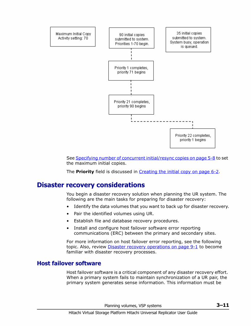
Planning volumes, VSP systems 3–11Hitachi Virtual Storage Platform Hitachi Universal Replicator User Guide
See Specifying number of concurrent initial/resync copies on page 5-8 to set the maximum initial copies.
The Priority field is discussed in Creating the initial copy on page 6-2.
Disaster recovery considerations You begin a disaster recovery solution when planning the UR system. The following are the main tasks for preparing for disaster recovery:• Identify the data volumes that you want to back up for disaster recovery.• Pair the identified volumes using UR.• Establish file and database recovery procedures.• Install and configure host failover software error reporting
communications (ERC) between the primary and secondary sites.
For more information on host failover error reporting, see the following topic. Also, review Disaster recovery operations on page 9-1 to become familiar with disaster recovery processes.
Host failover software Host failover software is a critical component of any disaster recovery effort. When a primary system fails to maintain synchronization of a UR pair, the primary system generates sense information. This information must be
Hitachi Virtual Storage Platform Hitachi Universal Replicator User Guide
3–12 Planning volumes, VSP systems
transferred to the remote site using the host failover software for effective disaster recovery. CCI provides failover commands that interface with industry-standard failover products.
Sharing volumes with other VSP software volumesUniversal Replicator volumes can be shared with other product volumes. Sharing pair volumes enhances replication solutions, for example, when Universal Replicator and TrueCopy or ShadowImage volumes are shared.
For planning information, see the following:• Sharing volumes on page B-1 • Configurations with TrueCopy on page C-1• Configurations with ShadowImage on page D-1
Planning UR in multiple VSPs using a consistency groupCopy operations can be run simultaneously on multiple UR pairs residing in multiple primary and multiple secondary systems. This is done by placing journals in the primary systems in a CCI consistency group. Data update order in copy processing is guaranteed to the secondary systems.
With multiple systems, the journals in the paired secondary systems are automatically placed in the consistency group.
With multiple systems, you can also place the journals from both OPEN and mainframe systems in the same CCI consistency group. When this configuration is used, URz journals cannot be placed in an EXCTG.
In addition, Universal Replicator volumes in multiple systems can be shared with other UR pairs and with TrueCopy pairs. See the following for more information:• 3 UR data-center configurations on page A-1• Configurations with TrueCopy on page C-1
You can register up to four journals in a single consistency group.
Any combination of primary and secondary system journals can be used. For example, you can include journals from four primary systems and four secondary systems, two primary systems and one secondary system, and so on.
An example configuration is shown in the following figure.
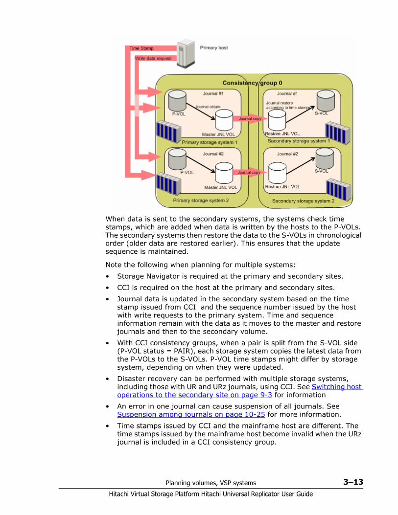
Planning volumes, VSP systems 3–13Hitachi Virtual Storage Platform Hitachi Universal Replicator User Guide
When data is sent to the secondary systems, the systems check time stamps, which are added when data is written by the hosts to the P-VOLs. The secondary systems then restore the data to the S-VOLs in chronological order (older data are restored earlier). This ensures that the update sequence is maintained.
Note the following when planning for multiple systems:• Storage Navigator is required at the primary and secondary sites.• CCI is required on the host at the primary and secondary sites.• Journal data is updated in the secondary system based on the time
stamp issued from CCI and the sequence number issued by the host with write requests to the primary system. Time and sequence information remain with the data as it moves to the master and restore journals and then to the secondary volume.
• With CCI consistency groups, when a pair is split from the S-VOL side (P-VOL status = PAIR), each storage system copies the latest data from the P-VOLs to the S-VOLs. P-VOL time stamps might differ by storage system, depending on when they were updated.
• Disaster recovery can be performed with multiple storage systems, including those with UR and URz journals, using CCI. See Switching host operations to the secondary site on page 9-3 for information
• An error in one journal can cause suspension of all journals. See Suspension among journals on page 10-25 for more information.
• Time stamps issued by CCI and the mainframe host are different. The time stamps issued by the mainframe host become invalid when the URz journal is included in a CCI consistency group.
Hitachi Virtual Storage Platform Hitachi Universal Replicator User Guide
3–14 Planning volumes, VSP systems
• Restoring data to the secondary system is performed when the time stamp of the copied journal is updated. The recommended interval between time stamps is one second.Consider the following before setting the interval: I/O response time slows when time stamps are updating among
multiple storage systems. If you shorten the interval, more time stamps are issued, resulting in an I/O response time that is slower yet.
If the interval is lengthened, the amount of time that journal data can accumulate increases, which results in an increased amount of data to be copied.
None of the above is true during the initial copy or resynchronization. During these operations, lengthening the interval between time stamps does not result in more accumulated journal data, because data restoring takes place regardless of time stamp.
• The recommended method for executing CCI commands is the in-band (host-based) method. This prevents I/O response from deteriorating, which may occur with the out-of-band (LAN-based) method.
• Do not register a URz journal in an EXCTG if it is included in a CCI consistency group. A journal is automatically released from the EXCTG when the CCI pair resynchronization operation is performed.
• In a CCI consistency group containing both UR and URz journals, data consistency is maintained in a UR system when its storage system’s microcode is changed to a version previous to 70-03-0x. However, you cannot lower the microcode for the URz storage system.
• It is not possible to register a journal to multiple CCI consistency groups.
Multiple journals per CCI consistency group Normally, only one journal can be registered in a CCI consistency group. With multiple VSP systems, however, up to four journals, including URz and UR journals, can be registered in a CCI consistency group. The following figures show different configurations in which multiple journals are registered in a single CCI consistency group.
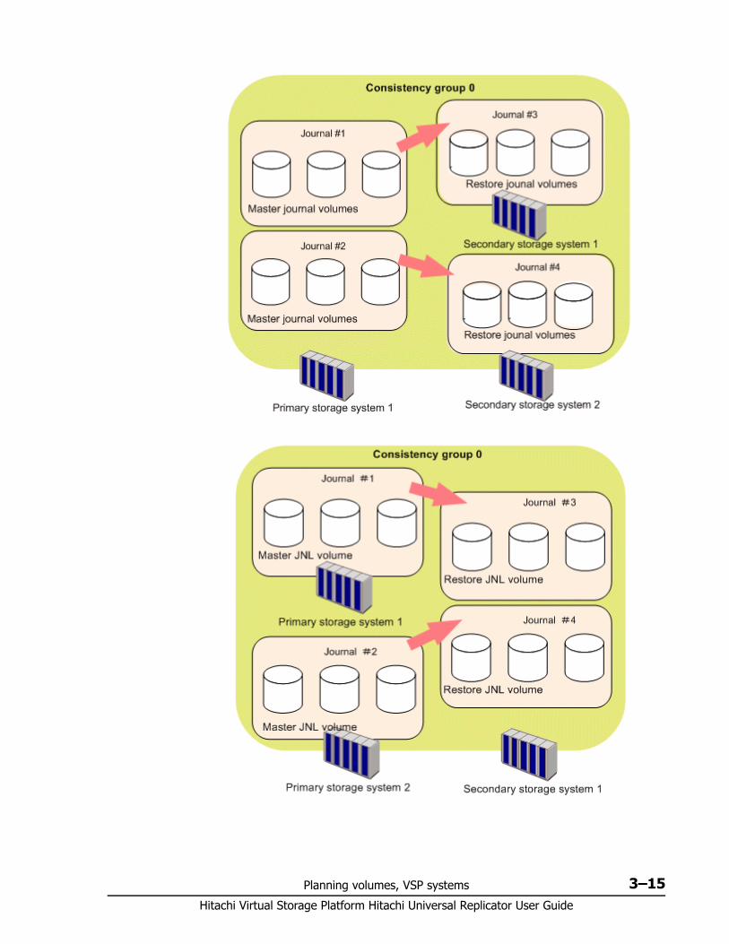
Planning volumes, VSP systems 3–15Hitachi Virtual Storage Platform Hitachi Universal Replicator User Guide
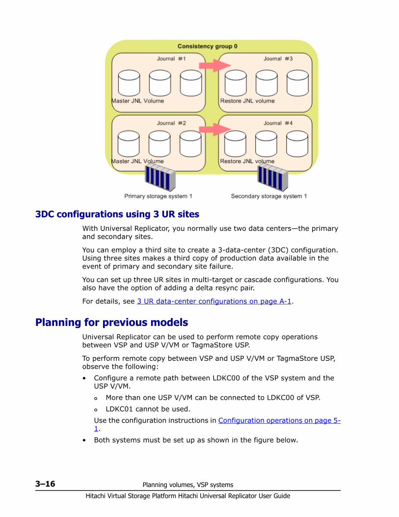
Hitachi Virtual Storage Platform Hitachi Universal Replicator User Guide
3–16 Planning volumes, VSP systems
3DC configurations using 3 UR sitesWith Universal Replicator, you normally use two data centers—the primary and secondary sites.
You can employ a third site to create a 3-data-center (3DC) configuration. Using three sites makes a third copy of production data available in the event of primary and secondary site failure.
You can set up three UR sites in multi-target or cascade configurations. You also have the option of adding a delta resync pair.
For details, see 3 UR data-center configurations on page A-1.
Planning for previous models Universal Replicator can be used to perform remote copy operations between VSP and USP V/VM or TagmaStore USP.
To perform remote copy between VSP and USP V/VM or TagmaStore USP, observe the following:• Configure a remote path between LDKC00 of the VSP system and the
USP V/VM. More than one USP V/VM can be connected to LDKC00 of VSP. LDKC01 cannot be used.
Use the configuration instructions in Configuration operations on page 5-1.
• Both systems must be set up as shown in the figure below.
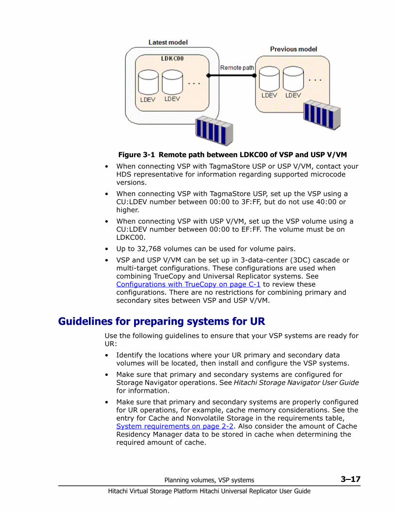
Planning volumes, VSP systems 3–17Hitachi Virtual Storage Platform Hitachi Universal Replicator User Guide
• When connecting VSP with TagmaStore USP or USP V/VM, contact your HDS representative for information regarding supported microcode versions.
• When connecting VSP with TagmaStore USP, set up the VSP using a CU:LDEV number between 00:00 to 3F:FF, but do not use 40:00 or higher.
• When connecting VSP with USP V/VM, set up the VSP volume using a CU:LDEV number between 00:00 to EF:FF. The volume must be on LDKC00.
• Up to 32,768 volumes can be used for volume pairs.• VSP and USP V/VM can be set up in 3-data-center (3DC) cascade or
multi-target configurations. These configurations are used when combining TrueCopy and Universal Replicator systems. See Configurations with TrueCopy on page C-1 to review these configurations. There are no restrictions for combining primary and secondary sites between VSP and USP V/VM.
Guidelines for preparing systems for UR Use the following guidelines to ensure that your VSP systems are ready for UR:• Identify the locations where your UR primary and secondary data
volumes will be located, then install and configure the VSP systems.• Make sure that primary and secondary systems are configured for
Storage Navigator operations. See Hitachi Storage Navigator User Guide for information.
• Make sure that primary and secondary systems are properly configured for UR operations, for example, cache memory considerations. See the entry for Cache and Nonvolatile Storage in the requirements table, System requirements on page 2-2. Also consider the amount of Cache Residency Manager data to be stored in cache when determining the required amount of cache.
Figure 3-1 Remote path between LDKC00 of VSP and USP V/VM
Hitachi Virtual Storage Platform Hitachi Universal Replicator User Guide
3–18 Planning volumes, VSP systems
• Make sure that primary and secondary systems have the system option modes specified that may be required for your UR configuration. See System option modes on page 3-18, below, for more information.
• Make sure that primary systems are configured to report sense information to the host. Secondary systems should also be attached to a host server to enable reporting of sense information in the event of a problem with an S-VOL or secondary system. If the remote system is not attached to a host, it should be attached to a primary site host server so that monitoring can be performed.
• If power sequence control cables are used, set the power select switch for the cluster to LOCAL to prevent the primary system from being powered off by the host. Make sure the secondary system is not powered off during UR operations.
• Install the UR remote copy connections (cables, switches, and so on) between the primary and secondary systems.
• When setting up data paths, distribute them between different storage clusters and switches to provide maximum flexibility and availability. The remote paths between the primary and secondary systems must be separate from the remote paths between the host and secondary system.
System option modes To provide greater flexibility, the Virtual Storage Platform has additional operational parameters called system option modes (SOMs) that allow you to tailor the VSP to your unique operating requirements. The SOMs are set on the SVP by your Hitachi Data Systems representative.
The system option modes can be used for several kinds of UR customizations, including:• 2DC configuration• Delta resync configuration• Configuring split options for mirrors• Improving initial copy time
The following table lists and describes the SOMs for Universal Replicator. For a complete list of SOMs for the VSP, see the Hitachi Virtual Storage Platform User and Reference Guide.
Note: The SOM information may have changed since this document was published. Contact your Hitachi Data Systems representative for the latest SOM information.
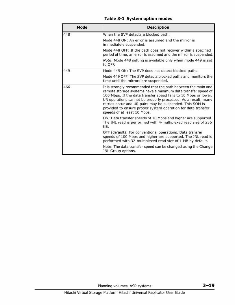
Planning volumes, VSP systems 3–19Hitachi Virtual Storage Platform Hitachi Universal Replicator User Guide
Table 3-1 System option modes
Mode Description
448 When the SVP detects a blocked path:Mode 448 ON: An error is assumed and the mirror is immediately suspended.Mode 448 OFF: If the path does not recover within a specified period of time, an error is assumed and the mirror is suspended.Note: Mode 448 setting is available only when mode 449 is set to OFF.
449 Mode 449 ON: The SVP does not detect blocked paths. Mode 449 OFF: The SVP detects blocked paths and monitors the time until the mirrors are suspended.
466 It is strongly recommended that the path between the main and remote storage systems have a minimum data transfer speed of 100 Mbps. If the data transfer speed falls to 10 Mbps or lower, UR operations cannot be properly processed. As a result, many retries occur and UR pairs may be suspended. This SOM is provided to ensure proper system operation for data transfer speeds of at least 10 Mbps.ON: Data transfer speeds of 10 Mbps and higher are supported. The JNL read is performed with 4-multiplexed read size of 256 KB.OFF (default): For conventional operations. Data transfer speeds of 100 Mbps and higher are supported. The JNL read is performed with 32-multiplexed read size of 1 MB by default.Note: The data transfer speed can be changed using the Change JNL Group options.
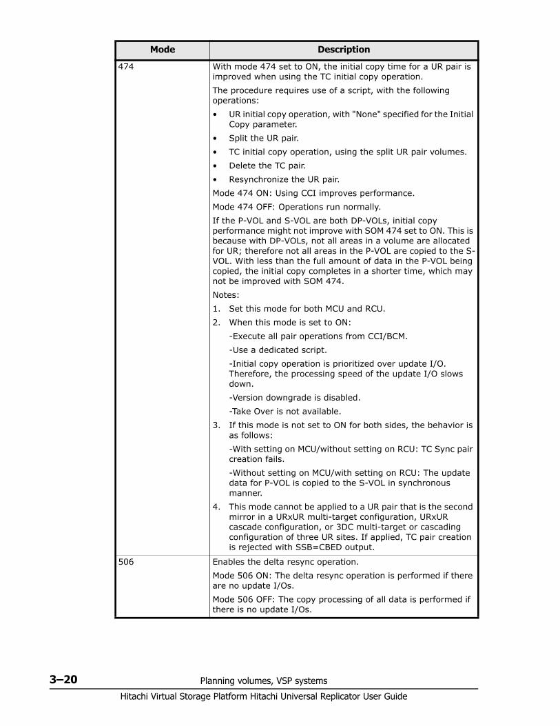
Hitachi Virtual Storage Platform Hitachi Universal Replicator User Guide
3–20 Planning volumes, VSP systems
474 With mode 474 set to ON, the initial copy time for a UR pair is improved when using the TC initial copy operation.The procedure requires use of a script, with the following operations:• UR initial copy operation, with "None" specified for the Initial
Copy parameter.• Split the UR pair.• TC initial copy operation, using the split UR pair volumes.• Delete the TC pair.• Resynchronize the UR pair.Mode 474 ON: Using CCI improves performance. Mode 474 OFF: Operations run normally.If the P-VOL and S-VOL are both DP-VOLs, initial copy performance might not improve with SOM 474 set to ON. This is because with DP-VOLs, not all areas in a volume are allocated for UR; therefore not all areas in the P-VOL are copied to the S-VOL. With less than the full amount of data in the P-VOL being copied, the initial copy completes in a shorter time, which may not be improved with SOM 474.Notes:1. Set this mode for both MCU and RCU.2. When this mode is set to ON:
-Execute all pair operations from CCI/BCM.-Use a dedicated script.-Initial copy operation is prioritized over update I/O. Therefore, the processing speed of the update I/O slows down.-Version downgrade is disabled.-Take Over is not available.
3. If this mode is not set to ON for both sides, the behavior is as follows:-With setting on MCU/without setting on RCU: TC Sync pair creation fails.-Without setting on MCU/with setting on RCU: The update data for P-VOL is copied to the S-VOL in synchronous manner.
4. This mode cannot be applied to a UR pair that is the second mirror in a URxUR multi-target configuration, URxUR cascade configuration, or 3DC multi-target or cascading configuration of three UR sites. If applied, TC pair creation is rejected with SSB=CBED output.
506 Enables the delta resync operation. Mode 506 ON: The delta resync operation is performed if there are no update I/Os.Mode 506 OFF: The copy processing of all data is performed if there is no update I/Os.
Mode Description
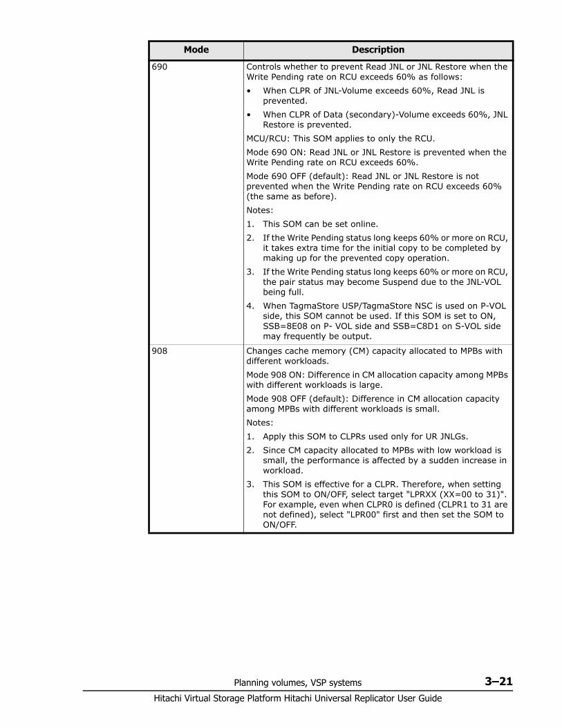
Planning volumes, VSP systems 3–21Hitachi Virtual Storage Platform Hitachi Universal Replicator User Guide
690 Controls whether to prevent Read JNL or JNL Restore when the Write Pending rate on RCU exceeds 60% as follows:• When CLPR of JNL-Volume exceeds 60%, Read JNL is
prevented.• When CLPR of Data (secondary)-Volume exceeds 60%, JNL
Restore is prevented.MCU/RCU: This SOM applies to only the RCU.Mode 690 ON: Read JNL or JNL Restore is prevented when the Write Pending rate on RCU exceeds 60%.Mode 690 OFF (default): Read JNL or JNL Restore is not prevented when the Write Pending rate on RCU exceeds 60% (the same as before).Notes:1. This SOM can be set online.2. If the Write Pending status long keeps 60% or more on RCU,
it takes extra time for the initial copy to be completed by making up for the prevented copy operation.
3. If the Write Pending status long keeps 60% or more on RCU, the pair status may become Suspend due to the JNL-VOL being full.
4. When TagmaStore USP/TagmaStore NSC is used on P-VOL side, this SOM cannot be used. If this SOM is set to ON, SSB=8E08 on P- VOL side and SSB=C8D1 on S-VOL side may frequently be output.
908 Changes cache memory (CM) capacity allocated to MPBs with different workloads.Mode 908 ON: Difference in CM allocation capacity among MPBs with different workloads is large.Mode 908 OFF (default): Difference in CM allocation capacity among MPBs with different workloads is small.Notes:1. Apply this SOM to CLPRs used only for UR JNLGs.2. Since CM capacity allocated to MPBs with low workload is
small, the performance is affected by a sudden increase in workload.
3. This SOM is effective for a CLPR. Therefore, when setting this SOM to ON/OFF, select target "LPRXX (XX=00 to 31)". For example, even when CLPR0 is defined (CLPR1 to 31 are not defined), select "LPR00" first and then set the SOM to ON/OFF.
Mode Description

Hitachi Virtual Storage Platform Hitachi Universal Replicator User Guide
3–22 Planning volumes, VSP systems
4
Planning the data path 4–1Hitachi Virtual Storage Platform Hitachi Universal Replicator User Guide
Planning the data path
A data path must be designed to manage your organization’s throughput to the remote site. The bandwidth, number of ports, and fibre-channel data path configuration that you use help ensure that your update data arrives at the remote site in a time consistent with your organization’s RPO.
This chapter provides instructions for calculating bandwidth and designing the data path network.
□ Data path design workflow
□ Sizing bandwidth
□ Planning ports for data transfer
□ Cable length and switch requirements
□ Supported data path configurations
Hitachi Virtual Storage Platform Hitachi Universal Replicator User Guide
4–2 Planning the data path
Data path design workflow To set up a data path, you must establish the following:• The amount of bandwidth to move data generated by your host
application under all I/O conditions. See Sizing bandwidth on page 4-2.• Ports that can send and receive data. See Planning ports for data
transfer on page 4-7.• The type of cable and number of switches required. See Cable length
and switch requirements on page 4-8.• The configuration that works best for your sites. See Supported data
path configurations on page 4-10.
This chapter discusses these topics in detail.
Sizing bandwidth You purchase bandwidth according to the amount of data that will be transferred from the primary to the secondary system within a certain amount of time.
If the data path network cannot keep pace with the flow of data, the data is saved in the journal until additional bandwidth capacity becomes available. If the journal also cannot keep up, the integrity of the pairs is lost and a new initial copy must be created.
In general, bandwidth is expensive. Adding capacity to a journal volume is relatively inexpensive. But the more data that accumulates in the journal, the further the secondary image is from the production volumes. Therefore, sizing bandwidth is a trade-off between expense and keeping your secondary volume as consistent as you need it to be with the primary volume.
Five sizing strategies The following sizing strategies are provided to help you work out an approach to sizing bandwidth. Be aware that these are not the only strategies you can use.• Size bandwidth to peak workload. This results in the smallest
difference between data in the P-VOL and S-VOL. Identify peak workload on the production disks, then add extra capacity to accommodate packet loss and protocol overhead. RPO is at or near zero when bandwidth is sized to peak workload.
• Size bandwidth to peak workload rolling average. The rolling average is less than peak but more than average. This guarantees that at some point data will accumulate in the journal, but most of the time it will not. Your system can afford to journal for the amount of time planned for and still maintain RPO.
• Size bandwidth to typical workload. When bandwidth is sized to typical write-workload, and an extended peak workload is experienced, excess write-data is written to journal. This excess data is delayed for
Planning the data path 4–3Hitachi Virtual Storage Platform Hitachi Universal Replicator User Guide
subsequent FIFO transmission to the remote site when network capacity becomes available. Differential data is proportional to the amplitude and duration of the workload surge.
• If you cannot determine a “typical” workload, sizing should be to the average or mean workload, plus a small compensation for network overhead. In this scenario, excess data in the journals will be completely emptied to the S-VOL only occasionally. If bandwidth is sized below average write-workload, the journals never fully drain and eventually overflow.
• You can size bandwidth and journal size for long-haul data migration, to be used where data consistency is not required. In this strategy, you alternate pair status between resync and suspend in order to “batch copy” point-in-time copies. When pairs are suspended, journals are not used to queue write operations. Rather, a bitmap is used to track which cylinders have changed on the physical disks. For access patterns that favor multiple writes to a relatively small region of disk, this technique can provide especially efficient transfer of data, since multiple writes to one region are not sent each and every time. Only the last update before resync is sent. The disadvantage of this strategy is that it does not guarantee I/O consistency on the secondary system until the resync completes.
Calculating bandwidth To determine bandwidth for Universal Replicator, write-workload must be measured. Production system workload data is collected using performance monitoring software. Please see Measuring write-workload on page 3-4.
When you have collected write-workload data, size your bandwidth according to your sizing strategy. In the following procedures, bandwidth is sized for peak and peak rolling average write-workload.
Sizing bandwidth for peak write-workload1. Make sure that write-workload data is imported into a spreadsheet tool.
Column C in the figure below shows an example of collected raw data over 10-minute segments.
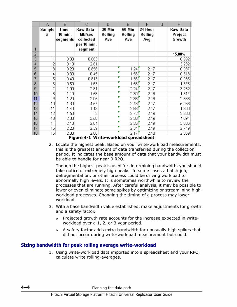
Hitachi Virtual Storage Platform Hitachi Universal Replicator User Guide
4–4 Planning the data path
2. Locate the highest peak. Based on your write-workload measurements, this is the greatest amount of data transferred during the collection period. It indicates the base amount of data that your bandwidth must be able to handle for near 0 RPO.Though the highest peak is used for determining bandwidth, you should take notice of extremely high peaks. In some cases a batch job, defragmentation, or other process could be driving workload to abnormally high levels. It is sometimes worthwhile to review the processes that are running. After careful analysis, it may be possible to lower or even eliminate some spikes by optimizing or streamlining high-workload processes. Changing the timing of a process may lower workload.
3. With a base bandwidth value established, make adjustments for growth and a safety factor. Projected growth rate accounts for the increase expected in write-
workload over a 1, 2, or 3 year period. A safety factor adds extra bandwidth for unusually high spikes that
did not occur during write-workload measurement but could.
Sizing bandwidth for peak rolling average write-workload1. Using write-workload data imported into a spreadsheet and your RPO,
calculate write rolling-averages.
Figure 4-1 Write-workload spreadsheet
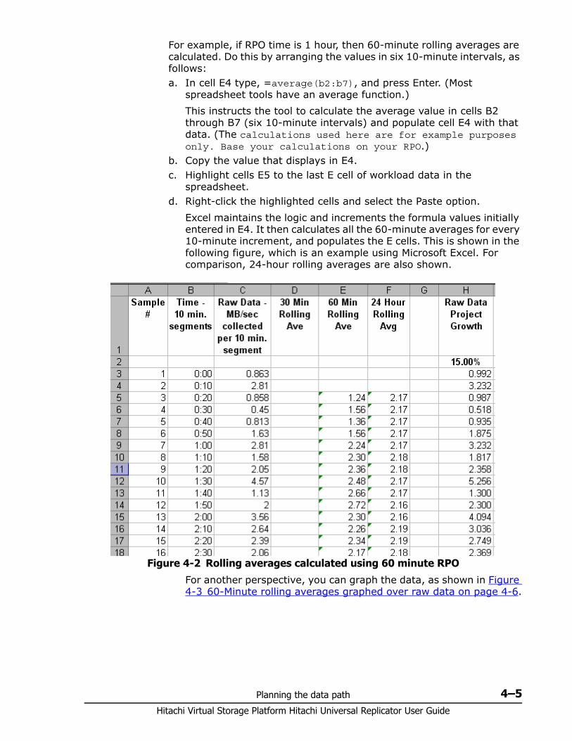
Planning the data path 4–5Hitachi Virtual Storage Platform Hitachi Universal Replicator User Guide
For example, if RPO time is 1 hour, then 60-minute rolling averages are calculated. Do this by arranging the values in six 10-minute intervals, as follows:a. In cell E4 type, =average(b2:b7), and press Enter. (Most
spreadsheet tools have an average function.)This instructs the tool to calculate the average value in cells B2 through B7 (six 10-minute intervals) and populate cell E4 with that data. (The calculations used here are for example purposes only. Base your calculations on your RPO.)
b. Copy the value that displays in E4.c. Highlight cells E5 to the last E cell of workload data in the
spreadsheet.d. Right-click the highlighted cells and select the Paste option.
Excel maintains the logic and increments the formula values initially entered in E4. It then calculates all the 60-minute averages for every 10-minute increment, and populates the E cells. This is shown in the following figure, which is an example using Microsoft Excel. For comparison, 24-hour rolling averages are also shown.
For another perspective, you can graph the data, as shown in Figure 4-3 60-Minute rolling averages graphed over raw data on page 4-6.
Figure 4-2 Rolling averages calculated using 60 minute RPO
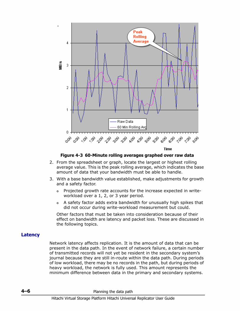
Hitachi Virtual Storage Platform Hitachi Universal Replicator User Guide
4–6 Planning the data path
2. From the spreadsheet or graph, locate the largest or highest rolling average value. This is the peak rolling average, which indicates the base amount of data that your bandwidth must be able to handle.
3. With a base bandwidth value established, make adjustments for growth and a safety factor. Projected growth rate accounts for the increase expected in write-
workload over a 1, 2, or 3 year period. A safety factor adds extra bandwidth for unusually high spikes that
did not occur during write-workload measurement but could.Other factors that must be taken into consideration because of their effect on bandwidth are latency and packet loss. These are discussed in the following topics.
Latency
Network latency affects replication. It is the amount of data that can be present in the data path. In the event of network failure, a certain number of transmitted records will not yet be resident in the secondary system’s journal because they are still in-route within the data path. During periods of low workload, there may be no records in the path, but during periods of heavy workload, the network is fully used. This amount represents the minimum difference between data in the primary and secondary systems.
Figure 4-3 60-Minute rolling averages graphed over raw data
Planning the data path 4–7Hitachi Virtual Storage Platform Hitachi Universal Replicator User Guide
Packet loss
Packet losses have the effect of reducing overall bandwidth because lost packets must be re-transmitted, which consumes network capacity that would otherwise be occupied by new data traffic. Also, a network can elongate consistency time, since journals are not applied until a contiguous sequence of records has arrived at the secondary site.
Planning ports for data transfer When new data exists in the P-VOL, informational commands are sent from the primary system initiator port to the secondary system RCU target port.
The secondary system initiator port sends journal query commands to the primary RCU target port. The data is then sent through these ports — that is, from primary side RCU target ports to secondary system initiator ports.
Note the following:• An initiator port on one side must have an RCU target port on the other
side. • Two or more initiator ports must be configured before you can create the
UR relationship with the secondary system and create pairs.• The amount of data each of port can transmit is limited. Therefore, it is
critical to know the amount of data that will be transferred during peak periods. This knowledge will ensure that you can set up a sufficient number of ports as initiator and RCU target ports in order to handle all workloads.
• If your UR system supports a disaster recovery failover/failback environment, initiator and RCU target ports should be sized equivalently on primary and secondary systems.
• Up to eight paths can be established in both directions. It is recommended that you establish at least two independent data paths to provide hardware redundancy.
• Host paths cannot be connected to an initiator port. However, they can be attached to RCU target ports.
Example configuration• Two initiator ports on the local side, with two matching RCU target ports
on the remote side• Four initiator ports on the remote side, with four matching RCU target
ports on the local side.
Port typesThe primary and secondary systems require both initiator and RCU target ports. Both systems send and receive traffic during active replication. • The initiator port on the primary side is connected to the RCU target port
on the secondary side.
Hitachi Virtual Storage Platform Hitachi Universal Replicator User Guide
4–8 Planning the data path
• The initiator port on the secondary side is connected to the RCU target port on the primary side.
VSP ports are designated as target ports by default. When you determine the number of initiator ports and RCU target ports your UR system requires, you change port attributes from target to initiator and RCU target.
The fibre-channel ports on VSP systems can have the following attributes:• Initiator port: Sends UR commands to the paired system. Initiator
ports must be configured on both primary and secondary systems for pair operations.Two or more initiator ports must be configured before you can add the secondary systems and create pairs.
• RCU Target port: Receives UR commands and data. RCU target ports must be configured on both primary and remote storage systems for pair operations.
• Target port: Connects the system and an open systems host. When the host issues a write request, the request is sent via a target port to a volume on the VSP system. Target ports must be configured on primary systems for UR operations.
• External port: Required for Universal Volume Manager copy operations. This port is not used for UR copy operations. This port can be changed to a target, initiator, or RCU target port.
Determining required number of ports The data transfer speed of your UR ports must be greater than peak write-IOPS. This means that you must dedicate the number of ports to a UR pair that will be able to handle the peak IOPS generated by your production system. The minimum number of ports for a UR system is two.
To determine the required number of initiator and RCU target ports1. Measure the write workload you want to replicate on your production
system. When you measure write-workload, IOPS is also provided. (See Measuring write-workload on page 3-4 for more information.)
2. Using peak IOPS and the maximum IOPS for a VSP fibre-channel port (70,000), calculate the number of ports your UR system requires.Peak IOPS / 70,000
For example: if your performance monitoring software shows peak IOPS at 280,000, then the calculation would be:280,000 / 70,000 (max. IOPS per port) = 4. This example shows that four ports are required for the measured peak IOPS.
Cable length and switch requirementsMultimode or single-mode optical fiber cables are required on primary and secondary systems. The type of cable and number of switches depends on the distance between primary and secondary sites.
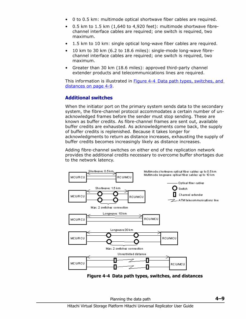
Planning the data path 4–9Hitachi Virtual Storage Platform Hitachi Universal Replicator User Guide
• 0 to 0.5 km: multimode optical shortwave fiber cables are required.• 0.5 km to 1.5 km (1,640 to 4,920 feet): multimode shortwave fibre-
channel interface cables are required; one switch is required, two maximum.
• 1.5 km to 10 km: single optical long-wave fiber cables are required.• 10 km to 30 km (6.2 to 18.6 miles): single-mode long-wave fibre-
channel interface cables are required; one switch is required, two maximum.
• Greater than 30 km (18.6 miles): approved third-party channel extender products and telecommunications lines are required.
This information is illustrated in Figure 4-4 Data path types, switches, and distances on page 4-9.
Additional switches
When the initiator port on the primary system sends data to the secondary system, the fibre-channel protocol accommodates a certain number of un-acknowledged frames before the sender must stop sending. These are known as buffer credits. As fibre-channel frames are sent out, available buffer credits are exhausted. As acknowledgments come back, the supply of buffer credits is replenished. Because it takes longer for acknowledgments to return as distance increases, exhausting the supply of buffer credits becomes increasingly likely as distance increases.
Adding fibre-channel switches on either end of the replication network provides the additional credits necessary to overcome buffer shortages due to the network latency.
Figure 4-4 Data path types, switches, and distances
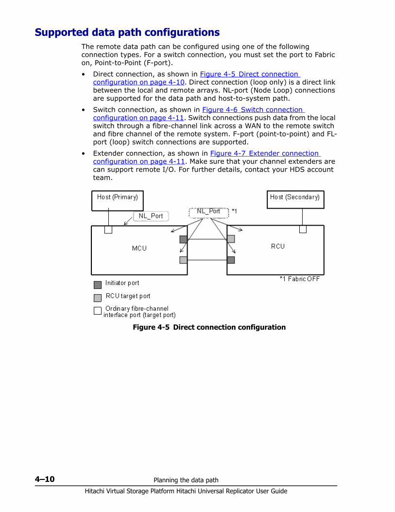
Hitachi Virtual Storage Platform Hitachi Universal Replicator User Guide
4–10 Planning the data path
Supported data path configurations The remote data path can be configured using one of the following connection types. For a switch connection, you must set the port to Fabric on, Point-to-Point (F-port).• Direct connection, as shown in Figure 4-5 Direct connection
configuration on page 4-10. Direct connection (loop only) is a direct link between the local and remote arrays. NL-port (Node Loop) connections are supported for the data path and host-to-system path.
• Switch connection, as shown in Figure 4-6 Switch connection configuration on page 4-11. Switch connections push data from the local switch through a fibre-channel link across a WAN to the remote switch and fibre channel of the remote system. F-port (point-to-point) and FL-port (loop) switch connections are supported.
• Extender connection, as shown in Figure 4-7 Extender connection configuration on page 4-11. Make sure that your channel extenders are can support remote I/O. For further details, contact your HDS account team.
Figure 4-5 Direct connection configuration
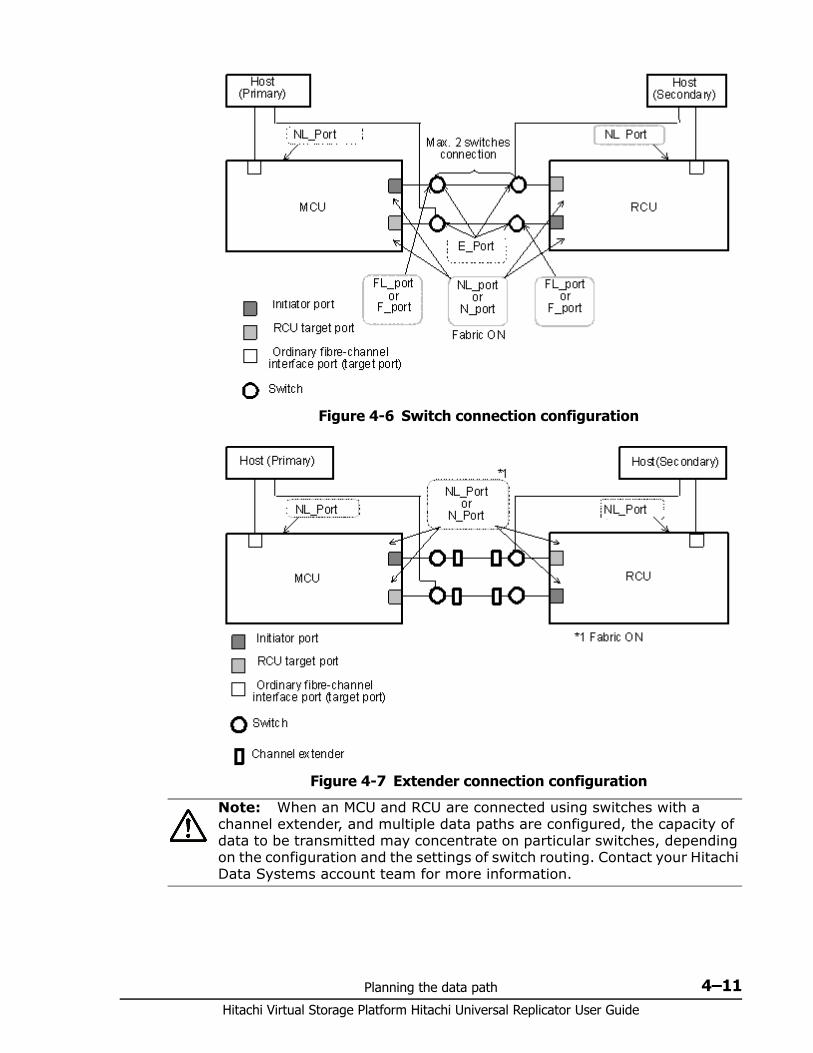
Planning the data path 4–11Hitachi Virtual Storage Platform Hitachi Universal Replicator User Guide
Figure 4-6 Switch connection configuration
Figure 4-7 Extender connection configuration
Note: When an MCU and RCU are connected using switches with a channel extender, and multiple data paths are configured, the capacity of data to be transmitted may concentrate on particular switches, depending on the configuration and the settings of switch routing. Contact your Hitachi Data Systems account team for more information.

Hitachi Virtual Storage Platform Hitachi Universal Replicator User Guide
4–12 Planning the data path
5
Configuration operations 5–1Hitachi Virtual Storage Platform Hitachi Universal Replicator User Guide
Configuration operations
This chapter provides instructions for configuring Universal Replicator.
□ Configuration workflow
□ Defining fibre-channel port attributes
□ Configuring local and remote systems for UR
□ Configuring additional logical paths
□ Specifying number of concurrent initial/resync copies
□ Registering journal volumes in a journal
Hitachi Virtual Storage Platform Hitachi Universal Replicator User Guide
5–2 Configuration operations
Configuration workflow This workflow and subsequent topics guides you in setting up the primary and secondary systems for Universal Replicator operations using Storage Navigator. 1. Log in to Storage Navigator. 2. Define the fibre-channel port attributes. See Defining fibre-channel port
attributes on page 5-2, below.3. Set up logical paths between the primary and secondary systems. See
Configuring local and remote systems for UR on page 5-34. Register journal volumes in a journal. See Registering journal volumes
in a journal on page 5-10
You may also perform these additional procedures before the initial copy:• Add more logical paths. See Configuring additional logical paths on page
5-7.• Specify the number of volumes to copy. See Specifying number of
concurrent initial/resync copies on page 5-8.
Be sure to check the prerequisites for each procedure. Some tasks are performed from both local and remote systems. Other tasks are performed from one or the other.
Defining fibre-channel port attributes Initiator, and RCU target ports must be set up on the primary and secondary systems for Universal Replicator command and data transfer.
Prerequisite information• Before a fiber channel target port can be changed to an initiator port,
the following must be performed: Disconnect the port from the host. Release all affected pairs. Delete all logical paths from the initiator port to the remote system. Remove all cables to the port.
• Before a fiber channel initiator port can be changed to target or RCU target, the following must be performed: Release all affected pair. Delete all logical paths from the initiator port to the remote system. After logical paths are deleted, remove the cables connecting the
local system to the remote system.• Check that the number of hosts connected to a target port is not more
that the maximum of 128 to avoid disconnection.
See Planning ports for data transfer on page 4-7 for information on target, initiator, and RCU target ports and to determine the number of initiator and RCU target ports required by your system.
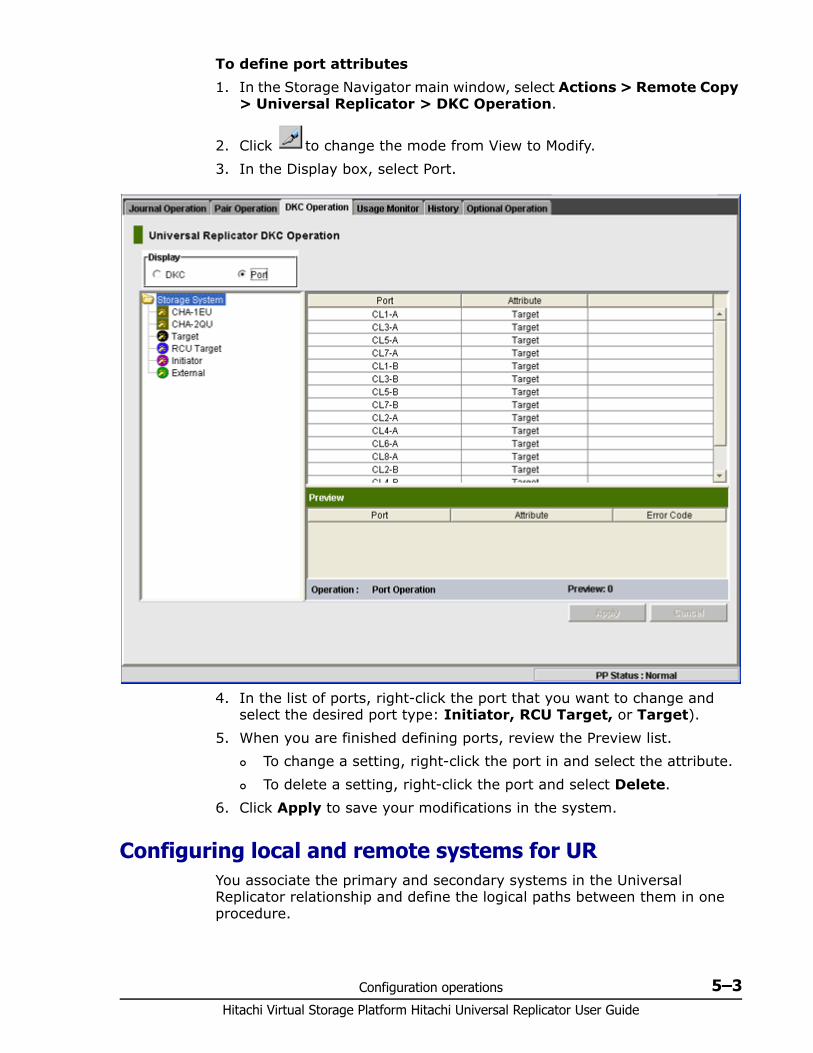
Configuration operations 5–3Hitachi Virtual Storage Platform Hitachi Universal Replicator User Guide
To define port attributes1. In the Storage Navigator main window, select Actions > Remote Copy
> Universal Replicator > DKC Operation.
2. Click to change the mode from View to Modify.3. In the Display box, select Port.
4. In the list of ports, right-click the port that you want to change and select the desired port type: Initiator, RCU Target, or Target).
5. When you are finished defining ports, review the Preview list. To change a setting, right-click the port in and select the attribute. To delete a setting, right-click the port and select Delete.
6. Click Apply to save your modifications in the system.
Configuring local and remote systems for UR You associate the primary and secondary systems in the Universal Replicator relationship and define the logical paths between them in one procedure.
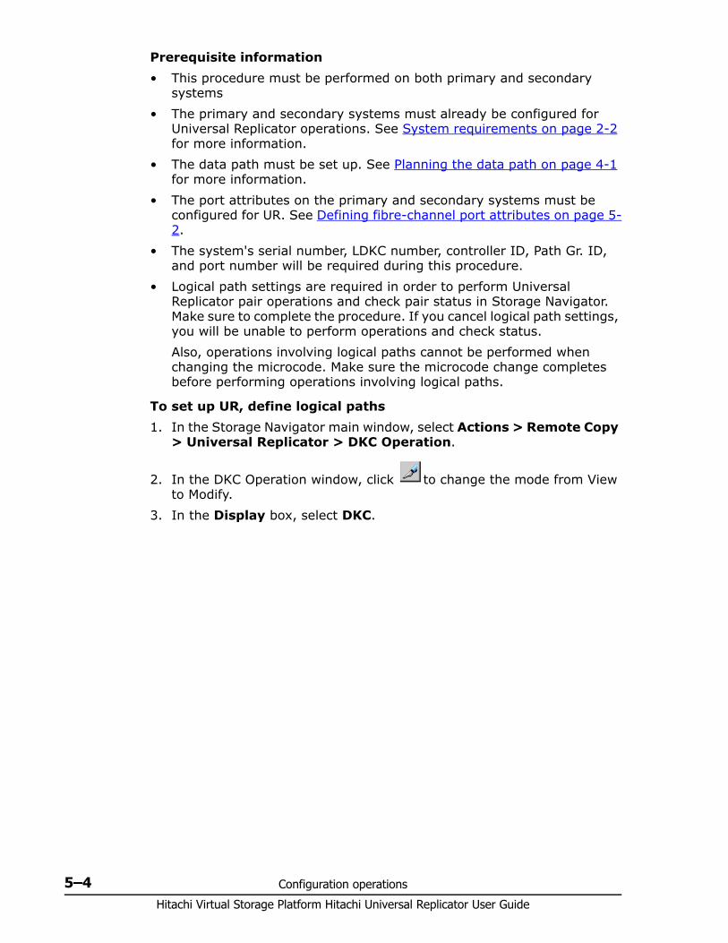
Hitachi Virtual Storage Platform Hitachi Universal Replicator User Guide
5–4 Configuration operations
Prerequisite information• This procedure must be performed on both primary and secondary
systems• The primary and secondary systems must already be configured for
Universal Replicator operations. See System requirements on page 2-2 for more information.
• The data path must be set up. See Planning the data path on page 4-1 for more information.
• The port attributes on the primary and secondary systems must be configured for UR. See Defining fibre-channel port attributes on page 5-2.
• The system's serial number, LDKC number, controller ID, Path Gr. ID, and port number will be required during this procedure.
• Logical path settings are required in order to perform Universal Replicator pair operations and check pair status in Storage Navigator. Make sure to complete the procedure. If you cancel logical path settings, you will be unable to perform operations and check status.Also, operations involving logical paths cannot be performed when changing the microcode. Make sure the microcode change completes before performing operations involving logical paths.
To set up UR, define logical paths1. In the Storage Navigator main window, select Actions > Remote Copy
> Universal Replicator > DKC Operation.
2. In the DKC Operation window, click to change the mode from View to Modify.
3. In the Display box, select DKC.
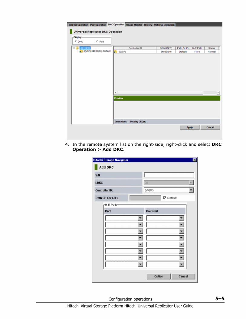
Configuration operations 5–5Hitachi Virtual Storage Platform Hitachi Universal Replicator User Guide
4. In the remote system list on the right-side, right-click and select DKC Operation > Add DKC.
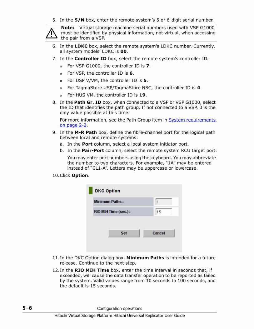
Hitachi Virtual Storage Platform Hitachi Universal Replicator User Guide
5–6 Configuration operations
5. In the S/N box, enter the remote system’s 5 or 6-digit serial number.
6. In the LDKC box, select the remote system’s LDKC number. Currently, all system models’ LDKC is 00.
7. In the Controller ID box, select the remote system’s controller ID. For VSP G1000, the controller ID is 7. For VSP, the controller ID is 6. For USP V/VM, the controller ID is 5. For TagmaStore USP/TagmaStore NSC, the controller ID is 4. For HUS VM, the controller ID is 19.
8. In the Path Gr. ID box, when connected to a VSP or VSP G1000, select the ID that identifies the path group. If not connected to a VSP, 0 is the only value possible at this time.For more information, see the Path Group item in System requirements on page 2-2.
9. In the M-R Path box, define the fibre-channel port for the logical path between local and remote systems:a. In the Port column, select a local system initiator port.b. In the Pair-Port column, select the remote system RCU target port.
You may enter port numbers using the keyboard. You may abbreviate the number to two characters. For example, “1A” may be entered instead of “CL1-A”. Letters may be uppercase or lowercase.
10.Click Option.
11.In the DKC Option dialog box, Minimum Paths is intended for a future release. Continue to the next step.
12.In the RIO MIH Time box, enter the time interval in seconds that, if exceeded, will cause the data transfer operation to be reported as failed by the system. Valid values range from 10 seconds to 100 seconds, and the default is 15 seconds.
Note: Virtual storage machine serial numbers used with VSP G1000 must be identified by physical information, not virtual, when accessing the pair from a VSP.
Configuration operations 5–7Hitachi Virtual Storage Platform Hitachi Universal Replicator User Guide
RIO MIH means “remote I/O missing interrupt handler”.
13.Click Set. To change a path, right-click it in the Preview list and select Modify.
Make any changes in the Add Path dialog box then click Set. To delete an added logical path, right-click the path in the Preview
list and select Delete.14.Click Apply to save the configuration.
Configuring additional logical paths You can configure additional logical paths as needed. A maximum of eight logical paths are supported.
Prerequisite information
Review the prerequisites for configuring logical paths in Configuring local and remote systems for UR on page 5-3.
To configure additional logical paths1. In the Storage Navigator main window, select Actions > Remote Copy
> Universal Replicator > DKC Operation.
2. Click to change the mode from View to Modify.3. In the tree, select the remote system. The logical paths display in the
full right-side list.4. Right-click a logical path, and select Add Path from the menu.
Note: The recommended RIO MIH setting for a 3DC cascade configuration is 20 seconds.
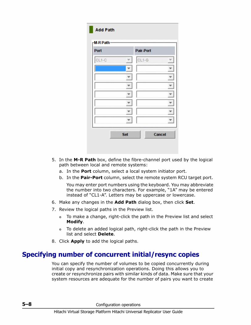
Hitachi Virtual Storage Platform Hitachi Universal Replicator User Guide
5–8 Configuration operations
5. In the M-R Path box, define the fibre-channel port used by the logical path between local and remote systems:a. In the Port column, select a local system initiator port.b. In the Pair-Port column, select the remote system RCU target port.
You may enter port numbers using the keyboard. You may abbreviate the number into two characters. For example, “1A” may be entered instead of “CL1-A”. Letters may be uppercase or lowercase.
6. Make any changes in the Add Path dialog box, then click Set.7. Review the logical paths in the Preview list.
To make a change, right-click the path in the Preview list and select Modify.
To delete an added logical path, right-click the path in the Preview list and select Delete.
8. Click Apply to add the logical paths.
Specifying number of concurrent initial/resync copiesYou can specify the number of volumes to be copied concurrently during initial copy and resynchronization operations. Doing this allows you to create or resynchronize pairs with similar kinds of data. Make sure that your system resources are adequate for the number of pairs you want to create
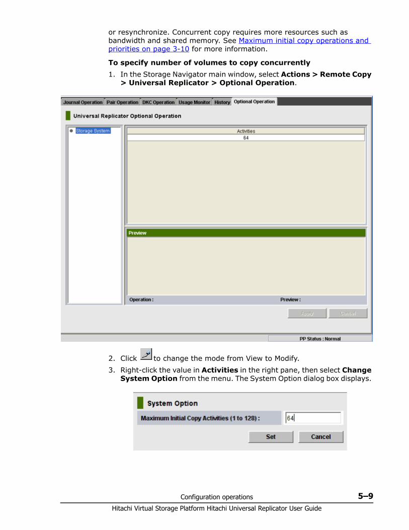
Configuration operations 5–9Hitachi Virtual Storage Platform Hitachi Universal Replicator User Guide
or resynchronize. Concurrent copy requires more resources such as bandwidth and shared memory. See Maximum initial copy operations and priorities on page 3-10 for more information.
To specify number of volumes to copy concurrently1. In the Storage Navigator main window, select Actions > Remote Copy
> Universal Replicator > Optional Operation.
2. Click to change the mode from View to Modify.3. Right-click the value in Activities in the right pane, then select Change
System Option from the menu. The System Option dialog box displays.
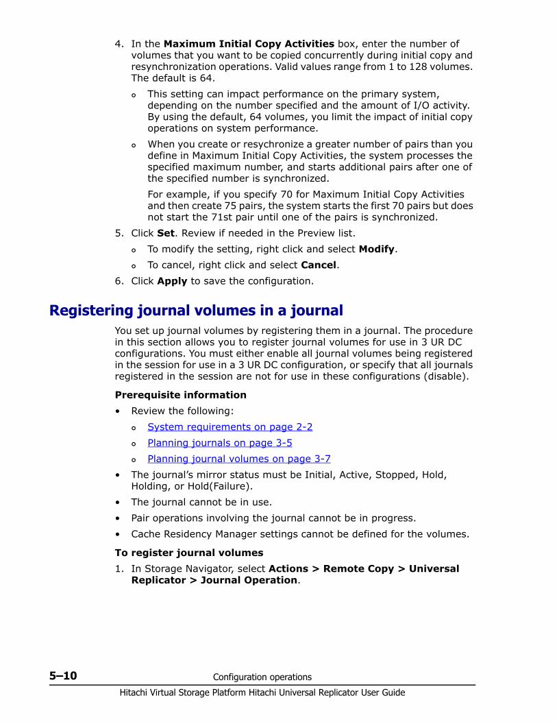
Hitachi Virtual Storage Platform Hitachi Universal Replicator User Guide
5–10 Configuration operations
4. In the Maximum Initial Copy Activities box, enter the number of volumes that you want to be copied concurrently during initial copy and resynchronization operations. Valid values range from 1 to 128 volumes. The default is 64. This setting can impact performance on the primary system,
depending on the number specified and the amount of I/O activity. By using the default, 64 volumes, you limit the impact of initial copy operations on system performance.
When you create or resychronize a greater number of pairs than you define in Maximum Initial Copy Activities, the system processes the specified maximum number, and starts additional pairs after one of the specified number is synchronized.For example, if you specify 70 for Maximum Initial Copy Activities and then create 75 pairs, the system starts the first 70 pairs but does not start the 71st pair until one of the pairs is synchronized.
5. Click Set. Review if needed in the Preview list. To modify the setting, right click and select Modify. To cancel, right click and select Cancel.
6. Click Apply to save the configuration.
Registering journal volumes in a journal You set up journal volumes by registering them in a journal. The procedure in this section allows you to register journal volumes for use in 3 UR DC configurations. You must either enable all journal volumes being registered in the session for use in a 3 UR DC configuration, or specify that all journals registered in the session are not for use in these configurations (disable).
Prerequisite information• Review the following:
System requirements on page 2-2 Planning journals on page 3-5 Planning journal volumes on page 3-7
• The journal’s mirror status must be Initial, Active, Stopped, Hold, Holding, or Hold(Failure).
• The journal cannot be in use.• Pair operations involving the journal cannot be in progress.• Cache Residency Manager settings cannot be defined for the volumes.
To register journal volumes1. In Storage Navigator, select Actions > Remote Copy > Universal
Replicator > Journal Operation.
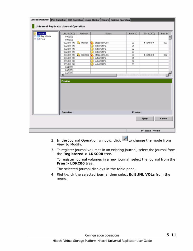
Configuration operations 5–11Hitachi Virtual Storage Platform Hitachi Universal Replicator User Guide
2. In the Journal Operation window, click to change the mode from View to Modify.
3. To register journal volumes in an existing journal, select the journal from the Registered > LDKC00 tree. To register journal volumes in a new journal, select the journal from the Free > LDKC00 tree.The selected journal displays in the table pane.
4. Right-click the selected journal then select Edit JNL VOLs from the menu.
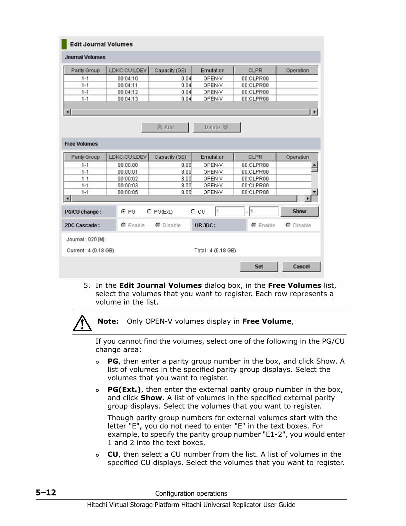
Hitachi Virtual Storage Platform Hitachi Universal Replicator User Guide
5–12 Configuration operations
5. In the Edit Journal Volumes dialog box, in the Free Volumes list, select the volumes that you want to register. Each row represents a volume in the list.
If you cannot find the volumes, select one of the following in the PG/CU change area: PG, then enter a parity group number in the box, and click Show. A
list of volumes in the specified parity group displays. Select the volumes that you want to register.
PG(Ext.), then enter the external parity group number in the box, and click Show. A list of volumes in the specified external parity group displays. Select the volumes that you want to register.Though parity group numbers for external volumes start with the letter "E", you do not need to enter "E" in the text boxes. For example, to specify the parity group number "E1-2", you would enter 1 and 2 into the text boxes.
CU, then select a CU number from the list. A list of volumes in the specified CU displays. Select the volumes that you want to register.
Note: Only OPEN-V volumes display in Free Volume,
Configuration operations 5–13Hitachi Virtual Storage Platform Hitachi Universal Replicator User Guide
6. Use UR 2DC or 3DC to assign journals for use in 2-UR DC or 3-UR DC configurations. You must enable or disable this option for all journals being registered. Only unused journals can be specified. Select one of the following: Enable: Defines journals for use in 2-UR DC or 3 UR DC
configurations. Note that when a journal is defined for a 3 UR DC configuration, the micro code cannot be downgraded to 70-03-xx or earlier. The journal would have to be deleted to downgrade.
Disable: Specifies that the journals are not for use in a 2-UR DC or 3 UR DC configuration.
7. Click Add, then Set to close the Edit Journal Volumes dialog box.8. Review the added journal volumes in the Preview list.
To add another volume, right-click the desired journal and select Modify. In the dialog, add the volume and click Set.
To cancel a path, right-click it in the Preview list and select Cancel.9. Click Apply to save the configuration.
After journal volumes are registered to the unused journal, the journals are shown below as Registered >LDKC00 in the tree. If an error occurs, right-click the item in the Preview list and select Error Detail.

Hitachi Virtual Storage Platform Hitachi Universal Replicator User Guide
5–14 Configuration operations
6
Pair operations 6–1Hitachi Virtual Storage Platform Hitachi Universal Replicator User Guide
Pair operations
This chapter provides instructions for performing Universal Replicator pair operations.
□ Pair operations workflow
□ Checking pair status
□ Creating the initial copy
□ Splitting pairs
□ Splitting mirrors
□ Creating point-in-time copies
□ Resynchronizing pairs
□ Resynchronizing mirrors
□ Deleting pairs
□ Deleting pairs in a mirror
Hitachi Virtual Storage Platform Hitachi Universal Replicator User Guide
6–2 Pair operations
Pair operations workflowThe basic UR operations consist of the following:• Check pair status. Each UR operation requires the pair to be in a specific
status.• Create the pair, in which the S-VOL becomes a duplicate of the P-VOL.• Split the pair, which separates the P-VOL and S-VOL and allows read/
write access to the S-VOL if desired.• Restore the pair so that the S-VOL again mirrors the on-going, current
data in the P-VOL.• Delete a pair, which removes the pair relationship from the volumes.
Checking pair statusEvery UR operation requires that pairs have a specific status. Before performing any operation, check pair status.• Find status requirements in the prerequisite information for each
operation. • To view a pair’s current status in the GUI, or to review status definitions,
see Monitoring pair activity and status on page 7-2.
Creating the initial copy The pair is created when you create the initial copy. All data in the P-VOL on the primary system is copied to the S-VOL on the secondary system. The P-VOL remains available to the host for I/O operations.
Prerequisite information • The initial copy must be performed from the primary system.• Pair status of both data volumes must be SMPL.• S-VOLs must be offline to all hosts.• The primary and secondary systems and logical paths must be defined.
See Configuring local and remote systems for UR on page 5-3 for more information.
• Journal volumes must be registered to the journals that are associated with pairs. See Registering journal volumes in a journal on page 5-10 for more information.
Note: Pair operations cannot be performed if micro exchange is in progress or if micro exchange is suspended because the Cancel button has been pressed or because errors have occurred. If you start a microcode change, be sure it completes before performing pair operations.
Note: You cannot use Storage Navigator to perform pair operations or check pair status on volumes with LU path settings that have been canceled. Before you perform pair operations or check the pair status, configure the LU path settings to the volume on which you want to perform these actions.
Pair operations 6–3Hitachi Virtual Storage Platform Hitachi Universal Replicator User Guide
• If you are creating multiple pairs at one time, you must specify the number of volumes that initial copy operations can be performed on concurrently. See Specifying number of concurrent initial/resync copies on page 5-8 for more information.
• If you are creating a UR pair for delta resync, see Procedure for creating a delta resync pair on page C-8.
• Make sure Performance Monitor is stopped.
The following additional information may be useful to you before beginning the procedure:• You will select the volumes you will pair by the volume’s port, GID, and
LUN. Make sure to have this information available.• You will assign master and restore journals to the P-VOL and S-VOL
during the operation. • You will assign a mirror ID to the pair. This identifies the pair within the
journal. A mirror refers to the pair within the journal.
To create an initial copy or copies1. In the Storage Navigator main window, select Actions > Remote Copy
> Universal Replicator > Pair Operation.
2. Click to change the mode from View to Modify.3. In the tree, select the port of the P-VOL or host group (displayed below
the ports).
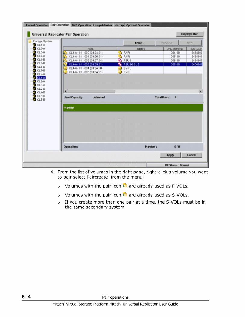
Hitachi Virtual Storage Platform Hitachi Universal Replicator User Guide
6–4 Pair operations
4. From the list of volumes in the right pane, right-click a volume you want to pair select Paircreate from the menu.
Volumes with the pair icon are already used as P-VOLs.
Volumes with the pair icon are already used as S-VOLs. If you create more than one pair at a time, the S-VOLs must be in
the same secondary system.
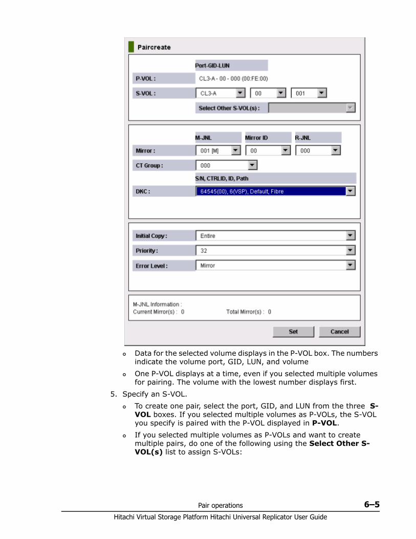
Pair operations 6–5Hitachi Virtual Storage Platform Hitachi Universal Replicator User Guide
Data for the selected volume displays in the P-VOL box. The numbers indicate the volume port, GID, LUN, and volume
One P-VOL displays at a time, even if you selected multiple volumes for pairing. The volume with the lowest number displays first.
5. Specify an S-VOL. To create one pair, select the port, GID, and LUN from the three S-
VOL boxes. If you selected multiple volumes as P-VOLs, the S-VOL you specify is paired with the P-VOL displayed in P-VOL.
If you selected multiple volumes as P-VOLs and want to create multiple pairs, do one of the following using the Select Other S-VOL(s) list to assign S-VOLs:
Hitachi Virtual Storage Platform Hitachi Universal Replicator User Guide
6–6 Pair operations
- Select Increment to add the secondary system LUN incrementally. Your S-VOL LUN numbers must be numbered incrementally. For example, if you create three pairs and specify 011 on the LUN of P-VOL, the LUNs on the secondary system are incremented at 011, 012, and 013.- Select Input Next to specify S-VOL LUNs one at a time for each P-VOL. For example, set the S-VOL LUN for the current P-VOL and click Set, then reopen the dialog box to set the next S-VOL, and so on.- Select Relative to P-VOL to add the S-VOL LUN closest to the P-VOL’s LUN. For example, if the LUN of the three P-VOLs are 001, 005, and 006, and you select LUN 002 for the first S-VOL, LUN numbers 006 and 007 are assigned by the system as the next two S-VOLs.
6. In the Mirror box, proceed as follows. a. Select the master journal from the M-JNL list. b. Select a mirror ID (0 to 3) from the Mirror ID list. c. Select a restore journal from the R-JNL list. Only journal numbers
between 000 and 0FF display.
7. From the CT Group list, specify the consistency group number. If possible, assign the consistency group number matching the Universal Replicator journal number (best practice).
8. In the DKC list, select the secondary system, which must be the same for all pairs created in the operation. Secondary systems are identified in the list by serial number, LDKC number, controller ID, model name, and ID (Path Gr. ID).When the system is not connected to a VSP or VSP G1000, only 0 (default) is available for Path Gr. ID. If a pair is already created in the mirror being used, you must select the same secondary system as the existing pair.
9. In the Initial Copy list, select one of the following: Entire, to create the UR pair relationship and copy the data from
primary to secondary volumes immediately. None, to create the UR pair relationship but copy no data from
primary to secondary volumes. If you select this option, the data in the P-VOL and S-VOL must be identical.
Delta, to create the UR pair for a delta resync. The initial copy operation does not start and the pair status changes to HOLD or HOLDING.
10.In the Priority list, specify the scheduling order for this initial copy operation, if the number of initial copies in the operation is greater than the maximum concurrent copy setting. 1 to 256 can be specified, 32 is the default.See Maximum initial copy operations and priorities on page 3-10 if running more initial copies than previously specified.
Note: The M-JNL list does not display journal numbers used by Universal Replicator for Mainframe.
Pair operations 6–7Hitachi Virtual Storage Platform Hitachi Universal Replicator User Guide
If a time-out error occurs during the Paircreate operation, the copy operation might not have been executed in the order that you set with the Priority parameter. The time out error may be caused by the CU configuration or a remote copy path error. Review the error, release the pair with the error, and then retry the Paircreate operation.
11.In the Error Level list, select one of the following options for the action to take if a failure occurs during this operation: Mirror, to split all pairs in the failed pair’s mirror. Mirror is the
default. LU, to split only the pair that failed.
12.Click Set to close the Paircreate dialog box.13.In the Preview list check your settings.
To modify a setting, right click and select Modify.
To cancel a setting, right click and select Cancel.14.Click Apply to apply the settings and create pairs. 15.In the Pair Operation window, verify that the pair status is correct
based on the initial copy option:
16.(Optional) You can monitor the progress of the paircreate operation by clicking File > Refresh in the menu bar. This updates the information in the list. You can also review current pair activity and pair status in the Detailed Information dialog box. See Monitoring pair activity and status on page 7-2 for more information.
Splitting pairs When you split a pair, write-data is no longer sent to S-VOL and the pair is no longer synchronized. Splitting a pair or mirror gives you a point-in-time copy of the P-VOL.
Prerequisite information • This operation can be performed from the primary or secondary system. • Pair status must be COPY or PAIR.• To split multiple pairs at the same time, the pairs must belong to the
same mirror. This ensures sequence consistency among S-VOLs in the mirror.
Note: If you right click more than one volume in the Preview list and select Modify, the Select Other S-VOL(s) list in the Paircreate dialog box indicates No Change. To change the setting, select another option from the list.
Initial Copy Option Current Pair Status Should Be
Entire or None COPY or PAIR
Delta HOLD, Holding
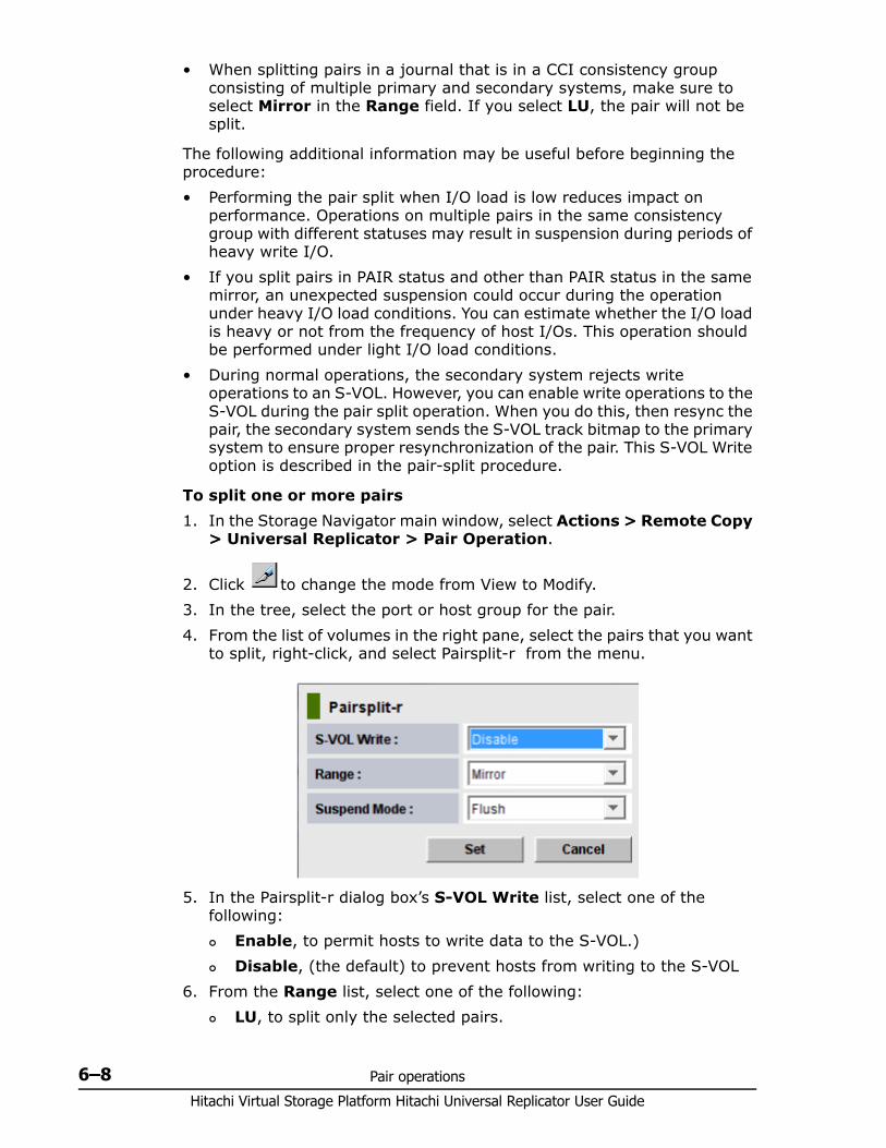
Hitachi Virtual Storage Platform Hitachi Universal Replicator User Guide
6–8 Pair operations
• When splitting pairs in a journal that is in a CCI consistency group consisting of multiple primary and secondary systems, make sure to select Mirror in the Range field. If you select LU, the pair will not be split.
The following additional information may be useful before beginning the procedure:• Performing the pair split when I/O load is low reduces impact on
performance. Operations on multiple pairs in the same consistency group with different statuses may result in suspension during periods of heavy write I/O.
• If you split pairs in PAIR status and other than PAIR status in the same mirror, an unexpected suspension could occur during the operation under heavy I/O load conditions. You can estimate whether the I/O load is heavy or not from the frequency of host I/Os. This operation should be performed under light I/O load conditions.
• During normal operations, the secondary system rejects write operations to an S-VOL. However, you can enable write operations to the S-VOL during the pair split operation. When you do this, then resync the pair, the secondary system sends the S-VOL track bitmap to the primary system to ensure proper resynchronization of the pair. This S-VOL Write option is described in the pair-split procedure.
To split one or more pairs1. In the Storage Navigator main window, select Actions > Remote Copy
> Universal Replicator > Pair Operation.
2. Click to change the mode from View to Modify.3. In the tree, select the port or host group for the pair.4. From the list of volumes in the right pane, select the pairs that you want
to split, right-click, and select Pairsplit-r from the menu.
5. In the Pairsplit-r dialog box’s S-VOL Write list, select one of the following: Enable, to permit hosts to write data to the S-VOL.) Disable, (the default) to prevent hosts from writing to the S-VOL
6. From the Range list, select one of the following: LU, to split only the selected pairs.
Pair operations 6–9Hitachi Virtual Storage Platform Hitachi Universal Replicator User Guide
Mirror, to split all pairs in the selected pairs’s mirror.If you are splitting some pairs in a mirror but not all, you must select LU for each of these pairs. Do not select Mirror in this case, otherwise an error occurs.
7. From the Suspend Mode list, select one of the following: Flush, to copy all update data to the S-VOL before the split operation
is completed.When the secondary system receives a request for splitting a pair, all update data is written to the S-VOL from the journal. The status of the pair changes from Suspending to PSUS.
Purge, to prevent update data from being copied to the S-VOL before the split operation is completed. When you re-synchronize, uncopied update data is then copied to the S-VOL.
8. Click Set.9. Review your settings in the Preview list in the Journal Operation
window. To modify a setting, right click and select Modify. To cancel a setting, right click and select Cancel.
10.Click Apply to commit the settings to the system.
You can verify the PSUS status when the operation is completed.
Splitting mirrors A mirror normally has multiple pairs with the same master and restore journals groups. When you split a mirror, you split all the pairs in the mirror. As with a normal pair split, data copying is suspended between primary and secondary journals.
Prerequisite information• A mirror can be split from the primary or secondary system.• Pair status must be Active.
To split a mirror1. In the Storage Navigator main window, select Actions > Remote Copy
> Universal Replicator > Pair Operation.
2. Click to change the mode from View to Modify.3. In the tree, expand Registered then select the LDKC. Journals display
in the tree and mirrors display in the right pane.4. Select one or more mirrors. 5. Right-click and select Mirror >Pairsplit-r from the menu. 6. In the Pairsplit-r dialog box, follow the steps for the each option in
Splitting pairs on page 6-7. Note that Mirror in the Range field cannot be changed for this operation.
Hitachi Virtual Storage Platform Hitachi Universal Replicator User Guide
6–10 Pair operations
You can verify the Stopped status of the mirror when the mirror split operation is completed.
Creating point-in-time copies Universal Replicator allows you to make Point-in-Time (PiT) copies of volumes in the same journal. Point-in-Time describes a copy of data made when you it.
Prerequisite information
Review the prerequisite information in Splitting pairs on page 6-7.
To make PiT copies of the volumes in a journal1. Stop all write I/Os from hosts to P-VOLs in the journal.2. Split the mirror using the Pairsplit-r dialogue box, specifying Mirror for
Range and Flush for Suspend Mode.3. When the status of all pairs in the journal changed to Suspend, the
operation is completed. You can resume write I/Os to the P-VOLs.
Resynchronizing pairs Resynchronizing a pair updates the S-VOL with differential data that accumulated since the pair was split. After the pair is resynchronized, the S-VOL is again updated via the journals.
Prerequisites for resynchronizing pairs • This operation is performed from the primary system only.• Pair status must be PSUS or PSUE.• The delta resync operation is performed using this procedure. Make sure
to review Prerequisite information for delta resync operation on page C-9, in addition to reviewing the following prerequisites.
The following additional information may be useful before beginning the procedure:• Performing the operation on a pair in HLDE status changes the status to
HOLD.• The primary system does not resynchronize a pair that is suspended due
to an error until the cause of error is resolved.• If P-VOL status is Failure and S-VOL status is SMPL, the pair cannot be
recovered by re-synchronizing. It must be deleted and created again.• Resynchronizing pairs when I/O load is low reduces impact on
performance. Operations on multiple pairs in the same mirror with different statuses may results in suspension during periods of heavy write I/O.
• If you resync pairs in PAIR status and other than PAIR status in the same mirror, an unexpected suspension could occur during the operation under heavy I/O load conditions. You can estimate whether the I/O load is heavy or not from frequency of host I/Os. This operation should be performed under light I/O load conditions.
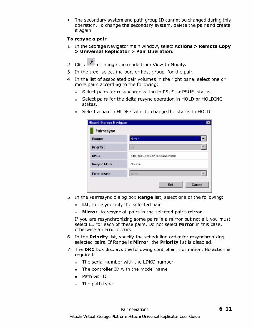
Pair operations 6–11Hitachi Virtual Storage Platform Hitachi Universal Replicator User Guide
• The secondary system and path group ID cannot be changed during this operation. To change the secondary system, delete the pair and create it again.
To resync a pair1. In the Storage Navigator main window, select Actions > Remote Copy
> Universal Replicator > Pair Operation.
2. Click to change the mode from View to Modify.3. In the tree, select the port or host group for the pair. 4. In the list of associated pair volumes in the right pane, select one or
more pairs according to the following: Select pairs for resynchronization in PSUS or PSUE status. Select pairs for the delta resync operation in HOLD or HOLDING
status. Select a pair in HLDE status to change the status to HOLD.
5. In the Pairresync dialog box Range list, select one of the following: LU, to resync only the selected pair. Mirror, to resync all pairs in the selected pair’s mirror.
If you are resynchronizing some pairs in a mirror but not all, you must select LU for each of these pairs. Do not select Mirror in this case, otherwise an error occurs.
6. In the Priority list, specify the scheduling order for resynchronizing selected pairs. If Range is Mirror, the Priority list is disabled.
7. The DKC box displays the following controller information. No action is required. The serial number with the LDKC number The controller ID with the model name Path Gr. ID The path type
Hitachi Virtual Storage Platform Hitachi Universal Replicator User Guide
6–12 Pair operations
8. In the Resync Mode box, select the type of operation you want to perform: Normal. Pair resynchronization operation. Delta. The delta resync operation. Return to standby. Pair status change from HLDE to HOLD.
9. In the Error Level list, select an option for the action that will take place if a failure occurs during this operation. Note that if the Range option is set to Mirror, Error Level options are disabled. Mirror, to split all pairs in the failed pair’s mirror. LU, to split only the specified pair or pairs that failed.
10.Click Set. 11.Review settings in the Preview list in the Journal Operation window.
To modify a setting, right click and select Modify. To cancel a setting, right click and select Cancel.
12.Click Apply to start the operation.
Resynchronizing mirrors When you resynchronize a mirror, all the pairs with the mirror ID are re-synchronized.
Use this procedure also to perform the delta resync operation on all pairs in a mirror or to change pair status of all pairs in the mirror from Hold(Failure) to Hold.
Prerequisite information
This operation must be performed from the primary system only.
The following additional information may be useful to you before beginning the procedure:• Storage Navigator does not support multiple primary and secondary
systems in a UR system. In this case, use CCI to restore a mirror.• Use CCI to restore a mirror that is in a CCI consistency group containing
multiple journals.• Resynchronizing a mirror when I/O load is low reduces impact on
performance.
To resynchronize a mirror1. In the Storage Navigator main window, select Actions > Remote Copy
> Universal Replicator > Journal Operation.
2. Click to change the mode from View to Modify.3. In the tree, expand Registered then select the LDKC.
Pair operations 6–13Hitachi Virtual Storage Platform Hitachi Universal Replicator User Guide
4. In the list or mirrors in the right pane, right-click a pair that you want to resync, perform the delta resync operation on, or to change the status from Hold(Failure) to Hold, then select Mirror > Pairresync > and one of the following: Stopped to resynchronize the pairs in the mirror. Hold or Holding to perform the delta resync operation on all pairs
in the mirror. Hold(Failure) to change the status of the mirror to Hold.
5. In the Pairsplit-r dialog box, click Set.6. To resynchronize other mirrors, repeat steps 2 through 5.7. Review settings in the Preview list in the Journal Operation window.
To cancel a setting, right click the mirror and click Cancel.8. Click Apply to restore the mirror(s).
Deleting pairs When you delete a pair, the UR relationship between the P-VOL and S-VOL is released. Only the relationship is affected, the data volumes and their data remain.
Prerequisite information • This operation can be performed from the primary or secondary system.• When S-VOLs are physically attached to the same host as P-VOLs, take
the S-VOLs offline before releasing the pair. Doing this avoids confusion and possible error when the host is restarted.
• When deleting pairs in a journal that is in a CCI consistency group consisting of multiple primary and secondary systems, make sure to select Mirror in the Range field. If you select LU, make sure the pair is suspended; otherwise it will not be deleted.
The following additional information may be useful to you before beginning the procedure:• When a pair deletion is initiated, differential data is transferred from S-
VOL, the pair relationship is deleted, and the volumes’ status becomes SMPL.
• A pair can be deleted regardless of its status. However, data consistency is not guaranteed unless status is Paired.
• If the operation fails, the P-VOL nevertheless becomes SMPL. Transfer of differential data to S-VOL is terminated.
• If you plan to delete all pairs in the journal and then create another pair, be sure to wait at least one minute after deleting the pairs before creating the new pair.
• Perform pair deletion when write I/O load is low to reduce impact on performance. Operations on pairs with different status in the same mirror may result in suspension during periods of heavy write I/O.
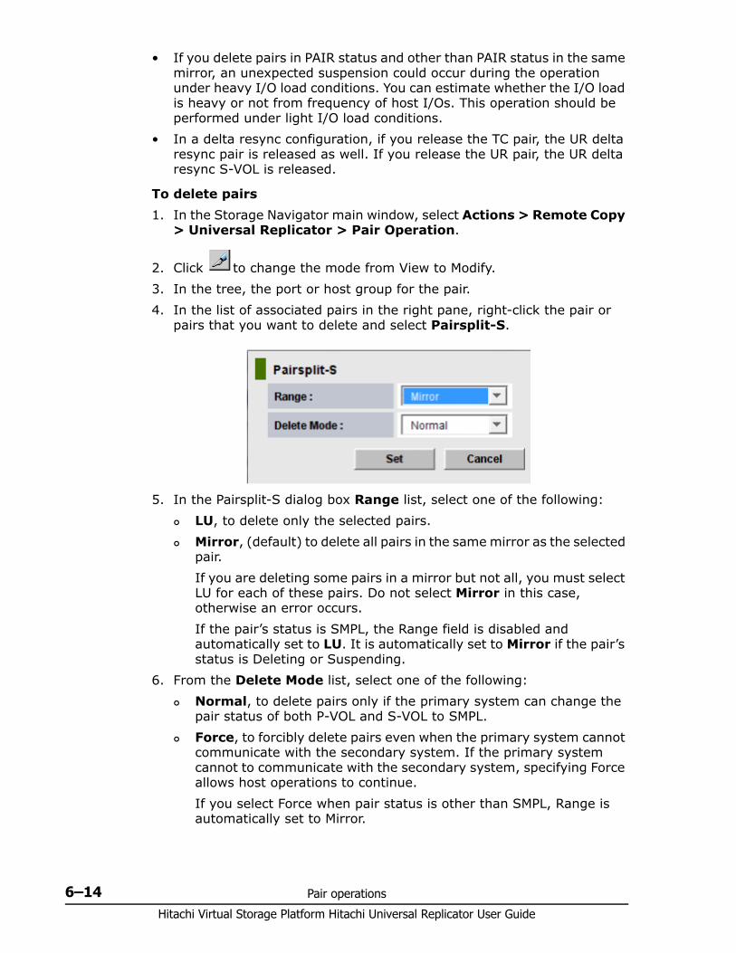
Hitachi Virtual Storage Platform Hitachi Universal Replicator User Guide
6–14 Pair operations
• If you delete pairs in PAIR status and other than PAIR status in the same mirror, an unexpected suspension could occur during the operation under heavy I/O load conditions. You can estimate whether the I/O load is heavy or not from frequency of host I/Os. This operation should be performed under light I/O load conditions.
• In a delta resync configuration, if you release the TC pair, the UR delta resync pair is released as well. If you release the UR pair, the UR delta resync S-VOL is released.
To delete pairs1. In the Storage Navigator main window, select Actions > Remote Copy
> Universal Replicator > Pair Operation.
2. Click to change the mode from View to Modify.3. In the tree, the port or host group for the pair. 4. In the list of associated pairs in the right pane, right-click the pair or
pairs that you want to delete and select Pairsplit-S.
5. In the Pairsplit-S dialog box Range list, select one of the following: LU, to delete only the selected pairs. Mirror, (default) to delete all pairs in the same mirror as the selected
pair.If you are deleting some pairs in a mirror but not all, you must select LU for each of these pairs. Do not select Mirror in this case, otherwise an error occurs.If the pair’s status is SMPL, the Range field is disabled and automatically set to LU. It is automatically set to Mirror if the pair’s status is Deleting or Suspending.
6. From the Delete Mode list, select one of the following: Normal, to delete pairs only if the primary system can change the
pair status of both P-VOL and S-VOL to SMPL. Force, to forcibly delete pairs even when the primary system cannot
communicate with the secondary system. If the primary system cannot to communicate with the secondary system, specifying Force allows host operations to continue.If you select Force when pair status is other than SMPL, Range is automatically set to Mirror.

Pair operations 6–15Hitachi Virtual Storage Platform Hitachi Universal Replicator User Guide
If you select Force when Range is set to LU, the other pairs in the same journal are also suspended.
7. Click Set.8. Review settings in the Preview list in the Journal Operation window.
To modify a setting, right click and select Modify. To cancel a setting, right click and select Cancel.
9. Click Apply to delete the pairs.
Deleting pairs in a mirror When you delete the pairs in a mirror, data copying between master and restore journals ends.
Prerequisite information
This operation can be performed from the primary or secondary system.
The following information may be useful to you before beginning the procedure:
If a journal includes two mirrors:• If you specify a mirror in Hold, Holding, or Hold(Failure) status, only the
UR pairs of the specified mirror are deleted.• If you specify a mirror that is not in Hold, Holding, or Hold(Failure)
status, UR pairs of both mirrors (including the mirror that you did not specify) are deleted.
To delete pairs in a mirror1. In the Storage Navigator main window, select Actions > Remote Copy
> Universal Replicator > Journal Operation.
2. Click to change the mode from View to Modify.3. Do one of the following:
Caution: Please note the following:• Forced deletion in the local system results in data that was not
yet sent to the remote system being deleted.• Forced deletion in the remote system results in data that was not
yet restored being deleted.• If pair status has not changed to SMPL five minutes after you
forcibly delete the pair, delete it again.• Make sure not to recreate the pair in the first five minutes after
forcibly deleting it using the same journals (mirrors), even if pair status is SMPL and journal status is Initial: in this case pair creation could fail and the pair might suspend.
• A time-out error can occur at the time of a forced deletion if I/O is sent to another pair in the same journal, and the pair’s status is PAIR or COPY.
Hitachi Virtual Storage Platform Hitachi Universal Replicator User Guide
6–16 Pair operations
In the tree, select a master journal or a restore journal from below Registered > LDKC00.
In the tree, expand Registered and then select a master journal or a restore journal from the list in the right pane.
4. From the list of mirrors in the right pane, select the mirrors from which to delete pairs. Each row in the list represents one mirror.
5. Right-click and select Mirror > Pairsplit-S from the menu. 6. Review settings in the Preview list in the Journal Operation window.
To modify a setting, right click and select Modify. To cancel a setting, right click and select Cancel.
7. Click Apply to delete the pairs in the mirror.
Caution: If the journal (mirror) status is not Initial—even though you deleted pairs forcibly and five minutes have passed—perform the operation again to delete all pairs registered to the mirror.
Do not create pairs with the same journal for at least five minutes, even if the journal status was Initial; otherwise pair creation could fail and the pair would be suspended.

7
Monitoring the system 7–1Hitachi Virtual Storage Platform Hitachi Universal Replicator User Guide
Monitoring the system
Monitoring pairs, journals, data paths, I/O, and hardware performance is crucial for ensuring that Universal Replicator pairs continue to function correctly.
This topic provides information and instructions for monitoring a Universal Replicator system.
□ Monitoring pair activity and status
□ Saving pair information to a text file
□ Monitoring copy operations data, I/O with Usage Monitor
□ Monitoring I/O and hardware performance with Performance Monitor
□ Monitoring journal (mirror) status
□ Monitoring logical path status
□ History of pair operations
Hitachi Virtual Storage Platform Hitachi Universal Replicator User Guide
7–2 Monitoring the system
Monitoring pair activity and statusMonitoring the Universal Replicator system is essential for maintaining your pairs.• Each operation requires a specific status or statuses. Before performing
a pair operation, check the pair’s status. • Pair status changes when an operation is performed. Check status to
make sure that pairs are operating correctly and that data is updated from P-VOLs to S-VOLs, and that differential data is managed appropriately.
Frequent monitoring of the system is optional but recommended. You can set up automatic e-mail notification from the SN for problems found during monitoring (see Hitachi Storage Navigator User Guide).
To monitor pair activity 1. In the Storage Navigator main window, click Actions > Remote Copy
> Universal Replicator > Pair Operation. 2. In the Pair Operation window, locate the pair whose status you want to
review and check its status in the Status column.3. To filter the list, click Display Filter. Headings are described in Display
Filter dialog box on page E-23 and the Help.4. To export pair information, see Saving pair information to a text file on
page 7-10.5. To view more detailed pair information, right click a pair and then select
Pair Status from the menu.
Pair status definitionsBoth Storage Navigator and CCI pair status names appear in the Storage Navigator Status columns, except when the names are the same. When they are the same, the CCI status does not appear.
The following table shows both types of status names and their descriptions. In some cases, a particular status has no exact parallel status in the other interface. This is noted.
When checking your pairs’ status, click File/Refresh to make sure the data is current.
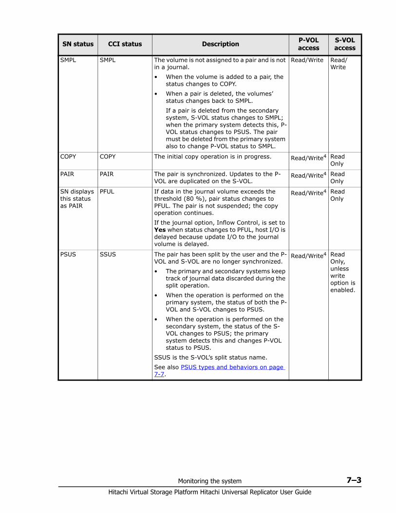
Monitoring the system 7–3Hitachi Virtual Storage Platform Hitachi Universal Replicator User Guide
SN status CCI status Description P-VOL access
S-VOL access
SMPL SMPL The volume is not assigned to a pair and is not in a journal.• When the volume is added to a pair, the
status changes to COPY.• When a pair is deleted, the volumes’
status changes back to SMPL.If a pair is deleted from the secondary system, S-VOL status changes to SMPL; when the primary system detects this, P-VOL status changes to PSUS. The pair must be deleted from the primary system also to change P-VOL status to SMPL.
Read/Write Read/Write
COPY COPY The initial copy operation is in progress. Read/Write4 Read Only
PAIR PAIR The pair is synchronized. Updates to the P-VOL are duplicated on the S-VOL.
Read/Write4 Read Only
SN displays this status as PAIR
PFUL If data in the journal volume exceeds the threshold (80 %), pair status changes to PFUL. The pair is not suspended; the copy operation continues.If the journal option, Inflow Control, is set to Yes when status changes to PFUL, host I/O is delayed because update I/O to the journal volume is delayed.
Read/Write4 Read Only
PSUS SSUS The pair has been split by the user and the P-VOL and S-VOL are no longer synchronized. • The primary and secondary systems keep
track of journal data discarded during the split operation.
• When the operation is performed on the primary system, the status of both the P-VOL and S-VOL changes to PSUS.
• When the operation is performed on the secondary system, the status of the S-VOL changes to PSUS; the primary system detects this and changes P-VOL status to PSUS.
SSUS is the S-VOL’s split status name.See also PSUS types and behaviors on page 7-7.
Read/Write4 Read Only, unless write option is enabled.
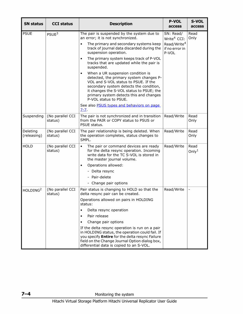
Hitachi Virtual Storage Platform Hitachi Universal Replicator User Guide
7–4 Monitoring the system
PSUE PSUE3 The pair is suspended by the system due to an error; it is not synchronized.• The primary and secondary systems keep
track of journal data discarded during the suspension operation.
• The primary system keeps track of P-VOL tracks that are updated while the pair is suspended.
• When a UR suspension condition is detected, the primary system changes P-VOL and S-VOL status to PSUE. If the secondary system detects the condition, it changes the S-VOL status to PSUE; the primary system detects this and changes P-VOL status to PSUE.
See also PSUS types and behaviors on page 7-7.
SN: Read/Write4 CCI: Read/Write4 if no error in P-VOL
Read Only
Suspending (No parallel CCI status)
The pair is not synchronized and in transition from the PAIR or COPY status to PSUS or PSUE status.
Read/Write Read Only
Deleting (releasing)
(No parallel CCI status)
The pair relationship is being deleted. When the operation completes, status changes to SMPL.
Read/Write Read Only
HOLD (No parallel CCI status)
• The pair or command devices are ready for the delta resync operation. Incoming write data for the TC S-VOL is stored in the master journal volume.
• Operations allowed:- Delta resync- Pair-delete- Change pair options
Read/Write Read Only1
HOLDING2 (No parallel CCI status)
Pair status is changing to HOLD so that the delta resync pair can be created. Operations allowed on pairs in HOLDING status:• Delta resync operation• Pair release• Change pair options If the delta resync operation is run on a pair in HOLDING status, the operation could fail. If you specify Entire for the delta resync Failure field on the Change Journal Option dialog box, differential data is copied to an S-VOL.
Read/Write -
SN status CCI status Description P-VOL access
S-VOL access
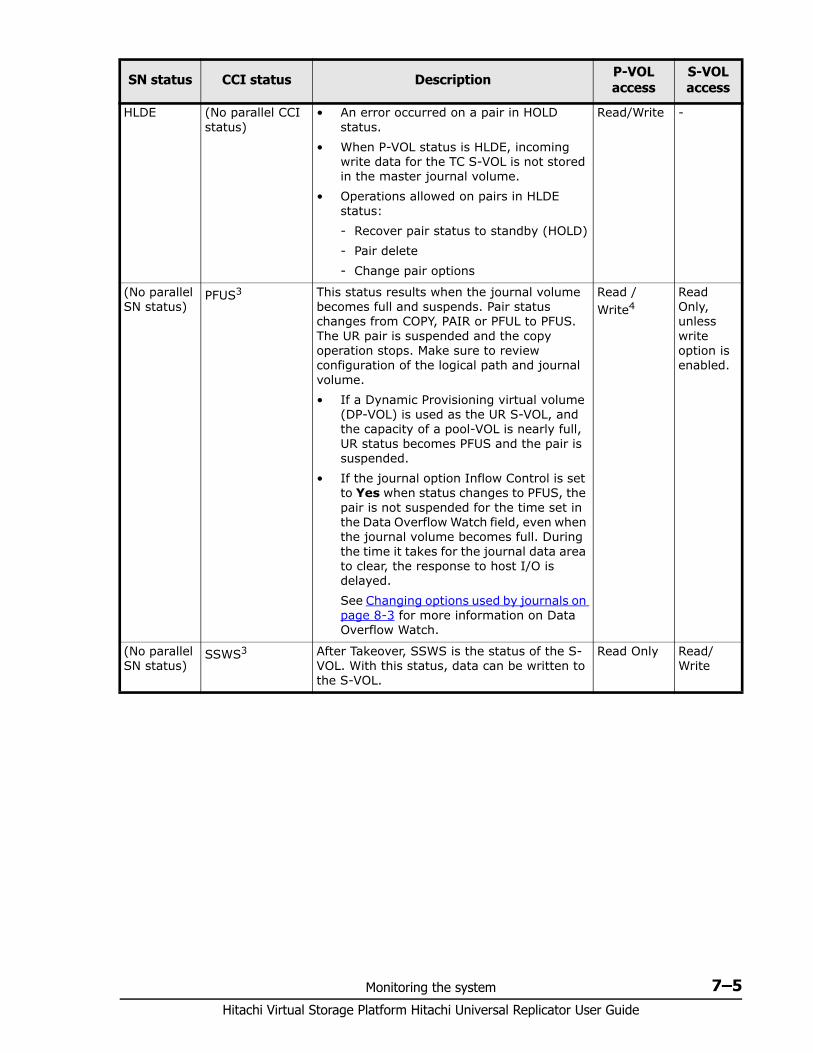
Monitoring the system 7–5Hitachi Virtual Storage Platform Hitachi Universal Replicator User Guide
HLDE (No parallel CCI status)
• An error occurred on a pair in HOLD status.
• When P-VOL status is HLDE, incoming write data for the TC S-VOL is not stored in the master journal volume.
• Operations allowed on pairs in HLDE status:- Recover pair status to standby (HOLD)- Pair delete- Change pair options
Read/Write -
(No parallel SN status)
PFUS3 This status results when the journal volume becomes full and suspends. Pair status changes from COPY, PAIR or PFUL to PFUS. The UR pair is suspended and the copy operation stops. Make sure to review configuration of the logical path and journal volume.• If a Dynamic Provisioning virtual volume
(DP-VOL) is used as the UR S-VOL, and the capacity of a pool-VOL is nearly full, UR status becomes PFUS and the pair is suspended.
• If the journal option Inflow Control is set to Yes when status changes to PFUS, the pair is not suspended for the time set in the Data Overflow Watch field, even when the journal volume becomes full. During the time it takes for the journal data area to clear, the response to host I/O is delayed. See Changing options used by journals on page 8-3 for more information on Data Overflow Watch.
Read /Write4
Read Only, unless write option is enabled.
(No parallel SN status)
SSWS3 After Takeover, SSWS is the status of the S-VOL. With this status, data can be written to the S-VOL.
Read Only Read/Write
SN status CCI status Description P-VOL access
S-VOL access
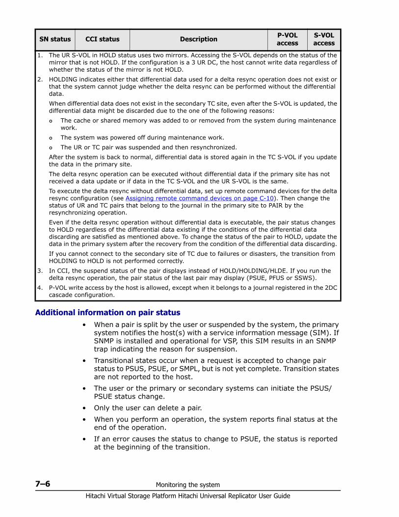
Hitachi Virtual Storage Platform Hitachi Universal Replicator User Guide
7–6 Monitoring the system
Additional information on pair status• When a pair is split by the user or suspended by the system, the primary
system notifies the host(s) with a service information message (SIM). If SNMP is installed and operational for VSP, this SIM results in an SNMP trap indicating the reason for suspension.
• Transitional states occur when a request is accepted to change pair status to PSUS, PSUE, or SMPL, but is not yet complete. Transition states are not reported to the host.
• The user or the primary or secondary systems can initiate the PSUS/PSUE status change.
• Only the user can delete a pair. • When you perform an operation, the system reports final status at the
end of the operation. • If an error causes the status to change to PSUE, the status is reported
at the beginning of the transition.
1. The UR S-VOL in HOLD status uses two mirrors. Accessing the S-VOL depends on the status of the mirror that is not HOLD. If the configuration is a 3 UR DC, the host cannot write data regardless of whether the status of the mirror is not HOLD.
2. HOLDING indicates either that differential data used for a delta resync operation does not exist or that the system cannot judge whether the delta resync can be performed without the differential data. When differential data does not exist in the secondary TC site, even after the S-VOL is updated, the differential data might be discarded due to the one of the following reasons: The cache or shared memory was added to or removed from the system during maintenance
work. The system was powered off during maintenance work. The UR or TC pair was suspended and then resynchronized.
After the system is back to normal, differential data is stored again in the TC S-VOL if you update the data in the primary site.The delta resync operation can be executed without differential data if the primary site has not received a data update or if data in the TC S-VOL and the UR S-VOL is the same. To execute the delta resync without differential data, set up remote command devices for the delta resync configuration (see Assigning remote command devices on page C-10). Then change the status of UR and TC pairs that belong to the journal in the primary site to PAIR by the resynchronizing operation.Even if the delta resync operation without differential data is executable, the pair status changes to HOLD regardless of the differential data existing if the conditions of the differential data discarding are satisfied as mentioned above. To change the status of the pair to HOLD, update the data in the primary system after the recovery from the condition of the differential data discarding. If you cannot connect to the secondary site of TC due to failures or disasters, the transition from HOLDING to HOLD is not performed correctly.
3. In CCI, the suspend status of the pair displays instead of HOLD/HOLDING/HLDE. If you run the delta resync operation, the pair status of the last pair may display (PSUE, PFUS or SSWS).
4. P-VOL write access by the host is allowed, except when it belongs to a journal registered in the 2DC cascade configuration.
SN status CCI status Description P-VOL access
S-VOL access
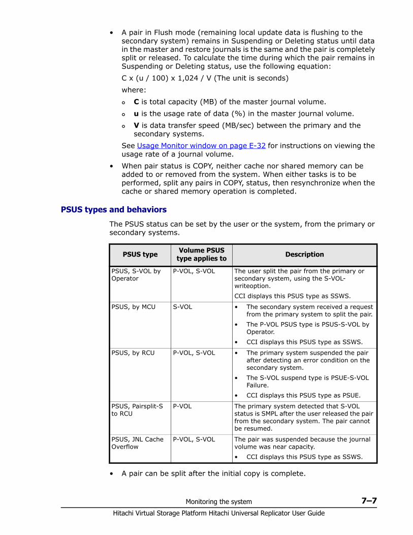
Monitoring the system 7–7Hitachi Virtual Storage Platform Hitachi Universal Replicator User Guide
• A pair in Flush mode (remaining local update data is flushing to the secondary system) remains in Suspending or Deleting status until data in the master and restore journals is the same and the pair is completely split or released. To calculate the time during which the pair remains in Suspending or Deleting status, use the following equation:C x (u / 100) x 1,024 / V (The unit is seconds)where: C is total capacity (MB) of the master journal volume. u is the usage rate of data (%) in the master journal volume. V is data transfer speed (MB/sec) between the primary and the
secondary systems.See Usage Monitor window on page E-32 for instructions on viewing the usage rate of a journal volume.
• When pair status is COPY, neither cache nor shared memory can be added to or removed from the system. When either tasks is to be performed, split any pairs in COPY, status, then resynchronize when the cache or shared memory operation is completed.
PSUS types and behaviors
The PSUS status can be set by the user or the system, from the primary or secondary systems.
• A pair can be split after the initial copy is complete.
PSUS type Volume PSUS type applies to Description
PSUS, S-VOL by Operator
P-VOL, S-VOL The user split the pair from the primary or secondary system, using the S-VOL-writeoption.CCI displays this PSUS type as SSWS.
PSUS, by MCU S-VOL • The secondary system received a request from the primary system to split the pair.
• The P-VOL PSUS type is PSUS-S-VOL by Operator.
• CCI displays this PSUS type as SSWS.
PSUS, by RCU P-VOL, S-VOL • The primary system suspended the pair after detecting an error condition on the secondary system.
• The S-VOL suspend type is PSUE-S-VOL Failure.
• CCI displays this PSUS type as PSUE.
PSUS, Pairsplit-S to RCU
P-VOL The primary system detected that S-VOL status is SMPL after the user released the pair from the secondary system. The pair cannot be resumed.
PSUS, JNL Cache Overflow
P-VOL, S-VOL The pair was suspended because the journal volume was near capacity. • CCI displays this PSUS type as SSWS.
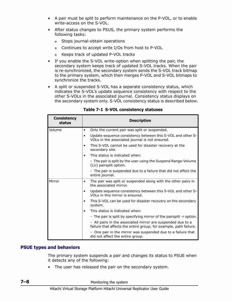
Hitachi Virtual Storage Platform Hitachi Universal Replicator User Guide
7–8 Monitoring the system
• A pair must be split to perform maintenance on the P-VOL, or to enable write-access on the S-VOL.
• After status changes to PSUS, the primary system performs the following tasks: Stops journal-obtain operations Continues to accept write I/Os from host to P-VOL Keeps track of updated P-VOL tracks
• If you enable the S-VOL write-option when splitting the pair, the secondary system keeps track of updated S-VOL tracks. When the pair is re-synchronized, the secondary system sends the S-VOL track bitmap to the primary system, which then merges P-VOL and S-VOL bitmaps to synchronize the tracks.
• A split or suspended S-VOL has a separate consistency status, which indicates the S-VOL’s update sequence consistency with respect to the other S-VOLs in the associated journal. Consistency status displays on the secondary system only. S-VOL consistency status is described below.
Table 7-1 S-VOL consistency statuses
PSUE types and behaviors
The primary system suspends a pair and changes its status to PSUE when it detects any of the following:• The user has released the pair on the secondary system.
Consistency status Description
Volume • Only the current pair was split or suspended. • Update sequence consistency between this S-VOL and other S-
VOLs in the associated journal is not ensured. • This S-VOL cannot be used for disaster recovery at the
secondary site. • This status is indicated when:
- The pair is split by the user using the Suspend Range-Volume (LU) pairsplit option. - The pair is suspended due to a failure that did not affect the entire journal.
Mirror • The pair was split or suspended along with the other pairs in the associated mirror.
• Update sequence consistency between this S-VOL and other S-VOLs in this mirror is ensured.
• This S-VOL can be used for disaster recovery on the secondary system.
• This status is indicated when: - The pair is split by specifying mirror of the pairsplit -r option.- All pairs in the associated mirror are suspended due to a failure that affects the entire group; for example, path failure. - One pair in the mirror was suspended due to a failure that did not affect the entire group.
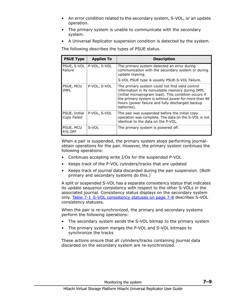
Monitoring the system 7–9Hitachi Virtual Storage Platform Hitachi Universal Replicator User Guide
• An error condition related to the secondary system, S-VOL, or an update operation.
• The primary system is unable to communicate with the secondary system.
• A Universal Replicator suspension condition is detected by the system.
The following describes the types of PSUE status.
When a pair is suspended, the primary system stops performing journal-obtain operations for the pair. However, the primary system continues the following operations:• Continues accepting write I/Os for the suspended P-VOL• Keeps track of the P-VOL cylinders/tracks that are updated• Keeps track of journal data discarded during the pair suspension. (Both
primary and secondary systems do this.)
A split or suspended S-VOL has a separate consistency status that indicates its update sequence consistency with respect to the other S-VOLs in the associated journal. Consistency status displays on the secondary system only. Table 7-1 S-VOL consistency statuses on page 7-8 describes S-VOL consistency statuses.
When the pair is re-synchronized, the primary and secondary systems perform the following operations:• The secondary system sends the S-VOL bitmap to the primary system• The primary system merges the P-VOL and S-VOL bitmaps to
synchronize the tracks
These actions ensure that all cylinders/tracks containing journal data discarded on the secondary system are re-synchronized.
PSUE Type Applies To Description
PSUE, S-VOL Failure
P-VOL, S-VOL The primary system detected an error during communication with the secondary system or during update copying. S-VOL PSUE type is usually PSUE-S-VOL Failure.
PSUE, MCU IMPL
P-VOL, S-VOL The primary system could not find valid control information in its nonvolatile memory during IMPL (initial microprogram load). This condition occurs if the primary system is without power for more than 48 hours (power failure and fully discharged backup batteries).
PSUE, Initial Copy Failed
P-VOL, S-VOL The pair was suspended before the initial copy operation was complete. The data on the S-VOL is not identical to the data on the P-VOL.
PSUE, MCU P/S OFF
S-VOL The primary system is powered off.
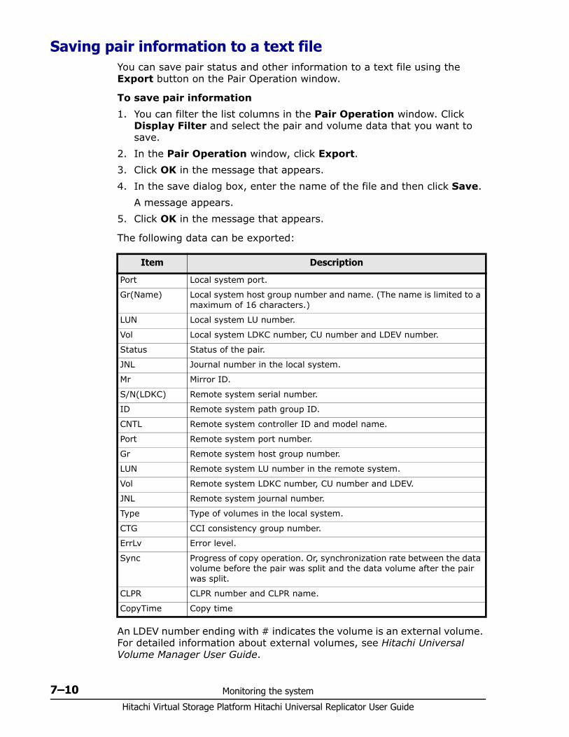
Hitachi Virtual Storage Platform Hitachi Universal Replicator User Guide
7–10 Monitoring the system
Saving pair information to a text file You can save pair status and other information to a text file using the Export button on the Pair Operation window.
To save pair information1. You can filter the list columns in the Pair Operation window. Click
Display Filter and select the pair and volume data that you want to save.
2. In the Pair Operation window, click Export.3. Click OK in the message that appears.4. In the save dialog box, enter the name of the file and then click Save.
A message appears.5. Click OK in the message that appears.
The following data can be exported:
An LDEV number ending with # indicates the volume is an external volume. For detailed information about external volumes, see Hitachi Universal Volume Manager User Guide.
Item Description
Port Local system port.
Gr(Name) Local system host group number and name. (The name is limited to a maximum of 16 characters.)
LUN Local system LU number.
Vol Local system LDKC number, CU number and LDEV number.
Status Status of the pair.
JNL Journal number in the local system.
Mr Mirror ID.
S/N(LDKC) Remote system serial number.
ID Remote system path group ID.
CNTL Remote system controller ID and model name.
Port Remote system port number.
Gr Remote system host group number.
LUN Remote system LU number in the remote system.
Vol Remote system LDKC number, CU number and LDEV.
JNL Remote system journal number.
Type Type of volumes in the local system.
CTG CCI consistency group number.
ErrLv Error level.
Sync Progress of copy operation. Or, synchronization rate between the data volume before the pair was split and the data volume after the pair was split.
CLPR CLPR number and CLPR name.
CopyTime Copy time
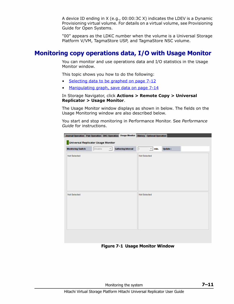
Monitoring the system 7–11Hitachi Virtual Storage Platform Hitachi Universal Replicator User Guide
A device ID ending in X (e.g., 00:00:3C X) indicates the LDEV is a Dynamic Provisioning virtual volume. For details on a virtual volume, see Provisioning Guide for Open Systems.
"00" appears as the LDKC number when the volume is a Universal Storage Platform V/VM, TagmaStore USP, and TagmaStore NSC volume.
Monitoring copy operations data, I/O with Usage MonitorYou can monitor and use operations data and I/O statistics in the Usage Monitor window.
This topic shows you how to do the following:• Selecting data to be graphed on page 7-12• Manipulating graph, save data on page 7-14
In Storage Navigator, click Actions > Remote Copy > Universal Replicator > Usage Monitor.
The Usage Monitor window displays as shown in below. The fields on the Usage Monitoring window are also described below.
You start and stop monitoring in Performance Monitor. See Performance Guide for instructions.
Figure 7-1 Usage Monitor Window
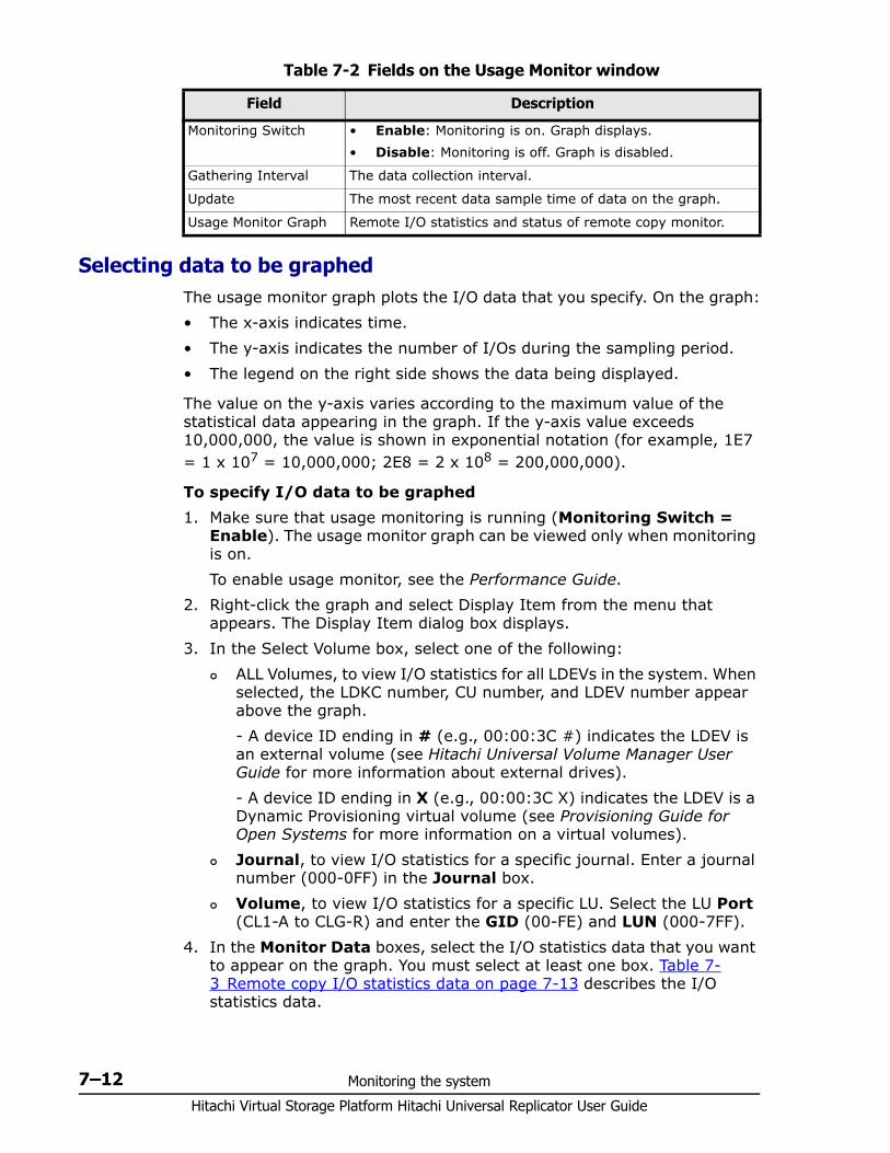
Hitachi Virtual Storage Platform Hitachi Universal Replicator User Guide
7–12 Monitoring the system
Table 7-2 Fields on the Usage Monitor window
Selecting data to be graphedThe usage monitor graph plots the I/O data that you specify. On the graph:• The x-axis indicates time.• The y-axis indicates the number of I/Os during the sampling period.• The legend on the right side shows the data being displayed.
The value on the y-axis varies according to the maximum value of the statistical data appearing in the graph. If the y-axis value exceeds 10,000,000, the value is shown in exponential notation (for example, 1E7 = 1 x 107 = 10,000,000; 2E8 = 2 x 108 = 200,000,000).
To specify I/O data to be graphed1. Make sure that usage monitoring is running (Monitoring Switch =
Enable). The usage monitor graph can be viewed only when monitoring is on.To enable usage monitor, see the Performance Guide.
2. Right-click the graph and select Display Item from the menu that appears. The Display Item dialog box displays.
3. In the Select Volume box, select one of the following: ALL Volumes, to view I/O statistics for all LDEVs in the system. When
selected, the LDKC number, CU number, and LDEV number appear above the graph.- A device ID ending in # (e.g., 00:00:3C #) indicates the LDEV is an external volume (see Hitachi Universal Volume Manager User Guide for more information about external drives).- A device ID ending in X (e.g., 00:00:3C X) indicates the LDEV is a Dynamic Provisioning virtual volume (see Provisioning Guide for Open Systems for more information on a virtual volumes).
Journal, to view I/O statistics for a specific journal. Enter a journal number (000-0FF) in the Journal box.
Volume, to view I/O statistics for a specific LU. Select the LU Port (CL1-A to CLG-R) and enter the GID (00-FE) and LUN (000-7FF).
4. In the Monitor Data boxes, select the I/O statistics data that you want to appear on the graph. You must select at least one box. Table 7-3 Remote copy I/O statistics data on page 7-13 describes the I/O statistics data.
Field Description
Monitoring Switch • Enable: Monitoring is on. Graph displays.• Disable: Monitoring is off. Graph is disabled.
Gathering Interval The data collection interval.
Update The most recent data sample time of data on the graph.
Usage Monitor Graph Remote I/O statistics and status of remote copy monitor.
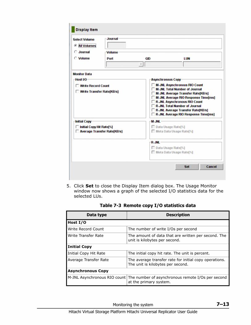
Monitoring the system 7–13Hitachi Virtual Storage Platform Hitachi Universal Replicator User Guide
5. Click Set to close the Display Item dialog box. The Usage Monitor window now shows a graph of the selected I/O statistics data for the selected LUs.
Table 7-3 Remote copy I/O statistics data
Data type Description
Host I/O
Write Record Count The number of write I/Os per second
Write Transfer Rate The amount of data that are written per second. The unit is kilobytes per second.
Initial Copy
Initial Copy Hit Rate The initial copy hit rate. The unit is percent.
Average Transfer Rate The average transfer rate for initial copy operations. The unit is kilobytes per second.
Asynchronous Copy
M-JNL Asynchronous RIO count The number of asynchronous remote I/Os per second at the primary system.
Hitachi Virtual Storage Platform Hitachi Universal Replicator User Guide
7–14 Monitoring the system
Manipulating graph, save data• To enlarge the graph, right-click it and select Large Size.• To close the graph, right-click it and select Close.• To save monitoring data in text files, use the Performance Monitor Export
Tool.
Monitoring I/O and hardware performance with Performance Monitor
Performance Monitor software provides detailed information on I/O activity and hardware performance in the VSP systems. Storage system usage and performance data that is collected and displayed by Performance Monitor enables you to:• Identify the optimum timing for performing Universal Replicator copy
operations.• Determine the best locations for the Universal Replicator S-VOLs (for
example; parity groups with less frequently accessed volumes to avoid bottlenecks of back-end activity)
• Monitor system performance during Universal Replicator operations and during testing activities.
M-JNL Total Number of Journal The number of journals at the primary system.
M-JNL Average Transfer Rate The average transfer rate for journals in the primary system. The unit is kilobytes per second.
M-JNL Average RIO Response The remote I/O process time on the primary system. The unit is milliseconds.
R-JNL Asynchronous RIO count The number of asynchronous remote I/Os per second at the secondary system.
R-JNL Total Number of Journal The number of journals at the secondary system.
R-JNL Average Transfer Rate The average transfer rate for journals in the secondary system. The unit is kilobytes per second.
R-JNL Average RIO Response The remote I/O process time on the secondary system. The unit is milliseconds.
M-JNL
Data Used Rate Data usage rate for master journals. The unit is percent.
Meta Data Used Rate Metadata usage rate for master journals. The unit is percent.
R-JNL
Data Used Rate Data usage rate for restore journals. The unit is percent.
Meta Data Used Rate Metadata usage rate for restore journals. The unit is percent.
Data type Description
Monitoring the system 7–15Hitachi Virtual Storage Platform Hitachi Universal Replicator User Guide
Use the following procedure to lessen the impact on Universal Replicator operations while Performance Monitor is collecting data for one or more systems on the same VSP internal LAN:1. If Performance Monitor is collecting high amounts of LDEV data,
disabling this activity, if possible, for one or more systems.2. If Performance Monitor is collecting data for more than three systems on
the VSP internal LAN, disconnect Performance Monitor, if possible, from one or more systems before using Universal Replicator.
3. After you have disabled LDEV data collection and/or disconnected Performance Monitor wherever possible, then connect to the system using Storage Navigator and launch Universal Replicator.
4. When Universal Replicator operations are completed, exit Universal Replicator and Storage Navigator.
5. Re-enable Performance Monitor data collection.
For further information on Performance Monitor, see Performance Guide.
Monitoring journal (mirror) statusThe status of a mirror associated with a journal relates to the pair operations that are performed on the journal. Monitoring these statuses can help you resolve problems and maintain the Universal Replicator system. Status for journals is viewed on the Journal Operation window.
To view journal status1. In Storage Navigator, click Actions > Remote Copy > Universal
Replicator > Journal Operation.2. In the tree, open the Registered > LDKC00 child-tree, then select a
journal. The group’s information displays in the right-hand pane. See the Status column.
The mirror status for both Storage Navigator and CCI appear together in the Status column. However, the definitions are presented seperately in the following topics because there is not a one-to-one relationship between them. Numerous CCI mirror statuses can be paired with Storage Navigator statuses. For mirror status definitions, see:• Storage Navigator mirror status definitions on page 7-15• CCI mirror status definitions on page 7-16
Storage Navigator mirror status definitionsCCI mirror statuses appear beside Storage Navigator statuses in the SN/CCI format. The following describe Storage Navigator statuses.
Status Description
Initial Data volumes are registered in the mirror.
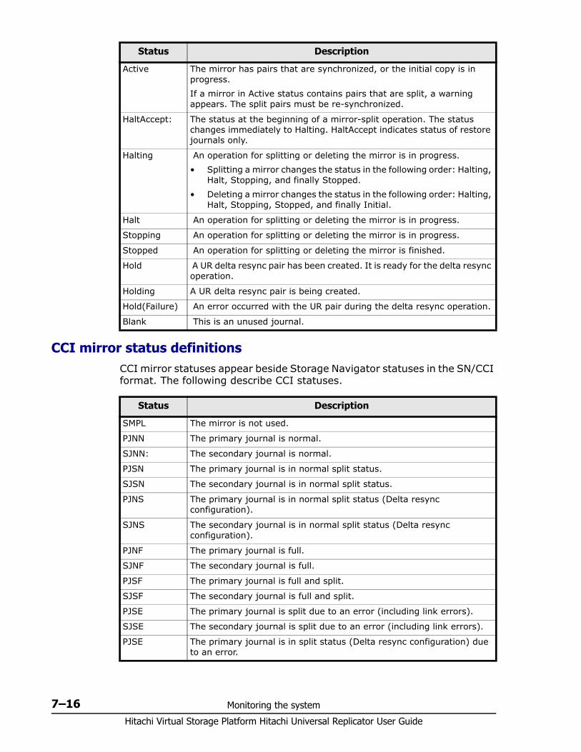
Hitachi Virtual Storage Platform Hitachi Universal Replicator User Guide
7–16 Monitoring the system
CCI mirror status definitionsCCI mirror statuses appear beside Storage Navigator statuses in the SN/CCI format. The following describe CCI statuses.
Active The mirror has pairs that are synchronized, or the initial copy is in progress. If a mirror in Active status contains pairs that are split, a warning appears. The split pairs must be re-synchronized.
HaltAccept: The status at the beginning of a mirror-split operation. The status changes immediately to Halting. HaltAccept indicates status of restore journals only.
Halting An operation for splitting or deleting the mirror is in progress. • Splitting a mirror changes the status in the following order: Halting,
Halt, Stopping, and finally Stopped. • Deleting a mirror changes the status in the following order: Halting,
Halt, Stopping, Stopped, and finally Initial.
Halt An operation for splitting or deleting the mirror is in progress.
Stopping An operation for splitting or deleting the mirror is in progress.
Stopped An operation for splitting or deleting the mirror is finished.
Hold A UR delta resync pair has been created. It is ready for the delta resync operation.
Holding A UR delta resync pair is being created.
Hold(Failure) An error occurred with the UR pair during the delta resync operation.
Blank This is an unused journal.
Status Description
Status Description
SMPL The mirror is not used.
PJNN The primary journal is normal.
SJNN: The secondary journal is normal.
PJSN The primary journal is in normal split status.
SJSN The secondary journal is in normal split status.
PJNS The primary journal is in normal split status (Delta resync configuration).
SJNS The secondary journal is in normal split status (Delta resync configuration).
PJNF The primary journal is full.
SJNF The secondary journal is full.
PJSF The primary journal is full and split.
SJSF The secondary journal is full and split.
PJSE The primary journal is split due to an error (including link errors).
SJSE The secondary journal is split due to an error (including link errors).
PJSE The primary journal is in split status (Delta resync configuration) due to an error.
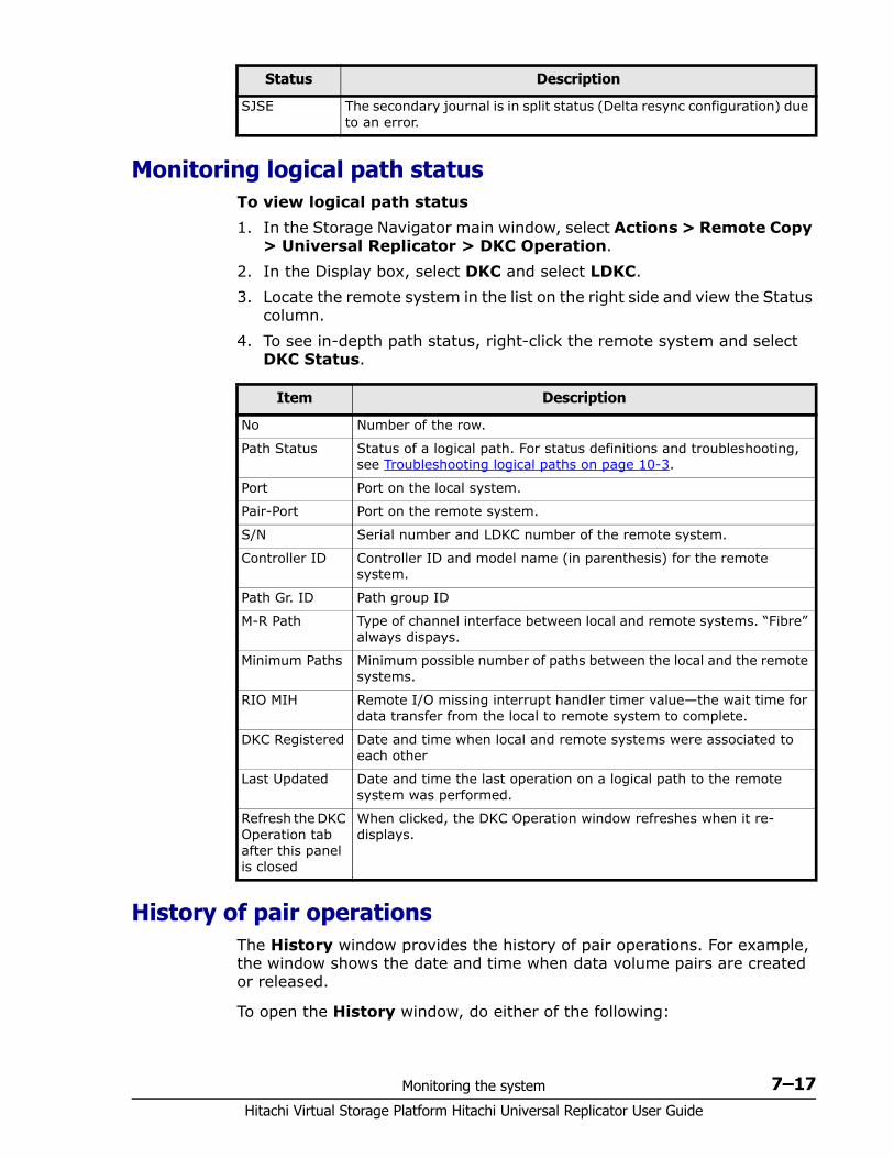
Monitoring the system 7–17Hitachi Virtual Storage Platform Hitachi Universal Replicator User Guide
Monitoring logical path statusTo view logical path status1. In the Storage Navigator main window, select Actions > Remote Copy
> Universal Replicator > DKC Operation.2. In the Display box, select DKC and select LDKC. 3. Locate the remote system in the list on the right side and view the Status
column.4. To see in-depth path status, right-click the remote system and select
DKC Status.
History of pair operationsThe History window provides the history of pair operations. For example, the window shows the date and time when data volume pairs are created or released.
To open the History window, do either of the following:
SJSE The secondary journal is in split status (Delta resync configuration) due to an error.
Status Description
Item Description
No Number of the row.
Path Status Status of a logical path. For status definitions and troubleshooting, see Troubleshooting logical paths on page 10-3.
Port Port on the local system.
Pair-Port Port on the remote system.
S/N Serial number and LDKC number of the remote system.
Controller ID Controller ID and model name (in parenthesis) for the remote system.
Path Gr. ID Path group ID
M-R Path Type of channel interface between local and remote systems. “Fibre” always dispays.
Minimum Paths Minimum possible number of paths between the local and the remote systems.
RIO MIH Remote I/O missing interrupt handler timer value—the wait time for data transfer from the local to remote system to complete.
DKC Registered Date and time when local and remote systems were associated to each other
Last Updated Date and time the last operation on a logical path to the remote system was performed.
Refresh the DKC Operation tab after this panel is closed
When clicked, the DKC Operation window refreshes when it re-displays.
Hitachi Virtual Storage Platform Hitachi Universal Replicator User Guide
7–18 Monitoring the system
If Universal Replicator has not been started:1. In the Storage Navigator main window, select Actions > Remote Copy
> Universal Replicator > History.The History window opens. The History window may not show the latest operation history. To view the latest operation history, go to the next step.
2. Select File > Refresh. The operation history is updated.
If Universal Replicator has already been started:1. Click the History tab to open the History window.
The History window may not show the latest operation history. To view the latest operation history, go to the next step.
2. Select File > Refresh. The operation history is updated.
8
Maintaining the system 8–1Hitachi Virtual Storage Platform Hitachi Universal Replicator User Guide
Maintaining the system
Some maintenance tasks are a response to behavior discovered during system monitoring. However, you can also change certain settings to keep the system in tune with your changing requirements.
This chapter provides information and instructions for maintaining a Universal Replicator system.
□ Pair maintenance—changing the pair-split option
□ Journal and mirror maintenance
□ Logical path maintenance
□ Managing power-off for systems and network devices
Hitachi Virtual Storage Platform Hitachi Universal Replicator User Guide
8–2 Maintaining the system
Pair maintenance—changing the pair-split option You can change the option that specifies whether a pair-split operation that is triggered by pair failure is applied to all the pairs in the mirror, or only to the affected pair. This option was first set during the pair create operation.
Prerequisite information
You can change this option only for pairs in PAIR, PSUS, PSUE, HOLD, HOLDING, or HLDE status.
To change the option1. In the Storage Navigator main window, select Actions > Remote Copy
> Universal Replicator > Pair Operation.
2. Click to change the mode from View to Modify.3. In the tree, select the port that you have configured for the pair, or a
host group (displayed below the ports). The volumes for the port or host group display in the right-side list area,
4. In the list, right-click the desired pair, or mirror of pairs, then select Change Pair Option from the menu.
5. In the Change Pair Option dialog box, click the Error Level list and select one of the following: Mirror, to split all pairs in the failed pair’s mirror LU, to split only the pair that failed
6. Click Set when finished.7. Review settings in the Preview list in the Journal Operation window.
To modify a setting, right click and select Modify. To cancel a setting, right click and select Cancel.
8. Click Apply to apply the settings. If an error occurs, the error code appears in the right-most column of the Preview list. To view detailed information about the error, right click the error code and select Error Detail.
Journal and mirror maintenanceMaintaining journals and mirror consists of the following operations:• Changing options used by journal• Changing options used by mirrors on page 8-5• Deleting journal volumes from a journal on page 8-8• Deleting journals on page 8-9
Note: If you selected multiple pairs and want to change one of the options on the Change Pair Option dialog box but do not intend to change the other option, leave blank the option that you do not want to change.
Maintaining the system 8–3Hitachi Virtual Storage Platform Hitachi Universal Replicator User Guide
Changing options used by journals Most Universal Replicator pair operations are performed on multiple pairs. This is done using journals. You can change the following options that affect the pairs in journals: • Inflow Control—allows you to restrict the inflow of data to allow other
journals with higher priority data unrestricted inflow • Data Overflow Watch—establishes a timeout period• Use of Cache—allows you to store journal data in the cache on the
secondary system
Prerequisite information
Please be aware of the following when changing journal options:• Journal options must be changed on both systems, primary and
secondary.• To change journal options, one of the following conditions must be
satisfied:- The attribute of the journal is Initial.- The status of the journal in the mirror is one of the following: Initial Stopped Hold(Failure)
When one journal uses multiple mirrors, whether you can select Change Journal Option depends on the status of the journal whose mirror is not in Hold, Holding or Hold(Failure) status. For example, if mirrors in the journal are in the Hold and Active status, you can not change the journal option. If mirrors in the journal are in the Hold and Stopped status, you can change the journal option.
• When changing options for multiple journals, you can leave some options unchanged by entering or selecting no value. If you specify a value, it is applied to the selected journals.
To change options for a journal1. In the Storage Navigator main window, select Actions > Remote Copy
> Universal Replicator > Journal Operation. The Journal Operation window displays.
2. Click to change the mode from View to Modify.3. In the tree, right click a journal below Registered > LDKC00 and then
select Journals > Change JNL Option.
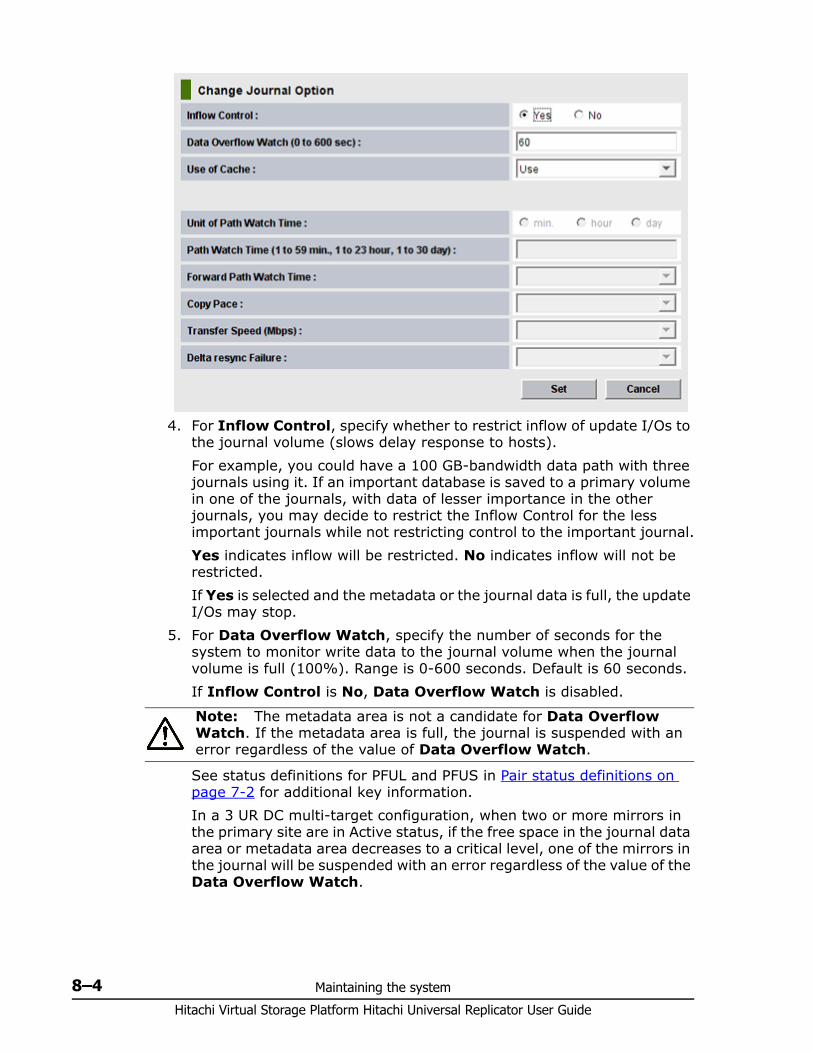
Hitachi Virtual Storage Platform Hitachi Universal Replicator User Guide
8–4 Maintaining the system
4. For Inflow Control, specify whether to restrict inflow of update I/Os to the journal volume (slows delay response to hosts).For example, you could have a 100 GB-bandwidth data path with three journals using it. If an important database is saved to a primary volume in one of the journals, with data of lesser importance in the other journals, you may decide to restrict the Inflow Control for the less important journals while not restricting control to the important journal.Yes indicates inflow will be restricted. No indicates inflow will not be restricted.If Yes is selected and the metadata or the journal data is full, the update I/Os may stop.
5. For Data Overflow Watch, specify the number of seconds for the system to monitor write data to the journal volume when the journal volume is full (100%). Range is 0-600 seconds. Default is 60 seconds. If Inflow Control is No, Data Overflow Watch is disabled.
See status definitions for PFUL and PFUS in Pair status definitions on page 7-2 for additional key information.In a 3 UR DC multi-target configuration, when two or more mirrors in the primary site are in Active status, if the free space in the journal data area or metadata area decreases to a critical level, one of the mirrors in the journal will be suspended with an error regardless of the value of the Data Overflow Watch.
Note: The metadata area is not a candidate for Data Overflow Watch. If the metadata area is full, the journal is suspended with an error regardless of the value of Data Overflow Watch.
Maintaining the system 8–5Hitachi Virtual Storage Platform Hitachi Universal Replicator User Guide
6. For Use of Cache, specify whether to store journal data (initial copy or resynchronization data) in the cache memory on the remote side (restore journal).- Use: Journal data will be stored in the cache. When there is insufficient space in the cache, journal data will also be stored into the journal volume. This setting only takes effect on the journal volumes of RAID-5 or RAID-6.- Not Use: Journal data is not stored in the cache.- Blank: The current setting of Use of Cache will remain unchanged.
7. Click Set when finished.8. Review settings in the Preview list in the Journal Operation window.
To modify a setting, right click and select Modify. To cancel a setting, right click and select Cancel.
9. Click Apply to apply the settings. If an error occurs, the error code appears in the right-most column of the Preview list. To view detailed information about the error, right click the error code and select Error Detail.
Changing options used by mirrors Most pair operations are performed on multiple pairs. This is done using a journal or mirrors. You can change the following options that affect the pairs in a mirror: • Unit of Path Watch Time—establishes the unit of path watch time.• Copy Pace—establishes the pace at which data is copied• Path Watch Time—establishes the amount of time before a blocked path
results in the mirror being split• Forward Path Watch Time—establishes whether to forward the Path
Watch Time value of the master journal to the restore journal.• Transfer Speed—which specifies the speed for data transfer• Delta Resync Failure—which specifies the processing that takes place in
the event of a failure.
Prerequisite information
Please be aware of the following when changing mirror options:• Mirror options can be changed on both primary and secondary systems.• To change mirror options, the status of the mirror must be one of the
following: Initial Active Stopped
Note: This setting does not effect master journals unless the CCI horctakeover command is used to change a master journal into a restore journal.
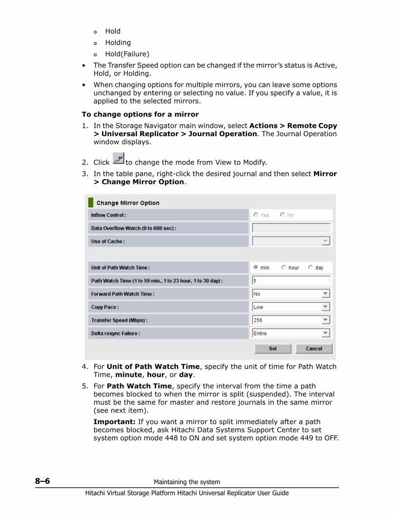
Hitachi Virtual Storage Platform Hitachi Universal Replicator User Guide
8–6 Maintaining the system
Hold Holding Hold(Failure)
• The Transfer Speed option can be changed if the mirror’s status is Active, Hold, or Holding.
• When changing options for multiple mirrors, you can leave some options unchanged by entering or selecting no value. If you specify a value, it is applied to the selected mirrors.
To change options for a mirror1. In the Storage Navigator main window, select Actions > Remote Copy
> Universal Replicator > Journal Operation. The Journal Operation window displays.
2. Click to change the mode from View to Modify.3. In the table pane, right-click the desired journal and then select Mirror
> Change Mirror Option.
4. For Unit of Path Watch Time, specify the unit of time for Path Watch Time, minute, hour, or day.
5. For Path Watch Time, specify the interval from the time a path becomes blocked to when the mirror is split (suspended). The interval must be the same for master and restore journals in the same mirror (see next item).Important: If you want a mirror to split immediately after a path becomes blocked, ask Hitachi Data Systems Support Center to set system option mode 448 to ON and set system option mode 449 to OFF.
Maintaining the system 8–7Hitachi Virtual Storage Platform Hitachi Universal Replicator User Guide
6. For Forward Path Watch Time, specify whether to forward the Path Watch Time value of the master journal to the restore journal. If the Path Watch Time value is forwarded from the master journal to the restore journal, the two journals will have the same Path Watch Time value.- Yes: The Path Watch Time value will be forwarded to the restore journal. - No: The Path Watch Time value will not be forwarded to the restore journal. No is the default.- Blank: The current setting of Forward Path Watch Time will remain unchanged.
7. For Copy Pace, specify the pace for initial copy activity per volume. This field cannot be specified on the remote system. Low is the default. When specifying Medium, ensure that write I/O is 10 MB/s or less per parity group. If it exceeds 10 MB/s, pairs may be suspended. When specifying High, ensure that I/O will not occur. If update I/O occurs, pairs may be suspended.
8. For Transfer Speed, specify the line speed (in Mbps (megabits per second)) of data transfer. Specify one of the following: 256, 100, or 10. Recommended values are:Use 10 when the transfer speed is 10 to 99 Mbps.Use 100 when the transfer speed is 100 to 255 Mbps.Use 256 when the transfer speed is 256 Mbps or higher.
9. For Delta resync Failure, specify the processing that takes place when the delta resync operation cannot be performed. This option is specified on the primary site only. Entire, the default. The entire P-VOL is copied to the S-VOL. None: No processing is performed; the S-VOL is not updated.
Select None if the delta resync S-VOL is shared in one of the following combinations:- An SI P-VOL and a DP-VOL- An SS P-VOL and a DP-VOL- A TI P-VOL and a DP-VOLWith these combinations, selecting Entire results in a failed full copy. With None, recover the delta resync S-VOL by deleting the in-system pairs, copying the delta resync P-VOL to the S-VOL, and then recreating the in-system pairs.
10.Click Set when finished.11.Review settings in the Preview list in the Journal Operation window.
Caution: This option cannot be specified in the secondary site. For a pair using the delta resync configuration, select Yes in the primary site
Note: This setting does not effect master journals unless the CCI horctakeover command is used to change a master journal into a restore journal.
Hitachi Virtual Storage Platform Hitachi Universal Replicator User Guide
8–8 Maintaining the system
To modify a setting, right click and select Modify. To cancel a setting, right click and select Cancel.
12.Click Apply to apply the settings. If an error occurs, right click the item in the Preview list and select Error Detail.
Deleting journal volumes from a journal You can delete journal volumes as needed. This topic provides instructions and important information for doing so.
Prerequisite information
You can delete a journal volume• A journal volume can only be deleted if either of the following conditions
exist: If the pair belonging to the mirror in the journal is suspended. If the pair belonging to the mirror in the journal is deleted.
• Deleting a journal volume from a journal in which a pair is registered results in the journal volume's LDEVs becoming blockaded. You can release the blockade by formatting the LDEVs. For instructions on formatting volumes, see Provisioning Guide for Mainframe Systems
• To delete a journal volume, mirror statuses in the journal must Initial, Stopped, or Hold (Failure).However, if a journal uses multiple mirrors, journal volumes can only be deleted as shown below.
Table 8-1 Deleting journal volumes with multiple mirror IDs
To delete journal volumes1. In the Storage Navigator main window, select Actions > Remote Copy
> Universal Replicator > Journal Operation. The Journal Operation window displays.
2. Click to change the mode from View to Modify.3. From the tree, click Registered > LDKC00.
Status of journalCan the journal volumes be deleted?
Mirror ID 1 Mirror ID 2
Active Active No
Active Stopped No
Stopped Stopped Yes
Active Hold/Holding/Hold (Failure) No
Stopped Hold Yes, if 3 UR/TC DC configuration is used.
Stopped Hold/Holding No, if 3 UR DC configuration is used.
Stopped Hold (Failure) Yes, if 3 UR DC configuration is used.
Maintaining the system 8–9Hitachi Virtual Storage Platform Hitachi Universal Replicator User Guide
4. Select and right-click the desired journal below Registered > LDKC00 (or from the journal volume list on the right). Only one journal can be selected. Click Edit JNL VOLs from the menu that displays. The Edit Journal Volumes dialog box displays.
5. From the Journal Volumes list, select the volumes that you want to delete.
6. Click the Delete. 7. Click Set when finished.8. Review settings in the Preview list in the Journal Operation window.
To modify a setting, right click and select Modify. To cancel a setting, right click and select Cancel. If necessary, repeat steps from 2 to 6 to specify volumes that should
be deleted from other journals. 9. Click Apply to apply the settings. If an error occurs, right click the item
in the Preview list and select Error Detail.
Deleting journals Journals can be deleted from either system.
Prerequisite information• Journals can be deleted from the primary or secondary system.• All mirrors in the journal must be Initial status.• Master and restore journals cannot be deleted.
To delete a journal1. In the Storage Navigator main window, select Actions > Remote Copy
> Universal Replicator > Journal Operation. The Journal Operation window displays.
2. Click to change the mode from View to Modify.3. From the tree, click Registered > LDKC00. Journals display in the list
on the right.4. Select and right-click the desired journal. Only one journal can be
selected. Click Journals > Delete JNL from the menu that displays.5. Review your settings in the Preview list in the Journal Operation
window. To modify a setting, right click and select Modify. To cancel a setting, right click and select Cancel.
6. Click Apply to apply the settings. If an error occurs, right click the item in the Preview list and select Error Detail.
Logical path maintenanceThis topic provides the following:
Hitachi Virtual Storage Platform Hitachi Universal Replicator User Guide
8–10 Maintaining the system
• Modifying data-transfer time threshold• Deleting logical paths on page 8-10• Deleting the UR relationship on page 8-11
Modifying data-transfer time threshold You can modify the threshold for data transfer to complete. If the threshold value is reached, the transfer is flagged as failing by the system.
Prerequisite information• This operation can be performed from the primary or secondary system.• The setting is made in the RIO MIH field on the DKC Options dialog box
(RIO MIH--remote I/O missing interrupt handler).
To change the data-transfer threshold time1. In the Storage Navigator main window, select Actions > Remote Copy
> Universal Replicator > DKC Operation. The DKC Operation window displays.
2. Click to change the mode from View to Modify.3. Make sure DKC is selected in the Display box. The tree and full list on
the right-side display information about the paired secondary systems4. Locate the desired remote system, right-click, and select DKC
Operation > Change DKC Option. The DKC Option dialog box displays.
5. Minimum Paths is disabled in this release. Please continue.6. Enter a new RIO MIH Time. This is the amount of time the system waits
before a data transfer operation is flagged as failed. The range is from 10-seconds to 100-seconds; 15-seconds is the default.
7. Click Set when finished.8. Review your settings in the Preview list in the Journal Operation
window. To modify a setting, right click and select Modify. To cancel a setting, right click and select Cancel.
9. Click Apply to apply the settings. If an error occurs, right click the item in the Preview list and select Error Detail.
Deleting logical paths You can delete logical paths from the primary or secondary systems.
Prerequisite information• Before deleting logical paths, make sure that the remaining number of
logical paths will be greater than the minimum number of paths setting. The delete path operation will fail if the number of remaining paths is equal to or less than the minimum number of paths.
Maintaining the system 8–11Hitachi Virtual Storage Platform Hitachi Universal Replicator User Guide
• The primary system administrator can delete logical paths between the initiator port of the primary system and the RCU target port of the secondary system. The secondary system administrator can delete logical paths between the initiator port of the secondary system and the RCU target port of the primary system.
To delete a logical path1. In the Storage Navigator main window, select Actions > Remote Copy
> Universal Replicator > DKC Operation.
2. Click to change the mode from View to Modify.3. In the Display box, select DKC. The tree and full list display information
about remote systems.4. Locate the desired remote system, right-click, and select Delete Path.
A confirmation message appears.5. Click OK.6. Review your settings in the Preview list in the Journal Operation
window. To modify a setting, right click and select Modify. To cancel a setting, right click and select Cancel.
7. Click Apply to apply the settings. If an error occurs, right click the item in the Preview list and select Error Detail.
Deleting the UR relationship You can remove the Universal Replicator pair relationship between primary and secondary systems.
Prerequisite information• Removing the relationship between the primary and the secondary
systems also removes the logical paths between them.• This operation must be performed on both the primary and secondary
VSP systems.
To delete the Universal Replicator relationship1. In the Storage Navigator main window, select Actions > Remote Copy
> Universal Replicator > DKC Operation. The DKC Operation window displays.
2. Click to change the mode from View to Modify.3. Make sure DKC is selected in the Display box. The tree and full list on
the right-side display information about connected remote systems.4. Locate the associated remote system, right-click, and select DKC
Operation > Delete DKC. A confirmation message displays.5. Click OK.6. Review your settings in the Preview list in the Journal Operation
window.
Hitachi Virtual Storage Platform Hitachi Universal Replicator User Guide
8–12 Maintaining the system
To modify a setting, right click and select Modify. To cancel a setting, right click and select Cancel.
7. Click Apply to apply the settings. If an error occurs, right click the item in the Preview list and select Error Detail.
Managing power-off for systems and network devices This topic explains power management for systems and network relay devices during copy operations. This topic discusses the following:• How to proceed when power is removed from systems or network relay
devices due to some unexpected reason• How to intentionally power off systems or network relay devices
“Network relay devices" refers to hardware used for connecting the primary and secondary systems, such as channel extenders, and switches.
When power stops unexpectedlyThis topic explains what happens when power is removed from systems or network relay devices due to an unexpected reason.
When power is removed from primary or secondary system• If power is removed from the primary system during remote copy
operations, the primary system assumes that a failure has occurred and splits all pairs. When the primary system splits pairs, the secondary system also assumes that a failure occurs and splits all pairs.
• If power is removed from the secondary system during remote copy operations, the secondary system assumes that a failure has occurred and splits all pairs. When the secondary system splits pairs, the primary system also assumes that a failure occurs and splits all pairs.
When power is removed from network relay devices
If power is removed from a network relay device during remote copy operations, the primary and secondary systems assume that a failure has occurred and split all pairs.
Powering-off systems intentionallyThis topic explains what should be noted when you intentionally power off systems or network relay devices.
Caution: When a system is powered on, you must wait five (5) minutes before performing Universal Replicator operations; otherwise the pairs could be suspended with a failure.
Note: To intentionally power off the primary or secondary system, contact your HDS account team and ask them to power off the system.
Maintaining the system 8–13Hitachi Virtual Storage Platform Hitachi Universal Replicator User Guide
To power off primary and secondary systems at the same time, see Powering-off primary and secondary systems at the same time on page 8-13.
Powering-off the primary or secondary system
To power off during copy operations1. Ensure that all pairs or mirrors are split and that the status of all the
pairs is PSUS. Otherwise the pairs could be suspended due to failure. 2. Turn power off.3. When ready, power on the system.
4. When the system is ready to resume copy operations, on the primary site, restore the pairs that have been split.
5. Confirm that the status of the pairs is COPY or PAIR.
Correcting errors made when powering-off
If a secondary system remains in Suspending status because you powered-off while the primary system was copying data, delete the pair forcibly in both primary and secondary system and then recreate the pair.
Powering-off primary and secondary systems at the same time
The primary system must be powered off before the secondary system is powered off. When you are ready to power the systems on, the secondary system must be powered on before the primary system.
The following is the procedure for powering off the primary and secondary systems at the same time:1. Split all pairs that will be affected. For example, if two primary systems
and one secondary system are connected to each other and you want to power off one of the primary system and the secondary system, you must split the pairs on all three systems since they are all affected.
2. After the pairs are split, confirm that their status is PSUS at the primary system.
3. Power off the primary system.4. Power off the secondary system.5. Power on the secondary system.6. When the secondary system is ready to resume copy operations, power
on the primary system.
Caution: Wait five (5) minutes after powering on a system before performing Universal Replicator operations; otherwise the pairs could be suspended with a failure.
Caution: Wait five (5) minutes after powering on a system before performing Universal Replicator operations; otherwise the pairs could be suspended with a failure.

Hitachi Virtual Storage Platform Hitachi Universal Replicator User Guide
8–14 Maintaining the system
7. When the primary system is ready to resume copy operations, restore the pairs that have been split at the primary system. Confirm that the status of the pairs is changed to COPY or PAIR.
After turning power on or off for both the primary and secondary system at the same time, if pair status at primary system is PSUS and a status of a pair of secondary system is PAIR, use Storage Navigator to suspend the pair of the secondary system. After confirming that the statuses of the pair on both systems is PSUS, restore the pair at the primary system.
Powering-off network relay devicesTo power off a network relay device during copy operations1. Ensure that all pairs or mirrors are split and that the status of all the
pairs is PSUS.2. Power off the device.3. When ready power on the network relay device.4. When the network relay device is ready for copy operations, from the
primary site, restore the pairs that have been split. 5. Confirm that pair status is COPY or PAIR.
9
Disaster recovery operations 9–1Hitachi Virtual Storage Platform Hitachi Universal Replicator User Guide
Disaster recovery operations
This chapter provides instructions for performing disaster recovery.
In addition to general recovery planning and procedures, detailed instructions are included for recovery when Universal Replicator pairs are configured in 3-data-center (3DC) configurations with three UR sites, and with TrueCopy/UR sites. Recovery when UR pairs are shared with ShadowImage pairs is also included.
□ Overview
□ General recovery procedures
□ Recovery for 3 UR data centers
□ Recovery for 3 UR/TC data centers and 3 UR data centers
□ Recovery for configurations with UR/ShadowImage
Hitachi Virtual Storage Platform Hitachi Universal Replicator User Guide
9–2 Disaster recovery operations
OverviewRecovery is the reason for using Universal Replicator and other replication software. With copies of data at a remote location, you restore lost or damaged information from the backup copy. With copies in multiple remote locations, you increase the level of data security, with more complex recovery procedures.
The following is covered in this chapter;• General recovery procedures on page 9-2• Recovery for 3 UR data centers on page 9-5• Recovery for 3 UR/TC data centers and 3 UR data centers on page 9-10.
This includes information for both 3DC and 2DC configurations.• Recovery for configurations with UR/ShadowImage on page 9-16
General recovery proceduresA recovery workflow consists of the following:1. Preparing for recovery on page 9-2.2. Establish file and database recovery procedures before disaster or
failure occurs, as part of the UR planning process. See Preparing for file and database recovery on page 9-2.
3. After a disaster or failure, switch host operations to the secondary site. See Switching host operations to the secondary site on page 9-3.
4. Recover the primary site, then copy data to it from the secondary site. See Reversing copy direction from secondary to primary sites on page 9-3.
5. Re-establish the pair and host operations at the primary site. See Resuming host operations at the primary site on page 9-4.
Preparing for recovery The major steps for preparing for disaster recovery are:• Identify the data volumes that you want to back up for disaster recovery. • Pair the important volumes using Universal Replicator.• Establish file and database recovery procedures.• Install and configure software for host failover between the primary and
secondary sites.
Preparing for file and database recovery File recovery procedures are necessary when the primary or secondary system suspends a pair due to a disaster or failure. When this occurs, the S-VOL may contain in-process data resulting from an open data set or
Disaster recovery operations 9–3Hitachi Virtual Storage Platform Hitachi Universal Replicator User Guide
transactions that could not complete. File recovery procedures in these circumstances are the same as when a data volume becomes inaccessible due to control unit failure.
You detect and re-create lost updates by checking database log files and other current information at the primary site.
Design your recovery plan so that detection and retrieval of lost updates is performed after the application is started at the secondary site. The detection and retrieval process can take some time.
Prepare for file and database recovery using files for file recovery (for example, database log files that have been verified as current).
Remote copy and disaster recovery procedures are inherently complex. Consult your HDS account team about recovery procedures.
Switching host operations to the secondary site These procedures apply to single UR pairs and UR systems with multiple primary and/or secondary VSP systems.
The first recovery task is to switch host operations to the secondary site using the CCI horctakeover command.• The horctakeover command checks the pair status of S-VOLs and splits
journals. Splitting the pairs in the journals ensures consistency and usability in the S-VOLs.
• The horctakeover command attempts to restore pairs to reverse P-VOLs and S-VOLs.
• If the horctakeover command runs successfully, host operations are taken over by the secondary site using the S-VOLs. For detailed information about CCI and horctakeover, see Command Control Interface User and Reference Guide.
Reversing copy direction from secondary to primary sites When host operations have been switched to the secondary site, restore the primary site and re-establish the UR system from secondary to primary sites.1. Restore the primary system and data paths.2. Bring up the host servers at the primary site.3. Make sure that all UR components are operational.4. Do all of the following, as applicable:
a. At the primary site, locate P-VOLs whose status is COPY or PAIR. Locate corresponding S-VOLs at the secondary site whose status is SSWS, which indicates that data is being written to the S-VOLs. At the primary site, split these pairs.
b. At the primary site, locate P-VOLs whose status is other than SMPL. Locate corresponding S-VOLs at the secondary site whose status is SMPL. At the primary site, release the pairs.
Hitachi Virtual Storage Platform Hitachi Universal Replicator User Guide
9–4 Disaster recovery operations
c. At the primary site, locate pairs whose status is SMPL. At the secondary site, release the pairs.
5. On pairs that were split and in which S-VOL status is now SSWS, run the pairresync -swaps command. This reverses P-VOLs and S-VOLs and resynchronizes the pairs. The replication is from secondary site to original primary site.
6. For S-VOLs whose status is SMPL, recreate the UR pairs specifying the S-VOLs as P-VOLs. This creates pairs in which P-VOLs and S-VOLs are reversed.
7. Verify that pair status of all new S-VOLs (which were originally P-VOLs) changes from COPY to PAIR. When the pair status is changed to PAIR, initial copy operations are finished and consistency is maintained.
Data in the secondary site is now reflected on the primary site.
Resuming host operations at the primary site When UR pairs are established in the reverse direction between the secondary and primary sites, you can return host operations to the original configuration. This means resuming host operations at the primary site and reestablishing the original flow of data from primary to secondary systems. The following procedure explains how to resume normal operations at the primary site. 1. At both sites, make sure that UR components are operational.2. Make sure that pair status of P-VOLs and S-VOLs in all UR pairs is PAIR.3. Stop host applications at the secondary site.4. Issue a request for splitting pairs to master journals (these were
originally the restore journals on the remote site); use the Flush option when splitting pairs. If an error occurs when splitting pairs, fix the error, resume host operations at the secondary site, and then go back to step 1.
5. If no errors occur, wait until suspension finishes. After suspension finishes, check for an S-VOL on the local site whose status is not PSUS. If such a pair exists, fix the error and go back to step 1 after resuming your business task at the secondary site.
6. When all S-VOLs at the primary site are in PSUS status, data in P-VOLs and S-VOLs are the same. S-VOLs at the primary site are ready for host read/write activity. Resume applications at the primary site.
Note: When you run the pairresync -swaps command, you can use the -d option to specify a data volume. However, the command is rejected if the restore journal where the data volume belongs is in Active, Halting, or Stopping status.
Disaster recovery operations 9–5Hitachi Virtual Storage Platform Hitachi Universal Replicator User Guide
7. Run the pairresync -swaps command, which reverses P-VOLs and S-VOLs and resynchronizes the pairs. The replication is from the primary site to the secondary site (disaster recovery site).
Recovery for 3 UR data centersUR copies in two remote sites provides better backup protection, but recovery is somewhat more complex. The following topics provide instruction for resuming host operations at a backup site and then restoring the original system and configurations.
Recovery operations for 3 UR data centers depends on your configuration.• Recovery for 3 UR DC cascade configuration on page 9-5• Recovery for 3 UR DC multi-target configuration on page 9-8• Recovery when the primary-intermediate path fails on page 9-7
Use CCI for all procedures.
Recovery for 3 UR DC cascade configurationFor recovery instructions, see the following:• Recovery when the primary site fails on page 9-5.• Recovery when the intermediate site fails on page 9-6
For remote site failure, business operations are not effected since the primary and intermediate sites are still operable. Recover the remote site then set up the cascade pairs again.
Recovery when the primary site fails
Recovery operations consist of the following when a failure occurs in the primary site:• Transfer host operations to the intermediate site. • Restore the primary site failure and restart business operations.
To recover from primary site failure in a 3DC cascade1. Run the horctakeover command on the primary-intermediate site pair. 2. When S-VOL status changes to SSWS status or changes to a P-VOL, start
host operations to the volume.
Note: When you run the pairresync -swaps command, you can use the -d option to specify a data volume. However, the command is rejected if the restore journal where the data volume belongs is in Active, Halting or Stopping status.
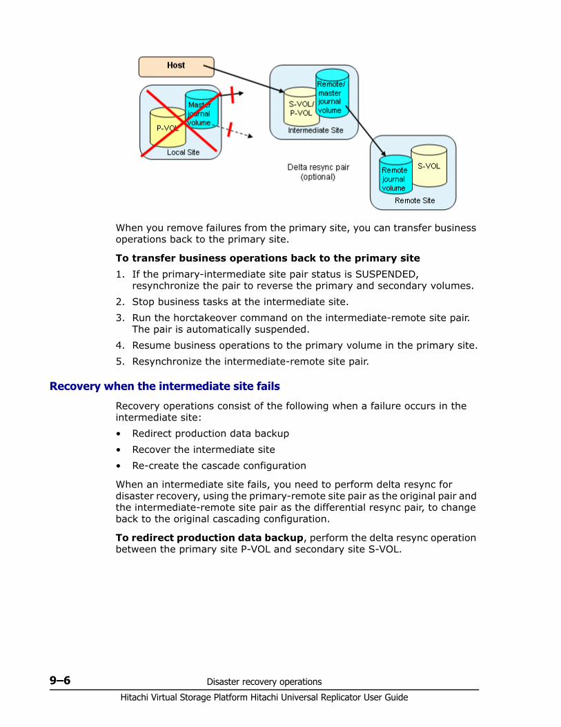
Hitachi Virtual Storage Platform Hitachi Universal Replicator User Guide
9–6 Disaster recovery operations
When you remove failures from the primary site, you can transfer business operations back to the primary site.
To transfer business operations back to the primary site1. If the primary-intermediate site pair status is SUSPENDED,
resynchronize the pair to reverse the primary and secondary volumes.2. Stop business tasks at the intermediate site.3. Run the horctakeover command on the intermediate-remote site pair.
The pair is automatically suspended.4. Resume business operations to the primary volume in the primary site.5. Resynchronize the intermediate-remote site pair.
Recovery when the intermediate site fails
Recovery operations consist of the following when a failure occurs in the intermediate site:• Redirect production data backup• Recover the intermediate site• Re-create the cascade configuration
When an intermediate site fails, you need to perform delta resync for disaster recovery, using the primary-remote site pair as the original pair and the intermediate-remote site pair as the differential resync pair, to change back to the original cascading configuration.
To redirect production data backup, perform the delta resync operation between the primary site P-VOL and secondary site S-VOL.
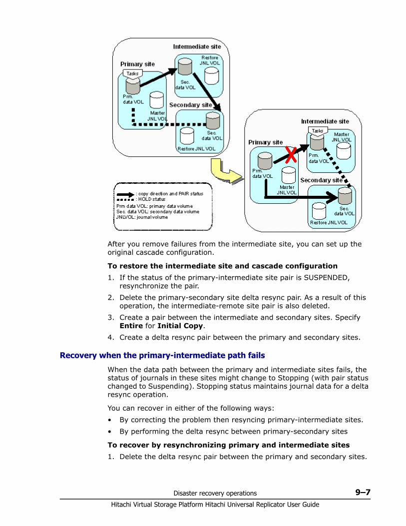
Disaster recovery operations 9–7Hitachi Virtual Storage Platform Hitachi Universal Replicator User Guide
After you remove failures from the intermediate site, you can set up the original cascade configuration.
To restore the intermediate site and cascade configuration1. If the status of the primary-intermediate site pair is SUSPENDED,
resynchronize the pair.2. Delete the primary-secondary site delta resync pair. As a result of this
operation, the intermediate-remote site pair is also deleted.3. Create a pair between the intermediate and secondary sites. Specify
Entire for Initial Copy.4. Create a delta resync pair between the primary and secondary sites.
Recovery when the primary-intermediate path fails
When the data path between the primary and intermediate sites fails, the status of journals in these sites might change to Stopping (with pair status changed to Suspending). Stopping status maintains journal data for a delta resync operation.
You can recover in either of the following ways:• By correcting the problem then resyncing primary-intermediate sites.• By performing the delta resync between primary-secondary sites
To recover by resynchronizing primary and intermediate sites1. Delete the delta resync pair between the primary and secondary sites.
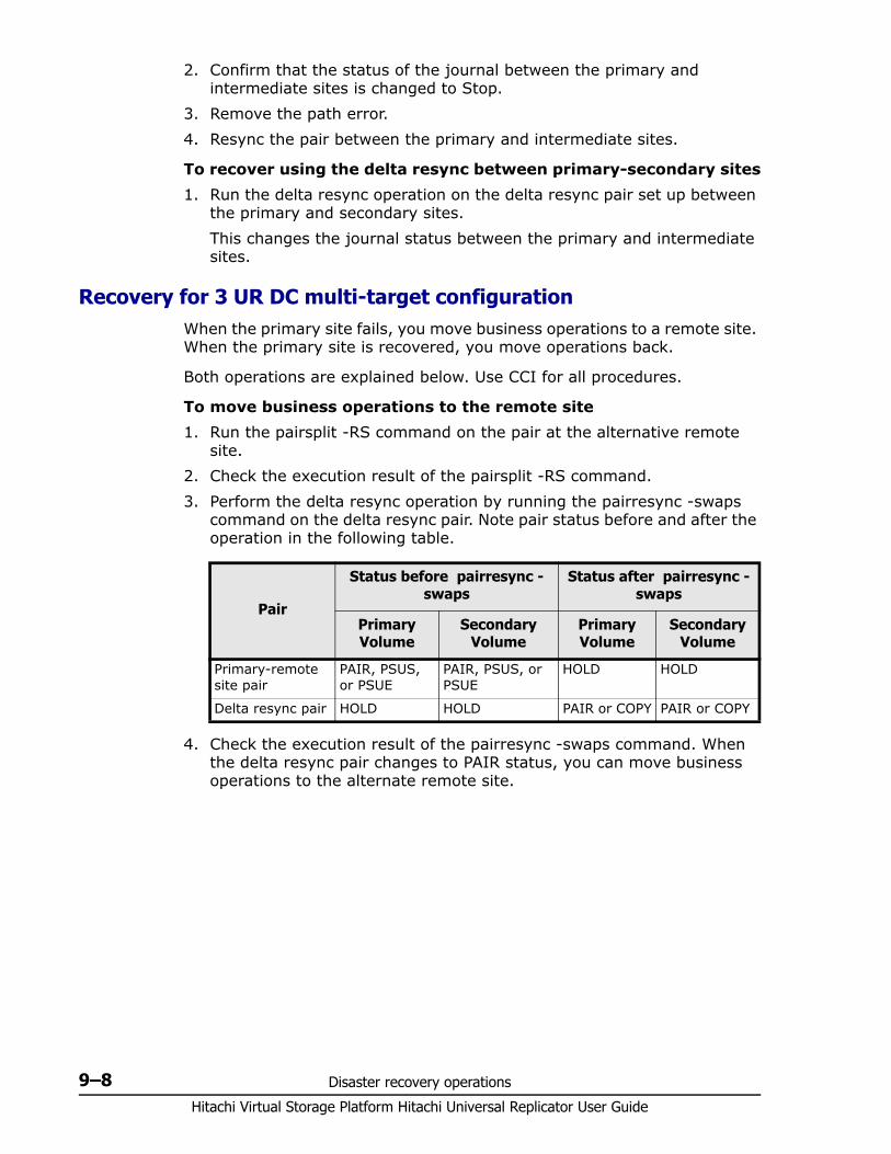
Hitachi Virtual Storage Platform Hitachi Universal Replicator User Guide
9–8 Disaster recovery operations
2. Confirm that the status of the journal between the primary and intermediate sites is changed to Stop.
3. Remove the path error. 4. Resync the pair between the primary and intermediate sites.
To recover using the delta resync between primary-secondary sites1. Run the delta resync operation on the delta resync pair set up between
the primary and secondary sites.This changes the journal status between the primary and intermediate sites.
Recovery for 3 UR DC multi-target configurationWhen the primary site fails, you move business operations to a remote site. When the primary site is recovered, you move operations back.
Both operations are explained below. Use CCI for all procedures.
To move business operations to the remote site1. Run the pairsplit -RS command on the pair at the alternative remote
site.2. Check the execution result of the pairsplit -RS command.3. Perform the delta resync operation by running the pairresync -swaps
command on the delta resync pair. Note pair status before and after the operation in the following table.
4. Check the execution result of the pairresync -swaps command. When the delta resync pair changes to PAIR status, you can move business operations to the alternate remote site.
Pair
Status before pairresync -swaps
Status after pairresync -swaps
Primary Volume
Secondary Volume
Primary Volume
Secondary Volume
Primary-remote site pair
PAIR, PSUS, or PSUE
PAIR, PSUS, or PSUE
HOLD HOLD
Delta resync pair HOLD HOLD PAIR or COPY PAIR or COPY
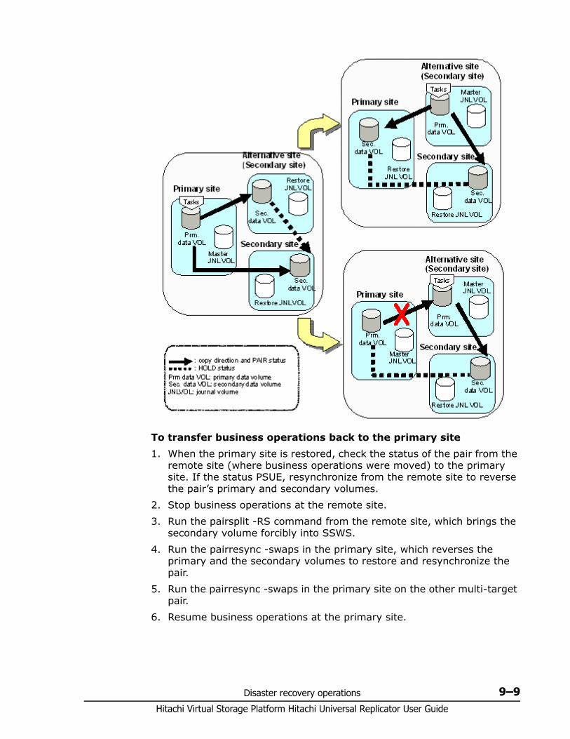
Disaster recovery operations 9–9Hitachi Virtual Storage Platform Hitachi Universal Replicator User Guide
To transfer business operations back to the primary site1. When the primary site is restored, check the status of the pair from the
remote site (where business operations were moved) to the primary site. If the status PSUE, resynchronize from the remote site to reverse the pair’s primary and secondary volumes.
2. Stop business operations at the remote site.3. Run the pairsplit -RS command from the remote site, which brings the
secondary volume forcibly into SSWS.4. Run the pairresync -swaps in the primary site, which reverses the
primary and the secondary volumes to restore and resynchronize the pair.
5. Run the pairresync -swaps in the primary site on the other multi-target pair.
6. Resume business operations at the primary site.
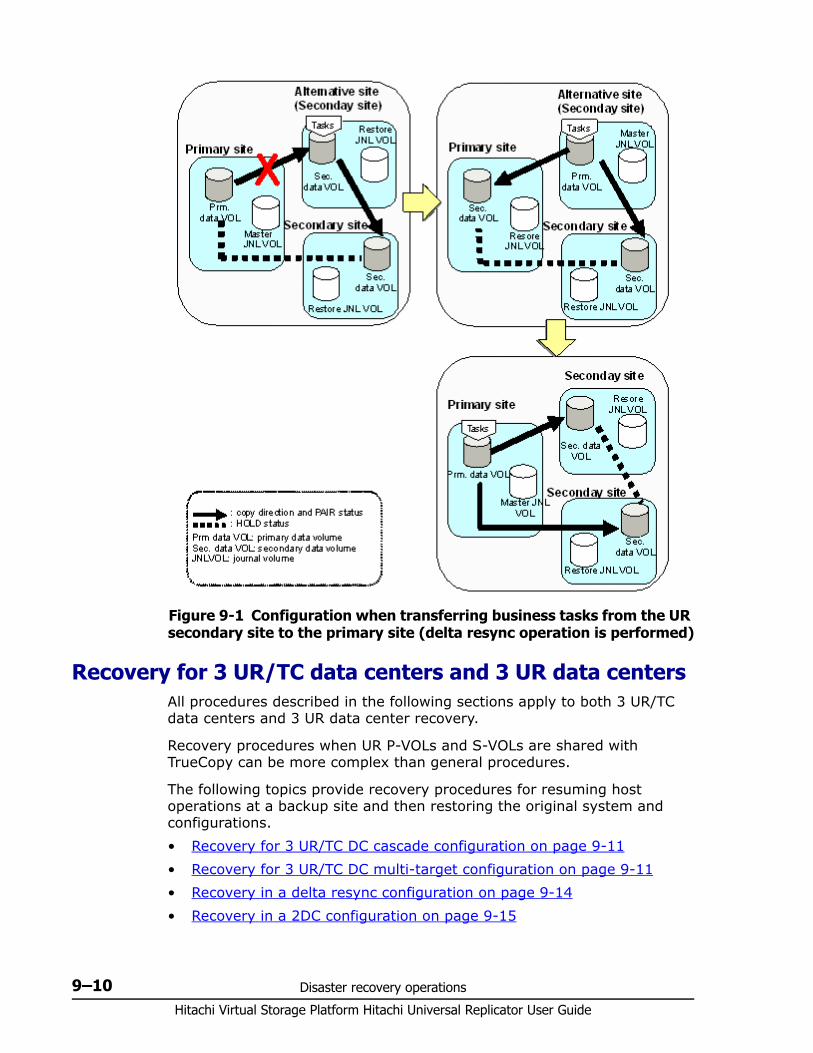
Hitachi Virtual Storage Platform Hitachi Universal Replicator User Guide
9–10 Disaster recovery operations
Recovery for 3 UR/TC data centers and 3 UR data centersAll procedures described in the following sections apply to both 3 UR/TC data centers and 3 UR data center recovery.
Recovery procedures when UR P-VOLs and S-VOLs are shared with TrueCopy can be more complex than general procedures.
The following topics provide recovery procedures for resuming host operations at a backup site and then restoring the original system and configurations.• Recovery for 3 UR/TC DC cascade configuration on page 9-11• Recovery for 3 UR/TC DC multi-target configuration on page 9-11 • Recovery in a delta resync configuration on page 9-14• Recovery in a 2DC configuration on page 9-15
Figure 9-1 Configuration when transferring business tasks from the UR secondary site to the primary site (delta resync operation is performed)
Disaster recovery operations 9–11Hitachi Virtual Storage Platform Hitachi Universal Replicator User Guide
Use CCI to perform all procedures.
Recovery for 3 UR/TC DC cascade configuration Host operations are transferred to the TC secondary volume (S-VOL) at the intermediate site when a disaster or failure occurs in the primary site of a 3DC cascade configuration. The primary site failure is corrected and brought back online, then either the cascade configuration is restored or the multi-target configuration is created.
See 3DC cascade configuration on page C-3 or 3 UR DC cascade configuration on page A-2 for information and illustrations on the configuration covered in this procedure.
To recover a 3DC cascade configuration failure 1. Check consistency of the secondary volume in the intermediate site.2. Run the horctakeover command on the secondary volume. 3. Wait until the secondary volume in the intermediate site is suspended
(in SSWS status) or changes to a primary volume, then use the volume to resume host operations.
Recovery for 3 UR/TC DC multi-target configuration The recovery procedure you perform in a 3DC multi-target configuration depends on the location of the failure:• For failure in the primary site only — see Recovering from primary site
failure on page 9-11.• For failure in the primary and TrueCopy intermediate sites — see
Recovering from primary and secondary site failure (3DC multi-target) on page 9-13
See 3DC multi-target configuration on page C-4 or 3 UR DC multi-target configuration on page A-6 for information and illustrations on the configuration covered in this procedure.
Recovering from primary site failure
For 3 UR/TC configurations, host operations are transferred to the secondary volume in the intermediate site when disaster or failure occurs in the primary site in a 3DC multi-target configuration. Replication occurs from the intermediate site to the primary site. Alternatively, a temporary UR system can be set up. Meanwhile, you correct the failure at the primary site, then transfer host operations back to it and set up a 3DC configuration.
To recover a primary site failure1. Release the UR pair.2. Run the horctakeover command on the primary-remote site pair.3. Start host operations to the remote site secondary volume.
Running the horctakeover results in one of the following conditions:
Hitachi Virtual Storage Platform Hitachi Universal Replicator User Guide
9–12 Disaster recovery operations
• The original copy flow of the primary-remote site pair reverses and flows from the primary-remote secondary volume to the primary volume.
• The original copy flow does not reverse because of failure in the primary site or data path.
Depending on the result, proceed as follows:
If the original TC data flow reverses1. Re-create the UR pair from the TC primary site to the UR remote site.
This results in a 3DC cascade configuration, with the original TC S-VOL as the primary volume. See the lower right configuration in Figure 9-2 Recovery scenarios on page 9-13.
2. Restore the primary site or data path, or both. This must be done before proceeding.
3. Stop host operations to the TC intermediate site.4. Run the horctakeover command on the TC pair.5. Resume host operations to the TC P-VOL in the primary site.
The system changes back to the original 3DC multi-target configuration.
If the original TC data flow did not reverse 1. To back up the data, create a new UR pair from the TC S-VOL in the
intermediate site to the UR secondary volume in the remote site.See the upper-right configuration in Figure 9-2 Recovery scenarios on page 9-13.
2. Restore the primary site or data path, or both. This must be done before proceeding.
3. Release the UR pair.4. Resynchronize the TC pair to start the replication to the primary site.5. Release the current UR pair, which extends between the TC secondary
site and the UR secondary site.6. Stop host operations at the TC intermediate site.7. Run the horctakeover command on the TC pair.8. Resume host operations to the primary site TC volume.9. Re-create the UR pair from the primary site to the remote site. The
system is now changed back to the original 3DC multi-target configuration.
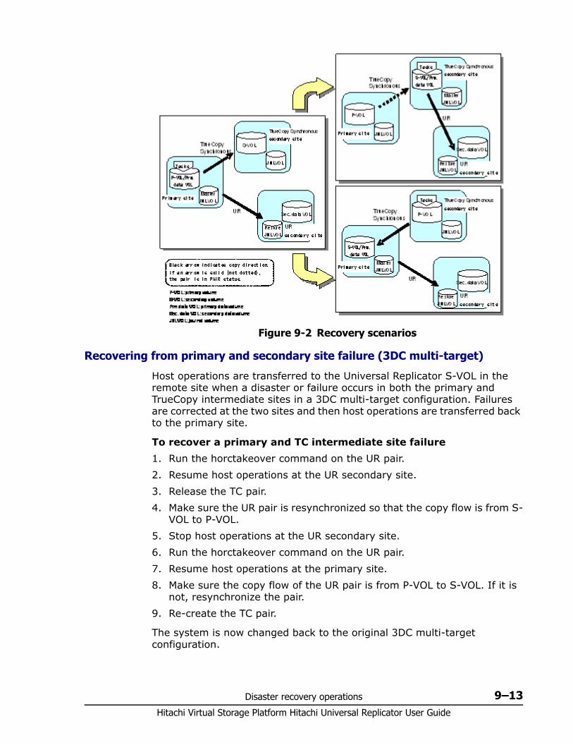
Disaster recovery operations 9–13Hitachi Virtual Storage Platform Hitachi Universal Replicator User Guide
Recovering from primary and secondary site failure (3DC multi-target)
Host operations are transferred to the Universal Replicator S-VOL in the remote site when a disaster or failure occurs in both the primary and TrueCopy intermediate sites in a 3DC multi-target configuration. Failures are corrected at the two sites and then host operations are transferred back to the primary site.
To recover a primary and TC intermediate site failure 1. Run the horctakeover command on the UR pair.2. Resume host operations at the UR secondary site.3. Release the TC pair.4. Make sure the UR pair is resynchronized so that the copy flow is from S-
VOL to P-VOL.5. Stop host operations at the UR secondary site.6. Run the horctakeover command on the UR pair.7. Resume host operations at the primary site.8. Make sure the copy flow of the UR pair is from P-VOL to S-VOL. If it is
not, resynchronize the pair.9. Re-create the TC pair.
The system is now changed back to the original 3DC multi-target configuration.
Figure 9-2 Recovery scenarios
Hitachi Virtual Storage Platform Hitachi Universal Replicator User Guide
9–14 Disaster recovery operations
Recovery in a delta resync configurationHost operations are transferred to the TrueCopy S-VOL in the intermediate site when a disaster or failure occurs in the primary site in a delta resync configuration. Then you run the delta resync operation. When the failure at the primary site is corrected, host operations are transferred back to the primary site and the delta resync configuration is reestablished.
Prerequisite information• For information and illustrations on the configuration covered in this
procedure, see Delta resync configuration on page C-6.• You can specify options for recovery in the event that the delta resync
operation fails. See the Delta resync Failure step in Changing options used by mirrors on page 8-5. This also provides important information if you share the delta resync S-VOL with ShadowImage, Thin Image, or Copy-on-Write Snapshot and a DP-VOL.
To recover a delta resync configuration failure1. Run the horctakeover command on the TC pair.2. Start host operations to the TC S-VOL.3. Perform the delta resync operation on the volume in the TC intermediate
site. See Prerequisite information for delta resync operation on page C-9. Note that pair status must be HOLD before the operation. When the operation completes, pair status is PAIR or COPY.
4. Restore the problem at the primary site. This must be done before proceeding.
5. If the TC pair is suspended, resynchronize the pair and reverse the copy flow.
6. Stop host operations to the TC intermediate site.7. Run the horctakeover command on the TC pair.8. Resume host operations to the TC P-VOL in the primary site.9. Perform the delta resync operation on the volume in the TC primary site.
Pair status must be HOLD. When the operation completes, pair status is PAIR or COPY.Also, pair status changes for the delta resync UR pair from the TC intermediate to the UR remote site, from PAIR, PSUS, or PSUE to HOLD.
The system becomes a delta resync configuration again.
Note: Pair status also changes for the original UR pair in the primary and UR remote sites, from PAIR or COPY to HOLD.
However, the status of the original pair may not change to the required state after the delta resync operation. If this occurs, host operations cannot be resumed in the primary site. See Problems with pair status during delta resync recovery on page 9-15 and make the necessary corrections.
Disaster recovery operations 9–15Hitachi Virtual Storage Platform Hitachi Universal Replicator User Guide
Problems with pair status during delta resync recovery
After performing the delta resync, it is necessary for the original UR pair from the primary to UR remote sites to be in HOLD status, in order to resume operations at the primary site. However, the pair may not be in this status.
If pair status is not HOLD, match the pair’s actual statuses in the following table and then perform the corrective action.
Recovery in a 2DC configuration Host operations are transferred to the Universal Replicator S-VOL in the remote site when a disaster or failure occurs in the primary site in a 2DC configuration. Failures are corrected at the primary site, host operations are transferred back, and the 2DC configuration is reestablished.
See 2 data center configuration on page C-15 for information and illustrations on the configuration covered in this procedure.
To recover a 2DC configuration failure1. In the remote site, confirm the consistency of the UR S-VOL.2. In the intermediate site, release the TC pair using the Pairsplit-S
command.3. In the intermediate and remote sites, release the UR pair using the
Pairsplit-S command.4. Confirm that the UR S-VOL has changed to SMPL status.
Current status Corrective action
Primary site: PAIR or COPYUR secondary site: HOLD
1. Make sure that the status of the pair in the primary site is PSUE or PSUS.
2. Release the UR pair from the primary site.3. Make sure that all the pairs belonging to the journal
in the primary site are released.4. Create a UR delta resync pair that extends from the
primary site to the UR secondary site.
Primary site: PSUE or PSUSUR secondary site: HOLD
1. Release the UR pair from the primary site.2. Make sure that all the pairs belonging to the journal
in the primary site are released.3. Create a UR delta resync pair that extends from the
primary site to the UR secondary site.
Primary site: HLDEUR secondary site: HOLD
Change the status of the HLDE pair back to HOLD using pairresync.
Primary site: SMPLUR secondary site: HOLD
1. Release the pair in HOLD status from the UR secondary site.
2. Create a UR delta resync pair that extends from the primary site to the UR secondary site.
Hitachi Virtual Storage Platform Hitachi Universal Replicator User Guide
9–16 Disaster recovery operations
5. Resume host operations to the UR S-VOL on the remote site.
6. On the primary site, if TC pairs exist, release them.7. On the remote UR site, create a TC pair:
Use the UR S-VOL on the remote site as the TC P-VOL. This is the current disaster recovery production volume.
Use the primary site volume as the TC S-VOLFollow all requirements for creating a TC pair.
8. After the new TC pair is in PAIR status, stop host operations at the remote site, then release the TC pair.
9. On the intermediate site, create a UR pair to the UR remote site, with no data copying (specify None on the Copy Mode option). Specify the intermediate site volume as the UR P-VOL and the remote volume as the UR S-VOL.
10.On the primary site, create a TC pair between the primary site data volume and the intermediate site UR P-VOL, with no data copying. When this is done, since host operations have not resumed, all three sites have the same data in their respective volumes.
11.Resume host operations at the primary site. Synchronous copying will resume between the primary site TC P-VOL and the intermediate site S-VOL. UR copying will resume from intermediate site to remote site.
The system becomes a 2DC configuration again.
Recovery for configurations with UR/ShadowImageSee Configurations with ShadowImage secondary volumes on page D-4 for information and illustrations on the configuration covered in this procedure.
You resume host operations to the remote Universal Replicator secondary volume if a disaster or failure occurs at the primary site where the UR P-VOL is shared with the ShadowImage (SI) secondary volume. Then you recover the primary site and then resume host operations.
To recover from failure in a UR P-VOL/SI S-VOL configuration1. Release the SI pair using the pairsplit -S command.2. Reverse the copy direction and resync the UR pair using the
horctakeover command.3. Reverse the copy direction again on the UR pair using the horctakeover
command.4. Delete the UR pair using the pairsplit -S command.
Note: Be aware of the following:• The 2DC configuration does not allow host operations on the
intermediate site.• If the intermediate site is not connected to a host, use the remote
command device for UR and TC pair operations.
Disaster recovery operations 9–17Hitachi Virtual Storage Platform Hitachi Universal Replicator User Guide
5. Create a SI pair from the SI S-VOL to perform copying in the reverse direction. Use the paircreate command.
6. Release the SI pair using the pairsplit -S command.7. Re-create the original SI pair from the original SI P-VOL to perform
copying in the original direction. Use the paircreate command.8. Split the SI pair using the pairsplit -r command.9. Recreate the UR pair using the paircreate command.
The system becomes the original configuration again.

Hitachi Virtual Storage Platform Hitachi Universal Replicator User Guide
9–18 Disaster recovery operations

10
Troubleshooting 10–1Hitachi Virtual Storage Platform Hitachi Universal Replicator User Guide
Troubleshooting
This chapter provides Universal Replicator troubleshooting information.
□ General troubleshooting
□ Troubleshooting logical paths
□ Troubleshooting by suspension type
□ Troubleshooting hardware problems affecting pairs
□ Troubleshooting with CCI
□ Service information messages (SIMs)
□ Miscellaneous troubleshooting
□ Calling the Hitachi Data Systems Support Center
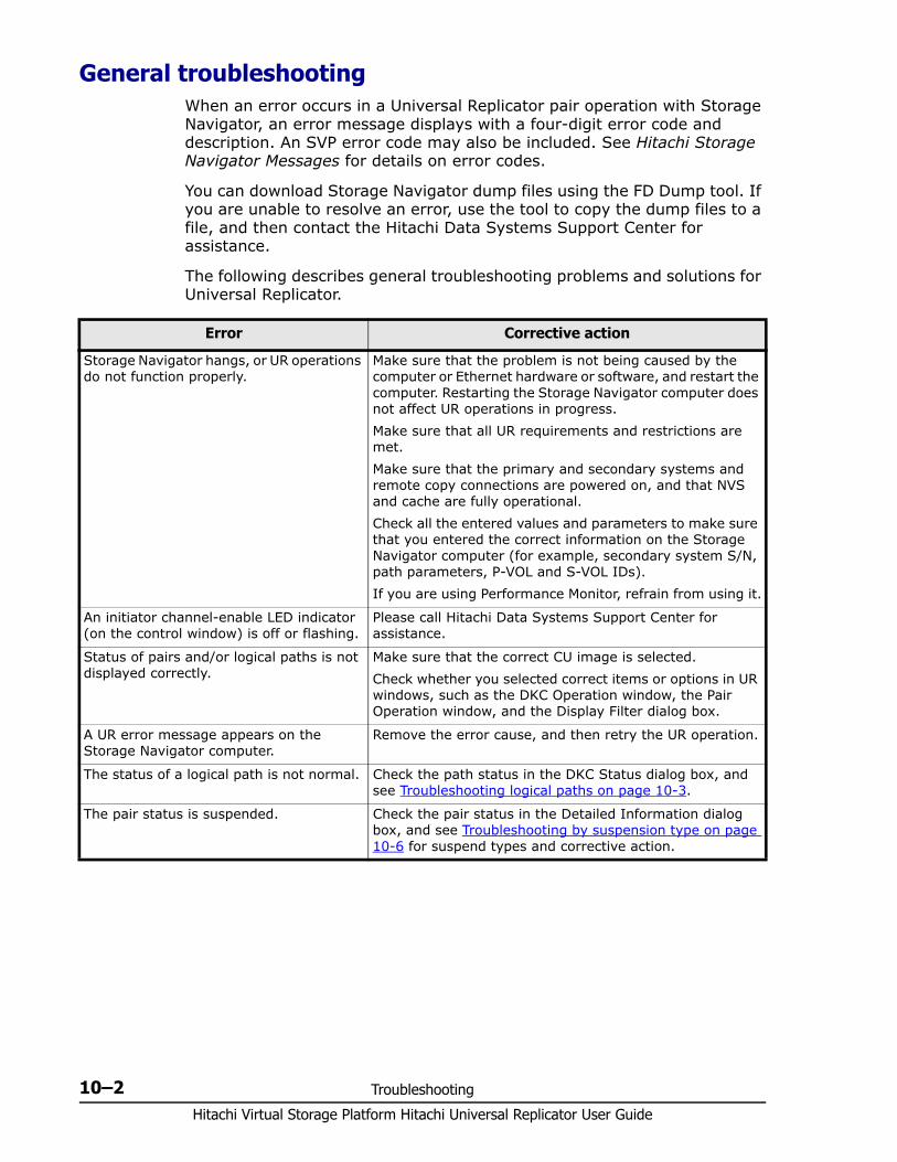
Hitachi Virtual Storage Platform Hitachi Universal Replicator User Guide
10–2 Troubleshooting
General troubleshootingWhen an error occurs in a Universal Replicator pair operation with Storage Navigator, an error message displays with a four-digit error code and description. An SVP error code may also be included. See Hitachi Storage Navigator Messages for details on error codes.
You can download Storage Navigator dump files using the FD Dump tool. If you are unable to resolve an error, use the tool to copy the dump files to a file, and then contact the Hitachi Data Systems Support Center for assistance.
The following describes general troubleshooting problems and solutions for Universal Replicator.
Error Corrective action
Storage Navigator hangs, or UR operations do not function properly.
Make sure that the problem is not being caused by the computer or Ethernet hardware or software, and restart the computer. Restarting the Storage Navigator computer does not affect UR operations in progress.Make sure that all UR requirements and restrictions are met.Make sure that the primary and secondary systems and remote copy connections are powered on, and that NVS and cache are fully operational.Check all the entered values and parameters to make sure that you entered the correct information on the Storage Navigator computer (for example, secondary system S/N, path parameters, P-VOL and S-VOL IDs). If you are using Performance Monitor, refrain from using it.
An initiator channel-enable LED indicator (on the control window) is off or flashing.
Please call Hitachi Data Systems Support Center for assistance.
Status of pairs and/or logical paths is not displayed correctly.
Make sure that the correct CU image is selected.Check whether you selected correct items or options in UR windows, such as the DKC Operation window, the Pair Operation window, and the Display Filter dialog box.
A UR error message appears on the Storage Navigator computer.
Remove the error cause, and then retry the UR operation.
The status of a logical path is not normal. Check the path status in the DKC Status dialog box, and see Troubleshooting logical paths on page 10-3.
The pair status is suspended. Check the pair status in the Detailed Information dialog box, and see Troubleshooting by suspension type on page 10-6 for suspend types and corrective action.
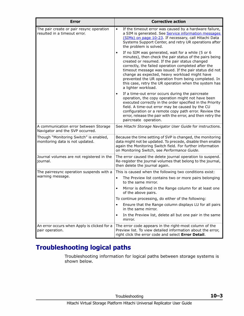
Troubleshooting 10–3Hitachi Virtual Storage Platform Hitachi Universal Replicator User Guide
Troubleshooting logical paths Troubleshooting information for logical paths between storage systems is shown below.
The pair create or pair resync operation resulted in a timeout error.
• If the timeout error was caused by a hardware failure, a SIM is generated. See Service information messages (SIMs) on page 10-23. If necessary, call Hitachi Data Systems Support Center, and retry UR operations after the problem is solved.
• If no SIM was generated, wait for a while (5 or 6 minutes), then check the pair status of the pairs being created or resumed. If the pair status changed correctly, the failed operation completed after the timeout message was issued. If the pair status did not change as expected, heavy workload might have prevented the UR operation from being completed. In this case, retry the UR operation when the system has a lighter workload.
• If a time-out error occurs during the paircreate operation, the copy operation might not have been executed correctly in the order specified in the Priority field. A time-out error may be caused by the CU configuration or a remote copy path error. Review the error, release the pair with the error, and then retry the paircreate operation.
A communication error between Storage Navigator and the SVP occurred.
See Hitachi Storage Navigator User Guide for instructions.
Though “Monitoring Switch” is enabled, monitoring data is not updated.
Because the time setting of SVP is changed, the monitoring data might not be updated. To precede, disable then enable again the Monitoring Switch field. For further information on Monitoring Switch, see Performance Guide.
Journal volumes are not registered in the journal.
The error caused the delete journal operation to suspend. Re-register the journal volumes that belong to the journal, then delete the journal again.
The pairresync operation suspends with a warning message.
This is caused when the following two conditions exist:• The Preview list contains two or more pairs belonging
to the same mirror.• Mirror is defined in the Range column for at least one
of the above pairs.To continue processing, do either of the following:• Ensure that the Range column displays LU for all pairs
in the same mirror.• In the Preview list, delete all but one pair in the same
mirror.
An error occurs when Apply is clicked for a pair operation.
The error code appears in the right-most column of the Preview list. To view detailed information about the error, right click the error code and select Error Detail.
Error Corrective action
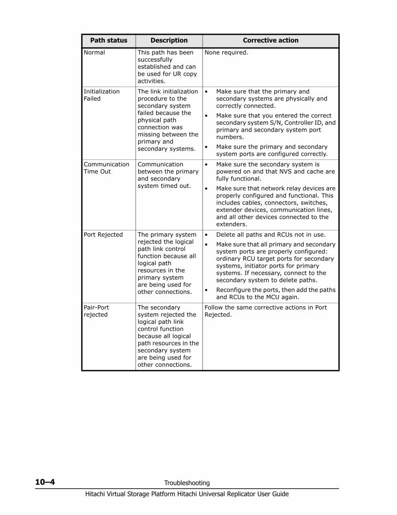
Hitachi Virtual Storage Platform Hitachi Universal Replicator User Guide
10–4 Troubleshooting
Path status Description Corrective action
Normal This path has been successfully established and can be used for UR copy activities.
None required.
Initialization Failed
The link initialization procedure to the secondary system failed because the physical path connection was missing between the primary and secondary systems.
• Make sure that the primary and secondary systems are physically and correctly connected.
• Make sure that you entered the correct secondary system S/N, Controller ID, and primary and secondary system port numbers.
• Make sure the primary and secondary system ports are configured correctly.
Communication Time Out
Communication between the primary and secondary system timed out.
• Make sure the secondary system is powered on and that NVS and cache are fully functional.
• Make sure that network relay devices are properly configured and functional. This includes cables, connectors, switches, extender devices, communication lines, and all other devices connected to the extenders.
Port Rejected The primary system rejected the logical path link control function because all logical path resources in the primary system are being used for other connections.
• Delete all paths and RCUs not in use.• Make sure that all primary and secondary
system ports are properly configured: ordinary RCU target ports for secondary systems, initiator ports for primary systems. If necessary, connect to the secondary system to delete paths.
• Reconfigure the ports, then add the paths and RCUs to the MCU again.
Pair-Port rejected
The secondary system rejected the logical path link control function because all logical path resources in the secondary system are being used for other connections.
Follow the same corrective actions in Port Rejected.
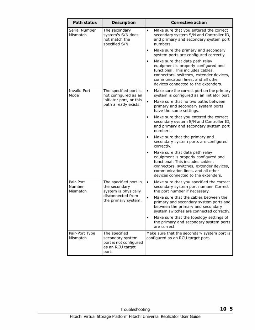
Troubleshooting 10–5Hitachi Virtual Storage Platform Hitachi Universal Replicator User Guide
Serial Number Mismatch
The secondary system's S/N does not match the specified S/N.
• Make sure that you entered the correct secondary system S/N and Controller ID, and primary and secondary system port numbers.
• Make sure the primary and secondary system ports are configured correctly.
• Make sure that data path relay equipment is properly configured and functional. This includes cables, connectors, switches, extender devices, communication lines, and all other devices connected to the extenders.
Invalid Port Mode
The specified port is not configured as an initiator port, or this path already exists.
• Make sure the correct port on the primary system is configured as an initiator port.
• Make sure that no two paths between primary and secondary system ports have the same settings.
• Make sure that you entered the correct secondary system S/N and Controller ID, and primary and secondary system port numbers.
• Make sure that the primary and secondary system ports are configured correctly.
• Make sure that data path relay equipment is properly configured and functional. This includes cables, connectors, switches, extender devices, communication lines, and all other devices connected to the extenders.
Pair-Port Number Mismatch
The specified port in the secondary system is physically disconnected from the primary system.
• Make sure that you specified the correct secondary system port number. Correct the port number if necessary.
• Make sure that the cables between the primary and secondary system ports and between the primary and secondary system switches are connected correctly.
• Make sure that the topology settings of the primary and secondary system ports are correct.
Pair-Port Type Mismatch
The specified secondary system port is not configured as an RCU target port.
Make sure that the secondary system port is configured as an RCU target port.
Path status Description Corrective action
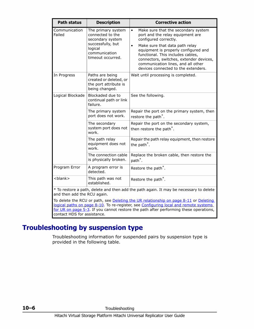
Hitachi Virtual Storage Platform Hitachi Universal Replicator User Guide
10–6 Troubleshooting
Troubleshooting by suspension type Troubleshooting information for suspended pairs by suspension type is provided in the following table.
Communication Failed
The primary system connected to the secondary system successfully, but logical communication timeout occurred.
• Make sure that the secondary system port and the relay equipment are configured correctly.
• Make sure that data path relay equipment is properly configured and functional. This includes cables, connectors, switches, extender devices, communication lines, and all other devices connected to the extenders.
In Progress Paths are being created or deleted, or the port attribute is being changed.
Wait until processing is completed.
Logical Blockade Blockaded due to continual path or link failure.
See the following.
The primary system port does not work.
Repair the port on the primary system, then restore the path*.
The secondary system port does not work.
Repair the port on the secondary system, then restore the path*.
The path relay equipment does not work.
Repair the path relay equipment, then restore the path*.
The connection cable is physically broken.
Replace the broken cable, then restore the path*.
Program Error A program error is detected.
Restore the path*.
<blank> This path was not established.
Restore the path*.
* To restore a path, delete and then add the path again. It may be necessary to delete and then add the RCU again. To delete the RCU or path, see Deleting the UR relationship on page 8-11 or Deleting logical paths on page 8-10. To re-register, see Configuring local and remote systems for UR on page 5-3. If you cannot restore the path after performing these operations, contact HDS for assistance.
Path status Description Corrective action
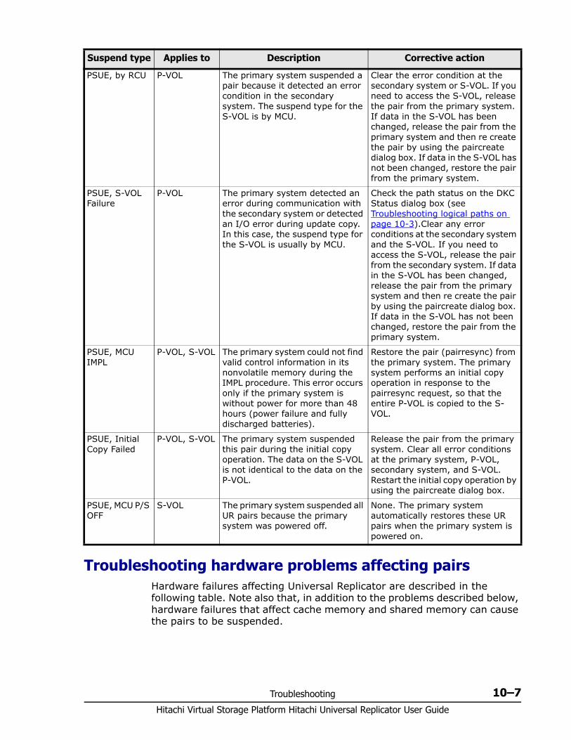
Troubleshooting 10–7Hitachi Virtual Storage Platform Hitachi Universal Replicator User Guide
Troubleshooting hardware problems affecting pairsHardware failures affecting Universal Replicator are described in the following table. Note also that, in addition to the problems described below, hardware failures that affect cache memory and shared memory can cause the pairs to be suspended.
Suspend type Applies to Description Corrective action
PSUE, by RCU P-VOL The primary system suspended a pair because it detected an error condition in the secondary system. The suspend type for the S-VOL is by MCU.
Clear the error condition at the secondary system or S-VOL. If you need to access the S-VOL, release the pair from the primary system. If data in the S-VOL has been changed, release the pair from the primary system and then re create the pair by using the paircreate dialog box. If data in the S-VOL has not been changed, restore the pair from the primary system.
PSUE, S-VOL Failure
P-VOL The primary system detected an error during communication with the secondary system or detected an I/O error during update copy. In this case, the suspend type for the S-VOL is usually by MCU.
Check the path status on the DKC Status dialog box (see Troubleshooting logical paths on page 10-3).Clear any error conditions at the secondary system and the S-VOL. If you need to access the S-VOL, release the pair from the secondary system. If data in the S-VOL has been changed, release the pair from the primary system and then re create the pair by using the paircreate dialog box. If data in the S-VOL has not been changed, restore the pair from the primary system.
PSUE, MCU IMPL
P-VOL, S-VOL The primary system could not find valid control information in its nonvolatile memory during the IMPL procedure. This error occurs only if the primary system is without power for more than 48 hours (power failure and fully discharged batteries).
Restore the pair (pairresync) from the primary system. The primary system performs an initial copy operation in response to the pairresync request, so that the entire P-VOL is copied to the S-VOL.
PSUE, Initial Copy Failed
P-VOL, S-VOL The primary system suspended this pair during the initial copy operation. The data on the S-VOL is not identical to the data on the P-VOL.
Release the pair from the primary system. Clear all error conditions at the primary system, P-VOL, secondary system, and S-VOL. Restart the initial copy operation by using the paircreate dialog box.
PSUE, MCU P/S OFF
S-VOL The primary system suspended all UR pairs because the primary system was powered off.
None. The primary system automatically restores these UR pairs when the primary system is powered on.
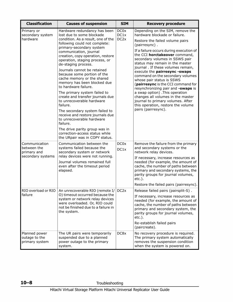
Hitachi Virtual Storage Platform Hitachi Universal Replicator User Guide
10–8 Troubleshooting
Classification Causes of suspension SIM Recovery procedure
Primary or secondary system hardware
Hardware redundancy has been lost due to some blockade condition. As a result, one of the following could not complete: primary-secondary system communication, journal creation, copy operation, restore operation, staging process, or de-staging process.Journals cannot be retained because some portion of the cache memory or the shared memory has been blocked due to hardware failure.The primary system failed to create and transfer journals due to unrecoverable hardware failure.The secondary system failed to receive and restore journals due to unrecoverable hardware failure.The drive parity group was in correction-access status while the URpair was in COPY status.
DC0x DC1x DC2x
Depending on the SIM, remove the hardware blockade or failure.Restore the failed volume pairs (pairresync) .If a failure occurs during execution of the CCI horctakeover command, secondary volumes in SSWS pair status may remain in the master journal . If these volumes remain, execute the pairresync -swaps command on the secondary volumes whose pair status is SSWS (pairresync is the CCI command for resynchronizing pair and -swaps is a swap option) .This operation changes all volumes in the master journal to primary volumes. After this operation, restore the volume pairs (pairresync).
Communication between the primary and secondary systems
Communication between the systems failed because the secondary system or network relay devices were not running.Journal volumes remained full even after the timeout period elapsed.
DC0xDC1x
Remove the failure from the primary and secondary systems or the network relay devices.If necessary, increase resources as needed (for example, the amount of cache, the number of paths between primary and secondary systems, the parity groups for journal volumes, etc.).Restore the failed pairs (pairresync).
RIO overload or RIO failure
An unrecoverable RIO (remote I/O) timeout occurred because the system or network relay devices were overloaded. Or, RIO could not be finished due to a failure in the system.
DC2x Release failed pairs (pairsplit-S) .If necessary, increase resources as needed (for example, the amount of cache, the number of paths between primary and secondary system, the parity groups for journal volumes, etc.).Re-establish failed pairs (paircreate).
Planned power outage to the primary system
The UR pairs were temporarily suspended due to a planned power outage to the primary system.
DC8x No recovery procedure is required. The primary system automatically removes the suspension condition when the system is powered on.
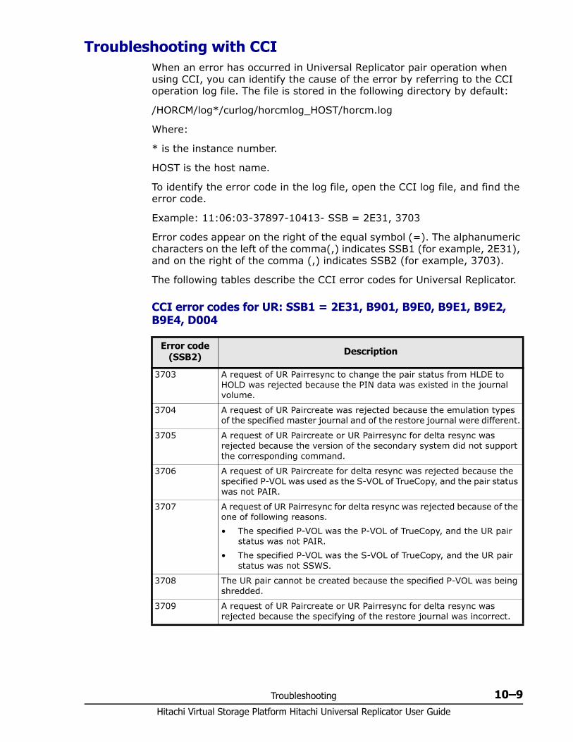
Troubleshooting 10–9Hitachi Virtual Storage Platform Hitachi Universal Replicator User Guide
Troubleshooting with CCI When an error has occurred in Universal Replicator pair operation when using CCI, you can identify the cause of the error by referring to the CCI operation log file. The file is stored in the following directory by default:
/HORCM/log*/curlog/horcmlog_HOST/horcm.log
Where:
* is the instance number.
HOST is the host name.
To identify the error code in the log file, open the CCI log file, and find the error code.
Example: 11:06:03-37897-10413- SSB = 2E31, 3703
Error codes appear on the right of the equal symbol (=). The alphanumeric characters on the left of the comma(,) indicates SSB1 (for example, 2E31), and on the right of the comma (,) indicates SSB2 (for example, 3703).
The following tables describe the CCI error codes for Universal Replicator.
CCI error codes for UR: SSB1 = 2E31, B901, B9E0, B9E1, B9E2, B9E4, D004
Error code (SSB2) Description
3703 A request of UR Pairresync to change the pair status from HLDE to HOLD was rejected because the PIN data was existed in the journal volume.
3704 A request of UR Paircreate was rejected because the emulation types of the specified master journal and of the restore journal were different.
3705 A request of UR Paircreate or UR Pairresync for delta resync was rejected because the version of the secondary system did not support the corresponding command.
3706 A request of UR Paircreate for delta resync was rejected because the specified P-VOL was used as the S-VOL of TrueCopy, and the pair status was not PAIR.
3707 A request of UR Pairresync for delta resync was rejected because of the one of following reasons.• The specified P-VOL was the P-VOL of TrueCopy, and the UR pair
status was not PAIR.• The specified P-VOL was the S-VOL of TrueCopy, and the UR pair
status was not SSWS.
3708 The UR pair cannot be created because the specified P-VOL was being shredded.
3709 A request of UR Paircreate or UR Pairresync for delta resync was rejected because the specifying of the restore journal was incorrect.
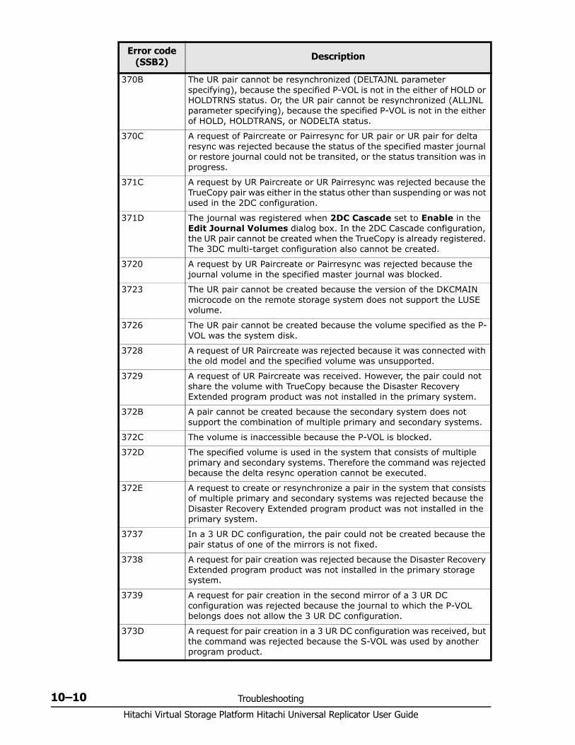
Hitachi Virtual Storage Platform Hitachi Universal Replicator User Guide
10–10 Troubleshooting
370B The UR pair cannot be resynchronized (DELTAJNL parameter specifying), because the specified P-VOL is not in the either of HOLD or HOLDTRNS status. Or, the UR pair cannot be resynchronized (ALLJNL parameter specifying), because the specified P-VOL is not in the either of HOLD, HOLDTRANS, or NODELTA status.
370C A request of Paircreate or Pairresync for UR pair or UR pair for delta resync was rejected because the status of the specified master journal or restore journal could not be transited, or the status transition was in progress.
371C A request by UR Paircreate or UR Pairresync was rejected because the TrueCopy pair was either in the status other than suspending or was not used in the 2DC configuration.
371D The journal was registered when 2DC Cascade set to Enable in the Edit Journal Volumes dialog box. In the 2DC Cascade configuration, the UR pair cannot be created when the TrueCopy is already registered. The 3DC multi-target configuration also cannot be created.
3720 A request by UR Paircreate or Pairresync was rejected because the journal volume in the specified master journal was blocked.
3723 The UR pair cannot be created because the version of the DKCMAIN microcode on the remote storage system does not support the LUSE volume.
3726 The UR pair cannot be created because the volume specified as the P-VOL was the system disk.
3728 A request of UR Paircreate was rejected because it was connected with the old model and the specified volume was unsupported.
3729 A request of UR Paircreate was received. However, the pair could not share the volume with TrueCopy because the Disaster Recovery Extended program product was not installed in the primary system.
372B A pair cannot be created because the secondary system does not support the combination of multiple primary and secondary systems.
372C The volume is inaccessible because the P-VOL is blocked.
372D The specified volume is used in the system that consists of multiple primary and secondary systems. Therefore the command was rejected because the delta resync operation cannot be executed.
372E A request to create or resynchronize a pair in the system that consists of multiple primary and secondary systems was rejected because the Disaster Recovery Extended program product was not installed in the primary system.
3737 In a 3 UR DC configuration, the pair could not be created because the pair status of one of the mirrors is not fixed.
3738 A request for pair creation was rejected because the Disaster Recovery Extended program product was not installed in the primary storage system.
3739 A request for pair creation in the second mirror of a 3 UR DC configuration was rejected because the journal to which the P-VOL belongs does not allow the 3 UR DC configuration.
373D A request for pair creation in a 3 UR DC configuration was received, but the command was rejected because the S-VOL was used by another program product.
Error code (SSB2) Description
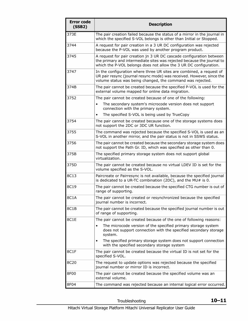
Troubleshooting 10–11Hitachi Virtual Storage Platform Hitachi Universal Replicator User Guide
373E The pair creation failed because the status of a mirror in the journal in which the specified S-VOL belongs is other than Initial or Stopped.
3744 A request for pair creation in a 3 UR DC configuration was rejected because the P-VOL was used by another program product.
3745 A request for pair creation jn 3 UR DC cascade configuration between the primary and intermediate sites was rejected because the journal to which the P-VOL belongs does not allow the 3 UR DC configuration.
3747 In the configuration where three UR sites are combined, a request of UR pair resync (journal resync mode) was received. However, since the volume status was being changed, the command was rejected.
374B The pair cannot be created because the specified P-VOL is used for the external volume mapped for online data migration.
3752 The pair cannot be created because of one of the following:• The secondary system's microcode version does not support
connection with the primary system.• The specified S-VOL is being used by TrueCopy
3754 The pair cannot be created because one of the storage systems does not support the 2DC or 3DC UR function.
3755 The command was rejected because the specified S-VOL is used as an S-VOL in another mirror, and the pair status is not in SSWS status.
3756 The pair cannot be created because the secondary storage system does not support the Path Gr. ID, which was specified as other than 0.
375B The specified primary storage system does not support global virtualization.
375D The pair cannot be created because no virtual LDEV ID is set for the volume specified as the S-VOL.
8C13 Paircreate or Pairresync is not available, because the specified journal is dedicated to a UR-TC combination (2DC), and the MU# is 0.
8C19 The pair cannot be created because the specified CTG number is out of range of supporting.
8C1A The pair cannot be created or resynchronized because the specified journal number is incorrect.
8C1B The pair cannot be created because the specified journal number is out of range of supporting.
8C1E The pair cannot be created because of the one of following reasons:• The microcode version of the specified primary storage system
does not support connection with the specified secondary storage system.
• The specified primary storage system does not support connection with the specified secondary storage system
8C1F The pair cannot be created because the virtual ID is not set for the specified S-VOL.
8C20 The request to update options was rejected because the specified journal number or mirror ID is incorrect.
8F00 The pair cannot be created because the specified volume was an external volume.
8F04 The command was rejected because an internal logical error occurred.
Error code (SSB2) Description
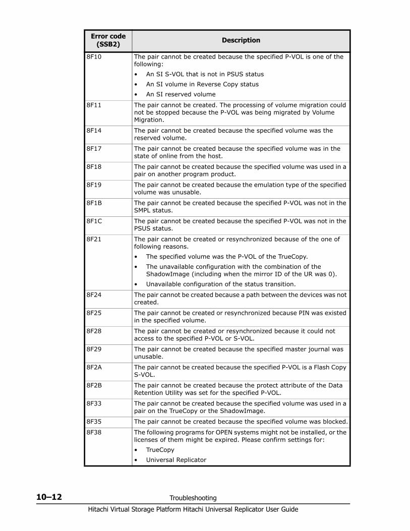
Hitachi Virtual Storage Platform Hitachi Universal Replicator User Guide
10–12 Troubleshooting
8F10 The pair cannot be created because the specified P-VOL is one of the following:• An SI S-VOL that is not in PSUS status• An SI volume in Reverse Copy status• An SI reserved volume
8F11 The pair cannot be created. The processing of volume migration could not be stopped because the P-VOL was being migrated by Volume Migration.
8F14 The pair cannot be created because the specified volume was the reserved volume.
8F17 The pair cannot be created because the specified volume was in the state of online from the host.
8F18 The pair cannot be created because the specified volume was used in a pair on another program product.
8F19 The pair cannot be created because the emulation type of the specified volume was unusable.
8F1B The pair cannot be created because the specified P-VOL was not in the SMPL status.
8F1C The pair cannot be created because the specified P-VOL was not in the PSUS status.
8F21 The pair cannot be created or resynchronized because of the one of following reasons.• The specified volume was the P-VOL of the TrueCopy.• The unavailable configuration with the combination of the
ShadowImage (including when the mirror ID of the UR was 0).• Unavailable configuration of the status transition.
8F24 The pair cannot be created because a path between the devices was not created.
8F25 The pair cannot be created or resynchronized because PIN was existed in the specified volume.
8F28 The pair cannot be created or resynchronized because it could not access to the specified P-VOL or S-VOL.
8F29 The pair cannot be created because the specified master journal was unusable.
8F2A The pair cannot be created because the specified P-VOL is a Flash Copy S-VOL.
8F2B The pair cannot be created because the protect attribute of the Data Retention Utility was set for the specified P-VOL.
8F33 The pair cannot be created because the specified volume was used in a pair on the TrueCopy or the ShadowImage.
8F35 The pair cannot be created because the specified volume was blocked.
8F38 The following programs for OPEN systems might not be installed, or the licenses of them might be expired. Please confirm settings for:• TrueCopy• Universal Replicator
Error code (SSB2) Description
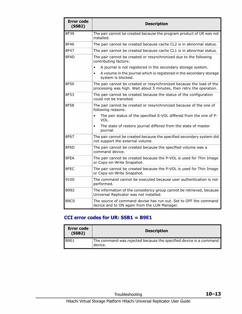
Troubleshooting 10–13Hitachi Virtual Storage Platform Hitachi Universal Replicator User Guide
CCI error codes for UR: SSB1 = B9E1
8F39 The pair cannot be created because the program product of UR was not installed.
8F46 The pair cannot be created because cache CL2 is in abnormal status.
8F47 The pair cannot be created because cache CL1 is in abnormal status.
8F4D The pair cannot be created or resynchronized due to the following contributing factors:• A journal is not registered in the secondary storage system.• A volume in the journal which is registered in the secondary storage
system is blocked.
8F50 The pair cannot be created or resynchronized because the load of the processing was high. Wait about 5 minutes, then retry the operation.
8F53 The pair cannot be created because the status of the configuration could not be transited.
8F58 The pair cannot be created or resynchronized because of the one of following reasons.• The pair status of the specified S-VOL differed from the one of P-
VOL.• The state of restore journal differed from the state of master
journal.
8F67 The pair cannot be created because the specified secondary system did not support the external volume.
8F6D The pair cannot be created because the specified volume was a command device.
8FEA The pair cannot be created because the P-VOL is used for Thin Image or Copy-on-Write Snapshot.
8FEC The pair cannot be created because the P-VOL is used for Thin Image or Copy-on-Write Snapshot.
9100 The command cannot be executed because user authentication is not performed.
B992 The information of the consistency group cannot be retrieved, because Universal Replicator was not installed.
B9C0 The source of command devise has run out. Set to OFF the command device and to ON again from the LUN Manager.
Error code (SSB2) Description
Error code (SSB2) Description
B901 The command was rejected because the specified device is a command device.
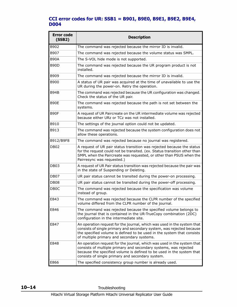
Hitachi Virtual Storage Platform Hitachi Universal Replicator User Guide
10–14 Troubleshooting
CCI error codes for UR: SSB1 = B901, B9E0, B9E1, B9E2, B9E4, D004
Error code (SSB2) Description
B902 The command was rejected because the mirror ID is invalid.
B907 The command was rejected because the volume status was SMPL.
B90A The S-VOL hide mode is not supported.
B90D The command was rejected because the UR program product is not installed.
B909 The command was rejected because the mirror ID is invalid.
B900 A status of UR pair was acquired at the time of unavailable to use the UR during the power-on. Retry the operation.
B94B The command was rejected because the UR configuration was changed. Check the status of the UR pair.
B90E The command was rejected because the path is not set between the systems.
B90F A request of UR Paircreate on the UR intermediate volume was rejected because either URz or TCz was not installed.
B910 The settings of the journal option could not be updated.
B913 The command was rejected because the system configuration does not allow these operations.
B912/B9F8 The command was rejected because no journal was registered.
DB02 A request of UR pair status transition was rejected because the status for the request could not be transited. (ex. Status transition other than SMPL when the Paircreate was requested, or other than PSUS when the Pairresync was requested.)
DB03 A request of UR Pair status transition was rejected because the pair was in the state of Suspending or Deleting.
DB07 UR pair status cannot be transited during the power-on processing.
DB08 UR pair status cannot be transited during the power-off processing.
DB0C The command was rejected because the specification was volume instead of group.
E843 The command was rejected because the CLPR number of the specified volume differed from the CLPR number of the journal.
E846 The command was rejected because the specified volume belongs to the journal that is contained in the UR-TrueCopy combination (2DC) configuration in the intermediate site.
E847 An operation request for the journal, which was used in the system that consists of single primary and secondary system, was rejected because the specified volume is defined to be used in the system that consists of multiple primary and secondary systems.
E848 An operation request for the journal, which was used in the system that consists of multiple primary and secondary systems, was rejected because the specified volume is defined to be used in the system that consists of single primary and secondary system.
E866 The specified consistency group number is already used.
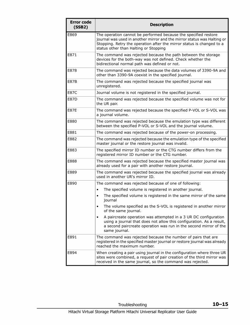
Troubleshooting 10–15Hitachi Virtual Storage Platform Hitachi Universal Replicator User Guide
E869 The operation cannot be performed because the specified restore journal was used in another mirror and the mirror status was Halting or Stopping. Retry the operation after the mirror status is changed to a status other than Halting or Stopping
E871 The command was rejected because the path between the storage devices for the both-way was not defined. Check whether the bidirectional normal path was defined or not.
E878 The command was rejected because the data volumes of 3390-9A and other than 3390-9A coexist in the specified journal.
E87B The command was rejected because the specified journal was unregistered.
E87C Journal volume is not registered in the specified journal.
E87D The command was rejected because the specified volume was not for the UR pair.
E87E The command was rejected because the specified P-VOL or S-VOL was a journal volume.
E880 The command was rejected because the emulation type was different between the specified P-VOL or S-VOL and the journal volume.
E881 The command was rejected because of the power-on processing.
E882 The command was rejected because the emulation type of the specified master journal or the restore journal was invalid.
E883 The specified mirror ID number or the CTG number differs from the registered mirror ID number or the CTG number.
E888 The command was rejected because the specified master journal was already used for a pair with another restore journal.
E889 The command was rejected because the specified journal was already used in another UR's mirror ID.
E890 The command was rejected because of one of following:• The specified volume is registered in another journal.• The specified volume is registered in the same mirror of the same
journal• The volume specified as the S-VOL is registered in another mirror
of the same journal.• A paircreate operation was attempted in a 3 UR DC configuration
using a journal that does not allow this configuration. As a result, a second paircreate operation was run in the second mirror of the same journal.
E891 The command was rejected because the number of pairs that are registered in the specified master journal or restore journal was already reached the maximum number.
E894 When creating a pair using journal in the configuration where three UR sites were combined, a request of pair creation of the third mirror was received in the same journal, so the command was rejected.
Error code (SSB2) Description
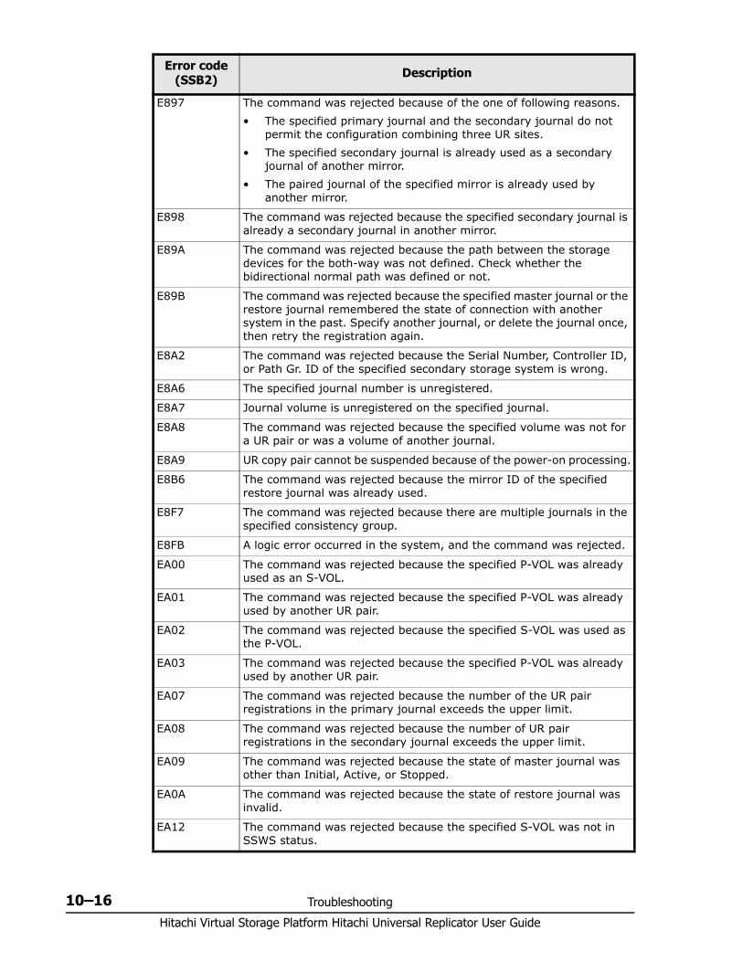
Hitachi Virtual Storage Platform Hitachi Universal Replicator User Guide
10–16 Troubleshooting
E897 The command was rejected because of the one of following reasons.• The specified primary journal and the secondary journal do not
permit the configuration combining three UR sites.• The specified secondary journal is already used as a secondary
journal of another mirror.• The paired journal of the specified mirror is already used by
another mirror.
E898 The command was rejected because the specified secondary journal is already a secondary journal in another mirror.
E89A The command was rejected because the path between the storage devices for the both-way was not defined. Check whether the bidirectional normal path was defined or not.
E89B The command was rejected because the specified master journal or the restore journal remembered the state of connection with another system in the past. Specify another journal, or delete the journal once, then retry the registration again.
E8A2 The command was rejected because the Serial Number, Controller ID, or Path Gr. ID of the specified secondary storage system is wrong.
E8A6 The specified journal number is unregistered.
E8A7 Journal volume is unregistered on the specified journal.
E8A8 The command was rejected because the specified volume was not for a UR pair or was a volume of another journal.
E8A9 UR copy pair cannot be suspended because of the power-on processing.
E8B6 The command was rejected because the mirror ID of the specified restore journal was already used.
E8F7 The command was rejected because there are multiple journals in the specified consistency group.
E8FB A logic error occurred in the system, and the command was rejected.
EA00 The command was rejected because the specified P-VOL was already used as an S-VOL.
EA01 The command was rejected because the specified P-VOL was already used by another UR pair.
EA02 The command was rejected because the specified S-VOL was used as the P-VOL.
EA03 The command was rejected because the specified P-VOL was already used by another UR pair.
EA07 The command was rejected because the number of the UR pair registrations in the primary journal exceeds the upper limit.
EA08 The command was rejected because the number of UR pair registrations in the secondary journal exceeds the upper limit.
EA09 The command was rejected because the state of master journal was other than Initial, Active, or Stopped.
EA0A The command was rejected because the state of restore journal was invalid.
EA12 The command was rejected because the specified S-VOL was not in SSWS status.
Error code (SSB2) Description
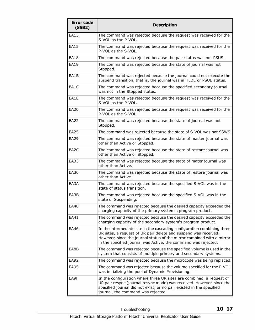
Troubleshooting 10–17Hitachi Virtual Storage Platform Hitachi Universal Replicator User Guide
EA13 The command was rejected because the request was received for the S-VOL as the P-VOL.
EA15 The command was rejected because the request was received for the P-VOL as the S-VOL.
EA18 The command was rejected because the pair status was not PSUS.
EA19 The command was rejected because the state of journal was not Stopped.
EA1B The command was rejected because the journal could not execute the suspend transition, that is, the journal was in HLDE or PSUE status.
EA1C The command was rejected because the specified secondary journal was not in the Stopped status.
EA1E The command was rejected because the request was received for the S-VOL as the P-VOL.
EA20 The command was rejected because the request was received for the P-VOL as the S-VOL.
EA22 The command was rejected because the state of journal was not Stopped.
EA25 The command was rejected because the state of S-VOL was not SSWS.
EA29 The command was rejected because the state of master journal was other than Active or Stopped.
EA2C The command was rejected because the state of restore journal was other than Active or Stopped.
EA33 The command was rejected because the state of mater journal was other than Active.
EA36 The command was rejected because the state of restore journal was other than Active.
EA3A The command was rejected because the specified S-VOL was in the state of status transition.
EA3B The command was rejected because the specified S-VOL was in the state of Suspending.
EA40 The command was rejected because the desired capacity exceeded the charging capacity of the primary system's program product.
EA41 The command was rejected because the desired capacity exceeded the charging capacity of the secondary system's program product.
EA46 In the intermediate site in the cascading configuration combining three UR sites, a request of UR pair delete and suspend was received. However, since the journal status of the mirror combined with a mirror in the specified journal was Active, the command was rejected.
EA8B The command was rejected because the specified volume is used in the system that consists of multiple primary and secondary systems.
EA92 The command was rejected because the microcode was being replaced.
EA95 The command was rejected because the volume specified for the P-VOL was initializing the pool of Dynamic Provisioning.
EA9F In the configuration where three UR sites are combined, a request of UR pair resync (journal resync mode) was received. However, since the specified journal did not exist, or no pair existed in the specified journal, the command was rejected.
Error code (SSB2) Description
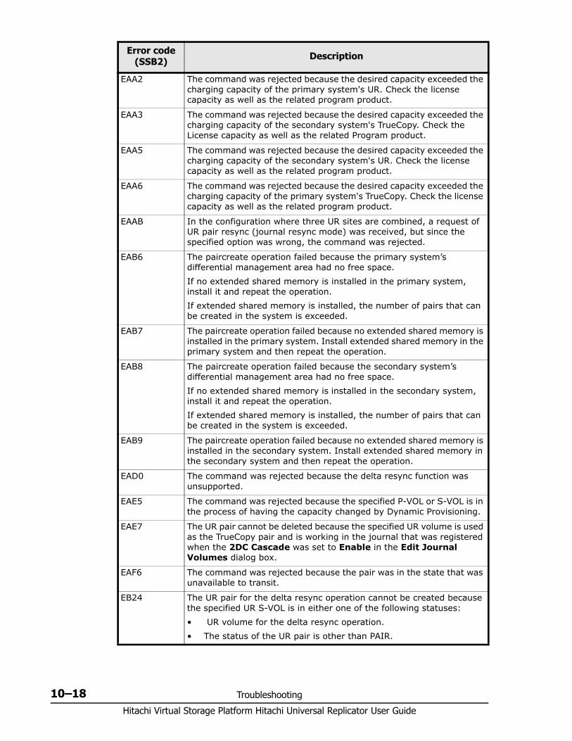
Hitachi Virtual Storage Platform Hitachi Universal Replicator User Guide
10–18 Troubleshooting
EAA2 The command was rejected because the desired capacity exceeded the charging capacity of the primary system's UR. Check the license capacity as well as the related program product.
EAA3 The command was rejected because the desired capacity exceeded the charging capacity of the secondary system's TrueCopy. Check the License capacity as well as the related Program product.
EAA5 The command was rejected because the desired capacity exceeded the charging capacity of the secondary system's UR. Check the license capacity as well as the related program product.
EAA6 The command was rejected because the desired capacity exceeded the charging capacity of the primary system's TrueCopy. Check the license capacity as well as the related program product.
EAAB In the configuration where three UR sites are combined, a request of UR pair resync (journal resync mode) was received, but since the specified option was wrong, the command was rejected.
EAB6 The paircreate operation failed because the primary system’s differential management area had no free space. If no extended shared memory is installed in the primary system, install it and repeat the operation. If extended shared memory is installed, the number of pairs that can be created in the system is exceeded.
EAB7 The paircreate operation failed because no extended shared memory is installed in the primary system. Install extended shared memory in the primary system and then repeat the operation.
EAB8 The paircreate operation failed because the secondary system’s differential management area had no free space. If no extended shared memory is installed in the secondary system, install it and repeat the operation. If extended shared memory is installed, the number of pairs that can be created in the system is exceeded.
EAB9 The paircreate operation failed because no extended shared memory is installed in the secondary system. Install extended shared memory in the secondary system and then repeat the operation.
EAD0 The command was rejected because the delta resync function was unsupported.
EAE5 The command was rejected because the specified P-VOL or S-VOL is in the process of having the capacity changed by Dynamic Provisioning.
EAE7 The UR pair cannot be deleted because the specified UR volume is used as the TrueCopy pair and is working in the journal that was registered when the 2DC Cascade was set to Enable in the Edit Journal Volumes dialog box.
EAF6 The command was rejected because the pair was in the state that was unavailable to transit.
EB24 The UR pair for the delta resync operation cannot be created because the specified UR S-VOL is in either one of the following statuses:• UR volume for the delta resync operation.• The status of the UR pair is other than PAIR.
Error code (SSB2) Description
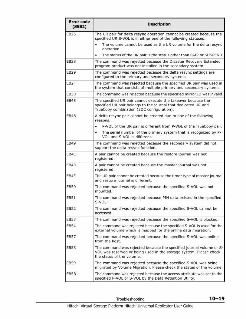
Troubleshooting 10–19Hitachi Virtual Storage Platform Hitachi Universal Replicator User Guide
EB25 The UR pair for delta resync operation cannot be created because the specified UR S-VOL is in either one of the following statuses:• The volume cannot be used as the UR volume for the delta resync
operation.• The status of the UR pair is the status other than PAIR or SUSPEND.
EB28 The command was rejected because the Disaster Recovery Extended program product was not installed in the secondary system.
EB29 The command was rejected because the delta resync settings are configured to the primary and secondary systems.
EB2F The command was rejected because the specified UR pair was used in the system that consists of multiple primary and secondary systems.
EB30 The command was rejected because the specified mirror ID was invalid.
EB45 The specified UR pair cannot execute the takeover because the specified UR pair belongs to the journal that dedicated UR and TrueCopy combination (2DC configuration).
EB48 A delta resync pair cannot be created due to one of the following reasons.• P-VOL of the UR pair is different from P-VOL of the TrueCopy pair.• The serial number of the primary system that is recognized by P-
VOL and S-VOL is different.
EB49 The command was rejected because the secondary system did not support the delta resync function.
EB4C A pair cannot be created because the restore journal was not registered.
EB4D A pair cannot be created because the master journal was not registered.
EB4F The UR pair cannot be created because the timer type of master journal and restore journal is different.
EB50 The command was rejected because the specified S-VOL was not mounted.
EB51 The command was rejected because PIN data existed in the specified S-VOL.
EB52 The command was rejected because the specified S-VOL cannot be accessed.
EB53 The command was rejected because the specified S-VOL is blocked.
EB54 The command was rejected because the specified S-VOL is used for the external volume which is mapped for the online data migration.
EB57 The command was rejected because the specified S-VOL was online from the host.
EB58 The command was rejected because the specified journal volume or S-VOL was reserved or being used in the storage system. Please check the status of the volume.
EB59 The command was rejected because the specified S-VOL was being migrated by Volume Migration. Please check the status of the volume.
EB5B The command was rejected because the access attribute was set to the specified P-VOL or S-VOL by the Data Retention Utility.
Error code (SSB2) Description
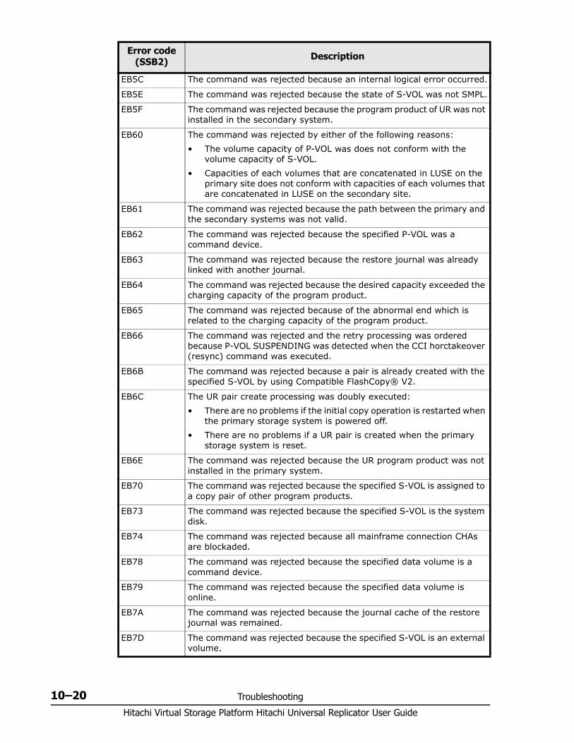
Hitachi Virtual Storage Platform Hitachi Universal Replicator User Guide
10–20 Troubleshooting
EB5C The command was rejected because an internal logical error occurred.
EB5E The command was rejected because the state of S-VOL was not SMPL.
EB5F The command was rejected because the program product of UR was not installed in the secondary system.
EB60 The command was rejected by either of the following reasons: • The volume capacity of P-VOL was does not conform with the
volume capacity of S-VOL.• Capacities of each volumes that are concatenated in LUSE on the
primary site does not conform with capacities of each volumes that are concatenated in LUSE on the secondary site.
EB61 The command was rejected because the path between the primary and the secondary systems was not valid.
EB62 The command was rejected because the specified P-VOL was a command device.
EB63 The command was rejected because the restore journal was already linked with another journal.
EB64 The command was rejected because the desired capacity exceeded the charging capacity of the program product.
EB65 The command was rejected because of the abnormal end which is related to the charging capacity of the program product.
EB66 The command was rejected and the retry processing was ordered because P-VOL SUSPENDING was detected when the CCI horctakeover (resync) command was executed.
EB6B The command was rejected because a pair is already created with the specified S-VOL by using Compatible FlashCopy® V2.
EB6C The UR pair create processing was doubly executed:• There are no problems if the initial copy operation is restarted when
the primary storage system is powered off.• There are no problems if a UR pair is created when the primary
storage system is reset.
EB6E The command was rejected because the UR program product was not installed in the primary system.
EB70 The command was rejected because the specified S-VOL is assigned to a copy pair of other program products.
EB73 The command was rejected because the specified S-VOL is the system disk.
EB74 The command was rejected because all mainframe connection CHAs are blockaded.
EB78 The command was rejected because the specified data volume is a command device.
EB79 The command was rejected because the specified data volume is online.
EB7A The command was rejected because the journal cache of the restore journal was remained.
EB7D The command was rejected because the specified S-VOL is an external volume.
Error code (SSB2) Description
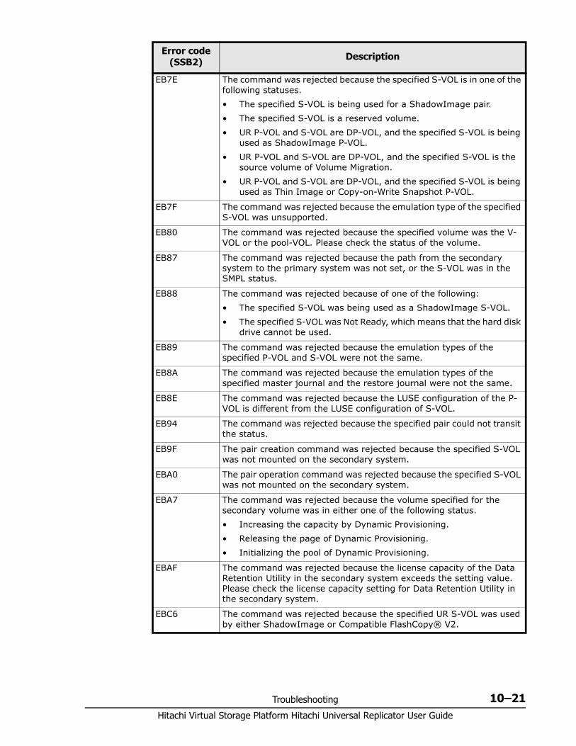
Troubleshooting 10–21Hitachi Virtual Storage Platform Hitachi Universal Replicator User Guide
EB7E The command was rejected because the specified S-VOL is in one of the following statuses.• The specified S-VOL is being used for a ShadowImage pair.• The specified S-VOL is a reserved volume.• UR P-VOL and S-VOL are DP-VOL, and the specified S-VOL is being
used as ShadowImage P-VOL.• UR P-VOL and S-VOL are DP-VOL, and the specified S-VOL is the
source volume of Volume Migration.• UR P-VOL and S-VOL are DP-VOL, and the specified S-VOL is being
used as Thin Image or Copy-on-Write Snapshot P-VOL.
EB7F The command was rejected because the emulation type of the specified S-VOL was unsupported.
EB80 The command was rejected because the specified volume was the V-VOL or the pool-VOL. Please check the status of the volume.
EB87 The command was rejected because the path from the secondary system to the primary system was not set, or the S-VOL was in the SMPL status.
EB88 The command was rejected because of one of the following:• The specified S-VOL was being used as a ShadowImage S-VOL.• The specified S-VOL was Not Ready, which means that the hard disk
drive cannot be used.
EB89 The command was rejected because the emulation types of the specified P-VOL and S-VOL were not the same.
EB8A The command was rejected because the emulation types of the specified master journal and the restore journal were not the same.
EB8E The command was rejected because the LUSE configuration of the P-VOL is different from the LUSE configuration of S-VOL.
EB94 The command was rejected because the specified pair could not transit the status.
EB9F The pair creation command was rejected because the specified S-VOL was not mounted on the secondary system.
EBA0 The pair operation command was rejected because the specified S-VOL was not mounted on the secondary system.
EBA7 The command was rejected because the volume specified for the secondary volume was in either one of the following status.• Increasing the capacity by Dynamic Provisioning.• Releasing the page of Dynamic Provisioning.• Initializing the pool of Dynamic Provisioning.
EBAF The command was rejected because the license capacity of the Data Retention Utility in the secondary system exceeds the setting value. Please check the license capacity setting for Data Retention Utility in the secondary system.
EBC6 The command was rejected because the specified UR S-VOL was used by either ShadowImage or Compatible FlashCopy® V2.
Error code (SSB2) Description
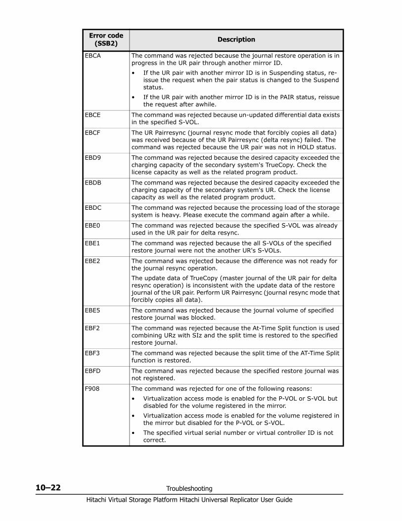
Hitachi Virtual Storage Platform Hitachi Universal Replicator User Guide
10–22 Troubleshooting
EBCA The command was rejected because the journal restore operation is in progress in the UR pair through another mirror ID.• If the UR pair with another mirror ID is in Suspending status, re-
issue the request when the pair status is changed to the Suspend status.
• If the UR pair with another mirror ID is in the PAIR status, reissue the request after awhile.
EBCE The command was rejected because un-updated differential data exists in the specified S-VOL.
EBCF The UR Pairresync (journal resync mode that forcibly copies all data) was received because of the UR Pairresync (delta resync) failed. The command was rejected because the UR pair was not in HOLD status.
EBD9 The command was rejected because the desired capacity exceeded the charging capacity of the secondary system's TrueCopy. Check the license capacity as well as the related program product.
EBDB The command was rejected because the desired capacity exceeded the charging capacity of the secondary system's UR. Check the license capacity as well as the related program product.
EBDC The command was rejected because the processing load of the storage system is heavy. Please execute the command again after a while.
EBE0 The command was rejected because the specified S-VOL was already used in the UR pair for delta resync.
EBE1 The command was rejected because the all S-VOLs of the specified restore journal were not the another UR's S-VOLs.
EBE2 The command was rejected because the difference was not ready for the journal resync operation.The update data of TrueCopy (master journal of the UR pair for delta resync operation) is inconsistent with the update data of the restore journal of the UR pair. Perform UR Pairresync (journal resync mode that forcibly copies all data).
EBE5 The command was rejected because the journal volume of specified restore journal was blocked.
EBF2 The command was rejected because the At-Time Split function is used combining URz with SIz and the split time is restored to the specified restore journal.
EBF3 The command was rejected because the split time of the AT-Time Split function is restored.
EBFD The command was rejected because the specified restore journal was not registered.
F908 The command was rejected for one of the following reasons:• Virtualization access mode is enabled for the P-VOL or S-VOL but
disabled for the volume registered in the mirror.• Virtualization access mode is enabled for the volume registered in
the mirror but disabled for the P-VOL or S-VOL.• The specified virtual serial number or virtual controller ID is not
correct.
Error code (SSB2) Description
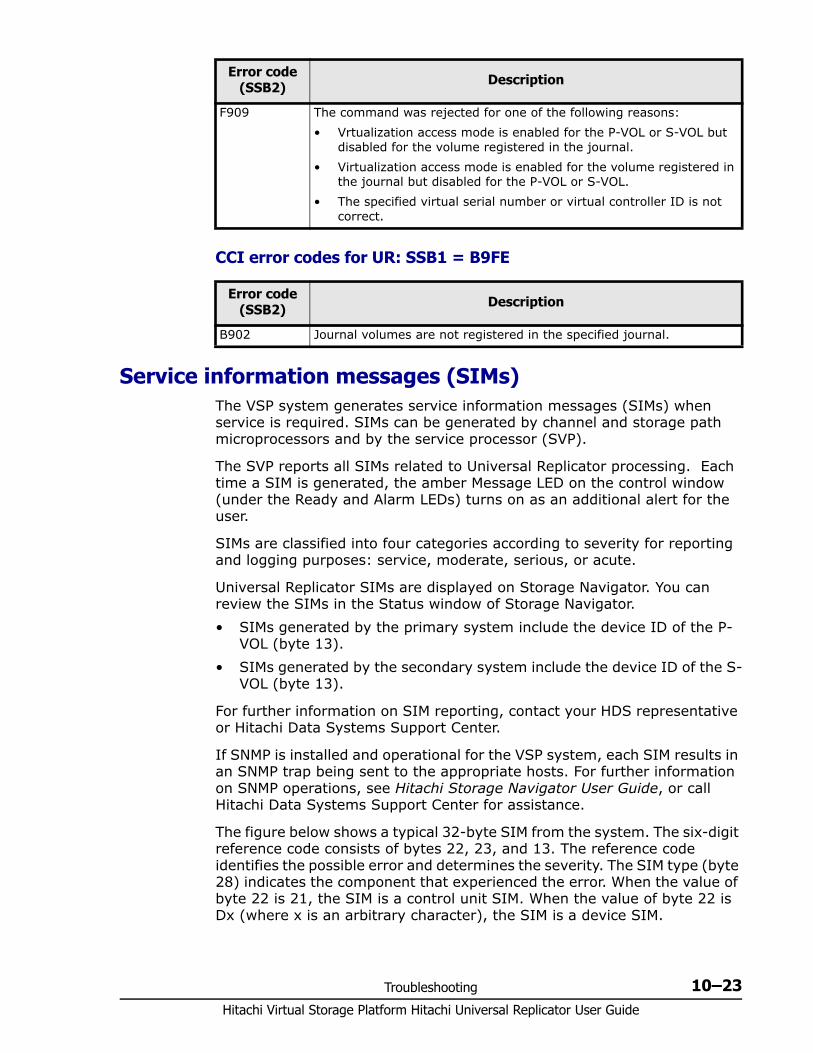
Troubleshooting 10–23Hitachi Virtual Storage Platform Hitachi Universal Replicator User Guide
CCI error codes for UR: SSB1 = B9FE
Service information messages (SIMs) The VSP system generates service information messages (SIMs) when service is required. SIMs can be generated by channel and storage path microprocessors and by the service processor (SVP).
The SVP reports all SIMs related to Universal Replicator processing. Each time a SIM is generated, the amber Message LED on the control window (under the Ready and Alarm LEDs) turns on as an additional alert for the user.
SIMs are classified into four categories according to severity for reporting and logging purposes: service, moderate, serious, or acute.
Universal Replicator SIMs are displayed on Storage Navigator. You can review the SIMs in the Status window of Storage Navigator.• SIMs generated by the primary system include the device ID of the P-
VOL (byte 13).• SIMs generated by the secondary system include the device ID of the S-
VOL (byte 13).
For further information on SIM reporting, contact your HDS representative or Hitachi Data Systems Support Center.
If SNMP is installed and operational for the VSP system, each SIM results in an SNMP trap being sent to the appropriate hosts. For further information on SNMP operations, see Hitachi Storage Navigator User Guide, or call Hitachi Data Systems Support Center for assistance.
The figure below shows a typical 32-byte SIM from the system. The six-digit reference code consists of bytes 22, 23, and 13. The reference code identifies the possible error and determines the severity. The SIM type (byte 28) indicates the component that experienced the error. When the value of byte 22 is 21, the SIM is a control unit SIM. When the value of byte 22 is Dx (where x is an arbitrary character), the SIM is a device SIM.
F909 The command was rejected for one of the following reasons:• Vrtualization access mode is enabled for the P-VOL or S-VOL but
disabled for the volume registered in the journal.• Virtualization access mode is enabled for the volume registered in
the journal but disabled for the P-VOL or S-VOL.• The specified virtual serial number or virtual controller ID is not
correct.
Error code (SSB2) Description
Error code (SSB2) Description
B902 Journal volumes are not registered in the specified journal.
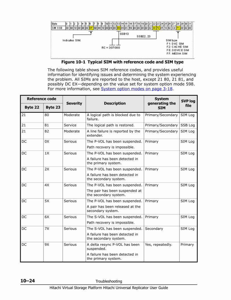
Hitachi Virtual Storage Platform Hitachi Universal Replicator User Guide
10–24 Troubleshooting
The following table shows SIM reference codes, and provides useful information for identifying issues and determining the system experiencing the problem. All SIMs are reported to the host, except 21 80, 21 81, and possibly DC EX—depending on the value set for system option mode 598. For more information, see System option modes on page 3-18.
Figure 10-1 Typical SIM with reference code and SIM type
Reference codeSeverity Description
System generating the
SIM
SVP log fileByte 22 Byte 23
21 80 Moderate A logical path is blocked due to failure.
Primary/Secondary SIM Log
21 81 Service The logical path is restored. Primary/Secondary SSB Log
21 82 Moderate A line failure is reported by the extender.
Primary/Secondary SIM Log
DC 0X Serious The P-VOL has been suspended.Path recovery is impossible.
Primary SIM Log
DC 1X Serious The P-VOL has been suspended.A failure has been detected in the primary system.
Primary SIM Log
DC 2X Serious The P-VOL has been suspended.A failure has been detected in the secondary system.
Primary SIM Log
DC 4X Serious The P-VOL has been suspended.The pair has been suspended at the secondary system.
Primary SIM Log
DC 5X Serious The P-VOL has been suspended.A pair has been released at the secondary system.
Primary SIM Log
DC 6X Serious The S-VOL has been suspended.Path recovery is impossible.
Primary SIM Log
DC 7X Serious The S-VOL has been suspended.A failure has been detected in the secondary system.
Secondary SIM Log
DC 9X Serious A delta resync P-VOL has been suspended.A failure has been detected in the primary system.
Yes, repeatedly. Primary
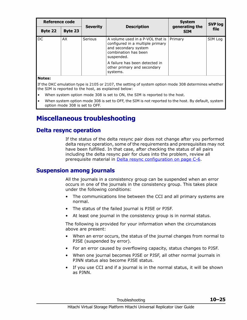
Troubleshooting 10–25Hitachi Virtual Storage Platform Hitachi Universal Replicator User Guide
Miscellaneous troubleshooting
Delta resync operationIf the status of the delta resync pair does not change after you performed delta resync operation, some of the requirements and prerequisites may not have been fulfilled. In that case, after checking the status of all pairs including the delta resync pair for clues into the problem, review all prerequisite material in Delta resync configuration on page C-6.
Suspension among journals All the journals in a consistency group can be suspended when an error occurs in one of the journals in the consistency group. This takes place under the following conditions:• The communications line between the CCI and all primary systems are
normal.• The status of the failed journal is PJSE or PJSF.• At least one journal in the consistency group is in normal status.
The following is provided for your information when the circumstances above are present:• When an error occurs, the status of the journal changes from normal to
PJSE (suspended by error).• For an error caused by overflowing capacity, status changes to PJSF.• When one journal becomes PJSE or PJSF, all other normal journals in
PJNN status also become PJSE status.• If you use CCI and if a journal is in the normal status, it will be shown
as PJNN.
DC AX Serious A volume used in a P-VOL that is configured in a multiple primary and secondary system combination has been suspended.A failure has been detected in other primary and secondary systems.
Primary SIM Log
Notes:If the DKC emulation type is 2105 or 2107, the setting of system option mode 308 determines whether the SIM is reported to the host, as explained below:• When system option mode 308 is set to ON, the SIM is reported to the host.• When system option mode 308 is set to OFF, the SIM is not reported to the host. By default, system
option mode 308 is set to OFF.
Reference codeSeverity Description
System generating the
SIM
SVP log fileByte 22 Byte 23

Hitachi Virtual Storage Platform Hitachi Universal Replicator User Guide
10–26 Troubleshooting
Note that if some pairs in the journal become suspended by error but the whole journal does not become suspended, the status of other journals will not change
Calling the Hitachi Data Systems Support CenterIf you need to call the Hitachi Data Systems Support Center, please provide as much information about the problem as possible, including: • The circumstances surrounding the error or failure.• The content of any error messages displayed on the host systems.• The content of any error messages displayed on Storage Navigator.• The Storage Navigator configuration information (use the FD Dump
Tool).• The service information messages (SIMs), including reference codes and
severity levels, displayed by Storage Navigator.
The HDS customer support staff is available 24 hours a day, seven days a week. If you need technical support, log on to the HDS Support Portal for contact information: https://hdssupport.hds.com
A
3 UR data-center configurations A–1Hitachi Virtual Storage Platform Hitachi Universal Replicator User Guide
3 UR data-center configurations
With Universal Replicator, a volume at the primary site can be backed up to second and third remote UR sites in 3 data center (3DC) configurations.
This appendix provides planning and setup information for 3-Universal Replicator data center configurations.
□ Overview
□ 3 UR DC cascade configuration
□ 3 UR DC multi-target configuration
Hitachi Virtual Storage Platform Hitachi Universal Replicator User Guide
A–2 3 UR data-center configurations
OverviewYou can configure a Universal Replicator system using multiple VSPs in the following configurations for disaster recovery: • 3-data center cascade (3DC cascade). Data in the UR P-VOL is paired
with an S-VOL in the UR intermediate site; and then the intermediate site S-VOL is paired (becoming a P-VOL) with an S-VOL in the UR remote site. See the figure and information in 3 UR DC cascade configuration on page A-2.
• 3-data center multi-target configuration (3DC multi-target). Data in the UR P-VOL is paired with two S-VOLs—in two remote UR locations. See the figure and information in 3 UR DC multi-target configuration on page A-6
• An additional option for cascade and multi-target configurations is the delta resync, which pairs the local P-VOL and one of the remote S-VOLs. The delta resync provides one more option for maintaining a close copy of production data for use as a backup in the event of failure at the other sites. The delta resync is slightly different for the cascading and mu lti-target configurations. See the following sections for details.
• 3DC configurations can be set up using TrueCopy and UR also. See Sharing volumes with TrueCopy on page C-2 for information.
3 UR DC cascade configurationIn a multi-target configuration, data is copied from the local site to two remote sites.In a cascading configuration, data is copied from the primary (local) site to an intermediate site and then to a remote site.
The intermediate site volume acts as:• The S-VOL for the local-intermediate pair• The P-VOL for with the intermediate-remote pair
In addition, you can create a delta resync pair from the local site to the remote site. Once created, the delta resync pair remains split unless the S-VOL is needed for disaster recovery. Though the pair is split, the S-VOL contains all but the latest production differential data. This is because the volume is also the S-VOL for the pair from the intermediate site and so is updated regularly.

3 UR data-center configurations A–3Hitachi Virtual Storage Platform Hitachi Universal Replicator User Guide
Mirror IDs are assigned to each pair. You assign arbitrary numbers as mirror IDs. For example:• Local site mirror ID: M)• Intermediate site secondary mirror ID: M; primary mirror ID: N)• Remote site secondary mirror ID: N
Related information• Failure recovery on page A-3• Requirements, restrictions, and notes on page A-3• Problems that can occur with delta resync on page A-5• Setting up the 3 UR DC cascade configuration on page A-5
Failure recoveryIn a 3DC cascading configuration with three UR sites, failure recovery utilizes the pair or volume whose status is normal.• If a failure occurs at the local site, business operations are moved to the
intermediate site.• If a failure occurs at the primary and intermediate sites, business
operations are moved to the remote site. • When failed sites are restored, data is copied to their pair volumes from
the current production site, business operations are returned to the local site, and all pairs are restored.
See Recovery for 3 UR DC cascade configuration on page 9-5 for recovery information and procedures.
Requirements, restrictions, and notes• Remote command devices must be assigned to two mirror IDs: one for
the primary-intermediate pair, and one for the intermediate-remote pair.
Hitachi Virtual Storage Platform Hitachi Universal Replicator User Guide
A–4 3 UR data-center configurations
• The VSP system at the three sites require registration of two mirrors in one journal (since two pairs use the same volume). This is done using the Edit Journal Volumes dialog box in Storage Navigator, and is discussed in the setup procedure.Alternatively, if microprogram version 70-03-xx or higher is installed, you can use CCI to register the mirrors in the journal. Contact Hitachi Data Systems support to ensure that you have the latest firmware version available.
• Perform one pair operation in a 3 UR DC configuration at a time. Performing pair operations on the two pairs at the same time results in failure. If this occurs, correct the pair statuses then perform the operations one-at-a-time.
• LUSE volumes cannot be used as pair volumes.• Create the local-intermediate pair first; then create the intermediate-
remote pair.• Make sure that performance for the intermediate-remote data path is
the same as performance for the local-intermediate data path. Otherwise, the intermediate site’s journal volume may experience increased usage. If the usage rate reaches the threshold, the pair intermediate-remote pair is suspended.
• To maintain consistency among the pairs in related journals, make sure that all data volumes in the journals are used in pairs (with accompanying registered mirrors). If a data volume in the local site journal, for example, is not used in a pair, the number of data volumes in the journal may not be the same as the number in the secondary journal, and so consistency cannot be maintained.
• When creating the local-intermediate pair, set the mirror status for the intermediate-remote pair to Initial or Stopped.
• When creating the intermediate-remote pair, the P-VOL cannot be in COPY status in its role as the primary-to-intermediate S-VOL, or the pair will not be created.
• When splitting the intermediate-remote pair using flush mode, set the pair’s mirror status to Stopped.
• When splitting the intermediate-remote pair whose S-VOL is also the delta resync S-VOL, host I/O to the S-VOL will not be allowed even when you specify Enable for S-VOL Write in split procedure.
• When restoring the local-intermediate pair, the intermediate-remote pair is split automatically if its mirror status is PAIR.
• The local-intermediate pair cannot be restored when the mirror status for the intermediate-remote pair is COPY.
• When deleting the intermediate-remote pair: If Mirror is specified for Range, set the mirror status for either
cascade pair to Stopped. If Volume is specified for Range, set the mirror status for the
primary-intermediate pair to Stopped, or set pair status to SUSPEND.• Required pair and volume statuses for the delta resync operation:
3 UR data-center configurations A–5Hitachi Virtual Storage Platform Hitachi Universal Replicator User Guide
Delta resync P-VOL and S-VOL: HOLD UR P-VOL: PAIR or PSUE UR S-VOL: PAIR, PSUS, PSUE
• Differential data is stored in the master journal but may not be completely present after a failure. You can avoid delta resync failure by specifying that the entire P-VOL is copied to the delta resync S-VOL in this case. See the Delta resync Failure option in Changing options used by mirrors on page 8-5 for information.
• When you delete either cascading pair, the delta resync pair is also deleted.
Problems that can occur with delta resync
Journal data will not exist, and therefore the delta resync operation will not succeed, if the following occurs. Avoid these situations.• After splitting the intermediate-remote pair, the S-VOL is updated.• After the intermediate-remote pair is split and the journal volume at the
intermediate site then exceeds 70-percent as a result of updates from the primary site.
• When the delta resync P-VOL is updated and then data in the journal volume exceeds 70-percent.
The following provides solutions to other delta resync problems.• If the delta resync S-VOL status becomes HLDE, you cannot restore it to
HOLD by resynchronizing the pair. You must delete the delta resync pair and recreate it.
• If the delta resync pair’s status does not change after the delta resync operation, check that all requirements are fulfilled and that any problems explained in this topic have not occurred. Check the status of the UR pair and UR pair for delta resync operation, and make sure that all pairs are in the required status.
Setting up the 3 UR DC cascade configurationSet up a 3 UR DC cascade configuration using the following procedure. CCI is used to set up the configuration. To set up a 3DC cascade using UR and TrueCopy, see Procedure for setting up 3DC cascade on page C-4.1. Set up UR at the primary, intermediate, and remote sites and configure
ports. See:Configuring local and remote systems for UR on page 5-3Defining fibre-channel port attributes on page 5-2
Note: The S-VOL uses two mirror IDs because of its dual use in the 3DC cascade and delta resync configurations. The statuses shown above are required for the two mirrors as well as for the journal in which the UR pair for delta resync resides.
Hitachi Virtual Storage Platform Hitachi Universal Replicator User Guide
A–6 3 UR data-center configurations
2. Configure UR journals in the three sites. When you register a journal, UR 3DC is automatically enabled in the Edit Journal Volumes dialog box. This setting allows registration of two MUs in a journal, as required for the intermediate S-VOL/P-VOL. See Registering journal volumes in a journal on page 5-10 for more information about registering journals.
3. Create the pair in the first mirror, from the primary to the intermediate site. Specify a value from 0 to 3 as the Mirror ID.
4. When pair status becomes PAIR, create the pair in the second mirror, from the intermediate to the remote site. Specify the secondary journal and S-VOL used in the first mirror as the primary journal and P-VOL of the new pair.Select a Mirror ID from 0 to 3, though not the one used for the local site pair.Make sure pair status changes to PAIR before proceeding.
5. (Optional) Create a delta resync pair using the P-VOL in the local site mirror and the existing S-VOL in the remote site mirror.Select a Mirror ID from 0 to 3, though not those used in the other two mirrors in the configuration.
6. Assign remote command devices to the following: Local site’s primary-intermediate pair mirror ID Local site’s delta resync pair mirror ID Intermediate site’s primary-intermediate pair mirror ID Intermediate site’s intermediate-remote pair mirror ID Remote site’s intermediate-remote pair mirror ID Remote site’s delta resync pair mirror ID
3 UR DC multi-target configurationIn a multi-target configuration, data is copied from the local site to two remote sites.
The benefit of this configuration is that it provides a third copy of the data, helping to insure that business can continue in the event of a failure at the other two sites.
You can also create a delta resync pair from one remote site S-VOL to the other remote site S-VOL. Once created, the delta resync pair remains split unless the S-VOL is needed for disaster recovery.
Note: The Edit Journal Volumes dialog box setting, UR 3DC, cannot be changed in the dialog box. To disable, it is necessary to delete the journal, disable the setting, and then register the journal again.
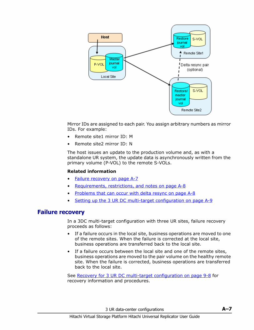
3 UR data-center configurations A–7Hitachi Virtual Storage Platform Hitachi Universal Replicator User Guide
Mirror IDs are assigned to each pair. You assign arbitrary numbers as mirror IDs. For example:• Remote site1 mirror ID: M• Remote site2 mirror ID: N
The host issues an update to the production volume and, as with a standalone UR system, the update data is asynchronously written from the primary volume (P-VOL) to the remote S-VOLs.
Related information• Failure recovery on page A-7• Requirements, restrictions, and notes on page A-8• Problems that can occur with delta resync on page A-8• Setting up the 3 UR DC multi-target configuration on page A-9
Failure recoveryIn a 3DC multi-target configuration with three UR sites, failure recovery proceeds as follows:• If a failure occurs in the local site, business operations are moved to one
of the remote sites. When the failure is corrected at the local site, business operations are transferred back to the local site.
• If a failure occurs between the local site and one of the remote sites, business operations are moved to the pair volume on the healthy remote site. When the failure is corrected, business operations are transferred back to the local site.
See Recovery for 3 UR DC multi-target configuration on page 9-8 for recovery information and procedures.

Hitachi Virtual Storage Platform Hitachi Universal Replicator User Guide
A–8 3 UR data-center configurations
Requirements, restrictions, and notes • The VSP system at the three sites require registration of two mirrors in
one journal (since two pairs use the same volume). This is done using the Edit Journal Volumes dialog box in Storage Navigator, and is discussed in the setup procedure.Alternatively, if microprogram version 70-03-xx or higher is installed, you can use CCI to register the mirrors in the journal. Contact Hitachi Data Systems support to ensure that you have the latest firmware version available.
• LUSE volumes cannot be used as pair volumes.• To maintain consistency among the pairs in related journals, make sure
that all data volumes in the journals are used in pairs (with accompanying registered mirrors). If a data volume in the local site journal, for example, is not used in a pair, the number of data volumes in the journal may not be the same as the number in the secondary journal, and so consistency cannot be maintained.
• The P-VOL in the first pair cannot be in COPY status when creating the second pair. In this case, the second pair will not be created.
• When multiple mirrors are registered in the journal, the P-VOL of one of the mirrors cannot be in COPY status when resynchronizing a pair of another mirror. In this case, the second pair will not be resynchronized.
• When splitting the pair whose S-VOL is also the delta resync S-VOL, host I/O to the S-VOL will not be allowed even when you specify Enable for S-VOL Write in the split procedure.
• When you delete either multi-target pair, the delta resync pair is also deleted.
• Delta resync operation requirements. These requirements are required for all volumes in the respective journals. Remote command devices are required for the two mirror IDs at the
delta resync primary and secondary sites. The data paths must be operational. CCI must be used for the delta resync operation. Required pair and volume statuses for the delta resync operation.
- Delta resync P-VOL and S-VOL: HOLD- UR P-VOL: SSWS- UR S-VOL: PAIR, PSUS, PSUE
Differential data is stored in the delta resync master journal but may not be completely present after a failure at delta resync primary site.
Problems that can occur with delta resync
Journal data will not exist, and therefore the delta resync operation will not succeed, if the following occurs. Avoid these situations.• After splitting the intermediate-remote pair, the S-VOL is updated.
3 UR data-center configurations A–9Hitachi Virtual Storage Platform Hitachi Universal Replicator User Guide
• After the intermediate-remote pair is split and the journal volume at the intermediate site then exceeds 70-percent as a result of updates from the primary site.
• When the delta resync P-VOL is updated and then data in the journal volume exceeds 70-percent.
• The Delta resync Failure option in the Change Mirror Options dialog box is disabled for the delta resync in a 3UR DC multi-target configuration.
The following provides solutions to other delta resync problems.• If the delta resync pair status becomes HLDE, you cannot restore it to
HOLD by resynchronizing the pair. You must delete the delta resync pair and recreate it.
• If the delta resync pair’s status does not change after the delta resync operation, some of the requirements explained in this topic may not have been fulfilled. In that case, check the status of the UR pair and UR pair for delta resync operation, and make sure that all pairs are in the required status.
• If the delta resync pair becomes suspended due to failure following the operation, if the problem is related to the P-VOL, resynchronize the pair. If the problem is related to the S-VOL, delete then recreate the pair.
Setting up the 3 UR DC multi-target configurationSet up a 3 UR DC multi-target configuration using the following procedure. CCI is used to set up the configuration.
To set up a 3DC multi-target using UR and TrueCopy, see Procedure for setting up 3DC multi-target on page C-6.1. Set up UR at the primary and two remote sites, and configure ports.
See:Configuring local and remote systems for UR on page 5-3Defining fibre-channel port attributes on page 5-2
2. Configure UR journals in three three sites. When you register a journal, UR 3DC is automatically enabled in the Edit Journal Volumes dialog box. This setting allows registration of two MUs in a journal, as required for the intermediate S-VOL/P-VOL. See Registering journal volumes in a journal on page 5-10 for more information about registering journals.
3. Create a pair in the first mirror, from the local site to a remote site. Specify a value from 0 to 3 as the Mirror ID.
4. When pair status becomes PAIR, create a pair in the second mirror, from the local site to the second remote site. Specify the same primary volume and journal used in the first mirror as the primary volume and journal in the new pair.Select a Mirror ID from 0 to 3, though not the one used for the first pair.
Note: The Edit Journal Volumes setting, UR 3DC, cannot be changed in the dialog box. To disable, it is necessary to delete the journal, disable the setting, and then register the journal again.
Hitachi Virtual Storage Platform Hitachi Universal Replicator User Guide
A–10 3 UR data-center configurations
Make sure pair status changes to PAIR before proceeding.5. (Optional) Create a delta resync pair using the secondary volumes in two
remote sites. Make sure to specify the S-VOL in the first remote site (and in the first mirror) as the primary volume. Specify the S-VOL in the second remote site (and in the second mirror) as the secondary volume.Select a Mirror ID from 0 to 3, though not those used in the other two mirrors in the configuration.
6. Assign remote command devices to the mirror IDs of the two pairs on the local site.
7. Assign the remote command device to the mirror IDs on two secondary sites. Additionally, assign the remote command device to the mirror ID of the UR pair for delta resync operation.
8. Assign remote command devices to the following: Mirror IDs of the two multi-target pairs on the local site Mirror IDs of the multi-target pairs on the two remote sites Mirror ID of the delta resync pair on the two remote sites
There should be a total of six remote devices—two each on the three sites.
B
Sharing volumes B–1Hitachi Virtual Storage Platform Hitachi Universal Replicator User Guide
Sharing volumes
This appendix discusses other Virtual Storage Platform software volumes that can be shared with Universal Replicator volumes.
Because TrueCopy and ShadowImage volumes can be used extensively with Universal Replicator, complete information for these configurations is provided in:
Configurations with TrueCopy on page C-1
Configurations with ShadowImage on page D-1.
□ Volume types that can be shared with Universal Replicator
□ Cache Residency Manager
□ Data Retention Utility
□ Dynamic Provisioning
□ High Availability Manager (HAM)
□ LUN Expansion (LUSE)
□ LUN Manager
□ Thin Image and Copy-on-Write Snapshot
□ Virtual LUN
□ Volume Migration
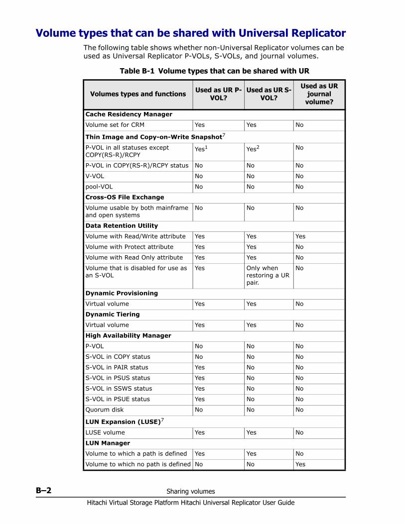
Hitachi Virtual Storage Platform Hitachi Universal Replicator User Guide
B–2 Sharing volumes
Volume types that can be shared with Universal ReplicatorThe following table shows whether non-Universal Replicator volumes can be used as Universal Replicator P-VOLs, S-VOLs, and journal volumes.
Table B-1 Volume types that can be shared with UR
Volumes types and functions Used as UR P-VOL?
Used as UR S-VOL?
Used as UR journal
volume?
Cache Residency Manager
Volume set for CRM Yes Yes No
Thin Image and Copy-on-Write Snapshot7
P-VOL in all statuses except COPY(RS-R)/RCPY
Yes1 Yes2 No
P-VOL in COPY(RS-R)/RCPY status No No No
V-VOL No No No
pool-VOL No No No
Cross-OS File Exchange
Volume usable by both mainframe and open systems
No No No
Data Retention Utility
Volume with Read/Write attribute Yes Yes Yes
Volume with Protect attribute Yes Yes No
Volume with Read Only attribute Yes Yes No
Volume that is disabled for use as an S-VOL
Yes Only when restoring a UR pair.
No
Dynamic Provisioning
Virtual volume Yes Yes No
Dynamic Tiering
Virtual volume Yes Yes No
High Availability Manager
P-VOL No No No
S-VOL in COPY status No No No
S-VOL in PAIR status Yes No No
S-VOL in PSUS status Yes No No
S-VOL in SSWS status Yes No No
S-VOL in PSUE status Yes No No
Quorum disk No No No
LUN Expansion (LUSE)7
LUSE volume Yes Yes No
LUN Manager
Volume to which a path is defined Yes Yes No
Volume to which no path is defined No No Yes
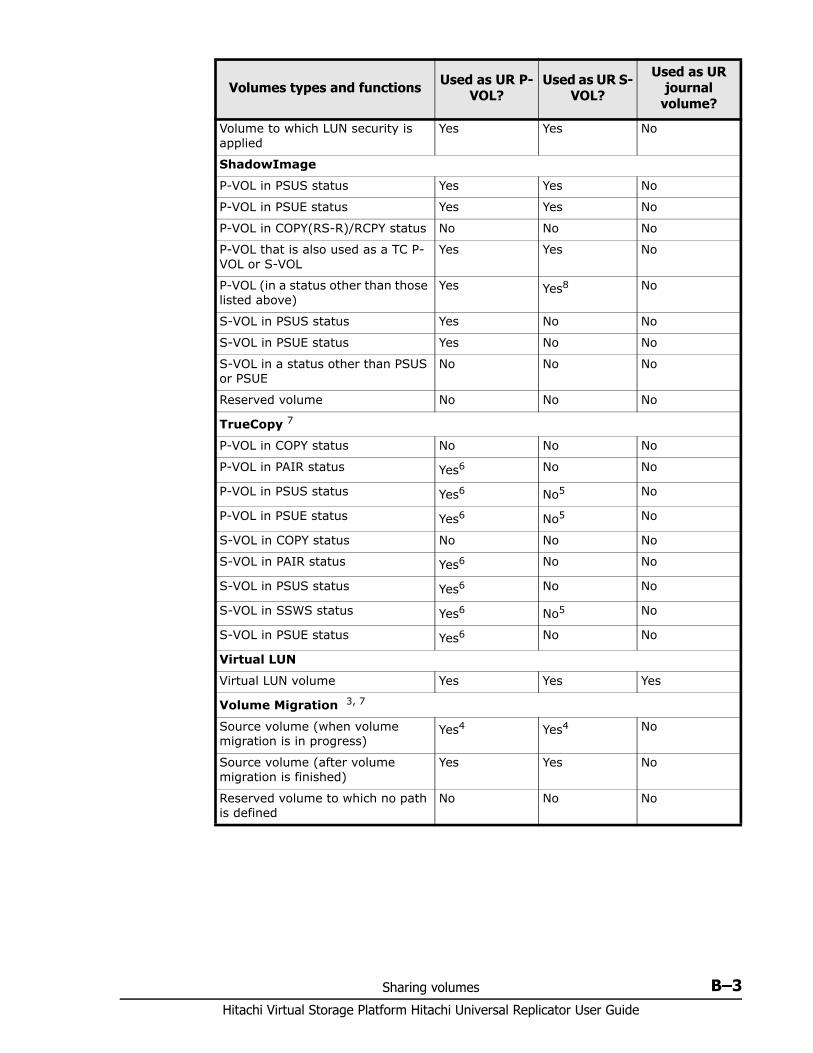
Sharing volumes B–3Hitachi Virtual Storage Platform Hitachi Universal Replicator User Guide
Volume to which LUN security is applied
Yes Yes No
ShadowImage
P-VOL in PSUS status Yes Yes No
P-VOL in PSUE status Yes Yes No
P-VOL in COPY(RS-R)/RCPY status No No No
P-VOL that is also used as a TC P-VOL or S-VOL
Yes Yes No
P-VOL (in a status other than those listed above)
Yes Yes8 No
S-VOL in PSUS status Yes No No
S-VOL in PSUE status Yes No No
S-VOL in a status other than PSUS or PSUE
No No No
Reserved volume No No No
TrueCopy 7
P-VOL in COPY status No No No
P-VOL in PAIR status Yes6 No No
P-VOL in PSUS status Yes6 No5 No
P-VOL in PSUE status Yes6 No5 No
S-VOL in COPY status No No No
S-VOL in PAIR status Yes6 No No
S-VOL in PSUS status Yes6 No No
S-VOL in SSWS status Yes6 No5 No
S-VOL in PSUE status Yes6 No No
Virtual LUN
Virtual LUN volume Yes Yes Yes
Volume Migration 3, 7
Source volume (when volume migration is in progress)
Yes4 Yes4 No
Source volume (after volume migration is finished)
Yes Yes No
Reserved volume to which no path is defined
No No No
Volumes types and functions Used as UR P-VOL?
Used as UR S-VOL?
Used as UR journal
volume?
Hitachi Virtual Storage Platform Hitachi Universal Replicator User Guide
B–4 Sharing volumes
The following topics clarify key information regarding shared volumes.
Cache Residency Manager You can perform Cache Residency Manager operations on a Universal Replicator pair’s P-VOL and S-VOL.
Data Retention Utility You can create a Universal Replicator pair using volumes that have been assigned the access attribute by the Data Retention Utility. However, you cannot specify a volume with the "S-VOL Disable" attribute as a Universal Replicator S-VOL.
The following table shows whether the access attribute can be changed or referenced.
Notes1. The volume can be used as a UR pair volume for delta resync.2. UR pair must be created first, otherwise No.3. For information on Volume Migration, contact Hitachi Data Systems Support Center
at http://support.hds.com.4. UR pair status must be other than COPY or PAIR to use the P-VOL as a source
volume and perform volume migration. The migration operation stops if UR pair status changes to COPY or PAIR.
5. The volume can be used as an S-VOL only when you restore a UR pair or perform the horctakeover operation, though even in these cases, it cannot be used in a pair for a delta resync operation
6. The volume cannot be used as the UR P-VOL if the specified journal was registered when 2DC Cascade was enabled.
7. A volume shared by two UR pairs in the 3 UR DC multi-target or cascade configuration cannot be used for this function. Also, a volume that is already used for this function cannot be shared by two UR pairs.
8. When a DP-VOL is used as a pair volume shared by ShadowImage and UR, the UR create pair operation can fail. For more information on how to ensure against failure, see the bullet on DP-VOLs and ShadowImage in Dynamic Provisioning on page B-5.
Volumes types and functions Used as UR P-VOL?
Used as UR S-VOL?
Used as UR journal
volume?
Note: TrueCopy and ShadowImage volumes are used extensively with Universal Replicator. See Configurations with TrueCopy on page C-1 and Configurations with ShadowImage on page D-1 for more information.
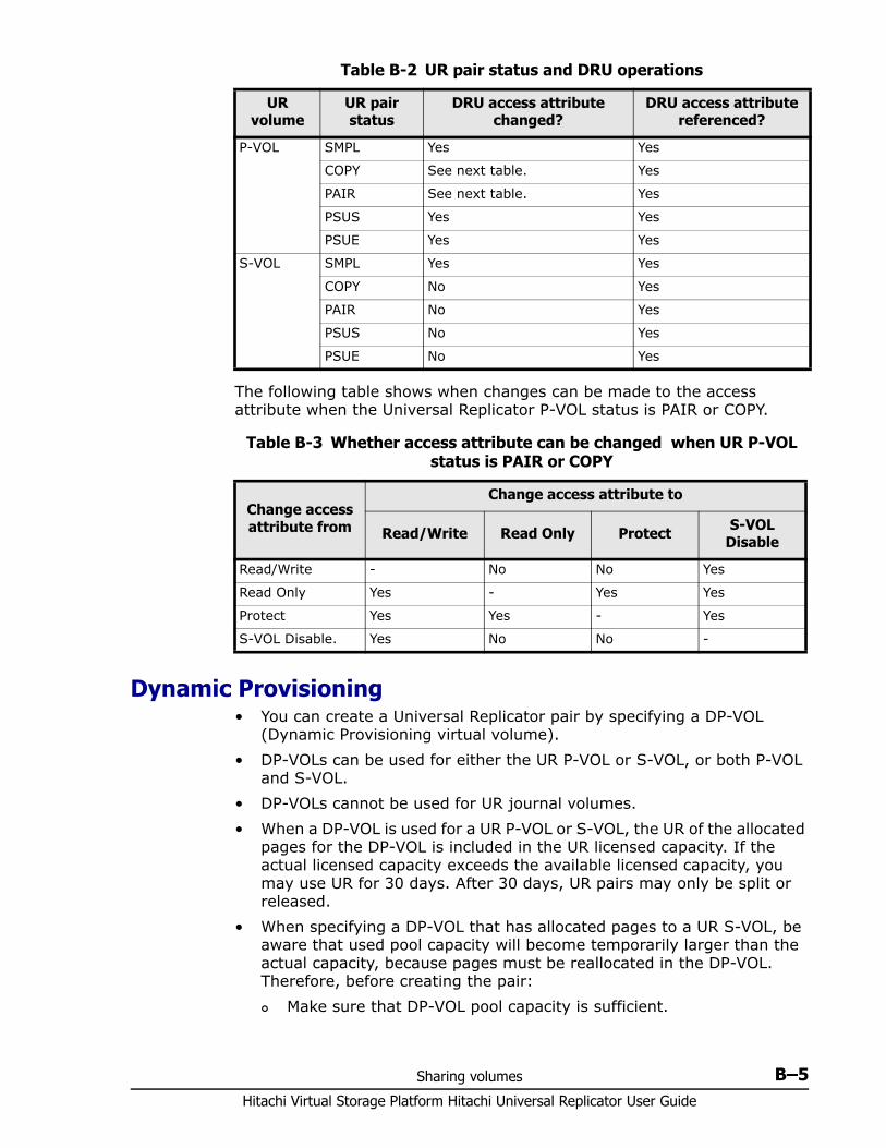
Sharing volumes B–5Hitachi Virtual Storage Platform Hitachi Universal Replicator User Guide
Table B-2 UR pair status and DRU operations
The following table shows when changes can be made to the access attribute when the Universal Replicator P-VOL status is PAIR or COPY.
Table B-3 Whether access attribute can be changed when UR P-VOL status is PAIR or COPY
Dynamic Provisioning• You can create a Universal Replicator pair by specifying a DP-VOL
(Dynamic Provisioning virtual volume).• DP-VOLs can be used for either the UR P-VOL or S-VOL, or both P-VOL
and S-VOL.• DP-VOLs cannot be used for UR journal volumes.• When a DP-VOL is used for a UR P-VOL or S-VOL, the UR of the allocated
pages for the DP-VOL is included in the UR licensed capacity. If the actual licensed capacity exceeds the available licensed capacity, you may use UR for 30 days. After 30 days, UR pairs may only be split or released.
• When specifying a DP-VOL that has allocated pages to a UR S-VOL, be aware that used pool capacity will become temporarily larger than the actual capacity, because pages must be reallocated in the DP-VOL. Therefore, before creating the pair: Make sure that DP-VOL pool capacity is sufficient.
UR volume
UR pair status
DRU access attribute changed?
DRU access attribute referenced?
P-VOL SMPL Yes Yes
COPY See next table. Yes
PAIR See next table. Yes
PSUS Yes Yes
PSUE Yes Yes
S-VOL SMPL Yes Yes
COPY No Yes
PAIR No Yes
PSUS No Yes
PSUE No Yes
Change access attribute from
Change access attribute to
Read/Write Read Only Protect S-VOL Disable
Read/Write - No No Yes
Read Only Yes - Yes Yes
Protect Yes Yes - Yes
S-VOL Disable. Yes No No -
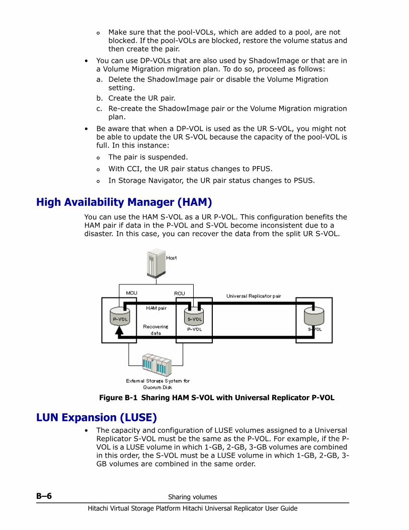
Hitachi Virtual Storage Platform Hitachi Universal Replicator User Guide
B–6 Sharing volumes
Make sure that the pool-VOLs, which are added to a pool, are not blocked. If the pool-VOLs are blocked, restore the volume status and then create the pair.
• You can use DP-VOLs that are also used by ShadowImage or that are in a Volume Migration migration plan. To do so, proceed as follows:a. Delete the ShadowImage pair or disable the Volume Migration
setting.b. Create the UR pair.c. Re-create the ShadowImage pair or the Volume Migration migration
plan.• Be aware that when a DP-VOL is used as the UR S-VOL, you might not
be able to update the UR S-VOL because the capacity of the pool-VOL is full. In this instance: The pair is suspended. With CCI, the UR pair status changes to PFUS. In Storage Navigator, the UR pair status changes to PSUS.
High Availability Manager (HAM) You can use the HAM S-VOL as a UR P-VOL. This configuration benefits the HAM pair if data in the P-VOL and S-VOL become inconsistent due to a disaster. In this case, you can recover the data from the split UR S-VOL.
LUN Expansion (LUSE)• The capacity and configuration of LUSE volumes assigned to a Universal
Replicator S-VOL must be the same as the P-VOL. For example, if the P-VOL is a LUSE volume in which 1-GB, 2-GB, 3-GB volumes are combined in this order, the S-VOL must be a LUSE volume in which 1-GB, 2-GB, 3-GB volumes are combined in the same order.
Figure B-1 Sharing HAM S-VOL with Universal Replicator P-VOL
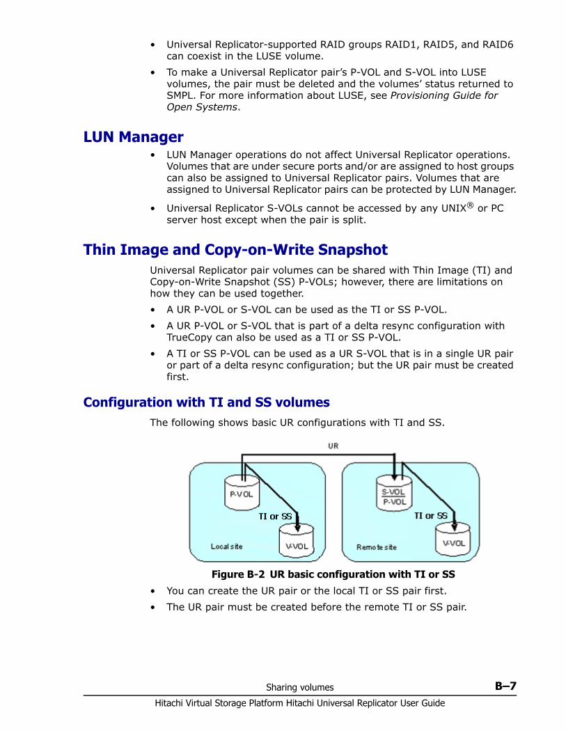
Sharing volumes B–7Hitachi Virtual Storage Platform Hitachi Universal Replicator User Guide
• Universal Replicator-supported RAID groups RAID1, RAID5, and RAID6 can coexist in the LUSE volume.
• To make a Universal Replicator pair’s P-VOL and S-VOL into LUSE volumes, the pair must be deleted and the volumes’ status returned to SMPL. For more information about LUSE, see Provisioning Guide for Open Systems.
LUN Manager• LUN Manager operations do not affect Universal Replicator operations.
Volumes that are under secure ports and/or are assigned to host groups can also be assigned to Universal Replicator pairs. Volumes that are assigned to Universal Replicator pairs can be protected by LUN Manager.
• Universal Replicator S-VOLs cannot be accessed by any UNIX® or PC server host except when the pair is split.
Thin Image and Copy-on-Write SnapshotUniversal Replicator pair volumes can be shared with Thin Image (TI) and Copy-on-Write Snapshot (SS) P-VOLs; however, there are limitations on how they can be used together.• A UR P-VOL or S-VOL can be used as the TI or SS P-VOL.• A UR P-VOL or S-VOL that is part of a delta resync configuration with
TrueCopy can also be used as a TI or SS P-VOL.• A TI or SS P-VOL can be used as a UR S-VOL that is in a single UR pair
or part of a delta resync configuration; but the UR pair must be created first.
Configuration with TI and SS volumesThe following shows basic UR configurations with TI and SS.
• You can create the UR pair or the local TI or SS pair first. • The UR pair must be created before the remote TI or SS pair.
Figure B-2 UR basic configuration with TI or SS
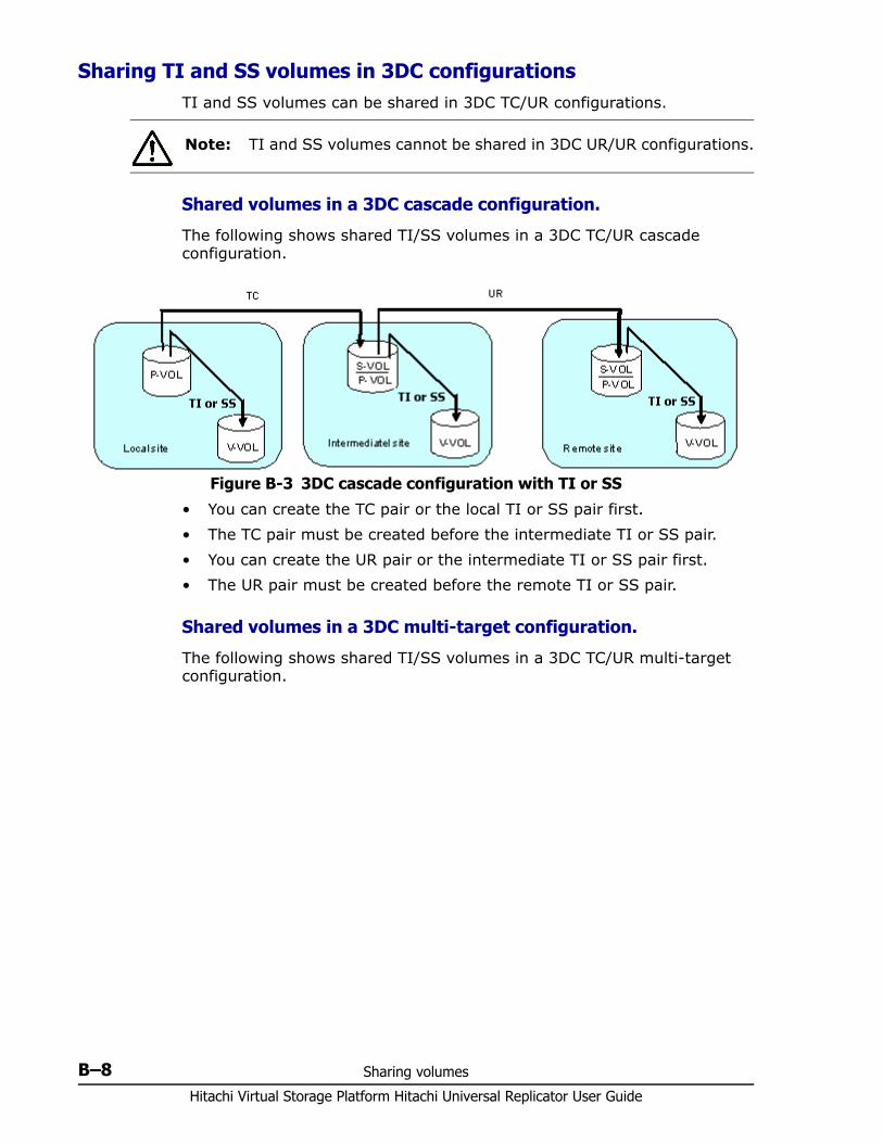
Hitachi Virtual Storage Platform Hitachi Universal Replicator User Guide
B–8 Sharing volumes
Sharing TI and SS volumes in 3DC configurationsTI and SS volumes can be shared in 3DC TC/UR configurations.
Shared volumes in a 3DC cascade configuration.
The following shows shared TI/SS volumes in a 3DC TC/UR cascade configuration.
• You can create the TC pair or the local TI or SS pair first. • The TC pair must be created before the intermediate TI or SS pair.• You can create the UR pair or the intermediate TI or SS pair first. • The UR pair must be created before the remote TI or SS pair.
Shared volumes in a 3DC multi-target configuration.
The following shows shared TI/SS volumes in a 3DC TC/UR multi-target configuration.
Note: TI and SS volumes cannot be shared in 3DC UR/UR configurations.
Figure B-3 3DC cascade configuration with TI or SS
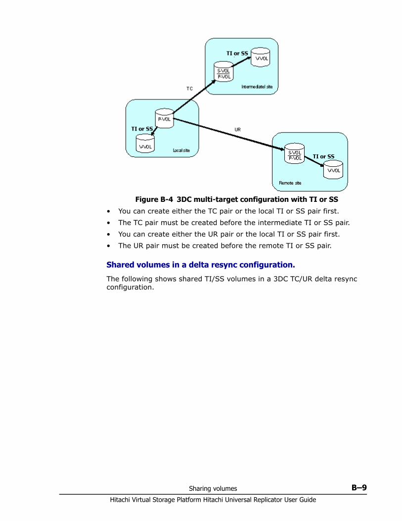
Sharing volumes B–9Hitachi Virtual Storage Platform Hitachi Universal Replicator User Guide
• You can create either the TC pair or the local TI or SS pair first. • The TC pair must be created before the intermediate TI or SS pair.• You can create either the UR pair or the local TI or SS pair first. • The UR pair must be created before the remote TI or SS pair.
Shared volumes in a delta resync configuration.
The following shows shared TI/SS volumes in a 3DC TC/UR delta resync configuration.
Figure B-4 3DC multi-target configuration with TI or SS
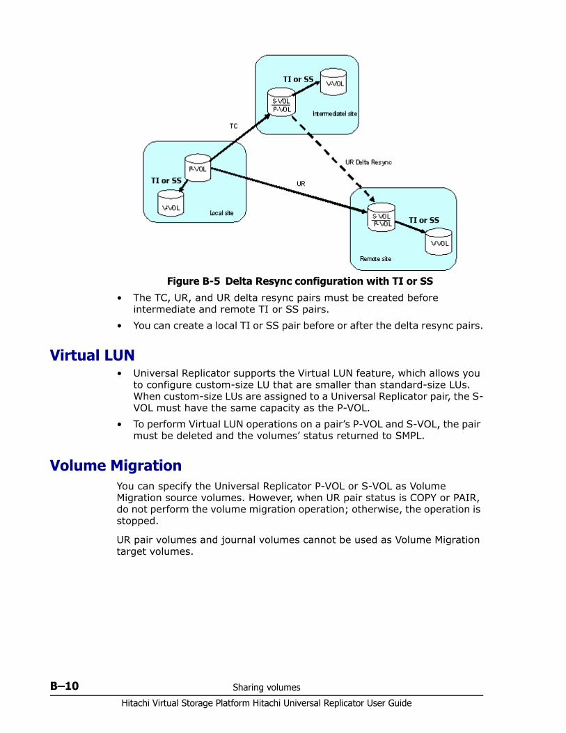
Hitachi Virtual Storage Platform Hitachi Universal Replicator User Guide
B–10 Sharing volumes
• The TC, UR, and UR delta resync pairs must be created before intermediate and remote TI or SS pairs.
• You can create a local TI or SS pair before or after the delta resync pairs.
Virtual LUN • Universal Replicator supports the Virtual LUN feature, which allows you
to configure custom-size LU that are smaller than standard-size LUs. When custom-size LUs are assigned to a Universal Replicator pair, the S-VOL must have the same capacity as the P-VOL.
• To perform Virtual LUN operations on a pair’s P-VOL and S-VOL, the pair must be deleted and the volumes’ status returned to SMPL.
Volume Migration You can specify the Universal Replicator P-VOL or S-VOL as Volume Migration source volumes. However, when UR pair status is COPY or PAIR, do not perform the volume migration operation; otherwise, the operation is stopped.
UR pair volumes and journal volumes cannot be used as Volume Migration target volumes.
Figure B-5 Delta Resync configuration with TI or SS
C
Configurations with TrueCopy C–1Hitachi Virtual Storage Platform Hitachi Universal Replicator User Guide
Configurations with TrueCopy
Universal Replicator and TrueCopy can share the same data volumes. Using Universal Replicator and TrueCopy can extend disaster recovery options to a third data center.
This appendix provides planning and setup information for sharing Universal Replicator volumes with TrueCopy. It describes four Universal Replicator/TrueCopy configurations.
Note that the term “P-VOL” indicates the primary volume, and “S-VOL” indicates the secondary volume. These terms are used for both Universal Replicator (UR) and TrueCopy (TC).
□ Sharing volumes with TrueCopy
□ 3DC cascade configuration
□ 3DC multi-target configuration
□ Delta resync configuration
□ 2 data center configuration
Hitachi Virtual Storage Platform Hitachi Universal Replicator User Guide
C–2 Configurations with TrueCopy
Sharing volumes with TrueCopyLike UR, a TC pair maintains a copy of the production volume in a second location. However, unlike UR, TC’s secondary volume (S-VOL) is synchronous, and the remote system is located within the same general region as the local site.
Creating a UR backup and a TC backup ensures that a copy in a third location is available in the event that the primary site, and possibly one of the secondary sites, fail.
UR and TC can be used and configured in a variety of ways. The following describes four principle configurations. These are covered in detail in this appendix.• In a 3-data-center cascade configuration (3DC cascade), three data
centers are used — the TC production site, the TC/UR intermediate site, and the distant UR remote site. The figure in the 3DC cascade configuration on page C-3 provides an illustration. With this configuration, you can locate the TC synchronous site near the local site to lower I/O response time, while the UR backup provides a disaster recovery solution at a remote site.
• In a 3-data-center multi-target configuration (3DC multi-target), the production volume is shared by the TC and UR. This volume is the primary volume (P-VOL) for both at the local site. The targets of each system are located at different remote sites. They provide the TC solution and the UR asynchronous disaster recovery solution. The TC secondary site is at an intermediate location, the UR secondary site is at a distant location. This is illustrated in 3DC multi-target configuration on page C-4.
• Another use of the 3DC multi-target is the UR Delta Resync pair, which provides a quick way to regain a long distance copy after disaster in the event that the TC/UR P-VOL becomes unusable. In this case, the host continues I/O operations at the intermediate TC S-VOL site. With a second UR pair previously set up between the TC S-VOL and the UR S-VOL, only differential data needs to be copied to the UR S-VOL. Delta resync is illustrated in Delta resync configuration on page C-6.
• In a 2-data-center configuration (2DC), data is copied from the TC P-VOL to an intermediate site, though not to the TC S-VOL. Instead, the data is copied to the UR master journal volume. This results in an asynchronous copy that side-steps the TC S-VOL, and thus enhances overall transfer speed to the UR S-VOL. This is illustrated in 2 data center configuration on page C-15.
Note: Three-data-center (3DC) configurations can also be set up using Universal Replicator at all three sites. See 3 UR data-center configurations on page A-1 for information.
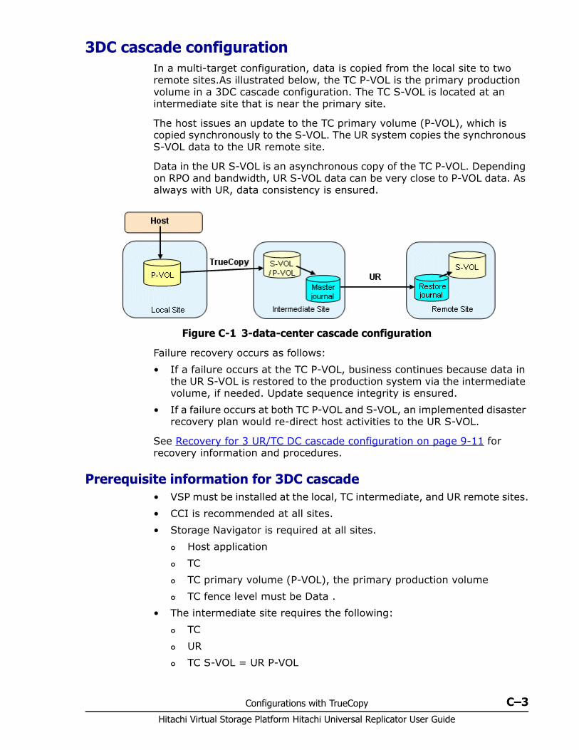
Configurations with TrueCopy C–3Hitachi Virtual Storage Platform Hitachi Universal Replicator User Guide
3DC cascade configuration In a multi-target configuration, data is copied from the local site to two remote sites.As illustrated below, the TC P-VOL is the primary production volume in a 3DC cascade configuration. The TC S-VOL is located at an intermediate site that is near the primary site.
The host issues an update to the TC primary volume (P-VOL), which is copied synchronously to the S-VOL. The UR system copies the synchronous S-VOL data to the UR remote site.
Data in the UR S-VOL is an asynchronous copy of the TC P-VOL. Depending on RPO and bandwidth, UR S-VOL data can be very close to P-VOL data. As always with UR, data consistency is ensured.
Failure recovery occurs as follows:• If a failure occurs at the TC P-VOL, business continues because data in
the UR S-VOL is restored to the production system via the intermediate volume, if needed. Update sequence integrity is ensured.
• If a failure occurs at both TC P-VOL and S-VOL, an implemented disaster recovery plan would re-direct host activities to the UR S-VOL.
See Recovery for 3 UR/TC DC cascade configuration on page 9-11 for recovery information and procedures.
Prerequisite information for 3DC cascade • VSP must be installed at the local, TC intermediate, and UR remote sites.• CCI is recommended at all sites.• Storage Navigator is required at all sites.
Host application TC TC primary volume (P-VOL), the primary production volume TC fence level must be Data .
• The intermediate site requires the following: TC UR TC S-VOL = UR P-VOL
Figure C-1 3-data-center cascade configuration
Hitachi Virtual Storage Platform Hitachi Universal Replicator User Guide
C–4 Configurations with TrueCopy
UR master journal volume• The remote site requires the following:
UR UR S-VOL UR remote journal volume
• Differential data is used to re-synchronize a suspended TC or UR pair.• When the TC pair is recovered, the UR pair in PAIR or COPY status is
automatically split by the system.• The fence level of the TC P-VOL must be Data.• 3DC cascade is not supported for multiple primary and secondary
systems. The UR or TC pair in this configuration would be suspended when the status became PAIR or COPY.
• The response time for host I/Os will be the response time for TC operation plus the creation time of journal data in the intermediate site.
• The utilization rate on the primary site with a 3DC cascade configuration is higher than if UR and a TC systems are used independently.
Procedure for setting up 3DC cascade To set up a 3DC cascade configuration1. Install and set up TC and UR on the required systems. 2. Create the TC pair on the primary system. See Hitachi TrueCopy® User
Guide for instructions.3. When TC pair status is PAIR, create the UR pair on the secondary system
using the TC S-VOL as the UR P-VOL. The UR operation is rejected by the system if TC pair status is not already PAIR.Mirror ID must be set between 1 and 3.
3DC multi-target configuration In a multi-target configuration, data is copied from the local site to two remote sites.As illustrated below, the P-VOL is paired with the TC secondary volume (S-VOL) and the UR S-VOL at separate remote sites in a 3DC multi-target configuration. The TC site is at an intermediate distance; the UR site is located at a greater distance.

Configurations with TrueCopy C–5Hitachi Virtual Storage Platform Hitachi Universal Replicator User Guide
The host issues an update to the production volume and, synchronously, to the TC S-VOL. As with a standalone UR system, the update data is asynchronously written from the primary volume (P-VOL) to the UR S-VOL.
The benefit of this configuration is that it provides a third copy of the data, helping to ensure that business can continue in the event of a failure at the other two sites.
Failure recovery occurs as follows:• If a failure occurs in the P-VOL, business is resumed using the TC S-VOL.
When the failure is corrected at the primary site, business tasks are transferred back to the primary site. In addition, a quick disaster recovery solution can be put in place while the primary site is being restored, using a UR pair for delta resync. In this configuration, the TC S-VOL is paired with the UR S-VOL.See Delta resync configuration on page C-6 for more information.
• If a failure occurs in the TC system (P-VOL and S-VOL), business is resumed using the UR S-VOL. When the failure is corrected, business tasks are transferred back to the primary site.
• If a failure occurs in the UR system (P-VOL and S-VOL), business is resumed using the TC S-VOL.
See Recovery for 3 UR/TC DC multi-target configuration on page 9-11 for recovery information and procedures.
Prerequisite information for 3DC multi-target • VSP must be installed at the local, TC intermediate, and UR remote sites.• CCI is recommended at all sites.• Storage Navigator is required at all sites.• The primary site requires the following:
TC UR
Figure C-2 3-data-center multi-target configuration
Hitachi Virtual Storage Platform Hitachi Universal Replicator User Guide
C–6 Configurations with TrueCopy
TC P-VOL = UR P-VOL. This is the primary production volume. UR master journal volume
• The intermediate site requires the following: TC UR TC S-VOL
• The remote site requires the following: UR UR S-VOL UR remote journal volume
• 3DC multi-target can be used in configurations with multiple primary and secondary systems. However, delta resync configurations are not supported in configurations with multiple primary and secondary systems.
Procedure for setting up 3DC multi-targetTo set up a 3DC multi-target configuration1. Install and set up TC and UR on the required systems. 2. Create a TC pair on the primary system. See Hitachi TrueCopy® User
Guide for instructions.3. When TC pair status is PAIR, create the UR pair on the primary system.
The mirror ID must be set between 1 and 3.
Delta resync configuration In a UR delta resync configuration, you create a second UR pair in a 3DC multi-target. The pair is created using the TC secondary volume (S-VOL) and the UR S-VOL.
The delta resync operation requires less time to bring the S-VOL to a consistent state after a failure occurs because only missing differential data is copied. The delta resync operation is performed when the primary site fails, as illustrated in the figure below.
In addition, you can create or re-create the UR pair for delta resync:• When the UR pair status changes to HOLD after the delta resync
operation.• When you re-create the UR pair for delta resync when recovering the
primary site.
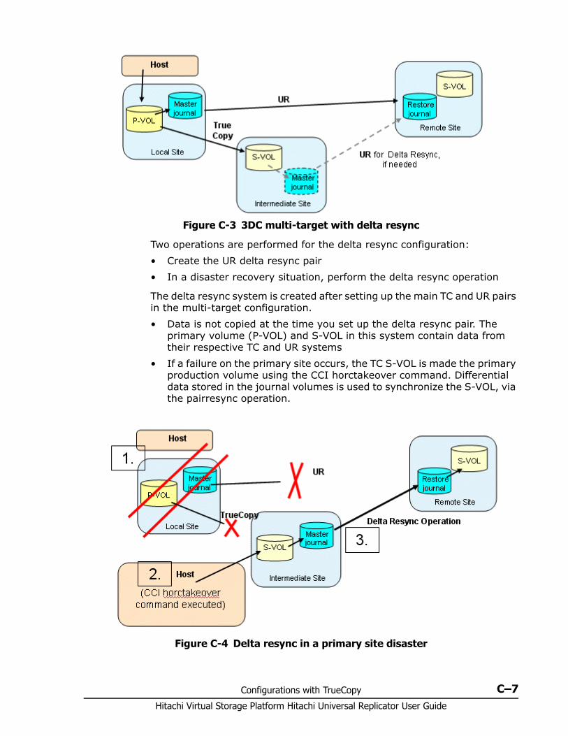
Configurations with TrueCopy C–7Hitachi Virtual Storage Platform Hitachi Universal Replicator User Guide
Two operations are performed for the delta resync configuration:• Create the UR delta resync pair• In a disaster recovery situation, perform the delta resync operation
The delta resync system is created after setting up the main TC and UR pairs in the multi-target configuration.• Data is not copied at the time you set up the delta resync pair. The
primary volume (P-VOL) and S-VOL in this system contain data from their respective TC and UR systems
• If a failure on the primary site occurs, the TC S-VOL is made the primary production volume using the CCI horctakeover command. Differential data stored in the journal volumes is used to synchronize the S-VOL, via the pairresync operation.
Figure C-3 3DC multi-target with delta resync
Figure C-4 Delta resync in a primary site disaster
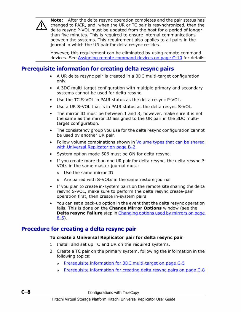
Hitachi Virtual Storage Platform Hitachi Universal Replicator User Guide
C–8 Configurations with TrueCopy
Prerequisite information for creating delta resync pairs • A UR delta resync pair is created in a 3DC multi-target configuration
only.• A 3DC multi-target configuration with multiple primary and secondary
systems cannot be used for delta resync.• Use the TC S-VOL in PAIR status as the delta resync P-VOL.• Use a UR S-VOL that is in PAIR status as the delta resync S-VOL.• The mirror ID must be between 1 and 3; however, make sure it is not
the same as the mirror ID assigned to the UR pair in the 3DC multi-target configuration.
• The consistency group you use for the delta resync configuration cannot be used by another UR pair.
• Follow volume combinations shown in Volume types that can be shared with Universal Replicator on page B-2.
• System option mode 506 must be ON for delta resync.• If you create more than one UR pair for delta resync, the delta resync P-
VOLs in the same master journal must: Use the same mirror ID Are paired with S-VOLs in the same restore journal
• If you plan to create in-system pairs on the remote site sharing the delta resync S-VOL, make sure to perform the delta resync create-pair operation first, then create in-system pairs.
• You can set a back-up option in the event that the delta resync operation fails. This is done on the Change Mirror Options window (see the Delta resync Failure step in Changing options used by mirrors on page 8-5).
Procedure for creating a delta resync pair To create a Universal Replicator pair for delta resync pair1. Install and set up TC and UR on the required systems.2. Create a TC pair on the primary system, following the information in the
following topics: Prerequisite information for 3DC multi-target on page C-5 Prerequisite information for creating delta resync pairs on page C-8
Note: After the delta resync operation completes and the pair status has changed to PAIR, and, when the UR or TC pair is resynchronized, then the delta resync P-VOL must be updated from the host for a period of longer than five minutes. This is required to ensure internal communications between the systems. This requirement also applies to all pairs in the journal in which the UR pair for delta resync resides.
However, this requirement can be eliminated by using remote command devices. See Assigning remote command devices on page C-10 for details.
Configurations with TrueCopy C–9Hitachi Virtual Storage Platform Hitachi Universal Replicator User Guide
3. After the TC pair status is PAIR, create the UR pair on the primary system, following the information in the following topics: Prerequisite information for 3DC multi-target on page C-5 Prerequisite information for creating delta resync pairs on page C-8
4. Create a second UR pair from the TC S-VOL to the UR S-VOL. Specify the Initial Copy option as Delta.
Prerequisite information for delta resync operation You perform the delta resync operation using the Pair Resync operation. After reviewing these prerequisites, see Resynchronizing pairs on page 6-10. • The delta resync P-VOL must be updated for longer than 5 minutes after
the operation is completed and pair status has changed to PAIR. However, a workaround is available that allows you to avoid the 5-minute update requirement. See Assigning remote command devices on page C-10 for details.
• Required pair and volume statuses: The TC volume used as the 3DC multi-target P-VOL: PAIR The TC S-VOL used as the delta resync P-VOL: SSWS.
Check this status after executing the CCI horctakeover command The UR delta resync pair: HOLD or HOLDING. If the pair status is
HLDE, change to HOLD by performing the pairresync operation.This applies to all pairs in the journal in which the UR pair for delta resync resides.
The UR volume used as the 3DC multi-target and the delta resync pair S-VOL and uses two mirror IDs — one for the 3DC multi-target pair and one for the delta resync pair:- 3DC multi-target S-VOL: PAIR, PSUS, or PSUE - Delta resync S-VOL: HOLD.
• If the delta resync S-VOL has been backed up on the remote site using SI, TI, or SS, make sure to review the information for the Delta resync Failure step on the Change Mirror Option window (Changing options used by mirrors on page 8-5).
• Differential data is stored in the master journal but may not be completely present after a failure at the primary site when the pair was being recovered (or after creating the delta resync pair configuration).
• If data in the restore journal exceeds 80% of capacity, old journal data is automatically deleted. This can occur when the suspended pair has not been re-synchronized for a long time.In this case, based on journal option settings, the entire P-VOL is copied to the S-VOL. In a delta resync operation, processing is not performed.
Note: The UR S-VOL uses two mirror IDs because of its dual use in the 3DC multi-target and delta resync configurations. The statuses shown above are required for the two mirrors as well as for the journal in which the UR pair for delta resync resides.
Hitachi Virtual Storage Platform Hitachi Universal Replicator User Guide
C–10 Configurations with TrueCopy
• Journal data may also be destroyed in the following cases: When you restore the TC or UR pair in the multi-target configuration,
then also update the delta resync pair. When retry-processing occurs because of a delay of the P-VOL
update. When the update of a TC S-VOL is delayed.
• The UR pair status in a delta resync configuration could become PSUS or PSUE if you split the pair, or if there is a failure when copying all data from the P-VOL to the S-VOL. If you then run the delta resync operation, all data might be copied from P-VOL to S-VOL regardless of journal option settings.
• If the pair’s mirror is in Halting or Stopping status, the resynchronization command is rejected.
Problems that can occur
Journal data will not exist, and therefore the delta resync operation will fail, in the following cases:• After creating the UR pair, the primary delta resync P-VOL is updated but
not the UR P-VOL.• When the multi-target P-VOL is resynchronized after the TC pair was
split.• When the UR S-VOL is resynchronized after it was split.• When the UR pair is resynchronized after being split and then the journal
volume at the TC secondary site exceeds 70 %.• When the delta resync P-VOL is updated, and then the journal volume
at the TC secondary site exceeds 70%.• When the delta resync pair is created and no volumes (including
volumes after failover or failback) in the primary site are updated.• When the status of the UR pair for delta resync operation becomes
HLDE, the journal data necessary for the delta resync operation might be discarded. In this case, all data in the delta resync P-VOL would be copied to the delta resync S-VOL.
Performing the delta resync operation The delta resync operation is performed during disaster recovery. This operation copies differential data from the TC S-VOL to the UR S-VOL.
The delta resync operation is part of the Pair Resync operation. Follow instructions in Resynchronizing pairs on page 6-10 to execute delta resync.
Assigning remote command devices This section provides a workaround using remote command devices for the delta resync update time-limit.
Configurations with TrueCopy C–11Hitachi Virtual Storage Platform Hitachi Universal Replicator User Guide
When the delta resync operation has been performed and pair status is changed to PAIR, the delta resync P-VOL must be updated from the host for longer than five minutes. This is required to ensure internal communications between the intermediate and remote sites.
However, you can work around this five-minute-plus update requirement by setting up command devices and remote command devices. With remote command devices set up, communications between the two sites is performed automatically, and the delta resync is ready to use when the operation is run.
This requires setting up two command devices and two remote command devices on each site — the local, intermediate, and remote sites — as explained in the following general guidelines. Consult the Hitachi Universal Volume Manager User Guide for more complete information about remote command devices.1. Set up four command devices each on the local, intermediate, and
remote sites.2. Set up and dedicate two external ports and two target ports on each site
for the command/remote command devices. Configure paths between external ports and target ports. For details about the external ports, see Hitachi Universal Volume Manager User Guide. For instructions on setting paths, see Provisioning Guide for Open Systems.
3. On each site, map a command device via a target port to a device on one of the other sites. The device on the other site should be mapped to as a remote command device, using an external port on that system.
4. Repeat the previous step so that two command devices on each site are mapped to a remote command device on each of the other two sites.
Thus:• Each site should have two command devices mapped via two target
ports to the other two sites.• Each site should also have two remote command devices mapped-to via
external ports from the other two sites.
The following illustration shows this command/remote command device configuration.
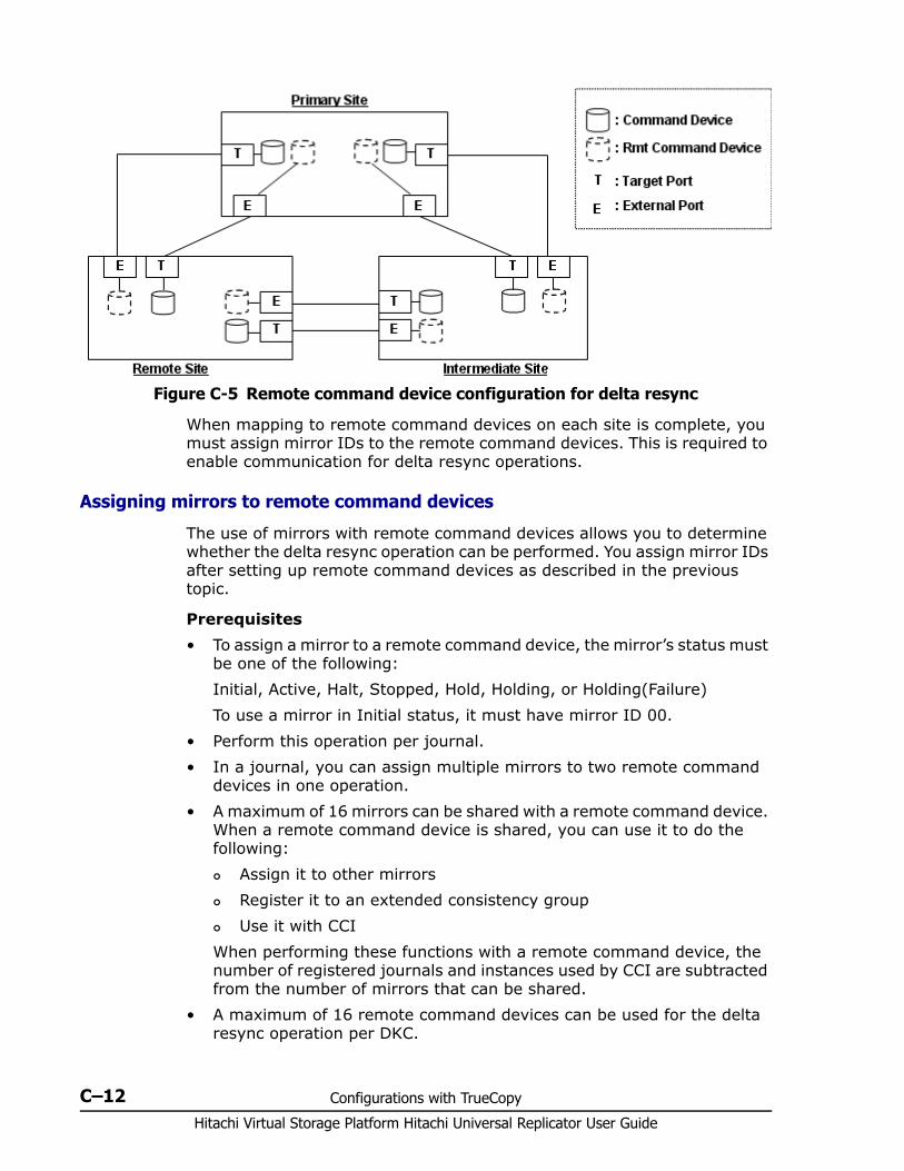
Hitachi Virtual Storage Platform Hitachi Universal Replicator User Guide
C–12 Configurations with TrueCopy
When mapping to remote command devices on each site is complete, you must assign mirror IDs to the remote command devices. This is required to enable communication for delta resync operations.
Assigning mirrors to remote command devices
The use of mirrors with remote command devices allows you to determine whether the delta resync operation can be performed. You assign mirror IDs after setting up remote command devices as described in the previous topic.
Prerequisites• To assign a mirror to a remote command device, the mirror’s status must
be one of the following:Initial, Active, Halt, Stopped, Hold, Holding, or Holding(Failure)To use a mirror in Initial status, it must have mirror ID 00.
• Perform this operation per journal.• In a journal, you can assign multiple mirrors to two remote command
devices in one operation.• A maximum of 16 mirrors can be shared with a remote command device.
When a remote command device is shared, you can use it to do the following: Assign it to other mirrors Register it to an extended consistency group Use it with CCI
When performing these functions with a remote command device, the number of registered journals and instances used by CCI are subtracted from the number of mirrors that can be shared.
• A maximum of 16 remote command devices can be used for the delta resync operation per DKC.
Figure C-5 Remote command device configuration for delta resync
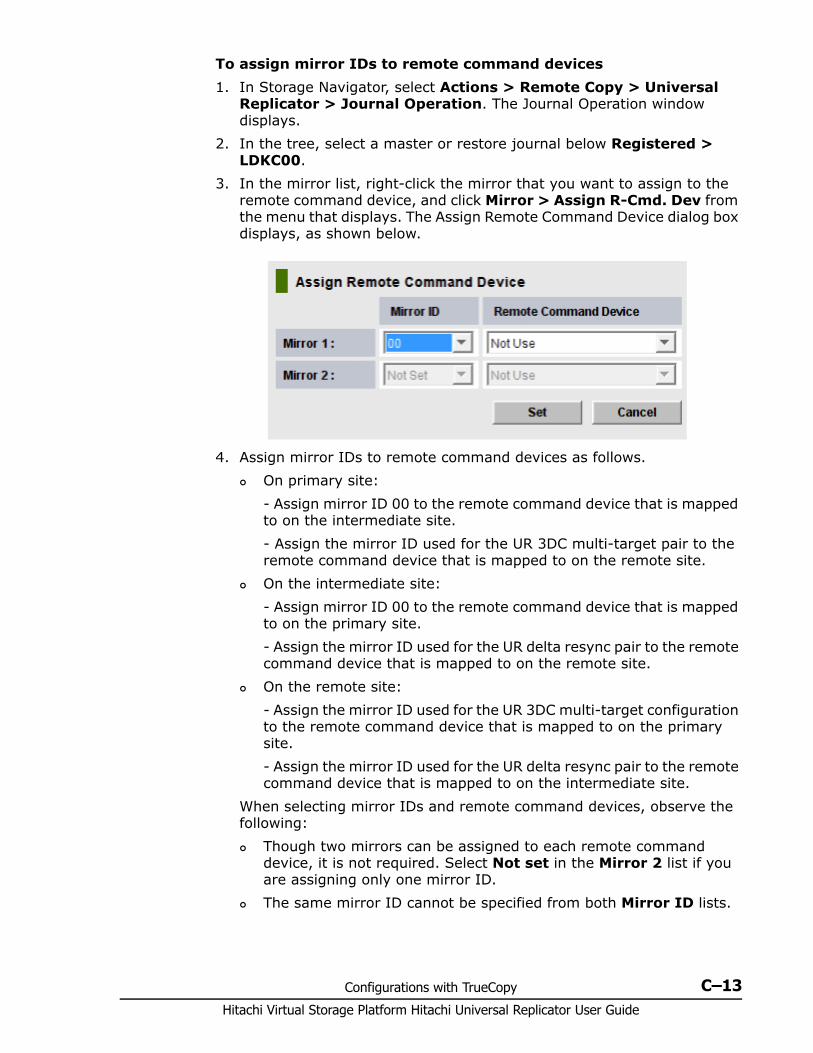
Configurations with TrueCopy C–13Hitachi Virtual Storage Platform Hitachi Universal Replicator User Guide
To assign mirror IDs to remote command devices 1. In Storage Navigator, select Actions > Remote Copy > Universal
Replicator > Journal Operation. The Journal Operation window displays.
2. In the tree, select a master or restore journal below Registered > LDKC00.
3. In the mirror list, right-click the mirror that you want to assign to the remote command device, and click Mirror > Assign R-Cmd. Dev from the menu that displays. The Assign Remote Command Device dialog box displays, as shown below.
4. Assign mirror IDs to remote command devices as follows. On primary site:
- Assign mirror ID 00 to the remote command device that is mapped to on the intermediate site.- Assign the mirror ID used for the UR 3DC multi-target pair to the remote command device that is mapped to on the remote site.
On the intermediate site:- Assign mirror ID 00 to the remote command device that is mapped to on the primary site.- Assign the mirror ID used for the UR delta resync pair to the remote command device that is mapped to on the remote site.
On the remote site:- Assign the mirror ID used for the UR 3DC multi-target configuration to the remote command device that is mapped to on the primary site.- Assign the mirror ID used for the UR delta resync pair to the remote command device that is mapped to on the intermediate site.
When selecting mirror IDs and remote command devices, observe the following: Though two mirrors can be assigned to each remote command
device, it is not required. Select Not set in the Mirror 2 list if you are assigning only one mirror ID.
The same mirror ID cannot be specified from both Mirror ID lists.
Hitachi Virtual Storage Platform Hitachi Universal Replicator User Guide
C–14 Configurations with TrueCopy
If you will not use a remote command device, select Not use in the second (lower) Remote Command Device list.
5. Click Set6. Review your settings in the Preview list in the Journal Operation
window. To modify a setting, right click and select Modify. To cancel a setting, right click and select Cancel.
7. Check the list in the Journal Operation window. If the remote command device is assigned, the LDEV number is displayed in the column of the remote command device.
8. Click Apply to apply the settings. If an error occurs, right click the item in the Preview list and select Error Detail.
You can release a remote command device by selecting Journal > Release R-Cmd. Dev when you right-click the mirror.
Releasing remote command device assigned to a mirror
This operation is performed on the mirror.
To release a remote command device1. Ensure that the Storage Navigator main window is in Modify mode. For
detailed information about how to do this, see Hitachi Storage Navigator User Guide.
2. Ensure that the Journal Operation window is open.3. In the tree, select a master journal or a restore journal from below
Registered > LDKC00.4. From the mirrors, select and right-click the mirror that you want to
release the assigned remote command device.5. Select Mirror > Release R-Cmd Dev on the pop up menu.6. Review your settings in the Preview list in the Journal Operation
window. To modify a setting, right click and select Modify. To cancel a setting, right click and select Delete.
7. Click Apply to release the remote command device from the mirror. If an error occurs, the error code appears in the right-most column of the Preview list. To view detailed information about the error, right click the error code and select Error Detail.See the list in the Journal Operation window whether the remote command device is released from the mirror or not. If the remote command device is not assigned, the column of the remote command device is blank.
Note: A remote command device assigned to a mirror is released automatically when all pairs in a delta resync configuration are deleted.
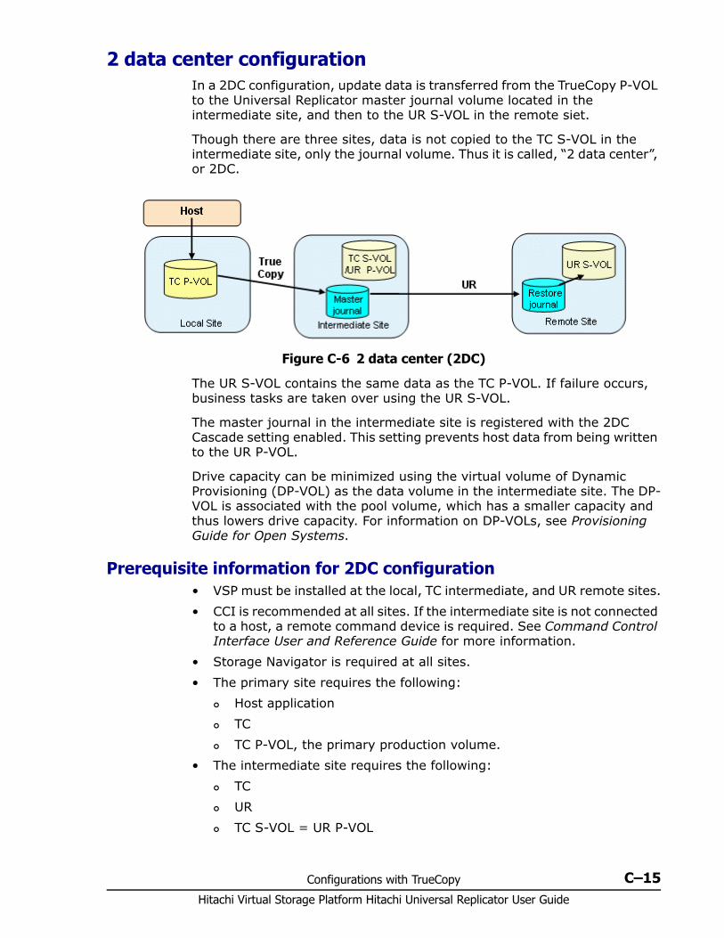
Configurations with TrueCopy C–15Hitachi Virtual Storage Platform Hitachi Universal Replicator User Guide
2 data center configurationIn a 2DC configuration, update data is transferred from the TrueCopy P-VOL to the Universal Replicator master journal volume located in the intermediate site, and then to the UR S-VOL in the remote siet.
Though there are three sites, data is not copied to the TC S-VOL in the intermediate site, only the journal volume. Thus it is called, “2 data center”, or 2DC.
The UR S-VOL contains the same data as the TC P-VOL. If failure occurs, business tasks are taken over using the UR S-VOL.
The master journal in the intermediate site is registered with the 2DC Cascade setting enabled. This setting prevents host data from being written to the UR P-VOL.
Drive capacity can be minimized using the virtual volume of Dynamic Provisioning (DP-VOL) as the data volume in the intermediate site. The DP-VOL is associated with the pool volume, which has a smaller capacity and thus lowers drive capacity. For information on DP-VOLs, see Provisioning Guide for Open Systems.
Prerequisite information for 2DC configuration • VSP must be installed at the local, TC intermediate, and UR remote sites.• CCI is recommended at all sites. If the intermediate site is not connected
to a host, a remote command device is required. See Command Control Interface User and Reference Guide for more information.
• Storage Navigator is required at all sites.• The primary site requires the following:
Host application TC TC P-VOL, the primary production volume.
• The intermediate site requires the following: TC UR TC S-VOL = UR P-VOL
Figure C-6 2 data center (2DC)
Hitachi Virtual Storage Platform Hitachi Universal Replicator User Guide
C–16 Configurations with TrueCopy
UR master journal volume Use a journal that was registered when 2DC Cascade was set to
Enable in the Edit Journal Volumes dialog box. With it you specify whether to write TC P-VOL data to a shared TC S-VOL/UR P-VOL, or to write only to the UR master journal.Enable — Data will be written only to UR master journal volume on the intermediate site for use in the 2DC configuration.Disable — Data will be written to the shared TC S-VOL/UR P-VOL on the intermediate site.
Updates to the TC S-VOL/UR P-VOL is prohibited. System option mode 707 must be set to ON. This allows TC P-VOL
data to be written directly to the UR master journal and not to the shared TC S-VOL/UR P-VOL.- Though it is possible to change option mode 707, the change is not reflected in the system. You need to delete the journal then re-register it with the option mode set to ON.- Storage Navigator does not show system option 707. Therefore, it is recommended that all journals in the system have the same system option mode 707 setting.
• The remote site requires the following: UR UR S-VOL UR remote journal volume
Specifications and restrictions for Universal Replicator pair operations• Because the UR pair depends on the TC pair for data, data copying is not
executed when the UR pair is created, but when the TC pair is created.• About resynchronizing a UR pair:
The TC S-VOL must be in PSUS or PSUE status (Error Level field = Group).
Make sure the UR S-VOL is not in SSWS status when resynchronizing with -swaps or -swapp options.
If the UR pair is suspended and in SSWS status, execute the Pairsplit RB command on the UR S-VOL, confirm that status becomes PSUS, then re-synchronize the pair from the primary site.
• If a UR pair is suspended when the TC S-VOL is in PAIR or COPY status, the TC pair becomes suspended by error.
• A UR pair cannot be released if cascaded with a TC pair. To release a UR pair, first release the TC pair, then release the UR pair.
Specifications and restrictions for TrueCopy pair operations• Specify a volume for the TC P-VOL that is not used in a UR pair In the
2DC configuration, use the journal that was registered when 2DC Cascade was enabled.
Configurations with TrueCopy C–17Hitachi Virtual Storage Platform Hitachi Universal Replicator User Guide
• The UR P-VOL that is specified for the TC S-VOL must be in PAIR status. The only available differential management unit is tracks.
• To re-synchronize the TC pair, the UR P-VOL must be in PAIR status.• You cannot use the takeover command on the TC S-VOL when
suspending the TC pair.• If you release the TC pair when the UR P-VOL is in COPY status, the UR
pair becomes suspended by error.• For UR, an X at the end of the device ID indicates the LDEV is a Dynamic
Provisioning virtual volume. However, the X does not display when both of the following conditions exist: The TC S-VOL is a Dynamic Provisioning virtual volume. The UR S-VOL is not a Dynamic Provisioning virtual volume.
Procedure for a 2DC configuration To set up a 2DC configuration1. Install and set up TC and UR on the required systems.2. When registering the journal on the intermediate site, set 2DC Cascade
to Enable in the Edit Journal Volumes dialog box.3. Create the UR pair on the intermediate system.4. When UR pair status is PAIR, create the TC pair on the primary system.
See Hitachi TrueCopy® User Guide.5. Confirm that TC pair status becomes PAIR.

Hitachi Virtual Storage Platform Hitachi Universal Replicator User Guide
C–18 Configurations with TrueCopy
D
Configurations with ShadowImage D–1Hitachi Virtual Storage Platform Hitachi Universal Replicator User Guide
Configurations with ShadowImage
Universal Replicator and ShadowImage can share the same data volumes to provide multiple copies of data, at both the primary and secondary sites.
This appendix provides configurations and information for using ShadowImage with Universal Replicator. For details about ShadowImage, see the Hitachi ShadowImage® User Guide.
□ Overview
□ Configurations with ShadowImage primary volumes
□ Configurations with ShadowImage secondary volumes
□ Pair status and data currency
Hitachi Virtual Storage Platform Hitachi Universal Replicator User Guide
D–2 Configurations with ShadowImage
OverviewUniversal Replicator’s main function is to maintain a copy of the production volume in a remote location. Backing up the local and/or remote Universal Replicator (UR) volumes with ShadowImage (SI), or backing up the SI volumes with UR, provides additional advantages. • When sharing the primary volume with SI
On-site data backup is provided in case of a UR failure. Multiple copies of production data are provided on the local site for
secondary purposes, such as data analysis, testing and so on.• Sharing the SI secondary volume with the UR primary volume on the
local site provides a remote copy.• When SI is cascaded on the remote side, data in the SI secondary
volume can be used for testing the UR system and for recovery purposes. The SI secondary volume is available for continuous replication
during a test. If a UR problem is encountered during an actual recovery procedure,
the SI secondary volume provides a golden copy of the UR secondary volume, which can be used to restore the UR secondary volume.
UR data volumes are shared with SI volumes in specific configurations. The following topics discuss these supported configurations.
Configurations with ShadowImage primary volumes
An SI primary volume can be shared with a UR primary or secondary volume. • An SI primary volume shared with the UR primary volume is illustrated
below. This configuration allows you to use SI for on-site data backup in case of a UR failure, and to use UR to provide remote backup of the SI primary volume in case of an SI failure.
Note: To split the SI pairs in a consistency group whose volumes are also used in UR pairs, the UR pairs must be in PAIR, PSUS, or PSUE status.
Note: ShadowImage for Mainframe source and target volumes are now referred to in Storage Navigator as “primary” and “secondary” volumes. However, if using the previous version of the GUI, “source volume (S-VOL)” and “target volume (T-VOL)” are still used. Terms in this document correspond to the current GUI terminology.

Configurations with ShadowImage D–3Hitachi Virtual Storage Platform Hitachi Universal Replicator User Guide
• A UR secondary volume shared with the SI primary volume is illustrated below. With this configuration, multiple backup copies of the UR primary volume can be made on the secondary system.
• UR primary and secondary volumes shared with SI primary volumes is illustrated below. This configuration provides multiple copies of the source volume at the local and remote sites.
Figure D-1 Shared UR and SI primary volume
Caution: When you share a UR S-VOL with an SI P-VOL as shown in the following figure, the restore operation to the UR S-VOL takes time. This is especially the case when the SI pair is in the PSUS(SP)/PSUS status because of the time needed to copy the SI pair.
Because of the extra time that may be needed, make sure the UR journal volume is sized with enough capacity to handle the possible increase in I/O. If journal volume capacity is insufficient, the pair will suspend because of failure.
Figure D-2 Shared UR S-VOL and SI primary volume
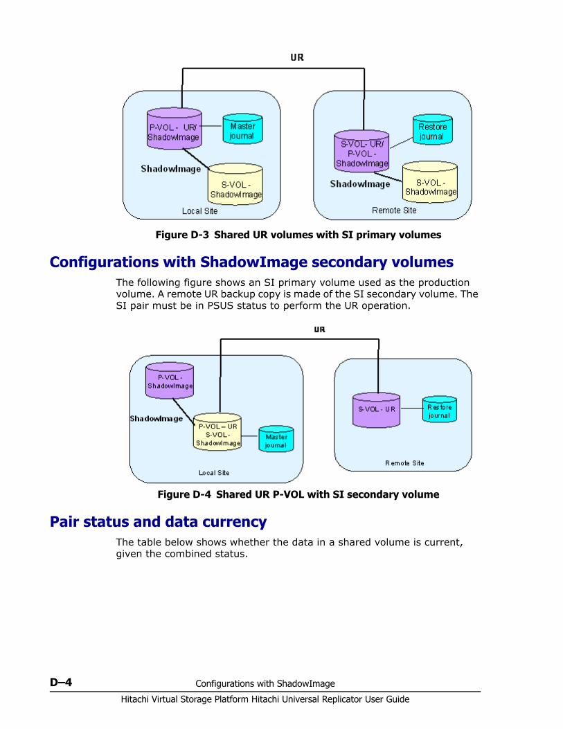
Hitachi Virtual Storage Platform Hitachi Universal Replicator User Guide
D–4 Configurations with ShadowImage
Configurations with ShadowImage secondary volumes The following figure shows an SI primary volume used as the production volume. A remote UR backup copy is made of the SI secondary volume. The SI pair must be in PSUS status to perform the UR operation.
Pair status and data currencyThe table below shows whether the data in a shared volume is current, given the combined status.
Figure D-3 Shared UR volumes with SI primary volumes
Figure D-4 Shared UR P-VOL with SI secondary volume
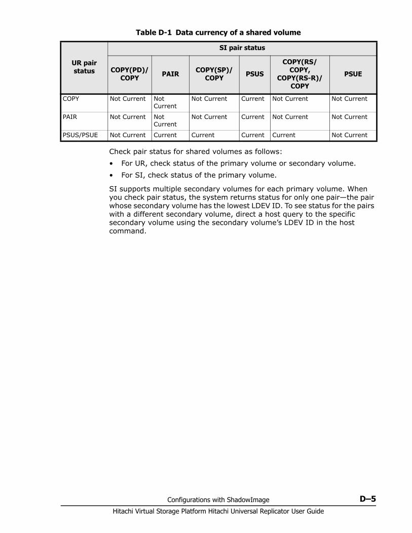
Configurations with ShadowImage D–5Hitachi Virtual Storage Platform Hitachi Universal Replicator User Guide
Table D-1 Data currency of a shared volume
Check pair status for shared volumes as follows:• For UR, check status of the primary volume or secondary volume.• For SI, check status of the primary volume.
SI supports multiple secondary volumes for each primary volume. When you check pair status, the system returns status for only one pair—the pair whose secondary volume has the lowest LDEV ID. To see status for the pairs with a different secondary volume, direct a host query to the specific secondary volume using the secondary volume’s LDEV ID in the host command.
UR pair status
SI pair status
COPY(PD)/COPY PAIR COPY(SP)/
COPY PSUS
COPY(RS/COPY,
COPY(RS-R)/COPY
PSUE
COPY Not Current Not Current
Not Current Current Not Current Not Current
PAIR Not Current Not Current
Not Current Current Not Current Not Current
PSUS/PSUE Not Current Current Current Current Current Not Current

Hitachi Virtual Storage Platform Hitachi Universal Replicator User Guide
D–6 Configurations with ShadowImage
E
GUI reference E–1Hitachi Virtual Storage Platform Hitachi Universal Replicator User Guide
GUI reference
This appendix describes the Universal Replicator windows, dialog boxes, fields, and behaviors.
□ Journal Operation window
□ Journal Detail window
□ Change Journal Option dialog box
□ Change Mirror Option dialog box
□ Edit Journal Volumes dialog box
□ Pair Operation window
□ DKC Operation window
□ Usage Monitor window
□ History window
□ Optional Operation window
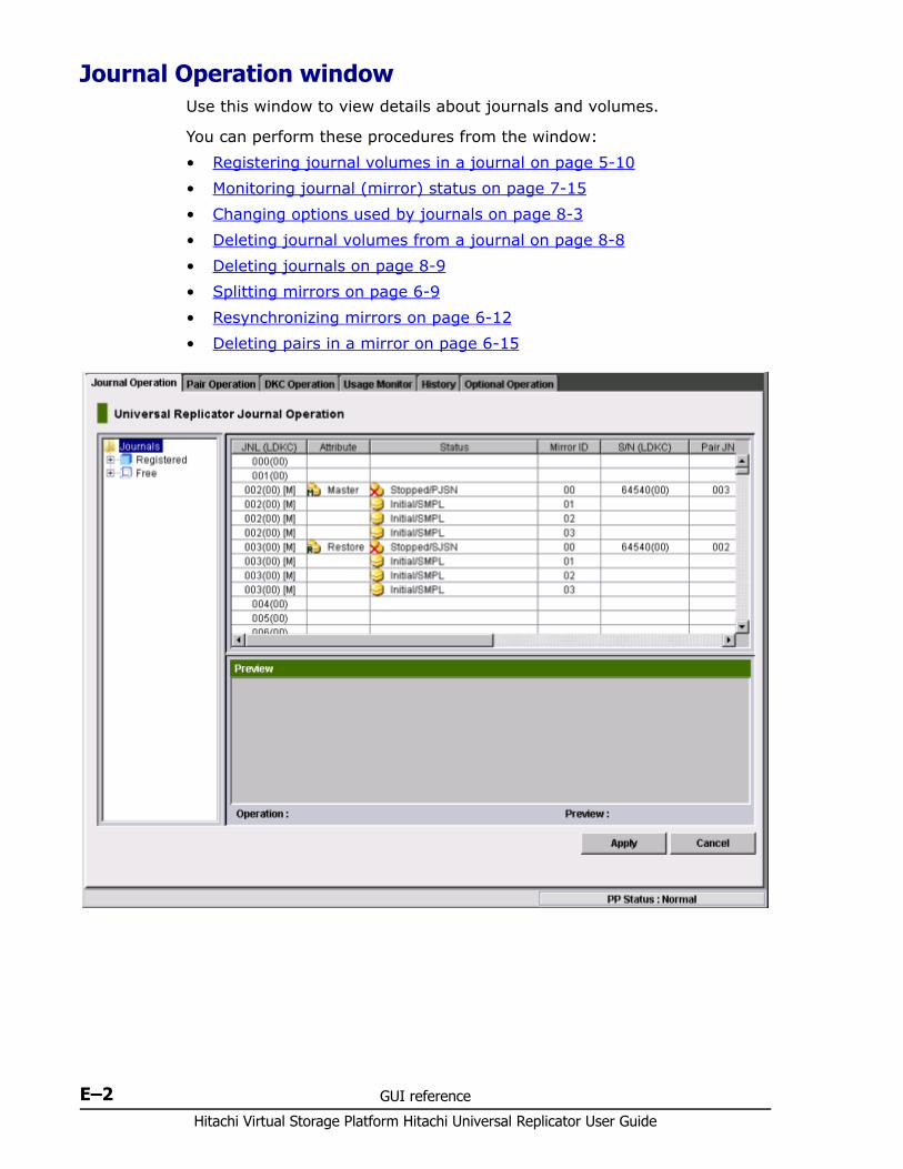
Hitachi Virtual Storage Platform Hitachi Universal Replicator User Guide
E–2 GUI reference
Journal Operation window Use this window to view details about journals and volumes.
You can perform these procedures from the window:• Registering journal volumes in a journal on page 5-10• Monitoring journal (mirror) status on page 7-15• Changing options used by journals on page 8-3• Deleting journal volumes from a journal on page 8-8• Deleting journals on page 8-9• Splitting mirrors on page 6-9• Resynchronizing mirrors on page 6-12• Deleting pairs in a mirror on page 6-15
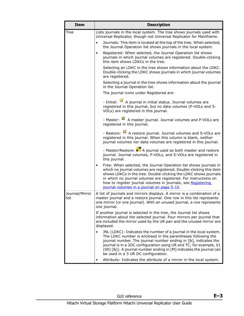
GUI reference E–3Hitachi Virtual Storage Platform Hitachi Universal Replicator User Guide
Item Description
Tree Lists journals in the local system. The tree shows journals used with Universal Replicator, though not Universal Replicator for Mainframe.• Journals: This item is located at the top of the tree. When selected,
the Journal Operation list shows journals in the local system.• Registered: When selected, the Journal Operation list shows
journals in which journal volumes are registered. Double-clicking this item shows LDKCs in the tree.Selecting an LDKC in the tree shows information about the LDKC. Double-clicking the LDKC shows journals in which journal volumes are registered. Selecting a journal in the tree shows information about the journal in the Journal Operation list.The journal icons under Registered are:
- Initial: A journal in initial status. Journal volumes are registered in this journal, but no data volumes (P-VOLs and S-VOLs) are registered in this journal.
- Master: A master journal. Journal volumes and P-VOLs are registered in this journal.
- Restore: A restore journal. Journal volumes and S-VOLs are registered in this journal. When this column is blank, neither journal volumes nor data volumes are registered in this journal.
- Master/Restore: A journal used as both master and restore journal. Journal volumes, P-VOLs, and S-VOLs are registered in this journal.
• Free: When selected, the Journal Operation list shows journals in which no journal volumes are registered. Double-clicking this item shows LDKCs in the tree. Double-clicking the LDKC shows journals in which no journal volumes are registered. For instructions on how to register journal volumes in journals, see Registering journal volumes in a journal on page 5-10.
Journal/Mirror list
A list of journals and mirrors displays. A mirror is a combination of a master journal and a restore journal. One row in this list represents one mirror (or one journal). With an unused journal, a row represents one journal.If another journal is selected in the tree, the Journal list shows information about the selected journal. Four mirrors per journal that are included the mirror used by the UR pair and the unused mirror are displayed.• JNL (LDKC): Indicates the number of a journal in the local system.
The LDKC number is enclosed in the parentheses following the journal number. The journal number ending in [&], indicates the journal is in a 2DC configuration using UR and TC; for example, 01 (00) [&]). A journal number ending in [M] indicates the journal can be used in a 3 UR DC configuration.
• Attribute: Indicates the attribute of a mirror in the local system.
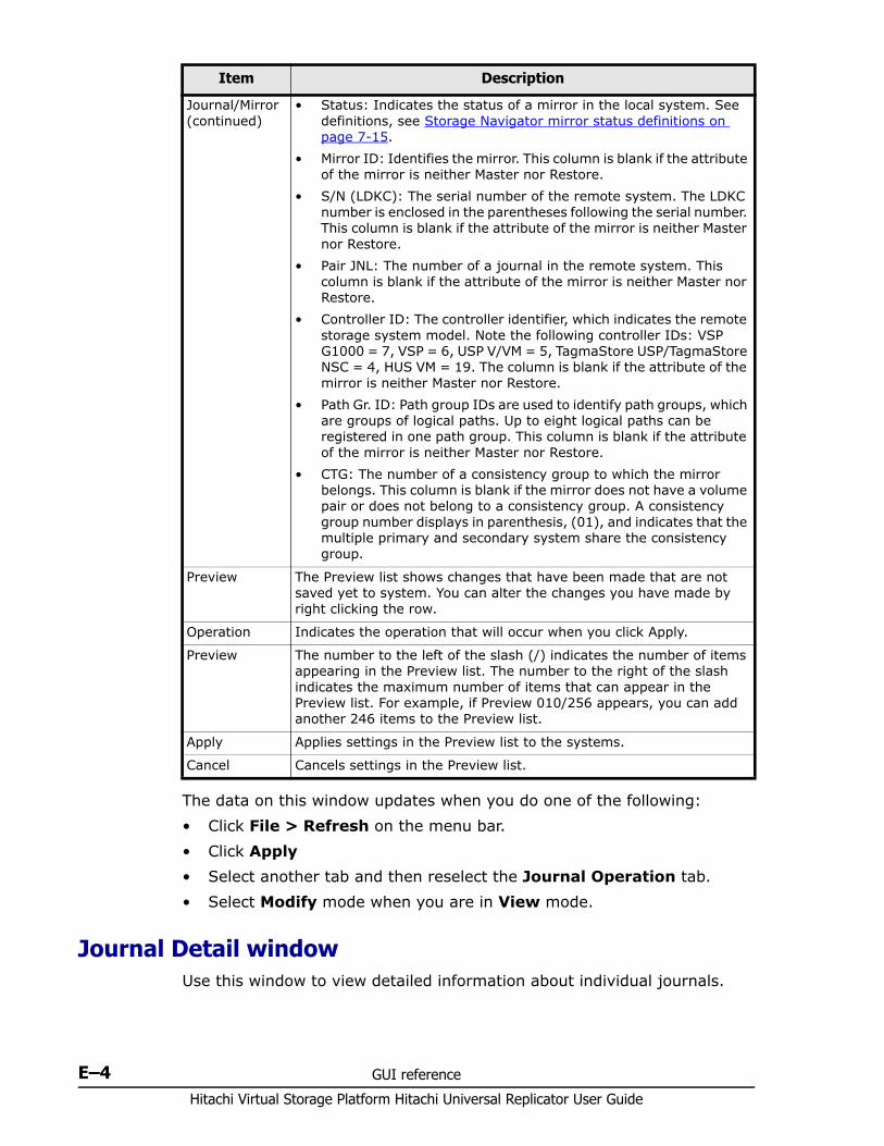
Hitachi Virtual Storage Platform Hitachi Universal Replicator User Guide
E–4 GUI reference
The data on this window updates when you do one of the following:• Click File > Refresh on the menu bar.• Click Apply• Select another tab and then reselect the Journal Operation tab.• Select Modify mode when you are in View mode.
Journal Detail window Use this window to view detailed information about individual journals.
Journal/Mirror (continued)
• Status: Indicates the status of a mirror in the local system. See definitions, see Storage Navigator mirror status definitions on page 7-15.
• Mirror ID: Identifies the mirror. This column is blank if the attribute of the mirror is neither Master nor Restore.
• S/N (LDKC): The serial number of the remote system. The LDKC number is enclosed in the parentheses following the serial number. This column is blank if the attribute of the mirror is neither Master nor Restore.
• Pair JNL: The number of a journal in the remote system. This column is blank if the attribute of the mirror is neither Master nor Restore.
• Controller ID: The controller identifier, which indicates the remote storage system model. Note the following controller IDs: VSP G1000 = 7, VSP = 6, USP V/VM = 5, TagmaStore USP/TagmaStore NSC = 4, HUS VM = 19. The column is blank if the attribute of the mirror is neither Master nor Restore.
• Path Gr. ID: Path group IDs are used to identify path groups, which are groups of logical paths. Up to eight logical paths can be registered in one path group. This column is blank if the attribute of the mirror is neither Master nor Restore.
• CTG: The number of a consistency group to which the mirror belongs. This column is blank if the mirror does not have a volume pair or does not belong to a consistency group. A consistency group number displays in parenthesis, (01), and indicates that the multiple primary and secondary system share the consistency group.
Preview The Preview list shows changes that have been made that are not saved yet to system. You can alter the changes you have made by right clicking the row.
Operation Indicates the operation that will occur when you click Apply.
Preview The number to the left of the slash (/) indicates the number of items appearing in the Preview list. The number to the right of the slash indicates the maximum number of items that can appear in the Preview list. For example, if Preview 010/256 appears, you can add another 246 items to the Preview list.
Apply Applies settings in the Preview list to the systems.
Cancel Cancels settings in the Preview list.
Item Description
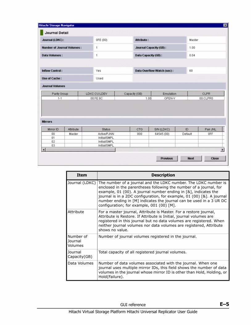
GUI reference E–5Hitachi Virtual Storage Platform Hitachi Universal Replicator User Guide
Item Description
Journal (LDKC) The number of a journal and the LDKC number. The LDKC number is enclosed in the parentheses following the number of a journal, for example, 01 (00). A journal number ending in [&], indicates the journal is in a 2DC configuration, for example, 01 (00) [&]. A journal number ending in [M] indicates the journal can be used in a 3 UR DC configuration; for example, 001 (00) [M].
Attribute For a master journal, Attribute is Master. For a restore journal, Attribute is Restore. If Attribute is Initial, journal volumes are registered in this journal but no data volumes are registered. When neither journal volumes nor data volumes are registered, Attribute shows no value.
Number of Journal Volumes
Number of journal volumes registered in the journal.
Journal Capacity(GB)
Total capacity of all registered journal volumes.
Data Volumes Number of data volumes associated with the journal. When one journal uses multiple mirror IDs, this field shows the number of data volumes in the journal whose mirror ID is other than Hold, Holding, or Hold(Failure).

Hitachi Virtual Storage Platform Hitachi Universal Replicator User Guide
E–6 GUI reference
Data Capacity(GB)
Total capacity of all data volumes. When one journal uses multiple mirror IDs, this field shows the total capacity of the data volumes in the journal whose mirror ID is other than Hold, Holding, or Hold(Failure).
Inflow Control Restrict inflow of update data to the journal volume. Yes restricts inflow, No does not restrict. (slows delay response to hosts).
Data Overflow Watch(sec)
Sets number of seconds for the system to monitor write data to the journal volume, after the journal volume threshold (80%) is reached. Data Overflow Watch is blank when Inflow Control is No. For additional information, see Changing options used by journals on page 8-3.
Use of Cache Whether journal data in the restore journal can be stored in the cache.Used: Journal data will be stored in cache. When there is insufficient space in cache, journal data is also stored in the journal volume. This setting only takes effect on the journal volumes of RAID-5 or RAID-6. For external volumes, or non RAID-5 or RAID-6 journal volumes Not Used is the only setting possible.- Not Used: Journal data is not stored in cache. Caution: This setting does not effect master journals unless the CCI horctakeover command is used to change a master journal to a restore journal.
Journal Volumes
Shows a list of registered journal volumes.- Parity Group: The parity group where a journal volume belongs.- LDKC:CU:LDEV: The LDKC number, the CU number and the LDEV number of a journal volume.- Capacity: The capacity of a journal volume in gigabytes.- Emulation: The emulation type of a journal volume.- CLPR: The number and the name of the CLPR where the journal volume belongs. Journal volumes and data volumes in the same journal can belong to different CLPRs. Journal volumes must belong to the same CLPR. A primary journal and the corresponding secondary journal need not belong to the same CLPR.
Item Description
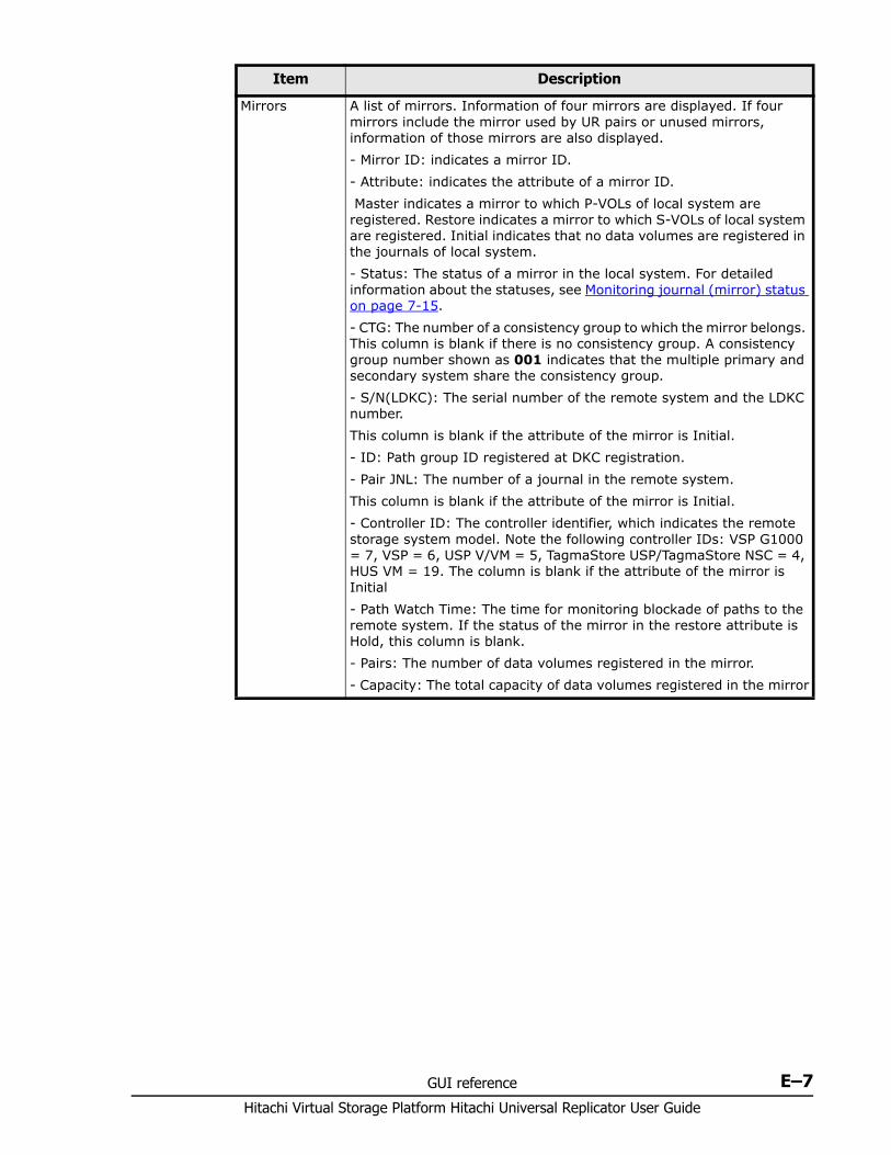
GUI reference E–7Hitachi Virtual Storage Platform Hitachi Universal Replicator User Guide
Mirrors A list of mirrors. Information of four mirrors are displayed. If four mirrors include the mirror used by UR pairs or unused mirrors, information of those mirrors are also displayed. - Mirror ID: indicates a mirror ID.- Attribute: indicates the attribute of a mirror ID. Master indicates a mirror to which P-VOLs of local system are registered. Restore indicates a mirror to which S-VOLs of local system are registered. Initial indicates that no data volumes are registered in the journals of local system.- Status: The status of a mirror in the local system. For detailed information about the statuses, see Monitoring journal (mirror) status on page 7-15.- CTG: The number of a consistency group to which the mirror belongs. This column is blank if there is no consistency group. A consistency group number shown as 001 indicates that the multiple primary and secondary system share the consistency group.- S/N(LDKC): The serial number of the remote system and the LDKC number.This column is blank if the attribute of the mirror is Initial.- ID: Path group ID registered at DKC registration.- Pair JNL: The number of a journal in the remote system.This column is blank if the attribute of the mirror is Initial.- Controller ID: The controller identifier, which indicates the remote storage system model. Note the following controller IDs: VSP G1000 = 7, VSP = 6, USP V/VM = 5, TagmaStore USP/TagmaStore NSC = 4, HUS VM = 19. The column is blank if the attribute of the mirror is Initial- Path Watch Time: The time for monitoring blockade of paths to the remote system. If the status of the mirror in the restore attribute is Hold, this column is blank.- Pairs: The number of data volumes registered in the mirror.- Capacity: The total capacity of data volumes registered in the mirror
Item Description
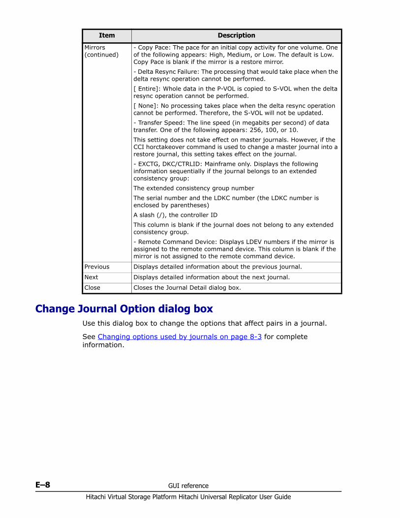
Hitachi Virtual Storage Platform Hitachi Universal Replicator User Guide
E–8 GUI reference
Change Journal Option dialog box Use this dialog box to change the options that affect pairs in a journal.
See Changing options used by journals on page 8-3 for complete information.
Mirrors (continued)
- Copy Pace: The pace for an initial copy activity for one volume. One of the following appears: High, Medium, or Low. The default is Low. Copy Pace is blank if the mirror is a restore mirror.- Delta Resync Failure: The processing that would take place when the delta resync operation cannot be performed.[ Entire]: Whole data in the P-VOL is copied to S-VOL when the delta resync operation cannot be performed.[ None]: No processing takes place when the delta resync operation cannot be performed. Therefore, the S-VOL will not be updated.- Transfer Speed: The line speed (in megabits per second) of data transfer. One of the following appears: 256, 100, or 10.This setting does not take effect on master journals. However, if the CCI horctakeover command is used to change a master journal into a restore journal, this setting takes effect on the journal.- EXCTG, DKC/CTRLID: Mainframe only. Displays the following information sequentially if the journal belongs to an extended consistency group:The extended consistency group numberThe serial number and the LDKC number (the LDKC number is enclosed by parentheses)A slash (/), the controller IDThis column is blank if the journal does not belong to any extended consistency group.- Remote Command Device: Displays LDEV numbers if the mirror is assigned to the remote command device. This column is blank if the mirror is not assigned to the remote command device.
Previous Displays detailed information about the previous journal.
Next Displays detailed information about the next journal.
Close Closes the Journal Detail dialog box.
Item Description
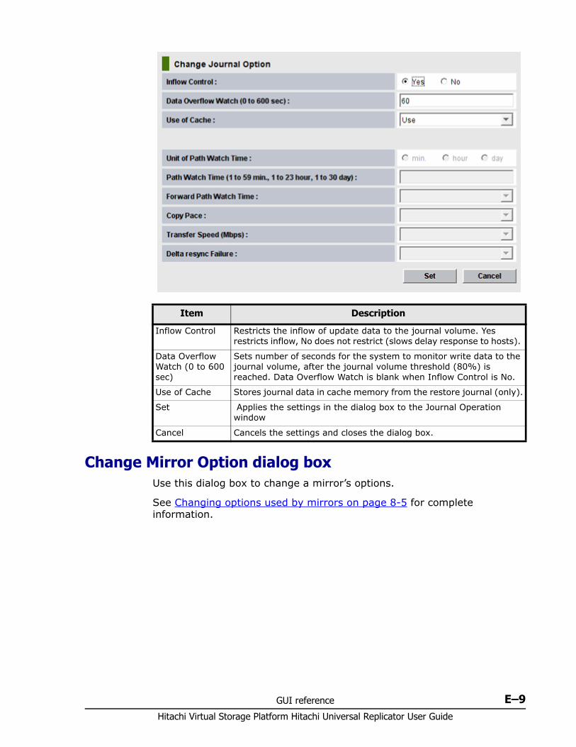
GUI reference E–9Hitachi Virtual Storage Platform Hitachi Universal Replicator User Guide
Change Mirror Option dialog box Use this dialog box to change a mirror’s options.
See Changing options used by mirrors on page 8-5 for complete information.
Item Description
Inflow Control Restricts the inflow of update data to the journal volume. Yes restricts inflow, No does not restrict (slows delay response to hosts).
Data Overflow Watch (0 to 600 sec)
Sets number of seconds for the system to monitor write data to the journal volume, after the journal volume threshold (80%) is reached. Data Overflow Watch is blank when Inflow Control is No.
Use of Cache Stores journal data in cache memory from the restore journal (only).
Set Applies the settings in the dialog box to the Journal Operation window
Cancel Cancels the settings and closes the dialog box.
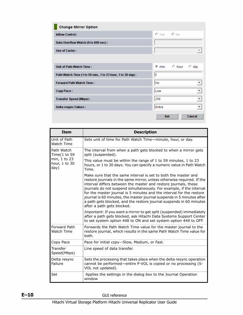
Hitachi Virtual Storage Platform Hitachi Universal Replicator User Guide
E–10 GUI reference
Item Description
Unit of Path Watch Time
Sets unit of time for Path Watch Time—minute, hour, or day.
Path Watch Time(1 to 59 min, 1 to 23 hour, 1 to 30 day)
The interval from when a path gets blocked to when a mirror gets split (suspended).This value must be within the range of 1 to 59 minutes, 1 to 23 hours, or 1 to 30 days. You can specify a numeric value in Path Watch Time. Make sure that the same interval is set to both the master and restore journals in the same mirror, unless otherwise required. If the interval differs between the master and restore journals, these journals do not suspend simultaneously. For example, if the interval for the master journal is 5 minutes and the interval for the restore journal is 60 minutes, the master journal suspends in 5 minutes after a path gets blocked, and the restore journal suspends in 60 minutes after a path gets blocked.Important: If you want a mirror to get split (suspended) immediately after a path gets blocked, ask Hitachi Data Systems Support Center to set system option 448 to ON and set system option 449 to OFF.
Forward Path Watch Time
Forwards the Path Watch Time value for the master journal to the restore journal, which results in the same Path Watch Time value for both.
Copy Pace Pace for initial copy—Slow, Medium, or Fast.
Transfer Speed(Mbps)
Line speed of data transfer.
Delta resync Failure
Sets the processing that takes place when the delta resync operation cannot be performed—entire P-VOL is copied or no processing (S-VOL not updated).
Set Applies the settings in the dialog box to the Journal Operation window
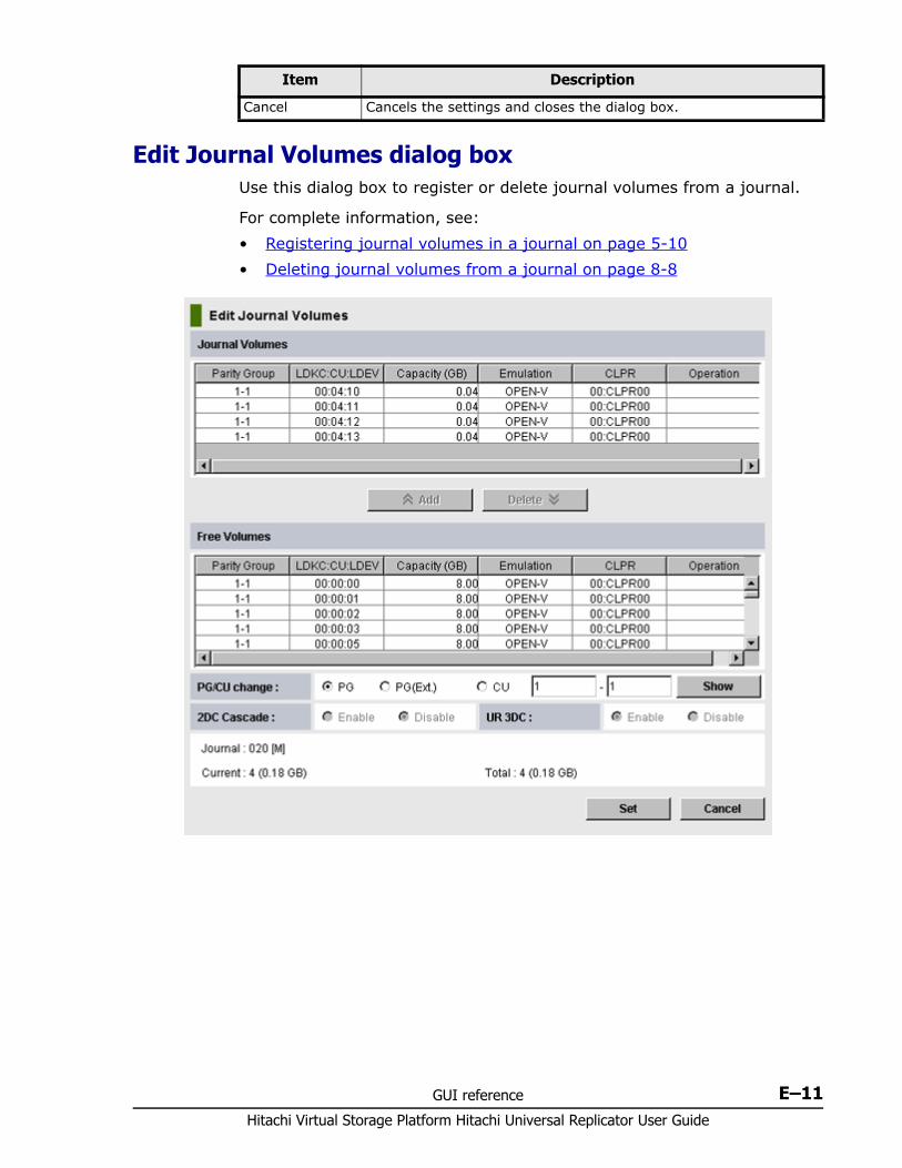
GUI reference E–11Hitachi Virtual Storage Platform Hitachi Universal Replicator User Guide
Edit Journal Volumes dialog boxUse this dialog box to register or delete journal volumes from a journal.
For complete information, see:• Registering journal volumes in a journal on page 5-10• Deleting journal volumes from a journal on page 8-8
Cancel Cancels the settings and closes the dialog box.
Item Description
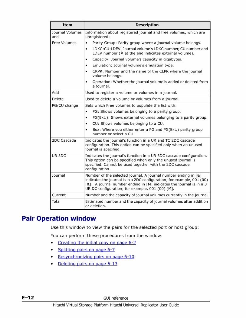
Hitachi Virtual Storage Platform Hitachi Universal Replicator User Guide
E–12 GUI reference
Pair Operation window Use this window to view the pairs for the selected port or host group:
You can perform these procedures from the window:• Creating the initial copy on page 6-2• Splitting pairs on page 6-7• Resynchronizing pairs on page 6-10• Deleting pairs on page 6-13
Item Description
Journal Volumes andFree Volumes
Information about registered journal and free volumes, which are unregistered: • Parity Group: Parity group where a journal volume belongs.• LDKC:CU:LDEV: Journal volume’s LDKC number, CU number and
LDEV number (# at the end indicates external volume).• Capacity: Journal volume’s capacity in gigabytes.• Emulation: Journal volume’s emulation type.• CKPR: Number and the name of the CLPR where the journal
volume belongs.• Operation: Whether the journal volume is added or deleted from
a journal.
Add Used to register a volume or volumes in a journal.
Delete Used to delete a volume or volumes from a journal.
PG/CU change Sets which Free volumes to populate the list with:• PG: Shows volumes belonging to a parity group.• PG(Ext.): Shows external volumes belonging to a parity group.• CU: Shows volumes belonging to a CU.• Box: Where you either enter a PG and PG(Ext.) parity group
number or select a CU.
2DC Cascade Indicates the journal’s function in a UR and TC 2DC cascade configuration. This option can be specified only when an unused journal is specified.
UR 3DC Indicates the journal’s function in a UR 3DC cascade configuration. This option can be specified when only the unused journal is specified. Cannot be used together with the 2DC cascade configuration.
Journal Number of the selected journal. A journal number ending in [&] indicates the journal is in a 2DC configuration; for example, 001 (00) [&]. A journal number ending in [M] indicates the journal is in a 3 UR DC configuration; for example, 001 (00) [M].
Current Number and the capacity of journal volumes currently in the journal.
Total Estimated number and the capacity of journal volumes after addition or deletion.
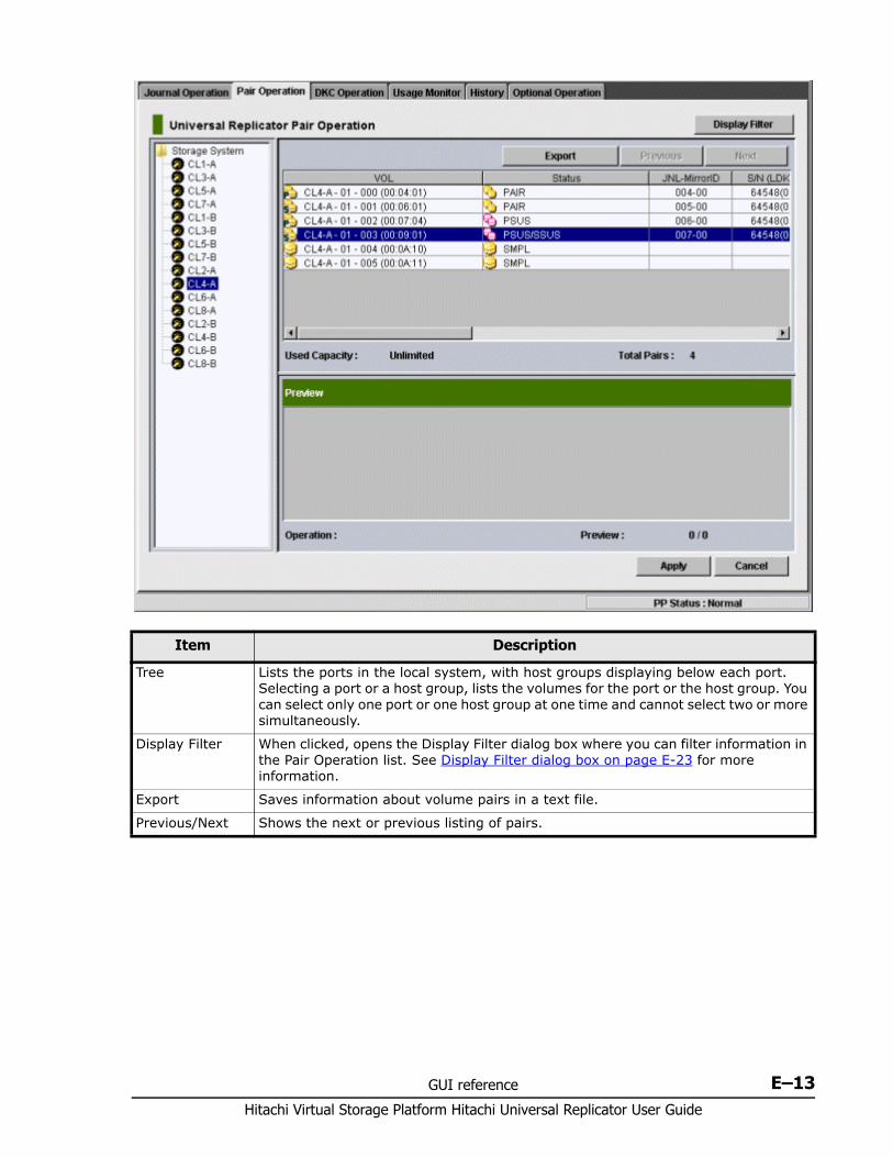
GUI reference E–13Hitachi Virtual Storage Platform Hitachi Universal Replicator User Guide
Item Description
Tree Lists the ports in the local system, with host groups displaying below each port. Selecting a port or a host group, lists the volumes for the port or the host group. You can select only one port or one host group at one time and cannot select two or more simultaneously.
Display Filter When clicked, opens the Display Filter dialog box where you can filter information in the Pair Operation list. See Display Filter dialog box on page E-23 for more information.
Export Saves information about volume pairs in a text file.
Previous/Next Shows the next or previous listing of pairs.
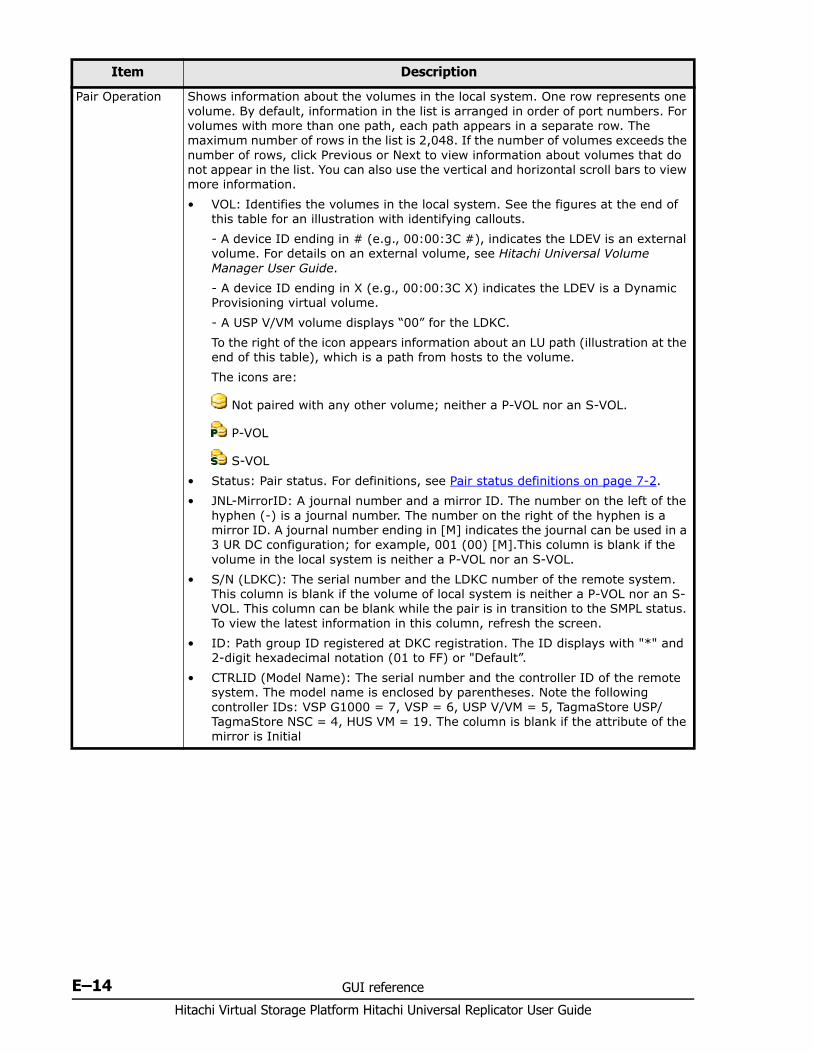
Hitachi Virtual Storage Platform Hitachi Universal Replicator User Guide
E–14 GUI reference
Pair Operation Shows information about the volumes in the local system. One row represents one volume. By default, information in the list is arranged in order of port numbers. For volumes with more than one path, each path appears in a separate row. The maximum number of rows in the list is 2,048. If the number of volumes exceeds the number of rows, click Previous or Next to view information about volumes that do not appear in the list. You can also use the vertical and horizontal scroll bars to view more information.• VOL: Identifies the volumes in the local system. See the figures at the end of
this table for an illustration with identifying callouts. - A device ID ending in # (e.g., 00:00:3C #), indicates the LDEV is an external volume. For details on an external volume, see Hitachi Universal Volume Manager User Guide.- A device ID ending in X (e.g., 00:00:3C X) indicates the LDEV is a Dynamic Provisioning virtual volume.- A USP V/VM volume displays “00” for the LDKC.To the right of the icon appears information about an LU path (illustration at the end of this table), which is a path from hosts to the volume. The icons are:
Not paired with any other volume; neither a P-VOL nor an S-VOL.
P-VOL
S-VOL• Status: Pair status. For definitions, see Pair status definitions on page 7-2.• JNL-MirrorID: A journal number and a mirror ID. The number on the left of the
hyphen (-) is a journal number. The number on the right of the hyphen is a mirror ID. A journal number ending in [M] indicates the journal can be used in a 3 UR DC configuration; for example, 001 (00) [M].This column is blank if the volume in the local system is neither a P-VOL nor an S-VOL.
• S/N (LDKC): The serial number and the LDKC number of the remote system. This column is blank if the volume of local system is neither a P-VOL nor an S-VOL. This column can be blank while the pair is in transition to the SMPL status. To view the latest information in this column, refresh the screen.
• ID: Path group ID registered at DKC registration. The ID displays with "*" and 2-digit hexadecimal notation (01 to FF) or "Default”.
• CTRLID (Model Name): The serial number and the controller ID of the remote system. The model name is enclosed by parentheses. Note the following controller IDs: VSP G1000 = 7, VSP = 6, USP V/VM = 5, TagmaStore USP/TagmaStore NSC = 4, HUS VM = 19. The column is blank if the attribute of the mirror is Initial
Item Description
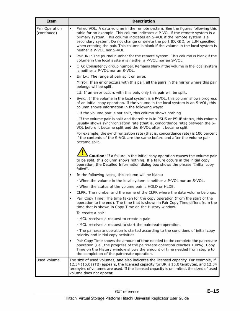
GUI reference E–15Hitachi Virtual Storage Platform Hitachi Universal Replicator User Guide
Pair Operation (continued)
• Paired VOL: A data volume in the remote system. See the figures following this table for an example. This column indicates a P-VOL if the remote system is a primary system. This column indicates an S-VOL if the remote system is a secondary system. Do not change or delete the port ID, GID, or LUN specified when creating the pair. This column is blank if the volume in the local system is neither a P-VOL nor S-VOL
• Pair JNL: The journal number for the remote system. This column is blank if the volume in the local system is neither a P-VOL nor an S-VOL.
• CTG: Consistency group number. Remains blank if the volume in the local system is neither a P-VOL nor an S-VOL.
• Err Lv.: The range of pair split on error.Mirror: If an error occurs with this pair, all the pairs in the mirror where this pair belongs will be split.LU: If an error occurs with this pair, only this pair will be split.
• Sync.: If the volume in the local system is a P-VOL, this column shows progress of an initial copy operation. If the volume in the local system is an S-VOL, this column shows information in the following ways:- If the volume pair is not split, this column shows nothing.- If the volume pair is split and therefore is in PSUS or PSUE status, this column usually shows synchronization rate (that is, concordance rate) between the S-VOL before it became split and the S-VOL after it became split. For example, the synchronization rate (that is, concordance rate) is 100 percent if the contents of the S-VOL are the same before and after the volume pair became split.
Caution: If a failure in the initial copy operation causes the volume pair to be split, this column shows nothing. If a failure occurs in the initial copy operation, the Detailed Information dialog box shows the phrase "Initial copy failed".
• In the following cases, this column will be blank:- When the volume in the local system is neither a P-VOL nor an S-VOL.- When the status of the volume pair is HOLD or HLDE.
• CLPR: The number and the name of the CLPR where the data volume belongs.• Pair Copy Time: The time taken for the copy operation (from the start of the
operation to the end). The time that is shown in Pair Copy Time differs from the time that is shown in Copy Time on the History window.To create a pair:- MCU receives a request to create a pair.- MCU receives a request to start the paircreate operation.- The paircreate operation is started according to the conditions of initial copy priority and initial copy activities.
• Pair Copy Time shows the amount of time needed to the complete the paircreate operation (i.e., the progress of the paircreate operation reaches 100%). Copy Time on the History window shows the amount of time needed from step a to the completion of the paircreate operation.
Used Volume The size of used volumes, and also indicates the licensed capacity. For example, if 12.34 (15.0) (TB) appears, the licensed capacity for UR is 15.0 terabytes, and 12.34 terabytes of volumes are used. If the licensed capacity is unlimited, the sized of used volume does not appear.
Item Description
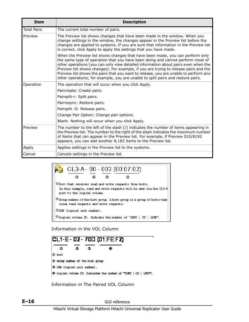
Hitachi Virtual Storage Platform Hitachi Universal Replicator User Guide
E–16 GUI reference
Information in the VOL Column
Information in The Paired VOL Column
Total Pairs The current total number of pairs.
Preview The Preview list shows changes that have been made in the window. When you change settings in the window, the changes appear in the Preview list before the changes are applied to systems. If you are sure that information in the Preview list is correct, click Apply to apply the settings that you have made.When the Preview list shows changes that have been made, you can perform only the same type of operation that you have been doing and cannot perform most of other operations (you can only view detailed information about pairs even when the Preview list shows changes). For example, if you are trying to release pairs and the Preview list shows the pairs that you want to release, you are unable to perform any other operations; for example, you are unable to split pairs and restore pairs.
Operation The operation that will occur when you click Apply.Paircreate: Create pairs.Pairsplit-r: Split pairs.Pairresync: Restore pairs.Pairsplit -S: Release pairs.Change Pair Option: Change pair options.Blank: Nothing will occur when you click Apply.
Preview The number to the left of the slash (/) indicates the number of items appearing in the Preview list. The number to the right of the slash indicates the maximum number of items that can appear in the Preview list. For example, if Preview 010/8192 appears, you can add another 8,182 items to the Preview list.
Apply Applies settings in the Preview list to the systems.
Cancel Cancels settings in the Preview list.
Item Description
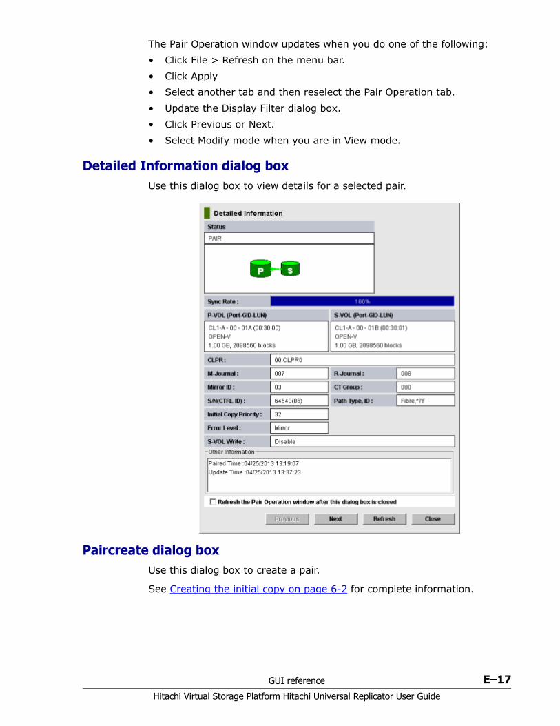
GUI reference E–17Hitachi Virtual Storage Platform Hitachi Universal Replicator User Guide
The Pair Operation window updates when you do one of the following:• Click File > Refresh on the menu bar.• Click Apply• Select another tab and then reselect the Pair Operation tab.• Update the Display Filter dialog box.• Click Previous or Next.• Select Modify mode when you are in View mode.
Detailed Information dialog box Use this dialog box to view details for a selected pair.
Paircreate dialog box Use this dialog box to create a pair.
See Creating the initial copy on page 6-2 for complete information.
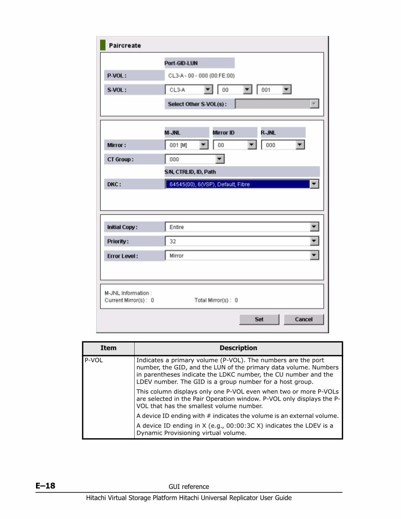
Hitachi Virtual Storage Platform Hitachi Universal Replicator User Guide
E–18 GUI reference
Item Description
P-VOL Indicates a primary volume (P-VOL). The numbers are the port number, the GID, and the LUN of the primary data volume. Numbers in parentheses indicate the LDKC number, the CU number and the LDEV number. The GID is a group number for a host group.This column displays only one P-VOL even when two or more P-VOLs are selected in the Pair Operation window. P-VOL only displays the P-VOL that has the smallest volume number.A device ID ending with # indicates the volume is an external volume. A device ID ending in X (e.g., 00:00:3C X) indicates the LDEV is a Dynamic Provisioning virtual volume.
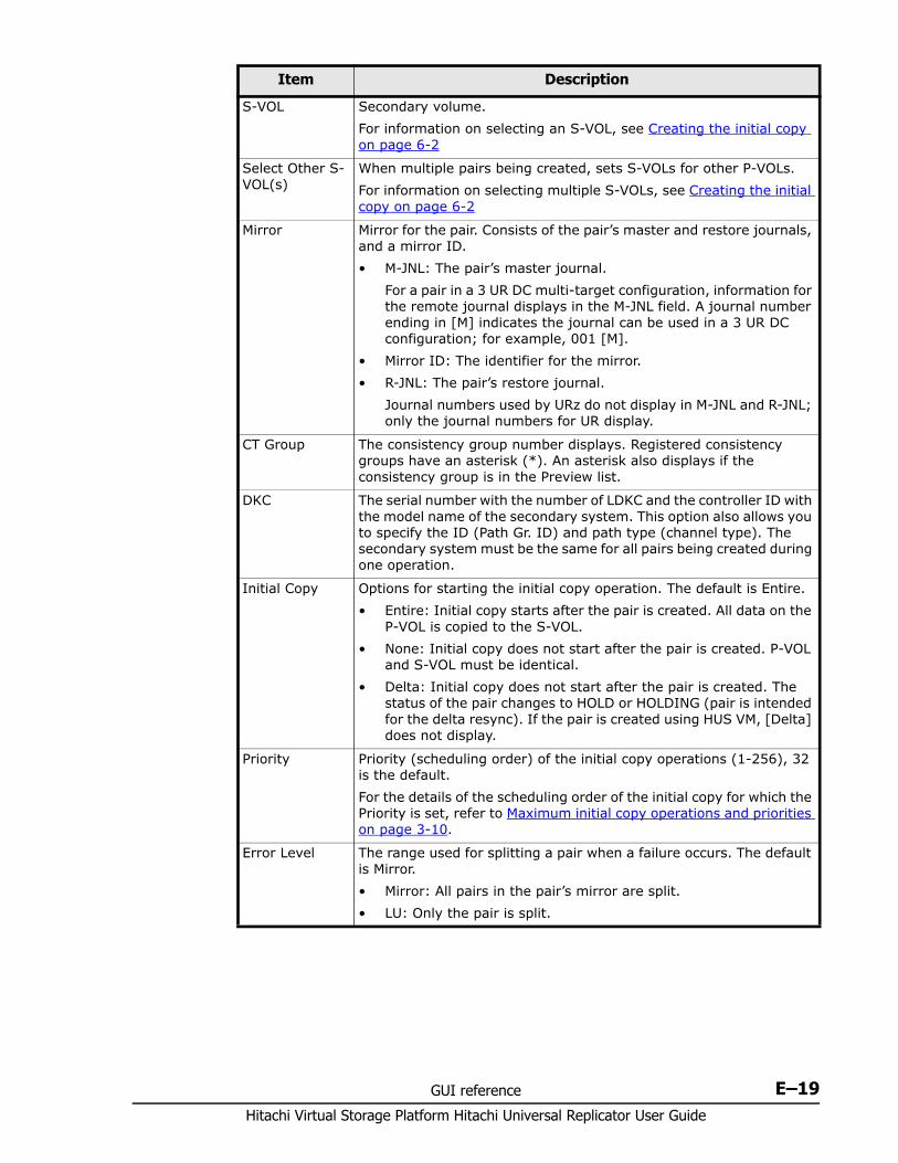
GUI reference E–19Hitachi Virtual Storage Platform Hitachi Universal Replicator User Guide
S-VOL Secondary volume. For information on selecting an S-VOL, see Creating the initial copy on page 6-2
Select Other S-VOL(s)
When multiple pairs being created, sets S-VOLs for other P-VOLs. For information on selecting multiple S-VOLs, see Creating the initial copy on page 6-2
Mirror Mirror for the pair. Consists of the pair’s master and restore journals, and a mirror ID.• M-JNL: The pair’s master journal.
For a pair in a 3 UR DC multi-target configuration, information for the remote journal displays in the M-JNL field. A journal number ending in [M] indicates the journal can be used in a 3 UR DC configuration; for example, 001 [M].
• Mirror ID: The identifier for the mirror.• R-JNL: The pair’s restore journal.
Journal numbers used by URz do not display in M-JNL and R-JNL; only the journal numbers for UR display.
CT Group The consistency group number displays. Registered consistency groups have an asterisk (*). An asterisk also displays if the consistency group is in the Preview list.
DKC The serial number with the number of LDKC and the controller ID with the model name of the secondary system. This option also allows you to specify the ID (Path Gr. ID) and path type (channel type). The secondary system must be the same for all pairs being created during one operation.
Initial Copy Options for starting the initial copy operation. The default is Entire.• Entire: Initial copy starts after the pair is created. All data on the
P-VOL is copied to the S-VOL.• None: Initial copy does not start after the pair is created. P-VOL
and S-VOL must be identical.• Delta: Initial copy does not start after the pair is created. The
status of the pair changes to HOLD or HOLDING (pair is intended for the delta resync). If the pair is created using HUS VM, [Delta] does not display.
Priority Priority (scheduling order) of the initial copy operations (1-256), 32 is the default.For the details of the scheduling order of the initial copy for which the Priority is set, refer to Maximum initial copy operations and priorities on page 3-10.
Error Level The range used for splitting a pair when a failure occurs. The default is Mirror.• Mirror: All pairs in the pair’s mirror are split.• LU: Only the pair is split.
Item Description
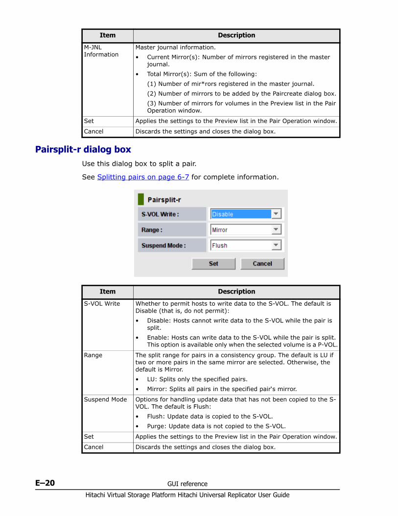
Hitachi Virtual Storage Platform Hitachi Universal Replicator User Guide
E–20 GUI reference
Pairsplit-r dialog box Use this dialog box to split a pair.
See Splitting pairs on page 6-7 for complete information.
M-JNL Information
Master journal information.• Current Mirror(s): Number of mirrors registered in the master
journal.• Total Mirror(s): Sum of the following:
(1) Number of mir*rors registered in the master journal.(2) Number of mirrors to be added by the Paircreate dialog box.(3) Number of mirrors for volumes in the Preview list in the Pair Operation window.
Set Applies the settings to the Preview list in the Pair Operation window.
Cancel Discards the settings and closes the dialog box.
Item Description
Item Description
S-VOL Write Whether to permit hosts to write data to the S-VOL. The default is Disable (that is, do not permit):• Disable: Hosts cannot write data to the S-VOL while the pair is
split.• Enable: Hosts can write data to the S-VOL while the pair is split.
This option is available only when the selected volume is a P-VOL.
Range The split range for pairs in a consistency group. The default is LU if two or more pairs in the same mirror are selected. Otherwise, the default is Mirror.• LU: Splits only the specified pairs. • Mirror: Splits all pairs in the specified pair‘s mirror.
Suspend Mode Options for handling update data that has not been copied to the S-VOL. The default is Flush:• Flush: Update data is copied to the S-VOL. • Purge: Update data is not copied to the S-VOL.
Set Applies the settings to the Preview list in the Pair Operation window.
Cancel Discards the settings and closes the dialog box.
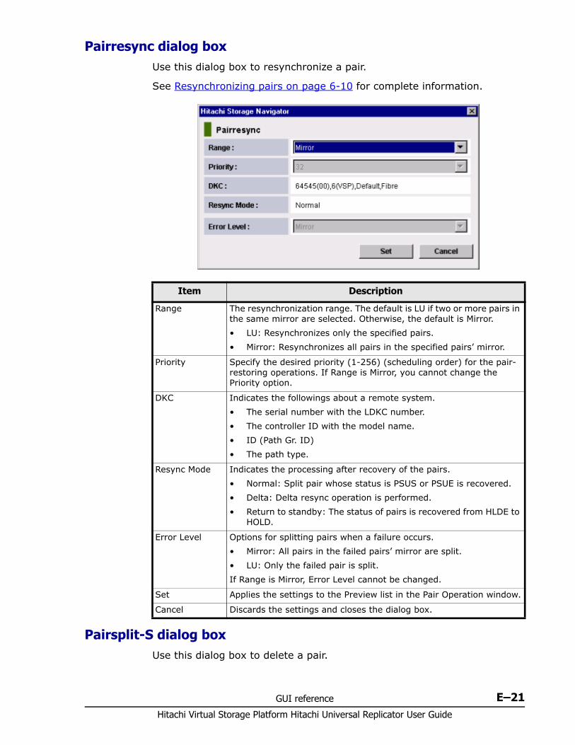
GUI reference E–21Hitachi Virtual Storage Platform Hitachi Universal Replicator User Guide
Pairresync dialog box Use this dialog box to resynchronize a pair.
See Resynchronizing pairs on page 6-10 for complete information.
Pairsplit-S dialog box Use this dialog box to delete a pair.
Item Description
Range The resynchronization range. The default is LU if two or more pairs in the same mirror are selected. Otherwise, the default is Mirror.• LU: Resynchronizes only the specified pairs. • Mirror: Resynchronizes all pairs in the specified pairs’ mirror.
Priority Specify the desired priority (1-256) (scheduling order) for the pair-restoring operations. If Range is Mirror, you cannot change the Priority option.
DKC Indicates the followings about a remote system.• The serial number with the LDKC number.• The controller ID with the model name.• ID (Path Gr. ID)• The path type.
Resync Mode Indicates the processing after recovery of the pairs.• Normal: Split pair whose status is PSUS or PSUE is recovered.• Delta: Delta resync operation is performed. • Return to standby: The status of pairs is recovered from HLDE to
HOLD.
Error Level Options for splitting pairs when a failure occurs. • Mirror: All pairs in the failed pairs’ mirror are split.• LU: Only the failed pair is split.If Range is Mirror, Error Level cannot be changed.
Set Applies the settings to the Preview list in the Pair Operation window.
Cancel Discards the settings and closes the dialog box.
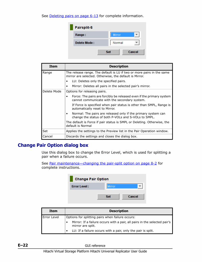
Hitachi Virtual Storage Platform Hitachi Universal Replicator User Guide
E–22 GUI reference
See Deleting pairs on page 6-13 for complete information.
Change Pair Option dialog boxUse this dialog box to change the Error Level, which is used for splitting a pair when a failure occurs.
See Pair maintenance—changing the pair-split option on page 8-2 for complete instructions.
Item Description
Range The release range. The default is LU if two or more pairs in the same mirror are selected. Otherwise, the default is Mirror.• LU: Deletes only the specified pairs. • Mirror: Deletes all pairs in the selected pair’s mirror.
Delete Mode Options for releasing pairs. • Force: The pairs are forcibly be released even if the primary system
cannot communicate with the secondary system. If Force is specified when pair status is other than SMPL, Range is automatically reset to Mirror.
• Normal: The pairs are released only if the primary system can change the status of both P-VOLs and S-VOLs to SMPL.
The default is Force if pair status is SMPL or Deleting. Otherwise, the default is Normal
Set Applies the settings to the Preview list in the Pair Operation window.
Cancel Discards the settings and closes the dialog box.
Item Description
Error Level Options for splitting pairs when failure occurs: • Mirror: If a failure occurs with a pair, all pairs in the selected pair’s
mirror are split.• LU: If a failure occurs with a pair, only the pair is split.
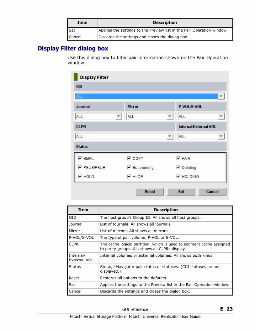
GUI reference E–23Hitachi Virtual Storage Platform Hitachi Universal Replicator User Guide
Display Filter dialog box Use this dialog box to filter pair information shown on the Pair Operation window.
Set Applies the settings to the Preview list in the Pair Operation window.
Cancel Discards the settings and closes the dialog box.
Item Description
Item Description
GID The host group’s Group ID. All shows all host groups.
Journal List of journals. All shows all journals.
Mirror List of mirrors. All shows all mirrors.
P-VOL/S-VOL The type of pair volume, P-VOL or S-VOL.
CLPR The cache logical partition, which is used to segment cache assigned to parity groups. All, shows all CLPRs display.
Internal/External VOL
Internal volumes or external volumes. All shows both kinds.
Status Storage Navigator pair status or statuses. (CCI statuses are not displayed.)
Reset Restores all options to the defaults.
Set Applies the settings to the Preview list in the Pair Operation window.
Cancel Discards the settings and closes the dialog box.

Hitachi Virtual Storage Platform Hitachi Universal Replicator User Guide
E–24 GUI reference
DKC Operation window Use this window to view details about the remote systems, logical paths between systems, and ports on the local system.
You can perform these procedures from the window:• Configuring local and remote systems for UR on page 5-3 • Configuring additional logical paths on page 5-7• View one of the following:
Remote systems information on page E-26 Logical Path Information on page E-27 Port Information for the local system on page E-27
Information on the DKC Operation window is updated when you do one of the following:• Click File > Refresh on the menu bar.• Click Apply• Select another tab and then reselect the DKC Operation tab.• Close the DKC Status window.• Select Modify mode when you are in View mode.
Note: DKC is an acronym for disk controller, which controls an entire system. UR windows use the term "DKC" to indicate a system.
LDKC is an acronym for logical disk controller, and it also may be called logical DKC. LDKC is a controller that controls a logical system that exists in VSP. In the UR window, the term “LDKC” indicates a logical system.
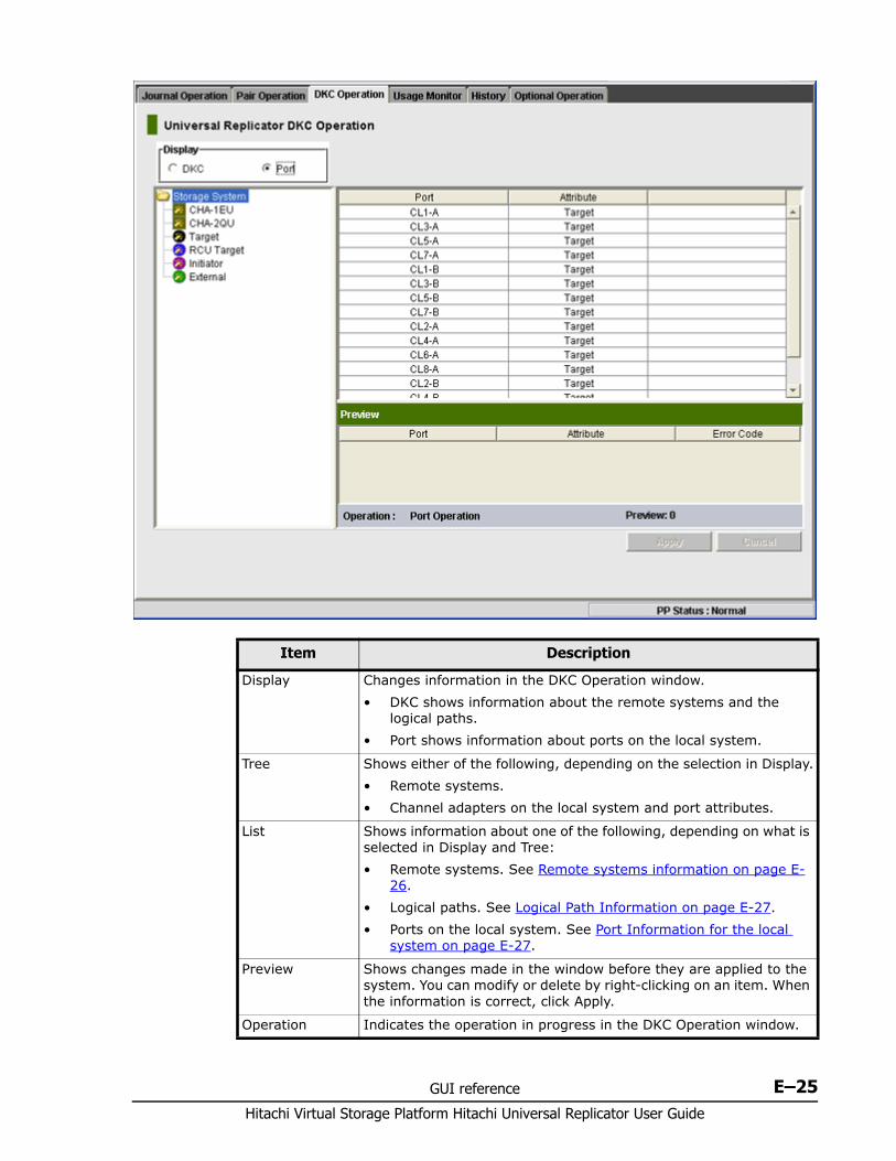
GUI reference E–25Hitachi Virtual Storage Platform Hitachi Universal Replicator User Guide
Item Description
Display Changes information in the DKC Operation window.• DKC shows information about the remote systems and the
logical paths.• Port shows information about ports on the local system.
Tree Shows either of the following, depending on the selection in Display.• Remote systems.• Channel adapters on the local system and port attributes.
List Shows information about one of the following, depending on what is selected in Display and Tree:• Remote systems. See Remote systems information on page E-
26.• Logical paths. See Logical Path Information on page E-27.• Ports on the local system. See Port Information for the local
system on page E-27.
Preview Shows changes made in the window before they are applied to the system. You can modify or delete by right-clicking on an item. When the information is correct, click Apply.
Operation Indicates the operation in progress in the DKC Operation window.
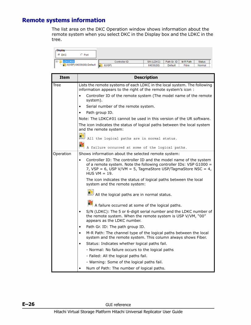
Hitachi Virtual Storage Platform Hitachi Universal Replicator User Guide
E–26 GUI reference
Remote systems information The list area on the DKC Operation window shows information about the remote system when you select DKC in the Display box and the LDKC in the tree.
Item Description
Tree Lists the remote systems of each LDKC in the local system. The following information appears to the right of the remote system’s icon :• Controller ID of the remote system (The model name of the remote
system).• Serial number of the remote system.• Path group ID.Note: The LDKC#01 cannot be used in this version of the UR software.The icon indicates the status of logical paths between the local system and the remote system:
All the logical paths are in normal status.
A failure occurred at some of the logical paths.
Operation Shows information about the selected remote system:• Controller ID: The controller ID and the model name of the system
of a remote system. Note the following controller IDs: VSP G1000 = 7, VSP = 6, USP V/VM = 5, TagmaStore USP/TagmaStore NSC = 4, HUS VM = 19. The icon indicates the status of logical paths between the local system and the remote system:
All the logical paths are in normal status.
A failure occurred at some of the logical paths.• S/N (LDKC): The 5 or 6-digit serial number and the LDKC number of
the remote system. When the remote system is USP V/VM, “00” appears as the LDKC number.
• Path Gr. ID: The path group ID. • M-R Path: The channel type of the logical paths between the local
system and the remote system. This column always shows Fiber.• Status: Indicates whether logical paths fail.
- Normal: No failure occurs to the logical paths- Failed: All the logical paths fail.- Warning: Some of the logical paths fail.
• Num of Path: The number of logical paths.
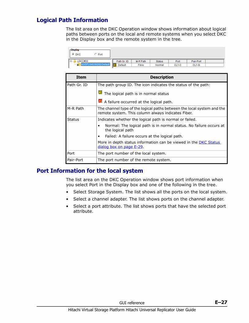
GUI reference E–27Hitachi Virtual Storage Platform Hitachi Universal Replicator User Guide
Logical Path InformationThe list area on the DKC Operation window shows information about logical paths between ports on the local and remote systems when you select DKC in the Display box and the remote system in the tree.
Port Information for the local systemThe list area on the DKC Operation window shows port information when you select Port in the Display box and one of the following in the tree.• Select Storage System. The list shows all the ports on the local system.• Select a channel adapter. The list shows ports on the channel adapter.• Select a port attribute. The list shows ports that have the selected port
attribute.
Item Description
Path Gr. ID The path group ID. The icon indicates the status of the path:
The logical path is in normal status
A failure occurred at the logical path.
M-R Path The channel type of the logical paths between the local system and the remote system. This column always indicates Fiber.
Status Indicates whether the logical path is normal or failed.• Normal: The logical path is in normal status. No failure occurs at
the logical path• Failed: A failure occurs at the logical path.More in depth status information can be viewed in the DKC Status dialog box on page E-29.
Port The port number of the local system.
Pair-Port The port number of the remote system.
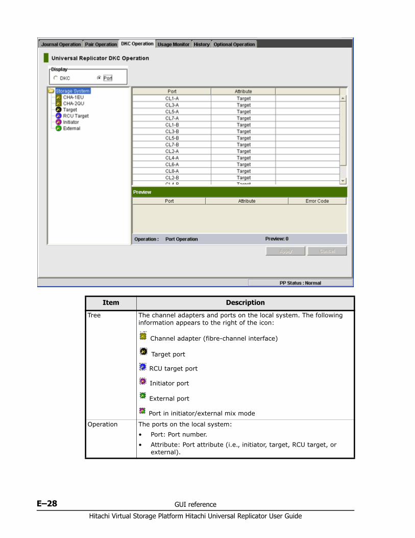
Hitachi Virtual Storage Platform Hitachi Universal Replicator User Guide
E–28 GUI reference
Item Description
Tree The channel adapters and ports on the local system. The following information appears to the right of the icon:
Channel adapter (fibre-channel interface)
Target port
RCU target port
Initiator port
External port
Port in initiator/external mix mode
Operation The ports on the local system:• Port: Port number.• Attribute: Port attribute (i.e., initiator, target, RCU target, or
external).
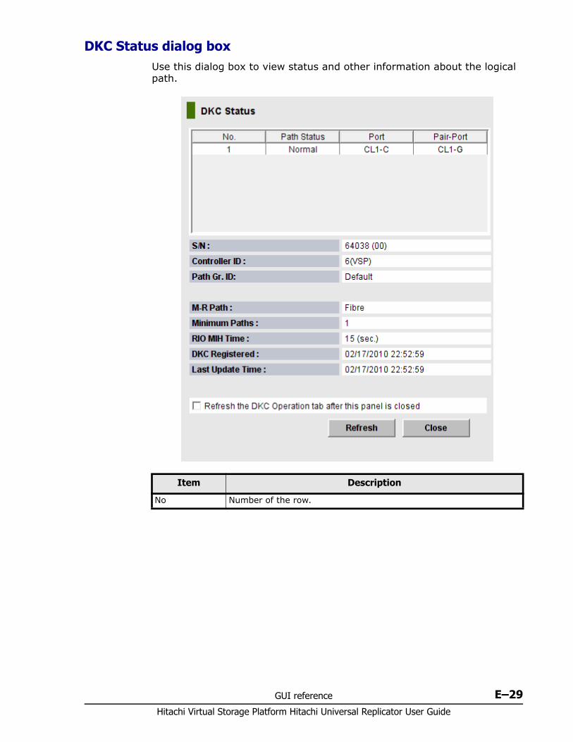
GUI reference E–29Hitachi Virtual Storage Platform Hitachi Universal Replicator User Guide
DKC Status dialog box Use this dialog box to view status and other information about the logical path.
Item Description
No Number of the row.
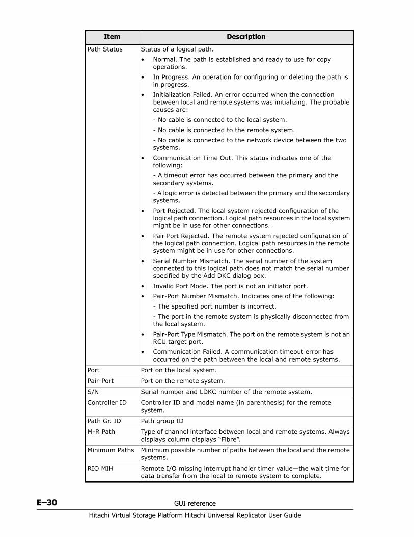
Hitachi Virtual Storage Platform Hitachi Universal Replicator User Guide
E–30 GUI reference
Path Status Status of a logical path. • Normal. The path is established and ready to use for copy
operations.• In Progress. An operation for configuring or deleting the path is
in progress.• Initialization Failed. An error occurred when the connection
between local and remote systems was initializing. The probable causes are:- No cable is connected to the local system.- No cable is connected to the remote system.- No cable is connected to the network device between the two systems.
• Communication Time Out. This status indicates one of the following:- A timeout error has occurred between the primary and the secondary systems.- A logic error is detected between the primary and the secondary systems.
• Port Rejected. The local system rejected configuration of the logical path connection. Logical path resources in the local system might be in use for other connections.
• Pair Port Rejected. The remote system rejected configuration of the logical path connection. Logical path resources in the remote system might be in use for other connections.
• Serial Number Mismatch. The serial number of the system connected to this logical path does not match the serial number specified by the Add DKC dialog box.
• Invalid Port Mode. The port is not an initiator port.• Pair-Port Number Mismatch. Indicates one of the following:
- The specified port number is incorrect.- The port in the remote system is physically disconnected from the local system.
• Pair-Port Type Mismatch. The port on the remote system is not an RCU target port.
• Communication Failed. A communication timeout error has occurred on the path between the local and remote systems.
Port Port on the local system.
Pair-Port Port on the remote system.
S/N Serial number and LDKC number of the remote system.
Controller ID Controller ID and model name (in parenthesis) for the remote system.
Path Gr. ID Path group ID
M-R Path Type of channel interface between local and remote systems. Always displays column displays “Fibre”.
Minimum Paths Minimum possible number of paths between the local and the remote systems.
RIO MIH Remote I/O missing interrupt handler timer value—the wait time for data transfer from the local to remote system to complete.
Item Description
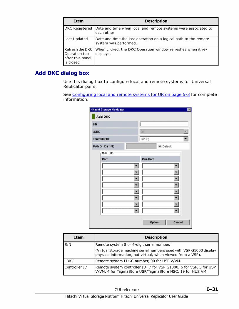
GUI reference E–31Hitachi Virtual Storage Platform Hitachi Universal Replicator User Guide
Add DKC dialog box Use this dialog box to configure local and remote systems for Universal Replicator pairs.
See Configuring local and remote systems for UR on page 5-3 for complete information.
DKC Registered Date and time when local and remote systems were associated to each other
Last Updated Date and time the last operation on a logical path to the remote system was performed.
Refresh the DKC Operation tab after this panel is closed
When clicked, the DKC Operation window refreshes when it re-displays.
Item Description
Item Description
S/N Remote system 5 or 6-digit serial number.(Virtual storage machine serial numbers used with VSP G1000 display physical information, not virtual, when viewed from a VSP).
LDKC Remote system LDKC number, 00 for USP V/VM.
Controller ID Remote system controller ID: 7 for VSP G1000, 6 for VSP, 5 for USP V/VM, 4 for TagmaStore USP/TagmaStore NSC, 19 for HUS VM.

Hitachi Virtual Storage Platform Hitachi Universal Replicator User Guide
E–32 GUI reference
DKC Option dialog box Use this dialog box to specify data transfer threshold time.
See Modifying data-transfer time threshold on page 8-10 for complete information.
Usage Monitor window Use this window to monitor remote copy operations data and I/O statistics.
See Monitoring copy operations data, I/O with Usage Monitor on page 7-11 for complete information.
Path Gr. ID ID for the path group, which is a group of multiple logical paths. For more information, see the Path group item in System requirements on page 2-2 .
M-R Path Logical path between local and remote systems.• Port: local system initiator port.• Pair-Port: remote system RCU target port.
Option Opens DKC Option dialog box.
Item Description
Item Description
Minimum Paths Minimum possible number of paths between the local and remote systems. The default is 1. In the current version, the number of minimum paths cannot be changed.
RIO MIH Time Amount of time the system waits before a data transfer operation is flagged as failed. The range is from 10-seconds to 100-seconds; 15-seconds is the default.
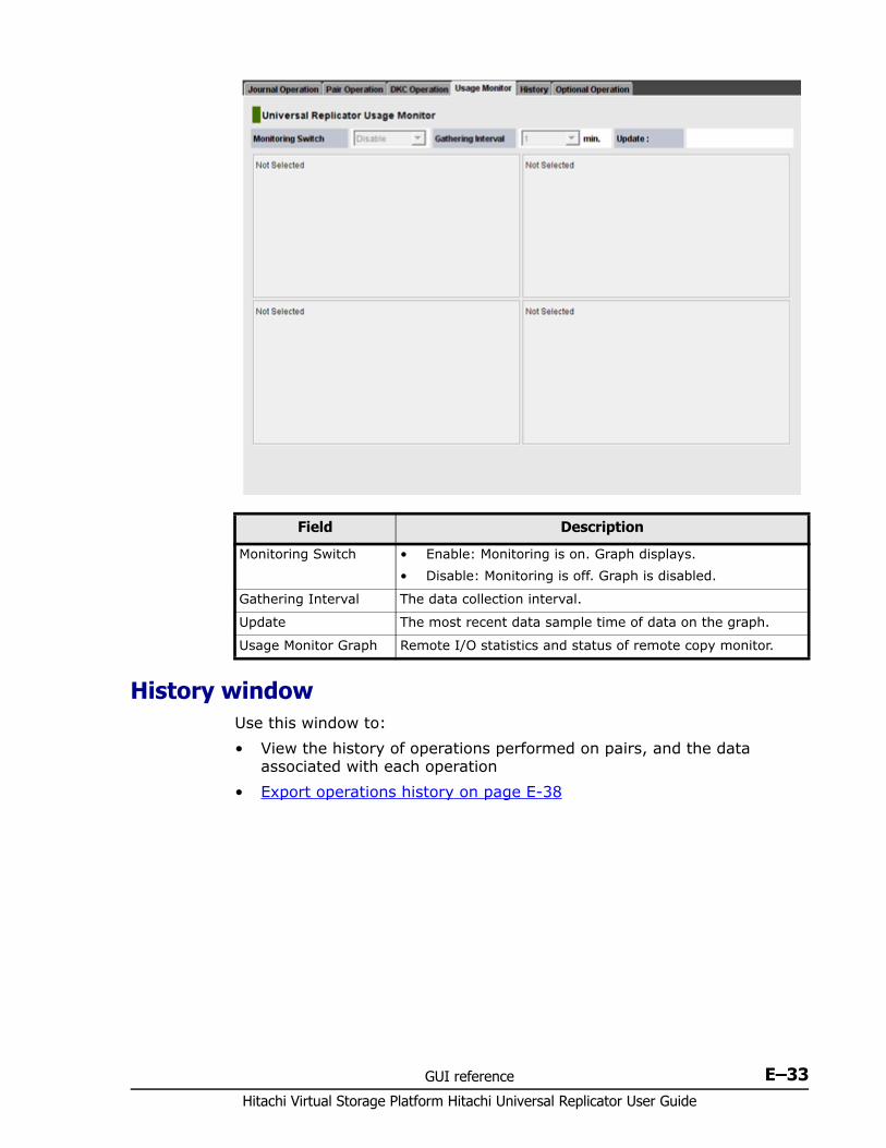
GUI reference E–33Hitachi Virtual Storage Platform Hitachi Universal Replicator User Guide
History window Use this window to:• View the history of operations performed on pairs, and the data
associated with each operation• Export operations history on page E-38
Field Description
Monitoring Switch • Enable: Monitoring is on. Graph displays.• Disable: Monitoring is off. Graph is disabled.
Gathering Interval The data collection interval.
Update The most recent data sample time of data on the graph.
Usage Monitor Graph Remote I/O statistics and status of remote copy monitor.

Hitachi Virtual Storage Platform Hitachi Universal Replicator User Guide
E–34 GUI reference
Item Description
Status The current status of operation history:• No history file exists: Operation history does not exist.• Reading a history file failed: An attempt to read operation history
failed.• Updating ... n (%): Updating of operation history is now in
progress, where "n (%)" indicates the progress (in %). When the updating is in progress, the checking process automatically continues until updating finishes. The updating process is checked at 10-second intervals.
• Complete: Updating of operation history has completed.
Last Update Time
The date and time when operation history was last updated.
Page The number of the current page and the total number of pages. The display format of Page is "the number of current page / total number of pages". If there is no history file, nothing appears.
Export Saves operation history in a CSV file. You cannot save the history file while operation history is being updated. Save operation history in a text file after operation history is updated. For more information, see Export operations history on page E-38.
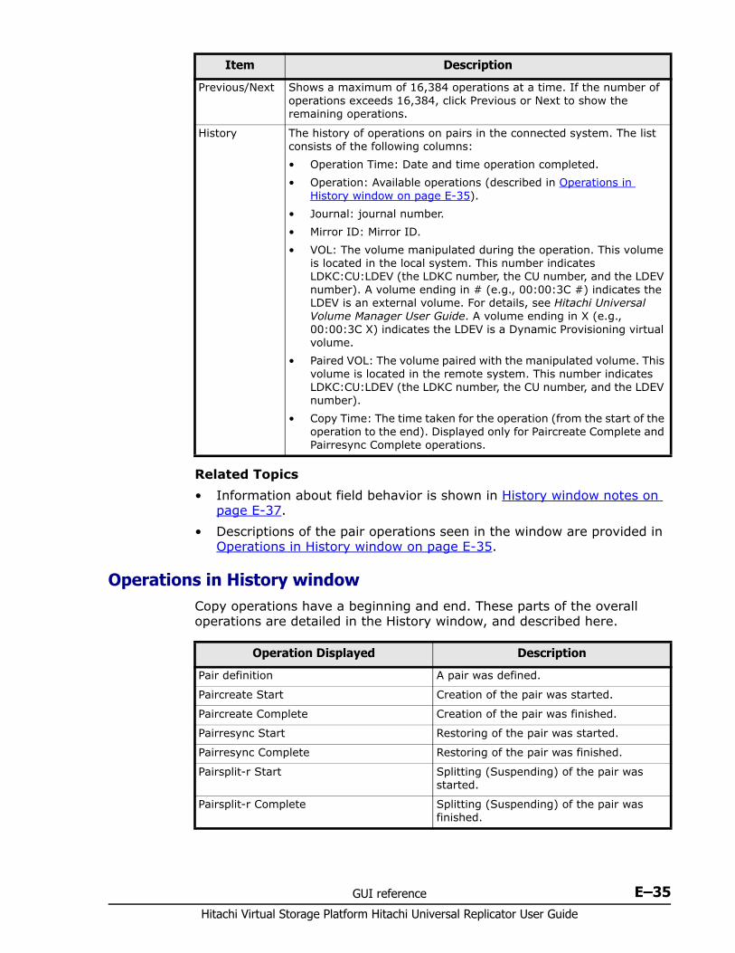
GUI reference E–35Hitachi Virtual Storage Platform Hitachi Universal Replicator User Guide
Related Topics• Information about field behavior is shown in History window notes on
page E-37.• Descriptions of the pair operations seen in the window are provided in
Operations in History window on page E-35.
Operations in History window Copy operations have a beginning and end. These parts of the overall operations are detailed in the History window, and described here.
Previous/Next Shows a maximum of 16,384 operations at a time. If the number of operations exceeds 16,384, click Previous or Next to show the remaining operations.
History The history of operations on pairs in the connected system. The list consists of the following columns:• Operation Time: Date and time operation completed.• Operation: Available operations (described in Operations in
History window on page E-35).• Journal: journal number.• Mirror ID: Mirror ID.• VOL: The volume manipulated during the operation. This volume
is located in the local system. This number indicates LDKC:CU:LDEV (the LDKC number, the CU number, and the LDEV number). A volume ending in # (e.g., 00:00:3C #) indicates the LDEV is an external volume. For details, see Hitachi Universal Volume Manager User Guide. A volume ending in X (e.g., 00:00:3C X) indicates the LDEV is a Dynamic Provisioning virtual volume.
• Paired VOL: The volume paired with the manipulated volume. This volume is located in the remote system. This number indicates LDKC:CU:LDEV (the LDKC number, the CU number, and the LDEV number).
• Copy Time: The time taken for the operation (from the start of the operation to the end). Displayed only for Paircreate Complete and Pairresync Complete operations.
Item Description
Operation Displayed Description
Pair definition A pair was defined.
Paircreate Start Creation of the pair was started.
Paircreate Complete Creation of the pair was finished.
Pairresync Start Restoring of the pair was started.
Pairresync Complete Restoring of the pair was finished.
Pairsplit-r Start Splitting (Suspending) of the pair was started.
Pairsplit-r Complete Splitting (Suspending) of the pair was finished.
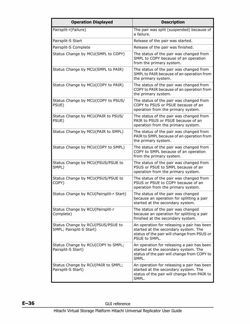
Hitachi Virtual Storage Platform Hitachi Universal Replicator User Guide
E–36 GUI reference
Pairsplit-r(Failure) The pair was split (suspended) because of a failure.
Pairsplit-S Start Release of the pair was started.
Pairsplit-S Complete Release of the pair was finished.
Status Change by MCU(SMPL to COPY) The status of the pair was changed from SMPL to COPY because of an operation from the primary system.
Status Change by MCU(SMPL to PAIR) The status of the pair was changed from SMPL to PAIR because of an operation from the primary system.
Status Change by MCU(COPY to PAIR) The status of the pair was changed from COPY to PAIR because of an operation from the primary system.
Status Change by MCU(COPY to PSUS/PSUE)
The status of the pair was changed from COPY to PSUS or PSUE because of an operation from the primary system.
Status Change by MCU(PAIR to PSUS/PSUE)
The status of the pair was changed from PAIR to PSUS or PSUE because of an operation from the primary system.
Status Change by MCU(PAIR to SMPL) The status of the pair was changed from PAIR to SMPL because of an operation from the primary system.
Status Change by MCU(COPY to SMPL) The status of the pair was changed from COPY to SMPL because of an operation from the primary system.
Status Change by MCU(PSUS/PSUE to SMPL)
The status of the pair was changed from PSUS or PSUE to SMPL because of an operation from the primary system.
Status Change by MCU(PSUS/PSUE to COPY)
The status of the pair was changed from PSUS or PSUE to COPY because of an operation from the primary system.
Status Change by RCU(Pairsplit-r Start) The status of the pair was changed because an operation for splitting a pair started at the secondary system.
Status Change by RCU(Pairsplit-r Complete)
The status of the pair was changed because an operation for splitting a pair finished at the secondary system.
Status Change by RCU(PSUS/PSUE to SMPL; Pairsplit-S Start)
An operation for releasing a pair has been started at the secondary system. The status of the pair will change from PSUS or PSUE to SMPL.
Status Change by RCU(COPY to SMPL; Pairsplit-S Start)
An operation for releasing a pair has been started at the secondary system. The status of the pair will change from COPY to SMPL.
Status Change by RCU(PAIR to SMPL; Pairsplit-S Start)
An operation for releasing a pair has been started at the secondary system. The status of the pair will change from PAIR to SMPL.
Operation Displayed Description
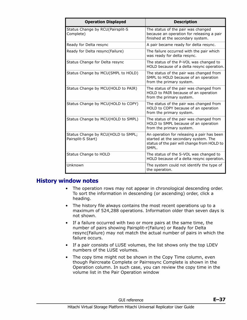
GUI reference E–37Hitachi Virtual Storage Platform Hitachi Universal Replicator User Guide
History window notes• The operation rows may not appear in chronological descending order.
To sort the information in descending (or ascending) order, click a heading.
• The history file always contains the most recent operations up to a maximum of 524,288 operations. Information older than seven days is not shown.
• If a failure occurred with two or more pairs at the same time, the number of pairs showing Pairsplit-r(Failure) or Ready for Delta resync(Failure) may not match the actual number of pairs in which the failure occurs.
• If a pair consists of LUSE volumes, the list shows only the top LDEV numbers of the LUSE volumes.
• The copy time might not be shown in the Copy Time column, even though Paircreate Complete or Pairresync Complete is shown in the Operation column. In such case, you can review the copy time in the volume list in the Pair Operation window
Status Change by RCU(Pairsplit-S Complete)
The status of the pair was changed because an operation for releasing a pair finished at the secondary system.
Ready for Delta resync A pair became ready for delta resync.
Ready for Delta resync(Failure) The failure occurred with the pair which was ready for delta resync.
Status Change for Delta resync The status of the P-VOL was changed to HOLD because of a delta resync operation.
Status Change by MCU(SMPL to HOLD) The status of the pair was changed from SMPL to HOLD because of an operation from the primary system.
Status Change by MCU(HOLD to PAIR) The status of the pair was changed from HOLD to PAIR because of an operation from the primary system.
Status Change by MCU(HOLD to COPY) The status of the pair was changed from HOLD to COPY because of an operation from the primary system.
Status Change by MCU(HOLD to SMPL) The status of the pair was changed from HOLD to SMPL because of an operation from the primary system.
Status Change by RCU(HOLD to SMPL; Pairsplit-S Start)
An operation for releasing a pair has been started at the secondary system. The status of the pair will change from HOLD to SMPL.
Status Change to HOLD The status of the S-VOL was changed to HOLD because of a delta resync operation.
Unknown The system could not identify the type of the operation.
Operation Displayed Description
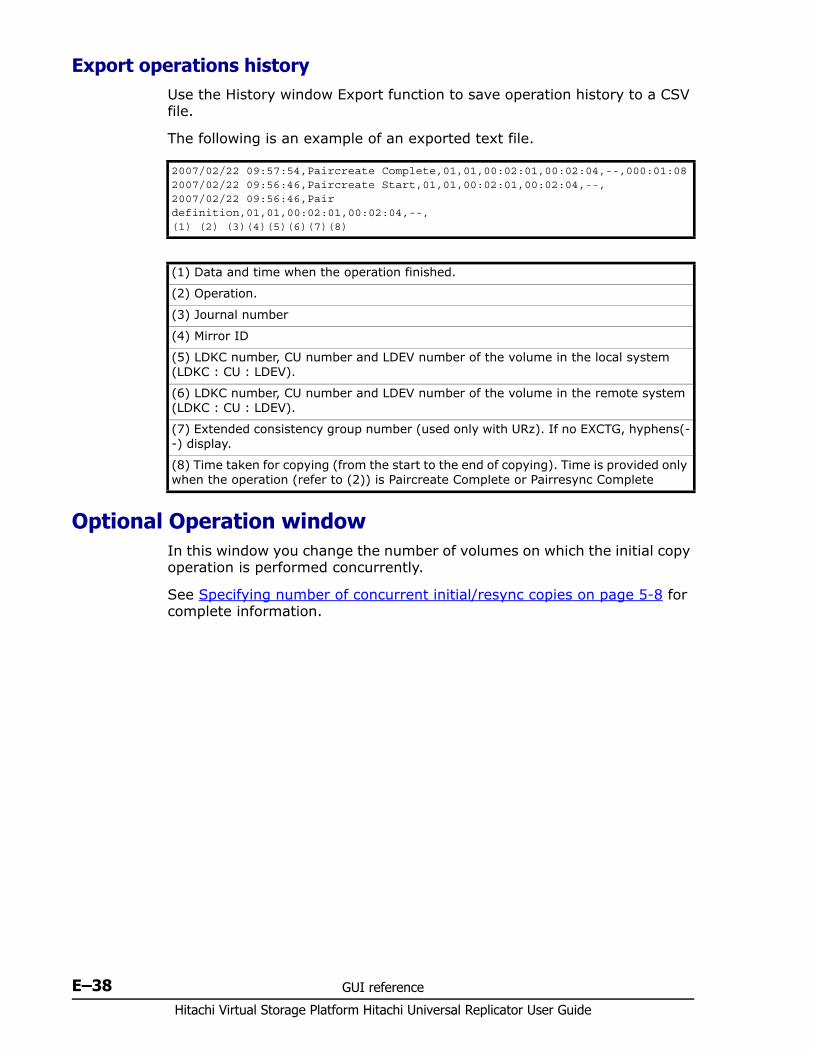
Hitachi Virtual Storage Platform Hitachi Universal Replicator User Guide
E–38 GUI reference
Export operations history Use the History window Export function to save operation history to a CSV file.
The following is an example of an exported text file.
Optional Operation window In this window you change the number of volumes on which the initial copy operation is performed concurrently.
See Specifying number of concurrent initial/resync copies on page 5-8 for complete information.
2007/02/22 09:57:54,Paircreate Complete,01,01,00:02:01,00:02:04,--,000:01:082007/02/22 09:56:46,Paircreate Start,01,01,00:02:01,00:02:04,--, 2007/02/22 09:56:46,Pair definition,01,01,00:02:01,00:02:04,--, (1) (2) (3)(4)(5)(6)(7)(8)
(1) Data and time when the operation finished.
(2) Operation.
(3) Journal number
(4) Mirror ID
(5) LDKC number, CU number and LDEV number of the volume in the local system (LDKC : CU : LDEV).
(6) LDKC number, CU number and LDEV number of the volume in the remote system (LDKC : CU : LDEV).
(7) Extended consistency group number (used only with URz). If no EXCTG, hyphens(--) display.
(8) Time taken for copying (from the start to the end of copying). Time is provided only when the operation (refer to (2)) is Paircreate Complete or Pairresync Complete
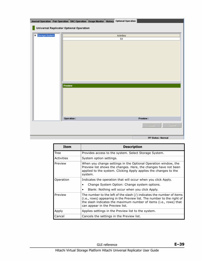
GUI reference E–39Hitachi Virtual Storage Platform Hitachi Universal Replicator User Guide
Item Description
Tree Provides access to the system. Select Storage System.
Activities System option settings.
Preview When you change settings in the Optional Operation window, the Preview list shows the changes. Here, the changes have not been applied to the system. Clicking Apply applies the changes to the system.
Operation Indicates the operation that will occur when you click Apply.• Change System Option: Change system options.• Blank: Nothing will occur when you click Apply.
Preview The number to the left of the slash (/) indicates the number of items (i.e., rows) appearing in the Preview list. The number to the right of the slash indicates the maximum number of items (i.e., rows) that can appear in the Preview list.
Apply Applies settings in the Preview list to the system.
Cancel Cancels the settings in the Preview list.

Hitachi Virtual Storage Platform Hitachi Universal Replicator User Guide
E–40 GUI reference
CA KD E F G H I J L M N O P Q R S T U V W X Y# B Z# A B C D E F G H I J L M N O P Q R S T U V
Glossary–1Hitachi Virtual Storage Platform Hitachi Universal Replicator User Guide
Glossary
This glossary defines the special terms used in this document. Click the letter links below to navigate.
#
2DCtwo-data-center. Refers to the local and remote sites, or data centers, in which TrueCopy (TC) and Universal Replicator (UR) combine to form a remote replication configuration.
In a 2DC configuration, data is copied from a TC primary volume at the local site to the UR master journal volume at an intermediate site, then replicated to the UR secondary volume at the remote site. Since this configuration side-steps the TC secondary volume at the intermediate site, the intermediate site is not considered a data center.
3DCthree-data-center. Refers to the local, intermediate, and remote sites, or data centers, in which TrueCopy and Universal Replicator combine to form a remote replication configuration.
In a 3DC configuration, data is copied from a local site to an intermediate site and then to a remote site (3DC cascade configuration), or from a local site to two separate remote sites (3DC multi-target configuration).
A
alternate pathA secondary path (port, target ID, LUN) to a logical volume, in addition to the primary path, that is used as a backup in case the primary path fails.
CA KD E F G H I J L M N O P Q R S T U V W X Y# B Z# A B C D E F G H I J L M N O P Q R S T U V
Hitachi Virtual Storage Platform Hitachi Universal Replicator User Guide
Glossary–2
arrayAnother name for a RAID storage system.
array groupSee RAID group.
asyncasynchronous
at-time splitConsistency group operation that performs multiple pairsplit operations at a pre-determined time.
audit logFiles that store a history of the operations performed from SN and the service processor (SVP), commands that the storage system received from hosts, and data encryption operations.
B
base emulation typeEmulation type that is set when drives are installed. Determines the device emulation types that can be set in the RAID group.
BCbusiness continuity
BCMBusiness Continuity Manager
bladeA computer module, generally a single circuit board, used mostly in servers.
BLK, blkblock
bmpbitmap
C
C/TSee consistency time (C/T).
CA KD E F G H I J L M N O P Q R S T U V W X Y# B Z# A B C D E F G H I J L M N O P Q R S T U V
Glossary–3Hitachi Virtual Storage Platform Hitachi Universal Replicator User Guide
cacache
cache logical partition (CLPR)Consists of virtual cache memory that is set up to be allocated to different hosts in contention for cache memory.
capacityThe amount of data storage space available on a physical storage device, usually measured in bytes (MB, GB, TB, etc.).
cascade configurationIn a 3DC cascade configuration for remote replication, data is copied from a local site to an intermediate site and then to a remote site using TrueCopy and Universal Replicator. See also 3DC.
In a ShadowImage cascade configuration, two layers of secondary volumes can be defined for a single primary volume. Pairs created in the first and second layer are called cascaded pairs.
cascade functionA ShadowImage function for open systems where a primary volume (P-VOL) can have up to nine secondary volumes (S-VOLs) in a layered configuration. The first cascade layer (L1) is the original ShadowImage pair with one P-VOL and up to three S-VOLs. The second cascade layer (L2) contains ShadowImage pairs in which the L1 S-VOLs are functioning as the P-VOLs of layer-2 ShadowImage pairs that can have up to two S-VOLs for each P-VOL.
See also root volume, node volume, leaf volume, level-1 pair, and level-2 pair.
cascaded pairA ShadowImage pair in a cascade configuration. See cascade configuration.
shared volumeA volume that is being used by more than one replication function. For example, a volume that is the primary volume of a TrueCopy pair and the primary volume of a ShadowImage pair is a shared volume.
CCICommand Control Interface
CFLConfiguration File Loader. A SN function for validating and running scripted spreadsheets.
CA KD E F G H I J L M N O P Q R S T U V W X Y# B Z# A B C D E F G H I J L M N O P Q R S T U V
Hitachi Virtual Storage Platform Hitachi Universal Replicator User Guide
Glossary–4
CFWcache fast write
CGSee consistency group (CTG).
CTGSee consistency group (CTG).
CHchannel
channel pathThe communication path between a channel and a control unit. A channel path consists of the physical channel path and the logical path.
CHAPchallenge handshake authentication protocol
CLcluster
CLIcommand line interface
CLPRcache logical partition
clusterMultiple-storage servers working together to respond to multiple read and write requests.
command deviceA dedicated logical volume used only by Command Control Interface and Business Continuity Manager to interface with the storage system. Can be shared by several hosts.
configuration definition fileDefines the configuration, parameters, and options of Command Control Interface operations. A text file that defines the connected hosts and the volumes and groups known to the Command Control Interface instance.
CA KD E F G H I J L M N O P Q R S T U V W X Y# B Z# A B C D E F G H I J L M N O P Q R S T U V
Glossary–5Hitachi Virtual Storage Platform Hitachi Universal Replicator User Guide
consistency group (CG, CTG)A group of pairs on which copy operations are performed simultaneously; the pairs’ status changes at the same time. See also extended consistency group (EXCTG).
consistency time (C/T)Shows a time stamp to indicate how close the target volume is to the source volume. C/T also shows the time stamp of a journal and extended consistency group.
controllerThe component in a storage system that manages all storage functions. It is analogous to a computer and contains a processors, I/O devices, RAM, power supplies, cooling fans, and other sub-components as needed to support the operation of the storage system.
copy-on-writePoint-in-time snapshot copy of any data volume within a storage system. Snapshots store only changed data blocks, therefore the amount of storage capacity required for each copy is substantially smaller than the source volume.
copy pairA pair of volumes in which one volume contains original data and the other volume contains the copy of the original. Copy operations can be synchronous or asynchronous, and the volumes of the copy pair can be located in the same storage system (local copy) or in different storage systems (remote copy).
A copy pair can also be called a volume pair, or just pair.
COWcopy-on-write
COW SnapshotHitachi Copy-on-Write Snapshot
CTGSee consistency group (CTG).
CTLcontroller
CUcontrol unit
CA KD E F G H I J L M N O P Q R S T U V W X Y# B Z# A B C D E F G H I J L M N O P Q R S T U V
Hitachi Virtual Storage Platform Hitachi Universal Replicator User Guide
Glossary–6
currency of dataThe synchronization of the volumes in a copy pair. When the data on the secondary volume (S-VOL) is identical to the data on the primary volume (P-VOL), the data on the S-VOL is current. When the data on the S-VOL is not identical to the data on the P-VOL, the data on the S-VOL is not current.
CYL, cylcylinder
cylinder bitmapIndicates the differential data (updated by write I/Os) in a volume of a split or suspended copy pair. The primary and secondary volumes each have their own cylinder bitmap. When the pair is resynchronized, the cylinder bitmaps are merged, and the differential data is copied to the secondary volume.
D
DASDdirect-access storage device
data consistencyWhen the data on the secondary volume is identical to the data on the primary volume.
data pathThe physical paths used by primary storage systems to communicate with secondary storage systems in a remote replication environment.
data poolOne or more logical volumes designated to temporarily store original data. When a snapshot is taken of a primary volume, the data pool is used if a data block in the primary volume is to be updated. The original snapshot of the volume is maintained by storing the to-be-changed data blocks in the data pool.
DBdatabase
DBMSdatabase management system
CA KD E F G H I J L M N O P Q R S T U V W X Y# B Z# A B C D E F G H I J L M N O P Q R S T U V
Glossary–7Hitachi Virtual Storage Platform Hitachi Universal Replicator User Guide
delta resyncA disaster recovery solution in which TrueCopy and Universal Replicator systems are configured to provide a quick recovery using only differential data stored at an intermediate site.
deviceA physical or logical unit with a specific function.
device emulationIndicates the type of logical volume. Mainframe device emulation types provide logical volumes of fixed size, called logical volume images (LVIs), which contain EBCDIC data in CKD format. Typical mainframe device emulation types include 3390-9 and 3390-M. Open-systems device emulation types provide logical volumes of variable size, called logical units (LUs), that contain ASCII data in FBA format. The typical open-systems device emulation type is OPEN-V.
DEVNdevice number
DFWDASD fast write
DHCPdynamic host configuration protocol
differential dataChanged data in the primary volume not yet reflected in the copy.
disaster recoveryA set of procedures to recover critical application data and processing after a disaster or other failure.
disk arrayDisk array, or just array, is another name for a RAID storage system.
disk controller (DKC)The hardware component that manages front-end and back-end storage operations. The term DKC is sometimes used to refer to the entire RAID storage system.
DKCdisk controller. Can refer to the RAID storage system or the controller components.
CA KD E F G H I J L M N O P Q R S T U V W X Y# B Z# A B C D E F G H I J L M N O P Q R S T U V
Hitachi Virtual Storage Platform Hitachi Universal Replicator User Guide
Glossary–8
DKCMAINdisk controller main. Refers to the microcode for the RAID storage system.
DKPdisk processor. Refers to the microprocessors on the back-end director features of the Universal Storage Platform V.
DKUdisk unit. Refers to the cabinet (floor model) or rack-mounted hardware component that contains data drives and no controller components.
DMPDynamic Multi Pathing
DRUHitachi Data Retention Utility
DP-VOLDynamic Provisioning-virtual volume. A virtual volume with no memory space used by Dynamic Provisioning.
dynamic provisioningAn approach to managing storage. Instead of “reserving” a fixed amount of storage, it removes capacity from the available pool when data is actually written to disk. Also called thin provisioning.
E
ECerror code
emulationThe operation of the Hitachi RAID storage system to emulate the characteristics of a different storage system. For device emulation the mainframe host “sees” the logical devices on the RAID storage system as 3390-x devices. For controller emulation the mainframe host “sees” the control units (CUs) on the RAID storage system as 2105 or 2107 controllers.
RAID storage system operates the same as the storage system being emulated.
emulation groupA set of device emulation types that can be intermixed within a RAID group and treated as a group.
CA KD E F G H I J L M N O P Q R S T U V W X Y# B Z# A B C D E F G H I J L M N O P Q R S T U V
Glossary–9Hitachi Virtual Storage Platform Hitachi Universal Replicator User Guide
env.environment
ERCerror reporting communications
ESCONEnterprise System Connection
EXCTGSee extended consistency group (ECTG).
EXGexternal volume group
ext.external
extended consistency group (EXCTG)A set of Universal Replicator for Mainframe journals in which data consistency is guaranteed. When performing copy operations between multiple primary and secondary storage systems, the journals must be registered in an EXCTG.
external applicationA software module that is used by a storage system but runs on a separate platform.
external portA fibre-channel port that is configured to be connected to an external storage system for Universal Volume Manager operations.
external volumeA logical volume whose data resides on drives that are physically located outside the Hitachi storage system.
F
failbackThe process of switching operations from the secondary path or host back to the primary path or host, after the primary path or host has recovered from failure. See also failover.
CA KD E F G H I J L M N O P Q R S T U V W X Y# B Z# A B C D E F G H I J L M N O P Q R S T U V
Hitachi Virtual Storage Platform Hitachi Universal Replicator User Guide
Glossary–10
failoverThe process of switching operations from the primary path or host to a secondary path or host when the primary path or host fails.
FBAfixed-block architecture
FCfibre channel; FlashCopy
FCAfibre-channel adapter
FC-ALfibre-channel arbitrated loop
FCIPfibre-channel internet protocol
FCPfibre-channel protocol
FCSPfibre-channel security protocol
FIBARCFibre Connection Architecture
FICONFibre Connectivity
FIFOfirst in, first out
free capacityThe amount of storage space (in bytes) that is available for use by the host systems.
FSWfibre switch
FTPfile-transfer protocol
CA KD E F G H I J L M N O P Q R S T U V W X Y# B Z# A B C D E F G H I J L M N O P Q R S T U V
Glossary–11Hitachi Virtual Storage Platform Hitachi Universal Replicator User Guide
FVfixed-size volume
FWDfast-wide differential
G
GIDgroup ID
GUIgraphical user interface
H
HAhigh availability
HACMPHigh Availability Cluster Multi-Processing
HAMHitachi High Availability Manager
HDLMHitachi Dynamic Link Manager
HDPHitachi Dynamic Provisioning
HDSHitachi Data Systems
HDTHitachi Dynamic Tiering
HDvMHitachi Device Manager
HGLAMHitachi Global Link Availability Manager
CA KD E F G H I J L M N O P Q R S T U V W X Y# B Z# A B C D E F G H I J L M N O P Q R S T U V
Hitachi Virtual Storage Platform Hitachi Universal Replicator User Guide
Glossary–12
H-LUNhost logical unit
HOMRCFHitachi Open Multi-RAID Coupling Feature. Another name for Hitachi ShadowImage.
HORCHitachi Open Remote Copy. Another name for Hitachi TrueCopy.
HORCMHitachi Open Remote Copy Manager. Another name for Command Control Interface.
host failoverThe process of switching operations from one host to another host when the primary host fails.
host groupA group of hosts of the same operating system platform.
host modeOperational modes that provide enhanced compatibility with supported host platforms. Used with fibre-channel ports on RAID storage systems.
host mode optionAdditional options for fibre-channel ports on RAID storage systems. Provide enhanced functionality for host software and middleware.
HRCHitachi Remote Copy. Another name for Hitachi TrueCopy for IBM z/OS.
HRpMHitachi Replication Manager
HSCSHitachi Storage Command Suite. This suite of products is now called the Hitachi Command Suite.
HURHitachi Universal Replicator
CA KD E F G H I J L M N O P Q R S T U V W X Y# B Z# A B C D E F G H I J L M N O P Q R S T U V
Glossary–13Hitachi Virtual Storage Platform Hitachi Universal Replicator User Guide
HXRCHitachi Extended Remote Copy. Another name for Hitachi Compatible Replication for IBM XRC.
I
iFCPinternet fibre-channel protocol
IMLinitial microcode load; initial microprogram load
IMPLinitial microprogram load
initial copyAn initial copy operation is performed when a copy pair is created. Data on the primary volume is copied to the secondary volume.
initiator portA fibre-channel port configured to send remote I/Os to an RCU target port on another storage system. See also RCU target port and target port.
in-system replicationThe original data volume and its copy are located in the same storage system. ShadowImage in-system replication provides duplication of logical volumes; Copy-on-Write Snapshot in-system replication provides “snapshots” of logical volumes that are stored and managed as virtual volumes (V-VOLs).
See also remote replication.
intermediate site (I-site)A site that functions as both a TrueCopy secondary site and a Universal Replicator primary site in a 3-data-center (3DC) cascading configuration.
internal volumeA logical volume whose data resides on drives that are physically located within the storage system. See also external volume.
IO, I/Oinput/output
CA KD E F G H I J L M N O P Q R S T U V W X Y# B Z# A B C D E F G H I J L M N O P Q R S T U V
Hitachi Virtual Storage Platform Hitachi Universal Replicator User Guide
Glossary–14
IOPSI/Os per second
IPinternet protocol
IPLinitial program load
J
JNLjournal
JNLGjournal group
journal group (JNLG)In a Universal Replicator system, journal groups manage data consistency between multiple primary volumes and secondary volumes. See also consistency group (CTG).
journal volumeA volume that records and stores a log of all events that take place in another volume. In the event of a system crash, the journal volume logs are used to restore lost data and maintain data integrity.
In Universal Replicator, differential data is held in journal volumes on until it is copied to the S-VOL.
JREJava Runtime Environment
L
L1 pairSee layer-1 (L1) pair.
L2 pairSee layer-2 (L2) pair.
LANlocal-area network

CA KD E F G H I J L M N O P Q R S T U V W X Y# B Z# A B C D E F G H I J L M N O P Q R S T U V
Glossary–15Hitachi Virtual Storage Platform Hitachi Universal Replicator User Guide
layer-1 (L1) pairIn a ShadowImage cascade configuration, a layer-1 pair consists of a primary volume and secondary volume in the first cascade layer. An L1 primary volume can be paired with up to three L1 secondary volumes. See also cascade configuration.
layer-2 (L2) pairIn a ShadowImage cascade configuration, a layer-2 (L2) pair consists of a primary volume and secondary volume in the second cascade layer. An L2 primary volume can be paired with up to two L2 secondary volumes. See also cascade configuration.
LBAlogical block address
LCPlocal control port; link control processor
LCUlogical control unit
LDEVlogical device
LDKCSee logical disk controller (LDKC).
leaf volumeA level-2 secondary volume in a ShadowImage cascade configuration. The primary volume of a layer-2 pair is called a node volume. See also cascade configuration.
LEDlight-emitting diode
license keyA specific set of characters that unlocks a software application so that you can use it.
local copySee in-system replication.
local siteSee primary site.
CA KD E F G H I J L M N O P Q R S T U V W X Y# B Z# A B C D E F G H I J L M N O P Q R S T U V
Hitachi Virtual Storage Platform Hitachi Universal Replicator User Guide
Glossary–16
logical device (LDEV)An individual logical data volume (on multiple drives in a RAID configuration) in the storage system. An LDEV may or may not contain any data and may or may not be defined to any hosts. Each LDEV has a unique identifier or “address” within the storage system composed of the logical disk controller (LDKC) number, control unit (CU) number, and LDEV number. The LDEV IDs within a storage system do not change.An LDEV formatted for use by mainframe hosts is called a logical volume image (LVI). An LDEV formatted for use by open-system hosts is called a logical unit (LU).
logical disk controller (LDKC)A group of 255 control unit (CU) images in the RAID storage system that is controlled by a virtual (logical) storage system within the single physical storage system. For example, the Universal Storage Platform V storage system supports two LDKCs, LDKC 00 and LDKC 01.
logical unit (LU)A logical volume that is configured for use by open-systems hosts (for example, OPEN-V).
logical unit (LU) pathThe path between an open-systems host and a logical unit.
logical volumeSee volume.
logical volume image (LVI)A logical volume that is configured for use by mainframe hosts (for example, 3390-9).
LUlogical unit
LUNlogical unit number
LUNMHitachi LUN Manager
LUSEHitachi LUN Expansion; Hitachi LU Size Expansion
LVlogical volume
CA KD E F G H I J L M N O P Q R S T U V W X Y# B Z# A B C D E F G H I J L M N O P Q R S T U V
Glossary–17Hitachi Virtual Storage Platform Hitachi Universal Replicator User Guide
M
main control unit (MCU)A storage system at a primary or main site that contains primary volumes of TrueCopy for Mainframe remote replication pairs. The MCU is configured to send remote I/Os to one or more storage systems at the secondary or remote site, called remote control units (RCUs), that contain the secondary volumes of the remote replication pairs. See also remote control unit (RCU).
main siteSee primary site.
main volume (M-VOL)A primary volume on the main storage system in a TrueCopy for Mainframe copy pair. The M-VOL contains the original data that is duplicated on the remote volume (R-VOL). See also remote volume (R-VOL).
master journal (M-JNL)Holds differential data on the primary Universal Replicator system until it is copied to the restore journal (R-JNL) on the secondary storage system. See also restore journal (R-JNL).
max.maximum
MBmegabyte
Mb/sec, Mbpsmegabits per second
MB/sec, MBpsmegabytes per second
MCUSee main control unit (MCU).
MF, M/Fmainframe
MIHmissing interrupt handler
CA KD E F G H I J L M N O P Q R S T U V W X Y# B Z# A B C D E F G H I J L M N O P Q R S T U V
Hitachi Virtual Storage Platform Hitachi Universal Replicator User Guide
Glossary–18
mirrorIn Universal Replicator, each pair relationship in and between journals is called a “mirror”. Each pair is assigned a mirror ID when it is created. The mirror ID identifies individual pair relationships between journals.
M-JNLmain journal
modify modeThe mode of operation of SN where you can change the the storage system configuration.
MPmicroprocessor
MSCSMicrosoft Cluster Server
mto, MTOmainframe-to-open
MUmirror unit
multi-pathingA performance and fault-tolerant technique that uses more than one physical connection between the storage system and host system. Also called multipath I/O.
M-VOLmain volume
N
node volumeA level-2 primary volume in a ShadowImage cascade configuration. The secondary volume of a layer-2 pair is called a leaf volume. See also cascade configuration.
NUMnumber
NVSnonvolatile storage
CA KD E F G H I J L M N O P Q R S T U V W X Y# B Z# A B C D E F G H I J L M N O P Q R S T U V
Glossary–19Hitachi Virtual Storage Platform Hitachi Universal Replicator User Guide
O
OPEN-VA logical unit (LU) of user-defined size that is formatted for use by open-systems hosts.
OPEN-xA logical unit (LU) of fixed size (for example, OPEN-3 or OPEN-9) that is used primarily for sharing data between mainframe and open-systems hosts using Hitachi Cross-OS File Exchange.
OSoperating system
OS/390Operating System/390
P
pairTwo logical volumes in a replication relationship in which one volume contains original data to be copied and the other volume contains the copy of the original data. The copy operations can be synchronous or asynchronous, and the pair volumes can be located in the same storage system (in-system replication) or in different storage systems (remote replication).
pair statusIndicates the condition of a copy pair. A pair must have a specific status for specific operations. When an operation completes, the status of the pair changes to the new status.
parity groupSee RAID group.
path failoverThe ability of a host to switch from using the primary path to a logical volume to the secondary path to the volume when the primary path fails. Path failover ensures continuous host access to the volume in the event the primary path fails.
See also alternate path and failback.
PGparity group. See RAID group.
CA KD E F G H I J L M N O P Q R S T U V W X Y# B Z# A B C D E F G H I J L M N O P Q R S T U V
Hitachi Virtual Storage Platform Hitachi Universal Replicator User Guide
Glossary–20
physical deviceSee device.
PiTpoint-in-time
point-in-time (PiT) copyA copy or snapshot of a volume or set of volumes at a specific point in time. A point-in-time copy can be used for backup or mirroring application to run concurrently with the system.
poolA set of volumes that are reserved for storing Copy-on-Write Snapshot data or Dynamic Provisioning write data.
pool volume (pool-VOL)A logical volume that is reserved for storing snapshot data for Copy-on-Write Snapshot operations or write data for Dynamic Provisioning.
port attributeIndicates the type of fibre-channel port: target, RCU target, or initiator.
port blockA group of four fibre-channel ports that have the same port mode.
port modeThe operational mode of a fibre-channel port. The three port modes for fibre-channel ports on the Hitachi RAID storage systems are standard, high-speed, and initiator/external MIX.
PPRCPeer-to-Peer Remote Copy
Preview listThe list of requested operations on SN.
primary siteThe physical location of the storage system that contains the original data to be replicated and that is connected to one or more storage systems at the remote or secondary site via remote copy connections. A primary site can also be called a “main site” or “local site”.
The term “primary site” is also used for host failover operations. In that case, the primary site is the host computer where the production applications are running, and the secondary site is where the backup
CA KD E F G H I J L M N O P Q R S T U V W X Y# B Z# A B C D E F G H I J L M N O P Q R S T U V
Glossary–21Hitachi Virtual Storage Platform Hitachi Universal Replicator User Guide
applications run when the applications at the primary site fail, or where the primary site itself fails.
primary volumeThe volume in a copy pair that contains the original data to be replicated. The data in the primary volume is duplicated synchronously or asynchronously on the secondary pairs.
The following Hitachi products use the term P-VOL: SN, Copy-on-Write Snapshot, ShadowImage, ShadowImage for Mainframe, TrueCopy, Universal Replicator, Universal Replicator for Mainframe, and High Availability Manager.
See also secondary volume (S-VOL).
P-siteprimary site
P-VOLTerm used for the primary volume in the earlier version of the SN GUI (still in use). See primary volume.
Q
quick formatThe quick format feature in Virtual LVI/Virtual LUN in which the formatting of the internal volumes is done in the background. Use to configure the system (such as defining a path or creating a TrueCopy pair) before the formatting is completed. To quick format, the volumes must be in blocked status.
quick restoreA reverse resynchronization in which no data is actually copied: the primary and secondary volumes are swapped.
quick splitA split operation in which the pair becomes split immediately before the differential data is copied to the secondary volume (S-VOL). Any remaining differential data is copied to the S-VOL in the background. The benefit is that the S-VOL becomes immediately available for read and write I/O.
R
R/W, r/wread/write
CA KD E F G H I J L M N O P Q R S T U V W X Y# B Z# A B C D E F G H I J L M N O P Q R S T U V
Hitachi Virtual Storage Platform Hitachi Universal Replicator User Guide
Glossary–22
RAIDredundant array of inexpensive disks
RAID groupA redundant array of inexpensive drives (RAID) that have the same capacity and are treated as one group for data storage and recovery. A RAID group contains both user data and parity information, and the storage system can access the user data in the event that one or more of the drives within the RAID group are not available. The RAID level of a RAID group determines the number of data drives and parity drives and how the data is “striped” across the drives. For RAID1, user data is duplicated within the RAID group, so there is no parity data for RAID1 RAID groups.
A RAID group can also be called an array group or a parity group.
RAID levelThe type of RAID implementation. RAID levels include RAID0, RAID1, RAID2, RAID3, RAID4, RAID5 and RAID6.
RCPremote control port
RCUSee remote control unit (RCU).
RDread
RCU target portA fibre-channel port that is configured to receive remote I/Os from an initiator port on another storage system.
remote console PCA previous term for the personal computer (PC) system that is LAN-connected to a RAID storage system. The current term is SN PC.
remote control port (RCP)A serial-channel (ESCON) port on a TrueCopy main control unit (MCU) that is configured to send remote I/Os to a TrueCopy remote control unit (RCU).
remote control unit (RCU)A storage system at a secondary or remote site that is configured to receive remote I/Os from one or more storage systems at the primary or main site.
CA KD E F G H I J L M N O P Q R S T U V W X Y# B Z# A B C D E F G H I J L M N O P Q R S T U V
Glossary–23Hitachi Virtual Storage Platform Hitachi Universal Replicator User Guide
remote copySee remote replication.
remote copy connectionsThe physical paths that connect a storage system at the primary site to a storage system at the secondary site. Also called data path.
remote replicationData replication configuration in which the storage system that contains the original data is at a local site and the storage system that contains the copy of the original data is at a remote site. TrueCopy and Universal Replicator provide remote replication. See also in-system replication.
remote siteSee secondary site.
remote volume (R-VOL)In TrueCopy for Mainframe, a volume at the remote site that contains a copy of the original data on the main volume (M-VOL) at the main site.
restore journal (R-JNL)Holds differential data on the secondary Universal Replicator system until it is copied to the secondary volume.
resync“Resync” is short for resynchronize.
RFrecord format
RIOremote I/O
R-JNLrestore journal
RLrecord length
RMIRemote Method Invocation
rndrandom
CA KD E F G H I J L M N O P Q R S T U V W X Y# B Z# A B C D E F G H I J L M N O P Q R S T U V
Hitachi Virtual Storage Platform Hitachi Universal Replicator User Guide
Glossary–24
root volumeA level-1 primary volume in a ShadowImage cascade configuration. The secondary volume of a layer-1 pair is called a node volume. See also cascade configuration.
RPOrecovery point objective
R-SIMremote service information message
R-siteremote site (used for Universal Replicator)
RTCreal-time clock
RTOrecovery time objective
R-VOLSee remote volume (R-VOL).
R/Wread/write
S
S#serial number
S/Nserial number
s/wsoftware
SAIDsystem adapter ID
SANstorage-area network
CA KD E F G H I J L M N O P Q R S T U V W X Y# B Z# A B C D E F G H I J L M N O P Q R S T U V
Glossary–25Hitachi Virtual Storage Platform Hitachi Universal Replicator User Guide
SATAserial Advanced Technology Attachment
SCstorage control
SCDSsource control dataset
SCIstate change interrupt
scriptingThe use of command line scripts, or spreadsheets downloaded by Configuration File Loader, to automate storage management operations.
SCSIsmall computer system interface
secondary siteThe physical location of the storage system that contains the primary volumes of remote replication pairs at the main or primary site. The storage system at the secondary site is connected to the storage system at the main or primary site via remote copy connections. The secondary site can also be called the “remote site”. See also primary site.
secondary volumeThe volume in a copy pair that is the copy. The following Hitachi products use the term “secondary volume”: SN, Copy-on-Write Snapshot, ShadowImage, ShadowImage for Mainframe, TrueCopy, Universal Replicator, Universal Replicator for Mainframe, and High Availability Manager.
See also primary volume.
seq.sequential
service information message (SIM)SIMs are generated by a RAID storage system when it detects an error or service requirement. SIMs are reported to hosts and displayed on SN.
service processor (SVP)The computer inside a RAID storage system that hosts the SN software and is used by service personnel for configuration and maintenance of the storage system.
CA KD E F G H I J L M N O P Q R S T U V W X Y# B Z# A B C D E F G H I J L M N O P Q R S T U V
Hitachi Virtual Storage Platform Hitachi Universal Replicator User Guide
Glossary–26
severity levelApplies to service information messages (SIMs) and SN error codes.
SIHitachi ShadowImage
SIzHitachi ShadowImage for Mainframe
sidefileAn area of cache memory that is used to store updated data for later integration into the copied data.
SIMservice information message
sizeGenerally refers to the storage capacity of a memory module or cache. Not usually used for storage of data on disk or flash drives.
SMshared memory
SMTPsimple mail transfer protocol
SNserial number shown in SN
snapshotA point-in-time virtual copy of a Copy-on-Write Snapshot primary volume (P-VOL). The snapshot is maintained when the P-VOL is updated by storing pre-updated data (snapshot data) in a data pool.
SNMPsimple network management protocol
SOMsystem option mode
source volume (S-VOL)The volume in a copy pair containing the original data. The term is used only in the earlier version of the SN GUI (still in use), for the following
CA KD E F G H I J L M N O P Q R S T U V W X Y# B Z# A B C D E F G H I J L M N O P Q R S T U V
Glossary–27Hitachi Virtual Storage Platform Hitachi Universal Replicator User Guide
Hitachi products: ShadowImage for Mainframe, Dataset Replication, IBM FlashCopy.
spaceGenerally refers to the data storage capacity of a disk drive or flash drive.
SRMStorage Replication Manager
SSsnapshot
SSBsense byte
SSID(storage) subsystem identifier. SSIDs are used as an additional way to identify a control unit on mainframe operating systems. Each group of 64 or 256 volumes requires one SSID, therefore there can be one or four SSIDs per CU image. For VSP, one SSID is associated with 256 volumes.
SSLsecure socket layer
steady splitIn ShadowImage, a typical pair split operation in which any remaining differential data from the P-VOL is copied to the S-VOL and then the pair is split.
S-VOLSee secondary volume or source volume (S-VOL). When used for secondary volume, S-VOL is only seen in the earlier version of the SN GUI (still in use).
SVPSee service processor (SVP).
syncsynchronous
system option mode (SOM)Additional operational parameters for the RAID storage systems that enable the storage system to be tailored to unique customer operating requirements. SOMs are set on the service processor.
CA KD E F G H I J L M N O P Q R S T U V W X Y# B Z# A B C D E F G H I J L M N O P Q R S T U V
Hitachi Virtual Storage Platform Hitachi Universal Replicator User Guide
Glossary–28
T
target portA fibre-channel port that is configured to receive and process host I/Os.
target volume (T-VOL)The volume in a mainframe copy pair that is the copy. The term is used only in the earlier version of the SN GUI (still in use), for the following Hitachi products: ShadowImage for Mainframe, Dataset Replication, Compatible FlashCopy(R).
See also source volume (S-VOL).
TBterabyte
TCHitachi TrueCopy
TCzHitachi TrueCopy for Mainframe
TDEVNtarget device number
TGTtarget; target port
THDthreshold
TIDtarget ID
total capacityThe aggregate amount of storage space in a data storage system.
T-VOLSee target volume (T-VOL).
CA KD E F G H I J L M N O P Q R S T U V W X Y# B Z# A B C D E F G H I J L M N O P Q R S T U V
Glossary–29Hitachi Virtual Storage Platform Hitachi Universal Replicator User Guide
U
update copyAn operation that copies differential data on the primary volume of a copy pair to the secondary volume. Update copy operations are performed in response to write I/Os on the primary volume after the initial copy operation is completed.
URHitachi Universal Replicator
URzHitachi Universal Replicator for Mainframe
USPHitachi TagmaStore® Universal Storage Platform
USP VHitachi Universal Storage Platform V
USP VMHitachi Universal Storage Platform VM
UTUniversal Time
UTCUniversal Time-coordinated
V
Vversion; variable length and de-blocking (mainframe record format)
VBvariable length and blocking (mainframe record format)
view modeThe mode of operation of SN where you can only view the storage system configuration.
virtual device (VDEV)A group of logical devices (LDEVs) in a RAID group. A VDEV typically consists of some fixed volumes (FVs) and some free space. The number
CA KD E F G H I J L M N O P Q R S T U V W X Y# B Z# A B C D E F G H I J L M N O P Q R S T U V
Hitachi Virtual Storage Platform Hitachi Universal Replicator User Guide
Glossary–30
of fixed volumes is determined by the RAID level and device emulation type.
Virtual LVI/LUN volumeA custom-size volume whose size is defined by the user using Virtual LVI/Virtual LUN. Also called a custom volume (CV).
virtual volume (V-VOL)The secondary volume in a Copy-on-Write Snapshot pair. When in PAIR status, the V-VOL is an up-to-date virtual copy of the primary volume (P-VOL). When in SPLIT status, the V-VOL points to data in the P-VOL and to replaced data in the pool, maintaining the point-in-time copy of the P-VOL at the time of the split operation.
When a V-VOL is used with Dynamic Provisioning, it is called a DP-VOL.
VLLHitachi Virtual LVI/LUN
VLVIHitachi Virtual LVI
VMvolume migration; volume manager
VOL, volvolume
VOLIDvolume ID
volservolume serial number
volumeA logical device (LDEV), or a set of concatenated LDEVs in the case of LUSE, that has been defined to one or more hosts as a single data storage unit. A mainframe volume is called a logical volume image (LVI), and an open-systems volume is called a logical unit. (LU).
volume pairSee copy pair.
V-VOLvirtual volume
CA KD E F G H I J L M N O P Q R S T U V W X Y# B Z# A B C D E F G H I J L M N O P Q R S T U V
Glossary–31Hitachi Virtual Storage Platform Hitachi Universal Replicator User Guide
V-VOL management areaContains the pool management block and pool association information for Copy-on-Write Snapshot operations. The V-VOL management area is created automatically when additional shared memory is installed and is required for Copy-on-Write Snapshot operations.

CA KD E F G H I J L M N O P Q R S T U V W X Y# B Z# A B C D E F G H I J L M N O P Q R S T U V
Hitachi Virtual Storage Platform Hitachi Universal Replicator User Guide
Glossary–32
Index–1Hitachi Virtual Storage Platform Hitachi Universal Replicator User Guide
Index
Numerics2 data center configuration C–153 data center configurations A–2, C–2
Bbasic operation 1–2business requirements, assessing 3–3
Ccables and switches 4–8Cache and Nonvolatile Storage (NVS) 2–4cache changes, and pair status 7–7Cache Residency Manager volumes B–2, B–4calculating bandwidth 4–3cascade configuration with TC C–3cascade configuration, all UR A–2CCI
error codes 10–9collecting write-workload data 3–3components 1–3configuration workflow 5–2consistency group with multiple systems 2–4consistency status 7–8, 7–9copy operations 1–7Cross-OS File Exchange B–2
Ddata consistency. how maintained in S-VOL 3–13data path 4–10
description 1–7planning workflow 4–2
Data Retention Utility volumes B–2, B–4data transfer speed, planning for 3–6data transfer threshold, changing 8–10define logical path 5–3delete logical path 8–10delete UR relationship 8–11deleting a pair 6–13deleting pairs from a mirror 6–15delta resync
creating for 3 UR DC multi-target A–10
executing 6–12no differential data 7–6operation instructions 6–10remote command devices C–10
delta resync failure, options 8–7direct connection, graphic 4–10disaster recovery
general procedures 9–2in 2DC config; 9–15in 3DC cascade config 9–11switching host oper. to S-VOL 9–3when using multiple storage systems 9–3
Display Item dialog 7–12DKC Operation window
for defining port attributes 5–3Dynamic Provisioning volumes B–2, B–5Dynamic Tiering volume B–2
Eerror code 10–2exporting pair information 7–10extender graphic 4–11external port 4–8
FFibre Channel
additional switchs 4–9file recovery, database recovery 9–2filtering Pair Operation columns 7–2
Ggraphing performance data 7–12guidelines for preparing systems 3–17
Hhardware problems 10–7High Availability Manager volumes B–2, B–6HOLDING status and delta resync operation 7–6host failover software 3–11hosts supported 2–3
Hitachi Virtual Storage Platform Hitachi Universal Replicator User Guide
Index–2
Iinitial copy overview 1–8initiator port 4–8interoperability table B–2
Jjournal copy 1–3journal obtain 1–3Journal Operation window E–2journal restore 1–3journal status definitions 7–15journal volumes
deleting from a journal 8–8description 1–5planning considerations 3–7sizing 3–4
journals 5–10changing options 8–3deleting;deleting a journal 8–9description 1–6monitoring;monitoring:journals 7–15planning 3–5specifications 2–5
Llatency 4–6license capacity exceeded 2–2license expired 2–2logical paths
additional 5–7deleting 8–10monitoring;monitoring:logical paths 7–17troubleshooting;troubleshooting:logical
paths 10–3LUN Manager volumes B–2, B–7LUSE volumes B–2, B–6
MMCU, RCU 1–5measuring write-workload 3–4mirror ID explained 1–6mirrors
changing options 8–5splitting 6–9
moving operations to S-VOL 9–3multi-target configuration with TC C–4multi-target configuration, all UR A–6multiple storage systems, disaster recovery
for 9–3multiple system 3–12
Nnetwork relay devices, powering off 8–14number of host links to target port 5–2number of pairs to create 5–8
Ooverview 1–2
Ppacket loss 4–7pair delete 6–13pair operations workflow, old gui 6–2pair split option, changing 8–2pair status and changing cache or shared
memory 2–4, 7–7pair status definitions 7–2pair status monitoring 7–2pair troubleshooting 10–6pair volumes
description 1–5planning considerations 3–8
point-in-time copy 6–10ports
defining attributes 5–2planning 4–7
power off, managing 8–12prerequisites for
defining port attributes 5–2, 5–4, 5–7, 5–10deleting a pair 6–13deleting pairs from a mirror 6–15performing the initial copy 6–2resyncing a mirror 6–12resyncing a pair 6–10splitting a mirror 6–9splitting a pair 6–7
primary site recoveryresuming operations 9–4with 2DC configuration 9–15
PSUE 7–8PSUS types 7–7
RRAID groups, planning 3–6RAID levels supported 2–4RCU target port 4–8remote command device
and delta resync C–10assigning mirrors C–12
remote I/O copy statistics 7–13required licenses 2–2required number of ports 4–8resuming a pair, synchronization 7–8resynchronizing a mirror 6–12resynchronizing a pair 6–10reverse copy direction to primary site 9–3RIO MIH 5–6rolling averages and cycle time 4–5RPO 3–3
SS-VOL Write option 6–8S-VOL, taking over host operations 9–3saving graph data 7–14
Index–3Hitachi Virtual Storage Platform Hitachi Universal Replicator User Guide
saving pair information 7–10Service Information Messages 10–23ShadowImage volumes B–3, D–1shared memory changes, and pair status 2–4,
7–7sharing secondary volumes D–4sharing volumes D–1SIMs 10–23sizing bandwidth 4–2Snapshot volumes B–2splitting a pair 6–7strategies for sizing bandwidth 4–2supervisor DKC 3–13suspended journals 10–25suspension types
error related 7–8switch connection, graphic 4–11switches 4–9system option 707 C–16system option modes, planning 3–18System requirements 2–2
Ttarget port 4–8technical support 10–26tracking journal data 7–8TrueCopy volumes B–3, C–1
Uupdating the S-VOL 6–10Usage Monitor window 7–12Usage Monitor, saving data 7–14
VVirtual LUN volumes B–3, B–10Volume Migration volumes B–3, B–10volume types B–2volumes, other program products B–1

Hitachi Virtual Storage Platform Hitachi Universal Replicator User Guide
Index–4

Hitachi Virtual Storage Platform Hitachi Universal Replicator User Guide
MK-90RD7032-14
Hitachi Data Systems
Corporate Headquarters2845 Lafayette StreetSanta Clara, California 95050-2639U.S.A.www.hds.com
Regional Contact Information
Americas+1 408 970 [email protected]
Europe, Middle East, and Africa+44 (0)1753 [email protected]
Asia Pacific+852 3189 [email protected]