Embed Size (px)
Citation preview

i
ContensIntroduction .......................................................................... 1Verifying Package Contents ................................................ 2Safety Information ................................................................ 3Operating Precautions ......................................................... 7
Chapter 1 Overview 11
1.1 Product Overview .............................................. 11
1.2 Features ............................................................ 14
1.3 Names and Functions of Parts .......................... 16 Operation key .................................................... 18 Display Indicators .............................................. 19
Chapter 2 Measurement 21
2.1 Measurement process ....................................... 21
2.2 Preparing for Measurement .............................. 22 Attaching the Strap............................................. 22 Installing (or Replacing) the Battery .................. 23
2.3 Pre-Operation Inspection .................................. 25 Using the included resistance check loop to
inspect the instrument ....................................... 26
2.4 Measurement Procedure ................................... 27 Resistance Measurement ................................. 28 Current Measurement ....................................... 31
2.5 Convenient function .......................................... 35 Data hold function (Holding the measured value) 35 Backlight function
(Making measurements in a dark location) ....... 35 Filter function (Rejecting noise) ......................... 36 Alarm function (Judging measured values and
sounding an alarm) ........................................... 37 Memory function (Saving measurement data) .. 40

ii Making measurements with an Android™ handset
(FT6381 only) ....................................................44 Enabling the Bluetooth® function on the FT6381 45 Pairing the instrument with an Android™ handset
(first use only) .................................................... 46 Installing the FT6381 Communication Software
on the Android™ handset ..................................47 Registering the instrument you wish to connect
with the FT6381 Communication Software ........48 Switching the FT6381 to connect with the
Android™ handset .............................................50 Using the FT6381 Communication Software
(second and subsequent use) ...........................50
2.6 Advanced Settings and Functions .....................53 Enabling/disabling the measurement range
display function ..................................................54 Enabling/disabling the auto-power-saving (APS)
function ..............................................................55 Reverting the instrument to factory settings
(system reset).....................................................56
Chapter 3 Specifications 57
3.1 Measurement Specifications .............................57
3.2 General Specifications .......................................61
Chapter 4 Maintenance and Service 65
4.1 Cleaning ............................................................65
4.2 Troubleshooting .................................................66 Inspection and Repair ........................................66 Before returning for repair .................................66
4.3 Error Display ......................................................67

Introduction
1Thank you for purchasing the HIOKI Model FT6380, FT6381CLAMP ON EARTH TESTER. To obtain maximum performancefrom the instrument, please read this manual first, and keep ithandy for future reference.
• Bluetooth® is a registered trademark of Bluetooth SIG, Inc.(USA).
• AndroidTM Google PlayTM is a registered trademark of Blue-tooth® Google, Inc.
• Adobe and Reader are either registered trademarks or trade-marks of Adobe Systems Incorporated in the United States and/or other countries.
Introduction
Registered Trademarks

Verifying Package Contents
2Package Contents
Use the original packing materials when transporting the instrument, ifpossible.For other transportation notes, refer to the "Transporting (p.66)".
Verifying Package Contents
When you receive the instrument, inspect it carefully toensure that no damage occurred during shipping. In particu-lar, check the accessories, panel switches, and connectors. Ifdamage is evident, or if it fails to operate according to thespecifications, contact your dealer or Hioki representative.
Confirm that these contents are provided.
FT6380 or FT6381 Clamp On Earth Tester (1)
Instruction Manual (1)
Carrying Case (1)
Resistance Check Loop (1)
LR6 alkaline batteries (2)
Strap (1)

Safety Information
3This manual contains information and warnings essential forsafe operation of the instrument and for maintaining it in safeoperating condition. Before using it, be sure to carefully read thefollowing safety precautions.
Safety Information
This instrument is designed to comply with IEC 61010Safety Standards, and has been thoroughly tested forsafety prior to shipment. However, mishandling during usecould result in injury or death, as well as damage to theinstrument. However, using the instrument in a way notdescribed in this manual may negate the provided safetyfeatures. Be certain that you understand the instructionsand precautions in the manual before use. We disclaim anyresponsibility for accidents or injuries not resulting directlyfrom instrument defects.
Safety Symbols
In the manual, the symbol indicates particularlyimportant information that the user should readbefore using the instrument.
The symbol printed on the instrument indicatesthat the user should refer to a corresponding topic inthe manual (marked with the symbol) beforeusing the relevant function.
Indicates a double-insulated device.
Indicates AC (Alternating Current).
Indicates that the instrument may be connected to ordisconnected from a live circuit.
Indicates the power on/off button.

Safety Information
4The following symbols in this manual indicate the relative impor-tance of cautions and warnings.Indicates that incorrect operation presents anextreme hazard that could result in seriousinjury or death to the user.
Indicates that incorrect operation presents asignificant hazard that could result in seriousinjury or death to the user.
Indicates that incorrect operation presents apossibility of injury to the user or damage to theinstrument.
Indicates advisory items related to perfor-mance or correct operation of the instrument.
Symbols for Various Standards
WEEE marking:This symbol indicates that the electrical andelectronic appliance is put on the EU marketafter August 13, 2005, and producers of theMember States are required to display it on theappliance under Article 11.2 of Directive 2002/96/EC (WEEE).
This symbol indicates that the product conformsto safety regulations set out by the EC Directive.
Indicates that the product incorporates Bluetooth®
wireless technology. Bluetooth® is a registeredtrademark of Bluetooth SIG, Inc., and is usedunder license by HIOKI E.E. CORPORATION.
Indicates that the product conforms to thedomestic Japanese technical standards set forthby the Radio Act (type certification).
FCC IDIndicates the ID number of the wireless modulecertified by the U.S. Federal CommunicationsCommission (FCC).
Safety Information
5Screen displays that differ from the above notation:
ICIndicates the number of the wireless modulecertified by Industry Canada.
Other Symbols
Indicates a prohibited action.
(p. #) Indicates the location of reference information.
[ ] Information displayed on the screen is enclosedin brackets.
Fn(bold
characters)
Bold text indicates alphanumeric charactersshown on operation keys.
The screen of this instrument displays characters in the fol-lowing manner.
Over-range display
Open display
Resistance measurement: When the read-ing exceeds 1,600 ΩCurrent measurement: When the readingexceeds 60.0 A.
This screen is displayed when the clampsensor is not completely closed during useof the resistance measurement function.

Safety Information
6This instrument complies with CAT IV safety requirements.To ensure safe operation of measurement instruments IEC61010 establishes safety standards for various electrical envi-ronments, categorized as CAT II to CAT IV, and called measure-ment categories.
Using a measurement instrument in an environment designatedwith a higher-numbered category than that for which the instru-ment is rated could result in a severe accident, and must becarefully avoided.Use of a measurement instrument that is not CAT-rated in CAT IIto CAT IV measurement applications could result in a severeaccident, and must be carefully avoided.
Measurement categories
CAT II
Primary electrical circuits in equipment connectedto an AC electrical outlet by a power cord (portabletools, household appliances, etc.)CAT II covers directly measuring electrical outletreceptacles.
CAT III
Primary electrical circuits of heavy equipment(fixed installations) connected directly to the distri-bution panel, and feeders from the distributionpanel to outlets.
CAT IVThe circuit from the service drop to the serviceentrance, and to the power meter and primaryovercurrent protection device (distribution panel).

Operating Precautions
7Follow these precautions to ensure safe operation and to obtainthe full benefits of the various functions.
Before using the instrument for the first time, verify that it oper-ates normally to ensure that no damage occurred during storageor shipping. If you find any damage, contact your dealer or Hiokirepresentative.
Operating temperature:-10 to 50°C (14 to 122°F)(Be sure to use batteries that are suited for use under the envi-ronmental conditions in which you are using the instrument.)Operating humidity: 80%RH or less (non condensating),
Operating Precautions
Preliminary Checks
Instrument Installation
Avoid the following locations that could cause an accident ordamage to the instrument.
Exposed to directsunlightExposed to high tem-perature
In the presence of cor-rosive or explosivegases
Exposed to water, oil,other chemicals, orsolvents Exposed tohigh humidity or con-densation
Exposed to strongelectromagnetic fieldsNear electromagneticradiators
Exposed to high lev-els of particulate dust
Near electromagneticradiators (e.g., high-frequency inductionheating systems andIH cooking utensils)
Subject to vibration

Operating Precautions
8Handling the Instrument
• To avoid short circuits and potentially life-threateninghazards, never attach the clamp to a circuit that operatesat more than 600 V, or over bare conductors.
• The maximum rated voltage between input terminals andground is 600 VAC. Measuring a voltage in excess of thisrating relative to ground could damage the instrumentand result in bodily injury.
• To avoid electric shock, do not remove the instrument'scase. The internal components of the instrument carryhigh voltages and may become very hot during operation.
• When the clamp sensor is opened, do not allow the metalpart of the clamp to touch any exposed metal, or to shortbetween two lines, and do not use over bare conductors.
To avoid electric shock when measuring live lines, wearappropriate protective gear, such as insulated rubbergloves, boots and a safety helmet.

Operating Precautions
9• Do not input a current in excess of the maximum allowablecurrent. Doing so may damage the instrument or cause burns. The maximum allowable current is 100 AAC continuous or200 A AC within two minutes at 50/60 Hz. For more informa-tion about the frequency derating characteristics during con-tinuous input, see the following diagram:
• To avoid damage to the instrument, protect it from physicalshock when transporting and handling. Be especially carefulto avoid physical shock from dropping.
• Be careful to avoid dropping the instrument or otherwise sub-jecting them to mechanical shock, which could damage themating surfaces of the core and adversely affect measure-ment.
• Although this instrument is dust resistant, it is not completelydust- or waterproof. To prevent possible damage, avoid usingin dusty or wet environments.
• Do not slant the device or place it on top of an uneven surface.Dropping or knocking down the device can cause injury ordamage to the device.
Frequency [Hz]
Cur
ren
t [A
]

Operating Precautions
10*IP40This indicates the degree of protection provided by the enclo-sure of the device against use in hazardous locations, entry ofsolid foreign objects, and the ingress of water.4: Protected against access to hazardous parts with wire mea-
suring 1.0 mm in diameter. The equipment inside the enclo-sure is protected against entry by solid foreign objects largerthan 1.0 mm in diameter.
0: The equipment inside the enclosure is not protected againstthe harmful effects of water.
• The protection rating for the enclosure of this device (basedon EN60529) is *IP40. (The rating applies to the clamp sensorwhen in the closed position.)

1.1 Product Overview
11The FT6380 and FT6381 Clamp On Earth Tester make ground-ing resistance measurements simply by being clamped to multi-ple-grounded ground wires. No auxiliary grounding rod isneeded, and there is no need to disconnect the ground wire fromthe grounding rod.
The instruments also provide AC current measurement function-ality and can measure currents ranging from leakage current onthe order of several mA to load currents of up to 60 A.
The FT6381 can only be used in Japan, the U.S., Canada, andthe EU. Because it incorporates Bluetooth® wireless technology,the instrument emits radio radiation. Use of devices that emitradio radiation requires approval in the country of use, and useof the instrument in a country or region other than those listedabove may be subject to penalty as a violation of law.
This device complies with part 15 of the FCC Rules. Operation issubject to the following two conditions: (1) This device may notcause harmful interference, and (2) this device must accept anyinterference received, including interference that may causeundesired operation.
FCC CAUTIONChanges or modifications not expressly approved by the partyresponsible for compliance could void the user's authority tooperate the equipment.
Note: This equipment has been tested and found to comply withthe limits for a Class B digital device, pursuant to part 15 of the
Overview Chapter 1
1.1 Product Overview

1.1 Product Overview
12FCC Rules. These limits are designed to provide reasonableprotection against harmful interference in a residential installa-tion. This equipment generates, uses and can radiate radio fre-quency energy and, if not installed and used in accordance withthe instructions, may cause harmful interference to radio com-munications. However, there is no guarantee that interferencewill not occur in a particular installation. If this equipment doescause harmful interference to radio or television reception, whichcan be determined by turning the equipment off and on, the useris encouraged to try to correct the interference by one or more ofthe following measures:-Reorient or relocate the receiving antenna.-Increase the separation between the equipment and receiver.-Connect the equipment into an outlet on a circuit different fromthat to which the receiver is connected.-Consult the dealer or an experienced radio/TV technician forhelp.This transmitter must not be co-located or operated in conjunc-tion with any other antenna or transmitter.
This equipment complies with FCC radiation exposure limits setforth for an uncontrolled environment and meets the FCC radiofrequency (RF) Exposure Guidelines in Supplement C toOET65. This equipment has very low levels of RF energy that itdeemed to comply without maximum permissive exposure eval-uation (MPE). But it is desirable that it should be installed andoperated keeping the radiator at least 20cm or more away fromperson's body (excluding extremities: hands, wrists, feet andankles).
This Class B digital apparatus complies with Canadian ICES-003.

1.1 Product Overview
13This device complies with Industry Canada licence-exempt RSSstandard(s). Operation is subject to the following two conditions:(1) this device may not cause interference, and (2) this devicemust accept any interference, including interference that maycause undesired operation of the device.This equipment complies with IC radiation exposure limits setforth for an uncontrolled environment and meets RSS-102 of theIC radio frequency (RF) Exposure rules. This equipment hasvery low levels of RF energy that it deemed to comply withoutmaximum permissive exposure evaluation (MPE). But it is desir-able that it should be installed and operated keeping the radiatorat least 20cm or more away from person's body (excludingextremities: hands, wrists, feet and ankles).

1.2 Features
141.2 Features
Compact, low-profile sensor
The compact, low-profile sensor can be used to clamp ground wireswith ease. The sensor design dramatically speeds the measurementprocess by eliminating the need to pull out ground wires for clampingor dig around the ground rod or wire.
Broad dynamic range
The instrument can easily measure grounding resistance of up to0.02 to 1,600 Ω with its auto-range function. Current measurementranges from small leakage current (maximum resolution 10 A) to amaximum of 60 A.
Noise check function (p.30)
The instrument automatically detects noise that may affect ground-ing resistance measurement and displays a mark.
True RMS display
True RMS calculation allows the instrument to accurately measuredistortion waveform currents.
Data hold function (p.35)
A large button that is easy to push lets you hold the measured value.The button notifies the user of the hold status by flashing while thevalue is being held.
Backlight function (p.35)
The instrument uses a white LED for excellent visibility so that dis-play values can be read clearly, even in dark locations.
Auto-power-save (APS) function (p.55)
An auto-power-save function keeps batteries from running downwhen you forget to turn off the instrument.

1.2 Features
15Alarm function (p.37)
By setting a threshold, you can have the instrument make a PASS/FAIL judgment and notify you of the result with a buzzer. You can setseparate thresholds for resistance and current measurements andselect judgment criteria (whether to generate a FAIL result when thereading is greater than or less than the threshold).
Filter function (p.36)
Widespread use of switching power supplies and inverters has led tocases where harmonic components are superimposed on leakagecurrent waveforms. The instrument’s filter function allows it to per-form two types of measurement: leakage current as related to deg-radation of insulation, and leakage current including this harmoniccomponent.
Internal memory (p.40)
The instrument’s internal memory can record up to 2,000 measuredvalues.
Automatic measurement report function with Android™ connectivity (*FT6381 only) (p.44)
The FT6381 features Bluetooth® wireless technology and can beconnected to a smartphone running the Android operating system toeasily create measurement reports in the field. (FT6381 availabilityis limited to certain countries. For more information, contact yourdealer or Hioki representative.)

1.3 Names and Functions of Parts
161.3 Names and Functions of Parts
Barrier
Front
Clamp sensor
FT6380 FT6381
POWER key
HOLD key(p.35)
A/Ω keyBacklight key
(p.35)
Display Indicator(p.19)
Operation key (p.18)
POWER key • Used to turn the instrument on and off. • To temporarily cancel the auto-power-save function,
press the POWER key while holding down the HOLDkey.
HOLD key • Holds the measured value display or cancels holdmode.
• To cancel auto-power-save mode, press the POWERkey while holding down the HOLD key.
Backlight key • Turns the backlight on and off.
A/Ω key • Switches between resistance measurement mode andcurrent measurement mode.

1.3 Names and Functions of Parts
17Battery cover(p.23)
Back
Strap hole(p.22)
Bottom
FT6380 FT6381
Serial No.

1.3 Names and Functions of Parts
18Key Description
Switches to function mode, which is used to configure set-tings. Pressing this key again will return to resistance mea-surement mode or current measurement mode.
• Enables the alarm function. (p.37)• When the alarm function is enabled, the instrument will
notify the user with the buzzer if a reading is greater than (orless than) a preset threshold.
• Alarm function threshold settings can be configured in func-tion mode. (p.39)
*In function mode, this key serves as the key, which isused to select setting items and values.
• Pressing this key while using the current measurement func-tion enables the low-pass filter to reject unneeded harmoniccomponents. (p.36)
• Pressing it while using the resistance measurement functionenables the moving average function, allowing more stablemeasurement. (p.36)
*In function mode, this key serves as the key, which isused to select setting items and values.
Saves measurement data to the instrument’s internal mem-ory. (p.40)
*In function mode, this key serves as the OK key, which isused to accept setting items and values.
Operation key

1.3 Names and Functions of Parts
19Display Indicators
Lights up when data is being held. (p.35)
Lights up in function mode. (p.52)Flashes in subfunction mode. (p.53)
Lights up when the alarm function is on. (p.37)
Lights up when the filter function is on. (p.36)
Lights up when the Bluetooth® function is on. Flashes whendata is being sent or received. (model FT6381 only) (p.44)
Lights up when the auto-power-save function is on. (p.55)
Indicates the remaining battery power. (p.24)
Lights up in AC current measurement mode. (p.31)
Lights up in resistance measurement mode. (p.28)
Lights up in resistance measurement mode when a currentthat could affect the measured value is detected. (p.30)
Lights up in resistance measurement mode when the mea-sured ground loop has a high reactance component or capac-itance component (±45° or greater). (When the [ ] marklights up due to a low measured resistance value, it is likelythat the displayed value indicates a shorted measurementloop rather than normal grounding resistance. When the[ ] mark lights up, the loop may have a break in it. In thiscase, the mark indicates that the wires have been coupled bycapacitance.) (p.30)
Lights up during internal memory operations. (p.40)The number of measurement data points stored in memory isshown to the right.

1.3 Names and Functions of Parts
20Lights up when the range display function is on. The measurement range is shown to the right.
2.1 Measurement process
21Measurement Chapter 2
2.1 Measurement process
MeasurementResistance Measurement (p.28)Current Measurement (p.31)
End of measurement Remove the instrument from the measurement target.Turn off the instrument.
Measurement PreparationsPre-Operation Inspection (p.25)Using the included resistance check loop to inspect the
instrument (p.26)
3
2
1

2.2 Preparing for Measurement
22After purchasing the instrumentComplete the following steps before using the instrument tomake measurements.
Thread the strap through the strap hole as shown in the follow-ing diagram:
2.2 Preparing for Measurement
Attaching the Strap
Attach both ends of the Strap securely to the instrument.If insecurely attached, the instrument may fall and be damagedwhen carrying

2.2 Preparing for Measurement
23Before using the instrument for the first time, install two AA-sizealkaline batteries (LR6). Verify that there is sufficient batterypower remaining before measurement. If there is insufficient bat-tery power remaining, replace the batteries.
Installing (or Replacing) the Battery
• To avoid electric shock when replacing the batteries, firstdisconnect the clamp from the object to be measured.
• After replacing the batteries, replace the cover andscrews before using the instrument.
• Battery may explode if mistreated. Do no t short- circuit,recharge, disassemble o r dispose of in fire.
• Handle and dispose of batteries in accordance with localregulations
• Do not mix old and new batteries, or different types of batter-ies. Also, be careful to observe battery polarity during installa-tion. Otherwise, poor performance or damage from batteryleakage could result.
• To avoid corrosion from battery leakage, remove the batteriesfrom the instrument if it is to be stored for a long time.
• The indicator lights when battery voltage becomeslow. Replace the batteries as soon as possible.
• Before replacing the batteries, make sure that theSlide Switch is OFF.
• After use, always turn OFF the power.• If the battery is completely exhausted, the display will
show [BAttLo], and the instrument will automaticallyturn off.
2.2 Preparing for Measurement
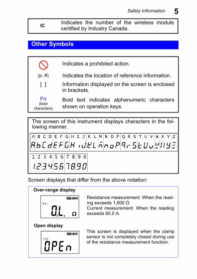
24Required Items:• Phillips screwdriver• LR6 alkaline battery (2)Normal procedure
Battery Status IndicatorThis indicator is displayed at the top right corner.?
1. Verify that the instrument is off.
2. Remove the fastening screws of the battery cover,using a Phillips screwdriver.
3. Remove the battery cover.
4. Insert two new batteries (LR06 alkaline batteries),taking care to orient them properly.
5. Replace the battery cover and tighten the fasteningscrews.
2
34
When new alkaline batteries have been installed
When 2/3 of the battery power remains
When 1/3 of the battery power remains
No battery power remains. Replace with new batteries.

2.3 Pre-Operation Inspection
252.3 Pre-Operation Inspection
Before using the instrument for the first time, verify that it oper-ates normally to ensure that no damage occurred during stor-age or shipping. If you find any damage, contact your dealer orHioki representative.
Does the screen turn on whenthe instrument is turned on?
The batteries may be dead.Replace the batteries and tryagain.
The instrument may be mal-functioning. Have the instru-ment repaired.
• Is the instrument damaged?• Is the clamp sensor cracked
or otherwise damaged?
No
End of inspection
Yes
An error isdisplayed.
• The screen is not on.• The screen shows an
error.
Do not use the instrument if itis damaged as doing so mayresult in electric shock. Havethe instrument repaired.
Yes
1. Inspecting the instrument
2. Inspecting the instrument after turning it on
The screen is on.Using the included resistancecheck loop to inspect the instru-ment (p.26)

2.3 Pre-Operation Inspection
26Before turning on the instrument, be sure to read Operating Pre-cautions (p.8).
Verify that there is no foreign matter lodged between the tips ofthe clamp sensor and that the sensor can be closed and openedsmoothly. If so, clamp the included resistance check loop andverify that the instrument is operating properly. Verify that avalue within the allowable range is displayed for each loop.
Using the included resistance check loop to inspect the instrument
Inspecting the instrument with the resistance check loop
Test resistance Allowable range
1 Ω 0.95 to 1.05 Ω
25 Ω 24.3 to 25.7 Ω
• If the instrument displays a value outside the allowablerange, it needs to be repaired. Contact your dealer orHioki representative.
• The resistance check loop cannot be used to calibratethe instrument. To have the instrument calibrated, con-tact your dealer.
Resistance check loop

2.4 Measurement Procedure
272.4 Measurement Procedure
• To avoid electric shock, do not touch the por-tion beyond the protective barrier during use.
• When the clamp sensor is opened, do notallow the metal part of the clamp to touchany exposed metal, or to short between twolines, and do not use over bare conductors.
• The maximum allowable current is 100 A ACcontinuous or 200 A AC for 2 minutes (50/60 Hz). Currentsin excess of these values must be avoided as they maydamage the instrument or cause bodily injury.
• The tips of the clamp sensor are precisely manufac-tured in order to provide a high level of precision. Exer-cise caution when handling the clamp so as to avoidsubjecting it to excessive vibration, mechanical shock,or force.
• If foreign matter gets stuck between the tips of theclamp sensor, do not forcibly open or close the sensor,but rather use a soft brush or similar implement tocarefully remove the foreign matter. Accurate mea-surements cannot be made while foreign matter isstuck between the tips of the clamp sensor or while theshape of the clamp sensor is deformed. If the tips ofthe clamp sensor become deformed, have the instru-ment inspected and calibrated by your dealer.
barrier

2.4 Measurement Procedure
28As illustrated below, the instrument is designed to measuregrounding resistance at multiple grounding locations. (*For appli-cations involving the measurement of grounding resistance at asingle grounding site, use Hioki’s 3151 EARTH HiTESTER.)
If the grounding resistance of the measurement target is repre-sented by Rx and the grounding resistance values of othergrounded locations are represented by R1, R2, …, Rn, the resis-tance value measured by the product is as follows:
If n is sufficiently large and each Ri value is sufficiently small, and the second term can be ignored, allowing the value of Rx to be measured.
Resistance Measurement
Measuring Principle
Rm Rx 11Ri-----
i 1=
n
------------------+=
Rx1
1Ri-----
i 1=
n
------------------»
Rx R1 RnR2

2.4 Measurement Procedure
29The following provides an example with actual measured values.The more grounding electrodes there are in the multiple-grounded installation, the higher the accuracy of the obtainedvalues. Alternately, if even one grounding electrode has a smallvalue (for example, 1 Ω), accurate values can be approachedeven if there are few grounding electrodes. Since most multiple-grounded systems have a large number of grounding elec-trodes, the error can be limited.
Example with actual measured values
Measuring method
1. Select resistance measurement mode.Select resistance measurement mode with the A/Ω key.
2. Clamp the grounding wire you wish to measure.The resistance value will be displayed.
Rx R1 Rn
Rx

2.4 Measurement Procedure
30• Verify that the mark is not lit up. When the current flowing through the grounding wire is high(approximately 2.5 A or greater with a commercial frequencyof 50/60 Hz), the current will affect measured values, makingit impossible to measure the resistance. Check the currentflowing through the grounding wire.
• Open displayThe screen will show [OPEn] if the clamp is not com-pletely closed. Close the clamp completely and repeatthe measurement.*If an extremely large current is flowing through thegrounding wire, the screen may display [OPEn] evenif the clamp is completely closed. This does not signala malfunction. Check the current flowing through thegrounding wire by using the instrument’s current mea-surement mode.
• Inductor and capacitor marksIf the [ ] marks next to the resistance mark light upduring measurement, the grounding resistance includesan in-series L or C component. If the [ ] mark is shownwith an extremely small measured value such as 0.1 Ω,the instrument may be unable to measure the groundingresistance because the grounding wire itself has formed aloop. If the [ ] mark lights up, there may be a break inthe loop. (In this case, the wires are being coupled bycapacitance.) In either of these cases, it is recommendedto verify that there is neither a short nor a wiring break inthe location being measured.
• Do not measure the same location with two or moreClamp On Earth Testers at the same time. The instru-ments will interfere with each other, preventing accu-rate measurement.

2.4 Measurement Procedure
31Current Measurement
1. Select current measurement mode with the A/Ω key.
2. Position the conductor in the center of the clampsensor.
3. The current RMS value will be shown on the display.

2.4 Measurement Procedure
32• The frequency of special waveforms such as at thesecondary side of an inverter may not be indicated cor-rectly.
• Depending on the magnitude and frequency of theinput current, resonances may be heard from theclamp jaw. This does not affect the measurement.
• Do not input a current in excess of the maximum allow-able current for the current range being used.
OK NG

2.4 Measurement Procedure
33When measuring zero-phase current, clamp all of the circuits atonce.
Measuring zero-phase current
Single-phase, 2-lead circuits
three-phase 3-lead circuits
clamp all three leads of thecircuit
Load device
Loaddevice
lg

2.4 Measurement Procedure
34Do not input current that exceeds the maximum continu-ous input of the electric current range.• Measurement may not be accurate in the cases below.(1) When there is large current (of about 100 A) flow-ing through a nearby electric line
(2) Note that a value of several tens of amperes maybe displayed when opening or closing the clampsensor, or when changing the electric currentrange. This is not an error. It may take some timefor the display to return to zero. However, startingmeasurement before the display returns to zero willnot affect measurement.
• Enable the "Filter function (Rejecting noise) (p.36)"when conducting measurement in the cases below.(1) When meaningless data is displayed due to noise.(2) When using the instrument to measure special
waveforms, such as those on the secondary side ofan inverter
The instrument may not be able to perform measure-ment in the cases below.
(1) When using input current that is 1/10 or less of thefull electric current range
(2) When measuring high frequencies with the filterfunction enabled.

2.5 Convenient function
35This function holds the measured value and continues to displaythat value. Press the HOLD key. The instrument will beep twice and the[ ] mark will be displayed, and the measured value will beheld. The HOLD key will flash. To cancel hold mode, press theHOLD key again. The instrument will beep once and the [ ]mark will disappear, and the HOLD key will stop flashing.
This function makes the display easier to see in dark locations. Press the BACKLIGHT key ( ). The backlight will turn on. The backlight will turn off automatically when there has been nooperation for about 2 minutes.To turn off the backlight, press the BACKLIGHT key ( ) again.The backlight will turn off.
2.5 Convenient function
Data hold function (Holding the measured value)
Backlight function(Making measurements in a dark location)
2.5 Convenient function
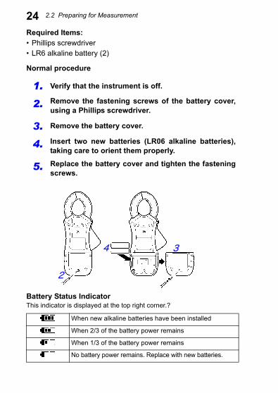
36This function allows you to reject unneeded frequency compo-nents such as high-frequency noise. Press the FILTER key. The [ ] mark will be displayed. Tocancel the filter, press the FILTER key again. The [ ] markwill disappear.
Filter function (Rejecting noise)
During resistance measurement
Using the filter function when there is a significant amountof variation in measured values during resistance measure-ment will cause the measured values to stabilize.*Note that noise rejection cannot be used when the [ ]mark is lit up.
During current measurement
Using the filter function enables a low-pass filter, causingthe harmonic component to be eliminated from measuredvalues. Widespread use of switching power supplies andinverters has led to cases where harmonic components aresuperimposed on current waveforms; the filter function iseffective in such cases. Canceling the filter function dis-ables the low-pass filter, allowing measurement of currentincluding harmonic components.

2.5 Convenient function
37You can sound an alarm (A high tone signifies a high alarm,while a low tone signifies a low alarm.) using previously setthresholds by pressing the key. Thresholds and other settings must be configured in advance.To cancel the alarm function, press the key again.
Alarm function (Judging measured values and sounding an alarm)
1. Configuring the alarm settings
Press the Fn key to switch to function mode. Using the and keys, select the resistance or current Alarm Settingsscreen and press the OK key.*For more information about function mode, see (p.52).
Alarm Settings screen for resistance measurement
Alarm Settings screen for current measurement

2.5 Convenient function
382. Set the alarm type (Hi/Lo).
Using the and keys, select the alarm type (Hi/Lo), andpress the OK key. The next threshold setting will start flash-ing.
Lo: The alarm will sound if the measured valueis less than the set threshold value.
Hi: The alarm will sound if the measured valueis greater than the set threshold value.
*The Hi/Lo setting is saved once the following setting has beenconfigured. If you press the Fn key after configuring the Hi/Lo set-ting but before saving the threshold and thereby cancel the config-uration process, any changes to the Hi/Lo setting will not besaved.

2.5 Convenient function
393. Set the threshold.
After configuring the Hi/Lo setting, set the threshold. Using the and keys, set the threshold and press theOK key.You can move more quickly through threshold values bypressing and holding the and keys.
Once the settings are complete, the screen will switch tothe Alarm Settings screen. To return to resistance mea-surement or current measurement mode, press the Fn keyagain or the A/Ω key.

2.5 Convenient function
40Press the MEM key in either resistance measurement mode orcurrent measurement mode. The instrument will beep threetimes and the displayed measured value will be stored alongwith the memory number (1 to 2,000) in the instrument’s internalmemory.
* Measured values, filter use, and the [ ] and [ ]marks are saved in memory.
Memory function (Saving measurement data)
Memory number
When the number of values saved in the instrument’s memoryreaches 2,000, the display will show “FULL,” and you will notbe able to save additional values. Delete unneeded values tofree up space.

2.5 Convenient function
41Loading a value from the instrument’s internal memory
1. Press the Fn key to enter function mode. Using the and keys, select the Read Memoryscreen and press the OK key.*For more information about function mode, see (p.52).
2. Using the and keys, increment or decrement thememory number to recall the measured value for thememory number you wish to load.You can move more quickly through memory numbersby pressing and holding the and keys.
To exit the Read Memory screen, press the Fn key orthe OK key. * To return to resistance measurement or current mea-
surement mode, press the Fn key again or the A/Ωkey.

2.5 Convenient function
42Clearing stored data
You can clear the last stored data point (1 value) or allstored data points.
1. Press the Fn key to enter function mode. Using the and keys, select the Clear Memoryscreen and press the OK key. The screen will show[CLr].*For more information about function mode, see (p.52).
2. Using the and keys, select either the last storeddata point or all data points and press the OK key.
To clear the last stored data point(1 value)(The screenshot to the left indicatesthat 34 values have been saved inthe instrument’s memory.)
To clear all data points(The screen will show [ALL].)

2.5 Convenient function
43The [OK?] mark will flash on the LCD once you selectthe data to clear so that you can confirm your intentions.Press the OK key again to clear the data.• To cancel, press the Fn key.• To return to resistance measurement or current mea-
surement mode, press the Fn key again or the A/Ωkey.

2.5 Convenient function
44By enabling the FT6381’s Bluetooth® function, you can transfermeasurement data to an Android™ handset to create measure-ment reports. For more information, refer to the help function ofthe FT6381 Communication Software, an app for Android™handsets.
In addition to installing the application, the following two sets ofconnection settings must be configured in order to use the Blue-tooth® function:
• Pairing the Android™ handset and FT6381• Registering the FT6381 connection with the FT6381 Commu-
nication Software
Use the following procedure to configure the connection settings:
Making measurements with an Android™ handset (FT6381 only)
Measurement process
1. Enable the FT6381’s Bluetooth® function. (p.45)
2. Pair the instrument with the Android™ hand-set.
(p.46)
3. Install the FT6381 Communication Softwareon the Android™ handset.
(p.47)
4. Register the instrument you wish to connectwith the FT6381 Communication Software.
(p.48)

2.5 Convenient function
45Enabling the Bluetooth® function on the FT6381
1. Press the Fn key to enter function mode.* For more information about function mode, see (p.52).
2. Using the and keys, select the Bluetooth® Settingscreen and press the OK key.
Using the and keys, select “on” on the Bluetooth®
Setting screen and press the OK key to enable the Blue-tooth® function.
Use of Bluetooth® functionality shortens the battery lifecompared to normal use. It is recommended to turn offBluetooth® functionality when not in use.

2.5 Convenient function
46Pairing the instrument with an Android™ handset (first use only)
1. Select [Wireless and Networks] from the Android™handset’s Settings button.
2. After enabling the Bluetooth® function, select [Scan fordevices] from [Bluetooth settings] (exact words varieswith the specific Android™ handset being used; variantsinclude “Search for devices” and “Detect nearby terminals”).
3. When the handset discovers [FT6381#XXXXXXXXX] (where“XXXXXXXXX” is the serial number found on the back of theinstrument), pair the instrument. Note that previously paired devices may appear in a separatecolumn labeled with language such as “Paired devices” ratherthan in the search results.
4. Enter [0000] as the PIN number.
0000
Pairing is only necessary the first time you use the instru-ment with the handset. When using multiple FT6381 instru-ments, you will need to pair each instrument.
2
4 Enter3

2.5 Convenient function
47*The screen contents vary with the specific Android™ handsetbeing used. For more information about Bluetooth® device pair-ing methods and related procedures, see your Android™ hand-set’s instruction manual.Search for “FT638” on the Google Play™ store and downloadand install the FT6381 Communication Software.A Google account is required in order to download applicationsfrom the Google Play™ store. For more information about howto register for a Google account, contact the store from whichyou purchased the Android™ handset.
Installing the FT6381 Communication Software on the Android™ handset
Enter and search.
Download

2.5 Convenient function
48Once the instrument has been paired, it will connect automati-cally, and FT6381 measured values will be sent to the Android™handset in real time. The instrument will not be able to connectto the handset if it has not been paired. Refer to "Pairing theinstrument with an Android™ handset (first use only) (p.46)" topair the instrument.
The application is free, but the user is responsible forany Internet connection costs incurred in the course ofdownloading or using the application. Since such costsmay be incurred during use of the application, it is rec-ommended to use a fixed-price plan. Hioki is not liablefor any Internet connection costs.
Registering the instrument you wish to connect with the FT6381 Communication Software
1. Turn on the FT6381. Launch the FT6381 Communication Software on theAndroid™ handset. If you wish to use the map function,enable the GPS function.
2. From the list of Bluetooth® devices, select [FT6381#XXXXXXXXX] and press the [Settings] button. TheFT6381 will be registered.
Select

2.5 Convenient function
49• The screen contents vary with the specific Android™handset being used. For more information about Blue-tooth® device pairing methods and related procedures,see your Android™ handset’s instruction manual.
• Communications between the FT6381 and Android™handset are limited to a range of about 10 m, butobstacles (walls, metal shielding, etc.) can shortenthis distance or prevent communications from beingestablished.
• The FT6381’s wireless function uses Bluetooth® wire-less technology that utilizes the 2.4 GHz band. It maynot be possible to establish communications if there isa wireless LAN (IEEE 802.11.b/g/n) or other network/device using the same frequency band nearby.
• The application supports Android OS 2.1 or later, butproper operation is not guaranteed on all Android™handsets. For more information about the devices onwhich proper operation has been confirmed, seeHioki’s website.
• Adobe’s Adobe Reader, which is available free ofcharge on the Google Play™ store, is required inorder to view PDF reports. Install the applicationbefore attempting to view reports.
• The confidentiality of information contained in Blue-tooth® communications sent from the FT6381 is notguaranteed. Hioki is not liable for any unauthorizeddisclosure or other issue with measured valuescaused by Bluetooth® communications.
• The FT6381 can only be used in Japan, the U.S., Can-ada, and the EU. Because it incorporates Bluetooth®
wireless technology, the instrument emits radio radia-tion. Use of devices that emit radio radiation requiresapproval in the country of use, and use of the instru-ment in a country or region other than those listedabove may be subject to penalty as a violation of law.

2.5 Convenient function
50After turning on the FT6381, launch the FT6381 CommunicationSoftware on the Android™ handset. If you wish to use the mapfunction, enable the GPS function. Once the instrument hasbeen paired, it will connect automatically, and FT6381 measuredvalues will be sent to the Android™ handset in real time. Theinstrument will not be able to connect to the handset if it has notbeen paired. Refer to "Pairing the instrument with an Android™handset (first use only) (p.46)" to pair the instrument.
If you have multiple FT6381 instruments and wish to change theunit to connect to the handset, press the Settings button afterpressing the menu button on the Android™ handset and recon-figure the Bluetooth® device settings.
Check the following if you are unable to establish a Bluetooth®
connection between the FT6381 and the Android™ handset:
• Is the Bluetooth® function enabled on both the Android™handset and the FT6381?
• Has the FT6381 in question been paired on the Android™handset’s Bluetooth® settings screen? If the instrument hasnot been paired, refer to "Pairing the instrument with anAndroid™ handset (first use only) (p.46)" to pair it.
Using the FT6381 Communication Software (second and subsequent use)
Switching the FT6381 to connect with the Android™ handset
If you are unable to establish a Bluetooth® connection

2.5 Convenient function
51The application provides the following functionality:
For more information about the FT6381 Communication Soft-ware application, refer to the application help.
About the FT6381 Communication Software
Sending measurement data (from the LCD display) to theAndroid™ handset in real time
Saving and viewing measurement data (including timestamp, GPS position data for the measurement location,and map data)
Creating reports from measurement data• Single reports created from measurement data from one
location• Summary reports that present a summary of multiple sets
of measurement data (with the ability to add commentsand change header and footer information)
Outputting measurement data as a CSV file
Sending measurement data as an e-mail
Downloading the contents of the FT6381’s internal memory

2.5 Convenient function
52In function mode, the following settings and operations are available:
Function mode
• Resistance alarm settings • Current alarm settings• Loading values from memory • Clearing data from the instrument’s
memory• Bluetooth® setting
Current alarm settings (p.31)
Loading values from memory (p.41) Clearing data from the instrument’s memory (p.42)
Resistance Alarm Settings (p.29)
2. 3. 1. While in function mode, the [ ]mark will light up.
1. Press the Fn key to enter func-tion mode.
2.Using the and keys, se-lect the desired setting.
3.Accept the setting with the OKkey.
Press the Fn key or the A/Ω keyto exit function mode.
*FT6381 only
Bluetooth® Setting (p.44)

2.6 Advanced Settings and Functions
53Advanced settings can be configured in sub-function mode. Insub-function mode, the following settings and operations areavailable:
• Measurement range display setting (p.54)• Auto-power-saving (APS) setting (p.55)• System reset (to revert to factory settings) (p.56)
To enter sub-function mode, turn on the instrument by pressingthe POWER key while holding down the Fn key.
To exit sub-function mode, press the POWER key to turn off theinstrument and then turn it back on.
2.6 Advanced Settings and Functions
Press the POWER keywhile holding down theFn key.
1
2

2.6 Advanced Settings and Functions
54Enabling/disabling the measurement range display function
1. Enter sub-function mode.Press the POWER key while holding down the Fn key.
2. Using the and keys, select the Range Display Settingscreen and press the OK key.
3. Using the and keys, switch the range display functionon or off and press the OK key.
The measurement range is displayed using values only.(Example: 1,600 Ω range 1,600) The units for the measurement range are the same asfor the displayed measured value.

2.6 Advanced Settings and Functions
55The auto-power-saving (APS) function prevents unintentionalbattery consumption when you forget to turn off the instrument.The APS function activates automatically when the instrument isturned on. The instrument will automatically turn off once about5 minutes pass without any operation (an alarm will sound forabout 10 seconds first). Pressing any key while the alarm sounds will reset the timebefore the instrument turns off to about 5 minutes.
Enabling/disabling the auto-power-saving (APS) function
1. Enter sub-function mode.Press the POWER key while holding down the Fn key.
2. Using the and keys, select the APS Setting screenand press the OK key.
3. Using the and keys, switch the APS function on or offand press the OK key.When the APS function is disabled in sub-function mode,APS will remain disabled when the instrument’s power iscycled.
The APS function is enabledwhen the screen shows [on].

2.6 Advanced Settings and Functions
56This section describes how to initialize the instrument’s settings.All measurement data (up to 2,000 values) will be deleted.
To disable APS temporarily
Turn on the instrument by pressing the POWER keywhile holding down the HOLD key to disable APS untilthe next time the instrument’s power is cycled. The nexttime the power is cycled, APS will be enabled (as longas the APS setting is enabled in sub-function mode).
Reverting the instrument to factory settings (system reset)
1. Enter sub-function mode. Press the POWER key while holding down the Fn key.
2. Using the and keys, select the System Reset screenand press the OK key. The [OK?] mark will flash.
3. Press the OK key again. The instrument will revert to the fac-tory settings.
• If the System Reset screen is displayed by mistake,cycle the instrument's power without pressing the OKkey. Instrument operation will be restored without asystem reset having been performed.
• For more information about how to clear previously savedmeasurement data, see "Clearing stored data (p.42)".

3.1 Measurement Specifications
57Specifications Chapter 3
3.1 Measurement Specifications
Common measurement specifications
Guaranteed accuracy period
1 year (Opening and Closing of the Sensor: Maximum 10000times)
Accuracy guaran-tee for tempera-ture and humidity
23°C±5°C (73°F±9°F) 80%RH or less (non-condensation)
Temperaturecharacteristics
-10 to 50°C Measurement accuracy x 0.1/°C (except 23°C±5°C)
Maximum rated voltage to earth
600 VAC measurement category IV (ant ic ipated t ran-sient overvoltage 8000 V)
Resistance measurement specifications
Guaranteed accuracy conditions
No reactance component, no noise current
Effective measuring range
0.02 Ω to 1600 Ω
Zero suppression Less than 0.02 Ω
Overrange Greater than 1600 Ω
MeasurementMethod
Analog synchronous detection method (effective resistance mea-surement)
Injected signal frequency
Approx. 2.4 kHz
Injected voltagelevel
Approx. 9.0 mV (with load open)

3.1 Measurement Specifications
58*To obtain the measurement accuracy at a range boundary, apply the accuracy of thehigher-accuracy range.
Range(Accuracy Range)
Resolution Accuracy
0.20 Ω (0.02 Ω to 0.20 Ω) 0.01 Ω ±1.5%rdg.±0.02 Ω
2.00 Ω (0.18 Ω to 2.00 Ω) 0.01 Ω ±1.5%rdg. ±0.02 Ω
20.00 Ω (1.80 Ω to 20.00 Ω) 0.01 Ω ±1.5%rdg.±0.05 Ω
50.0 Ω (18.0 Ω to 50.0 Ω*) 0.1 Ω ±1.5%rdg.±0.1 Ω
100.0 Ω (50.0 Ω* to 100.0 Ω*) 0.1 Ω ±1.5%rdg.±0.5 Ω
200.0 Ω (100.0 Ω* to 200.0 Ω) 0.2 Ω ±3.0%rdg.±1.0 Ω
400 Ω (180 Ω to 400 Ω*) 1 Ω ±5%rdg.±5 Ω
600 Ω (400 Ω* to 600 Ω*) 2 Ω ±10%rdg.±10 Ω
1200 Ω (600 Ω* to 1200 Ω*) 10 Ω ±20%rdg.
1600 Ω (1200Ω* to1600 Ω) 20 Ω ± 35%rdg.

3.1 Measurement Specifications
59Current measurement specificationsGuaranteed ac-curacy conditions
Sine wave input
Measurementmethod
Digital sampling method (true RMS measurement)
Crest factor 5.0 or less (for the 60 A range, 1.7 or less)
Conductor position effects
Within ±0.5% rdg. (using the center of the sensor as the reference,in all positions)
Magnetic field interference
10 mA or less in an external magnetic field of 400 A/m at 50/60 HzAC
Maximum allow-able input
100 A AC continuous, 200 A AC for 2 minutes (50/60 Hz)For frequency derating characteristics during continuous input, seethe following diagram:
Effective measuring range
0.05 mA to 60.0 A
Zero-suppression Less than 0.05 mA
Overrange Greater than 60.0 A
Frequency [Hz]
Gai
n [d
b]

3.1 Measurement Specifications
60Range(Accuracy Range)
Resolu-tion
Guaranteed accuracy
frequency range
Accuracy
Filter off Filter on
20.00 mA(1.00 mA to 20.00 mA)
0.01mA
45 f 66 Hz±2.0%rdg.±0.05 mA
±2.0%rdg.±0.05 mA
30 f < 45 Hz66 < f 400 Hz
±2.5%rdg.±0.05 mA
--
200.0 mA(18.0 mA to 200.0 mA)
0.1mA
45 f 66 Hz±2.0%rdg.±0.5 mA
±2.0%rdg.±0.5 mA
30 f < 45 Hz66 < f 400 Hz
±2.5%rdg.±0.5 mA
--
2.000 A(0.180 A to
2.000 A)0.001 A
45 f 66 Hz±2.0%rdg.±0.005 A
±2.0%rdg.±0.005 A
30 f < 45 Hz66 < f 400 Hz
±2.5%rdg.±0.005 A
--
20.00 A(1.80 A to 20.00 A)
0.01 A
45 f 66 Hz±2.0%rdg.±0.05 A
±2.0%rdg.±0.05 A
30 f < 45 Hz66 < f 400 Hz
±2.5%rdg.±0.05 A
--
60.0 A(18.0 A to
60.0 A)0.1 A
45 f 66 Hz±2.0%rdg.
±0.5 A±2.0%rdg.
±0.5 A
30 f < 45 Hz66 < f 400 Hz
±2.5%rdg.±0.5 A
--

3.2 General Specifications
613.2 General Specifications
Location for use Pollution Degree 2, altitude up to 2000 m (6562-ft.)
Storage temperatureand humidity
-20 to 60°C (-4.0°F to 140°F), 80%RH or less (non-condensation,except for the battery)
Operating temperature and humidity
Temperature : -10 to 50°C (14°F to 122°F)Humidity : 80%RH or less (non-condensation)
Dielectric strength Between the Case and the Clamp core 7400 Vrms 1 minute
Applicable standards
Safety : EN61010EMC : EN61326Page 64Effects of radiated, radiofrequency, electromagnetic field: At 3 V/m,5X accuracy specifications or less (resistance measurement)WirelessJapan (type certification) 001-X00013US (FCC) Part 15.247 (FCC ID: QOQWT12)Canada (IC) RSS-210 (IC: 5123A-BGTWT12A)EU EN 300 328
EN 301 489-1EN 301 489-17
Dust and waterprotection
IP40 (EN60529)*With clamp sensor closed.
Power supply LR06 alkaline battery × 2 (3 VDC)
Maximum ratedpower
450 mVA
Continuous operating time
Approx. 35 hours (25 Ω measurement, backlight off,Bluetooth® OFF (Model FT6381), 23°C reference
Dimensions Approx. 73 W×218 H×43 D mm (2.87”W×8.58”H ×1.69”D) (exclud-ing projections)
Maximum measurable con-ductor diameter
φ32 mm
Mass Approx. 620g (21.9 oz) Except for the battery
Accessories Carrying case (1), Resistance check loop (1), Strap (1), LR06 alkaline battery × 2, Instruction manual (1)
Display specifications
LCD display Max. 2,000 count
Display refreshrate
Approx. 2 times/sec.

3.2 General Specifications
62Range switching Auto-rangeOverrange display
[O.L] display
Data hold display
mark lights up.
Function modedisplay
mark lights up. Flashes in subfunction mode.
Filter display mark lights up.
Auto-power-savedisplay
mark lights up
Remaining battery display
Display of remaining battery power in 4 stages ( )
Memory numberdisplay
mark lights up.
Range display mark lights up.
Alarm display mark lights up.
Confirmation ofmemory erasureand reset operation
mark lights up.
Noise mark display
mark lights up.(When there is a superimposed noise current during resistancemeasurement, accuracy cannot be guaranteed.)
mA/A unit display
mA mark or A mark lights up.
Ω unit display Ω mark lights up.
AC current markdisplay
mark lights up (during AC current measurement).
Resistance markdisplay
mark lights up (during resistance measurement).
Inductance markdisplay
mark lights up (when the phase angle θ > approx. 45° dur-ing resistance measurement).
Capacitancemark display
mark lights up (when the phase angle θ < approx. -45° dur-ing resistance measurement).
Bluetooth® display
Bluetooth® function off: mark turns off (Model FT6381).Bluetooth® function on/communications inactive: mark lights up(Model FT6381).Bluetooth® function on/communications active: mark flashes(Model FT6381).

3.2 General Specifications
63Function specifications (underline: default value)Data hold functionBacklight functionAutomatically turns off approx. 2 min. after last key operation.
Filter function
Resistance measurement filter function
Moving average time: Max. 9 sec.
Current measurement filter function
Cutoff frequency: 180 Hz ±30 Hz (-3 dB)
Alarm function
Resistance alarmfunction
Resistance measurement mode alarm: Beeps when measured value is less than or greater than threshold.
Current alarm function
Current measurement mode alarm: Beeps when measured valueis less than or greater than threshold.
Alarm Hi/Lo Separate Hi/Lo settings for resistance measurement and currentmeasurementResistance measurement: Hi.AL/Lo.ALCurrent measurement: Hi.AL/Lo.AL
Alarm thresholdsetting range
Resistance measurement: 0.02 Ω to 1,600 ΩResistance measurement initial value: 25.0 ΩCurrent measurement: 0.05 mA to 200.0 mA, 0.201 A to 60.0 ACurrent measurement initial value: 1.00 mA
Memory function
Memory capacity 2,000 values
Auto-power-savefunction
Instrument automatically turns off approx. 5 min. after last key operation.
Function mode
Moving betweenitems
After selecting setting item with and keys, accept with OKkey.
Resistance alarmfunction
AL Ω: Resistance Hi/Lo, threshold settings
Current alarmfunction
AL A: Current Hi/Lo, threshold settings
Loading memoryvalues
MEM READ: Load memory values.
Clearing memory values
MEM CLR: Clear last saved memory value or all values.
Bluetooth® operating setting
BT: ON/OFF (FT6381)

3.2 General Specifications
64Sub-function modeRange displayfunction
RNG: ON/OFF
Auto-power-savefunction
APS: ON/OFF
System reset SYS RST
Bluetooth® function
Displays measured values on the screen of an Android™ handsetvia Bluetooth®.

4.1 Cleaning
65Maintenance and Service Chapter 4
4.1 Cleaning
If foreign matter gets stuck between the tips of the clamp sen-sor, do not forcibly open or close the sensor, but rather use asoft brush or similar implement to carefully remove the foreignmatter. Accurate measurements cannot be made while foreignmatter is stuck between the tips of the clamp sensor or while theshape of the clamp sensor is deformed. If the tips of the clampsensor become deformed, have the instrument inspected andcalibrated by your dealer.
• Wipe the LCD gently with a soft, dry cloth.• To clean the instrument, wipe it gently with a soft cloth
moistened with water or mild detergent. Never use sol-vents such as benzene, alcohol, acetone, ether,ketones, thinners or gasoline, as they can deform anddiscolor the case.

4.2 Troubleshooting
66Transporting• When sending the instrument for repair, remove the batteries
and pack carefully to prevent damage in transit. Include cush-ioning material so the instrument cannot move within the pack-age. Be sure to include details of the problem. Hioki cannot beresponsible for damage that occurs during shipment.
• Use the original packing materials when transporting theinstrument, if possible.
4.2 Troubleshooting
Inspection and Repair
If damage is suspected, check the "Before returning forrepair" section before contacting your dealer or Hiokirepresentative.
Before returning for repair
Symptom Cause Remedy
No screen is dis-played evenwhen the instru-ment is turned on.
• Are the batteriescorrectly inserted?
• Is the useful bat-tery life at an end?
Insert the new batter-ies.(p.23)
The screen turnsoff after a littlewhile.
• Is the useful bat-tery life at an end?
• Has the APS func-tion been trig-gered?
(p.55)

4.3 Error Display
67If an error is shown on the LCD, the instrument needs to berepaired. Contact your dealer or Hioki representative.
4.3 Error Display
Error Display Meaning Remedial Action
E001 Main CPU program error
Please contact your dealeror Hioki representative.
E002 Sub CPU program error
E003 EEPROM R/W error
E004 Adjustment data error

4.3 Error Display
68