Embed Size (px)
Citation preview

TECHNO – FEASIBILITY STUDY 2016
P R E P A R E D B Y : C O N V E Y O R & R O P E W A Y S E R V I C E S P V T . L T D . Page 1
HIMACHAL PRADESH POWER CORPORATION LTD. HIMACHAL PRADESH
TECHNO – FEASIBILITY STUDY FOR
INSTALLATION OF 6 Nos. MATERIAL ROPEWAYS
FOR CHANJU III HEP (48 MW)
AT CHURAH TEHSIL DISTT. CHAMBA, HIMACHAL PRADESH
YEAR 2016
DETAILED PROJECT REPORT
PREPARED BY CONVEYOR & ROPEWAY SERVICES PVT. LTD.
75C, PARK STREET, 6TH
FLOOR KOLKATA – 700 016

TECHNO – FEASIBILITY STUDY 2016
P R E P A R E D B Y : C O N V E Y O R & R O P E W A Y S E R V I C E S P V T . L T D . Page 2
CONFIDENTIALITY OF THE DOCUMENT
THIS DOCUMENT IS THE OUT COME OF THE
STUDY FUNDED BY HPPCL AND, THEREFORE,
IS THE PROPERTY OF HPPCL.
NO PART OR WHOLE OF THIS DOCUMENT
SHALL BE REPRODUCED, COPIED, LOANED OR
DISPOSED DIRECTLY OR INDIRECTLY, NOR BE
USED FOR ANY PURPOSE OTHER THAN THAT
FOR WHICH IT IS SPECIFICALLY PREPARED
WITHOUT THE PRIOR PERMISSION OF HPPCL.

TECHNO – FEASIBILITY STUDY 2016
P R E P A R E D B Y : C O N V E Y O R & R O P E W A Y S E R V I C E S P V T . L T D . Page 3
ACKNOWLEDGEMENT
WE ACKNOWLEDGE WITH SINCERE & DEEP GRATITUDE
TO THE OFFICIALS OF HPPCL, WHO WERE DIRECTLY OR
INDIRECTLY INVOLVED, FOR THEIR CO-OPERATION AND
SUPPORT EXTENDED TO THE TEAM FROM CONVEYOR &
ROPEWAY SERVICES PVT. LTD. DURING THE COURSE
OF EXECUTING THIS ASSIGNMENT WITHOUT WHICH
THIS REPORT COULD NOT HAVE BEEN SUCCESSFULLY
PREPARED. WE ARE ALSO INDEBTED TO THEIR
VALUABLE ADVICES

TECHNO – FEASIBILITY STUDY 2016
P R E P A R E D B Y : C O N V E Y O R & R O P E W A Y S E R V I C E S P V T . L T D . Page 4
INDEX
Chapter Description Page No. LIST OF TABLES 5
LIST OF DRAWINGS 6
LIST OF ANNEXURES 7
ABBREVIATIONS 8
Preamble 9
Executive Summary 15
I Introduction 21
II Survey Work & Field Data Collection 24
III Aerial Ropeway System Description 28
IV Proposed or Recommended Ropeway
System 38
V Design parameters of Ropeway system 51
VI Plant Machinery for the proposed Ropeway System
60
VII Capital Investments Cost estimates 87
VIII Conclusion & Recommendation 90
IX Electrical System for power transmission and control etc.
91
X Annexure – 1 Codes & standards Annexure – 2 Annexure – 3
124 128 129

TECHNO – FEASIBILITY STUDY 2016
P R E P A R E D B Y : C O N V E Y O R & R O P E W A Y S E R V I C E S P V T . L T D . Page 5
LIST OF TABLES
1. Ropeway station Locations
2. Ropeway working Parameters

TECHNO – FEASIBILITY STUDY 2016
P R E P A R E D B Y : C O N V E Y O R & R O P E W A Y S E R V I C E S P V T . L T D . Page 6
LIST OF DRAWINGS
TITLE DRAWING NO.
PROPOSED LAYOUT OF SIX ROPEWAYS AT
CHANJU, H.P. : CRSPL-MKT-PD-013
PROPOSED PROFILE OF ROPEWAY -1 AT CHANJU, H.P.
: CRSPL-MKT-PD-014
PROPOSED PROFILE OF ROPEWAY -2 AT CHANJU, H.P.
: CRSPL-MKT-PD-015
PROPOSED PROFILE OF ROPEWAY -3 AT CHANJU, H.P.
: CRSPL-MKT-PD-016
PROPOSED PROFILE OF ROPEWAY -4 AT CHANJU, H.P.
: CRSPL-MKT-PD-017
PROPOSED PROFILE OF ROPEWAY -5 AT CHANJU, H.P.
: CRSPL-MKT-PD-018
PROPOSED PROFILE OF ROPEWAY -6 AT CHANJU, H.P.
: CRSPL-MKT-PD-019
SCHEMATIC DIAGRAM OF LOADING STATION : CRSPL-MKT-PD-011
SCHEMATIC DIAGRAM OF UNLOADING STATION : CRSPL-MKT-PD-012
SCHEMATIC ARRANGEMENT OF MATERIAL TROLLEY AND CARRIAGE
: CRSPL-MKT-PD-010
ARRGT OF TRESTLE DOUBLE TRACK BICABLE ROPEWAY
: 04.PD.STD.016

TECHNO – FEASIBILITY STUDY 2016
P R E P A R E D B Y : C O N V E Y O R & R O P E W A Y S E R V I C E S P V T . L T D . Page 7
LIST OF ANNEXURES
* CODES & STANDARDS – Annexure – I * TYPICAL CALCULATION SHEET FOR FOUNDATIONS – Annexure – 2 & 3

TECHNO – FEASIBILITY STUDY 2016
P R E P A R E D B Y : C O N V E Y O R & R O P E W A Y S E R V I C E S P V T . L T D . Page 8
ABBREVIATIONS
HPPCL : Himachal Pradesh Power Corporation Ltd. CRSPL : Conveyor & Ropeway Services Pvt. Ltd. GoHP : Himachal Pradesh State Government HPSEB : Himachal Pradesh State Electricity Board GPS : Geographical Positioning System NOCs : No Objection Certificates M : Meter MM : Millimeter Kgs : Kilograms MCC : Motor Control Centre R1 : Ropeway – 1 Chanju – III HEP (48 MW) R2 : Ropeway – 2 Chanju – III HEP (48 MW) R3 : Ropeway – 3 Chanju – III HEP (48 MW) R4 : Ropeway – 4 Chanju – III HEP (48 MW) R5 : Ropeway – 5 Chanju – III HEP (48 MW) R6 : Ropeway – 6 Chanju – III HEP (48 MW)
TECHNO – FEASIBILITY STUDY 2016
P R E P A R E D B Y : C O N V E Y O R & R O P E W A Y S E R V I C E S P V T . L T D . Page 9
PREAMBLE
Himachal Pradesh Power Corporation Limited (HPPCL) is a fast
upcoming power generating utility with all the Technical and
Organizational capabilities at par with other generating companies
like NTPC/SJVNL/NHPC. Efforts are afoot to further strengthen the
respective departments with professionals of proven credentials and
qualified technical manpower. The head office of Himachal Pradesh
Power Corporation Limited is at Shimla, Himachal Pradesh.
Himachal Pradesh Power Corporation Limited (HPPCL), was
incorporated in December 2006 under the Companies Act 1956, with
the objective to plan, promote and organize the development of all
aspects of hydroelectric power in Himachal Pradesh.
Against the above back drop, the Himachal Pradesh Power
Corporation Limited (HPPCL) has a proposal of installing 2 Hydro
Electric Projects, a) Chanju- III HEP (48MW) & b) Deothal- Chanju
HEP (30 MW) in Churah Tehsil of Distt. Chamba (HP). M/s HPPCL
decided to have a mechanized transportation system for transporting
the construction materials to the work site. To explore the Techno -
feasibility of installing aerial ropeway systems for transportation of
construction material for construction of those Hydro Electric Power
Projects, the company needed to hire the services of a consultancy
firm expertise in ropeway system and accordingly, invited EOI for the
consultancy job. After scrutiny the technical capacity and capability of
the firms, who had submitted their EOI, the company invited Bid/
quotation for the services. M/s Conveyor & Ropeway Services Pvt.
Ltd. (CRSPL), a specialist engineering organization engaged in

TECHNO – FEASIBILITY STUDY 2016
P R E P A R E D B Y : C O N V E Y O R & R O P E W A Y S E R V I C E S P V T . L T D . Page 10
Design, Manufacture, Supply, Erection, Commissioning, Operation
and Maintenance of Aerial Ropeway Systems, for both material and
Passenger transportation, had submitted their offer vide their letter
no. CRSPL/69/65/797/15-16/131 dt 05.10.2015 and clarification vide
their letter no. CRSPL/69/65/797/15-16/134 dt. 07.10.15. HPPCL
scrutinized the offer and issued LOA vide their letter No. HPPCL/GM-
TM&TPHEP’s/RCP-Civil/G-9/2015-1483-87 dt. 26.10.2015. After
agreed scope of work and terms & conditions of the project, HPPCL
entered into an contract agreement with CRSPL vide CONTRACT
AGREEMENT – Agreement No.: HPPCL/DGM/RCP/2015/5 dt.
07.11.2015.
In conformity, with the terms of the contract Agreement and the discussion held on 07.11.15, this Report has been prepared and submitted to the HPPCL by CRSPL. The scope of the work for this project included the following:
1. Reconnaissance tour at the area and selection of the best
possible Alignment and most appropriate ropeway system in
consultation with HPPCL.
2. Survey along the selected Alignment and preparation of Survey
drawings including L – Section through the Alignment.
3. Survey in and around the proposal Ropeway Terminal sites and
preparation of Contour Plan.
4. a) Chanju-III HEP (48 MW):

TECHNO – FEASIBILITY STUDY 2016
P R E P A R E D B Y : C O N V E Y O R & R O P E W A Y S E R V I C E S P V T . L T D . Page 11
Preparation of Technical Feasibility study report for construction
of 6 no. material ropeways for Chanju-III HEP (48 MW) of
HPPCL in Churah Tehsil of Chamba District.
b) Deothal Chanju HEP (30 MW)
Alternative – I:
Preparation of Techno-Economic Feasibility study report for
construction of 5 no. material ropeways across the nallah and
one no ropeway longitudinally along the right bank of Deothal
nallah passing through all the take off points of all ropeways
and up to trench Weir for Deothal Chanju HEP (30 MW) of
HPPCL in Churah Tehsil of Chamba District.
Alternative –II:
Preparation of Techno-Economic Feasibility study report for
construction of 1 no. material ropeways across the nallah from
right bank to adit to forebay and further one no. ropeway
longitudinally along left bank of Deothal nallah passing through
all adits portals and up to trench weir for Deothal Chanju-III HEP
(30 MW) of HPPCL in Churah Tehsil of Chamba District.
5. The ropeway shall be used for transportation of construction
material i.e. cement, steel reinforcement in cut lengths, steel
ribs, aggregates, steel liner etc. and the machinery / equipment
i.e. welding sets, tipping trolleys, air compressor, concrete
mixtures, concrete placers, air receiver tank, drilling equipment
etc. in parts. Load carrying capacities of the ropeways and
location / number of supporting structures shall be finalized in
consultation with HPPCL.

TECHNO – FEASIBILITY STUDY 2016
P R E P A R E D B Y : C O N V E Y O R & R O P E W A Y S E R V I C E S P V T . L T D . Page 12
6. Preparation of Ropeway Profile Drawing including tentative
location of Intermediate Towers.
7. Preliminary Design of the Ropeway, Stations and towers
including selection of Rope, Drive etc.
8. Working out Estimated Cost
9. Submission of a Consolidated Report with necessary Drawings,
Sketches, Charts, Calculation etc.
In executing the study, the following were identified as the
responsibilities of M/s Conveyor & Ropeway Services Pvt. Ltd.
(CRSPL)
1. Deployment of requisite manpower for Survey and other field
work to complete the scope of work in all respect.
2. Deployment of necessary Survey and other measuring
instruments to complete the scope of work in all respect.
3. Submission of the technical feasibility study reports in 5 (Five)
sets hard copies.

TECHNO – FEASIBILITY STUDY 2016
P R E P A R E D B Y : C O N V E Y O R & R O P E W A Y S E R V I C E S P V T . L T D . Page 13
At the same time, HPPCL agreed to take up the following
responsibilities:
1. To obtain and provide permission from Competent Authority for
Survey Work as also for cutting of small trees, bushes etc.
2. Identify a suitable location to be selected as the Loading Station
and unloading station.
3. To provide accommodation of the Field Engineers/Staff close to
the work sites on chargeable basis.
4. To assign one authorized person to provide all required
information and assisting the Field Team, if needed any.
. ******************

TECHNO – FEASIBILITY STUDY 2016
P R E P A R E D B Y : C O N V E Y O R & R O P E W A Y S E R V I C E S P V T . L T D . Page 14
Methodology CRSPL mobilized a technical team to carry out the survey of the
profile along the tentative alignment based on the freezing of loading
stations and the unloading stations. During this exercise, the team
picked-up the geodetic co-ordinates of the locations (elevation,
longitude & latitude readings) along the alignment with the help of
total station survey and Geographical Positioning System (GPS)
instruments.
The data picked up during this survey work were used to prepare the
topographical profile of the alignment and the layout of the ropeway
system. This enabled to design the entire ropeway system.
Based on the initial understanding, CRSPL deputed the team to site
from 06.11.15. The team carried out the survey work in two phases,
first for Chanju – III and then followed by Deothal – Chanju and
completed the site survey job on 19.11.2015.
******************

TECHNO – FEASIBILITY STUDY 2016
P R E P A R E D B Y : C O N V E Y O R & R O P E W A Y S E R V I C E S P V T . L T D . Page 15
EXECUTIVE SUMMARY
01. This report has been prepared in compliance with the contract Agreement no.HPPCL/DGM/RCP/2015/5 dated 7
th Nov 2015,
Letter dtd. 01.01.16, mail dt. 11.01.16, 15.01.16, 23.01.16, 06.02.16 & 03.03.16 from Himachal Pradesh Power Corporation Ltd
02. HPPCL is planning to construct 2(two) power plants at Churah Tehsil of Distt. Chamba (HP).
03. To power generation capacity of the power plants will be Chanju – III HEP : 48 MW and Deothal Chanju HEP : 30 MW
04. Because of the high altitude and difficult location, the need for investigation and detailed study to recommend a best suitable Aerial Ropeway System to transport construction Materials was envisaged. Accordingly, CRSPL was entrusted to look into the proposal.
05. After deliberation, the route between the selected Loading Stations and Unloading stations was jointly decided upon, as it would be the most suitable route, meeting HPPCL requirement.
06. The proposed system shall be a as follows:- Detail of Ropeways for Chanju – III HEP (48 MW)
Sl No.
Description Span in plan Load carrying capacity
1. Ropeway – 1 (R1) 741.174 m 3 MT
2. Ropeway – 2 (R2) 899.552 m 3 MT
3. Ropeway – 3 (R3) 851.738 m 3 MT
4. Ropeway – 4 (R4) 897.544 m 3 MT
5. Ropeway – 5 (R5) 1117.221 m 3 MT
6. Ropeway – 6 (R6) 947.875 m 6 MT

TECHNO – FEASIBILITY STUDY 2016
P R E P A R E D B Y : C O N V E Y O R & R O P E W A Y S E R V I C E S P V T . L T D . Page 16
07. Based on the ground profile and the system capacity, following Ropeway Systems has been envisaged as the most suitable one. Detail of Ropeways for Chanju – III HEP (48 MW)
Sl No.
Description Type of Ropeway System
1. Ropeway – 1 (R1) Twin track Bi cable ropeway
2. Ropeway – 2 (R2) Twin track Bi cable ropeway
3. Ropeway – 3 (R3) Twin track Bi cable ropeway
4. Ropeway – 4 (R4) Twin track Bi cable ropeway
5. Ropeway – 5 (R5) Twin track Bi cable ropeway
6. Ropeway – 6 (R6) Twin track Bi cable ropeway
08. Salient technical parameters of the system are as follows:-
Detail of Ropeways for Chanju – III HEP (48 MW)
Sl No.
Description A B C D E F
1. Ropeway – 1 (R1) 741.174 144.015 - 3 MT 2.0 90
2. Ropeway – 2 (R2) 899.552 165.592 - 3 MT 2.0 90
3. Ropeway – 3 (R3) 851.738 167.845 - 3 MT 2.0 90
4. Ropeway – 4 (R4) 897.544 36.317 - 3 MT 2.0 55
5. Ropeway – 5 (R5) 1117.221 25.617 - 3 MT 2.0 55
6. Ropeway – 6 (R6) 947.875 203.161 - 6 MT 2.0 132

TECHNO – FEASIBILITY STUDY 2016
P R E P A R E D B Y : C O N V E Y O R & R O P E W A Y S E R V I C E S P V T . L T D . Page 17
Abbreviations
Horizontal Length (M) : A Level Difference (M) : B Number of Towers/TRD : C Pay Load Capacity : D Line Speed (M/Sec) : E Motor Rating (KW) : F (*) ROPEWAY IN THIS ROUTE IS
TECHNICALLY NOT VIABLE
09. Power, requirement for the Ropeway installation has been shown in the above table.
10. Approximate Area of Land requirement for the Plant shall be approximately 15 M wide x 35 M Lg. at Loading and Unloading terminal. In the Entire stretch of the Ropeway route a dedicated 8 M corridor will be required.
11. Since, the proposed alignment of the Ropeway is crossing over the river hence it was advised to HPPCL, for obtaining the NOCs.
12. Since the Ropeway alignment will enter into the forest area, the necessary permissions are to be obtained from concerned authorities for establishment of the Ropeway Plant.
13. Estimated cost of the Plant, exclusive of the cost for land, will be to the tune of the following:-

TECHNO – FEASIBILITY STUDY 2016
P R E P A R E D B Y : C O N V E Y O R & R O P E W A Y S E R V I C E S P V T . L T D . Page 18
COST OF 6 Nos. ROPEWAYS FOR CHANJU – III HEP (48 MW)
Sl No.
Description Rs. (in lacs)
In words (Rupees)
1. Ropeway – 1 (R 1) 458.00 Four crores fifty eight lacs only
2. Ropeway – 2 (R 2) 465.00 Four crores sixty five lacs only
3. Ropeway – 3 (R 3) 464.00 Four crores sixty four lacs only
4. Ropeway – 4 (R 4) 488.00 Four crores eighty eight lacs only
5. Ropeway – 5 (R 5) 521.00 Five crores twenty one lacs only
6. Ropeway – 6 (R 6) 572.00 Five crores seventy two lacs only
Total 2968.00 Twenty nine crores sixty eight lacs only
14. On 08.04.16, meeting was held at the O/o General Manager (Designs), Sundernagar and accordingly, CRSPL was requested to also look into the Ropeway Projects with the following Loads, reference Letter No. HPPCL/DGM/RCP/G-6/2016-78-81 dt. 16.04.16:- a) Chanju III HEP Ropeway R1,R2,R3,R4 & R5 – Max. Payload 2 MT Ropeway R6 – Max. Payload 3.5 MT b) Deothal Chanju HEP (Alternative – I) i) Cross Ropeways Ropeway DR1, DR2, DR3, & DR4 – Max. Payload 2 MT Ropeway DR5 – Max. Payload 3 MT ii) Longitudinal Ropeways Ropeway Section I to Section V – Max. Payload 2 MT Ropeway Section VI – Max. Payload 3 MT
15. Accordingly, CRSPL had reworked out the above specified
loads on the aforesaid Ropeway alignments and based on the Load work out, it is felt that

TECHNO – FEASIBILITY STUDY 2016
P R E P A R E D B Y : C O N V E Y O R & R O P E W A Y S E R V I C E S P V T . L T D . Page 19
a. Best Suited Systems are as follows:- Detail of Ropeways for Chanju – III HEP (48 MW)
Sl No.
Description Type of Ropeway System
1. Ropeway – 1 (R1) Bi cable ropeway
2. Ropeway – 2 (R2) Bi cable ropeway
3. Ropeway – 3 (R3) Bi cable ropeway
4. Ropeway – 4 (R4) Bi cable ropeway
5. Ropeway – 5 (R5) Bi cable ropeway
6. Ropeway – 6 (R6) Twin track Bi cable ropeway
Salient technical parameters of the system are as follows:- Detail of Ropeways for Chanju – III HEP (48 MW)
Sl No.
Description A B C D E F
1. Ropeway – 1 (R1) 741.174 144.015 - 2 MT 2.0 50
2. Ropeway – 2 (R2) 899.552 165.592 - 2 MT 2.0 50
3. Ropeway – 3 (R3) 851.738 167.845 - 2 MT 2.0 50
4. Ropeway – 4 (R4) 897.544 36.317 - 2 MT 2.0 37
5. Ropeway – 5 (R5) 1117.221 25.617 - 2 MT 2.0 37
6. Ropeway – 6 (R6) 947.875 203.161 - 3.5 MT 2.0 90
Abbreviations
Horizontal Length (M) : A Level Difference (M) : B Number of Towers/TRD : C Pay Load Capacity : D Line Speed (M/Sec) : E Motor Rating (KW) : F

TECHNO – FEASIBILITY STUDY 2016
P R E P A R E D B Y : C O N V E Y O R & R O P E W A Y S E R V I C E S P V T . L T D . Page 20
b. Project Cost of the individual Ropeways will be:- COST OF 6 Nos. ROPEWAYS FOR CHANJU – III HEP (48 MW)
Sl No.
Description Rs. (in lacs)
In words (Rupees)
1. Ropeway – 1 (R 1) 343.50 Three crores forty three lacs fifty thousand only
2. Ropeway – 2 (R 2) 348.75 Three crores forty eight lacs seventy five thousand only
3. Ropeway – 3 (R 3) 348.00 Three crores forty eight lacs only
4. Ropeway – 4 (R 4) 366.00 Three crores sixty six lacs only
5. Ropeway – 5 (R 5) 390.75 Three crores ninety lacs seventy five thousand only
6. Ropeway – 6 (R 6) 543.40 Five crores forty three lacs forty thousand only
Total 2340.40 Twenty three crores forty lacs forty thousand only
16. CRSPL is of the opinion that :- a) The proposed Ropeway system in the selected alignments is
technically feasible.
b) It shall be implemented with the basic objective that operation of the plant will be pollution free and very economic too.
*****************

TECHNO – FEASIBILITY STUDY 2016
P R E P A R E D B Y : C O N V E Y O R & R O P E W A Y S E R V I C E S P V T . L T D . Page 21
CHAPTER – I
INTRODUCTION
Himachal Pradesh Power Corporation Limited (HPPCL) is a fast
upcoming power generating utility with all the Technical and
Organizational capabilities at par with other generating companies
like NTPC/SJVNL/NHPC. Efforts are afoot to further strengthen the
respective departments with professionals of proven credentials and
qualified technical manpower. The head office of Himachal Pradesh
Power Corporation Limited is at Shimla, Himachal Pradesh.
Himachal Pradesh Power Corporation Limited (HPPCL), was
incorporated in December 2006 under the Companies Act 1956, with
the objective to plan, promote and organize the development of all
aspects of hydroelectric power in Himachal Pradesh.
Against the above back drop, Himachal Pradesh Power Corporation
Limited (HPPCL) has a proposal of installing 2 Hydro Electric Power
projects, a) Chanju- III HEP (48MW) & b) Deothal- Chanju HEP (30
MW) in Churah Tehsil of Distt. Chamba (HP).
Salient Features of the Ropeway System HPPCL had provided the following basic data as the requirements of the aerial ropeway system
Material to be transported : Construction Material, Machinery & Butterfly valve and penstock

TECHNO – FEASIBILITY STUDY 2016
P R E P A R E D B Y : C O N V E Y O R & R O P E W A Y S E R V I C E S P V T . L T D . Page 22
Detail of Ropeways for Chanju – III HEP (48 MW)
Sl No.
Description Span in plan Load carrying capacity
1. Ropeway – 1 (R1) 741.174 m 3 MT
2. Ropeway – 2 (R2) 899.552 m 3 MT
3. Ropeway – 3 (R3) 851.738 m 3 MT
4. Ropeway – 4 (R4) 897.544 m 3 MT
5. Ropeway – 5 (R5) 1117.221 m 3 MT
6. Ropeway – 6 (R6) 947.875 m 6 MT
Chanju-III HEP (48 MW)
Preparation of Technical Feasibility study report for construction
of 6 no. material ropeways for Chanju-III HEP (48 MW) of
HPPCL in Churah Tehsil of Chamba District.
Deothal Chanju HEP (30 MW)
Alternative – I :
Preparation of Techno-Economic Feasibility study report for
construction of 5 no. material ropeways across the nallah and
one no ropeway longitudinally along the right bank of Deothal
nallah passing through all the take off points of all ropeways
and up to trench Weir for Deothal Chanju HEP (30 MW) of
HPPCL in Churah Tehsil of Chamba District.
Alternative –II :
Preparation of Techno-Economic Feasibility study report for
construction of 1 no. material ropeways across the nallah from
right bank to adit to forebay and further one no. ropeway

TECHNO – FEASIBILITY STUDY 2016
P R E P A R E D B Y : C O N V E Y O R & R O P E W A Y S E R V I C E S P V T . L T D . Page 23
longitudinally along left bank of Deothal nallah passing through
all adits portals and up to trench weir for Deothal Chanju-III HEP
(30 MW) of HPPCL in Churah Tehsil of Chamba District.
**********************

TECHNO – FEASIBILITY STUDY 2016
P R E P A R E D B Y : C O N V E Y O R & R O P E W A Y S E R V I C E S P V T . L T D . Page 24
CHAPTER – II
FIELD SURVEY AND DATA COLLECTION
As per the scope of work and the understanding had between
HPPCL and CRSPL, the technical team of CRSP was deputed from
6th November, 2015 to collect the field data and conduct the
alignment survey field data completed the job on 19th November,
2015. Prior to the commencement of the survey work, the concept
and finalization of the loading / unloading stations were discussed
with the key officials of HPPCL.
A reconnaissance survey was first conducted jointly with the HPPCL
officials.
CRSPL Team Comprised of the following members:-
1. Er. Biplab Das, General Manager Marketing &
Coordination.
2. Er. Bimalendu Dolai, Design Engineer
3. Mr. Amit Choudhury, Head Surveyor.
4. Mr. Soumen Bera, Surveyor.
5. Mr. Kaushik Mondal, Surveyor.
6. Mr. Animesh Hait, Surveyor.
7. Mr. Pintu Chand, Surveyor.
8. Mr. Shrikanta Mallik, Surveyor.
9. Mr. Arpan Hait, Surveyor.
HPPCL Team Comprised of the following members:-
1. Er. Kaminder Singh, Assistant Engineer.
2. Er. Rajeswar Singh Marh, Assistant Engineer.
3. Er. Mohinder Singh Rana, AAE
4. Mr. Sanjeev Kumar Bharadwaj, Surveyor.

TECHNO – FEASIBILITY STUDY 2016
P R E P A R E D B Y : C O N V E Y O R & R O P E W A Y S E R V I C E S P V T . L T D . Page 25
The field work was carried out in two phases in first phase the
Chamju – III, 6 Nos. Ropeway alignments were surveyed and in
second phase the Deothal- Chanju, 5 Nos. Ropeway Alignments
were surveyed. Followed by the work carried out based on the
survey details provided to CRSPL and mail dt. 03.03.16.
Locations
Loading Stations :
Detail of Ropeways for Chanju – III HEP (48 MW)
Sl No.
Description N (M) E (M)
1. Ropeway – 1 (R1) 3619768.088 623741.293
2. Ropeway – 2 (R2) 3619682.957 623435.602
3. Ropeway – 3 (R3) 3619761.874 623013.548
4. Ropeway – 4 (R4) 3620179.169 621990.491
5. Ropeway – 5 (R5) 3620387.416 621455.380
6. Ropeway – 6 (R6) 3620861.945 619746.185
Unloading Stations :
Detail of Ropeways for Chanju – III HEP (48 MW)
Sl No.
Description N (M) E (M)
1. Ropeway – 1 (R1) 3619032.461 623831.801
2. Ropeway – 2 (R2) 3618796.986 623279.879
3. Ropeway – 3 (R3) 3618964.278 622714.721
4. Ropeway – 4 (R4) 3619297.818 621820.767
5. Ropeway – 5 (R5) 3619869.696 620465.355
6. Ropeway – 6 (R6) 3619914.225 619763.336

TECHNO – FEASIBILITY STUDY 2016
P R E P A R E D B Y : C O N V E Y O R & R O P E W A Y S E R V I C E S P V T . L T D . Page 26
Alignment Profile Description
Detail of Ropeways for Chanju – III HEP (48 MW)
Sl No.
Description Length Level difference
1. Ropeway – 1 (R1) 741.174 m 144.015 m
2. Ropeway – 2 (R2) 899.592 m 165.592 m
3. Ropeway – 3 (R3) 851.738 m 167.845 m
4. Ropeway – 4 (R4) 897.544 m 36.317 m
5. Ropeway – 5 (R5) 1117.221 m 25.617 m
6. Ropeway – 6 (R6) 947.875 m 203.161 m
GEOGRAPHIC AND CLIMATIC DATA
Location : 1. Chanju III, District Chamba, Himachal Pradesh.
2. Deothal, Chanju, District Chamba, Himachal
Pradesh.
Nearest Rail head : Pathankot.
Pathankot to Chamba 104 kM.
Nearest Airport : Dharamsala Gaggal.
Dharamsal to Chamba 116 kM.
Both Chanju III and Deothal is accessible by road from Chamba.
June is the warmest month of the year. The temperature in June
averages 23.2 °C. January is the coldest month, with temperatures
averaging 5.5 °C.
The driest month is November, with 25 mm of rain. Most of the
precipitation here falls in July, averaging 388 mm.

TECHNO – FEASIBILITY STUDY 2016
P R E P A R E D B Y : C O N V E Y O R & R O P E W A Y S E R V I C E S P V T . L T D . Page 27
The climate in Chanju is warm and temperate. Chanju is a city with a
significant rainfall. Even in the driest month there is a lot of rain. This
location is classified as Cfa by Köppen and Geiger. The average
temperature in Chanju is 15.5 °C. About 1867 mm of precipitation
falls annually.
**********************

TECHNO – FEASIBILITY STUDY 2016
P R E P A R E D B Y : C O N V E Y O R & R O P E W A Y S E R V I C E S P V T . L T D . Page 28
CHAPTER – III
AERIAL ROPEWAY SYSTEM DESCRIPTION
Aerial ropeway is one of the means of transport system that was
adopted for transportation of men and material from one place to
another, especially across difficult zone like crossing of rivers, gorge,
etc. by means of carriers supported and pulled by rope. Research
revealed that Chinese used ropeways as early as 300 BC where an
old Chinese ink drawing dating as back as around 300 BC shows
people are seen getting transported over rivers and canyons by
means of hemp ropes and straw baskets.
Over the years in the past, Ropeways have been used
commercially in bigger scale. There have been research and
developments over the years, and today ropeway is not only a
very safe and reliable mode of transport, but also an
environment friendly one as it does not have negative impacts
from emission and ecology points of view because of its
reliability, ease of installation & operation, and environment
friendly aspects. Ropeways are being widely used as a very
effective means of transporting passengers in mountain regions,
ski-resorts and tourism purposes.
At the same time, ropeway system have been highly developed
for Industrial usages for transportation of materials over long
distances where other conventional means cannot be used due to
inaccessible terrain, high investments for construction of access
roads or railways. Material ropeways transport high loads of raw
materials, merchandise and construction materials and are capable

TECHNO – FEASIBILITY STUDY 2016
P R E P A R E D B Y : C O N V E Y O R & R O P E W A Y S E R V I C E S P V T . L T D . Page 29
of negotiating long distances and major obstacles - including
topographically demanding terrain. It is relatively cheap, cost
effective and popular mode of transport. Ropeway systems offers
many advantages over other conventional means of transport,
when it comes to rugged terrain and inaccessible areas for
roads.
In mountainous areas, ropeways have a long history of success.
They are used as a simple, safe, efficient, cost effective and rational
means of transport of material whenever a transport capacity in
excess of 100 TPH is called for on rugged terrain. Ropeway systems
occupy little ground space, but are capable of negotiating long
distances overcoming obstacles coming between the individual tower
structures. Intervention to the natural surroundings on account of
Ropeway is minimal. The application of new technologies developed
in the construction of passenger ropeway systems, to the material
transport ropeways has encouraged a wider use of material
ropeways in the field of freight transports.
Classification of Ropeways:
Aerial ropeways can be grouped by two main criterions:
1. The number of ropes with different functions
2. The type of movement
Classification depending upon number of ropes with
different function:
In this category of classification, there are principally two types
of ropeways :
TECHNO – FEASIBILITY STUDY 2016
P R E P A R E D B Y : C O N V E Y O R & R O P E W A Y S E R V I C E S P V T . L T D . Page 30
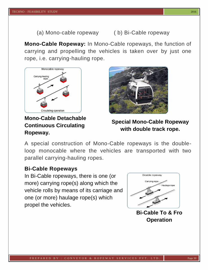
(a) Mono-cable ropeway ( b) Bi-Cable ropeway
Mono-Cable Ropeway: In Mono-Cable ropeways, the function of
carrying and propelling the vehicles is taken over by just one
rope, i.e. carrying-hauling rope.
Mono-Cable Detachable
Continuous Circulating
Ropeway.
Special Mono-Cable Ropeway
with double track rope.
A special construction of Mono-Cable ropeways is the double-
loop monocable where the vehicles are transported with two
parallel carrying-hauling ropes.
Bi-Cable Ropeways
In Bi-Cable ropeways, there is one (or
more) carrying rope(s) along which the
vehicle rolls by means of its carriage and
one (or more) haulage rope(s) which
propel the vehicles.
Bi-Cable To & Fro
Operation

TECHNO – FEASIBILITY STUDY 2016
P R E P A R E D B Y : C O N V E Y O R & R O P E W A Y S E R V I C E S P V T . L T D . Page 31
Classification depending upon type of Movement
Under this category of classification, ropeway system can be
classified as-
a. To & Fro Motion.
b. Circulating operation
c. Pulsating Ropeways
To & Fro Motion (Jig-Back) : In this type of ropeways, the
vehicle oscillates “To & Fro” between stations on the same track
by inverting the hauling ropes direction of motion.
Circulating Operation: In circulating operation ropeways, the
vehicles are propelled by constant intermittent running ropes. Up
& Down transportation takes place in different tracks. The
circulating ropeways can be further subdivided into-
1 Fixed Grip Installations:
Where the carriers are permanently attached to the haulage or
Carrying-hauling rope is called Fixed Grip type ropeway.
2 Detachable installations : In case of detachable ropeways,
the grip of carriers are detached and re-attached in the stations.
Pulsating Ropeways :
Schematic of Pulsating Ropeway

TECHNO – FEASIBILITY STUDY 2016
P R E P A R E D B Y : C O N V E Y O R & R O P E W A Y S E R V I C E S P V T . L T D . Page 32
This type of ropeway the speed of the rope can be varied. It can
go up to a definite speed but when the vehicles approach
station, vehicle speed is reduced and finally it comes to a halt .
This is generally used for transportation of passengers in
amusement parks. During de-boarding and boarding, all other
vehicles are stationery in line.
However, for the purpose of material transportation, the following
types of Ropeway System are in use :
a. Continuously Moving Mono-Cable Ropeway with Fixed Grip
b. Continuously Moving Mono-Cable Ropeway with
Detachable Grip
c. Continuously Moving Bi-Cable Ropeway with Detachable
Grip
d. Double track Bicable System
A brief operational features of each system and its advantages /
disadvantages are given below:-
a. Continuously Moving Mono-Cable Ropeway with
Conventional Grip.
In this system a single endless
rope supported on intermediate
tower sheaves serves the dual
purpose of carrying as well as
hauling a carrier suspended on it
from one place to the other. The
carriers are suspended from the CONVENTIONAL MONOCABLE SYSTEM

TECHNO – FEASIBILITY STUDY 2016
P R E P A R E D B Y : C O N V E Y O R & R O P E W A Y S E R V I C E S P V T . L T D . Page 33
rope and clipped to it by the gravity force arising out of its own
weight as also weight of material. When driven, the carrier
moves with the rope from one point to the other. At the stations
the carriers are automatically detached from the moving rope to
facilitate loading / unloading operation.
Advantages Low capital investment.
Simple in construction, operation and
maintenance.
Skilled operative personnel are not required.
Limited number of equipments / moving
parts. Hence low operation cost.
Disadvantages
Limited transport capacity. High rate of
transportation is not possible.
Cannot negotiate steep gradient. Since the
carriers are clipped to the rope by gravity
force only, possibility of slippages while
negotiating a gradient is high. Hence
generally unsuitable for a hilly terrain.
Large span between supports are not
possible. Hence capability of negotiating a
gorge / valley is limited.
Maintenance of large number of towers and
tower mechanicals.
High speed is not possible.

TECHNO – FEASIBILITY STUDY 2016
P R E P A R E D B Y : C O N V E Y O R & R O P E W A Y S E R V I C E S P V T . L T D . Page 34
b. Continuously Moving Mono-Cable Ropeway with
Detachable Grip :
This system is a development in
a material Ropeway system.
Operating principal is same as
conventional monocable. Only
difference is that a special grip
with the carriers are used which
remain firmly attached by some
external forces provided through
a pair of special spring in
DETACHABLE GRIP TYPE MONOCABLE
SYSTEM
addition to gravity forces. when the carrier approaches or
leaves a station, it passes over a special device where the
grip automatically detaches itself from the continuously
moving rope and moves on fixed structure and the chair /
cabin speed is reduced. At the time of leaving the station,
the carrier catches n to the continuously moving rope and
while passing though a device installed at the stations, the grip
are automatically coupled to the moving rope. This type of
ropeway can go up to a speed of 6 mps (however, in India
the maximum permissible speed is 4 mps).
Advantages Can negotiate steep gradient.
Can follow the natural ground terrain
eliminating the need of tall towers while
negotiating a gorge / valley. Hence ideally
suitable for a hilly terrain.
Low capital expenses compared to Bicable

TECHNO – FEASIBILITY STUDY 2016
P R E P A R E D B Y : C O N V E Y O R & R O P E W A Y S E R V I C E S P V T . L T D . Page 35
system.
Simple in construction, operation and
maintenance.
Disadvantages Cannot have high transport capacity.
Installation and operation costs are higher
than conventional system.
Large span between towers not possible.
Hence maintenance of many towers and
tower mechanicals.
High speed not possible.
c. Continuously Moving Bi-Cable Ropeway with
Detachable Grip :
In bicable system, there is tensioned stationery Track Ropes both on Load and empty side and a second endless rope attached to each carrier. The carriers are suspended from the Track Ropes at intervals which carry their weight. The Haul Rope is firmly attached to the carrier
and when driven, move the carriers BICABLE SYSTEM
from one point to the other. The Bicable system, because of special locked coil type Track Ropes and more complicated carriages are always more expensive than a Monocable System.
This type of ropeway can go up to a speed of 10 mps on track rope and 7.5 mps over line supports i,e; saddles on line trestles as when the cabin reaches station, it detaches itself from the

TECHNO – FEASIBILITY STUDY 2016
P R E P A R E D B Y : C O N V E Y O R & R O P E W A Y S E R V I C E S P V T . L T D . Page 36
continuously moving hauling rope and moves on fixed structure and the cabin speed is reduced to crawling speed. This type is very costly and requires maximum mechanicals in stations. With this type system longer unsupported span is possible.
Advantages
Large Single span possible.
High transport capacity and speed.
Less number of moving parts.
Disadvantages High capital investment.
System being sophisticated requires
qualified Operational & Maintenance Staff.
d. Double Track Bicable System
In double track bicable system, there is tensioned stationery 2
(two) Track Ropes both on Load and empty side and a second
endless rope attached to each carrier. The carriers are
suspended from the Track Ropes at intervals which carry their
weight. The Haul Rope is firmly attached to the carrier and when
driven, move the carriers from one point to the other. The
Double Track Bicable System, because of numbers of special
locked coil type Track Ropes and more complicated carriages
are always more expensive than a Monocable and a Bicable
System.

TECHNO – FEASIBILITY STUDY 2016
P R E P A R E D B Y : C O N V E Y O R & R O P E W A Y S E R V I C E S P V T . L T D . Page 37
Advantages
Large Single span possible.
Very high transport capacity and speed.
Less number of moving parts.
Disadvantages
High capital investment.
System being sophisticated requires
qualified O & M Staff
**********************
1 - Twin Track Rope
FIg. -1
Schematic view of DoubleTrack System
2 - Haulage Rope 3 - Tension wt. for Track Ropes 4 - Tension wt. for Haulage Rope
5 - Track Rope Anchorage 6 - Drive 7 - Shunt Rail 9 - Bucket & Carriage8 - Trestle

TECHNO – FEASIBILITY STUDY 2016
P R E P A R E D B Y : C O N V E Y O R & R O P E W A Y S E R V I C E S P V T . L T D . Page 38
CHAPTER – IV
RECOMMENDED ROPEWAY SYSTEM
Based on the capacity requirements of materials to be transported
and other environmental factors like the terrain & topographical
profile along the alignment, length of the ropeway to be installed,
acceptable rope gradient (angle of uphill ascends & downhill
descends) as per norms, layout & span between the stations as per
specifications of Indian Standards, geology of the area, remoteness
of area, dense forest coverage, it has been technically evaluated
that following Ropeway systems would be the best possible
economical design of ropeway meeting all the requirements of
HPPCL.
Detail of Ropeways for Chanju – III HEP (48 MW)
Sl No.
Description Type of Ropeway System
Load carrying capacity
1. Ropeway – 1 (R1)
Twin track Bi Cable – Jigback
3 MT
2. Ropeway – 2 (R2) 3 MT
3. Ropeway – 3 (R3) 3 MT
4. Ropeway – 4 (R4) 3 MT
5. Ropeway – 5 (R5) 3 MT
6. Ropeway – 6 (R6) 6 MT

TECHNO – FEASIBILITY STUDY 2016
P R E P A R E D B Y : C O N V E Y O R & R O P E W A Y S E R V I C E S P V T . L T D . Page 39
The objective of HPPCL is to use the ropeway is for
transportation of Construction materials from road side to the
work Site on the other side of the loading station over the river.
The straight path encountered most hostile terrain with steep
gradient with deep and wide gorges and valleys and much more
inaccessible.
Revised Load
Sl No.
Description Type of Ropeway System
Load carrying capacity
1. Ropeway – 1 (R1) Bi Cable - Jig Back
2.0 MT
2. Ropeway – 2 (R2) 2.0 MT
3. Ropeway – 3 (R3) 2.0 MT
4. Ropeway – 4 (R4) 2.0 MT
5. Ropeway – 5 (R5) 2.0 MT
6. Ropeway – 6 (R6) Twin track Bi Cable – Jigback 3.5 MT
a. Depending on the operating capacity requirement, the
recommended Ropeways can be conveniently achieve
b. Ropeway System can easily and conveniently negotiate the
terrain, the steep gradient and long span across deep valleys &
gorges,
c. The mechanical components involved in the installation is not
much, therefore, it is easy to operation and maintain.
d. The system does not demand highly skilled or experienced
work force to operate and maintenance since human capacity is
a challenge in the region.

TECHNO – FEASIBILITY STUDY 2016
P R E P A R E D B Y : C O N V E Y O R & R O P E W A Y S E R V I C E S P V T . L T D . Page 40
The following table showing the Ropeway station locations:-
Ropeways for Chanju – III HEP (48 MW)
Station Location
Co-ordinates Elevation (RL) (M)
Distance (M) between stn
Northing (M) (Latitude)
Easting (M) (Longitude)
R1 Loading
Chanju 3619768.088 623741.293 2244.015
741.174 Unloading 3619032.461 623831.801 2100.000
R2 Loading
Chanju 3619682.957 623435.602 2248.531
899.552 Unloading 3618796.986 623279.879 2082.939
R3 Loading
Chanju 3619761.874 623013.548 2252.672
851.738 Unloading 3618964.278 622714.721 2084.827
R4 Loading
Chanju 3620179.169 621990.491 2122.784
897.544 Unloading 3619297.818 621820.767 2086.467
R5 Loading
Chanju 3620387.416 621455.380 2035.487
1117.221 Unloading 3619836.843 620505.513 2061.104
R6 Loading
Chanju 3620861.945 619398.679 1885.514
947.875 Unloading 3619914.225 619415.830 2088.678
SYSTEM CONCEPT
A. Ropeways for Chanju – III HEP (48 MW)
Considering the requirement of the various parameters for the
ropeway and its suitability to the operation and the ground profile it is
proposed for a Twin Track Bi Cable ropeway system. The following
points are to be kept in mind while designing this ropeway.
1. The ropeway shall be suitable for carrying construction
materials e.g. cement, astragals, sand, reinforcement bar,
components, and concrete mixing machine in dismantled
condition.
Rev. 1

TECHNO – FEASIBILITY STUDY 2016
P R E P A R E D B Y : C O N V E Y O R & R O P E W A Y S E R V I C E S P V T . L T D . Page 41
As per mail dated 06.02.2016 the following material loads to be
considered for the ropeway near the power house of the project.
Chanju III HEP.
i) Approx weight of Butterfly valve – 6 MT.
ii) Approx. weight of penstock one shell – 4 MT.
However the maximum weight of material to be transported
through other ropeways shall be remained unchanged.
2. Material to be loaded and unloaded at the terminal stations
only.
3. The ropeway will be driven by electric motor through suitable
control drive system.
4. Minimum no. of rope supporting trestle to be considered. Since
the ropeway profile for almost all cases are crossing Nallah or
small stream it is preferred to avoid trestle in between.
5. Since the ropeway profile is across a Nallah or stream there is
possibility of high wind velocity.
SYSTEM WORKING DESCRIPTION
It is proposed to be a twin track bi-cable jig back ropeway with single
hauling rope. There shall be two nos. track rope running from
Loading Station to Unloading station. There could be one or two
trestle to support the track rope. However, for almost all the
ropeways there will be no intermediate trestle. Both track ropes will

TECHNO – FEASIBILITY STUDY 2016
P R E P A R E D B Y : C O N V E Y O R & R O P E W A Y S E R V I C E S P V T . L T D . Page 42
be anchored positively to anchor bracket/ frame on foundation. The
track ropes will pass over the saddles mounted on station structure.
To the Lower station the rope is anchored through mechanical
tensioning device and then to anchor bracket on the foundation. The
track ropes are tensioned for the recommended tension and done in
such a way that they are parallel throughout.
An endless hauling rope runs all along the center of the track ropes
and below it. The hauling rope is clamped to the carriage to give the
required motion. Hauling rope is given the required tensions by
weighted type gravity tension in tension tower.
Ropeway main drive comprises of main electric AC motor with VVVF
drive and a helical gearbox coupled to the drive sheave shaft. There
are two nos. of brake provided in the drive. One on the gearbox input
shaft and the other is on the drive sheave.
The electric motor drive is controlled by VVVF drive that adjusts the
demand of power and maintains a constant speed. For a condition
when the system is regenerative the drive dissipates the energy
through thermal dissipater and maintains the constant speed.
Acceleration and deceleration of the ropeway is to be controlled by
the electric drive system.
The ropeway drive mechanicals comprises of suitable diameter drive
sheave made out of good quality cast iron / cast steel / steel
fabrication as per design requirement. The drive sheave rope groove
shall have suitable machined groove with or with out liner as per
design and life requirement. A lined groove will give longer life to

TECHNO – FEASIBILITY STUDY 2016
P R E P A R E D B Y : C O N V E Y O R & R O P E W A Y S E R V I C E S P V T . L T D . Page 43
rope and drive. This sheave is mounted on machined steel shaft and
supported in antifriction bearing housing. The end of shaft will be
fitted with geared coupling and is then coupled to a rugged helical
gearbox of size to suit the drive requirement.
Suitable size AC squirrel cage induction motor is coupled to the input
shaft of the gearbox through flexible / resilient type coupling with a
provision of brake drum for external braking by thrustor brake.
Additional disc brake of suitable size and capacity to be fitted to the
other side of drive sheave shaft. This will act as emergency / parking
brake.
Deflection sheaves are used to guide the rope from drive or return
sheave to the line sheave at station front.
Note : Incase of Bicable Jig back System in place of two Track Ropes only one track rope will be there, rest will remain same as above.
Based on the meeting held on 08.04.16, at the O/o General Manager (Designs), Sundernagar and the letter No. HPPCL/DGM/RCP/G-6/2016-78-81 dt. 16.04.16., the modified loads are as follows:- a) Chanju III HEP Ropeway R1,R2,R3,R4 & R5 – Max. Payload 2 MT Ropeway R6 – Max. Payload 3.5 MT b) Deothal Chanju HEP (Alternative – I)
i) Cross Ropeways Ropeway DR1, DR2, DR3, & DR4 – Max. Payload 2 MT Ropeway DR5 – Max. Payload 3 MT ii)Longitudinal Ropeways Ropeway Section I to Section V – Max. Payload 2 MT Ropeway Section VI – Max. Payload 3 MT

TECHNO – FEASIBILITY STUDY 2016
P R E P A R E D B Y : C O N V E Y O R & R O P E W A Y S E R V I C E S P V T . L T D . Page 44
Accordingly, CRSPL had reworked out the above specified loads on the aforesaid Ropeway alignments and based on the Load work out, it is felt that Best Suited Systems are as follows:- Detail of Ropeways for Chanju – III HEP (48 MW)
Sl No.
Description Type of Ropeway System
1. Ropeway – 1 (R1) Bi cable Jig Back
2. Ropeway – 2 (R2) Bi cable Jig Back
3. Ropeway – 3 (R3) Bi cable Jig Back
4. Ropeway – 4 (R4) Bi cable Jig Back
5. Ropeway – 5 (R5) Bi cable Jig Back
6. Ropeway – 6 (R6) Twin track Bi cable Jig Back
SYSTEM WORKING DESCRIPTION for Unloading Stations
The Unloading Station is an elevated / ground structure. The
operation of the station is as follows:
A loaded trolley on arriving at the station entrance to be stopped for
unloading of material. The ropeway stops automatically at a pre
determined position in the station. Check that the brake is engaged
before working in the trolley for unloading. By the help of the lifting
mechanism provided in the carriage assembly lower the trolley on
the station floor. Anchor the trolley by suitable chain and hook so that
the trolley does not move while the unloading is being done. Now
bring the Hydra or other Lifting machine to suit the load. In case the
materials can be manually unloaded the same can be done.

TECHNO – FEASIBILITY STUDY 2016
P R E P A R E D B Y : C O N V E Y O R & R O P E W A Y S E R V I C E S P V T . L T D . Page 45
After unloading clean the trolley and then load with materials that is
planned to be lowered to lower station, if any.
Two nos. manual Chain pulley blocks of suitable capacity are fitted to
the bottom hooking points on either side of the carriage. The trolley
to be raised by means of the lifting device in the carriage so that it
clears the floor while making the return journey. It is necessary to
align and level the trolley by suitable adjustment and the hoist to be
locked.
At the return station there is a return sheave same as drive sheave
mounted on tension trolley. This tension trolley moves on rail to
provide the to and fro motion for the tensioning of the haulage rope.
To other side of the tension trolley the tension rope is attached and it
passes over the sheaves on tension tower and connected to counter
weight. Adequate rope tension is provided by this gravity type
tensioning arrangement.
The track rope is tensioned by means of tension screw. This system
is required to align the two track ropes for similar catenery.

TECHNO – FEASIBILITY STUDY 2016
P R E P A R E D B Y : C O N V E Y O R & R O P E W A Y S E R V I C E S P V T . L T D . Page 46
SCHEMATIC DIAGRAM OF UNLOADING STATION

TECHNO – FEASIBILITY STUDY 2016
P R E P A R E D B Y : C O N V E Y O R & R O P E W A Y S E R V I C E S P V T . L T D . Page 47
SYSTEM WORKING DESCRIPTION for Loading Station
The Loading Station is a ground level structure. The operation of this
station will be as follows:
An empty Trolley approaching the station will be automatically
slowed down by the VVVF controlled drive and will stop at a
predetermined location. Now, if this is an empty trolley material can
be loaded with care. The trolley to be anchored after it is lowered to
the station. load the materials and place them properly so that the
loading is uniform and does not make eccentric loading. Tie tem
properly with the trolley frame by manila rope.
Raise the trolley to about 450 mm above the station floor so that
it does foul with the floor. Lock the lifting device properly. Check
the center of gravity is balanced so that the trolley is horizontal.
Before starting the ropeway Clear anchor and any other
obstruction in the way of trolley movement.
Ropeway drive will be located at Upper Station. The main motor,
gearbox, other transmission machinery including control panel
will be located here. The main drive will have option to drive from
power from D G set.
The ropeway will operate in forward direction to lift material to
upper station. When operating in reverse direction it will lower
the trolley to lower station.
The haulage rope will be made endless by splicing and will
return from the return station. The rope tension will be provided
at lower station. Haulage rope will have weighted tension

TECHNO – FEASIBILITY STUDY 2016
P R E P A R E D B Y : C O N V E Y O R & R O P E W A Y S E R V I C E S P V T . L T D . Page 48
whereas the track rope will have fixed tension by screw
mechanism. Since the land between the Lower station and Upper
station is a very rough terrain intermediate trestle has been
avoided as far as possible.
SCHEMATIC DIAGRAM OF LOADING STATION

TECHNO – FEASIBILITY STUDY 2016
P R E P A R E D B Y : C O N V E Y O R & R O P E W A Y S E R V I C E S P V T . L T D . Page 49
SAFETY:
The electric control system will stop the trolley at a
predetermined position in the station. In the event of any
further forward movement the safety limit switch will trip the
system and will not allow further beyond the safe limit.
There will be a set of rope catcher for the haulage to
prevent it from going out of the sheaves.
Electrical safety system will be provided in the panel as per
standard practice.
There will be a telecommunication system by telephone
between the Lower and Upper station.
The ropeway should not be operated when the wind speed
exceeds 30 KMPH.
During the period when ropeway is not operating the trolley
must be brought at station and lowered to the floor and
anchored.
The objectives and advantages offered by Aerial Ropeway
The main objective of installation of the proposed ropeway, as mentioned earlier, is to transport construction material.
Looking at various options of transport system, there are only two options available either road transport or aerial ropeway system, in which ropeway installation is fast, eco friendly as well as economic.

TECHNO – FEASIBILITY STUDY 2016
P R E P A R E D B Y : C O N V E Y O R & R O P E W A Y S E R V I C E S P V T . L T D . Page 50
Ropeway System can negotiate steep gradient, with less space.
Ropeway is an environment friendly system. There will be very less impact of the ecology and environment during the installation and operation of ropeway system. There will not be stress on the forest and its coverage can be maintained intact during the operation.
Ropeway, generally, does not change the land use pattern.
It rarely requires displacement or relocation. Being aerial, it does not obstruct the movement underneath.
There will not be any conflict on the wild life as the operation of ropeway does not generate any vibrations, sound, heat, etc. that might have negative impact on the wild life.
As ropeway is electrically operated, there will not be additional pressure on the requirement of fossil fuel for transportation of materials.
Ropeway can save the surrounding greeneries from the fumes of the vehicles arising from road transport. Regular vehicular movement along the hill road may destroy the natural beauty and habitations and will increase the cost of maintenance of the roads.
Ropeway System will minimize the transportation cost substantially and there will be no problem as related to the road transportation. Reliability of transportation of material is much more, incase of Ropeway at the Hilly area / road.
Since Ropeway will directly transfer the material, it will reduce the contamination and wastage of the material.
******************

TECHNO – FEASIBILITY STUDY 2016
P R E P A R E D B Y : C O N V E Y O R & R O P E W A Y S E R V I C E S P V T . L T D . Page 51
CHAPTER – V
DESIGN OF THE ROPEWAY SYSTEM DESIGN PARAMETERS AND SPECIFICATIONS
Working Data Ropeways for Chanju – III HEP (48 MW) R1 R2 R3 R4 R5 R6
a. Type of Ropeway : Twin Track Bi Cable Jig Back
b. No. of Drive Station : 1 1 1 1 1 1
c. No. of Stations : 2 2 2 2 2 2
d. Operation : 8 hrs/ day
e. Material to be transported
: CONSTRUCTION MATERIAL, MACHINERY & BUTTERFLY
VALVE, PENSTOCK
f. No. of sections : 1 1 1 1 1 1
g. Horizontal Length (M) (approx)
: 741.174 899.592 851.738 897.544 1117.221 947.875
h. Difference in Level between stations (M) (approx)
: 144.015 165.592 167.845 36.317 25.617 203.161
i. Transport Capacity : 3T 3T 3T 3T 3T 6 T
j. Bucket Payload (T) : 3T 3T 3T 3T 3T 6 T
k. Line Speed (M/ Sec) : 2.0
l. Trolley travel time (Min) approx.
: 6.5 7.5 7.5 7.5 10 8
m. Track Rope Size (MM)
: 34 34 34 34 38 38
n. Haulage Rope Size (MM)
: 22 22 22 22 22 25
o. Motor rating (KW) : 90 KW 55 KW 132 KW
p. Total Number of Buckets
: 1 1 1 1 1 1
q. Gauge of the Line (M)
: - - - - - -
r. Number to Towers / TRD
: NIL
s. Tower Construction : NIL

TECHNO – FEASIBILITY STUDY 2016
P R E P A R E D B Y : C O N V E Y O R & R O P E W A Y S E R V I C E S P V T . L T D . Page 52
REVISED LOADS
R1 R2 R3 R4 R5 R6
a. Type of Ropeway : Bi Cable Jig Back Twin Track Bi Cable Jig
Back
b. No. of Drive Station : 1 1 1 1 1 1
c. No. of Stations : 2 2 2 2 2 2
d. Operation : 8 hrs/ day
e. Material to be transported
: CONSTRUCTION MATERIAL, MACHINERY & BUTTERFLY
VALVE, PENSTOCK
f. No. of sections : 1 1 1 1 1 1
g. Horizontal Length (M) (approx)
: 741.174 899.592 851.738 897.544 1117.221 947.875
h. Difference in Level between stations (M) (approx)
: 144.015 165.592 167.845 36.317 25.617 203.161
i. Transport Capacity : 2T 2T 2T 2T 2T 3.5 T
j. Bucket Payload (T) : 2T 2T 2T 2T 2T 3.5 T
k. Line Speed (M/ Sec) : 2.0
l. Trolley travel time (Min) approx.
: 6.5 7.5 7.5 7.5 10 8
m. Track Rope Size (MM)
: 32 32 32 32 32 38
n. Haulage Rope Size (MM)
: 19 19 19 19 19 25
o. Motor rating (KW) : 50 37 90
p. Total Number of Buckets
: 1 1 1 1 1 1
q. Gauge of the Line (M)
: - - - - - -
r. Number to Towers / TRD
: NIL
s. Tower Construction : NIL
TECHNO – FEASIBILITY STUDY 2016
P R E P A R E D B Y : C O N V E Y O R & R O P E W A Y S E R V I C E S P V T . L T D . Page 53
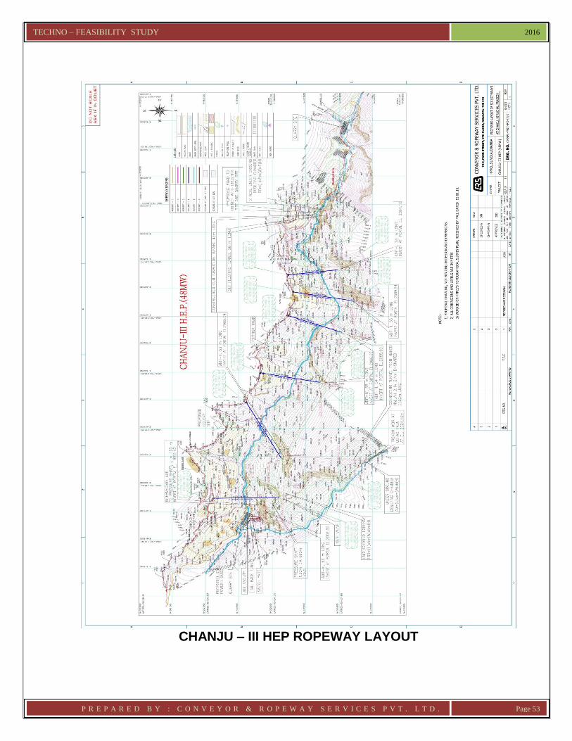
CHANJU – III HEP ROPEWAY LAYOUT

TECHNO – FEASIBILITY STUDY 2016
P R E P A R E D B Y : C O N V E Y O R & R O P E W A Y S E R V I C E S P V T . L T D . Page 54
CHANJU – III HEP ROPEWAY 1 (R1) ALIGNMENT

TECHNO – FEASIBILITY STUDY 2016
P R E P A R E D B Y : C O N V E Y O R & R O P E W A Y S E R V I C E S P V T . L T D . Page 55
CHANJU – III HEP ROPEWAY 2 (R2) ALIGNMENT

TECHNO – FEASIBILITY STUDY 2016
P R E P A R E D B Y : C O N V E Y O R & R O P E W A Y S E R V I C E S P V T . L T D . Page 56
CHANJU – III HEP ROPEWAY 3 (R3) ALIGNMENT

TECHNO – FEASIBILITY STUDY 2016
P R E P A R E D B Y : C O N V E Y O R & R O P E W A Y S E R V I C E S P V T . L T D . Page 57
CHANJU – III HEP ROPEWAY 4 (R4) ALIGNMENT

TECHNO – FEASIBILITY STUDY 2016
P R E P A R E D B Y : C O N V E Y O R & R O P E W A Y S E R V I C E S P V T . L T D . Page 58
CHANJU – III HEP ROPEWAY 5 (R5) ALIGNMENT

TECHNO – FEASIBILITY STUDY 2016
P R E P A R E D B Y : C O N V E Y O R & R O P E W A Y S E R V I C E S P V T . L T D . Page 59
CHANJU – III HEP ROPEWAY 6 (R6) ALIGNMENT

TECHNO – FEASIBILITY STUDY 2016
P R E P A R E D B Y : C O N V E Y O R & R O P E W A Y S E R V I C E S P V T . L T D . Page 60
CHAPTER - VI
PLANT MACHINERY FOR THE PROPOSED ROPEWAY SYSTEM
The main plant machinery of the ropeway system comprises of following:
01. Main Driving Mechanism comprising of Drive Sheave, Open Gear and Pinion, worm or helical gear, shafting, couplings, service and emergency brakes.
02. Wire Rope.
03. Wire rope support towers if required.
04. Rope Tensioning Arrangement comprising of Sheaves and Tension Tower, Turn buckle etc.
05. Station Mechanicals comprising of Rope Guide / deflection sheaves, Bucket / trolley guide, etc.
06. Line mechanicals comprising of Line Sheaves, Articulated Sheave Mounts, supporting pedestal / Bracket, Rope Catcher etc. as required.
07. Buckets/ Trolleys complete with carriage and hanger.
08. Power supply and electrical system comprising of AC motors, frequency controller, MCC, Switches, Power and Control Cables.
09. Safety devices as described in later Chapter.
10. Telecommunication and signaling items comprising of telephones, wires, siren / hooter, glow lamp, etc.
11. Diesel generator sets for emergency power supply

TECHNO – FEASIBILITY STUDY 2016
P R E P A R E D B Y : C O N V E Y O R & R O P E W A Y S E R V I C E S P V T . L T D . Page 61
Plant and Equipment Specification
a. Rope : Track Rope : Locked coil track rope for aerial ropeway, 1570 N/sq. mm tensile grade. Haulage Rope : 6 x 19 Seale construction, RHL, made from bright wires, 1770 N / sq. mm Tensile grade.
b. Carrier : Bucket / Trolley : The Ropeway Bucket shall be made of Steel Sheets and sections welded. A typical Bucket has been shown in the enclosed drawing. Design of the Bucket / Trolley shall be such that these can be raised or lowered at station for easy loading and unloading. The trolley will be suspended from the carriage and hanger assembly. Carriage : Carriage fitted with hauling Rope gripping device. The gripping force exerted on the rope should be adequate to withstand with sufficient factor of safety, the maximum slipping force that will be induced on the grip while negotiating the worst gradient. The carriage is supported on articulated wheel assembly that runs on track rope.
c. Intermediate Tower and Tower Mechanicals (If required) Trestle : Towers of rolled steel sections and in latticed construction. All members of the towers shall preferably be welded as far as practicable from the transportation and erection point of view. Trestle Roller : Trestle Roller shall be made of best cast iron

TECHNO – FEASIBILITY STUDY 2016
P R E P A R E D B Y : C O N V E Y O R & R O P E W A Y S E R V I C E S P V T . L T D . Page 62
having sufficient diameter to support the haulage rope. Each will be fitted with adequate sized ball bearing halves mountings and carbon steel spindle.
d. STATION EQUIPMENT Ropeway Driving Gears : Driving units for traction ropes of modern design and construction, shall comprise, interalia, the following:
Special enclosed reduction gears with machine cut teeth and steel shafting, running in heavy ball or roller bearing.
Mechanical brake for parking purposes applied manually.
Steel shafting mounting in heavy ball or roller bearing.
Spur rings of special construction bolted to the driving sheaves and meshing with spur pinions.
Disc brake with operating mechanism applied automatically.
Heavy Driving Sheave of best closed grained cast iron construction with special tread. The sheave may be of fabricated construction also.
Idler sheaves
Slow speed operating devices.
Tension Gears for the Traction Rope : Tension gear for automatically tensioning the haulage Rope, each comprising of ball or roller bearing mounted sheave, trolley on rollers, tension race, winch for rope adjustment, tension rope, axles and mild steel cages for tension weights. Traction Rope Guide Sheaves : Cast Steel rollers and cast iron sheaves of large diameter, as required for deflection or support of the haulage rope in stations, each provided with carbon steel spindle and suitable bearing mountings.

TECHNO – FEASIBILITY STUDY 2016
P R E P A R E D B Y : C O N V E Y O R & R O P E W A Y S E R V I C E S P V T . L T D . Page 63
Station Rail : Running rail at the station shall be fabricated out of IS:2062 sections and plates. The bends / curves in vertical and / or horizontal planes shall be smooth and free of kinks, protrusions etc. the horizontal return curve at the rear of the station shall have sufficient radius in conformity with the carriage design to effect smooth passage of the cars around bends. Oiling Apparatus for Haulage Ropes : The apparatus for lubricating the haulage rope shall comprise of oil tank with adjustable feed and wire brushes. The apparatus shall be dip feed type. Steel Work : Station steel work fabricated out of rolled steel sections and plates, bolted or welded. The stations to be housed in steel building of adequate size and shape so as to have sufficient clear space for movement of operating personnel.
e. Gear-box, Gear Coupling & Pin Bush Coupling Gear Box : Gear Box mechanical ratings should not be less than 1.25 times of the rating of its drive motor or as per manufacturer’s selection method whichever is higher. Type of conveyor drive gear boxes should be as mentioned in data sheet. Gear Coupling : Couplings shall be able to absorb parallel and angular misalignment. These shall have crowned external teeth of the hub which shall engage with the straight internal teeth of the sleeve. The pressure angle, the amount of crowning and back-lash values shall be chosen with a view to achieve the best result in the load carrying capacity.

TECHNO – FEASIBILITY STUDY 2016
P R E P A R E D B Y : C O N V E Y O R & R O P E W A Y S E R V I C E S P V T . L T D . Page 64
Pin Bush Coupling : the pin-bush couplings shall consist of two cast iron/steel flanges fitted with high tensile bolts and rubber bushes. Couplings shall be capable of being disconnected easily by withdrawal of pin. Couplings shall be able to absorb shock, variation and misalignment.
f. Track Rope Divide Stations These are intermediate stations to provide Tension / Anchorage to the Track Ropes. In long Industrial Ropeways, it is often necessary to reduce single length of track Ropes to facilitate transportation and erection and also to reduce frictional resistance and thereby allowing free movement of the Tension Weight. Stations are either Double Anchorage or Double Tension or Tension cum Anchorage type. Rope tensions are provided by means of suspended weight while Anchorage by socketings / clamping devices. These are elevated structures. The buckets pass through these stations automatically without stopping or being detached from the hauling rope. The Track Ropes entering and leaving the stations rest on deflection saddles and are deflected towards the Ropeway centre line to clear the buckets moving along the station rails.

TECHNO – FEASIBILITY STUDY 2016
P R E P A R E D B Y : C O N V E Y O R & R O P E W A Y S E R V I C E S P V T . L T D . Page 65
Typical Track Rope Divide Station

TECHNO – FEASIBILITY STUDY 2016
P R E P A R E D B Y : C O N V E Y O R & R O P E W A Y S E R V I C E S P V T . L T D . Page 66
SCHEMATIC ARRANGEMENT OF MATERIAL TROLLEY AND
CARRIAGE

TECHNO – FEASIBILITY STUDY 2016
P R E P A R E D B Y : C O N V E Y O R & R O P E W A Y S E R V I C E S P V T . L T D . Page 67
SCHEMATIC ARRANGEMENT OF CARRIAGE

TECHNO – FEASIBILITY STUDY 2016
P R E P A R E D B Y : C O N V E Y O R & R O P E W A Y S E R V I C E S P V T . L T D . Page 68
Typical Track Rope Anchorage

TECHNO – FEASIBILITY STUDY 2016
P R E P A R E D B Y : C O N V E Y O R & R O P E W A Y S E R V I C E S P V T . L T D . Page 69
Typical Drive Arrangement

TECHNO – FEASIBILITY STUDY 2016
P R E P A R E D B Y : C O N V E Y O R & R O P E W A Y S E R V I C E S P V T . L T D . Page 70
Typical Deflection Sheave Arrangement

TECHNO – FEASIBILITY STUDY 2016
P R E P A R E D B Y : C O N V E Y O R & R O P E W A Y S E R V I C E S P V T . L T D . Page 71
Typical Bucket

TECHNO – FEASIBILITY STUDY 2016
P R E P A R E D B Y : C O N V E Y O R & R O P E W A Y S E R V I C E S P V T . L T D . Page 72
Bucket Carrying Material

TECHNO – FEASIBILITY STUDY 2016
P R E P A R E D B Y : C O N V E Y O R & R O P E W A Y S E R V I C E S P V T . L T D . Page 73
Typical Trestle Arrangement

TECHNO – FEASIBILITY STUDY 2016
P R E P A R E D B Y : C O N V E Y O R & R O P E W A Y S E R V I C E S P V T . L T D . Page 74
Typical Track Rope Anchorage ********************

TECHNO – FEASIBILITY STUDY 2016
P R E P A R E D B Y : C O N V E Y O R & R O P E W A Y S E R V I C E S P V T . L T D . Page 75
DESIGN CALCULATIONS
ROPEWAYS AT CHANJU III 48 MW
CHANJU III 48 MW Ropeway No. R1
ITEM UNIT VALUE
Horizontal Length M 741.174
Level difference M 144.015
Inclined length (Approx) M 755.04
Slope Deg 11.00
Wt of carriage and trolley (Estimated) Kg 1800
Load (Materials) Kg 3000
Haulage rope Dia. mm 22
Wt. Rate Kg/m 1.98
Applied Tension Te 4.5
H rope MBL (1960 N/mm2 grade) kN 314
F O S Haulage rope 4.78
Track rope Dia. mm 34
Tr Rope wt rate Kg/m 6.48
MBL (1570 N/mm2 grade) kN 1100
Track rope appl. Tension Te 29.5
F O S Track rope 3.8
CLIMB ANGLE Deg 21.03
Total pull Kg 2200.251
Speed m/s 2
KW required KW 43.154
Drive efficiency % 75
Motor required KW 71.924
Provide Motor KW 90
Travel time sec 484
TECHNO – FEASIBILITY STUDY 2016
P R E P A R E D B Y : C O N V E Y O R & R O P E W A Y S E R V I C E S P V T . L T D . Page 76
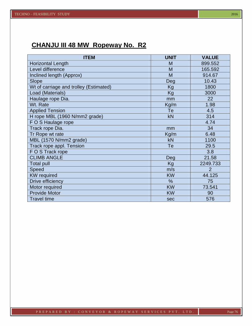
CHANJU III 48 MW Ropeway No. R2
ITEM UNIT VALUE
Horizontal Length M 899.552
Level difference M 165.592
Inclined length (Approx) M 914.67
Slope Deg 10.43
Wt of carriage and trolley (Estimated) Kg 1800
Load (Materials) Kg 3000
Haulage rope Dia. mm 22
Wt. Rate Kg/m 1.98
Applied Tension Te 4.5
H rope MBL (1960 N/mm2 grade) kN 314
F O S Haulage rope 4.74
Track rope Dia. mm 34
Tr Rope wt rate Kg/m 6.48
MBL (1570 N/mm2 grade) kN 1100
Track rope appl. Tension Te 29.5
F O S Track rope 3.8
CLIMB ANGLE Deg 21.58
Total pull Kg 2249.733
Speed m/s 2
KW required KW 44.125
Drive efficiency % 75
Motor required KW 73.541
Provide Motor KW 90
Travel time sec 576

TECHNO – FEASIBILITY STUDY 2016
P R E P A R E D B Y : C O N V E Y O R & R O P E W A Y S E R V I C E S P V T . L T D . Page 77
CHANJU III 48 MW Ropeway No. R3
ITEM UNIT VALUE
Horizontal Length M 851.738
Level difference M 167.845
Inclined length (Approx) M 868.12
Slope Deg 11.15
Wt of carriage and trolley (Estimated) Kg 1800
Load (Materials) Kg 3000
Haulage rope Dia. mm 22
Wt. Rate Kg/m 1.98
Applied Tension Te 4.5
H rope MBL (1960 N/mm2 grade) kN 314
F O S Haulage rope 4.72
Track rope Dia. mm 34
Tr Rope wt rate Kg/m 6.48
MBL (1570 N/mm2 grade) kN 1100
Track rope appl. Tension Te 29.5
F O S Track rope 3.8
CLIMB ANGLE Deg 21.97
Total pull Kg 2278.407
Speed m/s 2
KW required KW 44.687
Drive efficiency % 75
Motor required KW 74.479
Provide Motor KW 90
Travel time sec 549

TECHNO – FEASIBILITY STUDY 2016
P R E P A R E D B Y : C O N V E Y O R & R O P E W A Y S E R V I C E S P V T . L T D . Page 78
CHANJU III 48 MW Ropeway No. R4
ITEM UNIT VALUE
Horizontal Length M 897.544
Level difference M 36.317
Inclined length (Approx) M 898.28
Slope Deg 2.32
Wt of carriage and trolley (Estimated) Kg 1800
Load (Materials) Kg 3000
Haulage rope Dia. mm 22
Wt. Rate Kg/m 1.98
Applied Tension Te 4.5
H rope MBL (1960 N/mm2 grade) kN 314
F O S Haulage rope 5.25
Track rope Dia. mm 34
Tr Rope wt rate Kg/m 6.48
MBL (1570 N/mm2 grade) kN 1100
Track rope appl. Tension Te 29.5
F O S Track rope 3.8
CLIMB ANGLE Deg 13.35
Total pull Kg 1592.145
Speed m/s 2
KW required KW 31.227
Drive efficiency % 75
Motor required KW 52.045
Provide Motor KW 55
Travel time sec 567

TECHNO – FEASIBILITY STUDY 2016
P R E P A R E D B Y : C O N V E Y O R & R O P E W A Y S E R V I C E S P V T . L T D . Page 79
CHANJU III 48 MW Ropeway No. R5
ITEM UNIT VALUE
Horizontal Length M 1117.221
Level difference M 25.617
Inclined length (Approx) M 1117.51
Slope Deg 1.31
Wt of carriage and trolley (Estimated) Kg 1800
Load (Materials) Kg 3000
Haulage rope Dia. mm 22
Wt. Rate Kg/m 1.98
Applied Tension Te 4.5
H rope MBL (1960 N/mm2 grade) kN 314
F O S Haulage rope 5.29
Track rope Dia. mm 38
Tr Rope wt rate Kg/m 8.1
MBL (1570 N/mm2 grade) kN 1380
Track rope appl. Tension Te 37.0
F O S Track rope 3.8
CLIMB ANGLE Deg 12.74
Total pull Kg 1550.411
Speed m/s 2
KW required KW 30.409
Drive efficiency % 75
Motor required KW 50.681
Provide Motor KW 55
Travel time sec 693

TECHNO – FEASIBILITY STUDY 2016
P R E P A R E D B Y : C O N V E Y O R & R O P E W A Y S E R V I C E S P V T . L T D . Page 80
CHANJU III 48 MW Ropeway No. R6
ITEM UNIT VALUE
Horizontal Length M 947.875
Level difference M 203.161
Inclined length (Approx) M 969.40
Slope Deg 12.10
Wt of carriage and trolley (Estimated) Kg 2000
Load (Materials) Kg 6000
Haulage rope Dia. mm 25
Wt. Rate Kg/m 2.33
Applied Tension Te 5
H rope MBL (1960 N/mm2 grade) kN 406
F O S Haulage rope 4.65
Track rope Dia. mm 38
Tr Rope wt rate Kg/m 8.1
MBL (1570 N/mm2 grade) kN 1380
Track rope appl. Tension Te 37.0
F O S Track rope 3.8
CLIMB ANGLE Deg 25.02
Total pull Kg 3908.063
Speed m/s 2
KW required KW 76.650
Drive efficiency % 75
Motor required KW 127.750
Provide Motor KW 132
Travel time sec 607

TECHNO – FEASIBILITY STUDY 2016
P R E P A R E D B Y : C O N V E Y O R & R O P E W A Y S E R V I C E S P V T . L T D . Page 81
ROPEWAYS AT CHANJU III 48 MW REVISED LOADS
CHANJU III 48 MW Ropeway No. R1
ITEM UNIT VALUE
Horizontal Length M 741.174
Level difference M 144.015
Inclined length (Approx) M 755.04
Slope Deg 11.00
Wt of carriage and trolley (Estimated) Kg 800
Load (Materials) Kg 2000
Haulage rope Dia. mm 19
Wt. Rate Kg/m 1.35
Applied Tension Te 4.5
H rope MBL (1960 N/mm2 grade) kN 234
F O S Haulage rope 4.02
Track rope Dia. mm 32
Tr Rope wt rate Kg/m 5.74
MBL (1570 N/mm2 grade) kN 976
Track rope appl. Tension Te 26.2
F O S Track rope 3.8
CLIMB ANGLE Deg 16.37
Total pull Kg 1294.30
Speed m/s 2
KW required KW 25.38
Drive efficiency % 75
Motor required KW 42.3
Provide Motor KW 50
Travel time sec 484

TECHNO – FEASIBILITY STUDY 2016
P R E P A R E D B Y : C O N V E Y O R & R O P E W A Y S E R V I C E S P V T . L T D . Page 82
CHANJU III 48 MW Ropeway No. R2
ITEM UNIT VALUE
Horizontal Length M 899.552
Level difference M 165.592
Inclined length (Approx) M 914.67
Slope Deg 10.43
Wt of carriage and trolley (Estimated) Kg 800
Load (Materials) Kg 2000
Haulage rope Dia. mm 19
Wt. Rate Kg/m 1.35
Applied Tension Te 4.5
H rope MBL (1960 N/mm2 grade) kN 234
F O S Haulage rope 4.00
Track rope Dia. mm 32
Tr Rope wt rate Kg/m 5.74
MBL (1570 N/mm2 grade) kN 976
Track rope appl. Tension Te 26.2
F O S Track rope 3.8
CLIMB ANGLE Deg 17.01
Total pull Kg 1303.80
Speed m/s 2
KW required KW 25.57
Drive efficiency % 75
Motor required KW 42.60
Provide Motor KW 50
Travel time sec 576

TECHNO – FEASIBILITY STUDY 2016
P R E P A R E D B Y : C O N V E Y O R & R O P E W A Y S E R V I C E S P V T . L T D . Page 83
CHANJU III 48 MW Ropeway No. R3
ITEM UNIT VALUE
Horizontal Length M 851.738
Level difference M 167.845
Inclined length (Approx) M 868.12
Slope Deg 11.15
Wt of carriage and trolley (Estimated) Kg 800
Load (Materials) Kg 2000
Haulage rope Dia. mm 19
Wt. Rate Kg/m 1.35
Applied Tension Te 4.5
H rope MBL (1960 N/mm2 grade) kN 234
F O S Haulage rope 3.99
Track rope Dia. mm 32
Tr Rope wt rate Kg/m 5.74
MBL (1570 N/mm2 grade) kN 976
Track rope appl. Tension Te 26.2
F O S Track rope 3.8
CLIMB ANGLE Deg 17.55
Total pull Kg 1326.80
Speed m/s 2
KW required KW 26.02
Drive efficiency % 75
Motor required KW 43.4
Provide Motor KW 50
Travel time sec 549

TECHNO – FEASIBILITY STUDY 2016
P R E P A R E D B Y : C O N V E Y O R & R O P E W A Y S E R V I C E S P V T . L T D . Page 84
CHANJU III 48 MW Ropeway No. R4
ITEM UNIT VALUE
Horizontal Length M 897.544
Level difference M 36.317
Inclined length (Approx) M 898.28
Slope Deg 2.32
Wt of carriage and trolley (Estimated) Kg 800
Load (Materials) Kg 2000
Haulage rope Dia. mm 19
Wt. Rate Kg/m 1.35
Applied Tension Te 4.5
H rope MBL (1960 N/mm2 grade) kN 234
F O S Haulage rope 4.28
Track rope Dia. mm 32
Tr Rope wt rate Kg/m 5.74
MBL (1570 N/mm2 grade) kN 976
Track rope appl. Tension Te 26.2
F O S Track rope 3.8
CLIMB ANGLE Deg 8.84
Total pull Kg 914.00
Speed m/s 2
KW required KW 17.93
Drive efficiency % 75
Motor required KW 29.90
Provide Motor KW 37
Travel time sec 567

TECHNO – FEASIBILITY STUDY 2016
P R E P A R E D B Y : C O N V E Y O R & R O P E W A Y S E R V I C E S P V T . L T D . Page 85
CHANJU III 48 MW Ropeway No. R5
ITEM UNIT VALUE
Horizontal Length M 1117.221
Level difference M 25.617
Inclined length (Approx) M 1117.51
Slope Deg 1.31
Wt of carriage and trolley (Estimated) Kg 800
Load (Materials) Kg 2000
Haulage rope Dia. mm 19
Wt. Rate Kg/m 1.35
Applied Tension Te 4.5
H rope MBL (1960 N/mm2 grade) kN 234
F O S Haulage rope 4.25
Track rope Dia. mm 32
Tr Rope wt rate Kg/m 5.74
MBL (1570 N/mm2 grade) kN 976
Track rope appl. Tension Te 26.2
F O S Track rope 3.8
CLIMB ANGLE Deg 8.67
Total pull Kg 916.20
Speed m/s 2
KW required KW 17.97
Drive efficiency % 75
Motor required KW 29.90
Provide Motor KW 37
Travel time sec 693

TECHNO – FEASIBILITY STUDY 2016
P R E P A R E D B Y : C O N V E Y O R & R O P E W A Y S E R V I C E S P V T . L T D . Page 86
CHANJU III 48 MW Ropeway No. R6
ITEM UNIT VALUE
Horizontal Length M 947.875
Level difference M 203.161
Inclined length (Approx) M 969.40
Slope Deg 12.10
Wt of carriage and trolley (Estimated) Kg 1500
Load (Materials) Kg 3500
Haulage rope Dia. mm 25
Wt. Rate Kg/m 2.33
Applied Tension Te 5
H rope MBL (1960 N/mm2 grade) kN 406
F O S Haulage rope 5.53
Track rope Dia. mm 38
Tr Rope wt rate Kg/m 8.1
MBL (1570 N/mm2 grade) kN 1380
Track rope appl. Tension Te 37.0
F O S Track rope 3.8
CLIMB ANGLE Deg 22.79
Total pull Kg 2489.80
Speed m/s 2
KW required KW 48.83
Drive efficiency % 75
Motor required KW 81.4
Provide Motor KW 90
Travel time sec 607

TECHNO – FEASIBILITY STUDY 2016
P R E P A R E D B Y : C O N V E Y O R & R O P E W A Y S E R V I C E S P V T . L T D . Page 87
CHAPTER – VII COST ESTIMATE
CAPITAL INVESTMENT COST Basis of Estimate Estimates are based on the design and technical specification of the Plant described in this Report and also shown in relevant drawings annexed hereto. Prices of Standard items like Wire Ropes, Motors, Gearbox, Electrical and Cables, Telecommunication and Signaling items etc. have been based on the offers received from reputed manufacturers prevailing as on date. No Excise Duty and Sales Tax have been considered in the prices. Steel prices have been considered as per Steel Authority of India announcement prevailing as on date. Civil construction cost has been estimated on the basis of prevailing local rates as on date. Based on the considerations enumerated in estimated construction cost of the installation are :

TECHNO – FEASIBILITY STUDY 2016
P R E P A R E D B Y : C O N V E Y O R & R O P E W A Y S E R V I C E S P V T . L T D . Page 88
Ropeway Installation COST OF 6 Nos. ROPEWAYS FOR CHANJU – III HEP (48 MW)
Sl No.
Description Rs. (in lacs)
In words (Rupees)
1. Ropeway – 1 (R 1) 458.00 Four crores fifty eight lacs only
2. Ropeway – 2 (R 2) 465.00 Four crores sixty five lacs only
3. Ropeway – 3 (R 3) 464.00 Four crores sixty four lacs only
4. Ropeway – 4 (R 4) 488.00 Four crores eighty eight lacs only
5. Ropeway – 5 (R 5) 521.00 Five crores twenty one lacs only
6. Ropeway – 6 (R 6) 572.00 Five crores seventy two lacs only
Total 2968.00 Twenty nine crores sixty eight lacs only
Broad break-up of the above cost are as follows:
Sl. No.
Item Description (Rupees in lacs)
1. Cost of Plant & Equipment : 1936.00
2. Cost of Structural : 177.00
3. Cost of Civil Work : 532.00
4. Cost of Erection & Commissioning : 222.00
5. Cost of Design & Engineering : 89.00
6. Cost towards Construction Management : 13.00
Total 2968.00
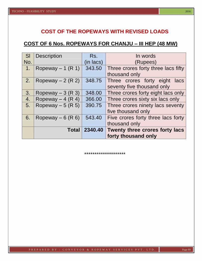
TECHNO – FEASIBILITY STUDY 2016
P R E P A R E D B Y : C O N V E Y O R & R O P E W A Y S E R V I C E S P V T . L T D . Page 89
COST OF THE ROPEWAYS WITH REVISED LOADS
COST OF 6 Nos. ROPEWAYS FOR CHANJU – III HEP (48 MW)
Sl No.
Description Rs. (in lacs)
In words (Rupees)
1. Ropeway – 1 (R 1) 343.50 Three crores forty three lacs fifty thousand only
2. Ropeway – 2 (R 2) 348.75 Three crores forty eight lacs seventy five thousand only
3. Ropeway – 3 (R 3) 348.00 Three crores forty eight lacs only
4. Ropeway – 4 (R 4) 366.00 Three crores sixty six lacs only
5. Ropeway – 5 (R 5) 390.75 Three crores ninety lacs seventy five thousand only
6. Ropeway – 6 (R 6) 543.40 Five crores forty three lacs forty thousand only
Total 2340.40 Twenty three crores forty lacs forty thousand only
********************

TECHNO – FEASIBILITY STUDY 2016
P R E P A R E D B Y : C O N V E Y O R & R O P E W A Y S E R V I C E S P V T . L T D . Page 90
CHAPTER – VIII
CONCLUSION & RECOMMENDATIONS
From the contents in previous Chapters, it is concluded that
6 Nos. Ropeways For CHANJU – III HEP (48 MW) R1, R2, R3, R4, R5, & R6
: Are technically viable and most suitable
Ropeway being Aerial requires little space
Ropeway is more susceptible to high wind, and rain
Ropeway is also less prone to interruption in operation owing to road transportation problems.
Based on the ground profile and the requirement Ropeway is the only solution for transportation of the materials.
It is therefore recommended that
6 Nos. Ropeways at CHANJU – III HEP (48 MW) are technically viable and also the most suitable means of transportation, meeting all the material transport requirements. Intermediate dropping of material near to the Adit point (Unloading Station) will be possible in Ropeway R6.
Forgoing studies were made on the basis of site survey made during Nov 2015, subsequent interaction & data collected from site and your officials. The layout drawing made available to us by you. Before execution of the project, it is advisable to visit the site and verify the data. And takeup the work accordingly.
***************************

TECHNO – FEASIBILITY STUDY 2016
P R E P A R E D B Y : C O N V E Y O R & R O P E W A Y S E R V I C E S P V T . L T D . Page 91
CHAPTER – IX
ELECTRICAL SYSTEM NEEDED FOR THE ROPEWAYS 1. GENERAL The power may be supplied at 33 Kv when a transformer is required. Or if available a LT power supply system can feed the power to the MCC. The entire control operation shall be done from one end of the ropeway. The required control signal shall be taken from driving stations. The control operation shall be done thru VVVF drive. The requirement of the main and sub equipment along with specifications are given as follows:-
Specification for Electrical Equipment
1 HT Isolator
A motor operated off load, triple pole disconnecting switch with earthing device and D/O fuse shall be installed for disconnection of transformer primary for inspection and maintenance purpose as per IS 9920 (Pt1-1985), (Pt 2 , 3 -1982), (Pt4-1985) for each substation.
Model type : Off Load, Motor Operated, air break with earth switch and D/O fuse.
2.
33kV/433V, Oil-immersed Transformer
The transformer shall be designed, manufactured and tested as per particular requirements as specified below:
S. Description Technical requirements / features

TECHNO – FEASIBILITY STUDY 2016
P R E P A R E D B Y : C O N V E Y O R & R O P E W A Y S E R V I C E S P V T . L T D . Page 92
No.
1. Type OIL IMMERSED
2. Duty Indoor
3. Conforming specifications with latest revisions
IS : 2026 (Part –I, II, III & IV) : 1977 IS : 11171:1985 IEC : 60726
4. Capacity 500 KVA
5. Primary 33kV (+ 10%), 3 Phase, 50 Hz (+ 6%)
6. Secondary 433kV (+ 10%), 3 Phase, 50 Hz (+ 6%) base voltage with neutral brought out
7. Winding Copper wound with class H insulation
8. 1. Temp. rise of winding over 50°C ambient temp. (measured by resistance method) 2. Temp. rise oil over 50°C ambient temp.
65°C 55°C
9. Vector Group Dyn11
10. One minute Power frequency withstand voltage
70kV BMS
11. Impulse test withstand voltage
200kV peak
12. Cooling ONAN
13. Tap changing Tappings of HV side with +5% to -7.5% taps range in 2.5% steps with offload
14. Short circuit voltage 4.75%

TECHNO – FEASIBILITY STUDY 2016
P R E P A R E D B Y : C O N V E Y O R & R O P E W A Y S E R V I C E S P V T . L T D . Page 93
at 75°C (Impedance)
15. Termination at H.T. side
H.V. Cable Box
16. Termination at L.T. side
L.V. Cable Box
17. Rated Current 8.75 / 695.6 Amp
18. Approx. Dimension 1.8 M (L) x 1.3 M (W) x 2.09 M (H)
The transformer shall be designed to suppress harmonic voltages, especially the 3
rd and 5
th so as to eliminate
distortion in wave form and the possibility of circulating currents.
The transformer shall be provided with two thermistors in each phase for winding temperature indication and protection, one for warning and one for automatic tripping of feeder breaker when permitted temperature is exceeded. The temp indicator dials shall have linear graduations to clearly read at least every 2°C. The accuracy of WTI shall be better than + 1.5%.
The marshalling box shall be totally enclosed dust proof as per IP – 52 and the dials shall not be mounted above 1600 mm level. In the marshalling box, winding temperature scanner for winding temperature indication shall be provided.
Resistance type embedded temperature detector at hot zone of each phase winding shall be provided with two sets of contacts, for alarm and trip. Calculations shall be submitted for deciding the hot spot zone of the winding.
Minimum 1250 mm clear space shall be provided on all sides of transformers. The clearance between the highest point of the transformer to the ceiling shall be minimum 500 mm.
The transformer shall be housed inside a sheet steel transformer cubicle to prevent both direct and indirect

TECHNO – FEASIBILITY STUDY 2016
P R E P A R E D B Y : C O N V E Y O R & R O P E W A Y S E R V I C E S P V T . L T D . Page 94
contact with the transformer. The degree of protection of transformer cubicle shall be IP-23.
Marshalling Box
The marshalling box shall be metal enclosed vermin and dust proof and shall house the various indicators, terminal blocks etc. the degree of protection shall be at least IP-52 for indoor and IP-55 for outdoor as per IS : 13947 (Pt-1).
The gland plate shall be 2 mm thick and removable type. All cable cores shall terminate only on terminal block. At least 20% termination shall be kept spare.
Earthing
Two nos. tinned copper earthing ternimals shall be provided.
One end of bushing CT shall be earthed.
List of Fittings and Accessories
Off – circuit tap charger
Dial type winding temperature indicator operated by RTD element.
Bushing CT
Bi-directional rollers / flanged wheels
Lifting lugs and jacking pads
Rating and diagram plates
Earthing terminals
Inspection cover
Pockets for thermometer for winding temperature indicator
HV, LV and Neutral bushings
Marshalling box
Tests The Transformer shall be subjected to all the routine tests in accordance with latest version of IS 2026 Part – I and III at manufacturers’ works, in presence of Purchaser representative / consultant unless otherwise waived of in writing by the Company.

TECHNO – FEASIBILITY STUDY 2016
P R E P A R E D B Y : C O N V E Y O R & R O P E W A Y S E R V I C E S P V T . L T D . Page 95
The Contractor shall submit type test certificates for similar transformer.
3.
Motor Control Centre (MCC)
Technical Particulars
S. No.
Specific aspects Technical features
1. Reference standards
IS 13947 (part1-5):1993 – Low Voltage switchgear and control gear assemblies
2. Supply system & variation
Voltage 415 V + 10 %
Phase 3 Ph & Neutral
Frequency 50 Hz + 5 %
3. Neutral system Solidly grounded
4. System Fault Level 50 kA (RMS) for 1 sec
5. Rated Insulation Voltage
2.5 kV for 1 min
6. Construction
a) Type of MCC Single Front Compartmentalised / modular, sheet steel enclosed, floor mounted, free standing.
Draw-out type incomer and out-going and non – drawout type motor feeders.
Maximum operating height shall be 1800 mm and minimum operating height shall be 450 mm from floor level
b) Degree of IP-55

TECHNO – FEASIBILITY STUDY 2016
P R E P A R E D B Y : C O N V E Y O R & R O P E W A Y S E R V I C E S P V T . L T D . Page 96
protection
c) Mounting Vertical, floor mounted, free standing
d) Front Access
Hinged door
e) Back access & Clearance
Back access shall be provided
f) Future extension provision
Provision on both sides by addition of new vertical section.
g) Sheet steel type & thickness
Cold Rolled Sheet steel, 2 mm & 1.6 mm (for door)
h) Paint Shade No. 631 (light grey) of IS 5:1994
i) Cabling Space Side cable Alley
7. Bus bar
a) Main horizontal busbar
3 phase and neutral (RYBN)
b) Busbar Material Aluminum Alloy
c) Max. temp. rise including the specified ambient temp. and derating factor if any
90° C
d) Busbar arrangement
Top horizontal
e) Power feed to outgoing module
Sleeved busbar dropper
f) Insulation Heat shrunk PVC Sleeve
g) Short time withstand current of Neutral Bus
50 kA (RMS) for 1 sec

TECHNO – FEASIBILITY STUDY 2016
P R E P A R E D B Y : C O N V E Y O R & R O P E W A Y S E R V I C E S P V T . L T D . Page 97
h) Short time withstand current of Earth Bus
50 kA (RMS) for 1 sec
i) Colour Coding IS 5578 : 1984 IS 11353 :1985
j) Clearance between phase & phase and phase & Earth / Neutral
25 mm (minimum)
k) Bus bar connectors
All the isolating contacts shall be special bimetallic type
8 Component Details
8.1 Incomer ACB
a) Draw out Electrically operated type
Yes
b) Rated interruption capacity (symmetrical)
50 kA (RMS)
c) Rated making current
105 kA peak
8.1.1
Protection features in ACB
Microprocessor based release shall be provided in the ACB for short circuit protection, over load protection and earth fault protection with provision of signaling memorization till it is acknowledged. The ACB shall have 240 V AC shunt trip releases. The setting range of short circuit protection shall have

TECHNO – FEASIBILITY STUDY 2016
P R E P A R E D B Y : C O N V E Y O R & R O P E W A Y S E R V I C E S P V T . L T D . Page 98
instantaneous setting facility. In addition to above microprocessor based protection release, standby E/F protection shall be provided in Incomer only by using IDMTL relay with NCT.
8.2 Protection features for motors below 30 KW
MPCB with relay function
8.3 MCCB/ACB for outgoing feeder (VFD panel, LDB & Others)
a) Rated interrupting capacity (symmetrical)
50 kA (RMS)
b) Current limiting type
Yes, for all motor feeders.
c) Capacity to protect downstream equipment
Type 2 co-ordination IS 13947 (Part 4/ sec 1):1993
8.4 Contactors (power)
a) Utilization category
AC3 for non reversible feeder AC4 for all reversible feeder
b) Coil voltage (VR)
240 V
c) Drop out voltage
50 % Vr
d) Pick Up 85-110% Vr
e) Rating of contractor
- Minimum size of contactor shall be 22A

TECHNO – FEASIBILITY STUDY 2016
P R E P A R E D B Y : C O N V E Y O R & R O P E W A Y S E R V I C E S P V T . L T D . Page 99
- Contactor size shall be selected as one step higher than actual requirement
f) Auxiliary contacts & rating
2 NO + 2 NC, 10 A, 240 V AC
8.5 Wiring
a) Power Circuit
Insulated (1.1 kV0 flexible Copper wire / strip, pvc insulation
b) Control Circuit
Copper 2.5 sq. mm multi strand PVC wire, insulated, PVC Insulation
8.6 Control Transformer
240 V, 1 –Phase, 50 Hz of minimum 2000 VA rating. Input power to be tapped from incoming side of incomer CB.
8.7 Indicating Lamps LED cluster
8.8 CT& PT As required
8.9 Ammeters For incomer & all motor feeders. Motors rated 7.5 kW and above shall have CT operated Ammeter.
8.10
Voltmeters For incomer
8.11
Energy meter Digital energy meter shall be provided in the incomer panel. The energy meter shall be of 0.5 accuracy class conforming to IEC – 687
8.12
Surge suppressor Across all power contactors
8.13
CT operated overload relays
Motor rated 7.5 kW and above shall have CT operated overload relays
8.14
Spare terminal 20% Spare terminals in control terminal block shall be provided for

TECHNO – FEASIBILITY STUDY 2016
P R E P A R E D B Y : C O N V E Y O R & R O P E W A Y S E R V I C E S P V T . L T D . Page 100
future use
8.15
Identification label Identification label of suitable size on lamicoid sheets or anodized aluminum sheets shall be given for the MCC and for the cubicles.
4.
415 V VFD Drive
The specification of VFD starting Drive, power and control components shall be as mentioned below:
Reference code & Year IS : 1248 (Part I – 1993) (Part 2 – 6,9 -1983) (Part 7,8 -1984)
Title Direct acting indicating analogue electrical measuring instruments & their accessories.
IS:2705-(Part 1-4)-1992 Current transformer
IS : 3156 – (Part1 -4)-1992
Voltage transformer
IS: 3231-(Part1-3)-1992 Electrical Relays for power system protection
IS:5578 -1984 Guide for marking insulated conductor
IS:11353-1985 Guide for uniform marking & identification of conductor and terminals
IS:8623 (Part1 -3)-1993 Low voltage switchgear and control gear assemblies
IS : 10118 (Part 1-4)-1982
Code of practice for selection, installation and maintenance of switchgear and control gear.
IS: 11182 (part1,2-1984) (Part 3,5,6,7-1986)
Guide for evaluation of insulation system of Electrical Equipment
IS: 13947 (part 1-5)-1993 Specification for LV switchgear and control gear

TECHNO – FEASIBILITY STUDY 2016
P R E P A R E D B Y : C O N V E Y O R & R O P E W A Y S E R V I C E S P V T . L T D . Page 101
Technical Specification of 415 V VFD Drive :
S.No. Item Description Technical Specification
1. Input Power Supply
Voltage : 3 Phase, 415 V + 10 % Frequency : 50 Hz + 5 %, 4 wire neutral earthed system, System fault level : 50 kA (RMS) for 1 second. The drive should be designed to operate on an AC supply, which may contain line notching, and up to 5% harmonic distortion.
2. Rated Insulation Level
Insulation voltage = 1.1 kV
One minute p.f withstand voltage: 2.5 kV rms for power circuit 2kV rms for control circuit
3. Rating of feeder MCCB of suitable rating
4. Main horizontal busbar
3 phase & neutral at top
5. Busbar material Aluminium Alloy equivalent to E91EWP as per IS 5082-1981
6. Busbar arrangement
Top horizontal
7. Cabling space Side cable alley or at the back
8. Panel construction VFD Shall preferably be integral module of MCC. However, if separate panel is provided then it shall be :
1. Single front, modular. 2. Vertical, floor mounted, free
standing type and to be mounted on base frame / base channel.
3. Maximum 2350 mm including base channel.

TECHNO – FEASIBILITY STUDY 2016
P R E P A R E D B Y : C O N V E Y O R & R O P E W A Y S E R V I C E S P V T . L T D . Page 102
4. Operating height : 450mm (minimum) and 1800 mm (maximum) from floor height.
5. Panel shall be made from Cold Rolled sheet steel, 2 mm & 1.6 mm (for door)
9. Power feed Sleeved busbar droppers for connection of cables (bottom entry)
10. Application of VFD Frequency converter shall be capable of producing a variable voltage/frequency output for speed regulation.
The VFD shall be factory pre-wired, assembled and tested as a complete package by the VFD supplier. The specific drive, motor and application data shall be preloaded into the operator interface and shall be tested.
11. Applicable Standards for VFD
IEC61800, ANSI, DIN VDE, IEEE519-1992
12. Design ambient temperature
Suitable to operate continuously at 50°C without any de-rating.
13. Harmonic distortion limit
It shall be contained as per IEEE519-1992
14. Basic design particulars & Type of connection
Basic design particulars: - Digital control technology with
sensorless vector control - IGBT based with sine coded PWM
control
- The drive shall have an internal EMC filter capable of meeting the Second environment levels for the

TECHNO – FEASIBILITY STUDY 2016
P R E P A R E D B Y : C O N V E Y O R & R O P E W A Y S E R V I C E S P V T . L T D . Page 103
EMC directive without the need for additional components.
- Shall conform to IEC 146 Type of connection
- MCCB & Semiconductor fuse
- Diode bridge based convertor - DC bus inductor - DC link capacitors - IGBT bridge based inverter - Dv/dt filter as required
- Output reactor - Insulated Gate Bipolar Transistor
(IGBT) power section shall be rated for variable torque application. The power section shall use vector dispersal pulse width modulated (PWM) IGBT gate control algorithm and soft switching IGBT’s to reduce motor terminal dv/dt and allow longer cable length from drive to motor without output filters.
15. Drive controller technology
- Software configurable to sensor less Dynamic Torque Vector mode (single motor)
- Operating the drive with motor disconnected
- Multiple acceleration and deceleration rates.
16. Minimum nominal rating of VFD ( Continuous rating)
130% of the rating of the connecter motor.
17. Overload capacity - 100% continuous

TECHNO – FEASIBILITY STUDY 2016
P R E P A R E D B Y : C O N V E Y O R & R O P E W A Y S E R V I C E S P V T . L T D . Page 104
- Short time duty 150% for one minute
18. Efficiency More than 97% or better at full speed and full load.
19. Crake Chopper Module
Suitably rated Brake Chopper Module for dynamic braking.
20. Braking resister Stainless steel / CI grid resistance suitably rated in enclosure.
5. Squirrel cage Induction Motor
1. Reference standard
IS 325 : 1996 – Rotating Electrical Machine
IS 4722:1992 – Rotating Electrical Machine
IS1231:1974 – Dimensions of three phase foot mounted motor.
IS4691-1985 – Degree of protection provided by enclosures
IS 6362-1971- Designation of methods of cooling for rotating electrical machine
IS4029-1967 – Guide for testing three phase induction motor
IS 2253- 1974- Designation of types of construction and mounting arrangement of rotating electrical machine.
IS21615-2004- Energy Efficiency induction motor
2. Type of motor Squirrel cage induction motor (Energy Efficiency)
3. Rated Voltage 415 V for LT

TECHNO – FEASIBILITY STUDY 2016
P R E P A R E D B Y : C O N V E Y O R & R O P E W A Y S E R V I C E S P V T . L T D . Page 105
4. Duty S1/S4 as per operational requirement
5. Speed (RPM) To be matched with driven equipment.
6. Time to withstand 120% of rated speed
2 minutes
7. Mounting Horizontal / vertical mounting as per application
8. Type of enclosure TEFC
9. Cooling designation
IC-O141 for TEFC type
10. Degree of protection
IP 55
11. Class of insulation F
12. Temperature rise (over ambient temp.50° C)
70°C
13. Method of starting DOL/VVVF drive
14. Special Design criteria for PWM inverter duty motor
Motor shall be designed to withstand additional stress on the windings due to high switching frequency (3kHz average) of the PWM drive.
Insulation system shall be suitable for 1.6kV for rise time of 0.1 sec.
15. Starting current in percentage of rated current (Ist / Ir)
600 %
16. Power factor at rated voltage and load
0.9 or better
17. Efficiency class Class 2 as per IS 12615-2004
18. Starting time at Not more than 10 / 15 sec for 100 %

TECHNO – FEASIBILITY STUDY 2016
P R E P A R E D B Y : C O N V E Y O R & R O P E W A Y S E R V I C E S P V T . L T D . Page 106
100 % and 85% rated voltage with load
voltage.
19. Safe stall time at 110% rated voltage at hot condition
5 -10 sec more than locked rotor withstand time.
20. Thermal time constant, in min.
45 min
21. Margin on Hot thermal Withstand curve
Minimum 10 % over full load current to facilitate relay setting using motor’s rated capacity.
22. Minimum permissible voltage at terminal for starting(with full load)
80% of rated voltage
23. Permissible running time with full load at minimum (75%) allowable voltage
5 min
24. Transient recovery after temporary system disturbance for 0.2 sec and sudden restoration to 70% of rated voltage.
The motor shall be capable to accelerate with load to rated operating point from such condition
25. Fault withstand current and time for thermal box
415 V motors: 50 kA (RMS) for 0.25 sec
26. Withstanding 175 / 2500 micro second

TECHNO – FEASIBILITY STUDY 2016
P R E P A R E D B Y : C O N V E Y O R & R O P E W A Y S E R V I C E S P V T . L T D . Page 107
ability of switching surge of (4U + 5 kV) where U is rated line voltage
27. Winding Material Copper
28. Winding Insulation type
Non-hygroscopic, oil resistant and resistant to flame propagation
29. Whether windings have adequate tropical protection against fungus, corrosion etc provided
Yes
30. Motor terminal box type (for 415 V motor)
It shall be suitable for termination of actual no. and size of cables as per kW rating of the motor considering derating due to site ambient temp as well as method of installation.
31. Degree of protection for terminal boxes
IP-55
32. Bearing Self lubricated antifriction roller bearing
33. Mounting To be filled in by the bidder
34. Earthing of motor body
Each motor frame shall have two distinct grounding pads, one on each side, complete with tapped hole and bolt. The size of the earth connection of the motors to the shop earth grid shall be as per IS:3043-1987
35. The motor shall be provided with adequate & suitable lifting
Yes

TECHNO – FEASIBILITY STUDY 2016
P R E P A R E D B Y : C O N V E Y O R & R O P E W A Y S E R V I C E S P V T . L T D . Page 108
devices and with the foundation bolts.
36. Noise level The noise level shall be as per IS12065:1987 and shall not exceed 85 db at 1 m from motor.
6. Uninterruptible power supply (UPS) system
The UPS system shall be complete with UPS distribution boards, battery bank rack & interconnecting cables. The parallel redundant UPS shall be of 25 % spare capacity over actual requirement, however minimum rating shall be 10kVA.
(1) Technical Parameter
a) Input power supply conditions shall be as below:
Voltage 415V+ 15%, -10%, 3 phase 4 wire AC
Frequency 50 Hz + 4%, -6%
Power factor 0.8 lagging (minimum)
b) Design conditions
Applicable standard
IEC- 60146-4(1986-09), IEC-60146-5(1988-11)
Design ambient temperature
50°C
Acoustic noise 55dB at 1 m
Degree of enclosure
IP 52
c) UPS output shall meet the following requirements
Frequency 50Hz
Voltage regulation +1% nominal for any of the following conditions
1. No. Load to full load
2. 1.0 -0.8 lagging power factor
3. Min. to max DC input voltage

TECHNO – FEASIBILITY STUDY 2016
P R E P A R E D B Y : C O N V E Y O R & R O P E W A Y S E R V I C E S P V T . L T D . Page 109
Voltage transient 10% maximum deviation (average over half- cycle for 100% load application or removal).
Voltage adjustment +5%
Phase separation 120° + 5 % with 100 % load unbalance
Voltage wave form 5% total harmonic distortion(THD) maximum with loads containing upto at least 25 % third and 10% fifth harmonic current
Frequency stability +0.1 % free running
Frequency slew rate
1.0 Hz / second (Maximum)
Frequency adjustment
+2 Hz
Over load capacity 100% continuous
125% for 15 minutes
150% for 30 secs.
d) Storage battery
Voltage As required by the inverter
Protection time 30 Minutes
Type Maintenance free, inverter grade lead acid type
e) Complete operation and control of UPS System shall be microprocessor based with fault diagnostic and data logging features with touch membrane switches along with LCD display, LED based block mimic diagram and Rs – 232 serial port.
f) Provision of contacts shall be kept in the UPS panel for annunciation of abnormal operation / alarm condition in any other operator panel / annunciation panel.
ii) Protection Indication and Annunciation
The protection of the UPS system is to be provided as suitable and required for rectifier and inverter unit and shall

TECHNO – FEASIBILITY STUDY 2016
P R E P A R E D B Y : C O N V E Y O R & R O P E W A Y S E R V I C E S P V T . L T D . Page 110
generally include the following:
a) Rectifier
Reduced setting of current limiting value when cooling system failure occurs
Current limiting during boost charging & float charging
Any other protection as required for particular application
b) Inverter Unit
High or low output / link voltage
Over current on rectifier / inverter output
Low battery voltage
Cooling fan failure
Control & regulation failure
Any other protection as required for particular application
c) The following meters shall be provided
Input & Output voltage, frequency & current
Ammeters for battery charging / discharging
d) The annunciation / alarms shall be provided as listed but need not be limited to:
Earth fault
Load on AC mains / battery
Battery run out warning
Cooling fan failure
e) The following indication are to be provided for the rectifier unit:
Rectifier on
Battery on float / boost charge
Charging failure
Fuse blown
Over current
High / low battery voltage

TECHNO – FEASIBILITY STUDY 2016
P R E P A R E D B Y : C O N V E Y O R & R O P E W A Y S E R V I C E S P V T . L T D . Page 111
Tests
iii) Test at manufacturer’s Work
Routine tests which are required as per relevant IEC standard shall be carried out and test certificate for the same shall be furnished by the Bidder.
7. Illumination
a) Indoor and outdoor illumination system shall be provided for all the premises of Raw Material Handling system, i.e. at each substations, control rooms, and others area.
b) The design and layout of illumination system shall be optimized with regard to consumption of electric power. Suitable energy conservation system shall be considered.
c) All lighting distribution boards, sub-lighting distribution boards, lighting cables, lighting fixtures complete with lamps, junction boxes, pull boxes, GI pipes / conduits, MS brackets, clamps and all other items / accessories as required shall be provided by the bidder. The Bidder shall also provide fans, 15 /5A 3 pin receptacles, low voltage transformers inclusive of all consumables, sundry materials and hardware to make the system complete in all respect for efficient and trouble free operation.
d) The lighting distribution boards for conveyor gallery shall be installed at the non drive end of each gallery. 230 V lighting receptacles shall be provided along the gallery on either side at a distance of 15 m alternately. Whereas 24 V transformer for hand lamps shall be provided near the LDBs with sockets along the gallery.
e) The illumination system shall be designed as per IS 3646 : 1992. It shall have energy saving features. The level of illumination, type of fittings, maintenance factor to be considered is as given below:
Area Type of light fittings Lux level
MF
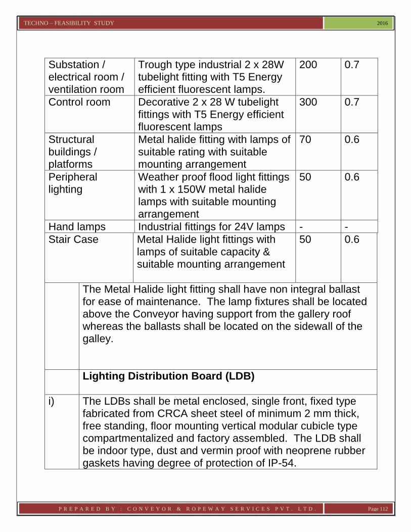
TECHNO – FEASIBILITY STUDY 2016
P R E P A R E D B Y : C O N V E Y O R & R O P E W A Y S E R V I C E S P V T . L T D . Page 112
Substation / electrical room / ventilation room
Trough type industrial 2 x 28W tubelight fitting with T5 Energy efficient fluorescent lamps.
200 0.7
Control room Decorative 2 x 28 W tubelight fittings with T5 Energy efficient fluorescent lamps
300 0.7
Structural buildings / platforms
Metal halide fitting with lamps of suitable rating with suitable mounting arrangement
70 0.6
Peripheral lighting
Weather proof flood light fittings with 1 x 150W metal halide lamps with suitable mounting arrangement
50 0.6
Hand lamps Industrial fittings for 24V lamps - -
Stair Case Metal Halide light fittings with lamps of suitable capacity & suitable mounting arrangement
50
0.6
The Metal Halide light fitting shall have non integral ballast for ease of maintenance. The lamp fixtures shall be located above the Conveyor having support from the gallery roof whereas the ballasts shall be located on the sidewall of the galley.
Lighting Distribution Board (LDB)
i)
The LDBs shall be metal enclosed, single front, fixed type fabricated from CRCA sheet steel of minimum 2 mm thick, free standing, floor mounting vertical modular cubicle type compartmentalized and factory assembled. The LDB shall be indoor type, dust and vermin proof with neoprene rubber gaskets having degree of protection of IP-54.

TECHNO – FEASIBILITY STUDY 2016
P R E P A R E D B Y : C O N V E Y O R & R O P E W A Y S E R V I C E S P V T . L T D . Page 113
ii) The LDB shall have enclosed busbar chamber at the top, vertical busbars for outgoing feeders and cable compartments separately. Maintenance access shall be provided from front only after opening the front covers/doors.
iii) The main and tap-off busbars shall be high conductivity copper and shall be colour coded. The busbars shall be adequately sized to limit the temperature rise up to 35°C over ambient of 50°C under full load current.
iv) Each LDB shall have one incomer and outgoing feeders as per requirement. TPN MCCBs shall be provided for incomer. Whereas outgoing feeders shall have DP MCBs.
v) Each LDB shall have 24 hour timer as well photoelectric sensor, contactor and bypass circuit breaker scheme for illumination energy saving provision during day time.
vi) Each outgoing feeder will feed lighting power to the respective Sub Distribution Board (SDB) for lighting. 30% spare outgoing feeders shall be provided for each LDB with minimum of 2 nos.
vii) Cable entries shall be made from the bottom. Detachable cable gland plates of minimum 3 mm thick sheet steel with knock-out type cable entry holes shall be provided.
viii) Each LDB shall have one no. 0-500V Voltmeter (size 72 mm X 72 mm) with Selector Switch and 3 nos. Indication Lamps for R-Y-B indication in each incoming cubicle.
Sub Distribution Board (SDBs)
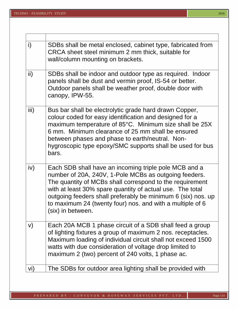
TECHNO – FEASIBILITY STUDY 2016
P R E P A R E D B Y : C O N V E Y O R & R O P E W A Y S E R V I C E S P V T . L T D . Page 114
i)
SDBs shall be metal enclosed, cabinet type, fabricated from CRCA sheet steel minimum 2 mm thick, suitable for wall/column mounting on brackets.
ii) SDBs shall be indoor and outdoor type as required. Indoor panels shall be dust and vermin proof, IS-54 or better. Outdoor panels shall be weather proof, double door with canopy, IPW-55.
iii) Bus bar shall be electrolytic grade hard drawn Copper, colour coded for easy identification and designed for a maximum temperature of 85°C. Minimum size shall be 25X 6 mm. Minimum clearance of 25 mm shall be ensured between phases and phase to earth/neutral. Non-hygroscopic type epoxy/SMC supports shall be used for bus bars.
iv) Each SDB shall have an incoming triple pole MCB and a number of 20A, 240V, 1-Pole MCBs as outgoing feeders. The quantity of MCBs shall correspond to the requirement with at least 30% spare quantity of actual use. The total outgoing feeders shall preferably be minimum 6 (six) nos. up to maximum 24 (twenty four) nos. and with a multiple of 6 (six) in between.
v) Each 20A MCB 1 phase circuit of a SDB shall feed a group of lighting fixtures a group of maximum 2 nos. receptacles. Maximum loading of individual circuit shall not exceed 1500 watts with due consideration of voltage drop limited to maximum 2 (two) percent of 240 volts, 1 phase ac.
vi) The SDBs for outdoor area lighting shall be provided with

TECHNO – FEASIBILITY STUDY 2016
P R E P A R E D B Y : C O N V E Y O R & R O P E W A Y S E R V I C E S P V T . L T D . Page 115
contactor (matched with TP and N switch rating), 20A, 1 pole MDBs as outgoing feeders, frequency compensated timer switch, push buttons for automatic control of area lighting with provision for manual override.
vii) The incoming TPN MCBs shall be of 63A rating with suitable nos. of outgoing feeders of 20A MCB with 30% spare MCBs.
Lighting Fixtures
i) Fixtures shall be suitable for 20 mm conduit entry and 16 SWG GI earth wire connection. Necessary conduit to pipe adapters shall be furnished for fixtures suitable for pipe entry.
ii) High bay fixtures shall have provision for vibration damper to ensure rated lamp life.
iii) Fixtures shall be fully wired up to the respective terminal blocks, suitable for connection of PVC wires of following sizes:-
1.5 sq.mm copper (stranded) for fixtures with below 150W lamps and 2.5 sq.mm copper (stranded) for fixtures above 150W lamps.
8. Receptacles with Socket, Plug & Switch
i) The receptacles to be installed shall be of the following types :-
Type RA – 5A, 240V AC, 2 pole, 3 pin with third pin earthed, decorative type suitable for flush mounting in office areas and control rooms. The switch shall also be flush mounted piano/modular type.
Type RB – 16A, 240V AC, 2 pole, 3 pin with third pin earthed, decorative type suitable for flush mounting in office areas and control rooms. The switch shall also be flush mounted piano type.

TECHNO – FEASIBILITY STUDY 2016
P R E P A R E D B Y : C O N V E Y O R & R O P E W A Y S E R V I C E S P V T . L T D . Page 116
Type RC – 20A, 240V AC, 2 pole, 3 pin with third pin earthed, industrial type wall/column mounted metal clad gasketted construction, 20 mm conduit entry, screwed metal cover tied to it by metallic chain, weatherproof, suitable for indoor and outdoor installation.
ii) Receptacles type RA/RB/RC shall be fed from nearest SDB.
iii)
The conduit box of receptacle shall be provided with earthling screws with washer and nuts, welded on surface for grounding with 16 SWG GI wires. Arrangement shall be provided inside conduit box for grounding of third pin.
iv) Receptacles type RC shall be of cast steel/aluminium heavy duty type.
v) Shrouded type plug shall be provided with corresponding matching arrangement at sockets to prevent accidental contact with finger during plug insertion.
8A
Repair network/Welding Distribution
One no. of Feeder for welding power with spare are to be provided in each electrical room. Welding Receptacle: Welding receptacles shall be 63A, 415V, AC, 3 phase, 50 Hz with socket outlet, interlocked 63A TPH switch fuse & plug. The receptacle shall be dust and vermin proof, gasketted industrial type with degree of protection IPW-55 and interlocked type. For outdoor installations 2 mm thick sheet steel canopy shall be be provided.
9. Local Control Station (LCS)
LCS shall have two push buttons, viz. stop push button and start push button. The stop push button shall be of red colour, mushroom headed with “press to lock” and lockable

TECHNO – FEASIBILITY STUDY 2016
P R E P A R E D B Y : C O N V E Y O R & R O P E W A Y S E R V I C E S P V T . L T D . Page 117
type feature. The start push-button shall be of green colour and shrouded spring return type. The LCS shall have one emergency switch also. The local control station shall be in line with the following specifications :-
Enclosure
:
Degree of protection shall be IP-55. Enclosure shall be made of stainless steel
Push Button contact utilization category
: AC 11
Insulation voltage : 600V
Contact combination : 2 NO + 2 NC
The relevant drawing of the LCS shall be firmly fixed on the inside face of the LCS cover. The enclosure shall have tapered canopy over them. A detachable gland plate at bottom or a suitable knock-out shall be provided for cable entry from bottom. The LCS shall have industrial type heavy duty terminal block and the terminals shall be suitable for termination 2.5 sq. mm copper conductors. Each terminals –block shall have 2 nos. terminal as spare terminals. “Drive ON”, “Drive OFF” and control station inscription shall be marked on corrosion resistant metal strip. Identification label on each push-button shall be etched / engraved on corrosion resistant metal strip or plastic sheet 3 mm thick and shall be fixed on the front side of individual local control station with few threading screws.

TECHNO – FEASIBILITY STUDY 2016
P R E P A R E D B Y : C O N V E Y O R & R O P E W A Y S E R V I C E S P V T . L T D . Page 118
The Local Control Station shall have following: Push Button for START / OPEN Push Button for STOP /CLOSE Push Button for ON Push Button for OFF Push Button for TRIP Indicating lamps shall be LED block type, and suitable for panel mounting. Lamps shall have coloured translucent lamp cover. Lamps shall be replaceable from the front. Lamp related with push buttons shall be mounted directly above the respective push buttons. Each Drive shall have LCS.
10. Cable & Cabling Accessories
i) HT Cable Heavy duty power cable, compact circular stranded (rm/v), A1 conductor, provided with screening of semi conducting compound, XLPE insulated (Type-C), provided with insulation screening over individual cores, consisting of extruded semi conducting compound followed by lapped semi conducting compound and copper tapes, cores laid up together with suitable fillers in the interstices, covered with extruded PVC inner sheath (Type ST2), galvanized flat steel strip armoured and extruded PVC outer sheathed cable suitable for 33 KV system, conforming to IS:7098 (Pt-II), 1985. XLPE cable shall be un-earthed grade.
ii) HT Power Cable Accessories Only heat shrinkable type cable joints and terminations shall

TECHNO – FEASIBILITY STUDY 2016
P R E P A R E D B Y : C O N V E Y O R & R O P E W A Y S E R V I C E S P V T . L T D . Page 119
be provided with the following features :- a. Cable joints and terminations shall be as per IEEE-48
and Class-I b. Test Report (as per VDE 0278) from Government
approved test laboratory shall be furnished c. The stress control shall be achieved by heat shrink
black tubing of suitable specifications. d. Track resistance properties of insulating tubing, sealant
and adhesives shall be duly supported by test certificates from a Government approved laboratory
iii) LT Power Cable LT power Cables shall be 1.1 KV grade multicore heavy duty PVC insulated, PVC sheathed flat steel strip armoured with Aluminium Conductor as per IS:1554 (Part-1) 1988. The cable shall be suitable for steady conductor temperature of 70°C . The insulation of inner and outer sheaths shall be of extruded PVC type ST1 as per IS:5831-1984. Minimum and maximum cross-section of conductor of LT power cables shall be 6 sq.mm and 240 sq.mm respectively.
iv) Control Cable 1.1 KV grade, multi core multi strand, round steel wire armoured annealed copper conductor, PVC insulated, PVC sheathed and shall conform to IS:1554 (Part-I0 1976. The insulation of inner and outer sheaths shall be of extruded PVC type ST1 as per IS:5831-1984. Minimum copper conductor size to be used 1.5 sq.m.
11. Safety Appliances

TECHNO – FEASIBILITY STUDY 2016
P R E P A R E D B Y : C O N V E Y O R & R O P E W A Y S E R V I C E S P V T . L T D . Page 120
Safety appliances as safety chart, rubber hand gloves, rubber mats, fire extinguisher etc. shall be provided in Electrical Room.
12. Earthing System Earthing shall be provided covering buildings, structures, columns, electrical systems, equipment etc. of proposed Raw Material Handling System in accordance with code of practice for earthing as specified in IS:3043-1987 and shall also comply with relevant clauses of Indian Electricity Rules. The minimum earth resistance shall be less than 0.5 ohm. The main underground earthing shall comprise of earth pits, earth strips and risers. GI Pipes and galvanised MS flats shall be used for earthing and earth grids. All earthing connections shall be of sufficient section to carry fault current for 3 seconds. All joints shall be made with pressure type fitting or welded. Underground earthing ring shall have 75 X 10 mm galvanized steel flat. Whereas earthig for all HT switchgear, LT switchgear i.e. PCC, MCC, PDB, structures, cable trays shall be with 50X6 mm flat galvanized steel flat. For other electrical equipment suitable size of earth conductor shall be provided. Earth electrodes shall have facilities for measurement of resistance and watering during dry season. The successful Tenderer shall submit all test reports and all calculations for earthing to Purchaser/Consultant for approval.
13. Lightning Protection

TECHNO – FEASIBILITY STUDY 2016
P R E P A R E D B Y : C O N V E Y O R & R O P E W A Y S E R V I C E S P V T . L T D . Page 121
Lightning protectin system shall be designed as per IS:2309-1989. Lightning mast shall be provided on structures and separate earthing masts of steel structure shall be provided to protect all equipment / structure. Vertical air termination rods shall be of 25 mm dia galvanized steel rods. Whereas horizontal air termination conductor and down conductor from air terminals (mast to earth electrode shall be of 50 X 6 sq. mm size galvanized steel strip. Lightning protection system shall have separate dedicated earth pits i.e. other than equipment earthing system earth pits.
14. DC Voltage Power Pack The power pack shall be suitably designed to provide output voltage of + & - 24 VDC & adjustable + 10% of rated voltage and load current limit from 115% down to 10% of rated current. The power pack shall be fully protected against over load and short circuit RFI filter shall be incorporated in input line to prevent RF interference from main supply. The output voltage shall be electrically floating from ground. Setting regulation shall be at least 20mV, load regulation + 0.2% with transient recovery of approx. 100usec. It shall have recovery within regulation band for a load change from 10% to 90% and the output adjustability from 20.4V to 32.4V. The ripple and noise shall be within 1 mv rms. The unit shall be provided with voltmeter and ammeter.
15. Fire Detection & Alarm System

TECHNO – FEASIBILITY STUDY 2016
P R E P A R E D B Y : C O N V E Y O R & R O P E W A Y S E R V I C E S P V T . L T D . Page 122
Fire detection and alarm system shall comprise of Automatic Soft Addressable Modular design main fire alarm control panels, Dual Optical Smoke & Heat MULTI sensors, Blue LED Optical Smoke & Heat MULTI Sensors, Optical Some/Heat/CO Gas MULTI Sensors, manual call points, electronic wall mounted alarm sounder/flasher/speech combined devices. The system shall be intelligent in operation with advanced decentralized intelligence technology. Each detector will have its own processor with algorithms built in the device to take a fire or fault decision.
16. Cables and GI Pipes/conduits already mentioned above
i) Cables a. All control cables shall be conforming to IS;1554 (Part-
II) latest version or relevant Indian Standards as applicable. The cables shall be FRLS type.
b. The power wiring within cubicle shall be done with minimum 1.5 sq.mm copper conductor.
c. Cable lying shall be as per IPSS::2-07-040-88 d. Cable entry to panels/junction boxes shall be through
suitable gland plates and glands. e. Compensating cable shall be suitable for K or S type
Thermocouple conforming to IS:8784/78
ii) GI Pipes/conduits a. GI Pipes /conduits shall be used to provide protection
against mechanical damage to cables. These shall be radium gauge, hot dip galvanized, electric resistance welded (ERW) screwed
b. Not more than 40% of GI pipe cross sectional area will be used (blocked).
c. Where a number of GI pipes or conduits are run in a bunch adequate number of spare pipes (minimum two

TECHNO – FEASIBILITY STUDY 2016
P R E P A R E D B Y : C O N V E Y O R & R O P E W A Y S E R V I C E S P V T . L T D . Page 123
nos. of comparable diameters) shall be provided for any unforeseen use
iii) Earthing The method adopted for system as well as equipment earthing shall be in accordance with IS:3043-1987 and shall also comply with relevant clauses of latest Rules & Regulations of electrical authority of Government of India. The earthing system shall conform to IE rules and latest revision of relevant Indian Standards. Separate, independent electrical and electronic earthing pits and associated earthing grids shall be considered for grounding of electrical and electronics equipment for new SAF plant. The earth resistance of electronic system shall be less than 0.5 ohm.
*************************

TECHNO – FEASIBILITY STUDY 2016
P R E P A R E D B Y : C O N V E Y O R & R O P E W A Y S E R V I C E S P V T . L T D . Page 124
Annexure - 1 CODES & STANDARDS
All work shall generally conform to the requirements of the latest revisions and / or replacements of the following or any other relevant Indian Standard specifications and codes of practice. IS : 210 : Grey Iron Casting IS : 226 : Structural Steel (Standard Quality) IS : 269 : Ordinary and low heat Portland cement IS : 277 : Galvanized steel sheets (Plain and corrugated) IS : 325 : Three- phase induction motor IS : 383 : Coarse and fine aggregates from natural sources
for concrete IS : 432 (Part- I)
: Mild Steel and medium tensile steel bars and hard – drawn steel wire for concrete reinforcement
IS : 456 : Code of practice for plain and reinforced concrete IS : 516 : Methods of test for strength of concrete IS : 692 : Paper insulted lead- sheathed cables for electric
supply IS : 800 : Code of Practice for use of structural steel in
general building construction IS : 802 : Code of Practice for use of structural steel in
overhead transmission line towers IS : 802 : Code of Practice for use of steel tubes in general
building construction IS : 808 : Rolled steel beams, channels and angle sections IS : 813 : Scheme of symbols for welding IS : 814 : Covered electrodes for metal arc welding of
structural steel IS : 815 : Classification and coding of covered electrodes for
metal arc welding of mild steel and low alloy high tensile steel

TECHNO – FEASIBILITY STUDY 2016
P R E P A R E D B Y : C O N V E Y O R & R O P E W A Y S E R V I C E S P V T . L T D . Page 125
IS : 816 : Code of Practice for use of metal arc welding for general construction in mild steel
IS : 817 : Code of Practice for training and testing metal arc welders
IS : 818 : Code of Practice for safety and health requirements in electric and gas welding and cutting operation
IS : 822 : Code of Practice for inspection of welds IS : 919 : Recommendations for limits and fits for
Engineering IS : 961 : Structural Steel ( High Tensile) IS :1030 : Carbon Steel castings IS :1038 : Steel doors, windows and ventilators IS :1077 : Common Burnt clay building bricks IS :1139 : Hot rolled mild steel, medium tensile steel and
high yield strength steel deformed bars for concrete reinforcements
IS :1148 : Rivet bars for structural purposes IS :1149 : High tensile rivet bars for structural purposes IS :1161 : Steel Tubes for structural purposes IS :1199 : Method of sampling and analysis of concrete IS :1200 : Method of measurement of steelwork and
ironwork IS :1239 : Mild Steel Tubes IS :1363 : Black hexagon bolts, nuts and lock nuts (Dia 6 to
30 mm) and black hexagon screws (Dia 6 to 24 mm)
IS :1369 : Precision and semi-precision hexagon bolts, screws, nuts, and locknuts (Dia range 6 to 39 mm)
IS :1367 : Technical supply conditions for treaded fasteners IS :1442 : Covered electrodes for the metal arc welding of
high tensile structural steel IS :1489 : Portland- pozzolana Cement

TECHNO – FEASIBILITY STUDY 2016
P R E P A R E D B Y : C O N V E Y O R & R O P E W A Y S E R V I C E S P V T . L T D . Page 126
IS :1554 : PVC insulted cables for working voltages from (Part-I) 3.3KV up to and including 11KV
IS :1566 : Hard- drawn steel wire fabric for concrete reinforcement
IS :1608 : Method for tensile testing of steel products other than steel strip, wire and tube
IS :1730 : Dimension for steel plate, sheet and strip for structural and general engineering purpose
IS :1731 : Dimensions for steel flats for structural and general engineering purpose
IS :1786 : Cold-worked steel high strength deformed bars for concrete reinforcement
IS :1804 : Fibre cores for steel wire ropes IS :1852 : Rolling and cutting tolerances for hot-rolled steel
products IS :1977 : Structural Steel (Ordinary Quality) St-42-0 IS :2026 : Power transformers IS :2062 : Structural Steel (fusion welding quality) IS :2074 : Ready mixed paints, red oxide zinc chromate
priming IS :2250 : Code of Practice for preparation and tools and
masonry mortars IS :2315 : Thindles for wire ropes IS :2363 : Glossary of terms relating to wire ropes IS :2516 : Circuit Breakers IS :2959 : Contractors for voltages not exceeding 1000 A.C.
or 1200 D.C. IS :3757 : High Tensile Friction Grip Bolts. 12-4 IS :3937 : Recommendations for socketing of wire ropes IS :3975 : Mines steel wires, strips and tapes for armoring of
cables IS :4000 : High strength bolts in steel structure IS :5831 : PVC insulation and sheath of electric cables

TECHNO – FEASIBILITY STUDY 2016
P R E P A R E D B Y : C O N V E Y O R & R O P E W A Y S E R V I C E S P V T . L T D . Page 127
IS :7098 (Part – II)
: Cross linked polyethylene insulated PVC sheathed cables
IS :7215 : Tolerances for fabrication of steel structures IS :8130 : Conductors for insulated electric cables and
flexible cords IS :9413 : Rope guide Rollers for Haulage Rope IS :9595 : Recommendations for metal arc welding of carbon
and carbon manganese steels IS :9706 : Aerial Ropeways for transportation of material –
code of practice for design & construction IS :10891 : Steel wire ropes for Aerial Ropeways
**********************

TECHNO – FEASIBILITY STUDY 2016
P R E P A R E D B Y : C O N V E Y O R & R O P E W A Y S E R V I C E S P V T . L T D . Page 128
Annexure – 2 Calculation sheet for Anchor Foundation

TECHNO – FEASIBILITY STUDY 2016
P R E P A R E D B Y : C O N V E Y O R & R O P E W A Y S E R V I C E S P V T . L T D . Page 129
Annexure – 3 Calculation sheet for Trestle Footing(TYP)


![[2 ND CYCLE] OF - gpgcseema.edu.ingpgcseema.edu.in/pdf/ssr.pdf · HPPCL Himachal Pradesh Power Corporation Private Limited HPPSC Himachal Pradesh Public Service Commission HPSEB](https://img.dokumen.tips/doc/110x75/5ac69a947f8b9a12608e44ff/2-nd-cycle-of-himachal-pradesh-power-corporation-private-limited-hppsc-himachal.jpg)