Embed Size (px)
Citation preview

IEEE TRANSACTIONS ON SMART GRID, VOL. 9, NO. 5, SEPTEMBER 2018 4383
High Speed Digital Distance Relaying SchemeUsing FPGA and IEC 61850
Xingxing Jin, Student Member, IEEE, Ramakrishna Gokaraju, Senior Member, IEEE,Rudi Wierckx, and Om Nayak, Senior Member, IEEE
Abstract—Full-cycle Fourier and cosine phasor filteringsystems are typical implementations of numerical distance relayswith a response time of close to one cycle. Fast subcycle numericaldistance elements are useful, especially for extra high volt-age/UHV transmission systems (400 kV and above). Fast subcyclenumerical relaying methods such as half-cycle Fourier method,phaselets, least error squares, traveling wave, and wavelet basedmethods have been proposed in the literature. In this paper, firstimprovements to the phaselet-based distance relaying method areproposed by taking the magnitude errors and the phase angleerrors into account. An adaptive Mho characteristic based onthe phasor estimation errors is used to achieve a fast and securetrip decision. The quality of the estimated values in time domainis analyzed mathematically using a transient monitoring index.Second, the scheme is implemented on a field programmablegate arrays (FPGAs) board, which provides fast computationspeeds due to its powerful parallel processing units. The proposedrelay is tested using hardware-in-the-loop simulations and areal time digital simulator. Third, the Ethernet-based protocols(IEC 61850 sampled value and generic object oriented substationevents protocols) are implemented on the FPGA and used to ver-ify the performance of the proposed relay in digital substationenvironments.
Index Terms—Sub-cycle algorithms, adaptive protection,FPGAs, IEC 61850, hardware-in-the-loop simulations.
I. INTRODUCTION
H IGH speed protection is desirable for extra high voltage(EHV) transmission lines (400 kV and above). It is
reported that for every one millisecond saved in fault clearingtime, the stability limit of the transmission system goes up by15 MW [1].
Full-cycle discrete Fourier transform (FCDFT) needs onecomplete cycle of samples to exclude pre-fault samples andobtain an accurate fundamental phasor. Some sub-cycle lin-ear numerical filtering methods have been proposed in [2]–[8].
Manuscript received August 31, 2016; revised December 2, 2016; acceptedJanuary 6, 2017. Date of publication January 19, 2017; date of current ver-sion August 21, 2018. Part of this research work was presented in the IEEEPES General Meeting, Student Poster Contest entitled “High Speed DigitalDistance Relaying Scheme for Extra High Voltage Transmission Lines,” July17–21, 2016. Paper no. TSG-01178-2016.
X. Jin and R. Gokaraju are with the Department of Electrical and ComputerEngineering, University of Saskatchewan, Saskatoon, SK S7N 5A9, Canada(e-mail: [email protected]; [email protected]).
R. Wierckx is with RTDS Technologies Inc., Winnipeg, MB R3T 2E1,Canada (e-mail: [email protected]).
O. Nayak is with Nayak Corporation, Princeton, NJ 08558 USA (e-mail:[email protected]).
Color versions of one or more of the figures in this paper are availableonline at http://ieeexplore.ieee.org.
Digital Object Identifier 10.1109/TSG.2017.2655499
In [2] and [3], half-cycle DFT (HCDFT) is suggested wherebyonly half-cycle samples are used to estimate the phasors;this makes the convergence speed faster than for the FCDFTmethod. However, HCDFT is known to lose the ability to rejecteven harmonics. It also has difficulties removing the decayingDC offset. Half-cycle least error square (HCLES) models thedecaying DC component and harmonics using the Taylor seriesexpansion, but the performance depends on the accuracy of theestimated parameters of the decaying DC, especially when thedecaying DC rates are fast. In [4] and [5], three off-line look-up tables are added to improve the estimation of the decayingDC parameters. A Clarke transformation based DFT algorithmis proposed in [6]. The main focus is on reducing measurementerrors for off-nominal frequency conditions. Another linearfiltering method found to be reliable is the Kalman filteringmethod [7]. The estimation is stable in the presence of noiseand harmonics, but takes more than half a cycle to obtain a sta-ble estimation due to the large number of computations neededto find the state variables in each time step. Wavelet trans-form (WT) techniques have been reported for digital distanceprotection [8]. Using the WT multiresolution analysis (MRA)described in [8], the fundamental phasor can be extracted fasterthan FCDFT. However, the performance is affected by thedecaying DC component. The response is fast but could beinsecure as the impedance trajectories move in and out of theprotection zone before settling [8]. To overcome this issue, thedata window is reset once a disturbance is detected [8], to givea more stable response. A pre-bandpass filter is used to removethe DC component, but this introduces a time delay. Anothertype of fault detection is based on artificial intelligence models.In [9], a convolutional sparse autoencoder (CSAE) was usedto learn features from voltage/current signals. Fault detectionwas done by applying a classifier on the feature vectors and theoperation time was within one cycle. However, system tran-sients such as CT saturation and CCVT transient errors werenot considered, which may affect the classification accuracyand speed.
In this paper, a phaselet-based distance relaying schemeis developed to achieve a fast sub-cycle response. Phaseletsare partial integrals of products of the waveform samplesand the sinusoidal/cosine coefficients specified by a datawindow. They can be combined into phasors over a vari-able length window that is an integer multiple of the basicphaselet. References [10]–[12] describe phaselet scheme andtesting using offline computer simulations for transmission linedistance and current differential protection.
1949-3053 c© 2017 IEEE. Personal use is permitted, but republication/redistribution requires IEEE permission.See http://www.ieee.org/publications_standards/publications/rights/index.html for more information.
4384 IEEE TRANSACTIONS ON SMART GRID, VOL. 9, NO. 5, SEPTEMBER 2018
Fig. 1. Adaptive filtering window concept.
In this paper, the phaselet method is modified by taking themagnitude errors and the phase angle errors into considera-tion to obtain a secure trip decision. The probability densityfunctions for the magnitude and phase angle errors are found.The standard deviations are obtained using a mathematicalequation for magnitude errors and a numerical solution forphase angle errors. The adaptive Mho reach is set based on themaximum possible errors. The quality of the estimated valuesin time domain is analyzed mathematically using a transientmonitoring index.
The second innovative component of the research workis the hardware implementation of the proposed algorithmdescribed herein on FPGA. The phaselet-based algorithm isparallel in nature and is implemented using the parallel natureof FPGAs. This speeds up the calculations compared to digitalsignal processor (DSP) implementations.
The third innovative component of this paper is imple-menting the proposed digital relay using IEC 61850 SampledValue (SV) and Generic Object Oriented Substation Events(GOOSE) protocols [13]. Testing and the performance of theproposed relay is done using hardware-in-the-loop simulationswith a real-time digital simulator (RTDSTM).
II. PHASELET-BASED DISTANCE PROTECTIVE RELAY
The phasor estimation using FCDFT is given as follows:
X̂c = 2
N·
N−1∑
k=0
x(k) · cos
(2π · k
N
), (1)
X̂s = 2
N·
N−1∑
k=0
x(k) · sin
(2π · k
N
)(2)
X̂ = X̂c − jX̂s, (3)
When a fault occurs the filter window spans two partialsample sets: pre-fault system measurements and during-faultsystem measurements. Therefore, phasor estimation using theFCDFT algorithm has an inherent error due to the fixed full-cycle window. To address this issue, a phaselet-based variablewindow filtering technique is developed. Phaselets are partialintegrals of products of the waveform samples and the sinu-soidal/cosine coefficients specified by a data window. They arecombined into phasors over a set of linearly increasing windowsizes, as shown by the dashed line boxes in Figure 1. Eachbox in the figure represents a filtering window (there would
be 20 of them in one full cycle and each phaselet includes 4samples). The phaselets are calculated:
Plc(p) =p·P+P−1∑
k=p·Px(k) · cos
(2π · k
N
), (4)
Pls(p) =p·P+P−1∑
k=p·Px(k) · sin
(2π · k
N
), (5)
where constant P is the number of samples per phaselet and isset to 1/20 of one cycle so that the changes in voltage/currentmeasurements can be captured as early as possible. There are20 phaselets in one cycle and the phaselet index p ranges from0 to 19 for the first cycle samples. Plc(p) is the cosine part ofthe pth phaselet and Pls(p) is the sine part.
The sum of the phaselets for window W(n) is given by:
Pc(n) =n∑
p=n− W(n)P +1
Plc(p), (6)
Ps(n) =n∑
p=n− W(n)P +1
Pls(p), (7)
where n is the phasor index and W(n) is the adaptive windowsize which increases in a linear fashion from 1/20 cycle to 1cycle. Pc(n) is the cosine part of the sum of all the phaseletsinside the specified window W(n) and Ps(n) is the sine part.X̂c(n) and X̂s(n) can be estimated from Pc(n) and Ps(n) [14],as depicted in:
X̂(n)=[
X̂c(n)
X̂s(n)
]=
[C1(n) C2(n)
C2(n) C3(n)
]−1[Pc(n)
Ps(n)
], (8)
C1(n)=W(n)−1∑
k=0
cos2(
2π · k
N
), (9)
C2(n)=W(n)−1∑
k=0
cos
(2π · k
N
)sin
(2π · k
N
), (10)
C3(n)=W(n)−1∑
k=0
sin2(
2π · k
N
). (11)
When W(n) equals to N, C2(n) will be zero using theorthogonality principle of sine and cosine terms. X̂c(n) andX̂s(n) are orthogonal and Equation (8) will be equivalent toEquations (1), (2). When W(n) is between 0 and N except N/2,C2(n) will not be zero. The precomputed coefficient matrixC−1(n) in Equation (8) is needed.
Under normal conditions, the phaselets are summed overone cycle and the filter window W(n) is fixed to N, gener-ating an equivalent of FCDFT, as indicated by the solid linebox in Figure 1. Once a disturbance is detected (the detectionlogic is described in the following paragraphs), the filteringwindow immediately shrinks to P. Because all pre-fault mea-surements are blocked by the window, the estimated phasorresponds more quickly to the change in voltage and currentmeasurements. As new phaselets accumulate, the window sizeis increased until it reaches one full cycle N, as indicated by

JIN et al.: HIGH SPEED DIGITAL DISTANCE RELAYING SCHEME USING FPGA AND IEC 61850 4385
Fig. 2. Frequency responses of the phaselet-based filters.
Fig. 3. Logical implementation of disturbance detector. |I1|′, |I2|′, and |I0|′are current phasor magnitudes from two cycles before.
the dashed line boxes in Figure 1. Unless another new distur-bance is detected, phaselets will continue to be combined toform an FCDFT in a recursive manner. The accuracy of theestimated phasor improves as the window expands.
Figure 2 shows the frequency response of the phaselet-basedfilters with various window sizes. Very small windows (smallerthan 0.4 cycles) have little capability to reject harmonics andDC offset but, as the window expands, the harmonic responseand DC response improve until they are eventually equivalentto FCDFT. Importantly, the filter loses the ability to reject evenharmonics when the window equals to a half cycle (HCDFT).The gain of the filter for DC is 0.64.
In this research, a mimic filter is used to remove thedecaying DC component prior to the phaselet calculation.A disturbance detector is used for the purpose of initiatingthe adaptive phasor estimation. The inputs of the disturbancedetector are the present sequence currents and the corre-sponding measurements from two cycles earlier, as shown inFigure 3. The magnitude of the change in currents are eval-uated against two times the cut-off threshold, which is setat 2% [15] of the steady state value. If the change of anysequence current exceeds this limit, a disturbance operand willbe sent to the distance element.
A. Transient Monitoring and Error Analysis
If we denote the reconstructed sample as x̌(n), then
x̌(n) = X̂c(n)cos
(2π · (n + 1)P − 1
N
)
+ X̂s(n)sin
(2π · (n + 1)P − 1
N
). (12)
Figure 4 compares the original sampled values and thereconstructed values from X̂c(n) and X̂s(n). The instantaneousoutput of the mimic filter is also given to show the phase shift
Fig. 4. Transient monitor.
Fig. 5. Probability density function for phasor magnitude and angle.
TABLE ISTANDARD DEVIATION & REACH FOR DIFFERENT FILTERING WINDOWS
between them. The window size is dynamically changed from4 samples to 80 samples upon a fault. The estimation errorsare very large, causing large transient overshoots when the fil-tering window is smaller than 40% of one cycle, which makesthe initial phasor estimates unusable. When the filtering win-dow is greater than 40%, the reconstructed values are close tothe output of the mimic filter.
The estimation error can be further analysed mathematicallyfor different sizes of filtering windows. It is the fundamentalindicator of the level of confidence in the estimated phasors.Assuming that the errors of the relay inputs are uncorrelatedand have a constant variance, the probability density func-tion (PDF) of the magnitude and phase angle of the estimatedphasor can be obtained [16], [17]. The detailed mathematicalanalysis is in Appendix A.
Figure 5(a) shows the PDF of the magnitude of theestimated phasor for different filtering window lengths(0.1 cycle ∼ 1 cycle). Table I shows the standard deviationvalues, σr(n) for different filtering window lengths.
The phase angle error is very important for a phaselet-based(sub-cycle method in general) distance relay, and has signif-icant impact on the security of the relay. The PDF of thephase angle for different filtering window lengths is shown

4386 IEEE TRANSACTIONS ON SMART GRID, VOL. 9, NO. 5, SEPTEMBER 2018
Fig. 6. Adaptive Mho characteristics.
in Figure 5(b). A numerical solution of the standard devia-tion, σθ (n) using Matlab is given in the third row of Table I.When the window lengths are very small, the estimated anglecan have a very large error. When the window lengths arebetween 0.4 cycle ∼ 1 cycle, the estimated phasor angles aremainly within ±15o of the expected value. A trip delay routineis used to prevent false trips due to the estimated phase angleerrors especially for high source impedance ratios (SIR’s).
B. Adaptive Mho Characteristics
The adaptive Mho characteristics is set taking into accountboth the magnitude and phase angle errors, as shown inFigure 6. The errors reduce as the window expands.
As discussed in Section II-A, the transient overshoots arevery large when the filtering window is smaller than 40%.Therefore once a disturbance is detected, the reach is set tozero until the window length > 40% of one cycle so that thetransient overshoots are filtered out.
The current and voltage phasor errors that arise can bedemonstrated as shown in Figure 6(a). When a fault happenson the remote terminal bus, the measured voltage VR at therelay location will have both magnitude and phase angle errors.This error has around 70% probability to be inside the sectorABCD as shown in the figure. (If the phase angle error is notconsidered, the sector will become a line segment.) The sectorsize becomes smaller as the filtering window increases. Thesector for the IRZL component is also shown in the figure. Inthe figure, point ‘A’ corresponds to the maximum allowablereach setting. The adaptive reach setting would have to bekept within this value for proper Zone 1 operation. When thisis mapped to the impedance plane, as shown in Figure 6(b),the Mho reach will be 70.14% for a filtering window equalto 0.45 cycle. The adaptive Mho characteristics/reaches canbe obtained in a similar fashion for the different pairs of{σr(n), σθ (n)} from Table I. The last row in Table I lists theadaptive reach setting values corresponding to these magnitudeand phase angle errors.
Fig. 7. Overall architecture of the proposed distance relaying scheme.
The primary benefit of the adaptive phaselet-based methodis that the close-in faults can be detected quickly with a smallwindow, while longer window is used for the Zone 1 boundaryto achieve good fault discrimination (trip security). Also highspeed tripping is crucial for close-in faults because of the largefault currents involved.
C. Trip Delay Routine
It is activated when the impedance trajectory enters into theadaptive Mho circle for the first time. It then waits for the nextcouple of phaselets and evaluates if the following consecutiveimpedances are also located inside the adaptive Mho circle.If so, a trip decision will be made; otherwise, the trip delayroutine will be reset to wait for the next activation. Also higherSIR values will need a longer trip delay routine as the voltageat the relay location is going to be lower and will be moreprone to magnitude and phase angle errors (relay accuracyis affected by the voltage level). The trip delay settings fordifferent SIRs are listed in Table III.
III. HARDWARE IMPLEMENTATION
The overall architecture of the proposed digital distancerelay is shown in Figure 7. It consists of three modules: anIEC 61850 communication interface, a distance element, anda state machine. The IEC 61850 interface implements the SVand GOOSE communication protocols used for the data trans-fer between the FPGA board and the RTDS, as shown inFigure 8. SV packet format is also demonstrated in Figure 8.
The phaselet-based algorithm proposed in Section II isimplemented in the distance element module inside theFPGA. Table II lists the main FPGA hardware usage for theentire design. The available resources of the Xilinx Virtex-6 XC6VLX240T-1FFG1156 FPGA chip are also listed [18].

JIN et al.: HIGH SPEED DIGITAL DISTANCE RELAYING SCHEME USING FPGA AND IEC 61850 4387
Fig. 8. FPGA implementation of the IEC 61850 communication interface.
Fig. 9. IEEE 12-bus system used for testing.
TABLE IIFPGA HARDWARE RESOURCES UTILIZATION
50-70% of the resources are used and additional protective ele-ments can be added to expand functionality. The processingtime for one SV packet is typically 4.04 μs, which is muchless than the sampling interval of 208 μs. This high speeddesign can be attributed to the massive hardware parallelismand deep pipelining employed in the three modules, especiallyin the distance element.
IV. HARDWARE-IN-THE-LOOP TESTING AND RESULTS
In the RTDS simulator, the voltages and currents aresampled at 4,800 Hz and then fed into an RTDS GigabitTransceiver Network Interface (GTNET) card [19] with IEC61850 SV protocol activated. The encoded packet are sent tothe Ethernet switch and further routed to the FPGA. The out-put trip signal in GOOSE format is sent to another GTNETcard with GOOSE protocol enabled. The GOOSE messagereceived is then applied to the dedicated circuit breaker.
Inside the FPGA, a global clock of 125 MHz isused for most computations. A secondary clock of12.5 MHz is generated to interface with the PHY device
TABLE IIITEST SYSTEM SETTINGS USED IN SIMULATIONS
(12.5 MHz×8 bits/s = 100 Mb/s). The entire design issynthesized using Xilinx ISE Design Suite Version 14.7.
A modified 12-bus test power system reported in [20] (thesystem is being standardized as an IEEE test system), as shownin Figure 9 is used. This test system is a composite model ofManitoba Hydro, North Dakota, Minnesota, and Chicago areasubsystems. The parameters of the IEEE 12-bus test system aregiven in [20]. The original 345 kV transmission line betweenBus 7 and Bus 8 is replaced by two parallel 400 kV transmis-sion lines. The line parameters and the modeled CT [21] andCCVT [22] are provided in Appendix B. Table III lists othersettings used in the studies.
A. Operating Time
The operation times of the proposed FPGA relay for var-ious fault types and fault locations are shown in Figure 10.Each point in the figure is obtained from an average of 100repetitions using the same system parameters except that thefault inception angle is randomly varied. Relay A sub-cycleelement refers to GE’s sub-cycle distance relay, which usesa time domain algorithm. It utilizes short-window orthogo-nal filters to calculate direct and quadrature axis quantities forvoltage and current in the time domain. A set of compara-tors are used to shape the impedance zones [23]. The relay Bhigh-speed element refers to SEL’s high-speed distance relay.It uses a fixed half-cycle Fourier filter to estimate phasors. A3 dB low-pass analog filter with cut-off frequency of 3 kHzis used to pre-filter the voltage and current inputs [24]. Theoperation times of the distance relay A [23] and the distancerelay B [24] are also presented as per their data sheet.
For a line-ground fault, the phaselet method performs betterthan other methods. The tripping times for close-in faults aresimilar (because the minimum window size chosen is 40% forthe trip decision). For remote end fault such as those at 80%of the maximum reach setting, the proposed relay can operatein 0.74 cycles. For three-phase faults, the operating speed willbe faster, while for line-line faults, the operating speed will beslower, but still within 0.85 cycles. This is also faster than aFCDFT-based FPGA relay [25], [26] and its operation time forfaults happening at 50% of the reach setting is 1.4 cycles, 1.3

4388 IEEE TRANSACTIONS ON SMART GRID, VOL. 9, NO. 5, SEPTEMBER 2018
Fig. 10. The operation times of different distance relays.
cycles and 1.3 cycles for line-ground, line-line and three-phasefaults respectively.
Figure 11 shows the waveforms of the current and voltagefor a line-ground fault happening at 50% of the maximumreach setting with SIR equals to 1 and the fault inceptionangle equals to 60◦. The associated changes of the distur-bance signal, window size, and trip signal are also presented.The disturbance detector can pick up the current change after0.1 cycles upon fault inception. The filtering window is imme-diately changed to phaselet size and begins to increase untilone full cycle. At 0.45 cycles after the disturbance is pickedup, the apparent impedance enters into the adaptive Mho cir-cle (70.1% of the transmission line) and a trip delay routineis started. After evaluating two more phaselets, which equalsa 0.1 cycle delay, a trip decision is finally made. In total, theproposed relay can achieve a speed of 0.65 cycles for this case.
The corresponding impedance trajectories is shown inFigure 12. The trajectory enters into the adaptive Mho cir-cle for the first time at 0.3 cycles. The adaptive Mho settingis 0 at this moment since the filtering window is 0.2 cycle,which is less than the threshold of 0.4 cycle. At 0.55 cycle,the Mho setting is increased to 70.1%. The trip delay routineis activated for the security of the trip decision and two morephaselets are delayed. Because after the delay the estimated
Fig. 11. Real time fault transients (double line, SIR=1, A-G fault loca-tion=50% of maximum reach setting, fault inception angle=60◦).
Fig. 12. Impedance trajectory for the line-ground fault.
impedance still stays inside the adaptive Mho circle, a tripsignal is eventually confirmed at 0.65 cycles.
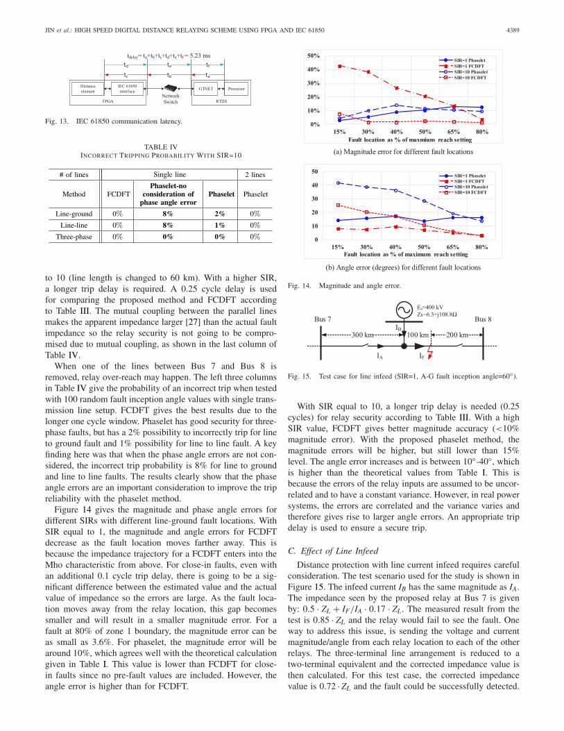
The communication latency (two-way) is about 5.23 mson average, as shown in Figure 13. The response timeperformance matches the standard criteria (specified in IEC61850-5, Type 1A, Class P2/3 messages, 3 ms for one way).
B. Relay Reliability
The security of the proposed relay is tested for faults hap-pening at the remote terminal bus of the line with a SIR equals
JIN et al.: HIGH SPEED DIGITAL DISTANCE RELAYING SCHEME USING FPGA AND IEC 61850 4389
Fig. 13. IEC 61850 communication latency.
TABLE IVINCORRECT TRIPPING PROBABILITY WITH SIR=10
to 10 (line length is changed to 60 km). With a higher SIR,a longer trip delay is required. A 0.25 cycle delay is usedfor comparing the proposed method and FCDFT accordingto Table III. The mutual coupling between the parallel linesmakes the apparent impedance larger [27] than the actual faultimpedance so the relay security is not going to be compro-mised due to mutual coupling, as shown in the last column ofTable IV.
When one of the lines between Bus 7 and Bus 8 isremoved, relay over-reach may happen. The left three columnsin Table IV give the probability of an incorrect trip when testedwith 100 random fault inception angle values with single trans-mission line setup. FCDFT gives the best results due to thelonger one cycle window. Phaselet has good security for three-phase faults, but has a 2% possibility to incorrectly trip for lineto ground fault and 1% possibility for line to line fault. A keyfinding here was that when the phase angle errors are not con-sidered, the incorrect trip probability is 8% for line to groundand line to line faults. The results clearly show that the phaseangle errors are an important consideration to improve the tripreliability with the phaselet method.
Figure 14 gives the magnitude and phase angle errors fordifferent SIRs with different line-ground fault locations. WithSIR equal to 1, the magnitude and angle errors for FCDFTdecrease as the fault location moves farther away. This isbecause the impedance trajectory for a FCDFT enters into theMho characteristic from above. For close-in faults, even withan additional 0.1 cycle trip delay, there is going to be a sig-nificant difference between the estimated value and the actualvalue of impedance so the errors are large. As the fault loca-tion moves away from the relay location, this gap becomessmaller and will result in a smaller magnitude error. For afault at 80% of zone 1 boundary, the magnitude error can beas small as 3.6%. For phaselet, the magnitude error will bearound 10%, which agrees well with the theoretical calculationgiven in Table I. This value is lower than FCDFT for close-in faults since no pre-fault values are included. However, theangle error is higher than for FCDFT.
Fig. 14. Magnitude and angle error.
Fig. 15. Test case for line infeed (SIR=1, A-G fault inception angle=60◦).
With SIR equal to 10, a longer trip delay is needed (0.25cycles) for relay security according to Table III. With a highSIR value, FCDFT gives better magnitude accuracy (<10%magnitude error). With the proposed phaselet method, themagnitude errors will be higher, but still lower than 15%level. The angle error increases and is between 10◦-40◦, whichis higher than the theoretical values from Table I. This isbecause the errors of the relay inputs are assumed to be uncor-related and to have a constant variance. However, in real powersystems, the errors are correlated and the variance varies andtherefore gives rise to larger angle errors. An appropriate tripdelay is used to ensure a secure trip.
C. Effect of Line Infeed
Distance protection with line current infeed requires carefulconsideration. The test scenario used for the study is shown inFigure 15. The infeed current IB has the same magnitude as IA.The impedance seen by the proposed relay at Bus 7 is givenby: 0.5 · ZL + IF/IA · 0.17 · ZL. The measured result from thetest is 0.85 · ZL and the relay would fail to see the fault. Oneway to address this issue, is sending the voltage and currentmagnitude/angle from each relay location to each of the otherrelays. The three-terminal line arrangement is reduced to atwo-terminal equivalent and the corrected impedance value isthen calculated. For this test case, the corrected impedancevalue is 0.72 · ZL and the fault could be successfully detected.
4390 IEEE TRANSACTIONS ON SMART GRID, VOL. 9, NO. 5, SEPTEMBER 2018
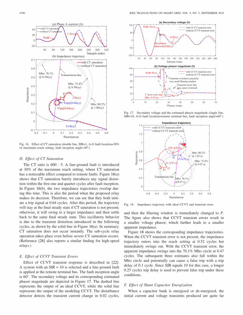
Fig. 16. Effect of CT saturation (double line, SIR=1, A-G fault location=30%of maximum reach setting, fault inception angle=30◦).
D. Effect of CT Saturation
The CT ratio is 600 : 5. A line-ground fault is introducedat 30% of the maximum reach setting, where CT saturationhas a noticeable effect compared to remote faults. Figure 16(a)shows that CT saturation barely introduces any signal distor-tion within the first one and quarter cycles after fault inception.In Figure 16(b), the two impedance trajectories overlap dur-ing this time. This is also the period when the proposed relaymakes its decision. Therefore, we can see that they both initi-ate a trip signal at 0.64 cycles. After this period, the trajectorywill stay at the final steady state if CT saturation is not present;otherwise, it will swing to a larger impedance and then settleback to the same final steady state. This oscillatory behavioris due to the transient distortion introduced in the followingcycles, as shown by the solid line in Figure 16(a). In summary,CT saturation does not occur instantly. The sub-cycle relayoperation takes place even before severe CT saturation occurs.(Reference [28] also reports a similar finding for high-speedrelays.)
E. Effect of CCVT Transient Errors
Effect of CCVT transient response is described in [22].A system with an SIR = 10 is selected and a line-ground faultis applied at the remote terminal bus. The fault inception angleis 60◦. The secondary voltage and its corresponding estimatedphasor magnitude are depicted in Figure 17. The dashed linerepresents the output of an ideal CCVT, while the solid linerepresents the output of the modeling CCVT. The disturbancedetector detects the transient current change in 0.02 cycles,
Fig. 17. Secondary voltage and the estimated phasor magnitude (single line,SIR=10, A-G fault location=remote terminal bus, fault inception angle=60◦).
Fig. 18. Impedance trajectory with ideal CCVT and transient error.
and then the filtering window is immediately changed to P.The figure also shows that CCVT transient errors result ina smaller voltage phasor, which further leads to a smallerapparent impedance.
Figure 18 shows the corresponding impedance trajectories.When the CCVT transient error is not present, the impedancetrajectory enters into the reach setting at 0.52 cycles butimmediately swings out. With the CCVT transient error, theapparent impedance swings into the 70.1% Mho circle at 0.47cycles. The subsequent three estimates also fall within theMho circle and potentially can cause a false trip with a tripdelay of 0.1 cycle. Since SIR equals 10 for this case, a longer0.25 cycles trip delay is used to prevent false trip under theseconditions.
F. Effect of Shunt Capacitor Energization
When a capacitor bank is energized or de-energized, theinitial current and voltage transients produced are quite far

JIN et al.: HIGH SPEED DIGITAL DISTANCE RELAYING SCHEME USING FPGA AND IEC 61850 4391
Fig. 19. System transients (phase A) during a shunt capacitor energization(single line, SIR=1, capacitor size: 102 MVar).
from the relay characteristics and would not cause relay mal-operation. Figure. 19(a) shows the capacitor current at themoment that a capacitor bank is connected to Bus 7. A high-frequency, high-magnitude current flows into the capacitor toattempt to maintain the system voltage. The CT secondary cur-rent is contaminated by a high frequency transient as shownin Figure 19(b). Figure 19(c,d) shows the transient overvolt-ages. The disturbance detector pickups the disturbance butthe transient impedance never enters the Mho characteristicsand therefore the relay would not operate incorrectly for thisscenario.
V. CONCLUSION
The phaselet-based distance relaying is improved by tak-ing into account both magnitude and phase angle errors ofthe voltage and current phasors. A transient monitoring indexis also used to check the phasor estimation error and corre-spondingly adjust the adaptive reach setting. The scheme isimplemented on a FPGA board, which achieves speeds simi-lar to solid-state relays (the processing time for each sampledpacket is 4.04 μs). The proposed sub-cycle method was testedusing hardware-in-the-loop simulations using an RTDS sim-ulator and digital substation communication protocols (IEC61850 SV and GOOSE) to achieve performance comparisonswith current sub-cycle methods in the literature. The exper-imental test shows that the proposed FPGA relay can makesecure trip decision in 0.6∼0.8 cycles. Even with large CCVTtransient errors (SIR equals to 10) and the fault at the remotebus of the line, the proposed relay could make a secure notrip decision.
APPENDIX AMAGNITUDE-PHASE ANGLE ERRORS ANALYSIS
If we assume error ε for the input has a covariance matrix:
E(εεT) = σ 2
ε I, (A.1)
TABLE B1TRANSMISSION LINE PARAMETERS
then according to [29], the covariance matrix of X̂(n) is:
Var(
X̂(n))=σ 2
ε C−1(n)
=σ 2ε
[a11(n) a12(n)
a12(n) a22(n)
], (A.2)
Rewriting Equation 3 in the polar form (X̂ = rejθ ), then thePDF of the phasor magnitude r [16], [17]:
f (r) = 2r
Re
−(r2+r̄2)R I0
(2r̄r
R
), (A.3)
where r̄ is the expectation of r; R is different for each n andR = σ 2
ε [a11(n) + a22(n)]; and I0 is the Bessel function. Thevariance of r is given by:
σ 2r = R + r̄2 − πR
4L2
1/2
(− r̄2
R
), (A.4)
where L1/2 denotes a Laguerre polynomial function. The PDFof the phase angle θ of phasor is given by:
f (θ)=e−g
{1 + √
πξeξ2[1 + erf (ξ)]
}
4πσcσs
√1 − ρ2
× 1
h + ucos2θ + vsin2θ, (A.5)
where erf (·) is the error function. The other variables are:
σc = √a11, σs = √
a22, ρ = a12/(σcσs), (A.6)
h = a11 + a22
4a11a22(1 − ρ2
) , u = a22 − a11
4a11a22(1 − ρ2
) , (A.7)
v = −ρ
2σcσs(1 − ρ2
) , (A.8)
s = X̄cσs − ρX̄sσc
a11σs(1 − ρ2
) , t = X̄sσc − ρX̄cσs
a22σc(1 − ρ2
) , (A.9)
g = X̄2c a22 + X̄2
s a11 − 2ρX̄cX̄sσcσs
2a11a22(1 − ρ2
) , (A.10)
ξ = scosθ + tsinθ
2√
h + ucos2θ + vsin2θ. (A.11)
The postfix (n) in a11(n), a12(n), and a22(n) inEquation (A.6)–(A.11) are not shown but implied for claritypurposes. It is hard to get a closed form solution for equationof σ 2
θ (n) or σθ (n). Instead a numerical solution of σθ (n) isobtained and is given in the third row of Table I.

4392 IEEE TRANSACTIONS ON SMART GRID, VOL. 9, NO. 5, SEPTEMBER 2018
TABLE B2CT PARAMETERS
TABLE B3CCVT PARAMETERS
Fig. B1. CCVT model [22].
APPENDIX BTEST SYSTEM PARAMETERS
See Tables B1, B2, and B3, and Fig. B1.
ACKNOWLEDGMENT
The first author would like to thank Dr. Eli Pajuelo (formerPh.D. student of the University of Saskatchewan) for providingfeedback on the research work.
REFERENCES
[1] E. O. Schweitzer, B. Kasztenny, A. Guzmán, V. Skendzic, andM. V. Mynam, “Speed of line protection—Can we break free ofphasor limitations?” in Proc. 68th Annu. Conf. Protect. Relay Eng.,College Station, TX, USA, 2015, pp. 448–461.
[2] E. A. Udren and M. Sackin, “Relaying features of an integratedmicroprocessor-based substation control and protection system,” in Proc.Develop. Power Syst. Protect., 1980, pp. 97–101.
[3] C.-S. Yu, Y.-S. Huang, and J.-A. Jiang, “A full- and half-cycleDFT-based technique for fault current filtering,” in Proc. IEEEInt. Conf. Ind. Technol. (ICIT), Viña del Mar, Chile, Mar. 2010,pp. 859–864.
[4] T. S. Sidhu, X. Zhang, and V. Balamourougan, “A new half-cycle pha-sor estimation algorithm,” IEEE Trans. Power Del., vol. 20, no. 2,pp. 1299–1305, Apr. 2005.
[5] V. Balamourougan and T. S. Sidhu, “A new filtering technique toeliminate decaying DC and harmonics for power system phasor esti-mation,” in Proc. IEEE Power India Conf., New Delhi, India, 2006,pp. 1–6.
[6] L. Zhan, Y. Liu, and Y. Liu, “A clarke transformation-basedDFT phasor and frequency algorithm for wide frequency range,”IEEE Trans. Smart Grid, vol. PP, no. 99, p. 1, Mar. 22, 2016,doi: 10.1109/TSG.2016.2544947.
[7] H. C. Wood, N. G. Johnson, and M. S. Sachdev, “Kalman fil-tering applied to power system measurements relaying,” IEEETrans. Power App. Syst., vol. PAS-104, no. 12, pp. 3565–3573,Dec. 1985.
[8] A. H. Osman and O. P. Malik, “Transmission line distance protectionbased on wavelet transform,” IEEE Trans. Power Del., vol. 19, no. 2,pp. 515–523, Apr. 2004.
[9] K. Chen, J. Hu, and J. He, “Detection and classification of transmissionline faults based on unsupervised feature learning and convolutionalsparse autoencoder,” IEEE Trans. Smart Grid, vol. PP, no. 99, p. 1,Aug. 10, 2016, doi: 10.1109/TSG.2016.2598881.
[10] M. G. Adamiak, G. E. Alexander, and W. Premerlani, “Advancementsin adaptive algorithms for secure high speed distance protection,” inProc. 23rd Annu. Western Protect. Relay. Conf., Spokane, WA, USA,Oct. 1996, pp. 1–10.
[11] M. G. Adamiak and W. Premerlani, “A new approach to current differ-ential protection for transmission lines,” presented at the Elect. CouncilNew England Protect. Relaying Committee Meeting, Portsmouth, NH,USA, Oct. 1998, pp. 1–16.
[12] Z. Hao et al., “Anti-saturation algorithm in differential protection basedon the phaselet,” in Proc. 5th Int. Conf. Elect. Utility DeregulationRestructuring Power Technol. (DRPT), Changsha, China, Nov. 2015,pp. 1030–1035.
[13] IEC 61850 Communication Networks and Systems in Substations, Int.Electrotech. Comm., Geneva, Switzerland, 2013.
[14] A. G. Phadke and J. S. Thorp, Computer Relaying for Power Systems.Chichester, U.K.: Wiley, 2009.
[15] IEEE Power System Relaying Committee, Application of Fault andDisturbance Recording Devices for Protective System Analysis, IEEEspecial publication 87TH0195-8-PWR, 1987.
[16] K. S. Miller, Complex Stochastic Processes: An Introduction toTheory and Applications. Reading, MA, USA: Addison-Wesley,1974.
[17] K.-H. Ding, M. Rangaswamy, and L. Tsang, “Amplitude andphase distributions for bistatic scattering from pierson-moskowitzsea surfaces,” in Proc. IEEE Radar Conf., Rome, Italy, 2008,pp. 1–6.
[18] ML605 Hardware User Guide, Xilinx, San Jose, CA, USA,Oct. 2012.
[19] RTDS GTNET Network Interface Card Manual, RTDS Technol.,Winnipeg, MB, Canada, Jan. 2014.
[20] S. Jiang, U. D. Annakkage, and A. M. Gole, “A platform for validationof FACTS models,” IEEE Trans. Power Del., vol. 21, no. 1, pp. 484–491,Jan. 2006.
[21] S. H. Horowitz and A. G. Phadke, Power System Relaying. Hoboken,NJ, USA: Wiley, 2013.
[22] E. Pajuelo, G. Ramakrishna, and M. S. Sachdev, “Phasor estimationtechnique to reduce the impact of coupling capacitor voltage transformertransients,” IET Gener. Transm. Distrib., vol. 2, no. 4, pp. 588–599,Jul. 2008.
[23] D90 Plus Line Distance Protection System Instruction Manual, GEMultilin Inc., Markham, ON, Canada, Jul. 2015.
[24] SEL-421-4, -5 Protection and Automation System Data Sheet,Schweitzer Eng. Lab., Pullman, WA, USA, May 2015.
[25] Y. Wang and V. Dinavahi, “Real-time digital multi-function protec-tion system on reconfigurable hardware,” IET Gener. Transm. Distrib.,vol. 10, no. 10, pp. 2295–2305, Jul. 2016.
[26] Y. Wang and V. Dinavahi, “Low-latency distance protective relayon FPGA,” IEEE Trans. Smart Grid, vol. 5, no. 2, pp. 896–905,Mar. 2014.
[27] F. Calero, “Mutual impedance in parallel lines—Protective relaying andfault location considerations,” in Proc. 34th Annu. Western Protect. RelayConf., 2007, pp. 1–15.
[28] J. L. Blackburn and T. J. Domin, Protective Relaying: Principles andApplications. Boca Raton, FL, USA: CRC Press, 2006.
[29] T. K. Moon and W. C. Stirling, Mathematical Methods and Algorithmsfor Signal Processing. Upper Saddle River, NJ, USA: Prentice-Hall,2000.
JIN et al.: HIGH SPEED DIGITAL DISTANCE RELAYING SCHEME USING FPGA AND IEC 61850 4393
Xingxing (Shane) Jin (S’10) received the B.Eng.(Hons.) degree in electrical engineering from theBeijing Institute of Technology, Beijing, China, in2009 and the M.Sc. degree in electrical engineer-ing from the University of Saskatchewan, Saskatoon,SK, Canada, in 2012, where he is currently pur-suing the Ph.D. degree with the Department ofElectrical and Computer Engineering, University ofSaskatchewan. His current research interests are highspeed digital relaying, power system automation,real time simulation of power systems, and parallel
and distributed computing.
Ramakrishna (Rama) Gokaraju (S’88–M’00–SM’15) received the M.Sc. and Ph.D. degreesin electrical and computer engineering from theUniversity of Calgary, Calgary, AB, Canada, in 1996and 2000, respectively. From 1992 to 1994, hewas a Graduate Engineer with Larsen & Toubro-ECC, India, a Research Engineer with RegionalEngineering College, Rourkela, India, and a ProjectAssociate with the Indian Institute of Technology,Kanpur, India. From 1999 to 2002, he wasa Research Scientist with the Alberta Research
Council, and a Staff Software Engineer with IBM Toronto Laboratory. Hejoined the Department of Electrical and Computer Engineering, Universityof Saskatchewan, as an Assistant Professor in 2003, Tenure and AssociateProfessor in 2009, and became a Professor in 2015. His current research worksare high speed digital relaying, wide-area-based power systems protectionand control, renewable energy integrated systems, and real-time simulationapproaches.
Rudi Wierckx received the B.Sc. and M.Sc. degreesin EE from the University of Manitoba, in 1983 and1985, respectively. From 1985 to 1993, he was withthe Manitoba HVDC Research Center, researchingon the development of the real-time digital simula-tor (RTDS). In 1993, he left the Research Center toform RTDS Technologies Inc., and he is currently adirector of that company.
Om Nayak (S’87–M’94–SM’05) received thebachelor’s degree in electrical engineering fromMysore University, India, and the M.Sc. and Ph.D.degrees from the University of Manitoba, Canada,all in power systems. He has extensive hands-onexperience with RTDS and PSCAD simulators as aDeveloper and a User and currently promotes thesetools and services through Nayak Corporation. Hehas several IEEE publications on power systemsmodeling and simulation.