Embed Size (px)
Citation preview
1Introduction to protective relaying
1.1 What is relaying?In order to understand the function of protective relaying systems, one must be familiar withthe nature and the modes of operation of an electric power system. Electric energy is one ofthe fundamental resources of modern industrial society. Electric power is available to the userinstantly, at the correct voltage and frequency, and exactly in the amount that is needed. Thisremarkable performance is achieved through careful planning, design, installation and operation ofa very complex network of generators, transformers, and transmission and distribution lines. To theuser of electricity, the power system appears to be in a steady state: imperturbable, constant andinfinite in capacity. Yet, the power system is subject to constant disturbances created by randomload changes, by faults created by natural causes and sometimes as a result of equipment oroperator failure. In spite of these constant perturbations, the power system maintains its quasi-steady state because of two basic factors: the large size of the power system in relation to the sizeof individual loads or generators, and correct and quick remedial action taken by the protectiverelaying equipment.
Relaying is the branch of electric power engineering concerned with the principles of designand operation of equipment (called ‘relays’ or ‘protective relays’) that detects abnormal powersystem conditions, and initiates corrective action as quickly as possible in order to return thepower system to its normal state. The quickness of response is an essential element of protectiverelaying systems – response times of the order of a few milliseconds are often required. Con-sequently, human intervention in the protection system operation is not possible. The responsemust be automatic, quick and should cause a minimum amount of disruption to the power system.As the principles of protective relaying are developed in this book, the reader will perceive thatthe entire subject is governed by these general requirements: correct diagnosis of trouble, quick-ness of response and minimum disturbance to the power system. To accomplish these goals, wemust examine all possible types of fault or abnormal conditions which may occur in the powersystem. We must analyze the required response to each of these events, and design protectiveequipment which will provide such a response. We must further examine the possibility that pro-tective relaying equipment itself may fail to operate correctly, and provide for a backup protectivefunction. It should be clear that extensive and sophisticated equipment is needed to accomplishthese tasks.
P ower System R elaying, Third Edition. Stanley H . H or owitz and A r un G . Phadke 2008 Resear ch Studies Pr ess L im ited. ISBN: 978-0-470-05712-4

2 Introduction to protective relaying
Control Equipment
Protection Equipment
Power Apparatus
Figure 1.1 Three-layered structure of power systems
1.2 Power system structural considerations1.2.1 Multilayered structure of power systems
A power system is made up of interconnected equipment which can be said to belong to one ofthree layers from the point of view of the functions performed. This is illustrated in Figure 1.1.
At the basic level is the power apparatus which generates, transforms and distributes the electricpower to the loads. Next, there is the layer of control equipment. This equipment helps maintain thepower system at its normal voltage and frequency, generates sufficient power to meet the load andmaintains optimum economy and security in the interconnected network. The control equipmentis organized in a hierarchy of its own, consisting of local and central control functions. Finally,there is the protection equipment layer. The response time of protection functions is generally fasterthan that of the control functions. Protection acts to open and close circuit breakers, thus changingthe structure of the power system, whereas the control functions act continuously to adjust systemvariables, such as the voltages, currents and power flow on the network. Oftentimes, the distinctionbetween a control function and a protection function becomes blurred. This is becoming even moreof a problem with the recent advent of computer-based protection systems in substations. For ourpurposes, we may arbitrarily define all functions which lead to operation of power switches orcircuit breakers to be the tasks of protective relays, while all actions which change the operatingstate (voltages, currents, power flows) of the power system without changing its structure to be thedomain of control functions.
1.2.2 Neutral grounding of power systems
Neutrals of power transformers and generators can be grounded in a variety of ways, dependingupon the needs of the affected portion of the power system. As grounding practices affect faultcurrent levels, they have a direct bearing upon relay system designs. In this section, we will examinethe types of grounding system in use in modern power systems and the reasons for each of thegrounding choices. Influence of grounding practices on relay system design will be considered atappropriate places throughout the remainder of this book.
It is obvious that there is no ground fault current in a truly ungrounded system. This is the mainreason for operating the power system ungrounded. As the vast majority of faults on a power systemare ground faults, service interruptions due to faults on an ungrounded system are greatly reduced.However, as the number of transmission lines connected to the power system grows, the capacitivecoupling of the feeder conductors with ground provides a path to ground, and a ground fault onsuch a system produces a capacitive fault current. This is illustrated in Figure 1.2(a). The couplingcapacitors to ground C0 provide the return path for the fault current. The interphase capacitors13 C1 play no role in this fault. When the size of the capacitance becomes sufficiently large, thecapacitive ground fault current becomes self-sustaining, and does not clear by itself. It then becomes

Power system structural considerations 3
C0 C0 C0
C1
C1
C113
13
13
(a) (b)
Ebg
Ecg
n
ag
Figure 1.2 Neutral grounding impedance. (a) System diagram. (b) Phasor diagram showing neutral shift onground fault
necessary to open the circuit breakers to clear the fault, and the relaying problem becomes oneof detecting such low magnitudes of fault currents. In order to produce a sufficient fault current,a resistance is introduced between the neutral and the ground – inside the box shown by a dottedline in Figure 1.2(a). One of the design considerations in selecting the grounding resistance is thethermal capacity of the resistance to handle a sustained ground fault.
Ungrounded systems produce good service continuity, but are subjected to high overvoltages onthe unfaulted phases when a ground fault occurs. It is clear from the phasor diagram of Figure 1.2(b)that when a ground fault occurs on phase a, the steady-state voltages of phases b and c become√
3 times their normal value. Transient overvoltages become correspondingly higher. This placesadditional stress on the insulation of all connected equipment. As the insulation level of lowervoltage systems is primarily influenced by lightning-induced phenomena, it is possible to acceptthe fault-induced overvoltages as they are lower than the lightning-induced overvoltages. However,as the system voltages increase to higher than about 100 kV, the fault-induced overvoltages beginto assume a critical role in insulation design, especially of power transformers. At high voltages, itis therefore common to use solidly grounded neutrals (more precisely ‘effectively grounded’). Suchsystems have high ground fault currents, and each ground fault must be cleared by circuit breakers.As high-voltage systems are generally heavily interconnected, with several alternative paths to loadcenters, operation of circuit breakers for ground faults does not lead to a reduced service continuity.
In certain heavily meshed systems, particularly at 69 kV and 138 kV, the ground fault currentcould become excessive because of very low zero sequence impedance at some buses. If groundfault current is beyond the capability of the circuit breakers, it becomes necessary to insert aninductance in the neutral in order to limit the ground fault current to a safe value. As the networkThevenin impedance is primarily inductive, a neutral inductance is much more effective (thanresistance) in reducing the fault current. Also, there is no significant power loss in the neutralreactor during ground faults.
In several lower voltage networks, a very effective alternative to ungrounded operation can befound if the capacitive fault current causes ground faults to be self-sustaining. This is the useof a Petersen coil, also known as the ground fault neutralizer (GFN). Consider the symmetricalcomponent representation of a ground fault on a power system, which is grounded through agrounding reactance of Xn (Figure 1.3). If 3Xn is made equal to Xc0 (the zero sequence capacitivereactance of the connected network), the parallel resonant circuit formed by these two elementscreates an open circuit in the fault path, and the ground fault current is once again zero. Nocircuit breaker operation is necessary upon the occurrence of such a fault, and service reliability

4 Introduction to protective relaying
Xl1
Xl1
Xl03Xn
Xc1
Xc1
Xc0
Figure 1.3 Symmetrical component representation for ground fault with grounding reactor
is essentially the same as that of a truly ungrounded system. The overvoltages produced on theunfaulted conductors are comparable to those of ungrounded systems, and consequently GFN use islimited to system voltages below 100 kV. In practice, GFNs must be tuned to the entire connectedzero sequence capacitance on the network, and thus if some lines are out of service, the GFNreactance must be adjusted accordingly. Petersen coils have found much greater use in severalEuropean countries than in the USA.
1.3 Power system bus configurationsThe manner in which the power apparatus is connected together in substations and switchingstations, and the general layout of the power network, has a profound influence on protectiverelaying. It is therefore necessary to review the alternatives, and the underlying reasons for selectinga particular configuration. A radial system is a single-source arrangement with multiple loads, andis generally associated with a distribution system (defined as a system operating at voltages below100 kV) or an industrial complex (Figure 1.4).
Such a system is most economical to build; but from the reliability point of view, the loss of thesingle source will result in the loss of service to all of the users. Opening main line reclosers orother sectionalizing devices for faults on the line sections will disconnect the loads downstream of
From TransmissionNetwork
MainTransformer
Fuse
Switch Switch Switch
Load
Load Load
Figure 1.4 Radial power system
Power system bus configurations 5
Load
Load
Load
Circuit Breakers
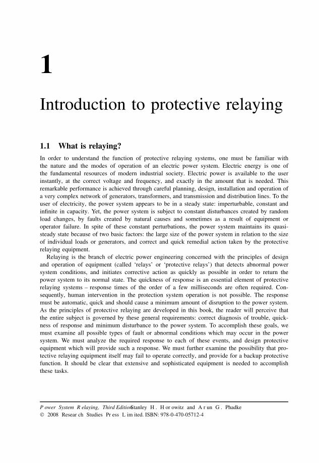
Figure 1.5 Network power system
the switching device. From the protection point of view, a radial system presents a less complexproblem. The fault current can only flow in one direction, i.e. away from the source and towardsthe fault. Since radial systems are generally electrically remote from generators, the fault currentdoes not vary much with changes in generation capacity.
A network has multiple sources and multiple loops between the sources and the loads. Sub-transmission and transmission systems (generally defined as systems operating at voltages of100–200 kV and above) are network systems (Figure 1.5).
In a network, the number of lines and their interconnections provide more flexibility in main-taining service to customers, and the impact of the loss of a single generator or transmission lineon service reliability is minimal. Since sources of power exist on all sides of a fault, fault currentcontributions from each direction must be considered in designing the protection system. In addi-tion, the magnitude of the fault current varies greatly with changes in system configuration andinstalled generation capacity.
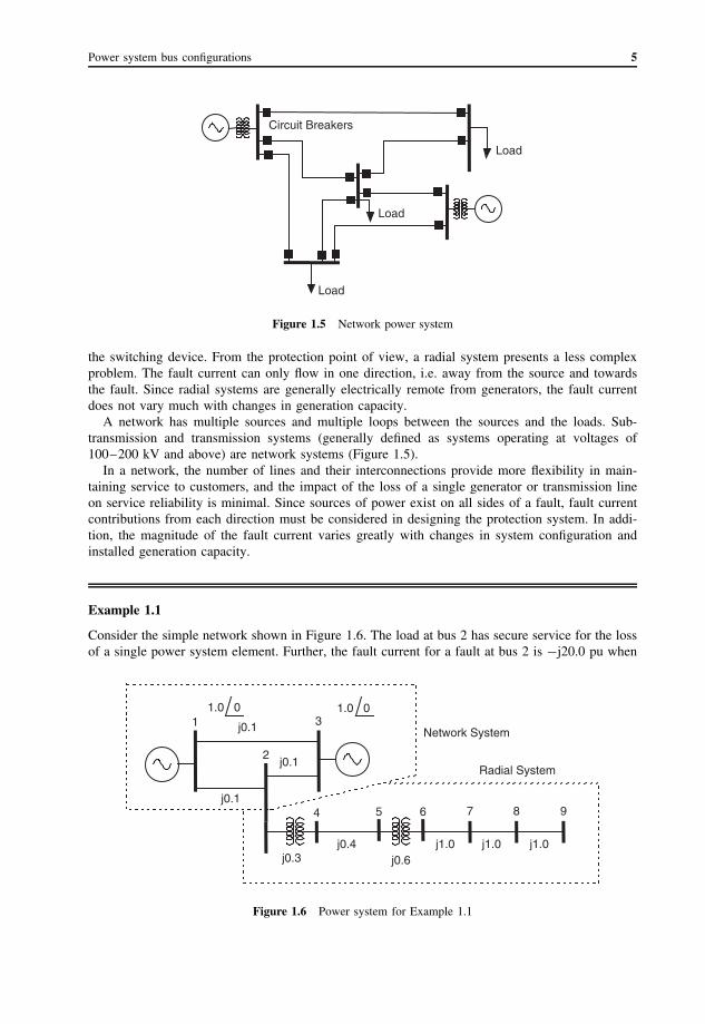
Example 1.1
Consider the simple network shown in Figure 1.6. The load at bus 2 has secure service for the lossof a single power system element. Further, the fault current for a fault at bus 2 is −j20.0 pu when
1 3
2
4 5 6 7 8 9
1.0 01.0 0
j0.1
j0.1
j0.1
j0.3j0.4
j0.6j1.0 j1.0 j1.0
Network System
Radial System
Figure 1.6 Power system for Example 1.1

6 Introduction to protective relaying
all lines are in service. If line 2–3 goes out of service, the fault current changes to −j10.0 pu. Thisis a significant change.
Now consider the distribution feeder with two intervening transformers connected to bus 2. Allthe loads on the feeder will lose their source of power if transformer 2–4 is lost. The fault currentat bus 9 on the distribution feeder with system normal is −j0.23 pu, whereas the same fault whenone of the two generators on the transmission system is lost is −j0.229 pu. This is an insignificantchange. The reason for this of course is that, with the impedances of the intervening transformersand transmission network, the distribution system sees the source as almost a constant impedancesource, regardless of the changes taking place on the transmission network.
Substations are designed for reliability of service and flexibility in operation, and to allow forequipment maintenance with a minimum interruption of service. The most common bus arrange-ments in a substation are (a) single bus, single breaker, (b) two bus, single breaker, (c) two bus,two breakers, (d) ring bus and (e) breaker-and-a-half. These bus arrangements are illustrated inFigure 1.7.
A single-bus, single-breaker arrangement, shown in Figure 1.7(a), is the simplest, and probablythe least costly to build. However, it is also the least flexible. To do maintenance work on the bus,a breaker, or a disconnect switch, de-energizing the associated transmission lines is necessary. Atwo-bus, single-breaker arrangement, shown in Figure 1.7(b), allows the breakers to be maintainedwithout de-energizing the associated line. For system flexibility, and particularly to prevent a busfault from splitting the system too drastically, some of the lines are connected to bus 1 and some tobus 2 (the transfer bus). When maintaining a breaker, all of the lines that are normally connectedto bus 2 are transferred to bus 1, the breaker to be maintained is bypassed by transferring its lineto bus 2 and the bus tie breaker becomes the line breaker. Only one breaker can be maintained ata time. Note that the protective relaying associated with the buses and the line whose breaker is
(a)
(b)
(c)
(d)
# 1 # 1
# 2
# 1# 2
(e)
# 1
# 2
Figure 1.7 Substation bus arrangements: (a) single bus, single breaker; (b) two bus, one breaker; (c) two bus,two breaker; (d) ring bus; (e) breaker-and-a-half
The nature of relaying 7
being maintained must also be reconnected to accommodate this new configuration. This will becovered in greater detail as we discuss the specific protection schemes.
A two-bus, two-breaker arrangement is shown in Figure 1.7(c). This allows any bus or breakerto be removed from service, and the lines can be kept in service through the companion bus orbreaker. A line fault requires two breakers to trip to clear a fault. A bus fault must trip all ofthe breakers on the faulted bus, but does not affect the other bus or any of the lines. This stationarrangement provides the greatest flexibility for system maintenance and operation; however, this isat a considerable expense: the total number of breakers in a station equals twice the number of thelines. A ring bus arrangement shown in Figure 1.7(d) achieves similar flexibility while the ring isintact. When one breaker is being maintained, the ring is broken, and the remaining bus arrangementis no longer as flexible. Finally, the breaker-and-a-half scheme, shown in Figure 1.7(e), is mostcommonly used in most extra high voltage (EHV) transmission substations. It provides for the sameflexibility as the two-bus, two-breaker arrangement at the cost of just one-and-a-half breakers perline on an average. This scheme also allows for future expansions in an orderly fashion.∗
The impact of system and bus configurations on relaying practices will become clear in thechapters that follow.
1.4 The nature of relayingWe will now discuss certain attributes of relays which are inherent to the process of relaying, andcan be discussed without reference to a particular relay. The function of protective relaying is topromptly remove from service any element of the power system that starts to operate in an abnormalmanner. In general, relays do not prevent damage to equipment: they operate after some detectabledamage has already occurred. Their purpose is to limit, to the extent possible, further damage toequipment, to minimize danger to people, to reduce stress on other equipment and, above all, toremove the faulted equipment from the power system as quickly as possible so that the integrityand stability of the remaining system is maintained. The control aspect of relaying systems alsohelps return the power system to an acceptable configuration as soon as possible so that service tocustomers can be restored.
1.4.1 Reliability, dependability and security
Reliability is generally understood to measure the degree of certainty that a piece of equipmentwill perform as intended. Relays, in contrast with most other equipment, have two alternative waysin which they can be unreliable: they may fail to operate when they are expected to, or theymay operate when they are not expected to. This leads to a two-pronged definition of reliabilityof relaying systems: a reliable relaying system must be dependable and secure.1 Dependability isdefined as the measure of the certainty that the relays will operate correctly for all the faults forwhich they are designed to operate. Security is defined as the measure of the certainty that therelays will not operate incorrectly for any fault.
Most protection systems are designed for high dependability. In other words, a fault is alwayscleared by some relay. As a relaying system becomes dependable, its tendency to become less
∗ The breaker-and-a-half bus configuration is the natural outgrowth of operating practices that developed as systems matured. Evenin developing systems, the need to keep generating units in service was recognized as essential and it was common practice toconnect the unit to the system through two circuit breakers. Depending on the particular bus arrangement, the use of two breakersincreased the availability of the unit despite line or bus faults or circuit breaker maintenance. Lines and transformers, however,were connected to the system through one circuit breaker per element. With one unit and several lines or transformers per station,there was a clear economic advantage to this arrangement. When the number of units in a station increased, the number of breakersincreased twice as fast: 1 unit and 2 lines required 4 breakers, 2 units and 2 lines required 6 breakers, etc. It is attractive torearrange the bus design so that the lines and transformers shared the unit breakers. This gave the same maintenance advantage tothe lines, and when the number of units exceeded the number of other elements, reduced the number of breakers required.

8 Introduction to protective relaying
secure increases. Thus, in present-day relaying system designs, there is a bias towards makingthem more dependable at the expense of some degree of security. Consequently, a majority ofrelay system mis-operations are found to be the result of unwanted trips caused by insecurerelay operations. This design philosophy correctly reflects the fact that a power system providesmany alternative paths for power to flow from generators to loads. Loss of a power systemelement due to an unnecessary trip is therefore less objectionable than the presence of a sus-tained fault. This philosophy is no longer appropriate when the number of alternatives for powertransfer is limited, as in a radial power system, or in a power system in an emergency operat-ing state.
Example 1.2
Consider the fault F on the transmission line shown in Figure 1.8. In normal operation, this faultshould be cleared by the two relays R1 and R2 through the circuit breakers B1 and B2. If R2
does not operate for this fault, it has become unreliable through a loss of dependability. If relayR5 operates through breaker B5 for the same fault, and before breaker B2 clears the fault, it hasbecome unreliable through a loss of security. Although we have designated the relays as singleentities, in reality they are likely to be collections of several relays making up the total protectionsystem at each location. Thus, although a single relay belonging to a protection system may losesecurity, its effect is to render the complete relaying system insecure, and hence unreliable.
B1 B2
R1 R2
R4
R5
F
B3
B4
B5
R3
Figure 1.8 Reliability of protection system
1.4.2 Selectivity of relays and zones of protection
The property of security of relays, that is, the requirement that they not operate for faults forwhich they are not designed to operate, is defined in terms of regions of a power system – calledzones of protection – for which a given relay or protective system is responsible. The relay will beconsidered to be secure if it responds only to faults within its zone of protection. Relays usuallyhave inputs from several current transformers (CTs), and the zone of protection is bounded bythese CTs. The CTs provide a window through which the associated relays ‘see’ the power systeminside the zone of protection. While the CTs provide the ability to detect a fault inside the zoneof protection, the circuit breakers (CBs) provide the ability to isolate the fault by disconnecting allof the power equipment inside the zone. Thus, a zone boundary is usually defined by a CT and aCB. When the CT is part of the CB, it becomes a natural zone boundary. When the CT is not anintegral part of the CB, special attention must be paid to the fault detection and fault interruptionlogic. The CT still defines the zone of protection, but communication channels must be used to

The nature of relaying 9
implement the tripping function from appropriate remote locations where the CBs may be located.We will return to this point later in section 1.5 where CBs are discussed.
In order to cover all power equipment by protection systems, the zones of protection must meetthe following requirements.
• All power system elements must be encompassed by at least one zone. Good relaying practiceis to be sure that the more important elements are included in at least two zones.
• Zones of protection must overlap to prevent any system element from being unprotected. With-out such an overlap, the boundary between two nonoverlapping zones may go unprotected. Theregion of overlap must be finite but small, so that the likelihood of a fault occurring inside theregion of overlap is minimized. Such faults will cause the protection belonging to both zonesto operate, thus removing a larger segment of the power system from service.
A zone of protection may be closed or open. When the zone is closed, all power apparatusentering the zone is monitored at the entry points of the zone. Such a zone of protection is alsoknown as ‘differential’, ‘unit’ or ‘absolutely selective’. Conversely, if the zone of protection is notunambiguously defined by the CTs, i.e. the limit of the zone varies with the fault current, the zone issaid to be ‘non-unit’, ‘unrestricted’ or ‘relatively selective’. There is a certain degree of uncertaintyabout the location of the boundary of an open zone of protection. Generally, the nonpilot protectionof transmission lines employs open zones of protection.
Example 1.3
Consider the fault at F1 in Figure 1.9. This fault lies in a closed zone, and will cause circuit breakersB1 and B2 to trip. The fault at F2, being inside the overlap between the zones of protection ofthe transmission line and the bus, will cause circuit breakers B1, B2, B3 and B4 to trip, althoughopening B3 and B4 is unnecessary. Both of these zones of protection are closed zones.
B1
B2
B3
B4
B5 B6
F1
F 2F3
Figure 1.9 Closed and open zones of protection
Now consider the fault at F3. This fault lies in two open zones. The fault should cause circuitbreaker B6 to trip. B5 is the backup breaker for this fault, and will trip if for some reason B6 failsto clear the fault.
1.4.3 Relay speed
It is, of course, desirable to remove a fault from the power system as quickly as possible. However,the relay must make its decision based upon voltage and current waveforms which are severely

10 Introduction to protective relaying
distorted due to transient phenomena which must follow the occurrence of a fault. The relay mustseparate the meaningful and significant information contained in these waveforms upon which asecure relaying decision must be based. These considerations demand that the relay take a certainamount time to arrive at a decision with the necessary degree of certainty. The relationship betweenthe relay response time and its degree of certainty is an inverse one,2 and this inverse-time operatingcharacteristic of relays is one of the most basic properties of all protection systems.
Although the operating time of relays often varies between wide limits, relays are generallyclassified by their speed of operation as follows.3
1. Instantaneous. These relays operate as soon as a secure decision is made. No intentional timedelay is introduced to slow down the relay response.†
2. Time delay. An intentional time delay is inserted between the relay decision time and theinitiation of the trip action.‡
3. High speed. A relay that operates in less than a specified time. The specified time in presentpractice is 50 milliseconds (3 cycles on a 60 Hz system).
4. Ultra high speed. This term is not included in the Relay Standards but is commonly consideredto be operation in 4 milliseconds or less.
1.4.4 Primary and backup protection4,5
A protection system may fail to operate and, as a result, fail to clear a fault. It is thus essentialthat provision be made to clear the fault by some alternative protection system or systems. Thesealternative protection system(s) are referred to as duplicate, backup or breaker-failure protectionsystems. The main protection system for a given zone of protection is called the primary protectionsystem. It operates in the fastest time possible and removes the least amount of equipment fromservice. On EHV systems it is common to use duplicate primary protection systems in case anelement in one primary protection chain may fail to operate. This duplication is therefore intendedto cover the failure of the relays themselves. One may use relays from a different manufacturer, orrelays based upon a different principle of operation, so that some inadequacy in the design of oneof the primary relays is not repeated in the duplicate system. The operating times of the primaryand the duplicate systems are the same.
It is not always practical to duplicate every element of the protection chain – on high-voltage andEHV systems the transducers or the circuit breakers are very expensive, and the cost of duplicateequipment may not be justified. On lower voltage systems, even the relays themselves may not beduplicated. In such situations, only backup relaying is used. Backup relays are generally slowerthan the primary relays and remove more system elements than may be necessary to clear a fault.Backup relaying may be installed locally, i.e. in the same substation as the primary protection, orremotely. Remote backup relays are completely independent of the relays, transducers, batteriesand circuit breakers of the protection system they are backing up. There are no common failuresthat can affect both sets of relays. However, complex system configurations may significantly affectthe ability of remote backup relays to ‘see’ all the faults for which backup is desired. In addition,remote backup relays may remove more loads in the system than can be allowed. Local backuprelaying does not suffer from these deficiencies, but it does use common elements such as the
† There is no implication relative to the speed of operation of an instantaneous relay. It is a characteristic of its design. A plunger-type overcurrent relay will operate in 1–3 cycles depending on the operating current relative to its pickup setting. A 125 V DChinged auxiliary relay, operating on a 125 V DC circuit, will operate in 3–6 cycles, whereas a 48 V DC tripping relay operatingon the same circuit will operate in 1 cycle. All are classified as instantaneous.‡ The inserted time delay can be achieved by an R–C circuit, an induction disc, a dashpot or other electrical or mechanical means.A short-time induction disc relay used for bus protection will operate in 3–5 cycles, a long-time induction disc relay used for motorprotection will operate in several seconds and bellows or geared timing relays used in control circuits can operate in minutes.
The nature of relaying 11
transducers, batteries and circuit breakers, and can thus fail to operate for the same reasons as theprimary protection.
Breaker failure relays are a subset of local backup relaying that is provided specifically to covera failure of the circuit breaker. This can be accomplished in a variety of ways. The most common,and simplest, breaker failure relay system consists of a separate timer that is energized wheneverthe breaker trip coil is energized and is de-energized when the fault current through the breakerdisappears. If the fault current persists for longer than the timer setting, a trip signal is given to alllocal and remote breakers that are required to clear the fault. Occasionally a separate set of relaysis installed to provide this breaker failure protection, in which case it uses independent transducers,and batteries. (Also see Chapter 12 (Section 12.4).)
These ideas are illustrated by the following example, and will be further examined when specificrelaying systems are considered in detail later.
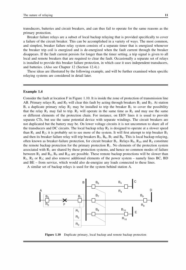
Example 1.4
Consider the fault at location F in Figure 1.10. It is inside the zone of protection of transmission lineAB. Primary relays R1 and R5 will clear this fault by acting through breakers B1 and B5. At stationB, a duplicate primary relay R2 may be installed to trip the breaker B1 to cover the possibilitythat the relay R1 may fail to trip. R2 will operate in the same time as R1 and may use the sameor different elements of the protection chain. For instance, on EHV lines it is usual to provideseparate CTs, but use the same potential device with separate windings. The circuit breakers arenot duplicated but the battery may be. On lower voltage circuits it is not uncommon to share all ofthe transducers and DC circuits. The local backup relay R3 is designed to operate at a slower speedthan R1 and R2; it is probably set to see more of the system. It will first attempt to trip breaker B1
and then its breaker failure relay will trip breakers B5, B6, B7 and B8. This is local backup relaying,often known as breaker-failure protection, for circuit breaker B1. Relays R9, R10 and R4 constitutethe remote backup protection for the primary protection R1. No elements of the protection systemassociated with R1 are shared by these protection systems, and hence no common modes of failurebetween R1 and R4, R9 and R10 are possible. These remote backup protections will be slower thanR1, R2 or R3; and also remove additional elements of the power system – namely lines BC, BDand BE – from service, which would also de-energize any loads connected to these lines.
A similar set of backup relays is used for the system behind station A.
A
B C
D
E
F
B1
B4
B5
B6
B7
B8
B9
B10R1
R2
R3
R4
R5 R9
R10
Figure 1.10 Duplicate primary, local backup and remote backup protection
12 Introduction to protective relaying
1.4.5 Single- and three-phase tripping and reclosing
The prevailing practice in the USA is to trip all three phases of the faulted power system elementfor all types of fault. In several European and Asian countries, it is a common practice to trip onlythe faulted phase for a phase-to-ground fault, and to trip all three phases for all multiphase faults ontransmission lines. These differences in the tripping practice are the result of several fundamentaldifferences in the design and operation of power systems, as discussed in section 1.6.
As a large proportion of faults on a power system are of a temporary nature, the power systemcan be returned to its prefault state if the tripped circuit breakers are reclosed as soon as possible.Reclosing can be manual. That is, it is initiated by an operator working from the switching deviceitself, from a control panel in the substation control house or from a remote system control centerthrough a supervisory control and data acquisition (SCADA) system. Clearly, manual reclosing istoo slow for the purpose of restoring the power system to its prefault state when the system isin danger of becoming unstable. Automatic reclosing of circuit breakers is initiated by dedicatedrelays for each switching device, or it may be controlled from a substation or central reclosingcomputer. All reclosing operations should be supervised (i.e. controlled) by appropriate interlocksto prevent an unsafe, damaging or undesirable reclosing operation. Some of the common interlocksfor reclosing are the following.
1. Voltage check. Used when good operating practice demands that a certain piece of equipment beenergized from a specific side. For example, it may be desirable to always energize a transformerfrom its high-voltage side. Thus if a reclosing operation is likely to energize that transformer,it would be well to check that the circuit breaker on the low-voltage side is closed only if thetransformer is already energized.
2. Synchronizing check. This check may be used when the reclosing operation is likely to ener-gize a piece of equipment from both sides. In such a case, it may be desirable to check thatthe two sources which would be connected by the reclosing breaker are in synchronism andapproximately in phase with each other. If the two systems are already in synchronism, it wouldbe sufficient to check that the phase angle difference between the two sources is within certainspecified limits. If the two systems are likely to be unsynchronized, and the closing of the circuitbreaker is going to synchronize the two systems, it is necessary to monitor the phasors of thevoltages on the two sides of the reclosing circuit breaker and close the breaker as the phasorsapproach each other.
3. Equipment check. This check is to ensure that some piece of equipment is not energizedinadvertently.
These interlocks can be used either in the manual or in the automatic mode. It is the practiceof some utilities, however, not to inhibit the manual reclose operation of circuit breakers, on theassumption that the operator will make the necessary checks before reclosing the circuit breaker.In extreme situations, sometimes the only way to restore a power system is through operatorintervention, and automatic interlocks may prevent or delay the restoration operation. On the otherhand, if left to the operator during manual operation, there is the possibility that the operator maynot make the necessary checks before reclosing.
Automatic reclosing can be high speed, or it may be delayed. The term high speed generallyimplies reclosing in times shorter than a second. Many utilities may initiate high-speed reclosing forsome types of fault (such as ground faults), and not for others. Delayed reclosing usually operates inseveral seconds or even in minutes. The timing for the delayed reclosing is determined by specificconditions for which the delay is introduced.

Elements of a protection system 13
1.5 Elements of a protection systemAlthough, in common usage, a protection system may mean only the relays, the actual protectionsystem consists of many other subsystems which contribute to the detection and removal of faults.As shown in Figure 1.11, the major subsystems of the protection system are the transducers, relays,battery and circuit breakers. The transducers, i.e. the current and voltage transformers, constitute amajor component of the protection system, and are considered in detail in Chapter 3. Relays are thelogic elements which initiate the tripping and closing operations, and we will, of course, discussrelays and their performance in the rest of this book.
1.5.1 Battery and DC supply
Since the primary function of a protection system is to remove a fault, the ability to trip a circuitbreaker through a relay must not be compromised during a fault, when the AC voltage availablein the substation may not be of sufficient magnitude. For example, a close-in three-phase faultcan result in zero AC voltage at the substation AC outlets. Tripping power, as well as the powerrequired by the relays, cannot therefore be obtained from the AC system, and is usually providedby the station battery.
The battery is permanently connected through a charger to the station AC service, and normally,during steady-state conditions, it floats on the charger. The charger is of a sufficient volt–amperecapacity to provide all steady-state loads powered by the battery. Usually, the battery is alsorated to maintain adequate DC power for 8–12 hours following a station blackout. Although thebattery is probably the most reliable piece of equipment in a station, in EHV stations it is notuncommon to have duplicate batteries, each connected to its own charger and complement ofrelays. Electromechanical relays are known to produce severe transients on the battery leads duringoperation, which may cause mis-operation of other sensitive relays in the substation, or may evendamage them. It is therefore common practice, insofar as practical, to separate electromechanicaland solid-state equipment by connecting them to different batteries.
1.5.2 Circuit breakers
It would take too much space to describe various circuit breaker designs and their operating prin-ciples here. Indeed, several excellent references do just that.6,7 Instead, we will describe a fewsalient features about circuit breakers, which are particularly significant from the point of view ofrelaying.
Knowledge of circuit breaker operation and performance is essential to an understanding ofprotective relaying. It is the coordinated action of both that results in successful fault clearing. The
Transducer
Relay
Battery
Breaker
Figure 1.11 Elements of a protection system
14 Introduction to protective relaying
circuit breaker isolates the fault by interrupting the current at or near a current zero. At the presenttime, an EHV circuit breaker can interrupt fault currents of the order of 105 A at system voltages upto 800 kV. It can do this as quickly as the first current zero after the initiation of a fault, althoughit more often interrupts at the second or third current zero. As the circuit breaker contacts moveto interrupt the fault current, there is a race between the establishment of the dielectric strength ofthe interrupting medium and the rate at which the recovery voltage reappears across the breakercontacts. If the recovery voltage wins the race, the arc re-ignites, and the breaker must wait for thenext current zero when the contacts are farther apart.
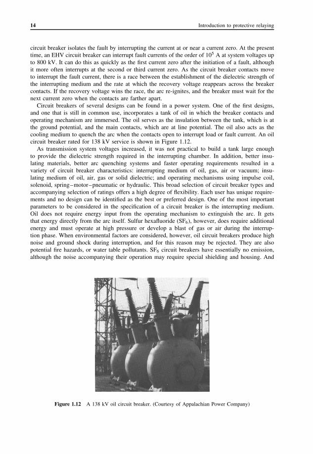
Circuit breakers of several designs can be found in a power system. One of the first designs,and one that is still in common use, incorporates a tank of oil in which the breaker contacts andoperating mechanism are immersed. The oil serves as the insulation between the tank, which is atthe ground potential, and the main contacts, which are at line potential. The oil also acts as thecooling medium to quench the arc when the contacts open to interrupt load or fault current. An oilcircuit breaker rated for 138 kV service is shown in Figure 1.12.
As transmission system voltages increased, it was not practical to build a tank large enoughto provide the dielectric strength required in the interrupting chamber. In addition, better insu-lating materials, better arc quenching systems and faster operating requirements resulted in avariety of circuit breaker characteristics: interrupting medium of oil, gas, air or vacuum; insu-lating medium of oil, air, gas or solid dielectric; and operating mechanisms using impulse coil,solenoid, spring–motor–pneumatic or hydraulic. This broad selection of circuit breaker types andaccompanying selection of ratings offers a high degree of flexibility. Each user has unique require-ments and no design can be identified as the best or preferred design. One of the most importantparameters to be considered in the specification of a circuit breaker is the interrupting medium.Oil does not require energy input from the operating mechanism to extinguish the arc. It getsthat energy directly from the arc itself. Sulfur hexafluoride (SF6), however, does require additionalenergy and must operate at high pressure or develop a blast of gas or air during the interrup-tion phase. When environmental factors are considered, however, oil circuit breakers produce highnoise and ground shock during interruption, and for this reason may be rejected. They are alsopotential fire hazards, or water table pollutants. SF6 circuit breakers have essentially no emission,although the noise accompanying their operation may require special shielding and housing. And
Figure 1.12 A 138 kV oil circuit breaker. (Courtesy of Appalachian Power Company)

Elements of a protection system 15
Figure 1.13 A 345 kV SF6 circuit breaker. (Courtesy of Appalachian Power Company)
as with all engineering decisions, the cost of the circuit breaker must be an important considera-tion. At present, oil-filled circuit breakers are the least expensive, and may be preferred if they aretechnically feasible, but this may change in the future. A typical SF6 circuit breaker is shown inFigure 1.13.
An important design change in circuit breakers with a significant impact on protection systemswas the introduction of the ‘live-tank’ design.8 By placing the contact enclosure at the same potentialas the contacts themselves, the need for the insulation between the two was eliminated. However theearlier ‘dead-tank’ (Figure 1.12) designs incorporated CTs in the bushing pocket of the tank, therebyproviding CTs on both sides of the contacts. This arrangement provided a very nice mechanism forproviding overlapping zones of protection on the two sides of the circuit breakers. In the live-tankdesign, since the entire equipment is at line potential, it is not possible to incorporate CTs whichhave their secondary windings essentially at the ground potential. It then becomes necessary todesign the CTs with their own insulating system, as separate free-standing devices, a design whichis quite expensive. With free-standing CTs, it is no longer economical to provide CTs on both
(a) (b)
(c)linebus
F1 F2 F3 F4
bus
B1
F1 F2
line busbus
Figure 1.14 Zone overlap with different types of CTs and circuit breakers

16 Introduction to protective relaying
Figure 1.15 Live-tank air-blast circuit breaker and a current transformer for 800 kV. (Courtesy of AppalachianPower Company)
sides of a circuit breaker, and one must make do with only one CT on one side of the breaker.Of course, a free-standing CT has multiple secondaries, and protection zone overlap is achievedby using secondary windings on opposite sides of the zones of protection. This is illustrated inFigure 1.14(a). A live-tank air-blast circuit breaker and a free-standing CT rated at 800 kV areshown in Figure 1.15. The location of the primary winding and the protective assignments of thesecondary winding of the CTs have a very significant implication for the protection being provided.This is illustrated in the following example.
Example 1.5
Consider the dead-tank circuit breaker shown in Figure 1.14(b). The bushing CTs are on eitherside of the breaker and the secondaries are connected to the bus and line protection so that theyoverlap at the breaker. For a fault at F1 both protective systems will operate. The bus differentialrelays will trip B1 and all other breakers on the bus. This will clear the fault. The line protectionwill similarly trip breaker B1; and the corresponding relays at the remote station will also trip theirassociated breakers. This is unnecessary, but unavoidable. If there are tapped loads on the line,they will be de-energized until the breakers reclose. For a fault at F2, again both protective systemswill operate. For this fault, tripping the other bus breakers is not necessary to clear the fault, buttripping the two ends of the line is necessary.
Now consider the live-tank design shown in Figure 1.14(c). For a fault at F1, only the busprotection sees the fault and correctly trips B1 and all the other bus breakers to clear the fault. Fora fault at F2, however, tripping the bus breakers does not clear the fault, since it is still energizedfrom the remote end, and the line relays do not operate. This is a blind spot in this configuaration.Column protection will cover this area. For a fault at F3 and F4, the line relays will operate andthe fault will be cleared from both ends. The fault at F3 again results in unnecessary tripping ofthe bus breakers.
International practices 17
1.6 International practicesAlthough the fundamental protective and relay operating concepts are similar throughout the world,there are very significant differences in their implementation. These differences arise through differ-ent traditions, operating philosophies, experiences and national standards. Electric power utilities inmany countries are organs of the national government. In such cases, the specific relaying schemesemployed by these utilities may reflect the national interest. For example, their preference may befor relays manufactured inside their respective countries. In some developing countries, the choiceof relays may be influenced by the availability of low-cost hard-currency loans, or a transfer-of-technology agreement with the prospective vendor of the protective equipment. The evolutionarystage of the power system itself may have an influence on the protection philosophy. Thus moremature power systems may opt for a more dependable protection system at the expense of somedegradation of its (protection system’s) security. A developing power network has fewer alternativepaths for power transfer between the load and generation, and a highly secure protection systemmay be the desired objective. Long transmission lines are quite common in countries with largeareas, e.g. the USA or Russia. Many European and Asian countries have relatively short transmis-sion lines, and, since the protection practice for long lines is significantly different from that forshort lines, this may be reflected in the established relaying philosophy.
As mentioned in section 1.4, reclosing practices also vary considerably among different countries.When one phase of a three-phase system is opened in response to a single phase fault, the voltageand current in the two healthy phases tend to maintain the fault arc after the faulted phase is de-energized. Depending on the length of the line, system operating voltage and load, compensatingshunt reactors may be necessary to extinguish this ‘secondary’ arc.9 Where the transmission linesare short, such secondary arcs are not a problem, and no compensating reactors are needed. Thusin countries with short transmission lines, single-phase tripping and reclosing may be a soundand viable operating strategy. In contrast, when transmission lines are long, the added cost ofcompensation may dictate that three-phase tripping and reclosing be used for all faults. The lossof synchronizing power flow created by three-phase tripping is partially mitigated by the use ofhigh-speed reclosing. Also, use is made of high-speed relaying (three cycles or less) to reduce theimpact of three-phase tripping and reclosing. Of course, there are exceptional situations which maydictate a practice that is out of the ordinary in a given country. Thus, in the USA, where high-speedtripping with three-phase tripping and reclosing is the general trend, exception may be made whena single transmission line is used to connect a remote generator to the power system. Three-phasetripping of such a line for a ground fault may cause the loss of the generator for too many faults,and single-phase tripping and reclosing may be the desirable alternative.
An important factor in the application of specific relay schemes is associated with the configura-tion of the lines and substations. Multiple circuit towers as found throughout Europe have differentfault histories than single circuit lines, and therefore have different protection system needs. Thesame is true for double-bus, transfer bus or other breaker bypassing arrangements. In the USA,EHV stations are almost exclusively breaker-and-a-half or ring bus configurations. This provisionto do maintenance work on a breaker significantly affects the corresponding relaying schemes. Thephilosophy of installing several complete relay systems also affects the testing capabilities of allrelays. In the USA, it is not the common practice to remove more than one phase or zone relayat a time for calibration or maintenance. In other countries this may not be considered to be asimportant, and the testing facilities built in the relays may not be as selective.
The use of turnkey contracts to design and install complete substations also differs considerablybetween countries, being more prevalent in many European, South American and certain Asiancountries than in North America. This practice leads to a manufacturer or consulting engineeringconcern taking total project responsibility, as opposed to the North American practice where theutilities themselves serve as the general contractor. In the latter case, the effect is to reduce thevariety of protection schemes and relay types in use.

18 Introduction to protective relaying
1.7 Summary
In this chapter, we have examined some of the fundamentals of protective relaying philosophy.The concept of reliability and its two components, dependability and security, have been intro-duced. Selectivity has been illustrated by closed and open zones of protection and local versusremote backup. The speed of relay operation has been defined. Three-phase tripping, the prevailingpractice in the USA, has been compared to the more prevalent European practice of single-phasetripping. We have discussed various reclosing and interlocking practices, and the underlying reasonsfor a given choice. We have also given a brief account of various types of circuit breaker, and theirimpact on the protection system design.
Problems1.1 Write a computer program to calculate the three-phase fault current for a fault at F in
Figure 1.16, with the network normal, and with one line at a time removed from service.The positive sequence impedance data are given in the accompanying table. Use the com-monly made assumption that all prefault resistance values are (1.0 + j0.0) pu, and neglect allresistance values. Calculate the contribution to the fault flowing through the circuit breakerB1, and the voltage at that bus. For each calculated case, consider the two possibilities:circuit breaker B2 closed or open. The latter is known as the ‘stub-end’ fault.
1 2
3
4
5
67
B1 B2
F
Figure 1.16 Problem 1.1
System data for Figure 1.16
From To Positive sequenceimpedance
1 2 0.0 + j0.12 6 0.05 + j0.152 5 0.04 + j0.22 4 0.01 + j0.13 5 0.015 + j0.153 6 0.01 + j0.194 5 0.01 + j0.194 6 0.03 + j0.16 7 0.0 + j0.08

Summary 19
1.2 Using the usual assumptions about the positive and negative sequence impedances of thenetwork elements, what are the currents at breaker B1 for b–c fault for each of the faults inProblem 1.1? What is the voltage between phases b and c for each case?
1.3 For the radial power system shown in Figure 1.17, calculate the line-to-ground fault currentflowing in each of the circuit breakers for faults at each of the buses. The system data aregiven in the accompanying table. Also determine the corresponding faulted phase voltage,assuming that the generator is ideal, with a terminal voltage of 1.0 pu.
1 2 3 4 5 6
B1 B2 B3 B4 B5
Figure 1.17 Problem 1.3
System data for Figure 1.17
From To Positive sequence Zero sequenceimpedance impedance
1 2 0.01 + j0.05 0.02 + j0.132 3 0.003 + j0.04 0.01 + j0.163 4 0.008 + j0.04 0.04 + j0.154 5 0.01 + j0.05 0.03 + j0.155 6 0.003 + j0.02 0.01 + j0.06
1.4 In a single loop distribution system shown in Figure 1.18, determine the fault currents flowingin circuit breakers B1, B2 and B3 for a b–c fault at F. What are the corresponding phase-to-phase voltages at those locations? Consider the generator to be of infinite short-circuitcapacity, and with a voltage of 1.0 pu. Consider two alternatives: (a) both transformers T1
and T2 in service and (b) one of the two transformers out of service. The system data aregiven in the accompanying table.
1 2 3 4
5
67
T1
T2
B1FB2 B3
Figure 1.18 Problem 1.4

20 Introduction to protective relaying
System data for Figure 1.18
From To Positive sequenceimpedance
1 2 0.0 + j0.01(T1)
0.0 + j0.01(T2)
2 3 0.0 + j0.083 4 0.02 + j0.054 5 0.01 + j0.035 6 0.0 + j0.066 7 0.01 + j0.092 7 0.01 + j0.09
1.5 In the double-bus arrangement shown in Figure 1.19, circuit breaker B1 must be taken out ofservice for repair. Starting with all equipment in service, make a list of operations requiredto take the circuit breaker out of service, and to return it to service. Repeat for all the busarrangements shown in Figure 1.7. Remember that disconnect switches are generally notdesigned to break or make load current.
B1 B2 B3 B4
1
2
L1 L2
S11
S12
S21
S22
S31
S32
S41
S42
Figure 1.19 Problem 1.5
1.6 Consider the various bus arrangements shown in Figure 1.7. Assume that each of the devicetypes, bus, disconnect switch, circuit breaker and transmission line, may develop a fault andis removed from service. Prepare a table listing (single) faults which would cause loss of loadconnected to the remote end of one of the transmission lines in each of those configurations.What conclusions can you draw from such a table?
1.7 For the system shown in Figure 1.20, the fault at F produces these differing responses atvarious times: (a) R1 B1 and R2 B2 operate; (b) R1 B1, R2, R3 B3 and R4 B4 operate;(c) R1 B1, R2 B2 and R5 B5 operate; (d) R1 B1, R5 B5 and R6 B6 operate. Analyze eachof these responses for fault F and discuss the possible sequence of events that may haveled to these operations. Classify each response as being correct, incorrect, appropriate or

Summary 21
inappropriate. Note that ‘correct–incorrect’ classification refers to relay operation, whereas‘appropriate–inappropriate’ classification refers to the desirability of that particular responsefrom the point of view of the power system. Also determine whether there was a loss ofdependability or a loss of security in each of these cases.
R1 R2
R3
R4
R5
R6
B1 B2
B3
B4
B5
B6
Figure 1.20 Problem 1.7
1.8 In the systems shown in Figure 1.21(a) and (b), it is desired to achieve overlap between thezones of protection for the bus and the transmission line. Show how this may be achievedthrough the connection of CTs to the appropriate protection systems.
Bus
Line
Dead TankBreaker
(a) (b)
Live TankBreaker
Bus
Line
Figure 1.21 Problem 1.8
1.9 In the part of the network shown in Figure 1.22, the minimum and maximum operating timesfor each relay are 0.8 and 2.0 cycles (of the fundamental power system frequency), and eachcircuit breaker has minimum and maximum operating times of 2.0 and 5.0 cycles. Assumethat a safety margin of 3.0 cycles between any primary protection and backup protection isdesirable. P2 is the local backup for P1, and P3 is the remote backup. Draw a timing diagramto indicate the various times at which the associated relays and breakers must operate toprovide a secure (coordinated) backup coverage for fault F.
P1 P2 P3F
Figure 1.22 Problem 1.9
22 Introduction to protective relaying
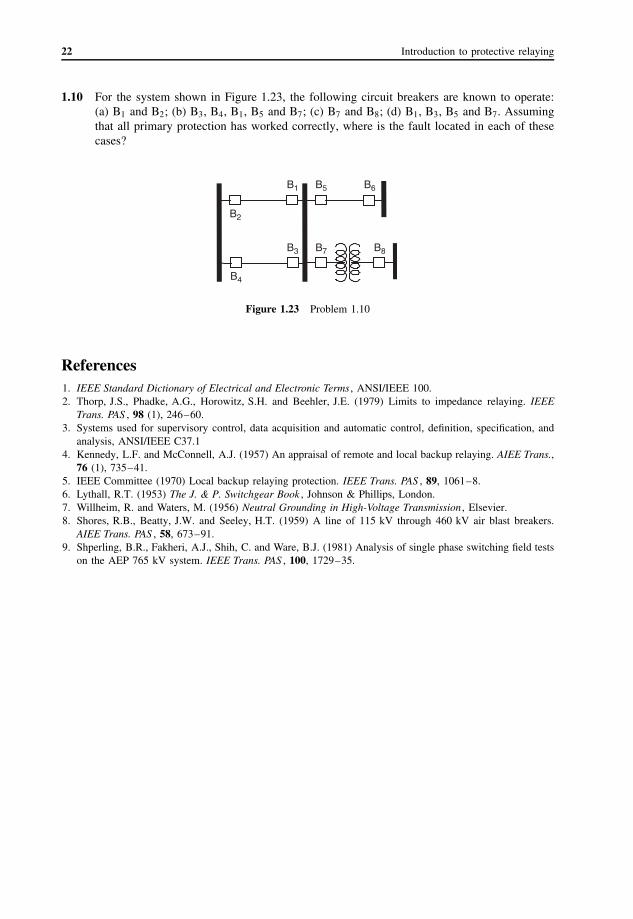
1.10 For the system shown in Figure 1.23, the following circuit breakers are known to operate:(a) B1 and B2; (b) B3, B4, B1, B5 and B7; (c) B7 and B8; (d) B1, B3, B5 and B7. Assumingthat all primary protection has worked correctly, where is the fault located in each of thesecases?
B1
B2
B3
B4
B5 B6
B7 B8
Figure 1.23 Problem 1.10
References1. IEEE Standard Dictionary of Electrical and Electronic Terms , ANSI/IEEE 100.2. Thorp, J.S., Phadke, A.G., Horowitz, S.H. and Beehler, J.E. (1979) Limits to impedance relaying. IEEE
Trans. PAS , 98 (1), 246–60.3. Systems used for supervisory control, data acquisition and automatic control, definition, specification, and
analysis, ANSI/IEEE C37.14. Kennedy, L.F. and McConnell, A.J. (1957) An appraisal of remote and local backup relaying. AIEE Trans.,
76 (1), 735–41.5. IEEE Committee (1970) Local backup relaying protection. IEEE Trans. PAS , 89, 1061–8.6. Lythall, R.T. (1953) The J. & P. Switchgear Book , Johnson & Phillips, London.7. Willheim, R. and Waters, M. (1956) Neutral Grounding in High-Voltage Transmission , Elsevier.8. Shores, R.B., Beatty, J.W. and Seeley, H.T. (1959) A line of 115 kV through 460 kV air blast breakers.
AIEE Trans. PAS , 58, 673–91.9. Shperling, B.R., Fakheri, A.J., Shih, C. and Ware, B.J. (1981) Analysis of single phase switching field tests
on the AEP 765 kV system. IEEE Trans. PAS , 100, 1729–35.