Embed Size (px)
Citation preview
Leadership in fusible circuit protection
SERIEESSBussmann seriesHigh speed fuse application guide

Eaton is the leading source of fusible
circuit protection solutions in the global
marketplace. Eaton’s Bussmann series
products are approved for use around
the world and meet agency requirements
and international standards: IEC, VDE,
DIN, UL, CSA, BS and others.
The headquarters for Eaton’s
Bussmann series product line is
located in Burton-on-the-Wolds,
Leicestershire (UK) and is part
of Eaton’s Industrial Control and
Protection EMEA division.
Eaton manufactures over 50,000
Bussmann series part numbers,
covering extensive fusible circuit
protection solutions for a wide
range of applications: residential,
industrial, motor protection, power
conversion and distribution.
Eaton has been a leading expo-
nent in the design, development
and manufacture of fuse links
and their associated accessories
for more than 100 years and has
supplied fuse links to more than
90 countries worldwide.
Eaton's team of specialist
Engineers and Field Applications
Engineers plays a leading role
in international standardisation
of fuse links offering compre-
hensive advice on selection and
applications.
With a continual commitment to
meet our customers' needs with
innovative high quality products
with ISO 9001 'approval systems',
Eaton is the supplier of choice for
circuit protection solutions.
2 EATON High speed fuse application guide

Contents
Introduction 4Background . . . . . . . . . . . . . . . . . . . . . . . . . . . . . . . . . . . . . . . . . . . . . . . . 4
Typical fuse construction . . . . . . . . . . . . . . . . . . . . . . . . . . . . . . . . . . . . . 4
Fuse Operation . . . . . . . . . . . . . . . . . . . . . . . . . . . . . . . . . . . . . . . . . . . . . 5
Protection requirements for high speed fuse links 6How high speed fuses are different than other fuses . . . . . . . . . . . . . . 6
Characteristics required / provided . . . . . . . . . . . . . . . . . . . . . . . . . . . . . 6
Ambient temperatures . . . . . . . . . . . . . . . . . . . . . . . . . . . . . . . . . . . . . . . 7
Local ambient temperature . . . . . . . . . . . . . . . . . . . . . . . . . . . . . . . . . . . 7
Forced cooling . . . . . . . . . . . . . . . . . . . . . . . . . . . . . . . . . . . . . . . . . . . . . 7
Mean, peak and RMS currents . . . . . . . . . . . . . . . . . . . . . . . . . . . . . . . . 7
Time-current characteristics . . . . . . . . . . . . . . . . . . . . . . . . . . . . . . . . . . . 7
Surges . . . . . . . . . . . . . . . . . . . . . . . . . . . . . . . . . . . . . . . . . . . . . . . . . . . . 7
Coordination with semiconductor characteristics 8Short-circuit performance . . . . . . . . . . . . . . . . . . . . . . . . . . . . . . . . . . . . 8
I²t ratings . . . . . . . . . . . . . . . . . . . . . . . . . . . . . . . . . . . . . . . . . . . . . . . . . 8
Peak fuse currents . . . . . . . . . . . . . . . . . . . . . . . . . . . . . . . . . . . . . . . . . . 8
Arc voltage . . . . . . . . . . . . . . . . . . . . . . . . . . . . . . . . . . . . . . . . . . . . . . . . 8
Conductor size . . . . . . . . . . . . . . . . . . . . . . . . . . . . . . . . . . . . . . . . . . . . . 8
Package protection . . . . . . . . . . . . . . . . . . . . . . . . . . . . . . . . . . . . . . . . . . 8
The high speed fuse data sheet 9The time-current curve . . . . . . . . . . . . . . . . . . . . . . . . . . . . . . . . . . . . . . . 9
The AA-curve . . . . . . . . . . . . . . . . . . . . . . . . . . . . . . . . . . . . . . . . . . . . . 10
Clearing integral information . . . . . . . . . . . . . . . . . . . . . . . . . . . . . . . . . 10
The I²t curve . . . . . . . . . . . . . . . . . . . . . . . . . . . . . . . . . . . . . . . . . . . . . . 10
Cut-off current curve . . . . . . . . . . . . . . . . . . . . . . . . . . . . . . . . . . . . . . . 11
The arc voltage curve . . . . . . . . . . . . . . . . . . . . . . . . . . . . . . . . . . . . . . . 11
Watt loss correction curve . . . . . . . . . . . . . . . . . . . . . . . . . . . . . . . . . . . 11
Temperature conditions . . . . . . . . . . . . . . . . . . . . . . . . . . . . . . . . . . . . . 11
Rated voltage dimensioning 12Voltage rating . . . . . . . . . . . . . . . . . . . . . . . . . . . . . . . . . . . . . . . . . . . . . 12
IEC voltage ratings . . . . . . . . . . . . . . . . . . . . . . . . . . . . . . . . . . . . . . . . . 12
North American voltage rating . . . . . . . . . . . . . . . . . . . . . . . . . . . . . . . 12
Simple rated voltage dimensioning . . . . . . . . . . . . . . . . . . . . . . . . . . . . 12
Frequency dependency . . . . . . . . . . . . . . . . . . . . . . . . . . . . . . . . . . . . . . 12
Extended rated voltage dimensioning . . . . . . . . . . . . . . . . . . . . . . . . . . 12
Possible AC/ DC combinations . . . . . . . . . . . . . . . . . . . . . . . . . . . . . . . 12
AC fuses in DC circuits . . . . . . . . . . . . . . . . . . . . . . . . . . . . . . . . . . . . . . 13
Fuses under oscillating DC . . . . . . . . . . . . . . . . . . . . . . . . . . . . . . . . . . . 13
Fuses in series . . . . . . . . . . . . . . . . . . . . . . . . . . . . . . . . . . . . . . . . . . . . 13
Rated current dimensioning 14Part 1 — Basic selection . . . . . . . . . . . . . . . . . . . . . . . . . . . . . . . . . . . . 14
Part 2 — Influence of overloads . . . . . . . . . . . . . . . . . . . . . . . . . . . . . . 15
Part 3 — Cyclic loading . . . . . . . . . . . . . . . . . . . . . . . . . . . . . . . . . . . . . 16
Application areas — general 18RMS Currents in common bridge arrangements . . . . . . . . . . . . . . . . . . 18
Typical rectifier circuits 19Protection by fuses 20
Internal and external faults . . . . . . . . . . . . . . . . . . . . . . . . . . . . . . . . . . 20
Protection from internal faults . . . . . . . . . . . . . . . . . . . . . . . . . . . . . . . . 20
Protection from an external fault . . . . . . . . . . . . . . . . . . . . . . . . . . . . . . 20
Service interruption upon device failure . . . . . . . . . . . . . . . . . . . . . . . . 20
Non-interrupted service upon device failure . . . . . . . . . . . . . . . . . . . . . 20
Fuses under DC conditions 21DC fed systems . . . . . . . . . . . . . . . . . . . . . . . . . . . . . . . . . . . . . . . . . . . . 21
Battery as a load . . . . . . . . . . . . . . . . . . . . . . . . . . . . . . . . . . . . . . . . . . 21
Battery as only source . . . . . . . . . . . . . . . . . . . . . . . . . . . . . . . . . . . . . . 22
DC application of Eaton's Bussmann seriessquare body AC fuses 23
Calculation example . . . . . . . . . . . . . . . . . . . . . . . . . . . . . . . . . . . . . . . . 24
Photovoltaic systems 25Fuses selection for protecting regenerative DC-drives 26
Conclusion on the rectifier mode . . . . . . . . . . . . . . . . . . . . . . . . . . . . . . 26
Conclusion on the regenerative mode . . . . . . . . . . . . . . . . . . . . . . . . . . 27
Summary of Voltage Selection for Regenerative Drives: (4Q-Service) . 27
Protecting inverters 28Voltage selection . . . . . . . . . . . . . . . . . . . . . . . . . . . . . . . . . . . . . . . . . . 28
Current selection . . . . . . . . . . . . . . . . . . . . . . . . . . . . . . . . . . . . . . . . . . 28
I²t Selection . . . . . . . . . . . . . . . . . . . . . . . . . . . . . . . . . . . . . . . . . . . . . . 28
IGBT as switching device . . . . . . . . . . . . . . . . . . . . . . . . . . . . . . . . . . . . 28
IGBT inverter . . . . . . . . . . . . . . . . . . . . . . . . . . . . . . . . . . . . . . . . . . . . . . 29
Protection of drive circuits . . . . . . . . . . . . . . . . . . . . . . . . . . . . . . . . . . . 29
Bi-polar power transistors and darlingtons . . . . . . . . . . . . . . . . . . . . . . 29
Worked examples 30Example 1 — DC thyristor drive . . . . . . . . . . . . . . . . . . . . . . . . . . . . . . 30
Example 2 —
DC supply with redundant diodes . . . . . . . . . . . . . . . . . . . . . . . . . . . . . 30
Example 3 —
Regenerative drive application . . . . . . . . . . . . . . . . . . . . . . . . . . . . . . . 31
Appendix 1International Standards and Eaton's Bussmann seriesproduct range 32
In Europe . . . . . . . . . . . . . . . . . . . . . . . . . . . . . . . . . . . . . . . . . . . . . . . . . 32
In the United States . . . . . . . . . . . . . . . . . . . . . . . . . . . . . . . . . . . . . . . . 32
Eaton's Bussmann series product range . . . . . . . . . . . . . . . . . . . . . . . . 32
European standard . . . . . . . . . . . . . . . . . . . . . . . . . . . . . . . . . . . . . . . . . 32
Blade type fuses . . . . . . . . . . . . . . . . . . . . . . . . . . . . . . . . . . . . . . . . . . . 32
Flush-end contact type . . . . . . . . . . . . . . . . . . . . . . . . . . . . . . . . . . . . . . 32
British Standard — BS88 . . . . . . . . . . . . . . . . . . . . . . . . . . . . . . . . . . . 33
US Style — North American blade and flush-end style . . . . . . . . . . . . 33
Cylindrical fuses . . . . . . . . . . . . . . . . . . . . . . . . . . . . . . . . . . . . . . . . . . . 33
Appendix 2Fuse reference system 34
The following describes the Eaton's Bussmann series
reference system in detail — style by style. . . . . . . . . . . . . . . . . . . . . 34
Reference system for European high speed fuses . . . . . . . . . . . . . . . . 34
Reference system for BS88 High speed fuse links . . . . . . . . . . . . . . . . 35
Reference System for US High Speed Fuses . . . . . . . . . . . . . . . . . . . . . 36
Special fuses - Types SF and XL . . . . . . . . . . . . . . . . . . . . . . . . . . . . . . 37
Appendix 3Installation, service, maintenance, environmentaland storage issues 38
Tightening torque and contact pressure . . . . . . . . . . . . . . . . . . . . . . . . 38
Fuses with flush end contacts . . . . . . . . . . . . . . . . . . . . . . . . . . . . . . . . 38
Special flush-end types . . . . . . . . . . . . . . . . . . . . . . . . . . . . . . . . . . . . . 38
Fuses with contact knives . . . . . . . . . . . . . . . . . . . . . . . . . . . . . . . . . . . 38
DIN 43653 — on busbars . . . . . . . . . . . . . . . . . . . . . . . . . . . . . . . . . . . 38
DIN 43653 — in fuse holders . . . . . . . . . . . . . . . . . . . . . . . . . . . . . . . . 39
DIN 43620 . . . . . . . . . . . . . . . . . . . . . . . . . . . . . . . . . . . . . . . . . . . . . . . . 39
Press pack fuses . . . . . . . . . . . . . . . . . . . . . . . . . . . . . . . . . . . . . . . . . . . 39
Mounting alignment . . . . . . . . . . . . . . . . . . . . . . . . . . . . . . . . . . . . . . . . 40
Surface material . . . . . . . . . . . . . . . . . . . . . . . . . . . . . . . . . . . . . . . . . . . 40
Tin-plated contacts . . . . . . . . . . . . . . . . . . . . . . . . . . . . . . . . . . . . . . . . . 40
Vibration and shock resistance . . . . . . . . . . . . . . . . . . . . . . . . . . . . . . . 40
Service and maintenance . . . . . . . . . . . . . . . . . . . . . . . . . . . . . . . . . . . . 40
Environmental issues . . . . . . . . . . . . . . . . . . . . . . . . . . . . . . . . . . . . . . . 40
Storage . . . . . . . . . . . . . . . . . . . . . . . . . . . . . . . . . . . . . . . . . . . . . . . . . . 40
Appendix 4Glossary 41
3EATON High speed fuse application guide

Introduction
With local sales and technical assistance in all regions of the world, Eaton is able to provide industry with optimum fuse solutions. In addition, when needed and practical, Eaton performs tests at our Paul G. Gubany Center for High Power Technology at Eaton in St. Louis, where test currents up to 720 V a.c. three-phase / 200 kA, 720 V a.c. single phase / 200 kA and 1000 V d.c. / 100 kA can be obtained.
This guide’s objective is to provide engineers easy access to Eaton data for high speed fuses. It also provides detailed information on the Eaton's Bussmann series high speed fuse reference system. The various physical standards are covered with examples of applications along the considerations to cover in selecting rated voltage, rated current and similar main data for protecting power semiconductors. Guidelines for fuse mounting is covered, with explanations on how to read and understand Eaton data sheets and drawings.
This document is not a complete guide for protecting all applications of power semiconductors. The market is simply too complex to make such a document, and, in some cases, the actual fuse selection will require detailed technical discussions between the engineers specifying the equipment and Eaton Application Engineering.
However, the data presented here will be of help in daily work and provide the reader with the basic knowledge of our products and their application.
Background
The fuse has been around since the earliest days of electric telegraphs and then later for the protecting power distribution and other circuits.
The fuse has undergone considerable evolution since those early days. The modern High Breaking Capacity (HBC)/high interrupting rating fuse provides an economical and reliable protection against overcurrent faults in modern electrical systems.
The basic fuse operation simple — excess current passing through specially designed fuse elements causes them to melt to isolate the faulty circuit. Fuses have now developed for many applica-tions with current ratings of only a few milliamps to many thousands of amps, and for use in circuits of a few volts to those for 72kV distribution systems.
The most common use for fuses is in electrical distribution systems where they are placed throughout the system to give protection to cables, transformers, switches, control gear and equipment. Along with different current and voltage ratings, fuse operating char-acteristics are changed to meet specific application areas and unique protection requirements.
The definitions on how fuses especially designed for a certain purpose (fuse class) are included in the Glossary.
Modern fuses are made in many shapes and sizes, but all have the same key features. Although all fuse components influence the total fuse performance, the key part is the fuse element. This will be made from a high conductivity material and that is shaped to produce a number of reduced sections commonly referred to as ’necks’ or ’weak spots.’ It is mainly these reduced sections that will control the fuse’s operating char-acteristics. The element is surrounded with an arc-quenching material, usually graded quartz, that “quench” the arc that forms when the reduced sections melt. It is this function that gives the fuse its current limiting ability.
To contain the quartz is an insulating container usually referred to as the fuse body, made of ceramic or engineering plastic. Finally, to connect the fuse element to the circuit it protects there are end connectors, usually of copper. The other component parts of a fuse vary depending on the type of fuse and the manufacturing methods used.
Gasket
Innerend cap
Ceramicbody
Endconnector
Outerend cap
Element
Endconnector
Glass fiber body
Element
End plate
Ceramic body
Element
End fitting
Screw
The history of Eaton's Bussmann series high speed fuse links discussed
in this guide is long and proud. Since the first international acquisition
in 1984, Eaton has expanded in order to service customers with fuses in
all recognized world standards. Based on three different global standards
and with ISO 9000 manufacturing locations worldwide, Eaton provides
industry with globally accepted high speed fuses and accessories for
protecting power semiconductors.
Typical fuse construction
4 EATON High speed fuse application guide

Fuse Operation
The fuse operation depends primarily on the balance between the rate of heat generated within the element and the rate of heat dissipated to external connections and surrounding atmosphere. For current values up to the continuous maximum rating of the fuse design ensures that all the heat generated is dissipated without exceeding the pre-set maximum tempera-tures of the element or other components. Under conditions of sustained overloads, the rate of heat generated is greater than that dissipated and causes the fuse element temperature to rise. The tempera-ture rise at the reduced sections of the elements (“necks” or “weak spots”) will be higher than elsewhere, and once the temperature reaches the element material melting point it will “break,” thus isolating the circuit. The time taken for the element to melt and break decreases with increas-ing current levels.
The current level that causes the fuse to operate in a time of 4 hours is called the minimum fusing current, and the ratio of minimum fusing current to the rated current is called the fusing factor of that fuse. Under heavy overloading, or short-circuit conditions, there is little time for heat dissipation from the element and the temperature at the restrictions reach the melting point almost instantaneously. Under these conditions, the element will commence melting well before the prospective fault current (AC) has reached its first major peak. The time taken from
the initiation of the fault to the element melting is called the pre-arcing time. This interruption of a heavy current results in an arc being formed at each restriction with the arc offering a higher resistance. The arc’s heat vaporizes the element material; the vapor fusing with the quartz to form a non-conductive rock like substance called fulgurite. The arc also tends to burn the element away from the restriction to increase the arc length and further increase the arc resistance. The cumulative effect is the extinction of the arc in a very short time and the final isolation of the circuit. Under such heavy overload and short-circuit conditions the total time taken from initiation of fault to the final clearance of the circuit is very short, typically in a few milliseconds. The current through the fuse has been limited. Such current limita-tion is obtained at current levels as low as 4 times the normal continuous rating of the fuse.
The time taken from the appearance of the arc to its final extinction is called the arcing time. The sum of the pre-arcing and arcing time is the total operating time. During the pre-arcing and the arcing times a certain amount of energy will be released depend-ing on the magnitude of the current. The terms pre-arcing energy and arcing energy are similarly used to correspond to the times. Such energy will be proportional to the integral of the square of the current multiplied by the time the current flows, and often abbreviated as I2t; where I is the RMS value of the current and t is the time in seconds for which the current flows.
For high values of current, the melting time is too short for heat to be lost from the reduced section (is adiabatic) and pre-arcing I2t is therefore a constant. The arcing I2t, however, also depends on circuit condi-tions. The published data quoted is based on the worst possible conditions and is measured from actual tests. These will be detailed later.
The arc causes a voltage across the fuse and is termed the arc voltage. Although this depends on the element design, it is also governed by circuit conditions. This arc voltage will exceed the system voltage. The design of the element allows the magnitude of the arc voltage to be controlled to known limits. The use of a number of reduced sections in the element, in series, assists in controlling the arcing process and also the resultant arc voltage.
Thus, a well-designed fuse not only limits the the prospective current level, but also ensures the fault is cleared in an extremely short time and the energy released to protected equipment is considerably smaller than that available.
Pre-arcing time Arcing time
Possibleunrestrictedfault current
Peak currentstart of arcing
Start of fault
Actual current
5EATON High speed fuse application guide

Protection requirements for high speed fuse links
In industrial applications, fault currents of many thousands of amps occur if an electrical fault develops somewhere in the circuit. Semiconductor devices can withstand these high currents only for extremely short periods of time. High current levels cause two harmful effects on semiconductor devices. First, non-uniform current distribution at the p-n junction(s) of the silicon creates abnormal current densities and causes damage. Second, a thermal effect is created that’s proportional to the product I², (RMS value of current)², × t, (I²t - time for which the current flows).
As a result, the overcurrent protective device must:
A. Safely interrupt very high prospec-tive fault currents in extremely short times
B. Limit the current allowed to pass through to the device
C. Limit the thermal energy (I²t) let-through to the device during fault interruption
Unfortunately, ultra fast interruption of large currents creates high overvoltages. If a silicon rectifier is subjected to this, it will fail due to breakdown phenomena. The protective device selected must, therefore, also limit the overvoltage during fault interruption.
So far, consideration has mainly been given to protection against high fault currents. In order to obtain maximum utilization of the device, coupled with complete reliability, the protective device selected must also:
D. Not require maintenance
E. Not operate at normal rated current or during normal transient overload conditions
F. Operate in a predetermined manner when abnormal conditions occur
The only overcurrent protective device with all these qualities at an economical cost is the modern high speed fuse. Normal fuses (i.e., those complying with IEC 60269-2) are designed primarily to protect industrial equipment, and possess all the qualities mentioned above, but not to the degree required for protecting semiconductor devices.
For these reasons, special fuse types have been developed to protect semiconductor devices. They are characterized by their high operating speed and are referred to as semiconductor or, more accurately, high speed fuses.
The term semiconductor fuse is mislead-ing as there is no semiconductor material involved in their construction.
How high speed fuses are different than other fuses
High speed fuses have been developed to minimize the I²t, peak current let-through and arc voltage. To ensure rapid element melting, the high speed fuse restrictions (necks) have a different design than a simi-larly rated industrial fuse and are typically operated at higher temperatures.
High speed fuses typically operate with higher heat dissipation requirements than other fuse types because of their higher element temperatures and they are often in smaller packages. To help dissipate heat, the body or barrel materials used are often a higher grade.
High speed fuses are primarily for protect-ing semiconductors from short-circuit devices where high operating tempera-tures often restrict using low melting point alloys to assist with low overcurrent operation. The result is that high speed fuses often have more limited capability to protect against these low overcurrent conditions.
Many high speed fuses are physically different from standard fuse types and require additional mounting arrangements with the benefit that it helps prevent installing an incorrect fuses.
Characteristics required / provided
For fuse protection of semiconductors, a number of device and fuse parameters need to be considered. Of the parameters there are a number of influencing factors associated with each. The manner in which these are presented and interpreted will be shown in what follows. These parameters and associated factors need to be applied and considered with due reference to the specific requirements of the circuits and application. Some of these factors are covered in the sections on voltage dimensioning, current dimensioning and applications.
Silicon-based semiconductor devices (diodes, thyristors, Gate turn-off thyris-
tors [GTO], transistors and isolated gate bipolar transistors [IGBT]) have found
an increasing number of applications in power and control circuit rectification,
inversion and regulation. Their advantage is the ability to handle considerable
power in a very small physical size. Due to their relatively small mass, their
capacity to withstand overloads and overvoltages is limited.
6 EATON High speed fuse application guide

Table 1. Factors to consider in fuse selection
* The protection of transistors is more complex and will be described in the section on IGBT protection
Ambient temperatures
Fuses for protecting semiconductors may have to be derated for ambience temperatures in excess of 21°C. Ratings at other temperatures are shown on derating graphs.
Local ambient temperature
Poor fuse mounting, enclosed fuses and proximity to other apparatus and fuses can give rise to high local ambient temperature. The maximum fuse rating in these cases should be determined for each applica-tion using the local ambient temperature as described in the section on current dimensioning.
Forced cooling
To achieve maximum ratings in many installations, diodes or thyristors are force cooled in an air stream. Fuses can be similarly uprated if placed in an air stream. Air velocities above 5m/s do not produce any substantial increase in the ratings. For further information see the sections on current dimensioning and data sheets.
Mean, peak and RMS currents
Care must be taken in coordinating fuse currents with the circuit currents. Fuse currents are usually quoted in Root-Mean Square (RMS) values while diodes and thyristors in quoted in terms of mean values.
Time-current characteristics
These are derived using the same test arrangement as the temperature rise tests, with the fuse at ambient temperature before each test. For standard fuses, the nominal melting times are plotted against RMS current values down to melting times of 10ms. For high speed fuses, the virtual melting time is used and shown down to 0.1ms.
Surges
Effects of cyclic loading or transient surges can be considered by coordinating the effective RMS current values and durations of the surges with the time-current char-acteristics. The following points should be remembered when using these published characteristics:
1. The characteristics are subject to a 5 percent tolerance on current.
2. For times below one second, circuit constants and instants of fault occur-rence affect the time-current charac-teristics. Minimum nominal times are published relating to symmetrical RMS currents.
3. Pre-loading at maximum current rat-ing reduces the actual melting time. Cyclic conditions are detailed in the section on current dimensioning.
Parameter
Factors affecting parameter Data provided
Fuse Diode or thyristor * Fuse Diode or thyristor *
Steady state RMS current Ambient, attachment, proximity of other apparatus and other fuses, cooling employed
Ambient, type of circuit, parallel operation, cooling employed
Maximum rated current under specified conditions, factors for ambient, up-rating for forced cool-ing, conductor size
Comprehensive curves (mean cur-rents generally quoted)
Watts dissipated for steady state
As for current As for current Maximum quoted for specified conditions
Comprehensive data
Overload capability Pre-loading, cyclic loading surges, manufacturing tolerances
Pre-loading, cyclic loading surges Nominal time/current curves for initially cold fuses – calculation guidelines for duty cycles
Overload curves, also transient thermal impedances
Interrupting capacity AC or DC voltage/short-circuit levels
Interrupting rating
I²t ratings Pre-loading; total I²t dependent on: circuit impedance, applied voltage, point of initiation of short-circuit
Pre-loading fault duration For initially cold fuses: total I2t curves for worst case conditions, pre-arcing I²t constant Fuse clear-ing time
Half cycle value or values for dif-ferent pulse duration
Peak let-through current Pre-loading; fault current (voltage second order effect)
Pre-loading fault duration Curves for worst conditions for initially cold fuse-links
Peak current for fusing
Arc voltage Peak value dependent on: applied voltage, circuit impedance, point of initiation of short-circuit
P.I.V. voltage ratings (non- repeti-tive)
Maximum peak arc voltages plot-ted against applied voltage
P.I.V. voltage rating quoted (non-repetitive)
7EATON High speed fuse application guide

Coordination with semiconductor characteristics
Short-circuit performance
The short-circuit zone of operation is usually taken as operating times less than 10 milliseconds (½ cycle on 50Hz supply in AC circuits). It is in this region that high speed fuses are current limiting. Since the majority of the applications are fed from AC sources, the performance data for fuses are usually given for AC operations. Where applicable, prospective symmetrical RMS currents are used.
I²t ratings
The pre-arcing (melting) I²t tends to a minimum value when the fuse is subjected to high currents with this value being shown on the data sheet. The arcing I²t varies with applied voltage, fault level, power factor and the point on wave of the initiation of the short-circuit. The total I²t figures shown are for the worst of these conditions. The majority of semiconductor manufacturers give I²t ratings for their power semiconductors that should not be exceeded during fusing at all times below 10ms. These are statistically the lowest values for when the device has been pre-loaded.
For effective device protection, the total I²t of the fuse must be less than the I²t capability of the device.
Peak fuse currents
Under short-circuit conditions, high speed fuses are inherently current limiting (the peak current through the fuse is less than the prospective peak current). The “Cut-off” characteristic, (the peak fuse current against symmetrical prospective RMS current) are shown in the data sheets. Peak fuse currents should be coordinated with diode or thyristor data in addition to I²t.
Arc voltage
The arc voltage produced during fuse operation varies with the applied system voltage. Curves showing variations of arc voltage with system voltage are included in the data sheets. Care must be taken in coordinating the peak arc voltage of the fuse with the peak transient voltage capa-bility of the device.
Conductor size
The RMS current ratings assigned to Eaton's Bussmann series fuse links are based upon standard sized conductors at each end of the fuse during rating tests. These will be based on between 1 and 1.6 A/mm². Using smaller or larger conductors will affect the current rating of the fuse.
Package protection
Some semiconductor devices are extremely sensitive to overcurrents and overvoltages for which fuses may not operate fast enough to prevent some or even complete damage to the device. High speed fuses are still employed in such cases to minimize overcurrent events when the silicon or small connection wires are melting. Without these fuses, the packaging surrounding the silicon may open, with the potential to cause damage to equipment or injury to persons.
8 EATON High speed fuse application guide

The high speed fuse data sheet
The time-current curve
The time-current curve, also called the melting curve, enables the user to find vital information in the selection and dimensioning phase. See Fig.1.
The axes are the prospective short-circuit current (Ip) in amp symmetrical RMS and virtual Pre-Arcing time (tv) in seconds, as specified in IEC 60269. The melting time of a given fuse can be found based on a known short-circuit current value. In practice, virtual times longer than approximately 100ms are equivalent to real time.
Using Ip and tv direct from the fuse time-current curve permits calculating its melting integral in A²s (Ip² x tv) for the actual value of prospective current. The following method shows two examples (I1 and I2) with guidelines to determine the effect on a fuse from an overload or short-circuit:
• First, the actual overload/short-circuit current must be known, either in the form of a curve — see Fig. 2, I1=f(tr) and I2=f(tr) - or as an equation.
• Calculate the RMS value of this current during time. The RMS value at a given time is found from the following formula:
•
• Plot the values as coordinates IRMS,tr onto the fuse time/current curve as shown in Fig. 1
• If the plotted curve crosses the fuse melting curve (like IRMS, 2 in the example shown in Fig. 1), the fuse melts to the time which can be found from the crossing point (real time).
If the plotted curve does not cross the fuse melting curve (like IRMS, 1 in the example shown in Fig. 1), the fuse will not open.
In this case, the minimum distance (horizontally) between the plotted curve and the fuse melting curve gives an expression of how well the fuse will manage a given overload.
The above method, together with the guidelines given on overloads in the section Rated Current Dimensioning, will determine if in the long run the fuse can withstand the type of overload in question.
This can be done even if the axes of the melting curve are in Ip and tv. It can be shown that a relabel-ing of the axes designation: Ip = >IRMS and tv = >tr can be done without changing the shape of the melting curve.
The electrical data on high speed fuses can be found from in various curves and
written information. The following is a short description.
IRMS (t1) =
i2 dt0
t1
t1
Prospective Current in Amps RMS
Virtu
al P
re-a
rcin
gTi
me
in S
econ
ds
1
Figure 1
Figure 2
9EATON High speed fuse application guide

The AA-curve
In connection with the melting curve an AA-designation is given (for aR fuse types only). Melting or loading beyond this curve is forbid-den. This is due to the risk of thermal overload, which might reduce the interrupting capacity of the fuse.
Often, the AA-curve is only indicated by a hori-zontal line. In order to draw the complete curve for a given fuse, the following guidelines should be used:
• The Ip found for the time equal to the cross-ing between the horizontal AA-curve and the actual melting curve should be multiplied by 0.9 (Ip × 0.9) and this point is marked on the horizontal AA-curve, see Fig. 3.
• From here rises a 62 degree line to be connected with the Ip=IN vertical line. (IN being rated fuse current).
This finalizes the AA-curve (Note 62º, only valid if decade relation is 1:2).
Clearing integral information
Normally the maximum I²t under short-circuit conditions will be the 10ms clearing integral I²tcl of the fuse, which is given at applied working voltage equal to rated fuse voltage at power-factor cos = 0.15 and at a short-circuit level of 10–15 times rated current.
This fuse I²tcl (based upon 20ºC) should be compared with the equivalent 10ms fusing inte-gral I²t-scr of the semiconductor (normally given at 125ºC) to see if protection is ensured, and even for I²tcl = I²t-scr a reasonable safety margin can be expected (cold fuse versus warm SCR). If the fuse is clearing at a lower voltage than stated above and perhaps a different power factor, this means that two correction factors should be used in conjunction with the given I²tcl.
The resultant clearing integral will be equal to: I²tcl • K • X(which factors can be found from Figs. 4 and 5)
The I²t-scr of the device should be compared with this result.
The I²t curve
On request an I²t curve can also be furnished, showing the clearing I²t and time as a function of the prospective short-circuit current for a given system voltage, see Fig. 6. This can ease the selectivity coordination between fuse and protected semiconductor, to be protected or other devices in the short-circuit path.
.101
102
1s
103
104 n
Ip
I2t100MA2s
I2t – Clearing = f(Ip)10ms 7ms 3ms at 900V
Figure 3
Figure 4
Figure 6
Figure 5
100 200 300 400 500 600 660
0.3
0.2
0.40.5
1.0
1.5
0.8
0.7
0.9
1.0
1.1
0.1 0.2 0.3 0.4 0.5
X
10 EATON High speed fuse application guide

Figure 7
Figure 8
Cut-off current curve
Fuses are short-circuit current limiting devices. This means they will reduce the prospective, destructive thermal and mechanical forces in modern equipment to an acceptable level if a short should occur. In practice the short-circuit current is given as the RMS value of the symmetrical short-circuit current available, called Ip. The actual maximum peak (asymmetrical condition) of this current depends on the power factor in the circuit. For cos = 0.15 the peak value will lie between:
√2 × Ip and up to 2.3 × IpFrom the cut-off curve in Fig. 7 it can be seen that a certain magnitude of IP, relative to the IN of the fuse is needed before the current-limiting effect will take place. The higher the short-circuit level, the lower the Icut-off of the fuse will be, relatively.
The arc voltage curve
The peak arc voltage of the fuse and peak reverse voltage of the semiconductor should always be coordinated.
When the fuse melts, the current has reached a given level during the melting time. But an arc voltage is generated due to the specially designed restrictions (necks) that are packed in sand. This forces the current to zero during the arcing time and finally isolation is established. This permanent isolation is built up at the restric-tions sites that are converted into fulgurite, a composition of metal and sand made during the arcing process.
(The melting time plus arcing time is called clear-ing time, and for long melting times the arcing time is negligible). For a given fuse voltage rating the peak arc voltage UL mainly depends on the applied working voltage level Eg in RMS, accord-ing to Fig.8.
Watt loss correction curve
The rated watt loss is given for each fuse under specified conditions. To calculate the loss at a load current lower than rated current, the rated watt loss is to be multiplied by correction factor Kp. This factor is given as a function of the RMS load current Ib, in percent of the rated current, see Fig.9.
Temperature conditions
Fuse body and terminal temperatures are normally not given. Generally, for fuses with a ceramic body, the temperature rise lies from 70-110ºC on the terminals and from 90-130ºC on the ceramic body when fully loaded under IEC conditions. Keep in mind that temperature measurements can be misleading as an indica-tion of whether a fuse is well suited or not for a given application. See the chapter dealing with rated current dimensioning for details.
Prospective CurrentPro in Amps RMS
Non currentlimiting
Currentlimiting
102 103
2x10²
103
104
105
Pea
kLe
t thr
ough
Cur
rent
104 105 106
Figure 9
11EATON High speed fuse application guide

Voltage rating
The fuse voltage rating indicates the AC- or DC-voltage at which it is designed to operate. Most commercial fuses are rated for AC RMS voltages (45-62Hz), unless otherwise stated on the fuse label.
To properly protect any system, the fuse voltage rating must be at least equal to the system voltage in question. All Eaton's Bussmann series high speed fuse links are designed to either the UL 248-13, IEC 60269 1&4 or the BS88 standards. This allow designers to select a high speed fuse that can be used anywhere around the world.
IEC voltage ratings
IEC requires AC-voltage tests to be performed at 110 percent of the rated voltage (with the excep-tion of 105 percent for 690V), with power factors between 10 and 20 percent.
This enables the fuse to be used at rated voltage virtually anywhere without fear of exceeding the severity of the test conditions. The extra percentages will take into account supply voltage fluctuations found in some converters.
North American voltage rating
North American voltage rating requires that all fuses should be tested at their rated voltage only, with power factors between 15 and 20 percent. In many instances, a fuse is chosen with a voltage rating well above the system requirement.
Under some circuit conditions, there can be normal circuit fluctuations of +10 percent, so aware of this when investigating North American style fuses as they have not been tested for any voltages above their rating.
Simple rated voltage dimensioning
In most converter circuits, the size and nature of the dimensioning voltage is evident and the voltage selection can be made right away.
Generally it can be said one fuse on its own should be able to clear against the maximum system voltage. If two fuses are in series in the same short-circuit path, each fuse must be rated at the system voltage.
Frequency dependency
The stated AC rated voltage of Eaton's Bussmann series high speed fuses are valid at frequencies from 45Hz to 1000Hz. Below 45Hz please refer to Fig. 1. The interrupting process at even lower frequencies tends behave more like DC and the voltage dimensioning should be in accordance with what is described in DC Applications in this guide.
Extended rated voltage dimensioning
Possible AC/ DC combinations
Even in relatively simple converters like the six-pulse bridge, etc. (see Fig. 2) the possibility exists that the dimensioning voltage for the selection of fuse’s rated voltage is much higher than the AC-supply voltage itself.
This is true if the converter is regenerative, meaning that it is able to return energy to the supply. Here, in case of a commutation fault, the AC-supply voltage UAC and the output DC-voltage will be superimposed. To cope with this increase in voltage, the rated voltage UN of the fuse must be:
UN >= 1.8 × UAC
For further details please refer to Selection of Fuses for the Protection of Regenerative DC-Drives.
Rated voltage dimensioning
Figure 1
12 EATON High speed fuse application guide
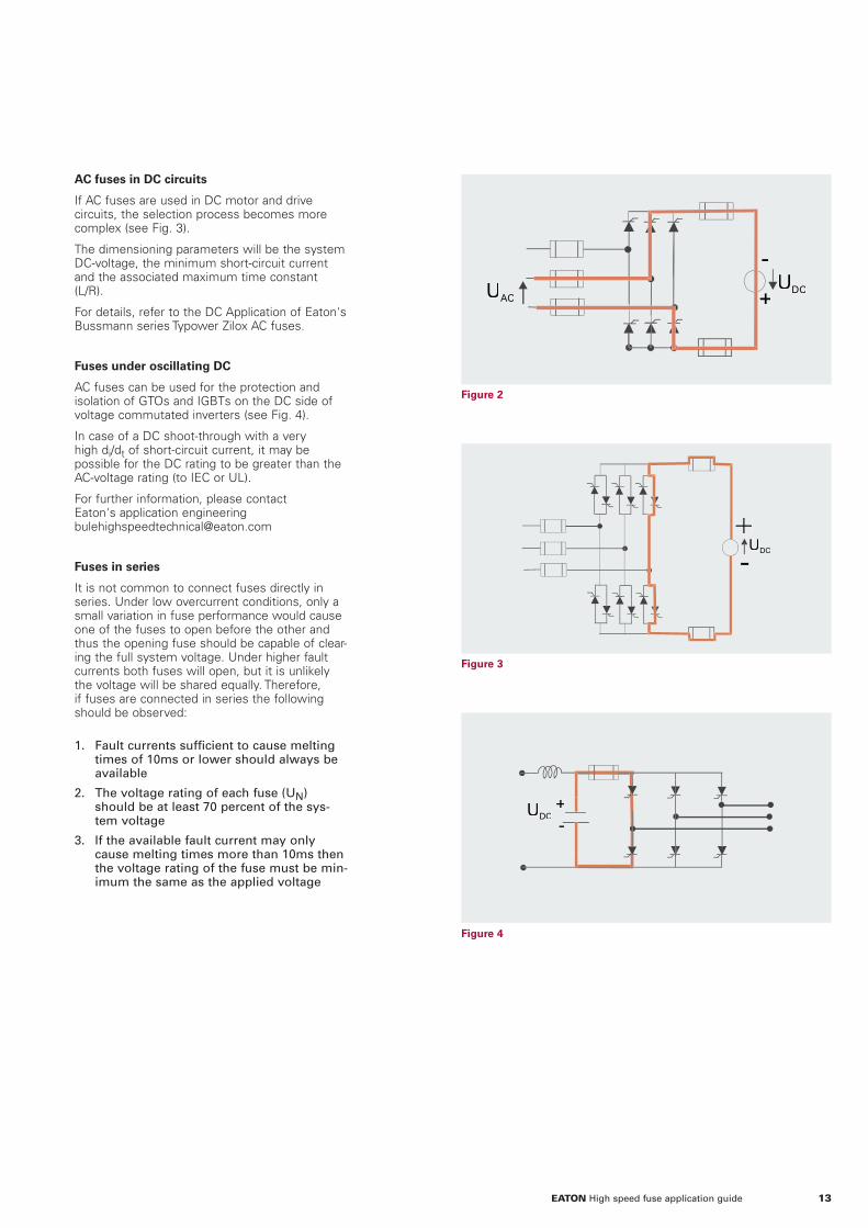
Figure 4
Figure 3
Figure 2
AC fuses in DC circuits
If AC fuses are used in DC motor and drive circuits, the selection process becomes more complex (see Fig. 3).
The dimensioning parameters will be the system DC-voltage, the minimum short-circuit current and the associated maximum time constant (L/R).
For details, refer to the DC Application of Eaton's Bussmann series Typower Zilox AC fuses.
Fuses under oscillating DC
AC fuses can be used for the protection and isolation of GTOs and IGBTs on the DC side of voltage commutated inverters (see Fig. 4).
In case of a DC shoot-through with a very high di/dt of short-circuit current, it may be possible for the DC rating to be greater than the AC-voltage rating (to IEC or UL).
For further information, please contactEaton's application [email protected]
Fuses in series
It is not common to connect fuses directly in series. Under low overcurrent conditions, only a small variation in fuse performance would cause one of the fuses to open before the other and thus the opening fuse should be capable of clear-ing the full system voltage. Under higher fault currents both fuses will open, but it is unlikely the voltage will be shared equally. Therefore, if fuses are connected in series the following should be observed:
1. Fault currents sufficient to cause melting times of 10ms or lower should always be available
2. The voltage rating of each fuse (UN) should be at least 70 percent of the sys-tem voltage
3. If the available fault current may only cause melting times more than 10ms then the voltage rating of the fuse must be min-imum the same as the applied voltage
-
+UDCUAC
UDC+-
UDC
+-
13EATON High speed fuse application guide

Part 1 — Basic selection
This part covers the basic selection criteria for only the fuse’s rated current and not the influence from overload and cyclic loading. The actual RMS steady-state load current passing through the fuse should be lower or equal to the calculated maximum permissible load current called Ib.
Ib = In × Kt × Ke × Kv × Kf × Ka × Kb
Ib The max permissible continuous RMS load current*
In Rated current of a given fuse
Kt Ambient temp. correction factor per Fig. 1
Ke Thermal connection factor per Fig. 2
Kv Cooling air correction factor per Fig. 3
Kf Frequency correction factor per Fig. 4
Ka Correction for high altitude
Kb Fuse load constant. For fuses with porcelain body it is normally 1.0 (see data sheet) For fiber body fuses the factor is normally 0.8
In case of water cooled fuse terminals, please consult Eaton's application engi-neering [email protected]
*NB: For any periods of 10 minutes dura-tion or more the RMS-value of the load
current should not exceed this.
The maximum current density of the busbars on which the fuses are mounted should be 1.3A/mm2 (IEC 60269 part 4 defines 1.0 to 1.6/mm2). If the busbars carry a current density more than this then the fuse should be derated.
For example, a 200A square body fuse is mounted onto a busbar with a cross sectional area of 120mm². For a 200A fuse the minimum cross sectional area of the busbar to meet the 1.3A/mm² requirement should be 154mm² (200A/1.3A/mm²). As the actual busbar size is only 78 percent (120mm²/154mm²) of the recommended size, the fuse must be derated.
If two connections are not equal, the respective Ke factor can be found using the following formula: (K1 + K2)/2.
Fuse mounting inside the box etc., will reduce the convection cooling compared with the IEC conditions.
An additional Ke factor should be chosen here based on judgement. Often, box mounted fuses are given an additional Ke factor of 0.8.
Fuses under high frequency load (like in voltage commutated inverters) call for special attention. At these frequencies, the current carrying capability can be reduced due to the imposed skin and proximity effect on the current-carrying elements inside the fuse. Using the curve given in Fig. 4 normally ensures a sufficient margin.
When fuses are used at high altitudes there is reduced cooling effect on the fuse as the density of the atmosphere reduces.
Correction Ka should be applied to the fuse’s continuous rating when the applica-tion is above 2000m:
Where:
I = Current rating at high altitude
In = Rated current of a given fuse
h = Altitude in meters.
Rated current dimensioning
The fuse’s rated current is the RMS
current it can continuously carry
without degrading or exceeding the
applicable temperature rise limits
under well defined and steady-state
conditions. This is in contrast to
semiconductors, whose rated current
is given as a mean or average value.
Many conditions can effect the
current carrying capability a fuse and
to prevent premature ageing, follow-
ing Parts 1, 2 and 3 below will allow
the rated current selection to be on
the safe side.
The percentage of the recommended busbar size
Figure 1 Figure 3
Figure 2 Figure 4
The curve shows the influence of forced air cooling on the fuse.This curve shows the influence of the ambient temperature on the fuse’s current-carrying capability.
I =In x 1 - h - 2000100
x 0.5100
((( (
14 EATON High speed fuse application guide

Figure 5
Figure 6
Example 1
A 200A rated square body fuse is applied at an ambient temperature of 40C°, and wired with cables having a cross sectional area of 120 mm² which is only 78 percent of the recommended size (1.3A/mm²). Forced air cooling is established at a rate of 4m/s. The frequency of the load current is equivalent to 3000Hz. What would be the maximum allowed steady-state RMS current Ib?:
Ib = In × Kt × Ke × Kv × Kf × Ka × Kb
Ib = 200 × 0.9 × 0.98 × 1.2 × 0.85 × 1 × 1 = 180A RMS
Based upon:
In = 200A
Kt = 0.9 , Fig.1 for 40C° ambient temperature
Ke = 0,98, Fig. 2 for 0.78 × IEC
Kv = 1.2, Fig. 3 for 4m/s forced air cooling
Kf = 0.85, Fig. 4 for a frequency of 3000Hz
Ka = 1, sea level, below 2000 meters
Kb = 1
In other words the 200A fuse should only be subjected to a maximum 180A RMS under the described steady-state conditions.
Control of the fuse amperage
The maximum permissible steady-state load current Ib of a fuse can be checked empirically by making simple voltage measurements under actual operating conditions. This should be done after the fuse has been installed in its operating location and loaded at the calculated Ib value:
E2/E1 × (0.92 + 0.004 × t) ≤ N
Where:
E1 = Voltage drop across fuse after 5 seconds
E2 = Voltage drop across fuse after 2 hours
t = Air temperature at start of test in C°
N = Constant (if available, from data sheet, normally 1.5 or 1.6)
Part 2 — Infl uence of overloads
The maximum overload current Imax that can be imposed on the fuse found under Part 1 depends upon the duration and frequency of occurrence.
Time durations fall into two categories:
1. Overloads longer than one second
2. Overloads less than one second (termed impulse loads)
The following table gives general applica-tion guidelines. In the expression Imax < ( percent factor) × It, It is the melting current corresponding to the time t of the overload duration as read from the time-current curve of the fuse. The limits given permit the determination of Imax for a given fuse rating or, conversely, the fuse current rating required for a given overload, expressed by:
Imax < ( percent factor) × It
Typical examples of load cycles including overload currents are given below:
• The percentage factor for each overload should be checked against the melting curve of the selected fuse in question, based upon the guidelines in Part 1
• There is a grey area between a sole over-load and a pure cyclic load situation. In particular, the last of the three examples shown is typical of this dilemma and for safety, treat a cycle like this based upon the guidelines in Part 3 of this chapter.
Frequency ofoccurrence Overloads (>1 sec) Impulse loads (<1 sec)
Less than one timeper month
Imax <80 percent × It Imax <70 percent × It
Less than twiceper week
Imax <70 percent × It Imax <60 percent × It
Several times a day Imax <60 percent × It Imax <50 percent × It
15EATON High speed fuse application guide

Example 2
A 200A fuse has been selected and is subjected to temporary overloads of 300 amps for 5 seconds. These overloads occur three to five times a day. From the time-current curve of the fuse we find It: the melting current corresponding to the timet = 5 seconds of the overload duration to be It = 600A.
From Fig. 5 the actual limit is:
Imax < 60 percent × It = 60 percent x 600 = 360A
This means that temporary overloads of up to 360A can be withstood and the 200A fuse selected (and subjected to the 300A for 5 seconds 3 to 5 times a day) will work in this application.
Part 3 — Cyclic loading
Cyclic loading that leads to premature fuse fatigue is defined as regular or irregular variations of the load current, each of a sufficient size and duration to change the temperature of the fuse elements in such a way that the very sensitive restrictions (necks) will fatigue. In order to avoid this condition, calculations can be made to ensure there is an appropriate safety margin for the selected fuse.
While using the following empirical rules will cover most cyclic loading conditions, it is impossible to set up general rules for all applications, so please contact Eaton application engineering([email protected]).
1. Ib > Irms * G
Ib is the max permissible load current found based upon the criteria laid out in part 1, IRMS is the RMS value of the cyclic loading. Some cyclic load factors G can be found from the example profiles in Fig. 7, or can be provided upon request.
In many cases a sufficient safety margin is assured by using the following G value:
G = 1.6
The required rating for the fuse can there-fore be found using the following formula:
Once a fuse has been selected using the above criteria, a check is required to see if the individual load pulses (each expressed in Ipulse, tpulse coordinates) have a suffi-cient safety margin B in relation to It of the fuse’s melting curve. It is the melting current of the fuse corresponding to the duration of the pulse (t = tpulse), and B to be found per Fig.8.
2. Ipulse < It * B
This should ensure a sufficient lifetime of the fuse when subject to the given loadings.
Figure 7
Figure 8
In ≥
In IRMS * G
Kt * Ke * KV * Kf * Ka * Kb
16 EATON High speed fuse application guide

Figure 8
Example 3
The following cyclic load exists: 150A for 2 minutes followed by 100A for 15 minutes.
This requires a cyclic load factor of G=1.6 (refer to example profiles) and the RMS-value of the cyclic loading for period T = 17 minutes is determined by:
Ib > Irms * G = 107*1.6 = 171A
Assuming there are no derating factors (i.e., Kt = Ke = Kv = Kf = Ka = Kb), this is the dimensioning current for the rating of the fuse In.
A 200A fuse may be sufficient in this case however a check by B factor still remains in order to secure that the pulse keeps a sufficient safety distance to the melting curve:
Ipulse < It * B = 440A *0.32 = 141A
It = 440A can be found from the time current curve of the actual 200A fuse for tpulse = 2 minutes (as per Fig. 9) and B = 0.32 from Fig.8 based upon T=17. In this case Ipulse = 100*1.5 = 150A and therefore the above equation is not satisfied and a larger rating fuse should be selected – 250A.
Fuses in parallel
There are many applications that use fuses in parallel.
As the surface area of two smaller fuses is often greater than an equivalently rated larger fuse, the cooling effects is also larger. The result may provide a lower I²t solution, providing closer device protection or a lower power loss solution.
Only fuses of the same type or part number should be used in parallel, except-ing that only one may be required to provide indication.
All the fuses should be mounted to allow equal current and heat flow to the connec-tions. In larger installations, it is best to parallel fuses of close cold resistance values.
The I²t value of parallel fuses is given by:
I²t x N²
where N is the number of parallel fuses connected together.
Mountings should ensure at least 5mm between the adjacent parallel fuses.
rms10717
)15*100()2*150( 22
A≈+
17EATON High speed fuse application guide

The circuit configuration for these applica-tions varies a lot and some of the most typical circuits are found on the following page, together with information on how to find relevant RMS-load current level for fuse installation.
All of these fuse types may operate at just a few amps or at many thousands of amps. The circuit operation principles are usually the same for all ratings, whereas the level of protection depends on issues like the need to protect against accidents and personal injuries, security of compo-nents, etc.
Some aspects of the circuits and their protection are common to many applica-tions. These will be covered here with more specific details covered in following sections.
Applications are broadly grouped into those that are AC and those that are DC. However, in modern circuits many systems involve AC and DC.
The applications that utilizes DC to AC inverters- such as variable speed AC drives, uninterruptible power supplies (UPS) - can usually be considered in two parts for fusing. First the AC to DC converter and then the inverter section. This guide will describe the AC part first and consider the rectifier systems and switches.
RMS Currents in common bridge arrangements
The most common circuits involve recti-fiers converting AC to DC. There are a number of ways in which the supply transformers and rectifying devices may be arranged. For the purposes of the following schematics, diodes are shown (although thyristors or GTOs could be used). These would give control over the output voltage or power.
There are common places to fit fuses in rectifier circuits. The RMS current at these positions varies depending on the cycle amount the current will be flowing. This is described for diodes, but for controlled circuits these values may be different. However, they will not exceed those shown, as this is the same as the controlled device being permanently in an ON state. The most common arrangements are shown in the following schematics.
The pros and cons of locating fuses in each of the positions will be considered in the detail for each of the configurations later.
Circuit1 is not often encountered in power electronics systems. The half wave output would be inefficient with much distortion reflected to the supply.
Application areas — general
Semiconductors and associated high speed fuses are used in many applications
such as AC drives, DC drives, traction, soft starters, solid state relays, electroly-
sis, induction furnaces and inverters. The power source for these may be grid
supply, local generator or battery.
18 EATON High speed fuse application guide

Typical rectifi er circuits
Fuses are RMS-devices and based upon the 100 percent output DC-load
current average, the relevant RMS-load currents I1, I2 and I3 can be found.
19EATON High speed fuse application guide

Protection by fuses
Internal and external faults
As can be seen in the schematics, fuses may be placed in different circuit posi-tions. Fuses may be placed in series with the semiconductor devices, in the supply lines, and sometimes in the output lines. Only the fuses in the legs of the bridge will allow maximum semiconductor steady state current carrying capacity as the minimum fuse RMS current is in this location.
In the design of high power rectifier equip-ment, there are two types of faults that must be accounted for:
A. Short-circuit of an individual rectifier cell - generally termed an “internal fault.” Failure to open in the circuit of a silicon power rectifier is rare. This type of fault, however, can be ascertained by the use of detection circuitry.
B. The appearance of a short-circuit or excessive load at the output ter-minals of the equipment; generally termed an “external fault.”
Protection from internal faults
In order to protect healthy rectifier cells in the event of an internal fault, fuses should be placed in series with each rectifier cell.
Further consideration for rectifiers with parallel paths
It is important to point out that in the design of high power rectifier equipment, continuity of supply in the event of an internal fault is often a desired feature. The equipment must be designed to provide the required output under all load condi-tions with one or more semiconductor devices non-operative according to the manufacturer’s specification.
To ensure continuity in the event of an internal fault, the fuse connected in series with the faulty arm of the bridge must open and clear without opening other fuses connected in series with healthy rectifier cells.
In order to satisfy this condition, the total I²t of the single fuse must be less than the combined pre-arcing I²t of all the fuses in one arm of the equipment, namely :
I²t2< I²t1 x n²
Where:
• I²t2 total I²t of the single fuse
• I²t1 - pre-arcing I²t of each fuse
• n the number of parallel paths in each arm of the equipment
Strictly, to allow for non-uniform current sharing in the parallel paths n should be replaced by: n/(1 + S) where S is the uneven sharing, usually between 0.1 and 0.2 (10 percent and 20 percent).
In addition, should the design specify that continuity of supply must be maintained in the event of one or more devices being non-operative, the “n” in the above formula must be replaced by (n - x), where x is the required number of non-operative cells.
Where “n” is less than 4, experience has shown that protection of the above nature is often difficult to achieve. In applications utilizing both line and individual cell fuses, a check must be made to ensure that the cell fuse selectively coordinates with the line fuse in the case of an internal fault (i.e., the total I2t of the cell fuse must be less than the pre-arcing I2t of the line fuse):
I²t1 < I²t2Where:
• I²t1 = total I²t of cell fuse
• I²t2 = pre-arcing I²t of line fuse
Protection from an external fault
In the event of an external fault, it is unde-sirable to have all the individual rectifier fuses open. It is practice, there-fore, to include a fuse in series with the supply line.
To ensure that the line fuse clears before the individual cell fuse, the total I²t of the line fuse must be less than the combined pre-arcing I²t of the fuses utilized in one arm of the equipment, i.e.:
I²t1 < I²t2 x n²
where:
• I²t1 - total I²t of line fuse
• I²t2 - pre-arcing I²t of each cell fuse
• n: cell fuses in parallel
Service interruption upon device failure
The majority of faults in low and medium power rectifying, and converting equip-ment, falls into this category. Fuses in series with the semiconductor devices, or in the supply lines, are used for protec-tion against internal and external faults. Applications include:
1. Variable speed motor drives
2. Heater controls
3. Inverters
4. Low power rectifiers
Care must be taken in inverter circuits that correct DC-voltage ratings are chosen for each application. Also, DC faults can occur upon device failure in bridge circuits when other power sources feed the same DC bus, or when the load consists of motors, capacitors or batteries. Example 1 in the worked examples section illustrates the protection of a typical DC thyristor drive.
Non-interrupted service upon device failure
Service interruptions cannot be tolerated in large rectifying plant such as DC supplies for electro-chemical applications.
As discussed earlier, these applications employ several parallel paths (n > 4) in each leg of the rectifier. Each of these parallel paths are individually fused to isolate faulty devices (see worked example section). In applications where a large number of fuses are used, the detection of the open fuse is made easier by indica-tors on the fuses, which may be made to actuate a microswitch for distant warning.
In principle, the fuse should carry all the required continuous current and any
expected overloads, and when a fault occurs it should limit the energy passing
through the semiconductor to a value that prevents damage.
20 EATON High speed fuse application guide

Fuses under DC conditions
The inductance in a DC circuit limits the rate of current rise. The time spent
for the current to reach 63 percent of the final value is called the time
constant, also referred to in terms of L/R.
The rate of current rise influences the energy input rate that melts the fuse element. This influences both the fuse’s melting time-current characteristic and the peak current let-through. For long operating times (greater than 1 second) the heating effect of an alternating current is the same as DC and the characteristics will merge. See Fig. 2.
Many circuits have the time constant of between 10 and 20 milliseconds and thus IEC specifications require testing between these values. Time constants longer than 20 milliseconds are not often found outside of traction third rail applications, where long rail lengths give extremely high inductance to resistance ratios. For short-circuit considerations, the value of the circuit time constant under fault conditions should be used. This may be different to the time constant during normal operating conditions.
In many rectifier circuits, even under fault conditions, a fuse will be subjected to an alternating voltage, or when only unidirec-tional the voltage will reduce to zero or close to zero on a regular basis as defined by the supply frequency. In these condi-tions, the extinguishing of the arc inside the fuse, under fault conditions, is assisted by the voltage reducing to zero.
When a fuse is applied in a purely DC application, the fuse arc extinction process will not be assisted by the reducing voltage or the voltage zeros of an AC situation. The inductance in the circuit stores electrical energy. This influences the manner in which the fuse arcing process reduces the current in the circuit, for reasons that are beyond the scope of this guide.
The voltage, under which the fuse can safely operate is dependent on circuit time constants. It should be noted that when the time constant is short, it may be possible for the DC-voltage rating to be greater than the AC-voltage rating (to IEC or UL). However, for most fuses the DC-voltage rating is 75 percent or less than the AC-voltage rating - and this DC rating decreases further as the circuit time constant increases.
The arc voltage generated by the fuse during operation will also vary with respect to the system voltage. The variation of arc voltage with respect to applied voltage will be different between AC and DC systems. However, in most cases, it is acceptable to use the data provided for AC conditions.
Unless special design features are included, fuses should not be asked to clear against low overcurrents in DC circuits. The performance in this area may be a limiting factor on fuse selection.
DC fed systems
The vast majority of applications involving DC fall into the type where an AC supply is rectified to supply a load. This load may be passive such as an electrolysis cell or complex as regenerative drive.
There are a number of circuit types that require special consideration. These include those with batteries or capacitors, and those where the motor drive is regenera-tive. In large electrolysis systems there are often considerations of parallel devices and fuses, this is covered elsewhere in this guide, as are regenerative drives.
Battery as a load
In principle, battery-charging circuits are similar to electrolysis systems.
Standard bridge configurations are normally used for these systems. Fuses may be positioned in the AC line, arm or the DC line. The use of arm fuses not only gives closest semiconductor device protection, but also protects the bridge against internal bridge faults and faults in the DC system.
In high current circuits the control of the current is often by phase control using thyristors. In lower power systems the fault current may be limited only by the impedance of the transformer’s secondary side and the rectifier will be only diodes.
In the former, high fault currents can occur if the control to the thyristors fail. Selection of fuses for this type of circuit is like that for a DC drive (detailed elsewhere in this guide).
However, in a diode only system, in the event a battery is connected in reverse polarity, the fault current will pass directly through the diodes. The resulting fault current will only be limited by the internal impedance of the battery. Fast isolation is required to protect the diodes and to limit the I²t in the diode.
Due attention has to be paid to the possible pulse duty for which a battery charger may be. Many controlled charger circuits have a high charge rate for a short time before a lower continuous rate is applied. Guidance on this aspect is given in the section on cyclic loads.
63.2 percent
Time
Cur
rent
T 2T 3T 4T 5T
Figure 1 Figure 2
21EATON High speed fuse application guide
Battery as only source
The use of batteries is vast and increasing due to the demands for renewable energy where battery applications are common and essential as power storage devices.
Protecting a battery or batteries is particu-larly difficult due to battery characteristics under fault conditions. The problem is made more difficult by the huge number and variation of manufacturers and battery types available.
A high speed fuses can be a good choice to protect batteries under short-circuit fault conditions due to the superior current limit-ing effect of the fuse.
However, for a high speed fuse to operate effectively, it requires that the fault current is of a sufficiently high enough level to melt the fuse element quickly. The rate of rise (time constant) of fault current has to be fast enough to allow the fuse to clear the DC arc generated during fault clearing. DC fault conditions are difficult to fuse and misapplication can in some cases cause stress failure of the fuse. Fault current under short-circuit conditions is severely limited by the batteries own internal impedance and state of charge within the battery. If a battery is fully charged there may be sufficient energy to allow the fuse to operate, but as the battery loses charge this could reduce the level to well under that required by the fuse.
As with long time constants typically greater than 15ms insufficient fault current could cause a similar failure of the fuse. Fault currents applied to the fuse that fall above the A-A line at the dotted area of the time current curve would be of major concern.
It is essential that all the possible battery parameters are known before attempt-ing fuse selection for battery protection. Details of the battery and data sheets should be obtained from the manufacturer. It may be required that the selected fuse can only be used providing the batteries are sustained at a certain level of charge and the manufacturer can guarantee a short-circuit time constant in the event of a short-circuit.
A high speed fuse will, of course, only provide short-circuit protection. For cable protection, a more general purpose fuse should be applied that is able to operate under low overload conditions. This causes other problems as general purpose fuses are often not able to handle DC voltages to the same degree as high speed fuses. A sustained low overload fault at high DC voltages may require a fuse specifically designed for DC applications to provide safe reliable fuse protection.
Please contact Eaton's application engi-neering ([email protected]).
22 EATON High speed fuse application guide

DC application of Eaton's Bussmann series square body AC fuses
The information below applies specifically to the 660V, 690V, 1000V, and
1250Vac series of standard Typower Zilox fuses, when these fuses have
not specifically been proven and have not been specifically assigned a DC
voltage capability.
These fuses can also be used in circuits where DC faults occur. However, due care must be taken in the selection process. It is recommended to prove the fuses after following the selection process described below as this is only a guideline.
The interrupting capability of the fuse depends on the combination of the:
• Applied DC voltage
• Circuit time constant (L/R)
• Minimum prospective short-circuit current, Ipmin, of the circuit
• Pre-arcing I²t of the fuse selected
To correctly apply a fuse, a factor F that relates the melting I2t to the prospective current must be used.
In order to determine factor F in Fig. 3, use the curves in figure 1 or 2. Figures 1 and 2 show the dependency of the maximum applied DC voltage on L/R, with 3 levels of Ip as a parameter indicated as 1, 2, and 3. Select the curve 1, 2 or 3 by choosing the curve above the point from the known available voltage and circuit time constant
If no curve exists above the voltage-L/R point then a fuse with a higher AC rating than 1250V must be chosen. – Contact Eaton's application engineering for assis-tance ([email protected].
Factor F is found in Fig. 3 as a function of the circuit L/R and the selected curve 1, 2, or 3 as parameter.
To check if the minimum level of available current (Ipmin) in the actual DC circuit is
in accordance with the selections made in Fig. 1 or Fig. 2, the following condition must hold true:
Where I²t is the pre-arcing integral (from cold) in A2s of the fuse in question, and it is important the fuse is capable of inter-rupting this minimum current.
In Fig. 4, the peak arc-voltage of the fuse in worst case situation can be found as a function of applied DC voltage.
ote: N Note: Where fuses in a catalog series have a reduced AC voltage capability, the DC voltage capability will be reduced by a similar percentage. E.g., 2000A size 3 from the 690V range has an AC voltage rating of 550V so the DC voltage rating will be reduced by 20 percent.
[A] tI x FI 2≥pmin
Figure 3
Figure 1
Figure 4
Figure 2
23EATON High speed fuse application guide

Calculation example
Typower Zilox 1100A, 1250V, AC, 3/110, 170M6149, 575,000 A²s (pre-arcing integral).
Applied voltage E = 500Vdc
Prospective current Ip = E/R = 500/16 = 31.3 kA
Time constant L/R = 40ms (0.64/16)
Using Fig. 2, it is found that having 500V as applied DC voltage with L/R = 40ms, curve 1 has been passed, and this leaves us with curve 2 in order to be on the safe side.
From Fig. 3 we find F = 26.5 based upon the combination L/R = 40ms and curve 2.
Together with the pre-arcing I²t=575,000 A²s of the actual fuse, this calls for:
Checking with the actual circuit parameters, it can be seen that the breaking capacity of the selected fuse holds true, having the following main parameters fulfilled:
1. The maximum applied DC voltage is 500V
2. The time constant L/R is 40ms, up to 46ms could be allowed, OK and
3. Minimum of Ip= 20kA is needed, having actually 31.3kA is OK.
The peak arc voltage generated by the fuse can be found to be lower than 1900V, according to Fig. 4.
LR
E
R 16m L= mH0.64m= Ω16m
Fuse
Figure 3
Figure 1
Figure 4
Figure 2
min. I = 20kA (26.5 x 575.000)p
24 EATON High speed fuse application guide

Photovoltaic systems
Fuses for such installations should meet the requirements of EN 60269 Part 6 (2010). In PV systems it is important to protect the PV panels from excessive current in the event of a failure of one of the PV modules or panels. In most systems, the available current is extremely limited, so only gPV fuses should be employed to protect strings. Eaton's Bussmann series gPV fuses are capable of interrupting very low overcurrents at full voltage.
However, in the event of a fault on the system and within the inverter, the fuses are also capable of interrupting high fault currents.
Selecting the fuse with the correct current and voltage rating is similar to that of selecting any fuse. The fuse must be capable of interrupting the highest available voltage in the system and at the lowest available current (when the PV panels are coldest). However, the fuse must also have a current rating sufficient for the highest current available (hottest panel at high illumination) with due regard to ambient temperature, cyclic loading, mounting arrangements and altitude as explained in this guide.
Eaton recommends always using fuses in each string and one in the positive and one in the negative lines however many “strings” are used in the system
In large systems it may also be necessary to use larger gPV rated fuses in a “branch” situation to protect the cables, such a position may be referred to as branch, intermediate or array fuses.
For suggested reading on this subject, please consult Eaton's Bussmann series photovoltaic application guide www.eaton.com/bussmannseries
Photovoltaic (PV) systems present special cases for fuse protection.
The requirement to use fuses in PV systems is included in the installation
requirements for many countries.
25EATON High speed fuse application guide

To select the rated fuse voltage, the types of faults that can occur in the equipment must be known.
The fuses could be applied as F2 fuses only, or as F1 + F3 fuses.
In rectifier operation there are three possible fault types.
Internal faultThis fault is due to a thyristor loosing its blocking capacity, leading to a short-circuit between two AC lines.
Fuses selection for protecting regenerative DC-drives
In principle, the fuse should carry all the required contin-
uous current and any expected overloads, and when a
fault occurs it should limit the energy passing through the
semiconductor to a value that prevents damage.
+-
UDC
F1
F2 F3
UAC
+
-UDC
UAC
+
-UAC UDC
+
-UDC
UAC
+
- UDC
+
-VaUAC UDC
Cross-over faultThis fault occurs when a misfiring of one of the thyristors in the inverter bridge results in an AC line-to-line short-circuit.
External faultThis fault is due to a short-circuit on the DC output side (motor flash-over for example). The applied fault voltage is again equal to the AC line-to-line voltage.
Conclusion on the rectifi er mode
In all three fault types, the short-circuit current will pass through two fuses in series. This means that the two fuses will normally help each other in clearing the fault. Nevertheless, for safety, as a minimum, the rated fuse voltage UN has to be selected according to UN ≥ UAC (pay attention to the commutation fault situation). When it comes to protecting the semiconductor and the I²t calculation, it is an advantage to have two fuses in series. In the short-circuit path,if the prospective current is very large, the I²t can be calculated with almost equal sharing of the fault voltage. At smaller fault current levels it is not considered safe to use total equal voltage sharing. Normal procedure is to use 1.3 as a safety factor. Hence, the I²t values are calculated at:
UAC × 0.5 × 1.3 ~ 0.65 × UAC
There can also be three fault types while operating in the regen-erative mode.
Commutation faultThis fault is due to a thyristor losing its blocking capability while there is a direct line-to-line voltage across it. This leads to a short-circuit where the AC-voltage is superimposed on the DC-voltage.
Loss of AC-powerIf the AC-voltage fails, a short on the motor acting as a generator occurs through the thyristors and the transformer.
DC shoot-throughThis fault occurs due to one thyristor misfiring and leads to a DC short-circuit.
26 EATON High speed fuse application guide

Conclusion on the regenerative mode
As it can be seen from the fault circuit, there will also (in all three fault types) be two fuses in series, but the fault voltage greatly differs.
During the commutation fault, the fault voltage is the AC-voltage added to the DC-voltage. In the worst case, the peak voltage will be about:
0.8 × 1.35 × UAC + UAC × √2 ≈ 2.5 × UAC
Generally, the fault voltage is half a sine wave at a lower frequency. E.g., the RMS value of the fault voltage will be about:
2.5 × UAC × 1/√2 ≈ 1.8 × UAC
Though this type of fault is very rare, it will dictate the dimensioning voltage for the rated voltage of the fuse in this system, meaning the rated fuse voltage should be in accordance with:
UN ≥ 1.8 × UAC
If an I²t calculation is needed (mainly done for internal fault only), the dimensioning I²t voltage having two fuses in the same short-circuit path will give:
UN = 1.8 × 0.5 × 1.3 UAC = 1.2 × UAC
For the other two fault types under inverter operation, the fault voltage will be a pure DC-voltage. Normally, the maximum voltage will be:
0.8 × 1.35 × Vac = 1.1 × UAC
A normal AC fuse can operate under DC conditions with some limit to the supply voltage, the minimum available fault current, and the time constant.
Please refer to the section DC Application on Eaton's Bussmann series AC fuses.
During the DC shoot-through fault, the only impedances in the circuit are in the motor and inverter branch. The minimum prospec-tive fault current is normally very large and the time constant in the circuit is small (e.g., 10 to 25ms). Under this condition, having two fuses in series, the I²t value is normally equal to the value obtained under AC at a voltage level of:
UDC × 1/√2 = 1.1 × UAC × 0.5 × 1.3 ≈ 0.5 × UAC
In order to be certain, all data should be available for the motor and other imped-ance in the circuit.
In case of a reduced or total loss of the AC power, the condition is worse. The fault current level can be very low and the impedance of the transformer gives large time constants.
In order to suggest fuses that can function under these conditions it is necessary to have information not only on the motor and the inverter impedance but also on the transformer.
Summary of Voltage Selection for Regenerative Drives: (4Q-Service)
Combination of line voltage and load voltage requires:
Fuse voltage UN 1.8 × UAC (line-to-line)
e.g.,
• 110V System: 200V fuse
• 380V System: 690V fuse
• 690V System: 1250V fuse
For further guidance, please contact Eaton Application engineering department:[email protected].
27EATON High speed fuse application guide

Protecting inverters
There are many equipment types used to convert DC current to AC current
(the DC current may have been created by an AC current rectifier).
Such applications include variable speed AC drives and un-interruptible
power supplies (UPS).
All these inverters work by switching the DC current ON and OFF in a predeter-mined manner. Early inverters using thyris-tors were often of the McMurray form (see diagram). Once turned ON, thyristors continue to pass current until the voltage across them is reversed using numerous components to commutate the devices. The commutation thyristors also required protection.
Typical Inver tor - Thyr istorOne phase of three-phase unit
Filter Inductor
DC Supply
LOAD
FilterCapacitor
L1
Thy1
F1
D1
Commutation
Components
L2
Thy2
F2
D2
F3
Even with fuse protection in the DC link at F3, it is best to use device protection for the thyristors at F1 and F2. To ensure protection in these circuits, it is essential to use the fastest fuses available (and still meet all the current dimensioning) which are also rated with a DC-voltage capability at least as high as the DC link voltage.
The key to fuse selection in inverters is to select the highest speed available that will meet the current and voltage dimensioning requirements.
Voltage selection
Fuses in the inverter must have a DC voltage rating of at least the supply link voltage. Even though in most fault condi-tions there will be two fuses in series, these will not share the voltage equally. Also, in some fault situations the voltage on the DC link may exceed the nominal value by up to 30 percent for a short time.
Current selection
As shown in the inverter circuit schemat-ics, there are several locations to place fuses. As with DC drive circuits, the use of link fuses, or DC line fuses, results in the highest current rating and closest protec-tion is located by individual devices.
As inverter circuits contain high frequency components to the current, and the physi-cal arrangements are compact, proximity effects may influence the fuses and further allowance must be made for current carry-ing capability.
I²t Selection
Due to the magnitude of the fault current from the capacitor and small inductance in the circuit, the current rise rate may be very high. Selection of suitable I²t criteria is not easy as device data may not be available for times below 3 milliseconds, nor fuse information may not be provided for these conditions. Fuse performance will also vary slightly depending on the capacitor size, the circuit inductance and resistance and DC link voltage. Selection by choice of the lowest I²t fuse that will meet the current dimensioning require-ments will be the best way to ensure device protection. Even if device protection is not ensured, this fuse selection will certainly limit the damage to all the circuit components.
It is also important to select a low I²t fuse, and especially if the capacitor is a low value. When a short-circuit occurs in the inverter, the current rises rapidly to a peak and will then decay, the waveform is clas-sical of capacitor discharge. It is important that the fuse has opened and cleared before the voltage on the capacitor has decayed to a low value. If the fuse was to operate at a low voltage on the capacitor, the fuse may not have developed sufficient insulation resistance to withstand the DC link voltage when it is replenished from the supply.
Load
GTO Inverter
With the developments of GTOs, it was possible to switch the current OFF without the use of commutation components. It should be noted that with reducing the complicated trigger (firing) circuits, consid-erable space and costs were saved and energy losses were reduced, too.
Although GTOs are more expensive than thyristors, the component reduction more than compensates for this. In terms of protection there is little difference in the selection parameters. However, the GTO circuits are inherently more reliable with fewer power components to protect.
IGBT as switching device
The advent of the IGBT as a switching device has made control circuits much easier and power dissipation in the power switching sections reduced. The higher switching frequency capability and ease of control allows more efficient use of the pulse width modulation techniques, as well as improved quality of the output waveform.
28 EATON High speed fuse application guide

IGBT inverter
Load
However, the IGBT circuit has some differ-ent protection problems.
In order to reduce switching losses, the inductance of the filter capacitor and IGBTs has to be as low as possible. This is achieved by careful busbar arrangements that often preclude using fuses.
Due to the design of the silicon switching element, an IGBT module can limit current for a short period. In addition, it is often possible to detect fault currents and switch the IGBT OFF before damage occurs. However, if the IGBT is not switched OFF before the device is damaged, the silicon will melt and vaporize.
With plastic IGBT modules, there is another failure mode that occurs before the silicon melts. The internal connections to the IGBTs and other components are thin aluminum wires. Under fault condi-tions, these wires melt and arc, causing the module case to become detached from the base. In some cases, there is damage to the module case. Protection must, therefore, be about protecting the wires and the module case as well as the devices. Unfortunately, there is often no I2t data provided for IGBT modules.
Protection of drive circuits
If damage is caused to the IGBT device or connecting leads, the gate control circuits may become involved with the high voltage and current of the power circuit. To avoid, or at least limit, damage to the control circuits, miniature fuses with a high inter-rupting rating should be used in the drive circuits. Low interrupting capacity glass fuses are not suitable.
Bi-polar power transistors and darlingtons
It is difficult to protect power transistors with fuses. The power transistor usually operates extremely close to its power limits of current and voltage. Only a short excursion beyond the safe operating area will damage the functional aspect of the transistor and even high speed fuses will not react fast enough to protect the device. However, like IGBTs, when the function of the transistor is lost the current is only limited by the low resistance of the damaged silicon and very high currents result. These will melt any connecting wires and will, in the case of press pack configuration, eventually melt the silicon. The resultant arcs will cause the packag-ing to fail with catastrophic results. Even though device protection cannot be offered by fuses, it is still essential to use fuses to prevent case rupture and provide circuit isolation.
29EATON High speed fuse application guide

Example 1 — DC thyristor drive
Basic information
1. 500 Hp Variable Speed Drive.
2. Motor, nominal DC-voltage - 660V.
3. Motor, maximum DC current - 600A.
4. Supply transformer 750kVA, 5 per-cent impedance.
5. Supply voltage - 480V RMS.
6. Overload protection is provided by current limit circuit (direct control of thyristor firing) with a response time of 25 milliseconds.
7. The equipment has to operate at a maximum ambient of 40°C, convec-tion ventilation.
8. The circuit used is a 3-phase thyris-tor bridge with one thyristor per leg.
9. Thyristor particulars: I²t rating 120,000 amp2sec, Peak reverse volt-age withstand Urrm=1600V.
10. No details of cyclic loading are to be included for this example
Basic design
For best protection, device protection with six fuses will be examined (one each Thyristor).
Since the fuses are for short-circuit protec-tion only, this is simply a question of coor-dinating the I²t, peak current and maximum RMS fuse current ratings. Maximum RMS current through each thyristor is given by the appropriate factor for the circuit layout, multiplied by the DC load current
= 0.58 × 600(Fig. 5 in the section Typical Rectifier Circuits)
= 348A
From the catalog a fuse of around 400A with an appropriate physical type is selected. For the application a fuse from the square body fuse type is required. From the data sheet for size 00 fuses rated at 690V and 400A is initially chosen. From the temperature rating graph, Fig. 1 in the section “Rated Current Dimensioning”, a derating to 90 percent is required at 40°C. No other thermal derating factors will be required.
0.9 × 400 = 360A
As this is above the required 348A and its rating would be appropriate.
Next, the fuse I²t has to be confirmed as less than the withstand of the device.
For the 400 A fuse of body size 00 the total I²t is 125,000 at 660V. By observing the factor for I²t with respect to applied voltage on the data sheet it can be seen that the I²t at 480V will be only 0.7 of the value at 660V, or 87,500, which is well below that of the thyristor withstand.
A check of the arc voltage graph on the data sheets confirms that the fuse arc voltage of 1000V will be below the 1600V voltage rating of the thyristor.
Thus the fuse selection of the type 170M2621, body size 00, 690V, 400A, 80mm fixing center can be made. If the power loss of the equipment is critical and there are no physical constraints it may be possible to utilize an alternative solution.
By selecting a higher current rating fuse and using it at a current well below its capability, it will give considerable lowering of the power dissipation.
For this example we can chose a body size 2 fuse of 500A rating. Although the I2t is 145,000 at 660V, this will be reduced to 101,000 at 480V as described above. The power dissipation of the 400A fuse at 348A (87 percent) will be reduced to 80 percent of the 70 watts shown on the data sheet, or 56 watts.
If the 500A body size 2 fuse is used at 348a (70 percent) the 75 watts shown on the data sheet will be reduced to 45 percent or 34 watts.
As six fuses are used, the total power saving by using physically larger fuses will be 132 watts.
Example 2 —DC supply with redundant diodes
A rectifier is to provide a 7500A, 80Vdc supply from a 50Hz source.
Basic information
1. 3-phase diode bridge, six parallel diodes per leg
2. 100 percent overload for 1 minute
3. 55°C ambient-maximum. Air-flow of 4 m/s supplied
4. Bus-bars based on 1A/mm²
5. Diode rating : A. Maximum mean rat-ing (free convection, specified heat sink) 1000A B. I²t rating, 10 millisec-onds - 1,000,000 A²s, Peak reverse voltage withstand Urrm = 500V.
6. Maximum prospective AC fault cur-rent = 125,000A RMS symmetrical
Protection requirements
Fuses must protect the diodes against internal faults, isolating faulty diodes without interrupting the supply.
Design details
To protect this application requires device fuses. Maximum RMS fuse current (allow-ing for one defective diode, n-1 = 5 ; and sharing factor of 90 percent) Load current x factor for rectifier circuit / 0.9 / number of good paths
7,500 × 0.58 / 0.9 / 5 = 966A
The selected fuse must have a current rating above 966A after any other thermal deratings are applied - which are required for high ambient temperature and air cooling. The 1Amm-1 busbar does not need any adjustment.
From the section on Rated Current Dimensioning we find factors of Kt = 0.85 due to ambient temperature and Kv = 1.2 for 4m/s air flow.
The rated current In of the selected fuse must be greater than:
In ≥ 966 / 0.85 / 1.2 = 947A
For the low voltage application, with a low peak reverse voltage diode, a fuse from the low voltage British or USA range is required.
To achieve 950A in the 240 volt British range it would be necessary to use three fuses of 350A rating. To avoid using parallel fuses, the FWA product should be chosen. It is this option that will be considered for the overload considerations.
Overload
The selected fuse must also carry extra 100 percent (or twice rated) current for 60 seconds, once a month. As this is only an occasional overload, it should be possible to select a fuse up to 80 percent of the time-current curve at the 60 second oper-ating time. Put another way, the fuse must have an operating current greater than:
966 x 2 / 0.8 = 2415A
At the 60 second operating time, clearly the FWA-1200AH is suitable for this application.
Worked examples
The previous information can be best understood by studying typical
examples and how to select the appropriate Eaton's Bussmann series fuses to
meet the necessary requirements.
30 EATON High speed fuse application guide
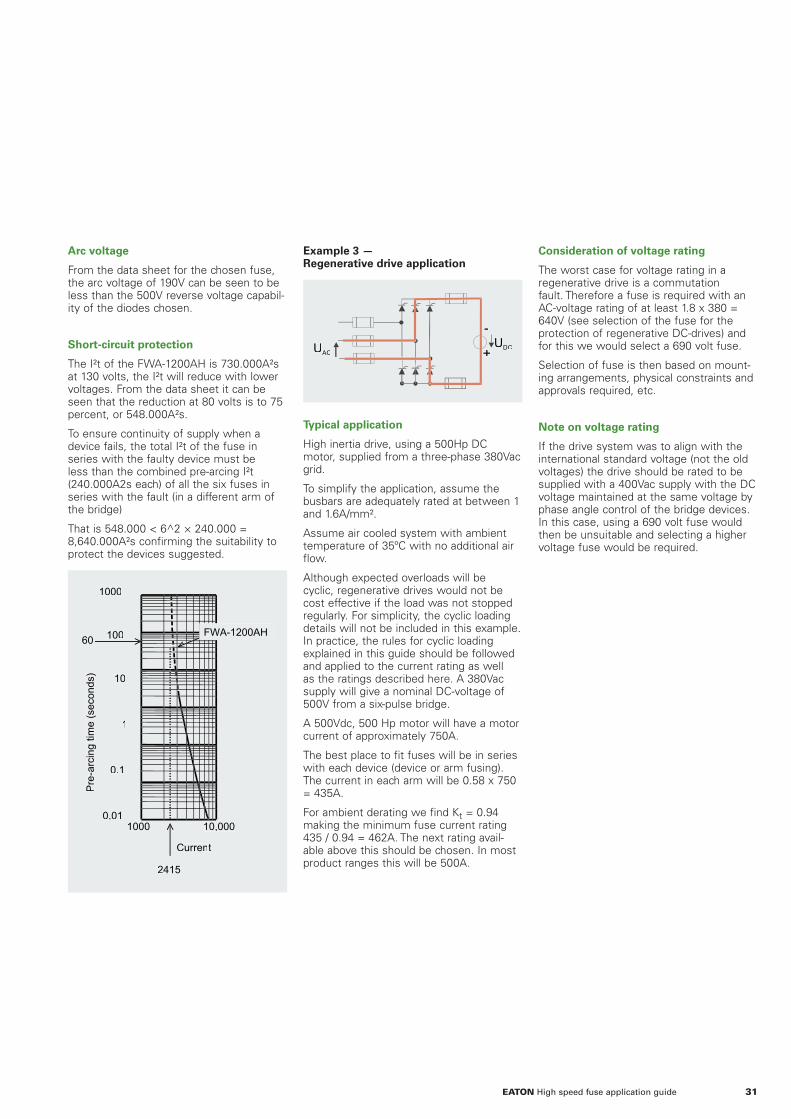
Arc voltage
From the data sheet for the chosen fuse, the arc voltage of 190V can be seen to be less than the 500V reverse voltage capabil-ity of the diodes chosen.
Short-circuit protection
The I²t of the FWA-1200AH is 730.000A²s at 130 volts, the I²t will reduce with lower voltages. From the data sheet it can be seen that the reduction at 80 volts is to 75 percent, or 548.000A²s.
To ensure continuity of supply when a device fails, the total I²t of the fuse in series with the faulty device must be less than the combined pre-arcing I²t (240.000A2s each) of all the six fuses in series with the fault (in a different arm of the bridge)
That is 548.000 < 6^2 × 240.000 = 8,640.000A²s confirming the suitability to protect the devices suggested.
Current
1000 10,000
Pre
-arc
ing
time
(sec
onds
)
100
1000
10
1
0.1
0.01
60
2415
FWA-1200AH
Example 3 —Regenerative drive application
-
+UDCUAC
Typical application
High inertia drive, using a 500Hp DC motor, supplied from a three-phase 380Vac grid.
To simplify the application, assume the busbars are adequately rated at between 1 and 1.6A/mm².
Assume air cooled system with ambient temperature of 35ºC with no additional air flow.
Although expected overloads will be cyclic, regenerative drives would not be cost effective if the load was not stopped regularly. For simplicity, the cyclic loading details will not be included in this example. In practice, the rules for cyclic loading explained in this guide should be followed and applied to the current rating as well as the ratings described here. A 380Vac supply will give a nominal DC-voltage of 500V from a six-pulse bridge.
A 500Vdc, 500 Hp motor will have a motor current of approximately 750A.
The best place to fit fuses will be in series with each device (device or arm fusing). The current in each arm will be 0.58 x 750 = 435A.
For ambient derating we find Kt = 0.94 making the minimum fuse current rating 435 / 0.94 = 462A. The next rating avail-able above this should be chosen. In most product ranges this will be 500A.
Consideration of voltage rating
The worst case for voltage rating in a regenerative drive is a commutation fault. Therefore a fuse is required with an AC-voltage rating of at least 1.8 x 380 = 640V (see selection of the fuse for the protection of regenerative DC-drives) and for this we would select a 690 volt fuse.
Selection of fuse is then based on mount-ing arrangements, physical constraints and approvals required, etc.
Note on voltage rating
If the drive system was to align with the international standard voltage (not the old voltages) the drive should be rated to be supplied with a 400Vac supply with the DC voltage maintained at the same voltage by phase angle control of the bridge devices. In this case, using a 690 volt fuse would then be unsuitable and selecting a higher voltage fuse would be required.
31EATON High speed fuse application guide

Appendix 1International Standards and Eaton's Bussmann series product range
For many years there were no specific international standards for high speed
fuses. Over time, as more manufacturers produced these fuses, a number of
dimensional arrangements became commonplace. high speed fuses are now
becoming a mature product and international standards have been devel-
oped to include the test methods and dimensions..
In Europe
The test requirements of BS88 Part 4 (1976) were the same as IEC 60269-4, with dimensions included for high speed fuses in common use in the UK. IEC 60269-4 included test conditions for AC and DC circuits that were more suitable for high speed fuses than those for industrial circuits. The German VDE specification 0623 Part 23 was specific to the testing of high speed fuses, dimensions were included in DIN 43620 (the same as indus-trial fuses) and DIN 43653 (European high speed square body). Cylindrical fuses were usually dimensionally to French NF C63211.
The latest version of EN60269-4 includes dimensions from all previous European and USA standards for high speed fuses and also includes standardized testing for fuses used in voltage sourced inverters (VSI). This standard now supersedes all these previous standards.
In the United States
Common dimensions became an “industry norm” but until these commonly used dimensions were included in EN60269, they were not included in a published standard. Testing was performed to either customer specifications or when UL component recognition was required and the tests performed would be similar to those of various UL specifications.
The specifications now define test condi-tions and methods. Although these condi-tions are similar, there are some small differences that are beyond the scope of this guide. The major difference between the UL and IEC specifications is that of voltage rating. This difference is common to many electrical specifications and is based on a long historical background. Briefly, European standards require voltage testing at some tolerance above the rated voltage of the components, thus proving a safety margin. Practice in the USA requires testing at the rated voltage. Hence, it is design practice to use the maximum voltage available for dimensioning the rated voltage of components.
Eaton's Bussmann series product range
Various fuse constructions originate from different centers in the world. Eaton manufactures high speed fuses in Europe and the United States. Since the late 1950s, standards have been developed in the above regions for fuses used in the protection of semiconductors. As a result, Eaton's Bussmann series high speed fuse links can be grouped in four world -recog-nized standards:
• European Standard — Square Body
• European Standard — Round Body BS88 (British Standard)
• US Style — North American Blade and Flush-End Style
• Ferrule Fuses — Cylindrical
European standard
In Europe, outside of the United Kingdom, two types of mounting have proved to be the preferred in applications requiring high speed fuses - namely blade type fuses and flush-end versions.
DIN 43653
DIN 43620
Blade type fuses
In Europe, two German standards for the fuse mounting cover most normal styles for Eaton's Bussmann series blade type high speed fuses. They are:
• The DIN 43620 style is used for gG fuses (previously referred to as gL). It is also used for high speed fuses. However, parts of a high speed fuse typically reach higher temperatures during continuous operation than a normal gG fuse. As a result, the DIN 43620 style high speed fuses cannot get a sufficient rating if their holder temperature limits are not to be violated. Knives with holes for mount-ing fuses directly on the busbar are the solution to this issue.
• The DIN 43653 standard came in 1973 with the possibility of mounting the fuse directly on the busbar. Also new holders appeared at the same time. For the most common voltage ratings, fuses with blades according to DIN 43653 will always have fixing centers of 80mm or 110mm.
Flush-end contact type
Like the DIN 43653 style, the flush-end style has proved to be a very efficient and popular high speed fuse. The reason is its installation flexibility. This style is also selected because the current carrying capacity is the most efficient of all fuse types. This is now an industry standard style and is included in the international standard IEC 60269-4-1.
32 EATON High speed fuse application guide

British Standard — BS88
Not surprisingly, this type of mount-ing has found its use mainly, but not exclusively, in the United Kingdom and in British Commonwealth countries. Also, North America manufacturers have begun to specify British style fuses - particularly in applications like UPS equipment with voltages of 240V or less. The advantages are the size, performance, and cost benefit. Utilizing the dimensions given in the BS88 Standard for high speed fuses, which are not physically interchangeable with Industrial fuses to the same stan-dard, has proven to be a very popular and cost competitive solution for high speed fuse applications.
US Style — North American blade and fl ush-end style
Over the years, the North American market has adapted its own mounting style for high speed fuses. Although no published standard exists for these as yet, the industry has standardized on mounting centers that accept Eaton's Bussmann series fuse links.
In many ways, the US Style fuses are similar to the European Style. They are made in both blade and flush-end versions, but two major differences distinguish the two: US Style fuses are usually made in mineral fiber tubes. The fixing centers for US Style fuses will vary depending on both rated voltage and rated current.
Cylindrical fuses
Often referred to as ferrule fuses, this style is internationally used and accepted. The fuses that Eaton manufactures in most cases have dimensions that meet IEC standard 60269. The standard dimen-sions are 10×38mm, 14×51mm, and 22×58mm, and Eaton supplies suitable modular fuse holders. These fuses have proven very popular for applications with ratings up to 660V/100A, due to their easy installation.
33EATON High speed fuse application guide

Appendix 2Fuse reference system
Because of the many Eaton's
Bussmann series high speed fuse
varieties, the reference system is
complex. The use of one particular
reference system in Europe outside
the United Kingdom, another one
in the UK and a third in the US has
become a fact of life. On several
occasions discussions have be held
on changing all references and
replace them with one. However,
all systems have been around long
enough and the references so well
known in the respective markets for
particular styles that the decision
was made to maintain the existing
systems.
Reference system for European high speed fuses
A typical fuse from our European Range could have a part number like 170M3473. However, this will not give any guide to what rating or mounting this fuse will have. Here, the user will first need to know the rating, but the mounting is also of interest. So we use a Type Description to determine what style is in question. Fuses according to the German DIN 43620 standard are always listed by type. For example, DIN 3, DIN 00, etc. For other fuses, according to DIN 43653, flush-end types or special types, this description will reveal the actual type in question. For the reference given above, the type designation will be the following:
1*BKN/50
To interpret this Type Code we have made the following general guideline, that will cover most of the European fuses.
The following tables show the various options for all characters in the above Type Code:
Position 1 — Primary code
The primary code can be one of the follow-ing values:
Position 2 — Body size
Position 3 — Optional
Over the years, Eaton has become a supplier that is able to adapt to customer needs. Therefore, a lot of customized, special fuses are now a part of the product offering. Position 3 in the Type Code might therefore be an S for special. For all such references, please consult Eaton for a mechanical drawing, if this is not already at your disposal.
Position 4 — Mechanical fi xing
Position 5 — Indicator type
Often a fuse will have some type of indicator to show if it has opened. Some indicators are built in and some have to be externally fitted. Optionally they are able to trigger microswitches for remote indica-tion. On the Indicator Position 5 in the Type Code, the following options are standard:
The following describes the Eaton's Bussmann series reference system in detail — style by style.
34 EATON High speed fuse application guide

Position 6 — Indicator position
The indicator position may vary from fuse to fuse. Standard mounting is the so called Position N (North) and alternative positions are E (East), W (West), and S (South):
Position 7 — Center Distance
Indicates center distance for mounting, or overall length of fuses with flush-end contacts, stated in millimeters.
Reference system for BS88 High speed fuse links
Since fuses were first produced in the dimensions that became standardized in BS88 Part 4, fuse technology has improved. It is now possible to manufac-ture fuses with many different operating characteristics. In these dimensions Eaton's Bussmann series high speed fuse links are available in two speed ratings. The T range and the F range. fuses can be selected according to the following codes.
T Range
Position 1 — Current rating
The continuous current rating in amps.
Position 2 — Voltage or style
Position 3 — Body style
In BS88 Part 4, fuses have three diam-eters. Eaton indicates which diameter the fuse has using a letter in Position 3. To achieve additional current ratings of fuses, it is possible to place two fuses in parallel. Eaton provides such fuses, and to indicate that two fuse barrels are used, the letter indicating the diameter is repeated.
Position 4 — T Range
The Eaton's Bussmann series T range fuse has a T in this position. Some special purpose fuses in “standard” dimensions or with special fixing arrangements may have an alternate letter in this position. Contact Eaton for details. For example, 80LET is an 80 amp, 240 volt fuse, 18 mm diameter. 160AEET is a 160 amp, 660 volt fuse with two 18mm diameter barrels and 80mm mountings.
F Range
Position 1 — Current rating
The continuous current rating in amps.
Position 2 — Voltage or style
35EATON High speed fuse application guide

Position 3 — F Range
The Eaton Bussmann series F range fuse (these are faster acting than the T range) has an F in this position.
Position 4 - Body style
In BS88 Part 4, fuses have three diam-eters. Eaton indicates the fuse diameter by means of a letter in Position 4. To achieve additional fuse current ratings it is possible to place two fuses in parallel. Eaton provides such fuses and to indicate that two fuse barrels are used, the letter indicating the diameter is repeated.
For example, 80FE is an 80 amp, 660 volt fuse, 18mm diameter.
Reference System for US High Speed Fuses
Like the European square and round body fuses, the US fuses also have descriptive part numbers. While there is no recognized US dimensional standard for high speed fuses, there are accepted industry stan-dards that Eaton's Bussmann series fuse links meet.
The following tables show the various options for all above positions in the Type Code.
Standard fuses — Type FW
Fuses can be selected by the following codes:
Position 1 — Primary code
All Eaton's Bussmann series US style high speed fuses in the standard program are designated by the prefix FW.
Position 2 — Voltage rating
The AC-voltage rating of the fuse.
L 130 or 150 FWA-80A
X 250 FWX-1A14F
H 500 FWH-175B
C 600 FWC-12A10F
P 700 FWP-15A14F
K 750 FWK-5A20F
J 1000 FWJ-20A14F
L 1250 FWL-20A20F
S 1500 FWS-15A20F
Position 3 — Current rating
For Eaton's Bussmann series high speed fuse links this is usually the continuous current rating.
Position 4 — Technical revision
Eaton constantly improves its products. The Eaton Bussmann series FW range also represents a consolidation after several acquisitions. When this occurs, it is necessary to distinguish each technical revision without changing the existing part numbers. In common with the semicon-ductor industry, Eaton uses a letter code for this purpose. For technical reasons, it may be necessary to maintain more than one of these revisions for some applica-tions, but most applications should use the latest revision.
No mark The first version of this product
A, B, C etc. Later improved version FWP-10B
Position 5 — Fixing style
Most of the FW fuses have center blades with mounting holes. However, flush end mounting (often called Hockey Puck) are common and so are the cylindrical or ferrule types.
Note: Where F is in Position 5, the first version of the product will be designated with an A
Position 6 — Indicator
As standard, the FW fuses do not have visual indication of fuse operation.
Empty Standard product
I Indication by additional external type TI indicating fuse that also takes MA type microswitch (see BS style accessories)
SI Indication by external indicator that also takes 170H0069 microswitch
36 EATON High speed fuse application guide

Special fuses - Types SF and XL
In addition to the standard FW fuses, Eaton offers special purpose fuses along with higher speed versions as an alterna-tive to some of the FW range. These special fuses can be selected by the following codes.
Position 1 — Primary code
Eaton's Bussmann series US style high speed and special purpose fuse links are designated by the prefix SF or XL.
Position 2 — Voltage rating
Generally, this is one tenth of the AC-voltage rating of the fuse. For special purpose fuses, please check with Eaton's application engineering department:[email protected].
Position 3 — Style
F High speed performance. This often also means good dc voltage performance
X Slow speed, often for traction applications
This is only an indication of the letters used, others may be used.
Position 4 — Current rating
On standard high speed fuses this is usually the continuous current rating. For special types, this position may only be an indication of capabilities, as many of these designations are agreed upon with OEMs for special applications.
Position 5 — Technical revision
Eaton constantly improves its products. When this occurs with products outside our main fuse offerings it is necessary to distinguish each technical revision without changing the existing part numbers. In common with the semiconductor industry, Eaton uses a letter code for this purpose. For technical reasons it may be necessary to maintain more than one of these revi-sions for some applications while most applications should use the latest revision.
No mark The first version of this product
A, B, C etc. Later improved version
Position 6 — Fixing style
Most of the SF and XL type fuses have center blades with mounting holes.
Empty Standard blade
HP Flush end fixings — imperial thread
BB Flush end fixings — metric thread
others Agreed with OEM
Position 7 — Indicator
Empty Standard product
I Indication by additional external type TI indicating fuse that also takes MA type microswitch (see BS style accessories)
M Microswitch fitted
37EATON High speed fuse application guide

Appendix 3Installation, service, maintenance, environmental and storage issues
High speed fuses are highly sophisticated and require due care for proper installation
and maintenance. This will ensure reliable performance throughout the fuse’s life. This
section will cover these specific and general issues:
• Tightening torque and contact pressure.
• Mounting Alignment.
• Surface materials of contacts.
• Resistance to vibration and shock
• Service/maintenance
• Environmental issues.
Tightening torque and contact pressure
High speed fuses are electro-mechanical devices. Their proper function depends on the contact quality between the fuse and the connecting cables/ busbars or between the fuse and fuse holder. This is not only important for proper electrical contact, but also because high speed fuses generate a lot of heat that is partly removed via conduction through the fuse’s connections. A poor thermal connection can result in the fuse overheating and reduced life. Therefore it is important to apply the right tightening torque when mounting fuses.
Fuses with fl ush end contacts
For all kinds of flush end fuses Eaton recommends grade 8.8 steel socket set screws according to IS 4026/DIN 913 or ISO 4029/DIN 916. The studs must be tightened carefully applying a torque of 5-8N•m. As a rule, the torque on the nuts relates to the threaded hole dimension in the fuse contact. Eaton recommends a cali-brated torque wrench with a tolerance of maximum ± 4 percent. The following provides the recommended nut tightening torques:
Size / Type Thread hole Torque
mm inches N•m* N•m**
00B M8 20 10
1*B – 1*G M8 5⁄16 20 10
1B – 1G M8 5⁄16 20 10
2B – 2G M10 3⁄8 40 20
3B – 3G M12 ½ 50 40
23B – 23G 2 × M10 2 × 3⁄8 40 20
4B – 4G 4 × M10 4 × 3⁄8 40 20
24B – 24G 3 × M12 3 × ½ 50 40
5B – 5G 5 × M12 5 × ½ 50 40
FWX, FWA,KBC 3⁄8 40 20
* Ungreased thread.** Greased threads (with Rhodorsil Paste 4, etc.)
Special fl ush-end types
Special types like 4SB or 24SB normally have threaded holes in only one end and a plate on the other for mounting on (water cooled) busbars. In such cases, the screw-in studs and nuts for the threaded hole use the values in the torque table while the plate is mounted on the busbars with 50N•m of torque.
Fuses with contact knives
Generally this fuse type is divided into two main groups. Fuses with slotted knives according to DIN 43653 for mounting directly on busbars or in special fuse holders, and fuses with solid knives according to DIN 43620 for mounting in spring-loaded fuse holders.
DIN 43653 — on busbars
Fuses for mounting on busbars are to be tightened with the largest possible bolts/studs, nuts and washers. Use of washers is recommended. The bolts/nuts are tightened with a torque appropriate to their size and tensile strength. E.g., M8 Type 8.8 30N•m (with lubricant) or 50N•m (without lubricant).
38 EATON High speed fuse application guide

DIN 43653 — in fuse holders
Fuse mounted in special made fuse holder must be tightened according to the specification provided with the holder.
Maximum tightening torque for some Eaton's Bussmann series holders are given below:
Part number Torque N•m*
Bolts for holder Bolts for cables/fuses170H1007 4 (M6)
170H3003 – 170H3006** 10 (M8)
Torque lb-in
Conductor set screw Fuse mounting bolt1BS101 120 70
1BS102 275 120
1BS103 275 170
1BS104 375 170
BH-1,2,3 - -
1 lb-in × 0.11298 = 1 N•m* Thread greased with Rhodorsil Paste 4 (Rhone- Poulenc), etc.** For 170Hxxxx holders the above values can be increased by 25 percent if no plastic parts are stressed.
DIN 43620
This kind of holder is equipped with one or more springs to provide the correct contact pressure when the fuse is installed. No tightening recommendations are given. When mounting Eaton's Bussmann series holder 170H3040-47, use a maximum tightening torque of 10N•m to mount it onto the equipment.
Press pack fuses
Some of the most common semiconductors can be stack mounted under an applied clamping force. A range of so-called Press Pack fuses in body type 3P and 4P are available and allow the user to reduce the number of components required. This can be achieved by clamping the semiconductor and the fuse together with a water cooling boxes in a single mounting arrangement. The maximum clamping force a fuse can withstand depends on many factors such as the:
• Length and cross section area of the fuse body
• Temperature gradient between the fuse contacts
• Electrical load conditions
When clamping a fuse into an application, three requirements need to be considered.
1. The maximum clamping force applied to a press pack fuse should not exceed the stated value (please see table below) as this may damage the ceramic body,
2. To ensure safe electrical and thermal contact between fuse contact and the water cooling box or busbar, a minimum force of 2N/mm² needs to be applied to the contact area of the fuse.
3. A maximum for of 15N/mm² can be applied to the mini-mum contact area of the fuse, to ensure safe thermal con-tact pressure. (Please note that the total pressure should not exceed the amounts stated in the table below).
Example values for maximum clamping force can be found in the table below.
Size Single-sided cooling kN Double-sided cooling kN
3P/55 22 30
4P/60 40 50
3P/80 30 40
4P/80 50 60
ote: N Greater permissible clamping force can be applied on some press pack fuses, please consult Eaton's application engineering:[email protected].
If a Press Pack fuse is water cooled at one end and not at the other there will be a difference between the temperatures at each contact end. If the difference between in temperatures is greater than 55K then the clamping values in the above table are invalid. For fuses that use double-sided water cooling, the temperature difference between the fuse contacts is expected to be negligible and the above table values are valid.
Eaton also manufacture a double body Press Pack fuse (24B and 24+B). Please consult Eaton's application engineering([email protected]) when using this fuse in your application.
39EATON High speed fuse application guide

Mounting alignment
Eaton's Bussmann series high speed fuses are generally supplied in a ready-to-install condition.
The fuses are not meant as mounting isolators. Excessive tension, compression and torque from misalignment between fuse and busbars (see example below) should be avoided. If possible, mounting should starting with the fuse followed by the necessary adjustment and tolerance utilization of busbar components.
CorrectEnd tag is not distorted
Not correctEnd tag is distorted
CorrectEnd tag is not distorted
Front view Side view
Not correctEnd tag is distorted
Surface material
The electrical conducting metal parts of Eaton's Bussmann series high speed fuses are usually plated to maintain an acceptable surface condition. Tin is the most common material for the fuse contacts today.
Tin-plated contacts
Concentration – DurationPPM – h According to standard
H2O 12,5ppm – 96h IEC 68-2-43 Kd
SO2 25ppm – 504h IEC 68-2-42 Kd
Most of Eaton's Bussmann series high speed fuse contact surfaces are electro-plated with a 5m layer of tin. This plating provides an excellent electrical and thermal interface with holders or cables/busbars of either pure copper or copper/aluminum plated with tin/nickel or silver.
Many tests and more than 30 years of experience have shown that a tin, nickel or silver-plated surface is both mechanically and electrically stable in the entire temperature high speed fuse temperature range (typical maximum temperature rise of 130°C).
Vibration and shock resistance
High speed fuses should not be submitted to excessive vibration. However, standard high speed fuses can withstand vibration with a maximum 5g magnitude for a long-time basis and 7g for short periods (shocks). Before using fuses in applications with stronger vibration, consult Eaton's application engineering:[email protected].
Service and maintenance
The following points should be observed and checked during main-tenance of electrical cabinets and switchgear.
1. Check tightening torques and examine ceramic fuse bodies for visible cracks. Tighten or replace as needed.
2. Check all fuse indicators. In case of any fuse opening, replace all opened AND unopened fuses that have been subjected to the same the fault current or a part of it. Even if the resistance (W) of the unopened fuses is unchanged, the fuses may be damaged by the fault current and must be changed to avoid nuisance openings.
Environmental issues
Generally, high speed fuses are made from the following basic materials:
• Ceramic
• Fiberglass
• Silver
• Copper
• Brass
• Steel
• Silica sand
Accessories like micro switches and fuse holders are partly made of various plastic materials. For further information on fuse materi-als, contact Eaton's application engineering:[email protected].
Storage
Fuses should be stored in their original boxes under typical warehouse conditions for electro-mechanical products (free from any dirt and dust). Storage conditions should be no more than70 percent relative humidity and in the -40°C to +85°C range.
40 EATON High speed fuse application guide

Arcing I²t
Value of the I²t during the arcing time under specified conditions.
Amp (Ampere)
The measurement of intensity of rate of flow of electrons in an electric circuit. An amp is the amount of current that will flow through a resistance of one ohm under a pressure of one volt.
Amp rating
The current-carrying capacity of a fuse. It is given in amps RMS (root mean square, also called the effective value).
I²t , Amp squared seconds
The measure of heat energy developed within a circuit during the fuse operation. I stands for effective let-through current (RMS), which is squared, and t stands for time of opening, in seconds. It can be expressed as Melting I²t, Arcing I²t or the sum of them as Clearing I²t.
Arcing time
The amount of time from the instant the fuse has melted until the over current is safely interrupted (cleared).
Arc voltage
This is the voltage, which occurs between the terminals of a fuse during operation. The size of the arc voltage for a given fuse is supply voltage dependent.
Breaking capacity / Interrupting rating/ Interrupting capacity
This is the maximum value of prospective current, RMS symmetrical, which a fuse is capable of interrupting at stated conditions.
Classes of fuses/Fuse class
National and International Standards have developed basic physical specifications and electrical performance requirements for fuses with voltage ratings that pertain to specific countries.
The fuse class refers to the designed interrupting characteristic of the fuse. The following fuse class found in IEC 60269 applies to high speed fuses.
• aR - Partial-range interrupting capacity (short-circuit protection only) for the protection of power semiconductors (IEC
Utilization category).
Other classes are:
• gG (gL) — Full-range interrupting capacity (overload and short-circuit protection) for general applications (IEC Utilization category).
• gM — Full-range interrupting capacity (overload and short-circuit protection)for the protection of motor circuits (IEC Utilization category).
• aM — Partial-range interrupting capac-ity (short-circuit protection only) for the protection of motor circuits (IEC Utilization category).
• gR — Full-range interrupting capacity (overload and short-circuit protection) for the protection of Power Semiconductors. (pending).
• gPV — gPV – Full-range interrupting capacity (overload and short-circuit protection) for the protection of Photovoltaic (PV) systems” below gR class.
Clearing (Total operating) time
The total time between the beginning of the over current and the final opening of the circuit at system voltage. Clearing time is the total of the melting time and the arcing time.
Current-limitation
A fuse operation relating to short-circuits only. When a fuse operates in its current-limiting range, it will clear a short-circuit before the first peak of the current. Also, it will limit the instantaneous peak let-through current to a value substantially less than that obtainable in the same circuit if that fuse were replaced with a solid conductor of equal impedance.
Cut-off current / Peak let-through current
The maximum value reached by the fault current during the interrupting operation of a fuse. In many cases the fuse will be current limiting.
Electrical load
That part of the electrical system which actually uses the energy or does the work required.
Fast acting fuse
A fuse which opens on overload and short-circuits very quickly. This type of fuse is not designed to withstand temporary overload currents associated with some electrical loads, when sized near the full load current of the circuit.
Fuse
An over current protective device with a fusible link that operates and opens the circuit on an over current condition.
High speed fuse links
Fuses with no intentional time-delay in the overload range and designed to open as quickly as possible in the short-circuit range. These fuses are often used to protect solid-state devices.
IEC
IEC stands for the International Electrotechnical Commission. It is a non-profit, non-governmental international standards organization that prepares and publishes International Standards for all electrical, electronic and related technologies – collectively known as "electrotechnology".
Inductive load
A load which has inductive properties. Common forms are motors, transform-ers, wound control gear. This type of load pulls a large amount of current when first energized.
Interrupting capacity
Refer to Interrupting capacity.
Interrupting rating
Refer to Interrupting capacity.
Melting time
The amount of time required to melt the fuse element during a specified over current. (See arcing time and clearing time.)
Ohm
The unit of measure for electric resistance. An ohm is the amount of resistance that will allow one amp to flow under a pres-sure of one volt.
Appendix 4Glossary
41EATON High speed fuse application guide

Overload
This is a condition in which an over current exceeds the normal full load current of a circuit that is in an otherwise healthy condition.
Peak let-through current
The instantaneous value of peak current let-through by a current-limiting fuse, when it operates in its current-limiting range.
Power factor
The ratio of active power (kW) to apparent power (kVA) drawn by a load. It corre-sponds to the cosine of the phase angle between the voltage and current (cos).
Power losses/watts losses
The power released in a fuse when loaded according to stated conditions.
Prospective short-circuit current
This is the current that would flow in the fault circuit if the fuse was replaced by a link with an infinitely small impedance. Normally it is given as symmetrical RMS value, also called IP.
Recovery voltage
This is the voltage which can be measured across the fuse connections after operation.
Resistive load
An electrical load which is characteristic of not having any significant inductive or capacitive component. When a resistive load is energized, the current rises instantly to its steady-state value, without first rising to a higher value.
RMS Current
Also known as the effective value, it corresponds to the peak instantaneous value of a sinusoidal waveform divided by the square root of two. The RMS value of an alternating current is equivalent to the value of direct current which would produce the same amount of heat or power.
Semiconductor fuses
Fuses used to protect solid-state devices. See high speed fuses.
Short-circuit current
Can be classified as an over current which exceeds the normal full load current of a circuit by a factor many times.
Short-Circuit Current Rating (SCCR)
The maximum short-circuit current an electrical component can sustain without the occurrence of excessive damage when protected with an overcurrent protective device.
Threshold current
The symmetrical RMS available current at the threshold of the current limiting range, where the fuse becomes current limiting when tested to the industry standard. This value can be read off of a peak let-through chart where the fuse curve intersects the A-B line. A threshold ratio is the relation-ship of the threshold current to the fuse’s continuous current rating. This current is used during testing to UL specifications
Time-delay fuse
A fuse with a built-in delay that allows temporary and harmless inrush currents to pass without opening, but is so designed to open on sustained overloads and short-circuits.
Virtual melting time
Is a method of presenting melting times in a manner independent of the current waveform. It is the time that it would take a DC-current equal to IP to generate the Melting l²t. The definition is:
Total operating (Clearing) I²t
The total operating I²t value is the total of the pre-arcing and the arcing I²t values under specified conditions.
UL
UL stands for Underwriters Laboratories Inc., an independent, non-profit, and non-governmental organization focusing on product safety. UL issues standards and provides third party testing mainly for USA markets.
Voltage rating
The maximum open circuit RMS voltage in which a fuse can be used, yet safely inter-rupt an over current. Exceeding the voltage rating of a fuse impairs its ability to clear an overload or short-circuit safely.
Withstand rating
The maximum current that an unprotected electrical component can sustain for a specified period of time without the occur-rence of extensive damage. See short-circuit current rating (SCCR).
This bulletin is intended to clearly present comprehensive technical information that will help the end user with design applica-tion. Eaton reserves the right to change design or construction of any products.
Eaton also reserves the right to change or update, without notice, any technical infor-mation contained in this bulletin.
Once a product has been selected, it should be tested by the user in all possible applications.
42 EATON High speed fuse application guide

Contact details
Online resources
Visit www.eaton.com/bussmannseries for the following resources:
• Product cross reference
• Product profiles
• Online catalogues for the latest United Statesand European catalogues.
Application engineering
Application engineering assistance is available to all customers. The application engineering team is staffed by university-qualifi ed electrical engineers who are available with technical and application support.
European calls can be made between:
Monday — Thursday 8.30 a.m. - 4.30 p.m. GMTFriday 8.30 a.m. - 4.00 p.m. GMT
Application engineering can be reached via:
Phone: 00 44 (0) 1509 882 699
Fax: 00 44 (0) 1509 882 794
Email:
• Europe: [email protected]
• India: [email protected]
• America: [email protected]
Customer satisfaction team
Eaton’s customer satisfaction team is available to answer questions regarding Eaton's Bussmann series products.
Europe calls can be made between:
Monday — Thursday 7.30 a.m. - 5.30 p.m. GMTFriday 7.30 a.m. - 5.00 p.m. GMT
The customer satisfaction team can be reached via:
Phone: 00 44 (0) 1509 882 600
Fax: 00 44 (0) 1509 882 786
Email: [email protected]
C3 customer center
The C3 portal supports the following product lines: B-Line series, Bussmann series, Crouse-Hinds series, Lighting solutions, Cooper Power series and Wiring devices.
Get started today at www.my.eaton.com by clicking‘Request User ID and Password’.
• Easy to Navigate
• Simple to Use
• Real-Time Data
43EATON High speed fuse application guide

At Eaton, we’re energised by the challenge of powering a world that demands more. With over 100 years' experience in electrical power management, we have the expertise to see beyond today. From groundbreaking products to turnkey design and engineering services, critical industries around the globe count on Eaton.
We power businesses with reliable, efficient and safe electrical power management solutions. Combined with our personal service, support and bold thinking, we are answering tomorrow’s needs today. Follow the charge with Eaton. Visit eaton.com/electrical.
Contact your local Eaton offi ceElectrical SectorEatonMelton RoadBurton-on-the-WoldsLE12 5THLeicestershireUnited [email protected]/bussmannseries
EatonEMEA HeadquartersRoute de la Longeraie 71110 Morges, SwitzerlandEaton.eu
© 2016 EatonAll Rights ReservedPrinted in the United KingdomPublication No. BR132015EN February 2016
Eaton is a registered trademark.
All other trademarks are property of their respective owners.