Embed Size (px)
Citation preview

ORNL/TM-2018/1001 CRADA/NFE-17-06490
High Performance Computing Tools to Advance Materials Joining Technology
Zhili Feng Jian Chen Hui Huang Hui-Ping Wang Blair Carlson Jon Tatman Greg Frederick September 18, 2018
Approved for public release. Distribution is unlimited.
DOCUMENT AVAILABILITY Reports produced after January 1, 1996, are generally available free via US Department of Energy (DOE) SciTech Connect. Website http://www.osti.gov/scitech/ Reports produced before January 1, 1996, may be purchased by members of the public from the following source: National Technical Information Service 5285 Port Royal Road Springfield, VA 22161 Telephone 703-605-6000 (1-800-553-6847) TDD 703-487-4639 Fax 703-605-6900 E-mail [email protected] Website http://www.ntis.gov/help/ordermethods.aspx Reports are available to DOE employees, DOE contractors, Energy Technology Data Exchange representatives, and International Nuclear Information System representatives from the following source: Office of Scientific and Technical Information PO Box 62 Oak Ridge, TN 37831 Telephone 865-576-8401 Fax 865-576-5728 E-mail [email protected] Website http://www.osti.gov/contact.html
This report was prepared as an account of work sponsored by an agency of the United States Government. Neither the United States Government nor any agency thereof, nor any of their employees, makes any warranty, express or implied, or assumes any legal liability or responsibility for the accuracy, completeness, or usefulness of any information, apparatus, product, or process disclosed, or represents that its use would not infringe privately owned rights. Reference herein to any specific commercial product, process, or service by trade name, trademark, manufacturer, or otherwise, does not necessarily constitute or imply its endorsement, recommendation, or favoring by the United States Government or any agency thereof. The views and opinions of authors expressed herein do not necessarily state or reflect those of the United States Government or any agency thereof.

1
ORNL/TM-2018/1001 CRADA/NFE-17-06490
Materials Science and Technology Division
High Performance Computing Tools to Advance Materials Joining Technology
Zhili Feng Jian Chen Hui Huang
Hui-Ping Wang Blair Carlson Jon Tatman
Greg Frederick
September 18, 2018
Prepared by OAK RIDGE NATIONAL LABORATORY
Oak Ridge, Tennessee 37831-6283 managed by
UT-BATTELLE, LLC for the
US DEPARTMENT OF ENERGY under contract DE-AC05-00OR22725
Approved for Public Release

1
1. ABSTRACT
In this project, an in-house HPC finite element code was developed with novel computational schemes that provided fast and high-fidelity simulation capability for welding processes and allied manufacturing processes such as metal additive manufacturing processes. Benchmark comparison confirmed that, for the testing cases studied, the newly developed in-house code resulted in increases in computational speed in the ranges of 100x to 1000x depending on the size and complexity of the testing cases, when compared to today’s commercial welding process simulation tools. As demonstrated by the selected examples in this report, the breakthrough increases in computational simulation speeds achieved by the in-house HPC code means that high fidelity simulations of certain complex welding problems that would require months even years of computational time with today’s commercial code could be solved in two to three days. Similar order of magnitudes of reduction in computational times for metal additive manufacturing process were also achieved.
2. BACKGROUND
Computational welding simulation tools are increasingly needed in nearly all industry sectors to improve understanding and prediction of the performance and properties of welded structures, as well as to drive welding manufacturing technology innovations. However, the multi-physics nature of welding manufacturing and the complicated interactions between the highly localized welding heat source and the material to be welded makes high-fidelity welding simulations extremely demanding in terms of computational resources. Such high demand stems from some unique requirements of welding simulation: (1) the highly nonlinear thermal-mechanical responses of materials, (2) the fine mesh (~ 10-3 meter) and short time increment (~ 10-2 second) necessary to capture the transient and extremely high temperature, stress, microstructure and property gradients in the weld region, (3) the large number of elements to represent the welded components such as an auto-body structure (with 106 to 108 degrees of freedom to solve), and (4) the relatively long welding fabrication time (in hours to weeks) of complex structures such as an auto-body structure, or the construction of a component for a nuclear reactor. Today, the industry only uses welding process modeling tools in limited and simple cases, which generally requires considerable simplification in order to obtain solutions in a reasonable amount of time. For example, it is not possible to simulate the welding assembly of an automotive body structure, or the welding construction of a nuclear reactor.
Industry Needs. The needs for robust simulation codes that run on HPC hardware can be illustrated with two real-world component level examples simulated in this study. The first example (Figure 1) is a roof assembly in a car body structure. It consists of one large roof panel, two large body side panels, one roof bow underneath the roof and many other connected components. Two laser seam welds are needed to assemble the roof with the body sides, using many clamping tools and fixtures. The total welding assembling time was in the range of 3-5 minutes. Welding induced dimensional changes and residual stress were the major concerns. Computational modeling could be used to optimize the welding sequence, clamping force and fixture design to minimize the dimensional changes and residual stress to meet the specification. However, modeling welding assembly of this component with consideration of the whole body structure is practically impossible due to the large degrees of freedom being involved. Engineers attempted to greatly simplify the model by only considering roof, two body sides and roof bow components and simplified clamping constraints. Still, such a simplified model resulted in a FEM model running for 3 days on workstation computers, which was impractical to meet the product development schedule.

2
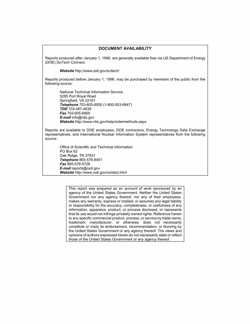
The second example is a recent welding repair application to mitigate the stress corrosion cracking problem facing the nuclear industry. Figure 2 shows a dissimilar metal weld connecting a stainless steel pipe to the nuclear reactor vessel. This dissimilar metal weld requires the use of multiple weld materials to ensure high quality welding. It consists of several hundred weld passes. of weld metal deposited. Full 3D weld simulations would be extremely beneficial to optimize the engineering of this repair weld to control the weld residual stress to prevent stress corrosion cracking. However, today’s industrial modeling capability, in terms of both computational resources and modeling approaches, is simply inadequate for the full 3D simulation. Instead, industry primarily relies on expensive (in the range of $ millions per case) and time consuming (several months to years) experimental weld mockup and residual stress measurements, augmented with simplified approximate modeling analysis, to generate the necessary technical basis for the weld repair of critical nuclear reactor components.
3. STATEMENT OF OBJECTIVES
This HPC4Mfg project was an initial effort aimed at developing and demonstrating the potential of a novel in-house HCP finite element method (FEM) based code specifically designed for broad welding and similar manufacturing processes such as metal additive manufacturing simulation applications. The novelty will include efficient use of computational algorithms and schemes that generally have better scalability on massive parallel HPC systems.
For this initial effort, a measurable technical goal is to demonstrate a substantial increase in computational performance on cluster HPC with 500 to 2000 cores, on the order of 100x compared to workstation-based welding simulations today. This means a reduction of wall clock time of computation for a welding simulation from over 12-15 weeks on today’s workstation computer to less than 24 hours using HPC system and computational codes in this project. To the industry members of the project, such computational performance improvements means that the HPC welding process modeling tools could be realistically utilized to effectively analyze various welding fabrication options/scenarios to minimize dimensional distortion, or proactively mitigate the detrimental impact of welding-induced residual stresses within a timeframe such that expensive and time consuming iterative physical trial and error can be avoided. A secondary objective is, through this research, to identify critical barriers and gaps in HPC codes, that once solved in the future, would lead to further major breakthroughs in application of HPC for welding simulations.
The research and development (R&D) reported herein was sponsored by DOE Office of Energy Efficient and Renewable Energy (EERE), Advanced Manufacturing Office (AMO) under DOE HPC4Mfg Spring 2016 Solicitation. The project is led by General Motors, LLC (GM), with industry partnership of Electric Power Research Institute (EPRI). Oak Ridge National Laboratory (ORNL) is the national lab partner on this project. GM and EPRI represent two major US manufacturing industry sectors (automotive and nuclear energy) where superfast and high-fidelity weld simulation code based on rigorous physics representations of weld process are essential for a broad range of important applications.
4. BENEFITS TO THE FUNDING DOE OFFICE'S MISSION
The proposed HPC based welding modeling tool allows for advanced design of welding fabrication options or scenarios in a practical timeframe. The value added for the industrial team members would be the ability to realistically evaluate welding innovations numerically rather than rely on expensive and time
3
consuming iterative physical trial and error methods. Such a modeling tool would also have significant impact on energy savings, productivity, manufacturing cost reduction, reducing product development cycle, and the overall competitiveness of US welding industry. It will accelerate welding technology development across a broad spectrum of industries from automotive to nuclear energy.
5. TECHNICAL DISCUSSION OF WORK PERFORMED BY ALL PARTIES
GM fabricated Aluminum alloy panel coupons by laser welding under different tooling or constraint conditions. In each coupon, two prototypical automotive body panels were laser brazed together by a welding robot with dual laser beam and filler metal as shown in Figure 1. The material of the panels was Al6111-T4 and filler material was A4047. The four constraint conditions are given as shown in Table 1. General Motors also experimentally measured the distortion of the panel due to welding/brazing for validation of the modeling results. The distortion data of left panel and right panel were measured separately by a non-contact tool 3D scanner. After measurement, samples of weld cross section were mounted to get the bead shape of the laser weld and used for metallurgical observation. The weld bead will provide the basic geometry information and heat input reference for the model.
EPRI provided the detailed information of a round robin weld model including welding condition and bead cross sections. This weld is part of an important US NRC/EPRI collaborative program to address potential stress corrosion cracking problem of dissimilar metal welds in the primary piping loops of the reactor vessel. Due to the size of the problem, only simplified 2-dimensional weld simulations were carried out in the past studies by various modelers. A 3-dimensinal model is created in this program and the essential features and the complexity of the dissimilar metal weld are shown in Figure 2. Fully transient stress analysis for the dissimilar weld of the pipe was carried out by the in-house HPC code developed in this project.
ORNL led the development of the in-house HPC code and performed the calculations of all benchmark examples. The initial development of the in-house code was on a computer equipped with an 8-cores Intel Xeon E5v2 CPU (16 threads) and a Tesla K80 GPU (2 GPU units with 2496 processing cores on each unit) rated at 2.91TFLOPS for peak double precision calculation performance. In addition, the accuracy and performance of the in-house code were compared with commercial software (ABAQUS), on the same computer.
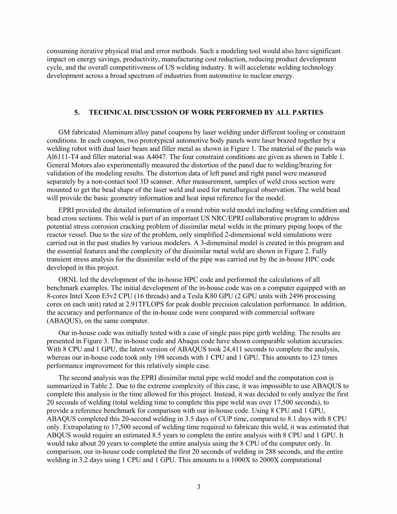
Our in-house code was initially tested with a case of single pass pipe girth welding. The results are presented in Figure 3. The in-house code and Abaqus code have shown comparable solution accuracies. With 8 CPU and 1 GPU, the latest version of ABAQUS took 24,411 seconds to complete the analysis, whereas our in-house code took only 198 seconds with 1 CPU and 1 GPU. This amounts to 123 times performance improvement for this relatively simple case.
The second analysis was the EPRI dissimilar metal pipe weld model and the computation cost is summarized in Table 2. Due to the extreme complexity of this case, it was impossible to use ABAQUS to complete this analysis in the time allowed for this project. Instead, it was decided to only analyze the first 20 seconds of welding (total welding time to complete this pipe weld was over 17,500 seconds), to provide a reference benchmark for comparison with our in-house code. Using 8 CPU and 1 GPU, ABAQUS completed this 20-second welding in 3.5 days of CUP time, compared to 8.1 days with 8 CPU only. Extrapolating to 17,500 second of welding time required to fabricate this weld, it was estimated that ABQUS would require an estimated 8.5 years to complete the entire analysis with 8 CPU and 1 GPU. It would take about 20 years to complete the entire analysis using the 8 CPU of the computer only. In comparison, our in-house code completed the first 20 seconds of welding in 288 seconds, and the entire welding in 3.2 days using 1 CPU and 1 GPU. This amounts to a 1000X to 2000X computational

4
performance improvement. Such a performance improvement was far beyond our own expectations – we originally aimed for an 100X improvement in this 12-month project. Furthermore, our 3D high fidelity model revealed several important details about the weld residual stress distribution that are simply impossible to obtain with the 2-dimensional modeling analysis in the past. As an example, Figure 4 shows the hoop residual stress distribution in both full view and cut view. The residual stress field is clearly non-axisymmetric, which is the fundamental assumption of the 2-dimensional axisymmetric model.
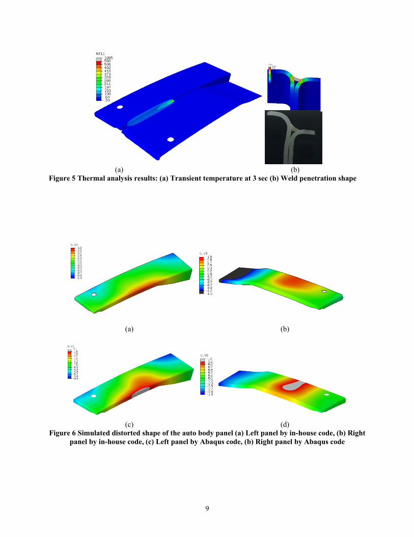
We further extended the in-house HPC code to simulate laser beam weld brazing of relatively large prototypical auto body panel structure provided by GM. The transient temperature and weld nugget penetration shape predicted by the model are presented in Figure 5, which shows good agreement with the actual weld nugget shown in the same figure for comparison. Transient thermal stress analyses were carried out by the in-house code on the same Tesla K80 GPU workstation. For each case, the computation time by the in-house code was less than 2 hours. For benchmarking, ABAUS was used to run one case (Case 1) which took approximately 152 hours, representing over 70X speed improvement. The out-of-plane distortion of left panel and right panel were plotted in Figure 6. The predicted welding distortion by the in-house code and ABAQUS code has overall good agreement in distortion magnitude and mode.
6. SUBJECT INVENTIONS (AS DEFINED IN THE CRADA)
The in-house code and certain novel computational schemes and algorithms developed in this project are considered for IP protection, and thereby not disclosed in this report.
7. COMMERCIALIZATION POSSIBILITIES
The in-house FEM code with innovative solution scheme developed in this project represents a major breakthrough in speeding up of welding simulation and additive manufacturing processes that are fundamentally a welding process. It is expected that it will be transferred and applied by the industry participants in the project. It also has generated significant interest for potential licensing to major commercial software companies.
8. PLANS FOR FUTURE COLLABORATION
ORNL will continue to work on the large-scale modeling of several highly demanding weld repair and fabrications problems in the nuclear industry, in partnership with EPRI. Tentative targeting problems include advanced welding technology development for welding of highly irradiated reactor internals. EPRI has several other applications with residual stress measurement data. The modeled results and measured ones will be compared together for further developing the in-house code with continued improvement in accuracy and efficiency of the high-performance computing tool in solving practical ultra-large-scale welding problems.
ORNL will also work closely with General Motors to optimize the welding and clamping conditions to minimize the panel distortion. Currently the computational cost has been drastically reduced to a

5
reasonable level, and the accuracy is confirmed by comparison with commercial software. The teams are refining the model details such clamping, initial deformation and stress, and the way of comparison between simulation and measurement.
9. CONCLUSIONS
This 12-month HPC4Mfg project has produced an initial version of in-house FEM code that resulted in a breakthrough in computational speed for welding and additive manufacturing simulations. Through innovations in computational algorithms and schemes, the in-house code makes it possible to simulate the highly non-linear transient thermal-metallurgical-mechanical process in welding based on rigorous physics representations of weld process without unnecessary over-simplifications.
The accuracy of the in-house HPC code has been confirmed by a benchmark study on a pipe girth weld. The computation time in a large-diameter and multi-pass welding analysis was reduced from years to days by application of the in-house code while keeping confidence in solution accuracy. Computational time for simulations of laser welding of auto-body components was reduced from about a week to approximately 2 hours. This is a truly remarkable breakthrough in the residual stress analysis of evolving thermal-mechanical processes including welding and additive manufacturing.

6
Table 1 Definition of welding cases under different clamping
Clamping left side panel Clamping right side panel
Case 1 Two ends \
Case 2 \ Two ends
Case 3 Two ends Two ends
Case 4 Top ends Top ends
(a) (b)
Figure 1 Laser beam welding of panel structure: (a) laser beam configuration (b) fixture setup
7
Figure 2 Welding pass layout for the EPRI round robin model
(a)
(b)
Figure 3 Comparison of simulation results between ABAQUS and in-house codes: (a) Mises stress
(b) Equivalent plastic strain

8
Table 2 Comparison of time cost by the two codes
Figure 4 Computed hoop stress in full view and cut view
Table 3 Computational performance in simulation of the large dissimilar weld.
Software Abaqus standard In-house code
Platform 8 CPU threads 8 CPU threads + 1 GPU 1 CPU + 1GPU
Trial analysis-20 s welding 8.1 days 3.5 days 388 sec
Full pass analysis 19.6 years 8.5 years 3.2 days
Speedup factor Ref 2200X
Speedup factor Ref 1000X
Abaqus code (CPU mode) Abaqus code
In-house code
No. CPU threads
1 4 8 12 16 8 CPU+1 GPU
1 CPU+1 GPU
Time (s) 120,099 41,413 28,595 25,552 22,660 24,411 198
Speedup ref. 2.9 4.2 4.7 5.3 4.9 606.6
Speedup 0.24 0.69 ref. 1.12 1.26 1.17 144.4
9
(a) (b)
Figure 5 Thermal analysis results: (a) Transient temperature at 3 sec (b) Weld penetration shape
(a) (b)
(c) (d)
Figure 6 Simulated distorted shape of the auto body panel (a) Left panel by in-house code, (b) Right panel by in-house code, (c) Left panel by Abaqus code, (b) Right panel by Abaqus code