Embed Size (px)
Citation preview
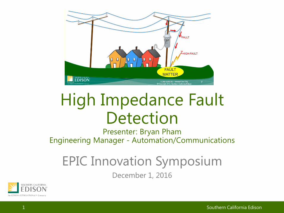
High Impedance Fault Detection
Presenter: Bryan Pham Engineering Manager - Automation/Communications
EPIC Innovation Symposium December 1, 2016
Southern California Edison 1

Problem Statement
• Overhead distribution circuit conductor can break and fall to the ground due to car hit pole, high winds, or splice failure, etc.
• High impedance faults occur when fallen conductor touches high resistance surface (e.g., asphalt, concrete, sand, rocks, etc.). The high impedance faults do not generate high enough current to trip traditional protection devices (i.e., substation circuit breaker, automatic recloser, and fuses).
• As a result, many distribution power lines are still energized when an SCE employee (e.g., a troubleman) arrives at the scene of down-wire.
• The energized wire laying on the ground poses serious public safety risk and can be fatal for anyone touching it by accident.
2
Proprietary and Confidential Southwest Research Institute and Southern California Edison
Load
Source

Objective Demonstrates an innovative approach to improve public safety by detecting wiredown on high impedance surface (asphalt, concrete, sand, etc.). Develop an anomaly detection system using Spread-Spectrum Time-Domain Reflectometry (SSTDR) techniques that can identify anomaly (high) impedances on electrical distribution lines and determine where they are occurring.
3
Proprietary and Confidential Southwest Research Institute and Southern California Edison
System Concept Overview Spread Spectrum Time Domain Reflectometry (SSTDR) Concept: • A radar signal, operating at frequencies between 2MHz –
40MHz is injected into the line at a known starting point • The signal will reflect back to the origin wherever it hits an
impedance mismatch • Reflections are mapped to a known “good” map, where the
system can now look for reflections that don’t map to a known object
• Maintain 0.02% distance accuracy • The system looks for impedance mismatches that aren’t a
part of the normal line construction.
4
Proprietary and Confidential Southwest Research Institute and Southern California Edison

System Concept Overview
Proprietary and Confidential Southwest Research Institute and Southern California Edison 5
Capture a reflection sequence of the circuit when it does not have any anomaly (high) impedance conditions and correlate that to a GIS map of the circuit
Regularly send signals down the line and compare these reflections to the reflection map to look for anomalies
Determine and report the location of the anomaly for a truck roll

Concept
Proprietary and Confidential Southwest Research Institute and Southern California Edison
6
• Assume this represents a known “good” map of the circuit
• A series of signals is injected into the line and the reflections are captured
• All reflection points are mapped to the “good” map
Concept
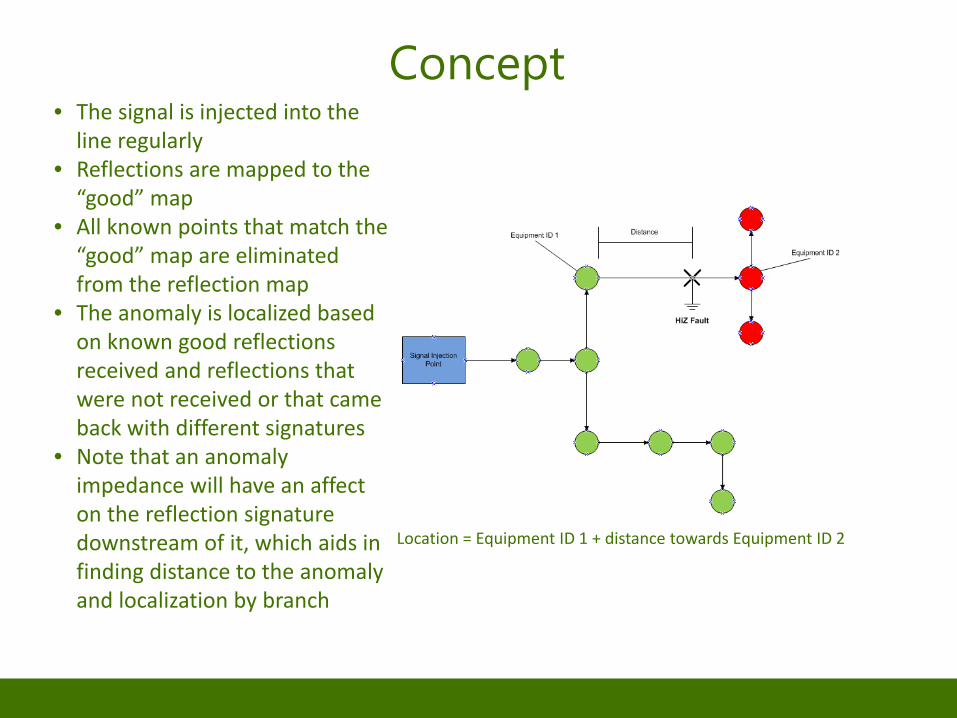
Location = Equipment ID 1 + distance towards Equipment ID 2
Proprietary and Confidential Southwest Research Institute and Southern California Edison 7
• The signal is injected into the line regularly
• Reflections are mapped to the “good” map
• All known points that match the “good” map are eliminated from the reflection map
• The anomaly is localized based on known good reflections received and reflections that were not received or that came back with different signatures
• Note that an anomaly impedance will have an affect on the reflection signature downstream of it, which aids in finding distance to the anomaly and localization by branch

Equipment Demonstration & Evaluation Facility
• Located in Shawnee sub – 66/12kV
• Test circuit: BRAVES • Dedicated circuit breaker for test
circuit – In addition various circuit protection
• Two circuit sections • Overhead and underground line • Equipment:
– Automatic Reclosers (ARs) – RAG Switches – Load Banks – Capacitor Banks – Grid simulators – 2MW Battery

EDEF’s First Test on 4/25/2016: High Impedance Fault Detection
• Conductor on the ground
Project Schedule
• Phase 1: (2014) Demonstrate the feasibility of technology, mathematics, and applied physics to solve the project objective.
• Phase 2: (2015-2017) Development of solution, including software algorithms, detections hardware, and systems integration. Prototype field testing and demonstration at Chino Test Circuit; and, energized circuit testing at Shawnee Substation’s test facility. Also includes production circuit pilot.
• Phase 3: (2018) Provide Solution for deployment.
10 Proprietary and Confidential
Southwest Research Institute and Southern California Edison

Next Step Activities – 2017 • Continue demonstration of SSTDR to detect anomaly (high)
impedances on distribution lines ‒ Determine distance and branching limits ‒ Demonstrate effective signal amplification and noise reduction
techniques ‒ Evaluate effects of equipment on line ‒ Develop mapping strategy ‒ Develop Prototype for production
• Field test on actual lines at test sites Activities – 2018 • Field Pilot on several distribution circuits • Provide solution for deployment
Proprietary and Confidential Southwest Research Institute and Southern California Edison 11

QUESTIONS?
12


![Enhance High Impedance Fault Detection and …yweng2/papers/2019TSG-PMU.pdfalgorithm [2], impedance-based method [3] and PC-based fault locating and diagnosis algorithm [4], etc. However,](https://img.dokumen.tips/doc/110x75/5fe122d4df236711b2274e10/enhance-high-impedance-fault-detection-and-yweng2papers2019tsg-pmupdf-algorithm.jpg)