Embed Size (px)
Citation preview

® SPECIF ICAT ION SUBMITTAL Page
Job Name:
Job Number:
Model Numbers:
LED Dimming Driver Hi-lume® A-Series LTE Architectural Dimming
369543d 1 07.08.14
Hi-lume® A-Series, case type K
3.00 in (76 mm) W x 1.00 in (25 mm) H x 4.90 in (124 mm) L
Hi-lume® A-Series, case type M
1.18 in (30 mm) W x 1.00 in (25 mm) H x 14.25 in (362 mm) L
Hi-lume® A-Series Driver Overview Forward-Phase Control
Hi-lume® A-Series Driver is a high-performance LED driver that provides smooth, continuous 1% dimming for virtually any LED fixture, whether it requires constant-current or constant-voltage. It is the most versatile LED driver offered today due to its compatibility with a wide variety of LED arrays, multiple form factors, and numerous control options.
Features
• Continuous, flicker-free dimming from 100% to 1%.
• Guaranteed compatibility with selected Maestro Wireless®, RadioRA® 2, HomeWorks® QS, GRAFIK Eye® QS, GRAFIK Systems™, Quantum®, and Stanza® dimmers. Please see the chart at the end of this document or contact Lutron for details regarding compatible controls.
• 100% performance tested at factory.
• 100% burned in at factory.
• A rated lifetime of 50,000 hours @ tc =149 °F (65 °C).
• UL recognized for United States and Canada.
• FCC Part 15 compliant for commercial and residential applications at 120 V ~.
• Pulse width modulation (PWM) or constant-current reduction (CCR) dimming methods available. See Application Note #360 for details.
• RoHS Compliant
• For more information please go to: www.lutron.com/HilumeLED
NN/C
DLN/C
N/C
WARNING: Shock hazard. May result in serious injury or death. Disconnect powerbefore servicing or installing.
ADVERTISSEMENT: Danger d’èlectrocution. Peut causer de graves lèsions ou dècès de la personne. Couper l’alimentation au disjoncteur avant de procèder au montage ou à l’entretien de l’installation.
LTEA4U1UMN-HC070
0 27557 00196 0
120 V0,70 A MaxClass 20,27 A
Input Entrèe
32 W Max
50 / 60 Hz
Output Sortie38,0 V Max
•DLHi-lume®
A-Series +V
-V •N
t c
Solid 18 - 16 AWG (0.75 - 1.5 mm2) wire only. Utiliser un fil solide 18 - 16 AWG (0,75 - 1,5 mm2)seulement.
Cu Al 5/16 in.(8 mm)
lutron.com N/C
N/C
N/C
N/C
+V-V
Hi-lume® A-Series1% Dimming LED Driver1% Pilote de DEL
Ver. A
Suitable for damp locations. Pour les endroits emplacements.
To remove wire, insert screw driver into slot. Pour enlever le fil, insérez un tourneviz dansla fente.
Warranty void if unit opened.Garantie annulée si ouvert.
Pats. / Brevets: 7,911,156; 8,466,628; 8,492,987; 8,492,988USA / Canada 1.800.523.9466 P
/N 5
0015
684

® SPECIF ICAT ION SUBMITTAL Page
Job Name:
Job Number:
Model Numbers:
LED Dimming Driver Hi-lume® A-Series LTE Architectural Dimming
369543d 2 07.08.14
Specifications
Performance
• Dimming Range: 100% to 1%
• Operating Voltage: 120 V ~ at 50/60 Hz (Forward Phase Control)
• A rated lifetime of 50,000 hours @ tc = 149 °F (65 °C). Contact Lutron for derating information.
• Patented thermal foldback protection
• LEDs turn on to any dimmed level without going to full brightness.
• Nonvolatile memory restores all driver settings after power failure.
• Power Factor: > 0.90 at 40 W
• Total Harmonic Distortion (THD): < 20% at 40 W
• Inrush Current: < 2 A
• Inrush Current Limiting Circuitry: eliminates circuit breaker tripping, switch arcing and relay failure.
• Open circuit protected
• Short circuit protected
• Turn-on time: ≤ 1 second
• PWM Dimming Frequency: 550 Hz
Environmental
• Sound Rating: Class A.
• Relative Humidity: Maximum 90% non-condensing.
• Minimum operating ambient temperature (ta) = 32 °F (0 °C).
Regulatory Approvals
• Meets ANSI C62.41 category A surge protection standards up to and including 4 kV.
• FCC Part 15 compliant for commercial and residential applications.
• Manufacturing facilities employ ESD reduction practices that comply with the requirements of ANSI/ESD S20.20.
• Lutron® Quality Systems registered to ISO 9001.2008.
Wire GaugeMaximum Lead Length
200 mA to 700 mA
710 mA to 1.50 A
1.51 A to 2.10 A
18 AWG (0.75 mm2) 30 ft (9 m) 15 ft (4.5 m) 10 ft (3 m)
16 AWG (1.5 mm2) 35 ft (10.5 m) 25 ft (7.5 m) 15 ft (4.5 m)
14 AWG (2.5 mm2) 50 ft (15 m) 40 ft (12 m) 25 ft (7.5 m)
12 AWG (4.0 mm2) 100 ft (30 m) 60 ft (18 m) 40 ft (12 m)
Wire GaugeMaximum Lead Length
10 to 20 V- 20.5 to 40 V- 40.5 to 60 V-
18 AWG (0.75 mm2) 10 ft (3 m) 15 ft (4.5 m) 30 ft (9 m)
16 AWG (1.5 mm2) 15 ft (4.5 m) 25 ft (7.5 m) 50 ft (15 m)
14 AWG (2.5 mm2) 25 ft (7.5 m) 40 ft (12 m) 75 ft (22.5 m)
12 AWG (4.0 mm2) 40 ft (12 m) 60 ft (18 m) 100 ft (30 m)
• UL 8750 recognized.
• Class 2 output available.
• Models available to meet LED Driver requirements for Energy Star 1.1.
Driver Wiring & Mounting
• Driver is grounded by a mounting screw to the grounded fixture (or by terminal connection on the K case).
• Terminal blocks on the driver accept one solid wire per terminal from 18 AWG to 16 AWG (0.75 mm( to 1.5 mm().
• Fixture must be grounded in accordance with local and national electrical codes.
• Maximum driver-to-LED light engine wire length for Constant-Current Drivers:
• Maximum driver-to-LED light engine wire length for Constant-Voltage Drivers:

® SPECIF ICAT ION SUBMITTAL Page
Job Name:
Job Number:
Model Numbers:
LED Dimming Driver Hi-lume® A-Series LTE Architectural Dimming
369543d 3 07.08.14
How to Build a Model Number: Hi-lume® A-Series
LTEA4U1U _ _ - _ _ _ _ _
Case Style:
S = Studded (K case only)
N = Non-StuddedDriver Output:
C = Constant-current driver with pulse width modulation (PWM) dimming
A = Constant-current driver with constant-current reduction (CCR) dimming
V = Constant-voltage driver with pulse width modulation (PWM) dimming
Current Level (for Constant-Current):020 = 0.20 A; 021 = 0.21 A…070 = 0.70 A…210 = 2.10 A
Voltage Level (for Constant-Voltage):100 = 10.0 V; 105 = 10.5 V…600 = 60.0 V
Case Size:
K = Compact
M = Stick
example: LTEA4U1UKS-HC070For further assistance selecting your model number, contact our LED Center of Excellence at 1.877.346.5338 or [email protected]
Class 2 Constant-Voltage
A = 10.0 V–12.0 V
B = 12.5 V–20.0 V
C = 20.5 V–24.0 V
D = 24.5 V–38.0 V
Isolated Non-Class 2 Constant-Voltage
X = 38.5 V–60.0 V
Class 2 Constant-Current
E = 0.20 A–0.50 A 30 V–54 V
F = 0.51 A–1.00 A 30 V–54 V
G = 0.20 A–0.70 A 8 V–20 V
H = 0.20 A–0.70 A 15 V–38 V
I = 0.71 A–1.05 A 8 V–20 V
J = 0.71 A–1.05 A 15 V–38 V
K = 1.06 A–1.50 A 8 V–20 V
L = 1.06 A–1.50 A 15 V–38 V
M = 1.51 A–2.10 A 8 V – 20 V
Isolated Non-Class 2 Constant-Current
Y = 0.20 A–0.50 A 30 V–60 V
Z = 0.51 A–1.00 A 30 V–60 V
LED Load Output Range (see the following pages for more detail):

® SPECIF ICAT ION SUBMITTAL Page
Job Name:
Job Number:
Model Numbers:
LED Dimming Driver Hi-lume® A-Series LTE Architectural Dimming
369543d 4 07.08.14
“A” Output Range, Voltage Driver Models
Output Current vs. Output Voltage
0
0.5
1
1.5
2
2.5
3
3.5
0 10 20 30 40 50 60
Output Voltage (V)
Out
put
Cur
rent
(A)
12
Output Power vs. Output Voltage
0
5
10
15
20
25
30
35
40
0 10 20 30 40 50 60
Output Voltage (V)
Out
put
Po
wer
(W)
12
60
65
70
75
80
85
90
5 10 15 20 25 30 35 40
Output Power (W)
Effi
cien
cy (%
)
Driver Efficiency vs. Output Power at 120 V~
A
5 W Min.
A
3.3 A Max.
3.3
10.0 V12.0 V
Voltage Driver Operation Range:
Typical Performance Specifications:
Output Current vs. Output Voltage
0
0.5
1
1.5
2
2.5
3
3.5
0 10 20 30 40 50 60
Output Voltage (V)
Out
put
Cur
rent
(A)
12
Output Power vs. Output Voltage
0
5
10
15
20
25
30
35
40
0 10 20 30 40 50 60
Output Voltage (V)
Out
put
Po
wer
(W)
12
60
65
70
75
80
85
90
5 10 15 20 25 30 35 40
Output Power (W)
Effi
cien
cy (%
)
Driver Efficiency vs. Output Power at 120 V~
A
5 W Min.
A
3.3 A Max.
3.3
10.0 V12.0 V
Parameter Value Test Conditions
Input Current 400 mA ta = 25 °C, 12.0 V 40 W load, Max. Light Output, K enclosure 120 V~ without a dimmer
Power Factor 0.98
THD 16%
Driver Efficiency 79%
Driver Type Output Dimming Method Output Voltage Output Current Output Power Standards Recognition
Constant-Voltage Driver (Class 2)
Pulse Width Modulation (PWM) 10.0 – 12.0 V PWM 0.42 – 3.3 A 5 – 40 W

® SPECIF ICAT ION SUBMITTAL Page
Job Name:
Job Number:
Model Numbers:
LED Dimming Driver Hi-lume® A-Series LTE Architectural Dimming
369543d 5 07.08.14
“B” Output Range, Voltage Driver Models
Output Current vs. Output Voltage
0
0.5
1
1.5
2
2.5
3
3.5
0 10 20 30 40 50 60
Output Voltage (V)
Out
put
Cur
rent
(A)
12.5
Output Power vs. Output Voltage
0
5
10
15
20
25
30
35
40
0 10 20 30 40 50 60
Output Voltage (V)
Out
put
Po
wer
(W)
12.5
60
65
70
75
80
85
90
5 10 15 20 25 30 35 40
Output Power (W)
Effi
cien
cy (%
)
Driver Efficiency vs. Output Power at 120 V~
B
40 W Max.
B
5 W Min.
20.0 V
18.0 V
12.5 V
Voltage Driver Operation Range:
Typical Performance Specifications:
Output Current vs. Output Voltage
0
0.5
1
1.5
2
2.5
3
3.5
0 10 20 30 40 50 60
Output Voltage (V)
Out
put
Cur
rent
(A)
12.5
Output Power vs. Output Voltage
0
5
10
15
20
25
30
35
40
0 10 20 30 40 50 60
Output Voltage (V)
Out
put
Po
wer
(W)
12.5
60
65
70
75
80
85
90
5 10 15 20 25 30 35 40
Output Power (W)
Effi
cien
cy (%
)
Driver Efficiency vs. Output Power at 120 V~
B
40 W Max.
B
5 W Min.
20.0 V
18.0 V
12.5 V
Parameter Value Test Conditions
Input Current 400 mA ta = 25 °C, 20.0 V 40 W load, Max. Light Output, K enclosure 120 V~ without a dimmer
Power Factor 0.99
THD 9%
Driver Efficiency 83%
Driver Type Output Dimming Method Output Voltage Output Current Output Power Standards Recognition
Constant-Voltage Driver (Class 2)
Pulse Width Modulation (PWM) 12.5 – 20.0 V PWM 0.25 – 3.2 A 5 – 40 W

® SPECIF ICAT ION SUBMITTAL Page
Job Name:
Job Number:
Model Numbers:
LED Dimming Driver Hi-lume® A-Series LTE Architectural Dimming
369543d 6 07.08.14
“C” Output Range, Voltage Driver Models
Output Current vs. Output Voltage
0
0.5
1
1.5
2
2.5
3
3.5
0 10 20.5 30 40 50 60
Output Voltage (V)
Out
put
Cur
rent
(A)
Output Power vs. Output Voltage
0
5
10
15
20
25
30
35
40
0 10 20.5 30 40 50 60
Output Voltage (V)
Out
put
Po
wer
(W)
60
65
70
75
80
85
90
5 10 15 20 25 30 35 40
Output Power (W)
Effi
cien
cy (%
)
24 24
Driver Efficiency vs. Output Power at 120 V~
C
40 W Max.
5 W Min.
C
24 V
20.5 V
Voltage Driver Operation Range:
Typical Performance Specifications:
Output Current vs. Output Voltage
0
0.5
1
1.5
2
2.5
3
3.5
0 10 20.5 30 40 50 60
Output Voltage (V)
Out
put
Cur
rent
(A)
Output Power vs. Output Voltage
0
5
10
15
20
25
30
35
40
0 10 20.5 30 40 50 60
Output Voltage (V)
Out
put
Po
wer
(W)
60
65
70
75
80
85
90
5 10 15 20 25 30 35 40
Output Power (W)
Effi
cien
cy (%
)
24 24
Driver Efficiency vs. Output Power at 120 V~
C
40 W Max.
5 W Min.
C
24 V
20.5 V
Parameter Value Test Conditions
Input Current 380 mA ta = 25 °C, 24.0 V 40 W load, Max. Light Output, K enclosure 120 V~ without a dimmer
Power Factor 0.99
THD 10%
Driver Efficiency 84%
Driver Type Output Dimming Method Output Voltage Output Current Output Power Standards Recognition
Constant-Voltage Driver (Class 2)
Pulse Width Modulation (PWM) 20.5 – 24.0 V PWM 1.95 – 0.21 A 5 – 40 W

® SPECIF ICAT ION SUBMITTAL Page
Job Name:
Job Number:
Model Numbers:
LED Dimming Driver Hi-lume® A-Series LTE Architectural Dimming
369543d 7 07.08.14
Driver Type Output Dimming Method Output Voltage Output Current Output Power Standards Recognition
Constant-Voltage Driver (Class 2)
Pulse Width Modulation (PWM) 24.5 – 38.0 V PWM 0.13 – 1.63 A 5 – 40 W
“D” Output Range, Voltage Driver Models
Output Current vs. Output Voltage
0
0.5
1
1.5
2
2.5
3
3.5
0 10 20 30 40 50 60
Output Voltage (V)
Out
put
Cur
rent
(A)
Output Power vs. Output Voltage
0
5
10
15
20
25
30
35
40
0 10 20 30 40 50 60
Output Voltage (V)
Out
put
Po
wer
(W)
60
65
70
75
80
85
90
5 10 15 20 25 30 35 40
Output Power (W)
Effi
cien
cy (%
)
24.5 24.5 3838
Driver Efficiency vs. Output Power at 120 V~
40 W Max.
5 W Min.
D
D
24.5 V
36 V 38 V
Voltage Driver Operation Range:
Typical Performance Specifications:
Output Current vs. Output Voltage
0
0.5
1
1.5
2
2.5
3
3.5
0 10 20 30 40 50 60
Output Voltage (V)
Out
put
Cur
rent
(A)
Output Power vs. Output Voltage
0
5
10
15
20
25
30
35
40
0 10 20 30 40 50 60
Output Voltage (V)
Out
put
Po
wer
(W)
60
65
70
75
80
85
90
5 10 15 20 25 30 35 40
Output Power (W)
Effi
cien
cy (%
)
24.5 24.5 3838
Driver Efficiency vs. Output Power at 120 V~
40 W Max.
5 W Min.
D
D
24.5 V
36 V 38 V
Parameter Value Test Conditions
Input Current 380 mA ta = 25 °C, 38.0 V 40 W load, Max. Light Output, K enclosure 120 V~ without a dimmer
Power Factor 0.99
THD 7%
Driver Efficiency 86%

® SPECIF ICAT ION SUBMITTAL Page
Job Name:
Job Number:
Model Numbers:
LED Dimming Driver Hi-lume® A-Series LTE Architectural Dimming
369543d 8 07.08.14
Driver Type Output Dimming Method Output Voltage Output Current Output Power Standards Recognition
Constant-Current Driver (Class 2)
Constant-Current Reduction (CCR) 30 – 54 V- 0.20 – 0.50 A 6 – 27 W
“E” Output Range, Current Driver Models
Output Voltage vs. Output Current
Output Current (A)
Out
put
Vo
ltag
e (V
)
Output Power vs. Output Current
Output Current (A)
Out
put
Po
wer
(W)
0
10
20
30
40
50
54
60
0.20 0.50 0.20 0.500
5
10
15
20
25
30
35
40
0 0.35 0.7 1.05 1.4 1.75 2.1
60
65
70
75
80
85
90
Output Power (W)
Effi
cien
cy (%
)
6 9 12 15 18 21 24 27
0 0.35 0.7 1.41.05 2.1
Driver Efficiency vs. Output Power at 120 V~
E
30 V Min.
54 V Max.
E
0.20 A
0.35 A
0.50 A
Current Driver Operation Range:
Typical Performance Specifications:
Output Voltage vs. Output Current
Output Current (A)
Out
put
Vo
ltag
e (V
)
Output Power vs. Output Current
Output Current (A)
Out
put
Po
wer
(W)
0
10
20
30
40
50
54
60
0.20 0.50 0.20 0.500
5
10
15
20
25
30
35
40
0 0.35 0.7 1.05 1.4 1.75 2.1
60
65
70
75
80
85
90
Output Power (W)
Effi
cien
cy (%
)
6 9 12 15 18 21 24 27
0 0.35 0.7 1.41.05 2.1
Driver Efficiency vs. Output Power at 120 V~
E
30 V Min.
54 V Max.
E
0.20 A
0.35 A
0.50 A
Parameter Value Test Conditions
Input Current 270 mA ta = 25 °C, 0.50 A 27 W load, Max. Light Output, K enclosure 120 V~ without a dimmer
Power Factor 0.99
THD 10%
Driver Efficiency 83%
® SPECIF ICAT ION SUBMITTAL Page
Job Name:
Job Number:
Model Numbers:
LED Dimming Driver Hi-lume® A-Series LTE Architectural Dimming
369543d 9 07.08.14
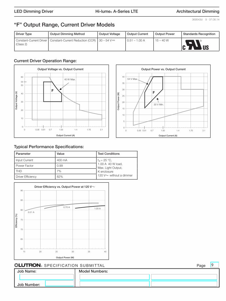
Driver Type Output Dimming Method Output Voltage Output Current Output Power Standards Recognition
Constant-Current Driver (Class 2)
Constant-Current Reduction (CCR) 30 – 54 V- 0.51 – 1.00 A 15 – 40 W
“F” Output Range, Current Driver Models
Output Voltage vs. Output Current
Output Current (A)
Out
put
Vo
ltag
e (V
)
Output Power vs. Output Current
Output Current (A)
Out
put
Po
wer
(W)
0
10
20
30
40
50
60
0 0.51 0.510
5
10
15
20
25
30
35
40
0 0.35 0.7 1.00 1.4 1.75 2.1
54
0.35 0.7 1.4 1.75 2.11.00
Output Power (W)
Effi
cien
cy (%
)
60
65
70
75
80
85
90
15 20 25 30 35 40
Driver Efficiency vs. Output Power at 120 V~
40 W Max.
F
30 V Min.
54 V Max.
F
0.51 A
0.70 A 1.00 A
Current Driver Operation Range:
Typical Performance Specifications:
Output Voltage vs. Output Current
Output Current (A)
Out
put
Vo
ltag
e (V
)
Output Power vs. Output Current
Output Current (A)
Out
put
Po
wer
(W)
0
10
20
30
40
50
60
0 0.51 0.510
5
10
15
20
25
30
35
40
0 0.35 0.7 1.00 1.4 1.75 2.1
54
0.35 0.7 1.4 1.75 2.11.00
Output Power (W)
Effi
cien
cy (%
)
60
65
70
75
80
85
90
15 20 25 30 35 40
Driver Efficiency vs. Output Power at 120 V~
40 W Max.
F
30 V Min.
54 V Max.
F
0.51 A
0.70 A 1.00 A
Parameter Value Test Conditions
Input Current 400 mA ta = 25 °C, 1.00 A 40 W load, Max. Light Output, K enclosure 120 V~ without a dimmer
Power Factor 0.99
THD 7%
Driver Efficiency 82%

® SPECIF ICAT ION SUBMITTAL Page
Job Name:
Job Number:
Model Numbers:
LED Dimming Driver Hi-lume® A-Series LTE Architectural Dimming
369543d 10 07.08.14
“G” Output Range, Current Driver Models
Output Voltage vs. Output Current
Output Current (A)
Out
put
Vo
ltag
e (V
)
Output Power vs. Output Current
Output Current (A)
Out
put
Po
wer
(W)
0
10
20
30
40
50
60
0
5
10
15
20
25
30
35
40
0 0.35 0.7 1.05 1.4 1.75 2.1
Output Power (W)
Effi
cien
cy (%
)
8
0.20
2 4 6 8 10 12 14
0.35 0.7 1.4 1.75 2.11.050.20
45
50
55
60
65
70
75
80
Driver Efficiency vs. Output Power at 120 V~
G
8 V Min.
20 V Max.
G
0.20 A
0.35 A
0.50 A
0.70 A
Current Driver Operation Range:
Typical Performance Specifications:
Driver Type Output Dimming Method Output Voltage Output Current Output Power Standards Recognition
Constant-Current Driver (Class 2)
Pulse Width Modulation (PWM) 8 – 20 V PWM 0.20 – 0.70 A 2 – 14 W
Constant-Current Reduction (CCR) 8 – 20 V-
Output Voltage vs. Output Current
Output Current (A)
Out
put
Vo
ltag
e (V
)
Output Power vs. Output Current
Output Current (A)
Out
put
Po
wer
(W)
0
10
20
30
40
50
60
0
5
10
15
20
25
30
35
40
0 0.35 0.7 1.05 1.4 1.75 2.1
Output Power (W)
Effi
cien
cy (%
)
8
0.20
2 4 6 8 10 12 14
0.35 0.7 1.4 1.75 2.11.050.20
45
50
55
60
65
70
75
80
Driver Efficiency vs. Output Power at 120 V~
G
8 V Min.
20 V Max.
G
0.20 A
0.35 A
0.50 A
0.70 A
Parameter Value Test Conditions
Input Current 150 mA ta = 25 °C, 0.70 A 14 W load, Max. Light Output, K enclosure 120 V~ without a dimmer
Power Factor 0.99
THD 12%
Driver Efficiency 76%

® SPECIF ICAT ION SUBMITTAL Page
Job Name:
Job Number:
Model Numbers:
LED Dimming Driver Hi-lume® A-Series LTE Architectural Dimming
369543d 11 07.08.14
“H” Output Range, Current Driver Models
Output Voltage vs. Output Current
Output Current (A)
Out
put
Vo
ltag
e (V
)
Output Power vs. Output Current
Output Current (A)
Out
put
Po
wer
(W)
0
10
20
30
40
50
60
0 0.35 0.7 1.4 1.75 2.10
5
10
15
20
25
30
35
40
Output Power (W)
Effi
cien
cy (%
)
1.05
15
38
0.20 0 0.35 0.7 1.4 1.75 2.11.050.20
60
65
70
75
80
85
90
3 8 13 18 23
Driver Efficiency vs. Output Power at 120 V~
H
15 V Min.
38 V Max.
H
0.20 A
0.35 A
0.50 A0.70 A
Current Driver Operation Range:
Typical Performance Specifications:
Output Voltage vs. Output Current
Output Current (A)
Out
put
Vo
ltag
e (V
)
Output Power vs. Output Current
Output Current (A)
Out
put
Po
wer
(W)
0
10
20
30
40
50
60
0 0.35 0.7 1.4 1.75 2.10
5
10
15
20
25
30
35
40
Output Power (W)
Effi
cien
cy (%
)
1.05
15
38
0.20 0 0.35 0.7 1.4 1.75 2.11.050.20
60
65
70
75
80
85
90
3 8 13 18 23
Driver Efficiency vs. Output Power at 120 V~
H
15 V Min.
38 V Max.
H
0.20 A
0.35 A
0.50 A0.70 A
Parameter Value Test Conditions
Input Current 270 mA ta = 25 °C, 0.70 A 26 W load, Max. Light Output, K enclosure 120 V~ without a dimmer
Power Factor 0.99
THD 8%
Driver Efficiency 83%
Driver Type Output Dimming Method Output Voltage Output Current Output Power Standards Recognition
Constant-Current Driver (Class 2)
Pulse Width Modulation (PWM) 15 – 38 V PWM 0.20 – 0.70 A 3 – 26 W
Constant-Current Reduction (CCR) 15 – 38 V-

® SPECIF ICAT ION SUBMITTAL Page
Job Name:
Job Number:
Model Numbers:
LED Dimming Driver Hi-lume® A-Series LTE Architectural Dimming
369543d 12 07.08.14
“I” Output Range, Current Driver Models
Output Voltage vs. Output Current
Output Current (A)
Out
put
Vo
ltag
e (V
)
Output Power vs. Output Current
Output Current (A)
Out
put
Po
wer
(W)
0
10
20
30
40
50
60
0
5
10
15
20
25
30
35
40
0 0.35 0.7 1.05 1.4 1.75 2.10.200 0.35 0.71 1.4 1.751.05 2.1
8
Output Power (W)
Effi
cien
cy (%
)
60
65
70
75
80
85
90
6 9 12 15 18 21
Driver Efficiency vs. Output Power at 120 V~
I
8 V Min.
20 V Max.
I
0.71 A 1.05 A
Current Driver Operation Range:
Typical Performance Specifications:
Output Voltage vs. Output Current
Output Current (A)
Out
put
Vo
ltag
e (V
)
Output Power vs. Output Current
Output Current (A)
Out
put
Po
wer
(W)
0
10
20
30
40
50
60
0
5
10
15
20
25
30
35
40
0 0.35 0.7 1.05 1.4 1.75 2.10.200 0.35 0.71 1.4 1.751.05 2.1
8
Output Power (W)
Effi
cien
cy (%
)
60
65
70
75
80
85
90
6 9 12 15 18 21
Driver Efficiency vs. Output Power at 120 V~
I
8 V Min.
20 V Max.
I
0.71 A 1.05 A
Parameter Value Test Conditions
Input Current 220 mA ta = 25 °C, 1.05 A 21 W load, Max. Light Output, K enclosure 120 V~ without a dimmer
Power Factor 0.99
THD 11%
Driver Efficiency 79%
Driver Type Output Dimming Method Output Voltage Output Current Output Power Standards Recognition
Constant-Current Driver (Class 2)
Pulse Width Modulation (PWM) 8 – 20 V PWM 0.71 – 1.05 A 6 – 21 W
Constant-Current Reduction (CCR) 8 – 20 V-

® SPECIF ICAT ION SUBMITTAL Page
Job Name:
Job Number:
Model Numbers:
LED Dimming Driver Hi-lume® A-Series LTE Architectural Dimming
369543d 13 07.08.14
“J” Output Range, Current Driver Models
Output Voltage vs. Output Current
Output Current (A)
Out
put
Vo
ltag
e (V
)
Output Power vs. Output Current
Output Current (A)
Out
put
Po
wer
(W)
0
10
20
30
40
50
60
0
5
10
15
20
25
30
35
40
0 0.35 0.71 1.05 1.4 1.75 2.1
15
38
0 0.35 1.05 1.4 1.75 2.10.71
Output Power (W)
Effi
cien
cy (%
)
60
65
70
75
80
85
90
10 15 20 25 30 35 40
Driver Efficiency vs. Output Power at 120 V~
J
15 V Min.
38 V Max.
J
0.71 A
1.05 A
Current Driver Operation Range:
Typical Performance Specifications:
Output Voltage vs. Output Current
Output Current (A)
Out
put
Vo
ltag
e (V
)
Output Power vs. Output Current
Output Current (A)
Out
put
Po
wer
(W)
0
10
20
30
40
50
60
0
5
10
15
20
25
30
35
40
0 0.35 0.71 1.05 1.4 1.75 2.1
15
38
0 0.35 1.05 1.4 1.75 2.10.71
Output Power (W)
Effi
cien
cy (%
)
60
65
70
75
80
85
90
10 15 20 25 30 35 40
Driver Efficiency vs. Output Power at 120 V~
J
15 V Min.
38 V Max.
J
0.71 A
1.05 A
Parameter Value Test Conditions
Input Current 400 mA ta = 25 °C, 1.05 A 40 W load, Max. Light Output, K enclosure 120 V~ without a dimmer
Power Factor 0.99
THD 7%
Driver Efficiency 84%
Driver Type Output Dimming Method Output Voltage Output Current Output Power Standards Recognition
Constant-Current Driver (Class 2)
Pulse Width Modulation (PWM) 15 – 38 V PWM 0.71 – 1.05 A 11 – 40 W
Constant-Current Reduction (CCR) 15 – 38 V-

® SPECIF ICAT ION SUBMITTAL Page
Job Name:
Job Number:
Model Numbers:
LED Dimming Driver Hi-lume® A-Series LTE Architectural Dimming
369543d 14 07.08.14
“K” Output Range, Current Driver Models
Output Voltage vs. Output Current
Output Current (A)
Out
put
Vo
ltag
e (V
)
Output Power vs. Output Current
Output Current (A)
Out
put
Po
wer
(W)
0
10
20
30
40
50
60
0
5
10
15
20
25
30
35
40
0 0.35 0.7 1.05 1.4 1.75 2.10 0.35 1.06 1.4 1.75 2.10.7
Output Power (W)
Effi
cien
cy (%
)
60
65
70
75
80
85
90
9 11 13 15 17 19 21 23 25 27 29
8
1.51.5
Driver Efficiency vs. Output Power at 120 V~
K8 V Min.
20 V Max.
K
1.06 A
1.20 A
1.50 A
Current Driver Operation Range:
Typical Performance Specifications:
Output Voltage vs. Output Current
Output Current (A)
Out
put
Vo
ltag
e (V
)
Output Power vs. Output Current
Output Current (A)
Out
put
Po
wer
(W)
0
10
20
30
40
50
60
0
5
10
15
20
25
30
35
40
0 0.35 0.7 1.05 1.4 1.75 2.10 0.35 1.06 1.4 1.75 2.10.7
Output Power (W)
Effi
cien
cy (%
)
60
65
70
75
80
85
90
9 11 13 15 17 19 21 23 25 27 29
8
1.51.5
Driver Efficiency vs. Output Power at 120 V~
K8 V Min.
20 V Max.
K
1.06 A
1.20 A
1.50 A
Parameter Value Test Conditions
Input Current 320 mA ta = 25 °C, 1.50 A 30 W load, Max. Light Output, K enclosure 120 V~ without a dimmer
Power Factor 0.99
THD 12%
Driver Efficiency 79%
Driver Type Output Dimming Method Output Voltage Output Current Output Power Standards Recognition
Constant-Current Driver (Class 2)
Pulse Width Modulation (PWM) 8 – 20 V PWM 1.06 – 1.50 A 9 – 30 W
Constant-Current Reduction (CCR) 8 – 20 V-

® SPECIF ICAT ION SUBMITTAL Page
Job Name:
Job Number:
Model Numbers:
LED Dimming Driver Hi-lume® A-Series LTE Architectural Dimming
369543d 15 07.08.14
“L” Output Range, Current Driver Models
Output Voltage vs. Output Current
Output Current (A)
Out
put
Vo
ltag
e (V
)
Output Power vs. Output Current
Output Current (A)
Out
put
Po
wer
(W)
0
10
20
30
40
50
60
0
5
10
15
20
25
30
35
40
0 0.35 0.7 1.05 1.4 1.75 2.10 0.35 1.06 1.4 1.75 2.10.7
15
1.51.5
Output Power (W)
Effi
cien
cy (%
)
60
65
70
75
80
85
90
16 19 22 25 28 31 34 37 40
Driver Efficiency vs. Output Power at 120 V~
15 V Min.
L40 W Max.
L
1.06 A1.20 A
1.50 A
Current Driver Operation Range:
Typical Performance Specifications:
Output Voltage vs. Output Current
Output Current (A)
Out
put
Vo
ltag
e (V
)
Output Power vs. Output Current
Output Current (A)
Out
put
Po
wer
(W)
0
10
20
30
40
50
60
0
5
10
15
20
25
30
35
40
0 0.35 0.7 1.05 1.4 1.75 2.10 0.35 1.06 1.4 1.75 2.10.7
15
1.51.5
Output Power (W)
Effi
cien
cy (%
)
60
65
70
75
80
85
90
16 19 22 25 28 31 34 37 40
Driver Efficiency vs. Output Power at 120 V~
15 V Min.
L40 W Max.
L
1.06 A1.20 A
1.50 A
Parameter Value Test Conditions
Input Current 400 mA ta = 25 °C, 1.50 A 40 W load, Max. Light Output, K enclosure 120 V~ without a dimmer
Power Factor 0.99
THD 9%
Driver Efficiency 82%
Driver Type Output Dimming Method Output Voltage Output Current Output Power Standards Recognition
Constant-Current Driver (Class 2)
Pulse Width Modulation (PWM) 15 – 38 V PWM 1.06 – 1.50 A 16 – 40 W
Constant-Current Reduction (CCR) 15 – 38 V-

® SPECIF ICAT ION SUBMITTAL Page
Job Name:
Job Number:
Model Numbers:
LED Dimming Driver Hi-lume® A-Series LTE Architectural Dimming
369543d 16 07.08.14
“M” Output Range, Current Driver Models
Output Voltage vs. Output Current
Out
put
Vo
ltag
e (V
)
Output Power vs. Output Current
Out
put
Po
wer
(W)
Output Current (A)
0
10
20
30
40
50
60
8
0 0.35 0.7 1.05 1.4 1.75 2.11.51
Output Current (A)
0
5
10
15
20
25
30
35
40
0 0.35 0.7 1.05 1.4 1.75 2.11.51
Output Power (W)
Effi
cien
cy (%
)
60
65
70
75
80
85
90
12 14 16 18 20 22 24 26 28 30
Driver Efficiency vs. Output Power at 120 V~
M
30 W Max.
8 V Min.
M
1.51 A 1.75 A 2.10 A
Current Driver Operation Range:
Typical Performance Specifications:
Output Voltage vs. Output Current
Out
put
Vo
ltag
e (V
)
Output Power vs. Output Current
Out
put
Po
wer
(W)
Output Current (A)
0
10
20
30
40
50
60
8
0 0.35 0.7 1.05 1.4 1.75 2.11.51
Output Current (A)
0
5
10
15
20
25
30
35
40
0 0.35 0.7 1.05 1.4 1.75 2.11.51
Output Power (W)
Effi
cien
cy (%
)
60
65
70
75
80
85
90
12 14 16 18 20 22 24 26 28 30
Driver Efficiency vs. Output Power at 120 V~
M
30 W Max.
8 V Min.
M
1.51 A 1.75 A 2.10 A
Parameter Value Test Conditions
Input Current 310 mA ta = 25 °C, 2.10 A 30 W load, Max. Light Output, K enclosure 120 V~ without a dimmer
Power Factor 0.99
THD 14%
Driver Efficiency 76%
Driver Type Output Dimming Method Output Voltage Output Current Output Power Standards Recognition
Constant-Current Driver (Class 2)
Pulse Width Modulation (PWM) 8 – 19.9 V PWM 1.51 – 2.10 A 12 – 30 W
Constant-Current Reduction (CCR) 8 – 19.9 V-

® SPECIF ICAT ION SUBMITTAL Page
Job Name:
Job Number:
Model Numbers:
LED Dimming Driver Hi-lume® A-Series LTE Architectural Dimming
369543d 17 07.08.14
“X” Output Range, Voltage Driver Models
Output Current vs. Output Voltage
Out
put
Cur
rent
(A)
Output Power vs. Output Voltage
Out
put
Po
wer
(W)
Output Voltage (V)
38.5
0
5
10
15
20
25
30
35
40
0
0.5
1
1.5
2
2.5
3
3.5
0 10 20 30 40 50 60
Output Voltage (V)
38.50 10 20 30 40 50 60
60
65
70
75
80
85
90
5 10 15 20 25 30 35 40
Output Power (W)
Effi
cien
cy (%
)
Driver Efficiency vs. Output Power at 120 V~
X
40 W Max.
5 W Min.
X
38.5 V
48.0 V
60.0 V
Voltage Driver Operation Range:
Typical Performance Specifications:
Driver Type Output Dimming Method Output Voltage Output Current Output Power Standards Recognition
Constant-Voltage Driver (Isolated, Non-Class 2)
Pulse Width Modulation (PWM) 38.5 – 60.0 V PWM 0.08 – 1.04 A 5 – 40 W
Output Current vs. Output Voltage
Out
put
Cur
rent
(A)
Output Power vs. Output Voltage
Out
put
Po
wer
(W)
Output Voltage (V)
38.5
0
5
10
15
20
25
30
35
40
0
0.5
1
1.5
2
2.5
3
3.5
0 10 20 30 40 50 60
Output Voltage (V)
38.50 10 20 30 40 50 60
60
65
70
75
80
85
90
5 10 15 20 25 30 35 40
Output Power (W)
Effi
cien
cy (%
)
Driver Efficiency vs. Output Power at 120 V~
X
40 W Max.
5 W Min.
X
38.5 V
48.0 V
60.0 V
Parameter Value Test Conditions
Input Current 390 mA ta = 25 °C, 60.0 V 40 W load, Max. Light Output, K enclosure 120 V~ without a dimmer
Power Factor 0.99
THD 10%
Driver Efficiency 86%

® SPECIF ICAT ION SUBMITTAL Page
Job Name:
Job Number:
Model Numbers:
LED Dimming Driver Hi-lume® A-Series LTE Architectural Dimming
369543d 18 07.08.14
“Y” Output Range, Current Driver Models
Output Voltage vs. Output Current
Out
put
Vo
ltag
e (V
)
Output Power vs. Output Current
Out
put
Po
wer
(W)
Output Current (A)
0
10
20
30
40
50
60
0 0.35 0.7 1.05 1.4 1.75 2.1
Output Current (A)
0
5
10
15
20
25
30
35
40
0 0.35 0.7 1.05 1.4 1.75 2.10.500.200.500.20
Output Power (W)
Effi
cien
cy (%
)
60
65
70
75
80
85
90
6 9 12 15 18 21 24 27 30
Driver Efficiency vs. Output Power at 120 V~
Y
30 V Min.
60 V Max.
Y
0.20 A
0.35 A
0.50 A
Current Driver Operation Range:
Typical Performance Specifications:
Driver Type Output Dimming Method Output Voltage Output Current Output Power Standards Recognition
Constant-Current Driver (Isolated, Non-Class 2)
Pulse Width Modulation (PWM) 30 – 60 V PWM 0.20 – 0.50 A 6 – 30 W
Constant-Current Reduction (CCR) 30 – 60 V-
Output Voltage vs. Output Current
Out
put
Vo
ltag
e (V
)
Output Power vs. Output Current
Out
put
Po
wer
(W)
Output Current (A)
0
10
20
30
40
50
60
0 0.35 0.7 1.05 1.4 1.75 2.1
Output Current (A)
0
5
10
15
20
25
30
35
40
0 0.35 0.7 1.05 1.4 1.75 2.10.500.200.500.20
Output Power (W)
Effi
cien
cy (%
)
60
65
70
75
80
85
90
6 9 12 15 18 21 24 27 30
Driver Efficiency vs. Output Power at 120 V~
Y
30 V Min.
60 V Max.
Y
0.20 A
0.35 A
0.50 A
Parameter Value Test Conditions
Input Current 300 mA ta = 25 °C, 0.50 A 30 W load, Max. Light Output, K enclosure 120 V~ without a dimmer
Power Factor 0.99
THD 11%
Driver Efficiency 84%
® SPECIF ICAT ION SUBMITTAL Page
Job Name:
Job Number:
Model Numbers:
LED Dimming Driver Hi-lume® A-Series LTE Architectural Dimming
369543d 19 07.08.14
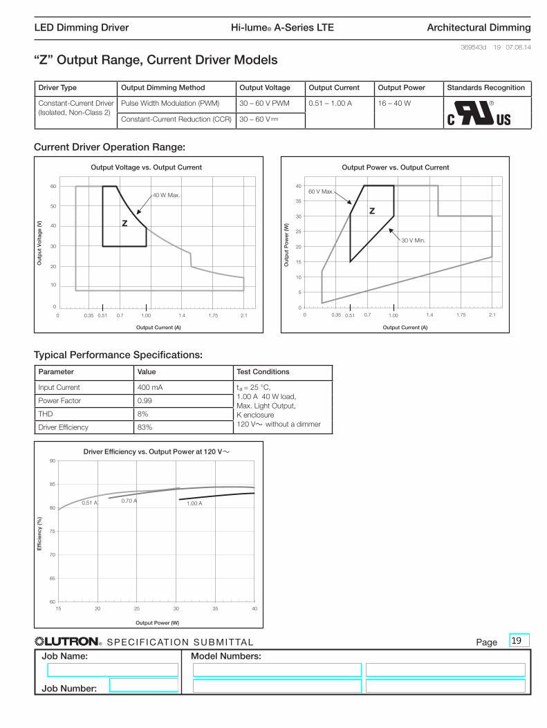
“Z” Output Range, Current Driver Models
Output Voltage vs. Output Current
Out
put
Vo
ltag
e (V
)
Output Power vs. Output Current
Out
put
Po
wer
(W)
Output Current (A)
0
10
20
30
40
50
60
0 0.35 0.7 1.4 1.75 2.1
Output Current (A)
0
5
10
15
20
25
30
35
40
0 0.35 0.7 1.4 1.75 2.10.51 1.00 0.51 1.00
Output Power (W)
Effi
cien
cy (%
)
60
65
70
75
80
85
90
15 20 25 30 35 40
Driver Efficiency vs. Output Power at 120 V~
40 W Max.
Z
30 V Min.
60 V Max.
Z
0.51 A 0.70 A 1.00 A
Current Driver Operation Range:
Typical Performance Specifications:
Output Voltage vs. Output Current
Out
put
Vo
ltag
e (V
)
Output Power vs. Output Current
Out
put
Po
wer
(W)
Output Current (A)
0
10
20
30
40
50
60
0 0.35 0.7 1.4 1.75 2.1
Output Current (A)
0
5
10
15
20
25
30
35
40
0 0.35 0.7 1.4 1.75 2.10.51 1.00 0.51 1.00
Output Power (W)
Effi
cien
cy (%
)
60
65
70
75
80
85
90
15 20 25 30 35 40
Driver Efficiency vs. Output Power at 120 V~
40 W Max.
Z
30 V Min.
60 V Max.
Z
0.51 A 0.70 A 1.00 A
Parameter Value Test Conditions
Input Current 400 mA ta = 25 °C, 1.00 A 40 W load, Max. Light Output, K enclosure 120 V~ without a dimmer
Power Factor 0.99
THD 8%
Driver Efficiency 83%
Driver Type Output Dimming Method Output Voltage Output Current Output Power Standards Recognition
Constant-Current Driver (Isolated, Non-Class 2)
Pulse Width Modulation (PWM) 30 – 60 V PWM 0.51 – 1.00 A 16 – 40 W
Constant-Current Reduction (CCR) 30 – 60 V-

® SPECIF ICAT ION SUBMITTAL Page
Job Name:
Job Number:
Model Numbers:
LED Dimming Driver Hi-lume® A-Series LTE Architectural Dimming
369543d 20 07.08.14
K Case: Case Dimensions
K Case: Connector Location Dimensions
B
FG
J* C
H*
A
E D
I*
M N
O P
R*
K*
Q
L
K*
Q
L
A 4.20 in (107 mm)B 1.00 in (25 mm)C 3.00 in (76 mm)D 4.90 in (124 mm)E 4.60 in (117 mm) (mounting center)
F 1.42 in (36 mm)G 1.99 in (51 mm)H* 1.11 in (28 mm)I* 2.00 in (51 mm)J* 1.60 in (41 mm)
K* 0.33 in (8.3 mm)L 0.65 in (16.5 mm)M 0.75 in (19 mm)N 1.73 in (44 mm)O 1.33 in (34 mm)
* Applies to studded K case only.
8-32 Threaded
Studs*
P 0.74 in (19 mm)Q 0.32 in (8 mm)R* 0.29 in (7 mm)

® SPECIF ICAT ION SUBMITTAL Page
Job Name:
Job Number:
Model Numbers:
LED Dimming Driver Hi-lume® A-Series LTE Architectural Dimming
369543d 21 07.08.14
D
C
B A
M Case: Case Dimensions
A 14.125 in (359 mm)B 13.68 in (347 mm) (mounting center)C 1.18 in (30 mm)D 1.00 in (25 mm)
K Case: Side Entry Connector Location Dimensions (Non-Studded)
S
UV
TS 1.38 in (35 mm)T 0.64 in (16 mm)U 0.88 in (22 mm)V 1.53 in (39 mm)

® SPECIF ICAT ION SUBMITTAL Page
Job Name:
Job Number:
Model Numbers:
LED Dimming Driver Hi-lume® A-Series LTE Architectural Dimming
369543d 22 07.08.14
Wiring
Controls Requiring Neutral
Note: Colors shown correspond to terminals on driver.
Wiring Diagram
1 Ground wire connection available on K case models only. Fixture and driver case must be grounded in accordance with local and national electrical codes.
2 For maximum driver-to-LED light engine wire length, see charts in Driver Wiring and Mounting section.
Compatible Controls: Lutron® Neutral-wire Dimmers
Guaranteed performance specifications with the controls listed in the chart below.
For assistance selecting controls, contact our LED Center of Excellence at 1.877.346.5338 or [email protected]
Product Part Number Low-End Setting/Load-Type Setting*Drivers per Control
A: Not Ganged B: End of Gang C: Middle of Gang
Maestro Wireless® dimmer
MRF2-6ND-120-
Trim low-end per Advanced Programming Mode App Note (Lutron® P/N 048370)
1 – 8 1 – 8 1 – 8
HomeWorks® QS adaptive dimmer HQRD-6NA- LED Lutron® A-Series 2-Wire 1 – 8 1 – 8 1 – 8
HomeWorks® QS 600 W dimmer HQRD-6ND- LED Lutron® A-Series 2-Wire 1 – 8 1 – 8 1 – 8
HomeWorks® QS 1000 W dimmer HQRD-10ND- LED Lutron® A-Series 2-Wire 1 – 13 1 – 13 1 – 13
Stanza® dimmer SZ-6ND- Trim low-end per Dimmer Installation Guide 1 – 8 1 – 8 1 – 8
RadioRA® 2 adaptive dimmer RRD-6NA- Hi-lume® A-Series LTE LED Driver
2-Wire 1 – 8 1 – 8 1 – 8
RadioRA® 2 1000 W dimmer RRD-10ND-
Set Device type to “INC/MLV Neutral Dimmer”; Set High-End Trim to 99%; Set Low-End Trim to 35%
1 – 13 1 – 13 1 – 13
A B B B C B
LutronR Neutral-wire
Forward Phase
Dimmer
Hi-lume® A-Series LED
Dimming Driver
LED Light Engine
Dimmed Line (Black)Line +V (Red)2
–V (Black)2Neutral (White)
Neutral
Neutral
Ground1
Ground1
Ground (Green)1
* Setting the low-end trim and load type is necessary to ensure optimal performance and 1% dimming capability.
Note: For information about Legacy Product use in existing control application, contact [email protected]

® SPECIF ICAT ION SUBMITTAL Page
Job Name:
Job Number:
Model Numbers:
LED Dimming Driver Hi-lume® A-Series LTE Architectural Dimming
369543d 23 07.08.14
Wiring (continued)
Controls Requiring Neutral (continued)
Note: Colors shown correspond to terminals on driver.
Wiring Diagram
1 Enclosure must be grounded in accordance with local and national electrical codes. Ground provided by grounding of junction box or by using the green ground wire connection.
2 For maximum driver-to-LED light engine wire length, see charts in Driver Wiring and Mounting section.
Compatible Controls: Lutron® Dimming Modules/PanelsGuaranteed performance specifications with the controls listed in the chart below.
For assistance selecting controls, contact our LED Center of Excellence at 1.877.346.5338 or [email protected]
Product Part Number Drivers per Control Low-End Setting/Load-Type Setting*
HomeWorks® QS wallbox power module HQRJ-WPM-6D-120- 1 – 10 (per output); 26 total per module LED Lutron® A-Series 2-Wire
HomeWorks® wallbox power module HWI-WPM-6D-120 1 – 10 (per output); 26 total per module Set load type to “GRX-FDBI or GRX-TVI”
GRAFIK Eye® QS control unit QSGR-, QSGRJ-
1 – 10 (per output); 26 total per unit Set load type to “Fluorescent Module”
GRAFIK Eye® 3000 control unit GRX-3100-, GRX-3500-
1 – 10 (per output); 26 total per module Set load type to “GRX-FDBI or GRX-TVI”
RPM-4U module (LCP, HomeWorks® QS, GRAFIK SystemsTM, Quantum®)
HW-RPM-4U-120, LP-RPM-4U-120
1 – 26 (per output); 26 total per module
LED Lutron® A-Series 2-Wire
Set load type to “2-1”
RPM-4A module (LCP, HomeWorks® QS, GRAFIK SystemsTM, Quantum®)
HW-RPM-4A-120, LP-RPM-4A-120
1 – 13 (per output); 26 total per module
LED Lutron® A-Series 2-Wire
Set load type to “2-1”
GP dimming panels Various 1 – 26 Set load type to “2-1”
* Setting the low-end trim and load type is necessary to ensure optimal performance and 1% dimming capability.
LutronR Dimming
Module/Panel
Hi-lume® A-Series LED
Dimming Driver
LED Light Engine
Dimmed Line (Black)Line +V (Red)2
–V (Black)2Neutral
Neutral (White)
Neutral
Ground1
Ground1
Ground (Green)1

® SPECIF ICAT ION SUBMITTAL Page
Job Name:
Job Number:
Model Numbers:
LED Dimming Driver Hi-lume® A-Series LTE Architectural Dimming
369543d 24 07.08.14
Wiring (continued)
Controls Not Requiring Neutral
Note: Colors shown correspond to terminals on driver.
Wiring Diagram
1 Ground wire connection available on K case models only. Fixture and driver case must be grounded in accordance with local and national electrical codes.
2 For maximum driver-to-LED light engine wire length, see charts in Driver Wiring and Mounting section.
LutronR Non-Neutral
Forward Phase
Dimmer
Hi-lume® A-Series LED
Dimming Driver
LED Light Engine
Dimmed Line (Black)Line +V (Red)2
–V (Black)2Neutral (White)Neutral
Ground1
Ground1
Ground (Green)1
Compatible Controls: Lutron® Non-Neutral Dimmers
Guaranteed performance specifications with the controls listed in the chart below.
For assistance selecting controls, contact our LED Center of Excellence at 1.877.346.5338 or [email protected]
Product Part Number Low-End Setting/Load-Type Setting*Drivers per Control
A: Not Ganged B: End of Gang C: Middle of Gang
Ariadni® C•L® 250 W dimmer AYCL-253P-
Set low-end trim dial to 1 o’clock. Adjust slightly if needed. See Figure 1 under ‘Dimmer Range Adjustment’ section in the Dimmer Installation Guide for how to adjust low-end trim.
1 – 8 1 – 8 1 – 8
Diva® C•L® 250 W dimmer
DVCL-253P- Set low-end trim dial to 10 o’clock. Adjust slightly if needed. See Figure 1 under ‘Dimmer Range Adjustment’ section in the Dimmer Installation Guide for how to adjust low-end trim.
1 – 8 1 – 8 1 – 8
DVSCCL-253P- 1 – 8 1 – 8 1 – 8
A B B B C B
* Setting the low-end trim and load type is necessary to ensure optimal performance and 1% dimming capability.
Note: For information about Legacy Product use in existing control application, contact [email protected]

® SPECIF ICAT ION SUBMITTAL Page
Job Name:
Job Number:
Model Numbers:
LED Dimming Driver Hi-lume® A-Series LTE Architectural Dimming
369543d 25 07.08.14
ELECTRICIANS AND CONTRACTORS
Driver Leads
Maximum driver-to-LED light engine wire length for Constant-Current Drivers:
Maximum driver-to-LED light engine wire length for Constant-Voltage Drivers:
Wiring and Grounding
Driver and lighting fixture must be grounded. Drivers must be installed per national and local electrical codes.
LED Load Replacement
For Class 2 rated drivers, the LED load can be changed while the driver is installed and powered.
Maximum Driver Operating Temperature
Driver case temperature (tc) must not exceed UL conditions of acceptability in end product.
For 50,000 hour lifetime, driver case temperature (tc)must not exceed 65 °C.
FACILITIES MANAGERS
SERVICE
Warranty
For warranty information, please visit http://www.lutron.com/BallastDriverWarranty.pdf
Replacement Parts
When ordering Lutron® replacement parts please provide the full model number. Consult Lutron if you have any questions.
Further Information
For further information, please visit us at www.lutron.com/hilumeLED or contact our LED Control Center of Excellence at 1.877.346.5338 or [email protected]
Wire GaugeMaximum Lead Length
200 mA to 700 mA
710 mA to 1.50 A
1.51 A to 2.10 A
18 AWG (0.75 mm2) 30 ft (9 m) 15 ft (4.5 m) 10 ft (3 m)
16 AWG (1.5 mm2) 35 ft (10.5 m) 25 ft (7.5 m) 15 ft (4.5 m)
14 AWG (2.5 mm2) 50 ft (15 m) 40 ft (12 m) 25 ft (7.5 m)
12 AWG (4.0 mm2) 100 ft (30 m) 60 ft (18 m) 40 ft (12 m)
Wire GaugeMaximum Lead Length
10 to 20 V- 20.5 to 40 V- 40.5 to 60 V-
18 AWG (0.75 mm2) 10 ft (3 m) 15 ft (4.5 m) 30 ft (9 m)
16 AWG (1.5 mm2) 15 ft (4.5 m) 25 ft (7.5 m) 50 ft (15 m)
14 AWG (2.5 mm2) 25 ft (7.5 m) 40 ft (12 m) 75 ft (22.5 m)
12 AWG (4.0 mm2) 40 ft (12 m) 60 ft (18 m) 100 ft (30 m)