Embed Size (px)
Citation preview
Software within building physics and ground heat storage
BLOCON
www.buildingphysics.com
HEAT2 version 10 A PC-program for heat transfer in two dimensions - Update manual
March 1, 2016

2

3
Contents
1. WHAT’S NEW IN HEAT2 VERSION 10...................................................................... 5
1.1 SCRIPT FOR PRE-PROCESSOR ....................................................................................... 5 1.2 REPEATING FUNCTION VALUES.................................................................................... 5 1.3 CHANGEABLE USER INTERFACE OF HEAT2 ................................................................ 5 1.4 LIGHT VERSION ............................................................................................................ 5 1.5 INSTALLATION AND REQUIREMENTS ........................................................................... 6
2. SCRIPT FOR PRE-PROCESSOR ................................................................................. 7
2.1 INTRODUCTION ............................................................................................................ 7 2.2 EXECUTING THE SCRIPT ............................................................................................... 8 2.3 IMPORTING GEOMETRY FROM PRE-PROCESSOR TO SCRIPT ........................................ 11 2.4 ADJUSTMENT OF THE SCALE-FACTOR ........................................................................ 14 2.5 HELP .......................................................................................................................... 15 2.6 ADJUSTMENT OF POLYGON GRID STEP ....................................................................... 16 2.7 SAVE/OPEN SCRIPT FILES ........................................................................................... 17
3. REPEATING FUNCTION VALUES ........................................................................... 19
3.1 INTRODUCTION .......................................................................................................... 19 3.2 EXAMPLE ................................................................................................................... 20
4. CHANGEABLE USER INTERFACE OF HEAT2 ..................................................... 23
4.1 INTRODUCTION .......................................................................................................... 23

4

5
1. What’s new in HEAT2 version 10 Blocon is proud to present a new version of HEAT2. Many new important features have been added.
Up-to-date information is given on www.buildingphysics.com.
This update manual covers new features that have been added since version 8. New users should also
read the update manuals for versions 6, 7, 8, 9 and the full manual for version 5 at
http://www.buildingphysics.com/manuals/HEAT2_9_update.pdf
http://www.buildingphysics.com/manuals/HEAT2_8_update.pdf
http://www.buildingphysics.com/manuals/HEAT2_7_update_english.pdf
http://www.buildingphysics.com/manuals/Heat2_6_update.pdf
http://www.buildingphysics.com/manuals/HEAT2_5.pdf
Tips for reading for beginners: For a quick start read Chapter 4 (pages 23-27) in Manual HEAT2
5.0. The example in chapter 8 (pages 117-121) would also give a short introduction. After this, look at
the update manuals for versions 6, 7, 8, and 9. Also see the examples for the test cases: ISO 10211 &
10077-2 validation test cases
1.1 Script for pre-processor
The complete geometry can now be described by text. It is also possible to vice versa convert already
drawn geometry in the pre-processor to a script. See Chapter 2.
1.2 Repeating function values
It is now easy to repeat functions values for dynamic calculations for any period. See Chapter 3.
1.3 Changeable user interface of HEAT2
The user interface of HEAT2 can now be “personalized” using different windows style themes. See
Chapter 4.
1.4 Light version
The light (demo) version has the following restrictions:
Data cannot be saved.
Materials cannot be added or changed.
Max 1,000,000 (1,000·1,000) nodes.
Results for heat flows are hidden for larger problems with more than 5,000 nodes and with
more than 60 nodes in each direction.
Thermal coupling coefficients (L2D) will not be calculated.
Report preview is disabled.
Some other restrictions apply.

6
1.5 Installation and requirements
HEAT2 v10 requires only about 0.2 GB RAM (a pc with 2 GB is recommended), and less than 10
MB hard disk space. HEAT2 runs on both 32-bit and 64-bit Windows 10, 8, and 7.
Install HEAT2 by clicking on the setup file. If there is any problem (such as HEAT2 cannot find the
material files) please check the below.
Note that HEAT2/HEAT3 cannot be started directly by clicking on the exe-files. The programs
should be started using the short-cuts on the start menu (or your own short-cuts on the desktop, see
below how to create this).
By default, the setup program installs HEAT2_v10_xx.exe and some other files to folder
C:\Program Files (x86)\BLOCON\HEAT2_v10.xx\
The material files (*.mtl) and some other user files are placed in
C:\Documents and Settings\*username*\My Documents\BLOCON\HEAT2 10
This folder contains also user projects files. It needs local write/read rights.
Make sure that the short-cut for "HEAT2 v10.xx" in the start-menu (right-click properties on the
short-cut) has "Target" set to ”C:\Program Files
(x86)\BLOCON\HEAT2_v10.xx\HEAT2_v10.xx.exe“ (or wherever the exe-file is located) and
"Start in" set to "...Documents\Blocon\HEAT2 10" (or wherever the files are located). The short-
cut for "HEAT2 v10.xx can be found in folder “C:\ProgramData\Microsoft\Windows\Start
Menu\Programs\BLOCON”.
The installation with the setup file will automatically create correct folders. Administrators rights are
needed for the setup since the setup-program writes in the registry and program folders.
If needed, you can also make shortcuts on the desktop for each user with properties set to
Target: "C:\Program Files\Blocon\HEAT2_v10.xx\HEAT2_v10.xx.exe"
and
Start in: "…User1\My Documents\Blocon\HEAT2 10" for user1
Start in: "…User2\My Documents\Blocon\HEAT2 10" for user2
etc.
Each folder should contain copies of the original material files (.mtl and Mtrl50.txt), ini-file, and
projects files. (The same that was installed). The folders needs local write/read wrights. This way,
each user has his/her own files.

7
2. Script for Pre-processor
2.1 Introduction
Geometrical input can now be given using text scripts. It is possible to run different scripts in order to
build a complete geometry. E.g. the user can have different scripts describing e.g. wall types and
combine those with different scripts describing e.g. window frames.
It is also possible to vice versa generate a script from an already drawn geometry in the pre-processor.
This means that a user can “export” already drawn geometries from the pre-processor and save them
in a library for future use.
Do not confuse scripts for the pre-processor with scripts for bitmaps, see further p. 44-48 in
http://www.buildingphysics.com/manuals/HEAT2_9_update.pdf
The following script commands are possible.
Rectangles can be specified using one of the below options:
r x1 y1 x2 y2 material name => rectangle using two points (x,y)
s x1 y1 w h material name => rectangle using point (x1,y1), width, height
t x1 y1 w h angle material name => tilted rectangle using point (x1,y1), width, height, angle [°]
Polygons are specified using
m x1 y1 x2 y2 x3 y3 ... xn yn material name => polygon using n points (x,y) (at least three points)
The “material name” above should be a string from the material list, e.g. “concrete, IEA”. If no
material is given, the last one specified will be used (if no material has been used before, the current
material in the material list will be used). This script will draw two rectangles with “concrete, IEA”:
R 0.1 0.1 0.5 0.2 concrete, IEA
R 0.3 0.4 0.7 0.2
If a material does not exist, the last one specified will be used. This script will draw two rectangles
with “concrete, IEA”:
R 0.1 0.1 0.5 0.2 concrete, IEA
R 0.3 0.4 0.7 0.2 dummymaterial
Note the message in the “Message Window”: “Material not found in material list: dummymaterial”
There is a short cut to insert the current material from the material list: Ctrl-N (or menu item
“Edit/Insert material name”.
Expansion points are specified using
x x1 y1 => expansion point at (x1,y1)
Open boundary line segments are specified using
b x1 y1 => open boundary line segment at (x1,y1)
Origo can be moved by
o x1 y1 => set new origo reference at (x1,y1)
Comments are given by
! comments starts with an exclamation mark
A tip: comment out objects if you do not want to draw them:
! R 0.1 0.1 0.5 0.2 concrete, IEA

8
2.2 Executing the script
The script window is available from the top menu bar in the pre-processor:
The button ”Run (script => pre-processor)” (or short cut Ctrl+R) will execute the script. The
example above will generate the following geometry with eight objects drawn:

9
The geometry will be added to the existing pre-processor drawing If “Empty pre-processor before
running script” is not checked.
In the example below we have inserted “o 0.2 0.2” which means that we move the origo with offset
(0.2, 0.2) and then all objects are added again referenced to the new origo.
This will give the following geometry:
Note that all objects for the last imported script will be marked (in red) thus making it easier to move,
delete, etc.

10
Running the script again will give:
Setting a new origo can be useful e.g. in the following scenario: Assume you have a script that
describes a detail (e.g. a window frame). You can use the same script over and over again and place
the detail anywhere by first setting a new origo as a reference.

11
2.3 Importing geometry from pre-processor to script
The button “Import [ pre-processor => script ]” will generate a script for the drawn objects.
Assume we have the first example (see file example1.txt in folder “Scripts_preprocessor”) where the
geometry was generated by the following script:

12
First, uncheck “Set origo to lower left in pre-processor” and press the button “Import [ pre-
processor => script ]”. The generated script will be as follows:
A comment is shown on the first row (and at the window bottom) when the script was generated.
Note that the exported rectangle “s 0.55 0 0.1 0.3 concrete, IEA” is imported as “r 0.55 0 0.65 0.3
concrete, IEA”, and that the tilted rectangle “t 0.15 0.1 0.15 0.3 30 glass, lead” is imported as a
polygon “m 0.15 0.1 0.28 0.175 0.13 0.435 0 0.36 glass, lead”.
If “Set origo to lower left in pre-processor” is checked, the origo will always be at the lower left. The
generated script will now be as follows:
The lower left-most object is here “r 0 0 0.4 0.4 concrete, IEA”.
13
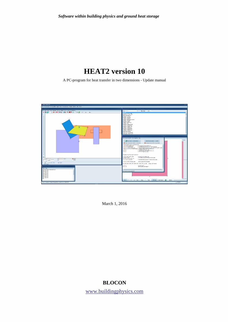
The script for case “ISO10077_D6.dat” is shown below.
14
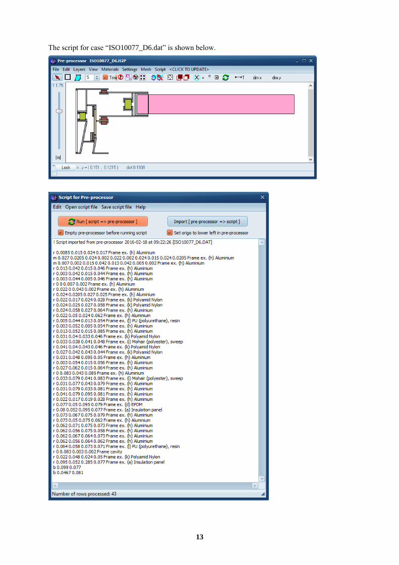
2.4 Adjustment of the scale-factor
The scale factor should initially be set according to the smallest width that is to be drawn, see p. 45 at
http://www.buildingphysics.com/manuals/HEAT2_5.pdf
By default, the scale factor is 10 which would give 10 mm:
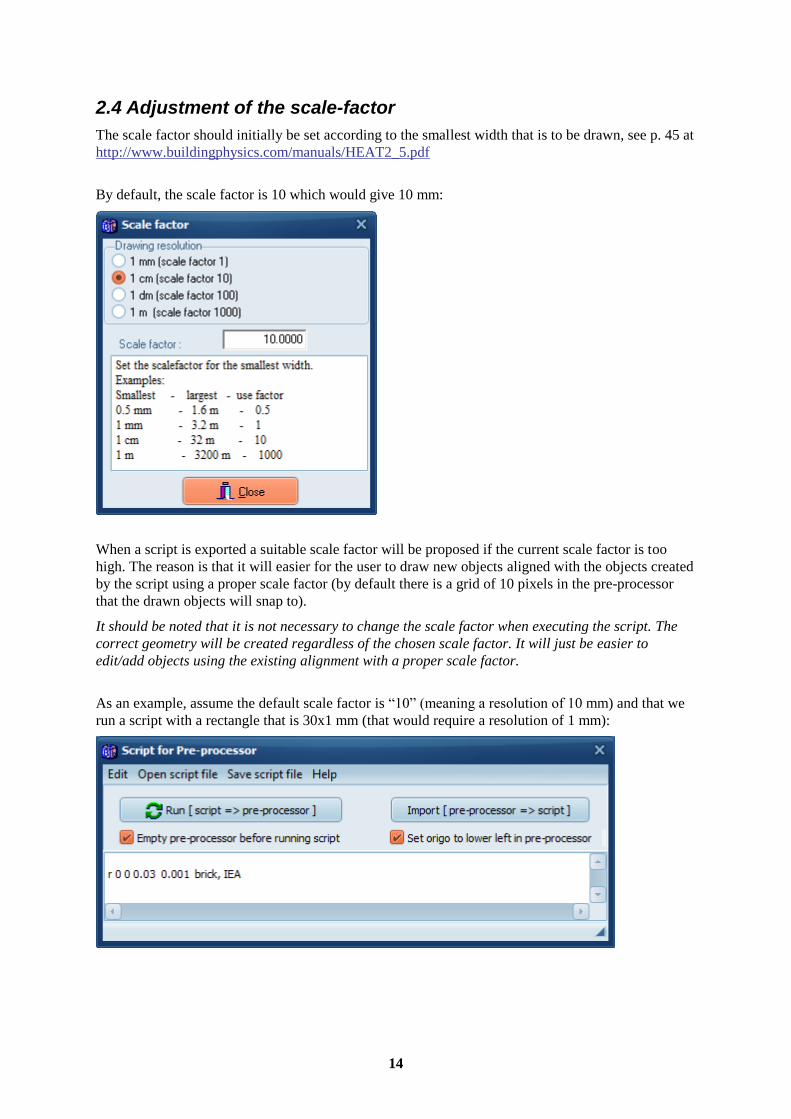
When a script is exported a suitable scale factor will be proposed if the current scale factor is too
high. The reason is that it will easier for the user to draw new objects aligned with the objects created
by the script using a proper scale factor (by default there is a grid of 10 pixels in the pre-processor
that the drawn objects will snap to).
It should be noted that it is not necessary to change the scale factor when executing the script. The
correct geometry will be created regardless of the chosen scale factor. It will just be easier to
edit/add objects using the existing alignment with a proper scale factor.
As an example, assume the default scale factor is “10” (meaning a resolution of 10 mm) and that we
run a script with a rectangle that is 30x1 mm (that would require a resolution of 1 mm):

15
There will be a suggestion to change the scale factor when running the script:
If “Empty pre-processor before running script” is not checked, and if the pre-processor is not
empty, there will be a warning instead (if the current scale factor is too high):
So, if the pre-processor is not empty, and we want to add objects from a script, the scale factor will
not be changed if it is too high since this would affect the geometry already drawn. Only a warning
will be shown.
2.5 Help
Press menu item Help and some information will be added to the editor:
16
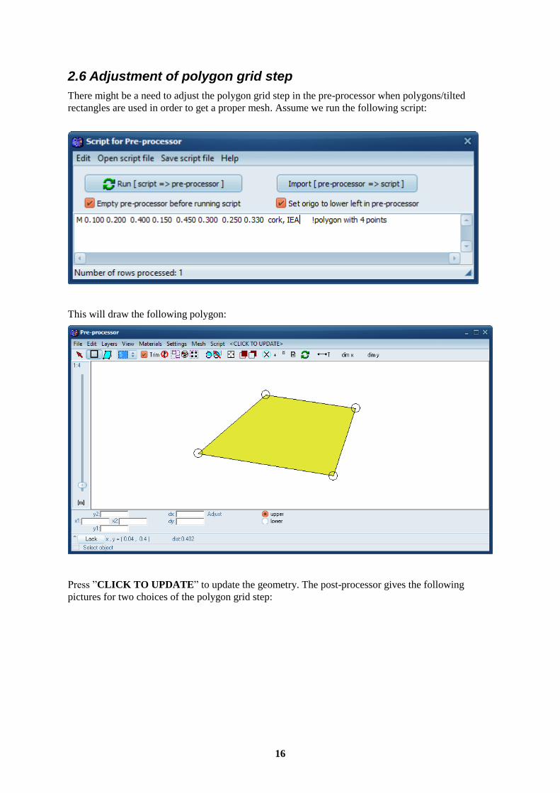
2.6 Adjustment of polygon grid step
There might be a need to adjust the polygon grid step in the pre-processor when polygons/tilted
rectangles are used in order to get a proper mesh. Assume we run the following script:
This will draw the following polygon:
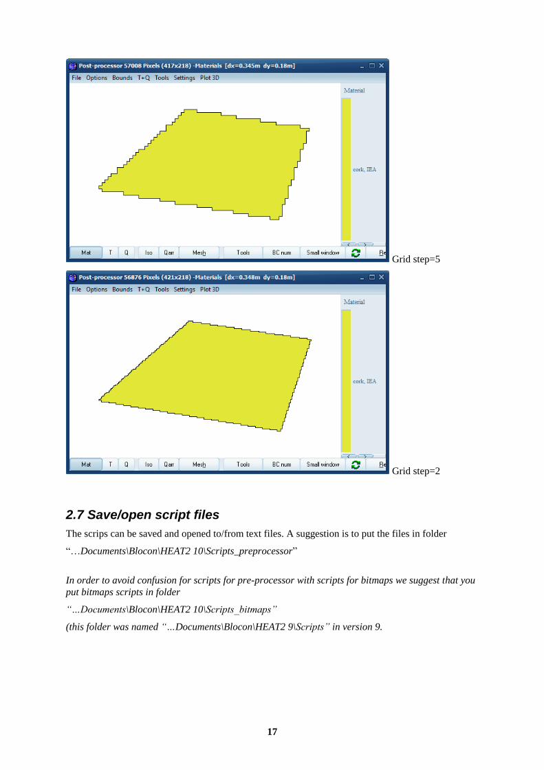
Press ”CLICK TO UPDATE” to update the geometry. The post-processor gives the following
pictures for two choices of the polygon grid step:
17
Grid step=5
Grid step=2
2.7 Save/open script files
The scrips can be saved and opened to/from text files. A suggestion is to put the files in folder
“…Documents\Blocon\HEAT2 10\Scripts_preprocessor”
In order to avoid confusion for scripts for pre-processor with scripts for bitmaps we suggest that you
put bitmaps scripts in folder
“…Documents\Blocon\HEAT2 10\Scripts_bitmaps”
(this folder was named “…Documents\Blocon\HEAT2 9\Scripts” in version 9.

18

19
3. Repeating function values
3.1 Introduction
It is now possible to easily repeat function values for dynamic calculations for any given period (e.g.
daily, weekly, monthly, or yearly variation).
To repeat the values just add the string "% repeat timestring” as the first row in a function (*.fun).
The ”timestring” is just the time given as a string, e.g. "1y2q3d4h5s", "8760h", 3600s (or just 3600),
etc. Here is a recap from http://www.buildingphysics.com/manuals/HEAT2_5.pdf how time-strings
are used:
The time-string is a sequence of pairs with a number and one of the following letters:
y year (365 days, 31536000 seconds)
q month (year/12, 30.417 days, 2628000 seconds)
d day (86400 seconds)
h hour (3600 seconds)
m minute (60 seconds)
s second (can be omitted)
Please note that m is minute and q is month. Here are some examples:
1y14h 1 year and 14 hours
14q3d15 1 year, 2 months, 3 days and 15 seconds (same as 1y2q3d15)
86400 1 day
1h2d Not valid. The expression must be in descending order, see next row.
2d1h This string is OK, meaning 2 days and 1 hour
Normally, one would use a repeat period of one day (1d), one week (7d), one month (1q), or one year
(1y). Here is an example where the values are repeated for the first three months (3q) in a function:
% repeat 3q
0m 20
1q 25
2q 15
3q 22
4q 4
5q 9
6q 13
7q 25
8q 24
Here is an example where the values are repeated for a monthly period with daily values:
% repeat 1q
0d 24
1d 23
2d 21
3d 19
4d 23
...
31d 22

20
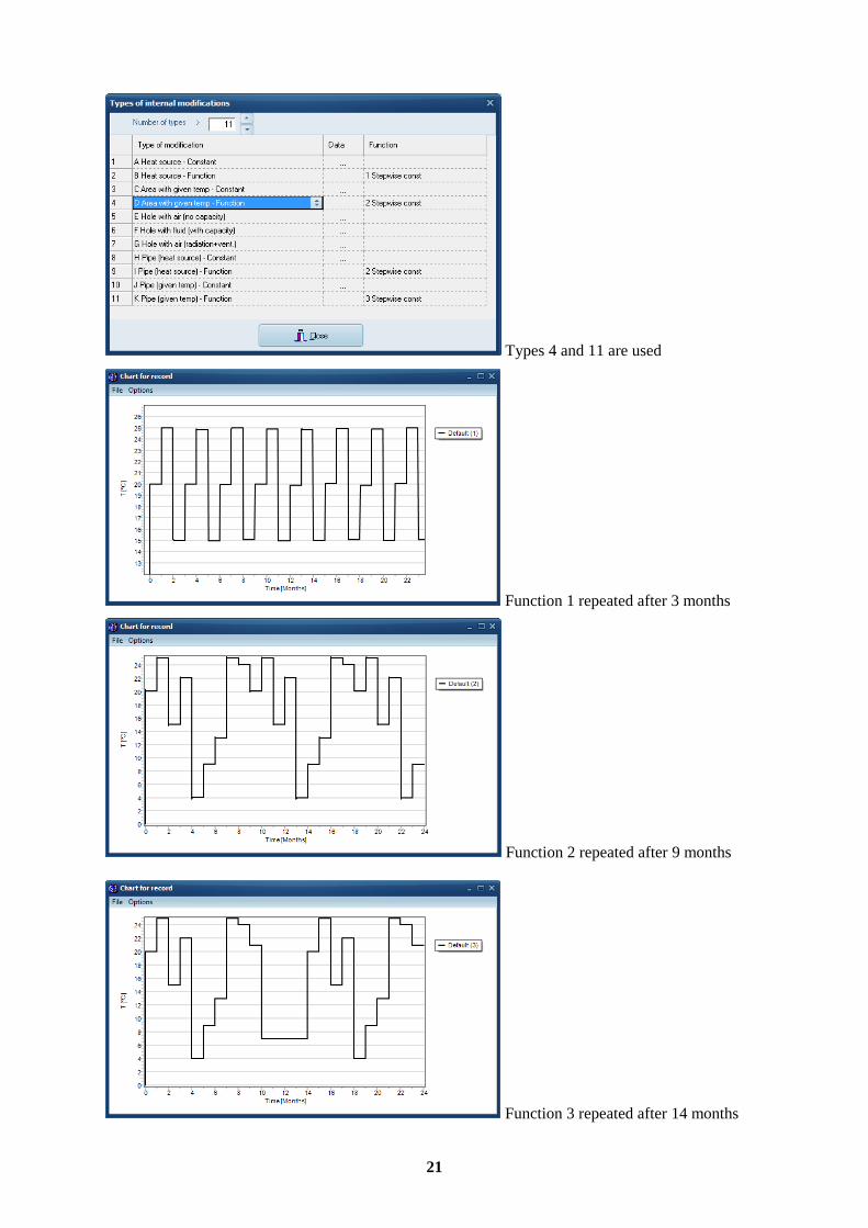
3.2 Example
The following example (Repeat_example.dat) uses three functions that are repeated for different
periods of 3, 9, and 14 months for a total of two years. All files are available in folder
“…Documents\Blocon\HEAT2 10\Examples\Manual\repeatingfunction”
Function 1 is used for the right boundary condition (stepwise constant temperature).
Function 2 is used for area 1 (type 4) with a given temperature.
Function 3 is used for area 2 (type 11) which is a pipe with a given temperature.
21
Types 4 and 11 are used
Function 1 repeated after 3 months
Function 2 repeated after 9 months
Function 3 repeated after 14 months
22
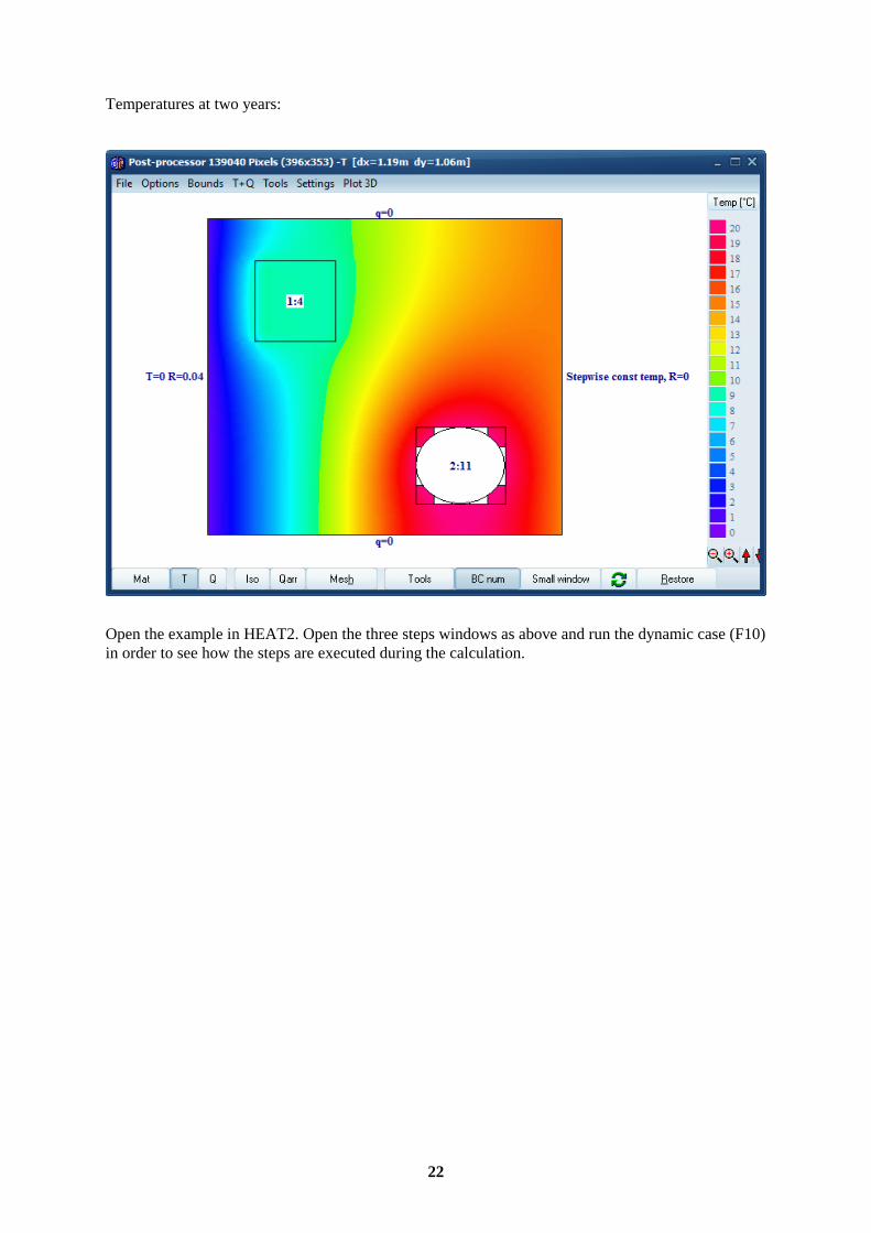
Temperatures at two years:
Open the example in HEAT2. Open the three steps windows as above and run the dynamic case (F10)
in order to see how the steps are executed during the calculation.

23
4. Changeable user interface of HEAT2
4.1 Introduction
The user interface of HEAT2 can now be “personalized” using different windows style themes. A
style is a collection of painting rules you can dynamically apply to an entire Windows application,
changing the size and appearance of various elements, the fonts, and the color scheme. One example
of the available styles is the so-called Modern UI (originally known as “Metro”).
Goto menu item Options/Themes to change current appearance:
The default theme is “Sapphire Kamri”:
Below are examples of a couple of other themes.

24
Ruby Graphite
Metropolis UI blue:
The theme is saved to file “Theme.txt” in folder “C:\Users\*username*\Documents\Blocon\HEAT2
10” and read every time HEAT2 is started.