Embed Size (px)
Citation preview

Department of Mechanical Engineering Prepared By: Mehul K. Pujara Darshan Institute of Engineering & Technology, Rajkot Page 3.1
3 HEAT TRANSFER FROM EXTENDED SURFACES
Course Contents
3.1 Introduction
3.2 Steady flow of heat along a
rod (governing differential
equation)
3.3 Heat dissipation from an
infinitely long fin
3.4 Heat dissipation from a fin
insulated at the tip
3.5 Heat dissipation from a fin
losing heat at the tip
3.6 Fin performance
3.7 Thermometric well
3.8 Solved Numerical
3.9 References
3. Heat Transfer from Extended Surface Heat Transfer (3151909)
Prepared By: Mehul K. Pujara Department of Mechanical Engineering Page 3.2 Darshan Institute of Engineering & Technology, Rajkot
3.1 Introduction
Heat transfer between a solid surface and a moving fluid is governed by the
Newton’s cooling law: 𝑄𝑐𝑜𝑛𝑣 = ℎ𝐴𝑠(𝑇0 − 𝑇𝑎), where 𝑇0 is the surface temperature
and 𝑇𝑎 is the fluid temperature.
Therefore, to increase the convective heat transfer, one can
i Increase the temperature difference (𝑇0 − 𝑇𝑎) between the surface and the fluid.
ii Increase the convection coefficient ℎ. This can be accomplished by increasing the
fluid flow over the surface since h is a function of the flow velocity and the higher
the velocity, the higher the h.
iii Increase the contact surface area 𝐴𝑠
Many times, when the first option is not in our control and the second option (i.e.
increasing h) is already stretched to its limit, we are left with the only alternative of
increasing the effective surface area by using fins or extended surfaces.
Fins are protrusions from the base surface into the cooling fluid, so that the extra
surface of the protrusions is also in contact with the fluid.
Most of you have encountered cooling fins on air-cooled engines (motorcycles,
portable generators, etc.), electronic equipment (CPUs), automobile radiators, air
conditioning equipment (condensers) and elsewhere
3.2 Steady Flow of Heat Along A Rod (Governing Differential
Equation)
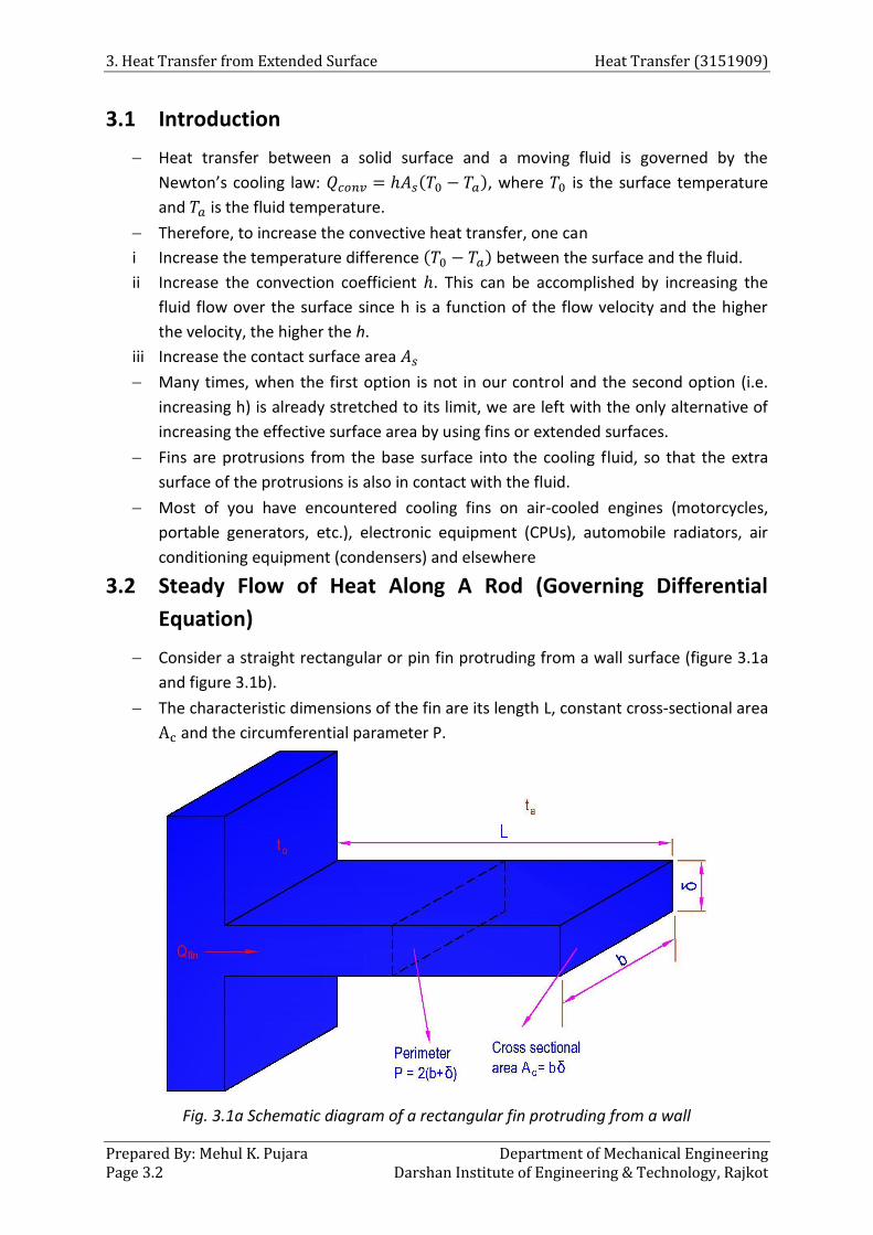
Consider a straight rectangular or pin fin protruding from a wall surface (figure 3.1a
and figure 3.1b).
The characteristic dimensions of the fin are its length L, constant cross-sectional area
Ac and the circumferential parameter P.
Fig. 3.1a Schematic diagram of a rectangular fin protruding from a wall

Heat Transfer (3151909) 3. Heat Transfer from Extended Surface
Department of Mechanical Engineering Prepared By: Mehul K. Pujara Darshan Institute of Engineering & Technology, Rajkot Page 3.3
Fig. 3.1b Schematic diagram of a pin fin protruding from a wall
Thus for a rectangular fin
𝐴𝑐 = 𝑏𝛿 ; 𝑃 = 2(𝑏 + 𝛿)
And for a pin fin
Ac =π
4d2 ; P = πd
The temperature at the base of the fin is T0 and the temperature of the ambient
fluid into which the rod extends is considered to be constant at temperatureTa.
The base temperature T0 is highest and the temperature along the fin length goes on
diminishing.
Analysis of heat flow from the finned surface is made with the following
assumptions:
i Thickness of the fin is small compared with the length and width; temperature
gradients over the cross-section are neglected and heat conduction treated one
dimensional
ii Homogeneous and isotropic fin material; the thermal conductivity k of the fin
material is constant
iii Uniform heat transfer coefficient h over the entire fin surface
iv No heat generation within the fin itself
v Joint between the fin and the heated wall offers no bond resistance;
temperature at root or base of the fin is uniform and equal to temperature 𝑇0 of
the wall
vi Negligible radiation exchange with the surroundings; radiation effects, if any, are
considered as included in the convection coefficient h

3. Heat Transfer from Extended Surface Heat Transfer (3151909)
Prepared By: Mehul K. Pujara Department of Mechanical Engineering Page 3.4 Darshan Institute of Engineering & Technology, Rajkot
vii Steady state heat dissipation
Heat from the heated wall is conducted through the fin and convected from the
sides of the fin to the surroundings.
Consider infinitesimal element of the fin of thickness dx at a distance x from base
wall as shown in figure 3.2.
Fig. 3.2 Heat transfer through a fin
Heat conducted into the element at plane x
𝑄𝑥 = −𝑘 𝐴𝑐 (𝑑𝑡
𝑑𝑥)
𝑥− − − − − − − −(3.1)
Heat conducted out of the element at plane (𝑥 + 𝑑𝑥)
𝑄𝑥+𝑑𝑥 = −𝑘 𝐴𝑐 (𝑑𝑡
𝑑𝑥)
𝑥+𝑑𝑥
= −𝑘 𝐴𝑐
𝑑
𝑑𝑥(𝑡 +
𝑑𝑡
𝑑𝑥𝑑𝑥) − − − − − − − −(3.2)
Heat convected out of the element between the planes x and (𝑥 + 𝑑𝑥)
𝑄𝑐𝑜𝑛𝑣 = ℎ (𝑃 𝑑𝑥)(𝑡 − 𝑡𝑎) − − − − − − − −(3.3)
Here temperature t of the fin has been assumed to be uniform and non-variant for
the infinitesimal element.
According to first law of thermodynamic, for the steady state condition, heat
transfer into element is equal to heat transfer from the element
𝑄𝑥 = 𝑄𝑥+𝑑𝑥 + 𝑄𝑐𝑜𝑛𝑣

Heat Transfer (3151909) 3. Heat Transfer from Extended Surface
Department of Mechanical Engineering Prepared By: Mehul K. Pujara Darshan Institute of Engineering & Technology, Rajkot Page 3.5
−𝑘 𝐴𝑐
𝑑𝑡
𝑑𝑥= −𝑘 𝐴𝑐
𝑑
𝑑𝑥(𝑡 +
𝑑𝑡
𝑑𝑥𝑑𝑥) + ℎ (𝑃 𝑑𝑥)(𝑡 − 𝑡𝑎)
−𝑘 𝐴𝑐
𝑑𝑡
𝑑𝑥= −𝑘 𝐴𝑐
𝑑𝑡
𝑑𝑥− 𝑘 𝐴𝑐
𝑑2𝑡
𝑑𝑥2 𝑑𝑥 + ℎ (𝑃 𝑑𝑥)(𝑡 − 𝑡𝑎)
Upon arrangement and simplification
𝑑2𝑡
𝑑𝑥2−
ℎ𝑃
𝑘 𝐴𝑐
(𝑡 − 𝑡𝑎) = 0 − − − − − − − −(3.4)
Let, 𝜃(𝑥) = 𝑡(𝑥) − 𝑡𝑎
As the ambient temperature is constant, so differentiation of the equation is
𝑑𝜃
𝑑𝑥=
𝑑𝑡
𝑑𝑥;
𝑑2𝜃
𝑑𝑥2=
𝑑2𝑡
𝑑𝑥2
Thus
𝑑2𝜃
𝑑𝑥2− 𝑚2𝜃 = 0 − − − − − − − −(3.5)
Where
𝑚 = √ℎ𝑃
𝑘 𝐴𝑐
Equations 3.4 and 3.5 provide a general form of the energy equation for one
dimensional heat dissipation from an extended surface.
The general solution of this linear homogeneous second order differential equation
is of the form
θ = C1emx + C2e−mx − − − − − − − −(3.6)
The constant C1 and C2 are to be determined with the aid of relevant boundary
conditions. We will treat the following four cases:
i Heat dissipation from an infinitely long fin
ii Heat dissipation from a fin insulated at the tip
iii Heat dissipation from a fin losing heat at the tip
3.3 Heat Dissipation From an Infinitely Long Fin
Governing differential equation for the temperature distribution along the length of
the fin is given as,
𝜃 = 𝐶1𝑒𝑚𝑥 + 𝐶2𝑒−𝑚𝑥 − − − − − − − −(3.7)
The relevant boundary conditions are

3. Heat Transfer from Extended Surface Heat Transfer (3151909)
Prepared By: Mehul K. Pujara Department of Mechanical Engineering Page 3.6 Darshan Institute of Engineering & Technology, Rajkot
Fig. 3.3 Temperature distribution along the infinite long fin
Temperature at the base of fin equals the temperature of the surface to which the
fin is attached.
𝑡 = 𝑡0 𝑎𝑡 𝑥 = 0
In terms of excess temperature
𝑡 − 𝑡𝑎 = 𝑡0 − 𝑡𝑎 𝑎𝑡 𝑥 = 0
or 𝜃 = 𝜃0 𝑎𝑡 𝑥 = 0
Substitution of this boundary condition in equation gives:
𝐶1 + 𝐶2 = 𝜃0 − − − − − − − −(3.8)
Temperature at the end of an infinitely long fin equals that of the surroundings.
𝑡 = 𝑡𝑎 𝑎𝑡 𝑥 = ∞
𝜃 = 0 𝑎𝑡 𝑥 = ∞
Substitution of this boundary condition in equation gives:
𝐶1𝑒𝑚∞ + 𝐶2𝑒−𝑚∞ = 0 − − − − − − − −(3.9)
Since the term 𝐶2𝑒−𝑚∞ is zero, the equality is valid only if 𝐶1 = 0. Then from
equation 3.8 𝐶2 = 𝜃0.
Substituting these values of constant 𝐶1 and 𝐶2 in equation 3.7, following expression
is obtained for temperature distribution along the length of the fin.
𝜃 = 𝜃0𝑒−𝑚𝑥; (𝑡 − 𝑡𝑎) = (𝑡0 − 𝑡𝑎)𝑒−𝑚𝑥 − − − − − − − −(3.10)
Heat transfer from fin
Heat transfer to the fin at base of the fin must equal to the heat transfer from the
surface of the fin by convection. Heat transfer to the fin at base is given as
𝑄𝑓𝑖𝑛 = −𝑘 𝐴𝑐 (𝑑𝑡
𝑑𝑥)
𝑥=0− − − − − − − −(3.11)
From the expression for the temperature distribution (Equation 3.10)
𝑡 = 𝑡∞ + (𝑡0 − 𝑡𝑎)𝑒−𝑚𝑥

Heat Transfer (3151909) 3. Heat Transfer from Extended Surface
Department of Mechanical Engineering Prepared By: Mehul K. Pujara Darshan Institute of Engineering & Technology, Rajkot Page 3.7
(𝑑𝑡
𝑑𝑥)
𝑥=0= [−𝑚(𝑡0 − 𝑡𝑎)𝑒−𝑚𝑥]𝑥=0
= −𝑚(𝑡0 − 𝑡𝑎)
Substitute the value of (𝑑𝑡
𝑑𝑥)
𝑥=0 in the equation 3.11
∴ 𝑄𝑓𝑖𝑛 = 𝑘 𝐴𝑐𝑚(𝑡0 − 𝑡𝑎)
But
𝑚 = √ℎ𝑃
𝑘 𝐴𝑐
∴ 𝑄𝑓𝑖𝑛 = √𝑃ℎ𝑘𝐴𝑐 (𝑡0 − 𝑡𝑎) − − − − − − − −(3.12)
The temperature distribution (Equation 3.10) would suggest that the temperature
drops towards the tip of the fin.
Hence area near the fin tip is not utilized to the extent as the lateral area near the
base. Obviously an increase in length beyond certain point has little effect on heat
transfer.
So it is better to use tapered fin as it has more lateral area near the base where the
difference in temperature is high.
Ingen-Hausz Experiment
Fig. 3.4 Setup of Ingen-Hausz’s Experiment
Heat flow rates through solids can be compared by having an arrangement
consisting essentially of a box to which rods of different materials are attached
(Ingen-Hausz experiment).
The rods are of same length and area of cross-section (same size and shape); their
outer surfaces are electroplated with the same material and are equally polished.
This is to ensure that for each rod, the surface heat transfer will be same. Heat flow
from the box along the rod would melt the wax for a distance which would depend
upon the rod material. Let
𝜃0= excess of temperature of the hot bath above the ambient temperature
𝜃𝑚= excess of temperature of melting point of wax above the ambient temperature
𝑙1, 𝑙2, 𝑙3……… = lengths upto which wax melts.
Then for different rods (treating each as fin of infinite length),
𝜃𝑚 = 𝜃0𝑒−𝑚1𝑙1

3. Heat Transfer from Extended Surface Heat Transfer (3151909)
Prepared By: Mehul K. Pujara Department of Mechanical Engineering Page 3.8 Darshan Institute of Engineering & Technology, Rajkot
= 𝜃0𝑒−𝑚2𝑙2
= 𝜃0𝑒−𝑚3𝑙3
So
𝑚1𝑙1 = 𝑚2𝑙2 = 𝑚3𝑙3
or
√ℎ𝑃
𝐾1𝐴𝑙1 = √
ℎ𝑃
𝐾2𝐴𝑙2 = √
ℎ𝑃
𝐾3𝐴𝑙3
or
𝑙1
√𝑘1
=𝑙2
√𝑘2
=𝑙3
√𝑘3
= 𝑐𝑜𝑛𝑠𝑡𝑎𝑛𝑡 − − − − − − − −(3.13)
or
𝑘1
𝑙12 =
𝑘2
𝑙22 =
𝑘3
𝑙32 = 𝑐𝑜𝑛𝑠𝑡𝑎𝑛𝑡
Thus, the thermal conductivity of the material of the rod is directly proportional to
the square of the length upto which the wax melts on the rod.
3.4 Heat Dissipation From a Fin Insulated At The Tip
The fin is of any finite length with the end insulated and so no heat is transferred
from the tip.
Therefore, the relevant boundary conditions are:
Temperature at the base of fin equals the temperature of the surface to which the
fin is attached.
𝑡 = 𝑡0 𝑎𝑡 𝑥 = 0
Fig. 3.5 Heat dissipation from a fin insulated at the tip
In terms of excess temperature
Heat Transfer (3151909) 3. Heat Transfer from Extended Surface
Department of Mechanical Engineering Prepared By: Mehul K. Pujara Darshan Institute of Engineering & Technology, Rajkot Page 3.9
𝑡 − 𝑡𝑎 = 𝑡0 − 𝑡𝑎
or 𝜃 = 𝜃0 𝑎𝑡 𝑥 = 0
Substitution of this boundary condition in equation 3.6 gives:
𝐶1 + 𝐶2 = 𝜃0 − − − − − − − −(3.14)
As the tip of fin is insulated, temperature gradient is zero at end of the fin.
𝑑𝑡
𝑑𝑥= 0 𝑎𝑡 𝑥 = 𝐿
But 𝑡 − 𝑡𝑎 = 𝐶1𝑒𝑚𝑥 + 𝐶2𝑒−𝑚𝑥
∴𝑑𝑡
𝑑𝑥= 𝑚𝐶1𝑒𝑚𝑥 − 𝑚𝐶2𝑒−𝑚𝑥
(𝑑𝑡
𝑑𝑥)
𝑥=𝐿= 𝑚𝐶1𝑒𝑚𝐿 − 𝑚𝐶2𝑒−𝑚𝐿 = 0
∴ 𝐶1𝑒𝑚𝐿 − 𝐶2𝑒−𝑚𝐿 = 0 − − − − − − − −(3.15)
Substitute the value of 𝐶1 from equation 3.14 into equation 3.15
(𝜃0 − 𝐶2)𝑒𝑚𝐿 − 𝐶2𝑒−𝑚𝐿 = 0
𝜃0𝑒𝑚𝐿 − 𝐶2𝑒𝑚𝐿 − 𝐶2𝑒−𝑚𝐿 = 0
𝜃0𝑒𝑚𝑙 − 𝐶2(𝑒𝑚𝐿 + 𝑒−𝑚𝐿) = 0
𝜃0𝑒𝑚𝐿 = 𝐶2(𝑒𝑚𝐿 + 𝑒−𝑚𝐿)
𝐶2 = 𝜃0 [𝑒𝑚𝐿
𝑒𝑚𝐿 + 𝑒−𝑚𝐿] − − − − − − − −(3.16)
Substitute the value of 𝐶2 in equation 3.14, we get
𝐶1 = 𝜃0 [𝑒−𝑚𝐿
𝑒𝑚𝐿 + 𝑒−𝑚𝐿] − − − − − − − −(3.17)
Substitute the values of constant in equation 3.6, expression for temperature
distribution along the length of the fin is obtained
𝜃
𝜃0=
𝑒𝑚(𝐿−𝑥) + 𝑒−𝑚(𝐿−𝑥)
𝑒𝑚𝐿 + 𝑒−𝑚𝐿
In terms of hyperbolic function, expression is given as
𝜃
𝜃0=
𝑡 − 𝑡𝑎
𝑡0 − 𝑡𝑎=
𝑐𝑜𝑠ℎ 𝑚(𝐿 − 𝑥)
𝑐𝑜𝑠ℎ(𝑚𝐿)− − − − − − − −(3.18)
The rate of heat flow from the fin is equal to the heat conducted to the fin at the
base, so heat flow from the fin is given by
𝑄𝑓𝑖𝑛 = −𝑘 𝐴𝑐 (𝑑𝑡
𝑑𝑥)
𝑥=0− − − − − − − −(3.19)
From the expression for the temperature distribution (Equation 3.18)
𝑡 − 𝑡𝑎 = (𝑡0 − 𝑡𝑎)𝑐𝑜𝑠ℎ 𝑚(𝐿 − 𝑥)
𝑐𝑜𝑠ℎ(𝑚𝐿)

3. Heat Transfer from Extended Surface Heat Transfer (3151909)
Prepared By: Mehul K. Pujara Department of Mechanical Engineering Page 3.10 Darshan Institute of Engineering & Technology, Rajkot
𝑑𝑡
𝑑𝑥= (𝑡0 − 𝑡𝑎)
𝑠𝑖𝑛ℎ 𝑚(𝐿 − 𝑥)
𝑐𝑜𝑠ℎ(𝑚𝐿)(−𝑚)
(𝑑𝑡
𝑑𝑥)
𝑥=0= −𝑚(𝑡0 − 𝑡𝑎) 𝑡𝑎𝑛ℎ(𝑚𝐿) − − − − − − − −(3.20)
Substitute the value of equation 3.20 in equation 3.19, we get
𝑄𝑓𝑖𝑛 = 𝑘 𝐴𝑐𝑚(𝑡0 − 𝑡𝑎) 𝑡𝑎𝑛ℎ(𝑚𝐿)
But
𝑚 = √ℎ𝑃
𝑘 𝐴𝑐
∴ 𝑄𝑓𝑖𝑛 = √𝑃ℎ𝑘 𝐴𝑐 (𝑡0 − 𝑡𝑎) 𝑡𝑎𝑛ℎ(𝑚𝐿) − − − − − − − −(3.21)
3.5 Heat Dissipation From a Fin Losing Heat At The Tip
The fin tips, in practice, are exposed to the surroundings. So heat may be transferred
by convection from the fin tip.
Fig. 3.6 Heat dissipation from fin losing heat at the tip
Therefore, relevant boundary conditions are
Temperature at the base of fin equals the temperature of the surface to which the
fin is attached.
𝑡 = 𝑡0 𝑎𝑡 𝑥 = 0
In terms of excess temperature
𝑡 − 𝑡𝑎 = 𝑡0 − 𝑡𝑎
or 𝜃 = 𝜃0 𝑎𝑡 𝑥 = 0
Substitution of this boundary condition in equation 3.6 gives:
𝐶1 + 𝐶2 = 𝜃0 − − − − − − − −(3.22)

Heat Transfer (3151909) 3. Heat Transfer from Extended Surface
Department of Mechanical Engineering Prepared By: Mehul K. Pujara Darshan Institute of Engineering & Technology, Rajkot Page 3.11
As the fin is losing heat at the tip, i.e., the heat conducted to the fin at 𝑥 = 𝐿 equals
the heat convected from the end to the surroundings
−𝑘 𝐴𝑐 (𝑑𝑡
𝑑𝑥)
𝑥=𝐿= ℎ 𝐴𝑠(𝑡 − 𝑡𝑎)
At the tip of fin, the cross sectional area for heat conduction 𝐴𝑐 equals the surface
area 𝐴𝑠 from which the convective heat transport occurs. Thus
𝑑𝑡
𝑑𝑥= −
ℎ𝜃
𝑘 𝑎𝑡 𝑥 = 𝐿 − − − − − − − −(3.23)
Governing differential equation of fin is given as
𝑡 − 𝑡𝑎 = 𝐶1𝑒𝑚𝑥 + 𝐶2𝑒−𝑚𝑥
∴𝑑𝑡
𝑑𝑥= 𝑚𝐶1𝑒𝑚𝑥 − 𝑚𝐶2𝑒−𝑚𝑥
(𝑑𝑡
𝑑𝑥)
𝑥=𝐿= 𝑚𝐶1𝑒𝑚𝐿 − 𝑚𝐶2𝑒−𝑚𝐿
Substitute above value in equation 3.23, we get
𝑚𝐶1𝑒𝑚𝐿 − 𝑚𝐶2𝑒−𝑚𝐿 = −ℎ𝜃
𝑘
𝐶1𝑒𝑚𝐿 − 𝐶2𝑒−𝑚𝐿 = −ℎ𝜃
𝑘𝑚− − − − − − − −(3.24)
But, 𝜃 = 𝐶1𝑒𝑚𝐿 + 𝐶2𝑒−𝑚𝐿𝑎𝑡 𝑥 = 𝐿
Substitute this value in equation 3.24
𝐶1𝑒𝑚𝐿 − 𝐶2𝑒−𝑚𝐿 = −ℎ
𝑘𝑚[𝐶1𝑒𝑚𝐿 + 𝐶2𝑒−𝑚𝐿]
Substitue the value of 𝐶2 from equation 3.22 in above equation
𝐶1𝑒𝑚𝐿 − (𝜃0 − 𝐶1)𝑒−𝑚𝐿 = −ℎ
𝑘𝑚[𝐶1𝑒𝑚𝐿 + (𝜃0 − 𝐶1)𝑒−𝑚𝐿]
𝐶1𝑒𝑚𝐿 − 𝜃0𝑒−𝑚𝐿 + 𝐶1𝑒−𝑚𝐿 = −ℎ
𝑘𝑚[𝐶1𝑒𝑚𝐿 + 𝜃0𝑒−𝑚𝐿 − 𝐶1𝑒−𝑚𝐿]
𝐶1𝑒𝑚𝐿 − 𝜃0𝑒−𝑚𝐿 + 𝐶1𝑒−𝑚𝐿 = −ℎ
𝑘𝑚𝐶1𝑒𝑚𝐿 −
ℎ
𝑘𝑚𝜃0𝑒−𝑚𝐿 +
ℎ
𝑘𝑚𝐶1𝑒−𝑚𝐿
𝐶1𝑒𝑚𝐿 + 𝐶1𝑒−𝑚𝐿 +ℎ
𝑘𝑚𝐶1𝑒𝑚𝐿 −
ℎ
𝑘𝑚𝐶1𝑒−𝑚𝐿 = 𝜃0𝑒−𝑚𝐿 −
ℎ
𝑘𝑚𝜃0𝑒−𝑚𝐿
𝐶1 [𝑒𝑚𝐿 + 𝑒−𝑚𝐿 +ℎ
𝑘𝑚(𝑒𝑚𝐿 − 𝑒−𝑚𝐿)] = 𝜃0𝑒−𝑚𝐿 [1 −
ℎ
𝑘𝑚]
∴ 𝐶1 =𝜃0𝑒−𝑚𝐿 [1 −
ℎ
𝑘𝑚]
(𝑒𝑚𝐿 + 𝑒−𝑚𝐿) +ℎ
𝑘𝑚(𝑒𝑚𝐿 − 𝑒−𝑚𝐿)
And

3. Heat Transfer from Extended Surface Heat Transfer (3151909)
Prepared By: Mehul K. Pujara Department of Mechanical Engineering Page 3.12 Darshan Institute of Engineering & Technology, Rajkot
𝐶2 = 𝜃𝑠 − 𝐶1 = 𝜃0 −𝜃0𝑒−𝑚𝐿 [1 −
ℎ
𝑘𝑚]
(𝑒𝑚𝐿 + 𝑒−𝑚𝐿) +ℎ
𝑘𝑚(𝑒𝑚𝐿 − 𝑒−𝑚𝐿)
= 𝜃0 [1 −𝑒−𝑚𝐿 (1 −
ℎ
𝑘𝑚)
(𝑒𝑚𝐿 + 𝑒−𝑚𝐿) +ℎ
𝑘𝑚(𝑒𝑚𝐿 − 𝑒−𝑚𝐿)
]
= 𝜃0 [(𝑒𝑚𝐿 + 𝑒−𝑚𝐿) +
ℎ
𝑘𝑚(𝑒𝑚𝐿 − 𝑒−𝑚𝐿) − 𝑒−𝑚𝐿 (1 −
ℎ
𝑘𝑚)
(𝑒𝑚𝐿 + 𝑒−𝑚𝐿) +ℎ
𝑘𝑚(𝑒𝑚𝐿 − 𝑒−𝑚𝐿)
]
= 𝜃0 [(𝑒𝑚𝐿 + 𝑒−𝑚𝐿) +
ℎ
𝑘𝑚𝑒𝑚𝐿 −
ℎ
𝑘𝑚𝑒−𝑚𝐿 − 𝑒−𝑚𝐿 +
ℎ
𝑘𝑚𝑒−𝑚𝐿
(𝑒𝑚𝐿 + 𝑒−𝑚𝐿) +ℎ
𝑘𝑚(𝑒𝑚𝐿 − 𝑒−𝑚𝐿)
]
= 𝜃0 [𝑒𝑚𝐿 +
ℎ
𝑘𝑚𝑒𝑚𝐿
(𝑒𝑚𝐿 + 𝑒−𝑚𝐿) +ℎ
𝑘𝑚(𝑒𝑚𝐿 − 𝑒−𝑚𝐿)
]
𝐶2 =𝜃0 (1 +
ℎ
𝑘𝑚) 𝑒𝑚𝐿
(𝑒𝑚𝐿 + 𝑒−𝑚𝐿) +ℎ
𝑘𝑚(𝑒𝑚𝐿 − 𝑒−𝑚𝐿)
− − − − − − − −(3.25)
Substituting these values of constants 𝐶1 and 𝐶2 in equation3.6, one obtains the
following expressiojn for temperature distribution along the length of the fin.
𝜃 =𝜃0𝑒−𝑚𝐿 [1 −
ℎ
𝑘𝑚]
(𝑒𝑚𝐿 + 𝑒−𝑚𝐿) +ℎ
𝑘𝑚(𝑒𝑚𝐿 − 𝑒−𝑚𝐿)
𝑒𝑚𝑥
+𝜃0 (1 +
ℎ
𝑘𝑚) 𝑒𝑚𝐿
(𝑒𝑚𝐿 + 𝑒−𝑚𝐿) +ℎ
𝑘𝑚(𝑒𝑚𝐿 − 𝑒−𝑚𝐿)
𝑒−𝑚𝑥
𝜃
𝜃0=
𝑒−𝑚(𝐿−𝑥) (1 −ℎ
𝑘𝑚) + (1 +
ℎ
𝑘𝑚) 𝑒𝑚(𝐿−𝑥)
(𝑒𝑚𝐿 + 𝑒−𝑚𝐿) +ℎ
𝑘𝑚(𝑒𝑚𝐿 − 𝑒−𝑚𝐿)
𝜃
𝜃0=
𝑒−𝑚(𝐿−𝑥) −ℎ
𝑘𝑚𝑒−𝑚(𝐿−𝑥) + 𝑒𝑚(𝐿−𝑥) +
ℎ
𝑘𝑚𝑒𝑚(𝐿−𝑥)
(𝑒𝑚𝐿 + 𝑒−𝑚𝐿) +ℎ
𝑘𝑚(𝑒𝑚𝐿 − 𝑒−𝑚𝐿)
𝜃
𝜃0=
𝑒𝑚(𝐿−𝑥) + 𝑒−𝑚(𝐿−𝑥) +ℎ
𝑘𝑚(𝑒𝑚(𝐿−𝑥) − 𝑒−𝑚(𝐿−𝑥))
(𝑒𝑚𝐿 + 𝑒−𝑚𝐿) +ℎ
𝑘𝑚(𝑒𝑚𝐿 − 𝑒−𝑚𝐿)
Exporessing in terms of hyperbolic functions
𝜃
𝜃𝑠=
𝑡 − 𝑡𝑎
𝑡0 − 𝑡𝑎=
cosh 𝑚(𝐿 − 𝑥) +ℎ
𝑘𝑚sinh 𝑚(𝐿 − 𝑥)
cosh(𝑚𝐿) +ℎ
𝑘𝑚sinh(𝑚𝐿)
− − − − − − − −(3.26)
The rate of heat flow from the fin is equal to the heat conducted to the fin at the
base, so heat flow from the fin is given by

Heat Transfer (3151909) 3. Heat Transfer from Extended Surface
Department of Mechanical Engineering Prepared By: Mehul K. Pujara Darshan Institute of Engineering & Technology, Rajkot Page 3.13
𝑄𝑓𝑖𝑛 = −𝑘 𝐴𝑐 (𝑑𝑡
𝑑𝑥)
𝑥=0− − − − − − − −(3.27)
From the expression for the temperature distribution (Equation 3.26)
𝑡 − 𝑡𝑎 = (𝑡0 − 𝑡𝑎) [cosh 𝑚(𝐿 − 𝑥) +
ℎ
𝑘𝑚sinh 𝑚(𝐿 − 𝑥)
cosh(𝑚𝐿) +ℎ
𝑘𝑚sinh(𝑚𝐿)
]
𝑑𝑡
𝑑𝑥= (𝑡0 − 𝑡𝑎) [
−𝑚 sinh 𝑚(𝐿 − 𝑥) −𝑚 {ℎ
𝑘𝑚cosh 𝑚(𝐿 − 𝑥)}
cosh(𝑚𝐿) +ℎ
𝑘𝑚sinh(𝑚𝐿)
]
(𝑑𝑡
𝑑𝑥)
𝑥=0= −𝑚(𝑡0 − 𝑡𝑎) [
sinh(𝑚𝐿) +ℎ
𝑘𝑚cosh(𝑚𝐿)
cosh(𝑚𝐿) +ℎ
𝑘𝑚sinh(𝑚𝐿)
]
Substitute this value in equation 3.27
𝑄𝑓𝑖𝑛 = 𝑘 𝐴𝑐𝑚(𝑡0 − 𝑡𝑎) [sinh(𝑚𝐿) +
ℎ
𝑘𝑚cosh(𝑚𝐿)
cosh(𝑚𝐿) +ℎ
𝑘𝑚sinh(𝑚𝐿)
]
But,
𝑚 = √ℎ𝑃
𝑘 𝐴𝑐
= √𝑃ℎ𝑘 𝐴𝑐(𝑡0 − 𝑡𝑎) [sinh(𝑚𝐿) +
ℎ
𝑘𝑚cosh(𝑚𝐿)
cosh(𝑚𝐿) +ℎ
𝑘𝑚sinh(𝑚𝐿)
]
= √𝑃ℎ𝑘 𝐴𝑐(𝑡0 − 𝑡𝑎) [tanh(𝑚𝐿) +
ℎ
𝑘𝑚
1 +ℎ
𝑘𝑚tanh(𝑚𝐿)
] − − − − − − − −(3.28)
3.6 Fin Performance
It is necessary to evaluate the performance of fins to achieve minimum weight or
maximum heat flow etc.
Fin effectiveness and fin efficiency are some methods used for performance
evaluation of fins
Efficiency of fin:
It relates the performance of an actual fin to that of an ideal or fully effective fin.
In reality, temperature of fin drop along the length of fin, and thus the heat transfer
from the fin will be less because of the decreasing temperature difference towards
the tip of fin.
A fin will be most effective, i.e., it would dissipate heat at maximum rate if the entire
fin surface area is maintained at the base temperature as shown in figure 3.7

3. Heat Transfer from Extended Surface Heat Transfer (3151909)
Prepared By: Mehul K. Pujara Department of Mechanical Engineering Page 3.14 Darshan Institute of Engineering & Technology, Rajkot
Fig. 3.7 Ideal and actual temperature distribution in a fin
𝜂𝑓 =𝑎𝑐𝑡𝑢𝑎𝑙 ℎ𝑒𝑎𝑡 𝑡𝑟𝑎𝑛𝑠𝑓𝑒𝑟 𝑟𝑎𝑡𝑒 𝑓𝑟𝑜𝑚 𝑓𝑖𝑛
𝑚𝑎𝑥𝑚𝑖𝑚𝑢𝑚 𝑝𝑜𝑠𝑠𝑖𝑏𝑙𝑒 ℎ𝑒𝑎𝑡 𝑡𝑟𝑎𝑛𝑠𝑓𝑒𝑟 𝑟𝑎𝑡𝑒 𝑓𝑟𝑜𝑚 𝑓𝑖𝑛
Thus for a fin insulated at tip
𝜂𝑓 =√𝑃ℎ𝑘 𝐴𝑐 (𝑡0 − 𝑡𝑎) tanh(𝑚𝐿)
ℎ(𝑃𝐿)(𝑡0 − 𝑡𝑎)
The parameter PL represents the total surface area exposed for convective heat
flow. Upon simplification,
𝜂𝑓 = tanh(𝑚𝐿)
√𝑃ℎ 𝑘 𝐴𝑐⁄ 𝐿=
tanh(𝑚𝐿)
𝑚𝐿− − − − − − − −(3.29)
Following poins are noted down from the above equation
i For a very long fin
tanh(𝑚𝐿)
𝑚𝐿→
1
𝑙𝑎𝑟𝑔𝑒 𝑛𝑢𝑚𝑏𝑒𝑟
Obviously the fin efficiency drops with an increase in its length.
For small values of ml, the fin efficiency increases. When the length is reduced to
zero, then,
tanh(𝑚𝐿)
𝑚𝐿→
𝑚𝐿
𝑚𝐿= 1
Thus the fin efficiency reaches its maximum vlaue of 100% for a tgrivial value of 𝐿 =
0, i.e., no fin at all.
Actually efficiency of fin is used for the design of the fin but it is used for comparision
of the relative merits of fin of different geometries or material.
Note that fins with triangular and parabolic profiles contain less material and are
more efficient than the ones with rectangular profiles, and thus are more suitable for
applications requiring minimum weight such as space applications.
An important consideration in the design of finned surfaces is the selection of the
proper fin length L.
Normally the longer the fin, the larger the heat transfer area and thus the higher the
rate of heat transfer from the fin.
But also the larger the fin, the bigger the mass, the higher the price, and the larger
the fluid friction.

Heat Transfer (3151909) 3. Heat Transfer from Extended Surface
Department of Mechanical Engineering Prepared By: Mehul K. Pujara Darshan Institute of Engineering & Technology, Rajkot Page 3.15
Therefore, increasing the length of the fin beyond a certain value cannot be justified
unless the added benefits outweigh the added cost.
Also, the fin efficiency decreases with increasing fin length because of the decrease
in fin temperature with length.
Fin lengths that cause the fin efficiency to drop below 60 percent usually cannot be
justified economically and should be avoided.
The efficiency of most fins used in practice is above 90 percent.
Effectiveness of fin (𝛜𝐟):
Fins are used to increase the heat transfer. And use of fin can not be recommended
unless the increase in heat transfer justifies the added cost of fin.
In fact, use of fin may not ensure the increase in heat transfer. Effectiveness of fin
gives the increase in heat transfer with fin relative to no fin case.
It represents the ratio of the fin heat transfer rate to the heat transfer rate that
would exist without a fin.
ϵf =heat transfer with fin
heat transfer without fin
Figure 3.8 shows the base heat transfer surface before and after the fin has been
attached.
Heat transfer through the root area Ac before the fin attached is:
Q = hAc(t0 − ta)
Fig. 3.8 Heat dissipation with and without fin
After the attachment of an infinitely long fin, the heat transfer rate through the root
area becomes:
𝑄𝑓𝑖𝑛 = √𝑃ℎ𝑘 𝐴𝑐 (t0 − ta)
So, effectiveness of fin is given as
∴ 𝜖𝑓 =√𝑃ℎ𝑘 𝐴𝑐 (t0 − ta)
ℎ𝐴𝑐(t0 − ta)

3. Heat Transfer from Extended Surface Heat Transfer (3151909)
Prepared By: Mehul K. Pujara Department of Mechanical Engineering Page 3.16 Darshan Institute of Engineering & Technology, Rajkot
𝜖𝑓 = √𝑃𝑘
ℎ𝐴𝑐− − − − − − − −(3.30)
Following conclusions are given from the effectiveness of the fin
i If the fin is used to improve heat dissipation from the surface, then the fin
effectivenss must be greater than unity. That is,
√𝑃𝑘
ℎ𝐴𝑐> 1
But literature suggests that use of fins on surrface is justified only if the ratio
𝑃𝑘 ℎ𝐴𝑐⁄ is greater than 5.
ii To improve effectiveness of fin, fin should be made from high conductive
manterial such as copper and aluminium alloys. Although copper is superior to
aluminium regarding to the thermal conductivity, yet fins are generally made of
aluminium because of their additional advantage related to lower cost and
weight.
iii Effectiveness of fin can also be increased by increasing the ratio of perimeter to
the cross sectional area. So it is better to use more thin fins of closer pitch than
fewer thicker fins at longer pitch.
iv A high value of film coefficient has an adverse effect on effectiveness. So fins are
used with the media with low film coefficient. Therefore, in liquid – gas heat
exchanger,such as car radiator, fins are placed on gas side.
Relation between effeciency of fin and effectiveness of fin
𝜂𝑓 =√𝑃ℎ𝑘 𝐴𝑐 (t0 − ta) tanh(𝑚𝐿)
ℎ(𝑃𝑙)(t0 − ta)
𝜖𝑓 =√𝑃ℎ𝑘 𝐴𝑐 (t0 − ta) tanh(𝑚𝐿)
ℎ𝐴𝑐(t0 − ta)
∴ 𝜖𝑓 = 𝜂𝑓
ℎ(𝑃𝐿)(t0 − ta)
ℎ𝐴𝑐(t0 − ta)
= 𝜂𝑓
(𝑃𝐿)
𝐴𝑐
∴ 𝜖𝑓 = 𝜂𝑓
𝑠𝑢𝑟𝑓𝑎𝑐𝑒 𝑎𝑟𝑒𝑎 𝑜𝑓 𝑓𝑖𝑛
𝑐𝑟𝑜𝑠𝑠 − 𝑠𝑒𝑐𝑡𝑖𝑜𝑛𝑎𝑙 𝑎𝑟𝑒𝑎 𝑜𝑓 𝑓𝑖𝑛− − − − − − − −(3.31)
An increase in the fin effectiveness can be obtained by extending the length of fin
but that rapidly becomes a losing proposition in term of efficiency.
3.7 Thermometric Well
Figure 3.9 shows an arrangement which is used to measure the temperature of gas
flowing through a pipeline.

Heat Transfer (3151909) 3. Heat Transfer from Extended Surface
Department of Mechanical Engineering Prepared By: Mehul K. Pujara Darshan Institute of Engineering & Technology, Rajkot Page 3.17
A small tube called thermometric well is welded radially into the pipeline. The well is
partially filled with some liquid and the thermometer is immersed into this liquid.
When the temperature of gas flowing through the pipe is higher than the ambient
temperature, the heat flows from the hot gases towards the tube walls along the
well. This may cause temperature at the bottom of well to become colder than the
gas flowing around.
So the temperature indicated by the thermometer will not be the true temperature
of the gas.
The error in the temperature measurement is estimated with the help of the theory
of extended surfaces.
Fig. 3.9 Thermometric well
The thermometric well can be considered as a hollow fin with insulated tip.
Temperature distribution is obtained as
𝜃𝑥
𝜃0=
𝑡𝑥 − 𝑡𝑎
𝑡0 − 𝑡𝑎=
cosh 𝑚(𝑙 − 𝑥)
cosh(𝑚𝐿)
Where 𝑡0 is the temperature of pipe wall, 𝑡𝑎 is the temperature of hot gas or air
flowing through the pipeline, and 𝑡𝑥 is the temperature at any distance x measured
from pipe wall along the thermometric well.
If 𝑥 = 𝑙 then
𝑡𝑙 − 𝑡𝑎
𝑡0 − 𝑡𝑎=
cosh 𝑚(𝑙 − 𝑙)
cosh(𝑚𝐿)=
1
cosh(𝑚𝐿)− − − − − − − −(3.32)
Where 𝑡𝑙 is the temperature recorded by the thermometer at the bottom of the
well.

3. Heat Transfer from Extended Surface Heat Transfer (3151909)
Prepared By: Mehul K. Pujara Department of Mechanical Engineering Page 3.18 Darshan Institute of Engineering & Technology, Rajkot
Fig. 3.10 Use of thermometric well
The perimeter of the protective well 𝑃 = 𝜋(𝑑 + 2𝛿) ≅ 𝜋𝑑, and its cross-sectional
area 𝐴𝑐 = 𝜋𝑑𝛿. Therefore
𝑃
𝐴𝑐=
𝜋𝑑
𝜋𝑑𝛿=
1
𝛿
Then
𝑚 = √ℎ𝑃
𝑘𝐴𝑐= √
ℎ
𝑘𝛿− − − − − − − −(3.33)
From the equation 3.33 it is clear that diameter of the well does not have any effect
on temperature measurement by the thermometer.
The error can be minimized by
i Lagging the tube so that conduction of heat along its length is arrested.
ii Increasing the value of parameter 𝑚𝑙
For a rectangle fin m = √2h kδ⁄ .
An increasing in m can be affected by using a thinner tube of low thermal
conductivity or by increasing the convection co-efficient through finning the
manometric well
The operative length l is increased by inkling the pocket and setting its projection
beyond the pipe axis.
3.8 Solved Numerical
Ex. 3.1.
A cooper rod 0.5 cm diameter and 50 cm long protrudes from a wall maintained
at a temperature of 500℃. The surrounding temperature is 30℃. Convective heat
transfer coefficient is 40 W m2K⁄ and thermal conductivity of fin material is
300 W mK⁄ . Show that this fin can be considered as infinitely long fin. Determine
total heat transfer rate from the rod.
Solution:
Given data:

Heat Transfer (3151909) 3. Heat Transfer from Extended Surface
Department of Mechanical Engineering Prepared By: Mehul K. Pujara Darshan Institute of Engineering & Technology, Rajkot Page 3.19
𝑑 = 0.5 𝑐𝑚 = 0.5 × 10⁻² 𝑚, 𝐿 = 50 𝑐𝑚 = 0.5 𝑚, 𝑡0 = 500℃, 𝑡𝑎 = 30℃, ℎ =
40 W m2K⁄ , 𝑘 = 300 W mK⁄
𝐴𝑐 = 𝜋4⁄ 𝑑2 = 𝜋
4⁄ (0.5 × 10⁻²)2 = 1.96 × 10⁻⁵𝑚2
𝑝
𝐴𝑐=
𝜋𝑑𝜋
4⁄ 𝑑2=
4
𝑑
𝑚 = √ℎ𝑝
𝑘𝐴𝑐= √
4ℎ
𝑘𝑑= √
4 × 40
300 × 0.5 × 10−2= 10.32 𝑚−1
Fin can be considered as infinite long fin, if heat loss from the infinitely long rod is
equal to heat loss from insulated tip rod.
Heat loss from infinitely long rod is given by
𝑄𝑓𝑖𝑛 = 𝑘 𝐴𝑐𝑚(𝑡0 − 𝑡𝑎)
and heat loss from the insulated tip fin is given by
𝑄𝑓𝑖𝑛 = 𝑘 𝐴𝑐𝑚(𝑡0 − 𝑡𝑎) 𝑡𝑎𝑛ℎ(𝑚𝐿)
These expressions provide equivalent results if 𝑡𝑎𝑛ℎ(𝑚𝐿) ≥ 0.99 𝑜𝑟 𝑚𝐿 ≥ 2.65
Hence the rod can be considered infinite if
𝐿 ≥2.65
𝑚≥
2.65
10.32≥ 0.256 𝑚
Since length of the rod (0.5 m) is greater than 0.256 m, rod can be considered as
infinitely long rod.
Heat loss from infinitely long rod is given by
𝑄𝑓𝑖𝑛 = 𝑘 𝐴𝑐𝑚(𝑡0 − 𝑡𝑎)
𝑄𝑓𝑖𝑛 = 300 × 1.96 × 10−5 × 10.32 × (500 − 30) = 28.57𝑊
Ex. 3.2.
Two rods A and B of equal diameter and equal length, but of different materials are
used as fins. The both rods are attached to a plain wall maintained at 160℃, while
they are exposed to air at 30℃. The end temperature of rod A is 100℃ while that of
the rod B is 80℃. If thermal conductivity of rod A is 380 W/m-K, calculate the
thermal conductivity of rod B. These fins can be assumed as short with end
insulated.
Solution:
Given data:
Both rods are similar in their shape and size, connected to same wall and exposed to
same environment. So, for both the rods area and perimeters are equal and
following parameters are same.
𝑡0 = 180℃, 𝑡𝑎 = 30℃, ℎ𝐴 = ℎ𝐵
For rod A: 𝑡𝐿𝐴 = 100℃, 𝑘𝐴 = 380 W mK⁄
For rod B: 𝑡𝐿𝐵 = 80℃, 𝑘𝐵 = ?
Temperature distribution for insulated tip fin is given by
𝑡 − 𝑡𝑎
𝑡0 − 𝑡𝑎=
𝑐𝑜𝑠ℎ 𝑚(𝐿 − 𝑥)
𝑐𝑜𝑠ℎ(𝑚𝐿)
And temperature at the free end, 𝑥 = 𝐿

3. Heat Transfer from Extended Surface Heat Transfer (3151909)
Prepared By: Mehul K. Pujara Department of Mechanical Engineering Page 3.20 Darshan Institute of Engineering & Technology, Rajkot
𝑡𝐿 − 𝑡𝑎
𝑡0 − 𝑡𝑎=
1
𝑐𝑜𝑠ℎ(𝑚𝐿)
For rod A 100 − 30
160 − 30=
1
𝑐𝑜𝑠ℎ(𝑚𝐴𝐿)
∴ 𝑐𝑜𝑠ℎ(𝑚𝐴𝐿) =160 − 30
100 − 30=
130
70= 1.857
∴ 𝑚𝐴𝐿 = cosh−1 1.857 = 1.23
For rod B 80 − 30
160 − 30=
1
𝑐𝑜𝑠ℎ(𝑚𝐵𝐿)
∴ 𝑐𝑜𝑠ℎ(𝑚𝐵𝐿) =160 − 30
80 − 30=
130
50= 2.6
∴ 𝑚𝐵𝐿 = cosh−1 2.6 = 1.609
From above two calculation 𝑚𝐴𝐿
𝑚𝐵𝐿=
1.23
1.609= 0.764
√𝑝ℎ𝐴𝑘𝐴𝐴𝑐
⁄
√𝑝ℎ𝐵𝑘𝐵𝐴𝑐
⁄
= 0.764
∴ √𝑘𝐵
380= 0.764
∴ 𝑘𝐵 = (0.764)2 × 380 = 221.94 𝑊𝑚𝐾⁄
Ex. 3.3.
A steel rod (k=30 W/m℃), 12 mm in diameter and 60 mm long, with an insulated
end is to be used as spine. It is exposed to surrounding with a temperature of 60℃
and heat transfer coefficient of 55 W/m2℃. The temperature at the base is 100℃.
Determine : (i) The fin effectiveness (ii) The fin efficiency (iii) The temperature at
the edge of the spine (iv) The heat dissipation.
Solution:
Given data:
𝑑 = 12 𝑚𝑚 = 12 × 10−3 𝑚, 𝐿 = 60 𝑚𝑚 = 0.06 𝑚, 𝑡0 = 100℃, 𝑡𝑎 = 60℃, ℎ =
55 W m2K⁄ , 𝑘 = 30 W mK⁄ 𝑝
𝐴𝑐=
𝜋𝑑𝜋
4⁄ 𝑑2=
4
𝑑
𝑚 = √ℎ𝑝
𝑘𝐴𝑐= √
4ℎ
𝑘𝑑= √
4 × 55
30 × 12 × 10−3= 24.72 𝑚−1
𝐴𝑐 = 𝜋4⁄ 𝑑2 = 𝜋
4⁄ (12 × 10−3)2 = 1.13 × 10⁻⁴𝑚2
i. Effectiveness of the fin

Heat Transfer (3151909) 3. Heat Transfer from Extended Surface
Department of Mechanical Engineering Prepared By: Mehul K. Pujara Darshan Institute of Engineering & Technology, Rajkot Page 3.21
ϵf =heat transfer with fin
heat transfer without fin
ϵf =√𝑃ℎ𝑘 𝐴𝑐 (𝑡0 − 𝑡𝑎)𝑡𝑎𝑛ℎ(𝑚𝐿)
ℎ𝐴𝑐(𝑡0 − 𝑡𝑎)
𝜖𝑓 = √𝑃𝑘
ℎ𝐴𝑏𝑡𝑎𝑛ℎ(𝑚𝐿)
∴ 𝜖𝑓 = √4 × 30
12 × 10−3 × 55𝑡𝑎𝑛ℎ(24.72 × 0.06) = 12.16
ii. The fin efficiency
𝜂𝑓 =𝑎𝑐𝑡𝑢𝑎𝑙 ℎ𝑒𝑎𝑡 𝑡𝑟𝑎𝑛𝑠𝑓𝑒𝑟 𝑟𝑎𝑡𝑒 𝑓𝑟𝑜𝑚 𝑓𝑖𝑛
𝑚𝑎𝑥𝑚𝑖𝑚𝑢𝑚 𝑝𝑜𝑠𝑠𝑖𝑏𝑙𝑒 ℎ𝑒𝑎𝑡 𝑡𝑟𝑎𝑛𝑠𝑓𝑒𝑟 𝑟𝑎𝑡𝑒 𝑓𝑟𝑜𝑚 𝑓𝑖𝑛
For a fin insulated at tip
𝜂𝑓 =√𝑃ℎ𝑘 𝐴𝑐 (𝑡𝑏 − 𝑡∞)𝑡𝑎𝑛ℎ(𝑚𝐿)
ℎ(𝑃𝐿)(𝑡𝑏 − 𝑡∞)=
𝑡𝑎𝑛ℎ(𝑚𝐿)
√𝑃ℎ 𝑘 𝐴𝑐⁄ 𝐿
𝜂𝑓 = 𝑡𝑎𝑛ℎ(𝑚𝐿)
𝑚𝐿=
𝑡𝑎𝑛ℎ(24.72 × 0.06)
24.72 × 0.06= 0.608 = 60.8 %
iii. Temperature at edge of the spine
Temperature distribution for insulated tip fin is given by
𝑡 − 𝑡𝑎
𝑡0 − 𝑡𝑎=
𝑐𝑜𝑠ℎ 𝑚(𝐿 − 𝑥)
𝑐𝑜𝑠ℎ(𝑚𝐿)
And temperature at the free end, 𝑥 = 𝐿 𝑡𝐿 − 𝑡𝑎
𝑡0 − 𝑡𝑎=
1
𝑐𝑜𝑠ℎ(𝑚𝐿)
𝑡𝐿 − 60
100 − 60=
1
𝑐𝑜𝑠ℎ(24.72 × 0.06)
𝑡𝐿 = 60 +40
𝑐𝑜𝑠ℎ(24.72 × 0.06)77.26℃
iv. The heat dissipation with insulated tip fin
𝑄𝑓𝑖𝑛 = 𝑘 𝐴𝑐𝑚(𝑡0 − 𝑡𝑎) 𝑡𝑎𝑛ℎ(𝑚𝐿)
𝑄𝑓𝑖𝑛 = 30 × 1.13 × 10−4 × 24.72 × (100 − 60) × 𝑡𝑎𝑛ℎ(24.72 × 0.06)
𝑄𝑓𝑖𝑛 = 3.023 𝑊
Ex. 3.4.
A gas turbine blade made of stainless steel (k = 32 W/m-deg) is 70 mm long, 500
mm2 cross sectional area and 120 mm perimeter. The temperature of the root of
blade is 500℃ and it is exposed to the combustion product of the fuel passing from
turbine at 830℃. If the film coefficient between the blade and the combustion gases
is 300 W/m2-deg, determine:
(i) The temperature at the middle of blade,
(ii) The rate of heat flow from the blade.
Solution:

3. Heat Transfer from Extended Surface Heat Transfer (3151909)
Prepared By: Mehul K. Pujara Department of Mechanical Engineering Page 3.22 Darshan Institute of Engineering & Technology, Rajkot
Given data:
𝑘 = 32 W m − deg⁄ , 𝐿 = 70 𝑚𝑚 = 0.07 𝑚 , 𝐴𝑐 = 500 mm2 = 500 × 10−6 m2,
𝑝 = 120 𝑚𝑚 = 0.12 𝑚, 𝑡0 = 500℃, 𝑡𝑎 = 830℃, ℎ = 300 W m2 − deg⁄ ,
𝑚 = √ℎ𝑝
𝑘𝐴𝑐= √
300 × 0.12
32 × 500 × 10−6= 47.43 𝑚−1
𝑚𝐿 = 47.43 × 0.07 = 3.3201 ℎ
𝑘𝑚=
300
32 × 47.43= 0.1976
sinh(𝑚𝐿) = sinh(3.3201) = 13.81
cosh(𝑚𝐿) = cosh(3.3201) = 13.85
tanh(𝑚𝐿) = tanh(3.3201) = 0.997
i. The temperature at the middle of blade
Temperature distribution for fin losing heat at the tip is given by
𝑡 − 𝑡𝑎
𝑡0 − 𝑡𝑎=
cosh 𝑚(𝐿 − 𝑥) +ℎ
𝑘𝑚sinh 𝑚(𝐿 − 𝑥)
cosh(𝑚𝐿) +ℎ
𝑘𝑚sinh(𝑚𝐿)
At the middle of the blade 𝑥 = 𝐿2⁄ = 0.035𝑚
cosh 𝑚(𝐿 − 𝑥) = cosh 47.43(0.07 − 0.035) = 2.725
sinh 𝑚(𝐿 − 𝑥) = sinh 47.43(0.07 − 0.035) = 2.534 𝑡 − 830
500 − 830=
2.725 + 0.1976 × 2.534
13.85 + 0.1976 × 13.81=
3.226
16.58= 0.195
𝑡 = 830 + 0.195 × (500 − 830) = 765.65℃
ii. Heat flow through the blade is given by
𝑄𝑓𝑖𝑛 = 𝑘 𝐴𝑐𝑚(𝑡0 − 𝑡𝑎) [tanh(𝑚𝐿) +
ℎ
𝑘𝑚
1 +ℎ
𝑘𝑚tanh(𝑚𝐿)
]
= 32 × 500 × 10−6 × 47.43 × (500 − 830) [0.997 + 0.1976
1 + 0.1976 × 0.997]
= −249.92 𝐽
The – ve sign indicates that the heat flows from the combustion gases to the blade.
Ex. 3.5.
An electronic semiconductor device generates 0.16 kj/hr of heat. To keep the surface
temperature at the upper safe limit of 75℃, it is desired that the generated heat
should be dissipated to the surrounding environment which is at 30℃. The task is
accomplished by attaching aluminum fins, 0.5 mm2 square and 10 mm to the surface.
Calculate the number of fins if thermal conductivity of fin material is 690 kj/m-hr-
deg and the heat transfer coefficient is 45 kj/m2-hr-deg. Neglect the heat loss from
the tip of the fin.
Solution:
Given data:

Heat Transfer (3151909) 3. Heat Transfer from Extended Surface
Department of Mechanical Engineering Prepared By: Mehul K. Pujara Darshan Institute of Engineering & Technology, Rajkot Page 3.23
𝑄𝑡𝑜𝑡𝑎𝑙 = 0.16 kj hr = 0.044 W⁄ , 𝑘 = 690 kj m − hr − deg⁄ = 191.67 W m − deg⁄ ,
𝐿 = 10 𝑚𝑚 = 0.01 𝑚 , 𝐴𝑐 = 0.5 mm2 = 0.5 × 10⁻⁶ m2, 𝑡0 = 75℃, 𝑡𝑎 = 30℃,
ℎ = 45 kj m2 − hr − deg⁄ = 12.5 W m2 − deg⁄ ,
For square fin , 𝐴𝑐 = 𝑏 × 𝑏 = 0.5 mm2
∴ 𝑏 = √0.5 = 0.70 𝑚𝑚 = 0.70 × 10⁻³𝑚
Perimeter of the fin is given by
𝑝 = 4 × 𝑏 = 4 × 0.70 × 10−3 = 2.80 × 10⁻³𝑚
𝑚 = √ℎ𝑝
𝑘𝐴𝑐= √
12.5 × 2.80 × 10−3
191.67 × 0.5 × 10−6= 19.11 𝑚−1
𝑚𝐿 = 19.11 × 0.01 = 0.1911
Heat loss from insulated tip fin is given by
𝑄𝑓𝑖𝑛 = 𝑘 𝐴𝑐𝑚(𝑡0 − 𝑡𝑎) 𝑡𝑎𝑛ℎ(𝑚𝐿)
𝑄𝑓𝑖𝑛 = 191.67 × 0.5 × 10−6 × 0.1911 × (75 − 30) × 𝑡𝑎𝑛ℎ 0.1911
𝑄𝑓𝑖𝑛 = 1.556 × 10⁻⁴ 𝑊
Total number of fins required are given by
𝑛𝑜. 𝑜𝑓 𝑓𝑖𝑛 =𝑄𝑡𝑜𝑡𝑎𝑙
𝑄𝑓𝑖𝑛=
0.044
1.556 × 10−4= 282.77
So, to dissipate the required heat 283 no. of fins are required.
3.9 References
[1] Heat and Mass Transfer by D. S. Kumar, S K Kataria and Sons Publications.
[2] Heat Transfer – A Practical Approach by Yunus Cengel & Boles, McGraw-Hill
Publication.
[3] Principles of Heat Transfer by Frank Kreith, Cengage Learining.


![Effect of Extended Fins on Heat Transfer in a Bubbling ... · surfaces without fins. By proposing a mathematical model Reddy and Nag [10] could predict heat transfer rate from surfaces](https://img.dokumen.tips/doc/110x75/5f06fcc17e708231d41abb53/effect-of-extended-fins-on-heat-transfer-in-a-bubbling-surfaces-without-fins.jpg)