Embed Size (px)
Citation preview
FORCED CONVECTION HEAT TRANSFER FROM
EXTENDED SURFACES WITH FINNED PINS
by
Ashutosh Sadashiva ~~argave
Thesis Submitted to the Graduate Faculty of the
Virginia Polytechnic Institute
in candidacy for the degree of
MASTER OF SCIENCE
in
~1ECHANICAL ENGINEERING
September, 1965
Blacksburg, Virginia


-2-
TABLE OF CONTENTS
Page
I. INTR.ODUCTION. • • • • • • • • • • • • • • • • • • • .. • • • • • • • • • • • • • • • • • 7
II. LITERATURE REVIEW........................................ 9
III. THEORETICAI.I INVESTIGATION............................ 13
t-l'omenclature.. • .. • .. • • • • .. • .. .. • • .. . .. .. • .. .. .. .. • • • • • • .. •• 13
~1athematical Equations for the Heat Transfer From a Finned Pin ••••••••••••••••••• 14
Application of the Mathematical Equations of Heat Transfer From a Finned Pin to Pree and to Forced Convection Conditions •••••••••• 24
Optimization of the Parameters Involved in the Heat Transfer of Finnea Pins ••••••••••••• 26
Dimensional Analysis for Convective Heat Transfer Coefficient in Forced Convection. • .. • .. • • • • • • • .. • • • • • • • . • .. .. .. .. • • • .. • • • •• 41
Characteristic Length and Reynolds Number for the Flow Across the Finned Pin Banks ••••• 44
IV. EXPERIMENTAL I~~STIGATION •••••••••••••••••••••••• 46
Object of Investigation ••••••••••.••••••••••• 46
Apparatus and Test Equipment ••••••••••••••••• 46
Test Procedure ••••••••••••••••••••••••••••••• 56
List of Apparatus •••••••••••••••••••••••••••• 58
List of Materials •••••••••••••••••••••••••••• 60
V. DISCUSSION. • • • • • • • • • • • • • • • • • • • • • • • • • • • • • • • • • • • • • •• 62
Discussion and Experimental Accuracy ••••••••• 62
Comparing Heat Transfers Through Extended Surfaces in the Form of Finned Pins by Forced Convection and With Heat Transfer by Free Convection ••••••••••••••••••••••••••• 63
Sample Calculations for the Reynolds Numbers and the Film Coefficients •••••••••••• 66

VI.
VII.
VIII.
IX.
x.
XI.
-3-
Calculation of the Coefficient in the Empirical Equation for the Film
Page
Coefficient •••••••••••••••••••••••••••••••• 72
Effectiveness. . . . . . . . . . . . . . . . . . . . . . . . . . . . . . 73
CONCLUSIONS •• . . . . . . . . . . . . . . . . . . . . . . . . . . . . . . . . . . 77
SUM!',1ARY ••••••••• . . . . . . . . . . . . . . . . . . . . . . . . . . . . . . . 78
ACKNOWLED~lENTS. . . . . . . . . . . . . . . . . . . . . . . . . . . . . . . . 79
BIBLIOGRAPHY. . . . . . . . . . . . . . . . . . . . . . . . . . . . . . . . . . . 80
VITA •••••••• . . . . . . . . . . . . . . . . . . . . . . . . . . . . . . . . . . . 82
APPENDIX •••• . . . . . . . . . . . . . . . . . . . . . . . . . . . . . . . . . . . 83

LIST OF FIGURES
Page
1. A Pin ~~1i th Two Fins................................. 16
2. Variation of the Heat Transfer Rate with the Film Coefficient. Computed at a = 100°F ••••••• 27 . 0
3. (a) Optimization of Thickness and Thermal Conductivity of Fin Metal. t = 1/100 inch ••••••••• 30
(b) Optimization of Thickness and Thermal Conductivity of Fin Metal. t = 1/50 inch •••••••••• 31
4. Ca) Optimization of Fin Diameters and Lengths of Pin of Diameter 1/8 inch. (Fin Diameter d = 1/4 inch) ••••••••••••••••••••••••••••••••••• 32
(b) Optimization of Fin Diameters and Lengths of Pin of Diameter 1/8 inch. (Fin Diameter D = 1/2 inch) ••••••••••••••••••••••••••••••••••• 33
(e) Optimization of Fin Diameters and Lengths of Pin Diameter 1/8 inch. (Fin Diameter D = 3/4 inch) ••••••••••••••••••••••••••••••••••• 34
5. (a) Optimization of Fin Diameters and Lengths of Pin of Diameter 1/4 inch. (Fin Diameter D = 1/2 inch) ••••••••••••••••••••••••••••••••••• 35
(b) Optimization of Fin Diameters and Lengths of Pin of Diameter 1/4 inch. (Fin Diameter D = 3/4 inch) ••••••••••••••••••••••••••••••••••• 36
6. (a) Optimization of Fin Diameters and Lengths of Pin of Diameter 3/B inch. (Fin Diameter D = 1/2 inch) •••••••••••••••.••••••••••••••••••• 37
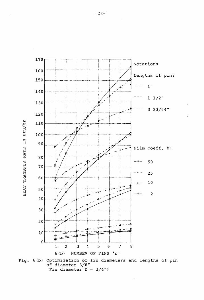
(b) Optimization of Fin Diameters and Lengths of Pin of Diameter 3/8 inch. (Fin Diameter D = 3/4 inch) ••••••••••••••••••••••••••••••••••• 38
7. Experimental Set-up for Measurement of Heat Transfer at Different ,Air Velocities............ 48
8. Location~·Hllmhering Arrangement of Thermocouples at the Ends of Pins ••••••••••••••••••••••••••••• 51
9. Location-Numbering Arrangement of Thermocouples at the Roots of Fins •••••••••••••••••••••••••••• 51

-5-
Page
10. Location-Numbering Arrangement of the Thermo-couples at the Roots of Pins .••••••••••••••••••• 52
11. Location-Numbering Arrangement of the Thermocouples Measuring Outgoing Air Temperature in the Duct ••••••••••••••••••••••••••••••••••••• 52
12. Heater Circuit Diagram ••••••••••••••••••••••••••••• 54
13.
14.
15.
16.
17.
18.
Curves Showing NR Vs. 0 Measured at Constant ~e 0
Heat Supply Rates ••••••••••••••••••••••••••••••• 57
Graph Showing e Va. Heat Transfer Rate of the o
Finned Pin at Constant Reynolds Numbers ••••••••• 59
Graph Showing e Va. Heat Transfer Rate of the o
Plain Pin at Constant Reynolds Numbers •••••••••• 64
Comparison of the Heat Transfer Characteristics •••• 65
Reynolds Number versus Nusselt Number of <the Finned Pin Banks ••••••••••••••••••••••••••••••••••••••• 74
Effectiveness of the Finned Pins with Forced Convection ................................ '6 • • • • • • •• 76

-6-
LIST OF TABLES
Page
APPENDIX A. Fortran IV Program for the Optimization of the Finned Pins ••••••••••••••••••••••• 83
APPKNDIX ~~
I. Measured Heat Transfer Data of the Finned Pins At Constant Heat Input and Varying A.ir Flow.................................................... 84
Table II. Heasured Heat Transfer Data of the 'Pinned Pins Jlt constant Flow Hate and Varying Heat Inputs •••••••••••••••••••••••••••••• 93
Table III. Measured Heat Transfer Data of the Plain Pins at Constant Flo't,! Pate and Varying Heat Inputs •••••••••.••••••.••••••••••••• 94

-7-
I. INTRODUCTION
After the establishment of the fact from the works of
Hsieh(l) and vatsaraj(2) that extended surfaces in the form
of finned pins can improve the rate of heat transfer by as
much as 85 percent with an increase in effectiveness of 61
percent under free convection, it was decided to investigate
the possibility of further increasing the heat transfer rate
by increasing the film coefficient, since the film coefficient
is the main controlling factor in the heat transfer performance
of any heat transfer surface. This film coefficient can be
increased by means of forced convection.
The object of this investigation consisted in finding
the relation between the overall heat transfer coefficient
(which depends on both conduction and convection processes
through the finned pin) and the local individual film
coefficient (which depends on the fluid, its velocity and
other factors), optimizing the variables of the finned pin
extended surfaces and determining the improvement in the rate
of heat transfer.
The general procedure involved was as follows:
a. Designing ductwork to get a uniform velocity
profile at the test section and designing a
device for changing the amount of air quantities
so as to obtain the flow at different Reynolds
numbers,

--8--
b. OptImizing the para."11cters of the fin.ned pin
for forced convection, and
c. Deriving an empirical ~'luation for the film
coefficient in Nusseltlg for the finned

-9-
II. LITERATURE REVIEW
Ever since there was a need. of a heat transfer surface
or a heat exchanger in industry, heat transfer engineers
have been trying to increase the rate of heat transfer
with compact surfaces. For doing so they eMployed various
types of fin geometries and extended surfaces. The growing
demand for air-cooled heat exchangers gave an impetus to
investigate ctnalytically such surfacf"s ~",hich would require
a minimum quantity of metal with compactnes~, be easy to
manufacture, transfer more heat and have maximum effici.ency.
It was realized that all these qualities could not be combined
in an assembly because one requirement would conflict w:i.th
the others. Hence while designing such surfaces the most
desirable requirements were selected over l~ss preferable ones
and the opt:ir.ium quali ties 'i'>lere used.. The study led into
extensive 8xperimental and analytical "fJork and various types
of arrangements were designed. Some arrangements are:
(1) plate fin surfaces: (2) finned tube surfaces with circular
and flattened cross section ern~loying various shapes of fins;
(3) tube hanks with circular and flattened cross sections
having inside an.d outside flow; and. (4) screen and sphere
matrix surfaces. Rays and Isonc1oI'! (8) have. given the design
and the flow friction data for 88 d.ifferent arrangements.
Recently Professor Hsu, with his graduate students, Hsieh
and vatsaraj(22) I introduced a completely new type of extended

-10-
surfaces with finned pins. In this arrangement a a.nnular
fins of rectangular cross section are installed equidistant
on pins small length. If banks of these finned pins are
arranqed and staggered on the heat transfer surface, a large
increase in the rate of dissipation could be obtained with
high effectiveness. In brief f the purpose is tn increase
the area of exten surface without increasing the area of
that part of the primary surface covered by the pins.
IJakob (11) gave a good history of the derivation of the
heat transfer equations for vB.rious fin configurations, which
could be treated analytically. In all these treatments the
heat transfer coefficient is assumed t.O lle uniform or an
average value about the e"tended surfaces is used although
a great variation in the filre coeffic:i.ent is observen.
other assumptions are also made in solving the differential
equations. Harper and Brown(12) first introduced the con cent
of effectiveness of extended surfaces which added another
important point to be considered along with other considerations
in the selection of any arrangement.
Krr:!ith (13) gave the mat,hematical equation for the heat
transfer from a neglecti.ng convection from the free end.
(7) gave a simplified equation for the heat transfe'r
frr)lll a rectangular cross section considering convection
at the and used a correction length to take care of
the end T.:r • i1 p 'f.;f ( 12 ) t t t . f .l'larper an.... ".~ro" n gave .~.IH·~ equa l.ons . or
the the effectiveness of the f:tns. Psieh (1)

-11-
found that the combined finned pin would have characteristics
related to pins as well as the fins and gave a mathematical
eguation in the combined
Avrami and Little(15) found efficiencies of annular fins
for different ratios of inner to outer radii of fins. They
applied a two-dimensional analysis to a flat rectangular fin
and found that a small height to thickness ratio and larger
inner diameter of the fins would he more effective. Hsu(3)
has narrated d.escriptively the d.erivation of various empirical
equations for the forced convection inside small tubes and
outside submerged bodies. Starner and f-1c.Manus (16) found the
average heat transfer coefficient for four fin arrays,
positioning their base at different angl~s, and dissipating
the heat to the surrounding air. They found that similarly
spaced parallel plates would give more heat transfer than
vertical arrays or the plates at any other angle. They also
found that the film coefficient \!voulcl renuced considerably
by reducing three-dimensional flO'\lo1 into two-dimensional flolll1.
Ward and Young(6) studied the heat transfer and pressure drop
of air flow across triangular pi tch banks of fin.netl tuhing
and gave the coefficients for different diameters of tubes,
with different nurrbers of rows and columns.
Y:'I' • 1 :t • .. n ( 19 ) .' . -.~11. (,j.l.ng ana '- oogan measurec: !: .. eat transfer and
pressure loss characteristics of internally finned tubes at
different flow rates. Gardner and Carnavos(18) studl the

~-12--
thermal contact resistance in finned. tubing and found that
contact pressure between the fin and the tube affects con-
siderably the heat removal capability of finned tubing.
They also gave a theoretical method for predicting the gap
resistance between the tube and fin in terms of the fin
tube c!iameters.
Deissler and. Loeffler(17) observed the heat transfer
and the flow friction characteristics of fluids flowing
over surfaces at temperatures up to 2500o~ and velocities
up to a ~~ach number of 8. They employed Von Karman's
expression for the eddy diffusivity in the outer portion of
the boundary layer, vii th variable properties in the suhlayer,
to obtain the friction and transfer correlations for
flow over a plate. ( ">0 ) Theoclitus and Eckrich '-' gave an experimental techniqne
for determining effectiveness of extended surfaces.
Appl and Hung (21) utilized fins of restrict.ed l(:<·nq'th
with individually optimum profiles prescribed minimuIn
clearance between the fins. They gave equation~ for the
nu.."Uber of fins to be used to provid~ the least lTr'~L'Jht o'F
fins for a given surface heat dis::;.:i.Dation.

-13-
III. ~rHEORETICAL INVESTIGATION
Nomenclature
A == Area of pin, sq. ft.
B == A parameter
b :.:= Thickness of fin, ft.
c = p Specific heat of air, Btu/Ibm OF
d == f'Jiampter of the pin
...., == Outside diameter of fin, ft • t"'
= Equivalent diam8ter of bundle of finned pins
d a == Density of air at ta in Ibm/cu. ft.
dh == .'lanome b~~r reading in incht~s of NClter
d == Pressure differential in Ibs/sq. ft. p
9 == Accel?ration 0f gravity
H == Another para.met.cr
h == l\,Verage convect! ve heat transfer coefficient, ')
Htu/hr ft·'-
IO(X)' ll(X) == Zero and first order modified Bessel Function
of 'x', 1st kind
KO (x), Kl (x) == Zero and first order In.o\~i f Bess;:J. '=<'u!1ctiol1
of f x' , 2nd kind
k == Thermal conductivity of finned pin metal, Dtu/hr ft of
k == a Thermal conductivity of air at t a' Btu/hr ft of
I, == Length of pin, ft
m = A variable = 1-4h/kd
N == Another variable == .;- 2h/kb

NN == ~ u Nusselt number := h D /k e a
~ == Prandtl number :: C iJ/k a ~ Pr p
N :: Reynolds number:: u d D /~ Re a e
Q == Heat Transfer rate, Btu/ft2
Ql' Q2' Q3'····Qn == Rate of heat transfer at the root of the
pin with 1, 2, 3, •••• n fins spaced
equidistant from each other.
q == Rate of air flow, cu. ft. per sec.
r 1 == Radius of pin, ft. == d/2
r 2 == Outside radius of fin, ft. == D/2
SL == Center to center longitudinal distance b~tween
consecuti va pins in the direction of f10\;'\1, ft.
ST == Center to center transverse distance between consecutive
pins perpendicular to the flow, ft.
s == Spacing of fins, ft.
t T t f t h OF. a == empera ure 0 a rnosp ere, -
u == Velocity of air, ft/sec
w :: Density of water at t a , Ibm/cu. ft.
a :: T t t th t ~ th f' o~ o . empera ure excess a ~ e roo. o~. .9 1n I ,t
== t - t o a
lJ == Dynamic viscosity of air at t , Ibrn/hr, ft. a
~thematical Equations for the Heat Tran.sfer From a Finn~d p .. !E._
The forced convection equations for the heat transfer
from extended surfaces, in the form of finned pins, can be
derived from the free convection heat transfer equations for

-15-
the same configuration, given by Hsieh(l).
The follo"'wing assumptions are made in deriving these
equation,g:
a. Heat conductio:) in thlF~ pin is one dimensional; i.e.,
temperature over any cross-section of the pin is uniform.
b. The tempera,ture of the ambient air is constant.
c. 'rile thermal conductivity of the extended surface
material is constant.
~rhe annular fin is considered very thin so t.hat heat
loss t.hrough the onter edge t.o the ambient fluid is
neglectec.
e. The heat transfer cOf:fficif,:,rt cv~r tJ"(~ ;~l1.rfacp of
the finne~ pin is consider~~ constant.
botLl cases, tha.t iT'.
But, in the of a rigorous t~eoret
correction factor mc.y bt~ US0(~ '{Ji th 1. 0t1uations ..
Let a sinqle n, having two fins 0n it, he held oerpen-
dicular to the direction of air flow f ~'7i:th an avertvJe film
coefficient: uh I bet'(.ieen the surface I the ~ir. Par analytical
purposes such an assembly may :be divided into sev(~n ptirts and
numbered as shown in Figure 1. The SUD;3(!rii1t(~c quarrti ties in
this section are denoted such that the fi('st subscript indicates
the part being considered the <1econr7 one indicates the va. 1 u.(:-:·
of 'X' as measured from th€: left end of tha't part. The fins
are soldered or brazed on the pin.
The heat flux Q7-0 from pin 7 as given by Kreith(13) is:

-16-
3 6
2 4 5 7
Figure 1 A Pin With Two Fins

tanh me + HI .. ---.~---1 + HI tann me (3-2-1)
where:
t 7- 0 :::: root temperature of pin 7.
tanh me + HI
B2 =: r-+ IT 1 tanh me· (3--2-11\)
The heat flux 06-0 from fin 6, given by schneider(7) is
K1 (Nrl )I1 (Nr2) - I 1 (Nr1)K1 (Nr2) :::: 2n r 1k:lte 6-0 KQlNiJ!I
1 (r~2)--+-I-01Fjrl) Ki-(1\fr 2)
(3-2-2)
where~
t 6- 0 = average root temperature of f
N=r~ kE
IO == ~ero order modified Bessel function, first kind
II == First order modified Bessel function, flrst kind
KO == Zero order modified Bessel function, second kind

-18-
Kl = First order modified Bessel function, second kind
(3·-2-2A)
r 1 and r2
are the inner and the outer radii of the fin.
The heat flux through pin 5, if it "'Jere surrounded by
a fluid, \vith film coefficient hi' could be obtained by
equating the heat flux through the end of pin 5 with the
heat flux through the root of pin 7, thus
Qs-t = Q7-0
giving also
and
e == 95
_0
, at x == 0 (3-2-3)
The value of h. can be l.
found from
Q6-0 == hi
(1l'dt)9 6_0 (3-2-4)
or
(3-2-5)
From the energy balance, the heat flux equation of pin 5
is given in the differential form
where
d 2e 2 dx2 - mi e == 0
I 4h. l.
kd
(3-2-6)

Solving equation (3-2-6) with the help of the boundary
conditions obtained in (3-2-3), gives
cosh m. (t-x) + 112 sinh m. (t··x) 1 ~ 1.
where~
(3-2-8)
In equation (3-2-7), substituting the first boundary condition
from equation (3-2-3) i.e.,
at x = t, e = e = 5-t
the result is:
where:
By differentiating equation (3-2-7) and putting x = 0, we qet~
de dx
x = 0
sinh mit + H2 cosh mit
= - m,' e 5 0 --------.-.'-~.-,~,-------1. .- - cosh t + IT • h t - In]., ~'12 61.n., m._
, 1.
The heat flux through pin 5 can be written as:

'{-.There!
B == 4
-20-
(3-2-9)
The heat flux at the end of pin 4, Q4-b' at x == b is found
by equating it with the heat flux at root of pin 5, Q5-0
and the boundary conditions can he fixed
and
(3-2-10)
where:
9 4- b == The temperature difference at the end of pin 4
at x = b.
The differential equation for pin 4 is:
de I Q4-b =: -kA dx x=b (3 -11)
Equating eq. (3-2 10) and eq. (3-2-11) and after rearranging,
the result is:
d84
_b
--~~---- == -m.B4e~ 0 1, ~,+~ (3-2-12)
?\ryain from the energy lance, the d5 ~r r0ntial equation

for a differential element of a pin is~
20 0 - m - ==
The boundary conditions for pin 4 are~
at x == 0 0 = 0 4 - 0
x = b e = e 4-b (3-2-13)
By using Eq. (3-2-10), the follovlinq solution of Eq. (3-2-12)
is obtained:
e cosh m (b-x) + H3 sinh m (b-x) 0
4--0 == ---'cosi':-- rob +1r;-S1nh -riih----
where: mt
H3 = -- B m 4
(3-2-14)
And the heat flux through the root of pin 4, 04-0' is:
k ". de 04--0 == .r~ dx x == 0
But de I is obtained by differentiating equation (3-2-14) dx x == 0
and putting x == 0, hence
(3-2-15)
The heat flux of pin 2, Q2-0 is obtained in a similar manner
thus!
e e:---2-0
cosh m. (t-x) + 8 4 sinh m. (t-x) 1 1
(3-2-16)

-2
where:
and tanh rob + II]
= ---,----, 1 + H3 tanh rob
Hence,
(3-2-17)
where: tanh
==
The heat flux of pin 1, 01-0' is analogous to equation (3-2-15)
and can be written as:
where:
and
tanh roa +
tanh ma + HS
1 + lIS tanh rna
H m. B 5 =--1:. 8
m
(3-2-18)
The equation of heat transfer for the finned pin with any
number of fins can be found by generalizing the above equations.
For doing so, it is assumed that all fins <l.re equally spaced
i.e., a = b c = s. If L is the length of pin and n

-23-
is the number of pins of t thickness, then
Let
and.
L - nt S == n + 1
T := tanh ms
T. ::: tanh m.t .1. J.
where m and m. are given by equations, l.
m ==
m. == .1.
and where
.r--"4h kd q
rtrh!" kd
(3-2-19)
(3-2-20)
(3-2-21)
(3-2-22)
(3-2-23)
(3-2·-24 )
are given by equations (3-2-2A) and (3-2-1A)
respectively.
In general, the heat transfer equation for the finned
pin with n number of fins can be written as:
(3-2,-25)
where B is a coefficient parameter found for the finned pin p
having n number of fins on it.
found to be BIO for n == 2.
In equation (3-2-18) B was p
"Now the follot4ing equations with variable subscripts
within the parentheses indicate the general equations with
which parameter Bp is found. The equations (3-2-26) to
(3-2-29) if repeated in sequence, from n == 1 to n == n, will

-24-
give Bp as B(4n+2). These equations are:
H(2n) = .!'2-B m. (4n-2)
1. (3-2-26)
B(4n) = Ti + H(2n)
1 + Ti H(2n) (3--2-27)
= (3-2-28)
B(4n+2) = T + H(2n+l)
1. + T H(2n+l) (3-2-29)
Thus, for example, for n = S, Bp = B34 and will be found
when values of the parameters II and B are found in sequence,
starting from n = 1 to n = 8 in equations (3-2-26) to
(3-2-29).
Application of the Mathematical Equation
of Heat Transfer From a Finned Pin, to
Free and Forced Convection Conditions.
In the section on Mathematica~ Equations for th~ Heat
Transfer ~ ~ ~~nned Pin, the general equation for the
heat transfer from a finned pin is given. This equation is
applicable to natural convection if the va.lua of the film
coefficient h is found for natural convection conditions.
MCAdams(9) gave the form of the equations for the film coeffic-
ient h for horizontal pipes in air at room temperature and
at atmospheric temperatures for different ranges of Grashof
-25-
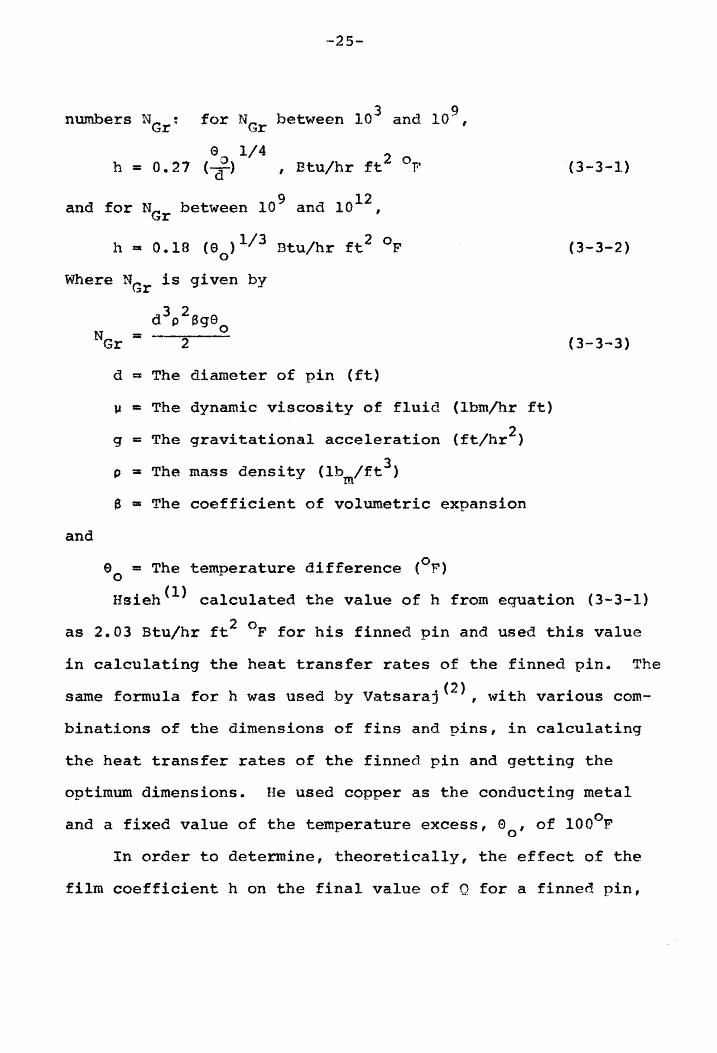
numbers NGr ;
9 12 and for NGr between 10 and 10 ,
h a 0.18 (90
)1/3 Btu/hr ft2 OF
Where NGr is given by
and
d 3p
2 ag9o N == -- " Gr "
d = The diameter of pin (ft)
p == The dynamic viscosity of fluid (lbm/hr ft)
q == The gravitational acceleration (ft/hr2)
p == The mass density (lb Ift3 ) m
e == The coefficient of volumetric expansion
90
m The temperature difference (op)
(3-3-1)
(3-3-2)
(3-3-3)
Hsieh(l) calculated the value of h from equation (3-3-1)
as 2.03 Btu/hr ft2 of for his finned pin and used this value
in calculating the heat transfer rates of the finned pin. The
same formula for h was used by vatsaraj(2), with various com-
binations of the dimensions of fins and pins, in calculating
the heat transfer rates of the finned pin and getting the
optimum dimensions. He used copper as the conducting metal
and a fixed value of the temperature excess, 00' of lOOoF
In order to determine, theoretically, the effect of the
film coefficient h on the final value of Q for a finned pin,
--26-
values of h are varied in the equations given in the section,
f.vIa.themat~~! Equati.ons f~ the Heat Transfer FroE. ~ !:inned
Pin, keeping fixed values of 90
, k, d, D and t. A graph of
such calculated values is shown in 'r.'il'jure 2. From the curve
it can be readily seen that at smaller values of the film
coefficient, such as at h 2 0 = 20 Btu/ft hr F, the increment
in the heat transfer rate for a given increment in the film
coefficient h is more than the increments at higher values
of h, such as at 150. Of course, the value of Q goes on
increasing with h, but the decreasing slope of the curve at
higher values of h shows that the effectiveness of extended
surfaces drops very rapidly. For example, \vhen the value of
film coefficient h is increased to ten times its natural con-
vection value, the increase in the heat transfer rate is
approximately four times, but if this value of h were increased
50 times, the increase in the heat transfer is hardly ten times
that obtained in free convection. Hence, for a small increase
in h, substantial increase in the heat transfer can be obtained
without appreciable loss of effectiveness. Before making any
conclusions from this section it is necessary to determine the
limitations of such a proposition and to optimize various
parameters involved in the heat transfer from a finned pin.
~£timization of the Parameters Involved A~!he
Heat Transfer From a Finned Pin
In the equations for the heat transfer from a finned pin
the following variables \~l~~re involved:

240'
200 J..i
..c: ""-::;$ +J co z 160 H
.. 0 .. fit 120 8
~ p::; V fit f:r.I {/J
Z 80 ~ 8
8 ~ ~ 40t IF FREE CONVECTION ::c:
o 20 40 60 80 100 120 140 160
FILM COEFFICIENT 'h' IN Btu/ft2hr OF
Figure 2 Variation of Heat Transfer Rate with Film Coefficient. Computed at o = lOOOF
o
t t\.) ...., . I

h - film coefficient
d - diameter of pin
D - diameter of fin
-28-
k - thermal conductivity of metal
t - thickness of fin
1 - length of pin
n - number of fins
s - spacing of fins
The last variable can be eliminated by using the three
variables mentioned immediately before it, i.e., t, I, and n.
Hence there are seven variables which playa vital part in
the heat transfer equations. It is very difficult to
eliminate five variables in order to get an optimum value
from the remaining two variables without ignoring the effect
of any eliminated variables on the ultimate result.
A Fortran IV program was run on the IBM 7040 computer
to compute the heat transfer with seven variables. Some of
the most practicable values of these variable parameters were
used to determine their effects on the heat transfer of a
finned pin. The program is listed in Appendix A. From the
results obtained, the heat transfer rates were plotted against
the number of fins, for given lengths and diameters of the
pins, and for given thicknesses and diameters of fins.
a. These rates are calculated for two different
metals, copper and aluminum, having values of

-29-
thermal conductivity of 220 and 132 Btu/hr, ft, of
respectively. Figures 3(a) and 3(b) show the effects
of thermal conductivities on the heat transfer for
different ranges of the film coefficient h. It is
noted that the heat transfer through copper is more
than the heat transfer through aluminum, as was
expected. The difference in the heat transfer rates
is considerably higher at higher values of h, such
as 50 Btu/hr ft2 0p. Therefore, if forced convection
with higher values of film coefficient is employed
the material with higher thermal conductivity, that
is, copper, should be preferred to obtain the most
desirable effects. For the same reason, in this
investigation the value of thermal conductivity used
is 220 Btu/hr ft of.
b. On Figures 3(a) and 3(b), different sets of graphs
are drawn - one plotted for 0.01 inch thickness
of the fin and the other for 0.020 inch. It is
noted that by increasing the thickness of the fin,
the heat transfer rate decreases, hence, as thin a
fin as possible should be employed.
The following deductions are based on figures 4{a),
4(b), 4(c), SCa), 5(b), 6(a), and 6(b).
c. With an increase in the length of pin there is
always an increase in the rate of heat transfer.

24
22
20
,... 18 .c: .......... ::s +J 16 ~
Z H
.. 14 01
~ 12 8
~ ~ 10 ~l ~ til
~ 8 8
8 < 6 ~ ::r:::
4
2
0
-30-
d = l/S", D = 1/4", L = I"
I i l
i i /~ ·---t-~~-l
./! . ; 1% 1
I ' ~
1--.. _--+-+-- .. -~-.+----.-.---'--.~+-.-~ ota t ions /1 ! ; ,
/ I I I ! I ~ .ilmcoeff. h: ---1---'--1-- -----.--+---~-+-
i :~' ! ~~ I I -6- 50
i~"" I 1
~ i --+ -~ ... -----f _. I I \
/: ' , ',/' 1 I I -e- 25 Ai: : ........... ~---+-,~~ .. -~--.-+-- ... ----I--.--+------+-..",...... ..... , I
1 2
3 (a)
! ,L---- -x- 10 ! ~ - *"-~ -1r -- I
-G>- 2
3 4 5 6 7 8
NUMBER OF FINS 'n I
Fig. 3(a) Optimization of thickness and thermal conductivity of fin metal t = 1/100"
(Continuous lines showing k = 220 Btu/ft hr OF, discontinuous lines k = 132 Btu/ft hr OF)

24
22
20
,... 18 .c:
" ::t +J 16 III
z H
.. 14 01
~ 12 8
~ et:: 10 ~ ~ U)
~ 8 8
8 ~ 6 j:il :z:
4
2
0
·-31-
d = 1/8", D = 1/4 n, L = 1"
1 2
3 (a)
3 4 5
NUMBER OF FINS
-A- 50
-.- 25
-lC- 10
-<i>- 2
6 7 8
'n I
Fig. 3(a) Optimization of thickness and thermal conductivity of fin metal t = 1/100"
(Continuous lines showing k = 220 Btu/ft hr OF, discontinuous lines k = 132 Btu/ft hr OF)

,,·32"-
170 otations
160 engths of pin:
150 1"
140 +- 1 1/2 If
130 3 23/64"
s..., ..c 120 " ::::1 +l
110 m Film coeff. :z H
100 -/A- 50 ... Cl
~ 90 • ~ t "".-~.--- -.- 25
8 ~ 80 ~
! W~ •• ___ ~ __ ~~_
-l(- 10 c:r:; r£l 70 Ii.! -0- 2 Ul
~ 60 -
8
8 50 < ~ :r:
40
30
20
10
0 1 2 3 4 5 6 7 8
4(a) NUMBER OF FINS In'
Fig. 4(a) Optimization of fin diameters and lengths of pin of diameter, 1/8" (Fin diameter D = 1/4")
h:

-33
170 Notations
160 ~-r- Lengths of pin:
150 ~---- 1"
140 t .. - 7 -------+--"- 1 1/2"
130 1-- j- .- .- - -.- 3 23/64" I
I So-!
120 ..c
" ::; +l t!l 110 Film coeff. h: z H
100 -- -t ~,.---~---.~ -ex- 50 -a
90 .-- ~-+-------------- .. 25
t:Ll 8
~ 80 - 1.- 10 ~ riI
70 2 ~ -0-
CI)
z ~ 60 8
8 ~ 50 t:Ll ::x::
40
30
20
10
0 1 2 3 4 5 6 7 8
4(b) NUMBER OF FINS 'n '
Fig .. 4(b) Optimization of fin diameters and lengths of pin of diameter, 1/8" (Fin diameter D = 1/2" )

170
160
150
140
130 H
..c: "'- 120 ::s ~ al
z 110 H
.. 100 01 .. ji:j 90 8
~ ,:r; 80 JJ.:I ~ 70 Ul ~
z ~ 60 E-4
E-4
~ 50 :x::
40
30
20
10
0
-34-
! I I I i 1 i i
! ! I ! i
!
I i
I
! I I
I !
i I
I
i i
] ! ! I
I i ;
I
j I
i : !
i I· I ! I
I ,
i i I
L ~-+---
i I I
j i ( I
: I
,
i ;
I I I
i I ~V
i I
~ ,-. i ~ _ ... t_~-='-" ! iV~ I i/ -f .... - J __ -,
I .... "" 1 ! ~ - - _.... .-4
/t~ ~l _- .. -~. -'f j.--
~ ,~~~ ~_r.~ ~ ::.- . -r I _ • -$"- '_-:1 . -- --
~1 ~ ~-1'-- : -+ .~ ':'_~ --- I . .-..;--- -' -' -' I I
~ I ....... I , ~~ .. 1 - • -1, •
1rI-...._--~
~.....-- T
1 2
4 (c)
3 4 5 6 7 8
NUMBER OF FINS 'n'
Notations
Lengths of pin:
-In
----1 1/211
-·_·3 23/64"
Film coe • h:
-~- 50
-. - 25
-x- 10
-(1)- 2
Fig. 4(c) Optimization of fin diameters and lengths of pin of diameter. 1/8" (Fin diameter D = 3/4")

170 Notations
160 I
Lengths of pin:
-+ I
150 ---+---I i I- I" I
I 140 ~---i--- ----- ---
I 1/2" 130
3 23/64"
120 ~
..c::: "- lID
:=:$ 4J m 100 z coeff. h: H
~ 90 8
50 ~ 80 p::; 25 ~ ~ 70 UJ z 10 ~ 60 8
8 2 < 50 ~ ::r::
40
30
20
10
0 1 2 3 4 5 6 7 8
5 (a) NUMBER OF FINS In'
Fig. S (a) Optimization of fin diameters and lengths of pin of diameter 1/4ft (Fin diameter D = 1/2")

170 otations
160 engths of pin:
150 -----4----~
I" 140
1 1/2" 130
3 23/64"
120 f..I
..c:: "- 110 ~ +J ~ 100 z ilm coeff. h: H
jJ;:l 90 8 50 ~ p::; 80 jJ;:l 25 j:l~ 70 CI)
~ 10 8 60
8 2 ~ 50 t:il ::t:
40
30
20
10
0 1 2 3 4 5 6 7 8
5(b) NUMBER OF FINS r n'
Fig. 5(b) Optimization of fin diameters and lengths of pin of diameter 1/4" (Fin diameter 0 = 3/4")

170
160
150
140
130
120
H ..c: 110 ......... :;j +J 100 o:l
Z H
90 ~ 8
~ 80 p:; ~ ~ 70 U)
z ~ 60 8
8 SO ~ ~ !I!
40
30
20
10
0 1 2
6 (a)
-t----+---r--.-+----I No ta t ions
Lengths of pin:
1"
1 1/2"
3 23/64"
Film caeff. h:
-8- 50
25
-li.- 10
-0- 2
3 4 5 6 7 8
NUMBER OF FINS 'n r
Fig. 6(a) Optimization of fin diameters and lengths of pin of diameter 3/8" (Fin diameter D = 1/2")
f-t ..c:
" ~ 4J c:o z H
!:LI 8
~ p::: til ~ Cf)
z ~ 8
E-1 r< J;:.4 ::r:
170
160
150
140
130
120
110
100
90
80
70
60
50
40
30
20
1 2
6(b)
3 4 5 6
NUMBER OF FINS
Notations
Lengths of pin:
In
1 1/2"
3 23/64"
Film coeff. h:
-A- 50
25
-x- 10
-G;l- 2
7 8
In'
Fig. 6(b) Optimization of fin diameters and lengths of pin of diameter 3/8" (Fin diameter D = 3/4 ft
)

-39-
However, for a given number of .fins, the increment
in the rate of heat transfer with increase in the
length diminishes grad.ually as the value of the
film coefficient increases. Beyond a certain value
of the film coefficient, increasing the length of
pin reduces the rate of heat transfer.
d. With an increase in the diameter of the pin there
is an increase in the rate of heat transfer of the
finned pin.
e. With an increase in the outer diameter of the fin
an increase in the rate of heat transfer of the
finned pin is observed. However, when a fin of
both larger outer and inner diameters is usell, the
increase in the heat transfer is not noticeable,
especially for small values of h. At higher values
of h, however, the increase in the rate of heat
transfer is pronounced.
f. with an increase in the namber of fins there is an
increase in the rate of heat transfer of the finned
pin. It is noticed that for a given value of the
film coefficient h, increasing the number of fins,
for a given length of pin, increases the rate of
heat transfer of the finned pin. The increment
in the heat transfer rate with an increase in
number of fins reduces as the number increases.

-40-
g. The cumulative effect of increasing the length of
the pin and the number of fins is that the rate
of heat transfer of the finn~d pin will be increased.
According to paragraph c, beyond a certain value
of the film coefficient h, the rate of heat transfer
decreases with an increase in the length of pin.
The combined effect will be that the rate of heat
transfer will decrease beyond a limiting value of
the film coefficient h. The larger the n~er of
fins the smaller will be the limiting value of
film coefficient h. Hence, for a certain combination
of the length of pin and the number of fins, the
rate of heat transfer increases with the film
coefficient h only within the limiting value of
film coefficient h.
From the last paragraph it can be seen that for maximum
effectiveness, an optimum rate of heat transfer should be
chosen within the limiting value of the film coefficient for
the given extended surface.
We realized that by increasing the diameter of the pin,
the weight of material used is increased in proportion to the
square of the diameter, hence, the diameter of the pin should
not be increased to a great degree.
In view of these factors, the dimensions of the extended
surfaces for the experimental investigation were chosen as,

-41-
d = 3/8 in.1 D = 7/8 in.; n = 8; and the optimum rate of heat
transfer as 55 Btu/hr at the film coefficient h = 10 Btu/hr
ft 2 of.
Dimensional Analysis for Convective Heat
Transfer Coefficient in Forced Convection
The derivation for the form of the equation for the film
coefficient h for forced convection over a finned pin is based
on the dimensional analysis suggested by Hsu(3) for forced
convection inside tubes. In the present investigation, forced
convection over extended surfaces in the finned pin enclosed
in wind tunnel may be considered similar to forced convection
in the small diameter tubes because of the absence of a free
stream velocity and a free stream temperature due to the great
obstruction of the pins. Hence the form of the empirical
equation for the film coefficient will be similar to Nusselt's
equation.
The functional relationship between the film coefficient
h and other factors can be expressed in the following form:
h = C aOb ekd m n u 1.1 P c p (3-5-1)
where:
u == The velocity of fluid
D = Diameter of pipe or the length of plate
k == Thermal conductivity of the fluid
c = Specific heat of the fluid p
1.1 = Dynamic viscosity of fluid
p == Mass density of fluid
c == A constant

-42-
The above quantities are expressed in the fundamental
dimensions, i.e., L for length, T for time, M for mass,
e for temperature, and H for energy, which can be replaced
by (force) x (distance) or
L 2 -2 H ::: (M:r) x (L) ::: ML T T
Other quantities can be expressed as follows:
U ::: LT-1
D == L
p == j\1:L-3
= 11M- I e -1 == L2T,-2e-1 cp
-1 -1 J.t = ML T
-? -1 -1 -3 -1 h = HL -T . e = MT e
k == HL-lT-1e- l == MLT- 3e-1
(3-5-2)
(3-5-3)
By substituting these quantities in equation (3-5-3),
the result is
MT- 3 e-1 == (LaT-a ) (Lb) (McL-cT-c ) (MdLdT-3de-d)x
(~L-3m) (L2nT-2ne-n) (3-5-4)
In order to balance equation (3-5-1) dimensionally,
equation (3-5-4) should yield the following values of at h,
C and d in terms of m and n.
a == m
b l1li m-1
c == -m + n
d == -n + 1

-43-
With the above values of the exponents equation (3-5-1)
becomes:
or
or
,_ C m-m-l -m+n L -n+l m n n = .. u D lJ !":- P C
u D men :: C (--p-) (.-PJ:.)
11 k
P (3-5-6)
(3-5-7)
(3-5-8)
If throughout the experiment Npr is kept constant, then:
(3-5--9)
For the finned pin bundles enclosed in a wind tunnel,
equation (3-5-9) will be derived more appropriately by
assuming a relationship of active
form suggested by and Young(6)
T,hese factors are:
D .- Outer diameter of the fin
d - Diameter of the pin
s - Spacing of the fins
t - Thickness of the fin
Npr - Prandtl nu~ber
The relatior~hip ·
c (~)-d (!)-e s t
involve(~ in a
finned tube arrays.
(3- 10)
b, c, d l , and re arbitrary exponents ~n~ , is a

-44-
constant. Values of these constants given by Ward and Young(6)
for a seven array tube hundle, or more, are:
A == 0.364
b = 0.68
c == 0.45
d1 == 0 .. 30
e = 0.30 (3-5-11)
If a correction factor Kl along with constants given
in equation (3-5-11) is used in equation (3-5-10), an
empirical equation can be derived which would represent an
equation for the finned pin arrays.
By using the value 0.74 for Npr and actual values of
D, d, s, and t from the experiment, equation (3-5-10) can
be reduced to:
N == K ( 120) (N )e684 Nu 1· Re
CharacteFistic Length and Reynolds Number
for the Flow Across theFinn~d Pin Banks.
(3-5-12)
In calculating the rate of heat transfer for turbulent
flow across the finned pin bundles, the concept of EQUIVALENT
DIAMETER, or the characteristic length given by Hsu(3), is
used. While deriving an empirical equation in the previous
section for forced convection over an extended surface in
the finned pin form (Equation (3-5-9» the diameter of the
pipe, or the characteristic length was not defined. But
the final equation did involve the Reynolds number, ~vhich

-45-
depended on the characteristic length or the equivalent
diameter. The relationship for the Reynolds number is given
by
(3-6-1)
where:
Hence
p - The mass density of the fluid
~ = The dynamic viscosity of the fluid
U a The mean velocity, based on the cross-sectional m
area available for the flow of fluid in the bundles.
De = The equivalent diameter of the finned pin bundle
4(free cross-sectional area) = wettea perImeter (3-6-2)
The free cross-sectional area is given as:
SLST - i d2
(3-6-3)
where:
SL = Longitudinal center to center distance of pins.
ST = Transverse center to center distance of pins.
If Af is the free area available in sq. ft., and q is
the quantity of fluid flowing in cu. ft./sec. then:
u = A~ ft./sec. (3-6-4) m f
With these values known, the Reynolds number can be
calculated by Equation (3-6-1).

I~,T • EXPERI~I(ENT}\I, INVESTIGATION ------------ -
The object of this investigation was to find the heat
removal capability of the finned pin at different flow rates
of air.
After building the apparatus, the first step in the
experiment was to find the rates of heat transfer from the
finned pins, a.nd from the plain pins at various P..eynolds
numbers. Next, it is desired to compare the heat transfer
rates from nnad pins with that obtained from the finned
pins under natural convection conditions and with the heat
transfer rates of the plain pins at oifferent flow rates.
Finally, it is desired to write an empirical equation for
the film coefficient in Nusselt's form.
AEparatus and Tes:t: Rguipment::.
Desis:n. of ,the Wind Tunnel and M~~!P9: ECl.l.!!Ement-!. The
apparatus in this investigation consisted of a heat exchanger
in the form of a box :tn which heat flow is restrlcted
through two surfaces. The edges of the heat. box were
insu1:ated by means of asbestos sheets. The extended. surfaces
consisted of finned pins, staggered in banks. The optimi-
zation of dimensions and the spacings of the fins and pins
f hi i 1 d b t · (2) or t s part eu ar case was one .y Va sara] •
Te~ting Egp.i,Ement. The test equipm.ent for investigating
the effect of forced convection on heat transfer through

extended surfaces with finned pins comprised of a wind tunnel
designed to produce a. uniform velocity profile immediately
prior to the test section. Sincp the transfer of heat was
from both of the heat box, it was considered necessary
to provide separate flow sections for bot.h surfaces, which
'VIas done by partitioning the sheet M.etal duct. }.\n overall
view of the equipment is given in Flqure 7.
The entrance section of the duct was dssigned essentially
in the shape of a diffuser. The optimization of the dimensions
of the diffuser was according to empirically derived relations
for optimum recovery suggested by Kline, Ahbott, and Fox(3)
for a straight-walled diffuser.
After correlating two-dimensional, conical, and annular
geometries, Kline, Z\.bbott, and Fox gave the fol1o~"ing
conditions optima for the diffuser:
a. Minimum loss of total pressure for a given pressure
rise.
b. Maximum pressure recovery for a given area ratio,
regardless of length in the f10TI1 reqion.
c. Optimum recovery is to be obtained for a given length
in the direction of flow.
d. For the given inlet conditions, opttmum recovery for
any possible geometry is desired.
For this investigation the optimum recovery for a given
length (see c above) was considered since the length cannot. he

TEMPERATURE RECORDER TEST SECTION THERMOMETER MICROMANOMETER
~/uIFFUSER
OTOR S BLOWER
CRATES
SCREENS
WORK
TRANSFORMER
Fig . 7 Experimental ee t - up for me surement of heat tr nsfer &t different air velocities
i ~ CO I

-49-
increased beyond limits. The maximum actual pressure recovery,
as a function of twice the diffuser-divergence angle will
occur only when the rate of increase of losses becomes large,
that is, after the average amount of stall in the diffuser
begins to increase rapidly. Thus optimum recovery is obtained
as angle is increased at constant ratio of length and
entrance throat width. By keeping above ratio at about 5.5
and 26 as 11.4, head loss due to dissipation is hardly 11
percent, actual pressure recovery is as high as 75 percent,
and the pulsations are minimum, with the flow regime kept
in the region of no appreciable stall. Thus the dimensions
of the diffuser designed were 30 inches long, 3-3/8 inches by
5-1/2 inches at one end and 6-3/8 inches by 5-1/2 inches at
the other end.
Straighteners are provided in the form of egg crates.
Width to length ratio for egg crates was kept 1:6 for most
effective results. Two sets of screens were provided to
finally ensure breaking away of any large eddies into uniform
flow.
The quantity of air flow was measured at the suction
side of the blower by means of a 3 inch standard nozzle. A
micromanometer was used to measure the pressure differential.
The length of straight pipe for suction was 10 d or 30 inches
and pressure taps were located according to AS~E specifications
(Article 26, Flow Measurement, Part 5, April 1959).
The finned pin heat box assembly used was the same which

-50-
was made and used by vatsaraj(3) for his experiment on
optimizing the dimensions of finned pins for free convection.
One-half-inch-thick asbestos sheets were used around the
edges of the heater for insulation.
In order to control the quantity of flow a special
multi vane-type butterfly valve was fabricated in the
Mechanical Engineering Department of VPI. Final check of
velocity profile was done by means of a hot wire anemometer.
As expected, the velocity profile was fairly uniform in both
sections. Finally the temperatures at different sections
of the heat exchanger were measured by means of copper
constantan thermocouples and a strip chart recorder which
read and recorded thermogenerated voltage in millivolts.
Construction of the Thermocouples. Forty-five thermo
couples were installed at different locations of the testing
section. Of these, 12 were located at the roots of pins, 18
at the roots of the fins, 10 at the end of pins, 4 at the
exit section immediately after the heat box, and 1 at the
fin for measuring the steady state temperatures. The
arrangement and locations are shown in Figures 8, 9, 10,
and 11.
Three connectors with 16 pins each ~;lere used to connect
16 thermocouples to the recorder, which facilitated the
selectivity of measuring the temperatures of particular
locations on the extended surfaces.

:... ......
An t1.rrangement of numbering locations of whioh temperatures he.ve been noted 1n Append1x B
(Figures 1n parentheses Indlc~te thermocouples on the other side of the plate)
27(32) 25 (:30)
I +. - I -I
I i
+ I
- _. " 1- - - ~. - - 1---
1 ~ -. -- ~ I ,-- (17) 1-' 1--
I i
19
~
-- - - ~
- - ,--
---l-
I 9 10 II 12 13 14 15 16 I
8 7 6 5 4 3 2 1
28(33) 26('31)
Fig. a Thermooouples on end of pins (direction of flow being from right to lett)
24(29)
I
I I
+ - - -- - --- i - ~ ... t--I
I I I I I I I I t ~ _. " ~ I- i -- r- t-
I I I I I I I I
Fig. 9 Thermocouples on root of fins (direction of flow 1s perpendicular to the plhne of paper)
I I - I-
I I
I U1 !--I I

3/8
..-..---+: 2iA3 ---i \ T ! \
\\.34 (40) , 4 1/8
~ ~21/8
~35(41)
:±T(~) \44) -, 8 '-H(~)
-~--------\---.~------tII ....
i 17/8 I I I +~
3/8
\ \
\
F1g. 10 Thermooouples at the root of pins noted in Ap:endix B (Direction of flow being from left to right. Figures in parentheses ind!. te thermocouples on the other side of the plate.)
i ~ 13/8 i
1! 5
1/2 \ 4
~ 1
~-J~---~ .. ~-----+- 91/4 I i
,\22
\~
-------- J Fig. 11 Thermooouples measuring temr:ert'tures ot
outgoing a.lr, noted in Appendix B (Direction of flow being perrendiculer to the pl~ne of paper.)

-53-
The thermocouples at the roots of the pins were installed
by silver solder. But the thermocouples at the roots of fins
could not be soldered because the surface temperature of the
pin could not be increased sufficiently due to excessive
heat transfer. Hence, they were attached by drilling a small
size hole, putting the thermocouple junction into it, and
holding it firm by tapping around the hole with a punch.
The thermocouple on the fin was attached by soft solder.
For measuring the average temperatures at the roots of the
pins both in finned pins and plain pins, the thermocouples
were connected in parallel.
Calibration of the Instruments. The millivolt recorder
was calibrated by means of a standard potentiometer. Voltages
in I, 2, 3, 4, and 5 millivolts were fed to each of the 16
junctions of the recorder by means of the standard potentio
meter; and readings were recorded. If any of the 16 points
showed deviation on the chart, correction adjustment was
made.
A 3-inch standard nozzle with the standard ASME
calibration curves was used as the diffus.er.
Cireui t Diagram for the EXEeriment.~ The circuit diagram
for the test of the heater is shown in Figure 12. A current
transformer was used to double the range of the wattmeter.
A voltmeter and an ammeter were connected in parallel and
in series, respectively, between the wattmeter and the heater.
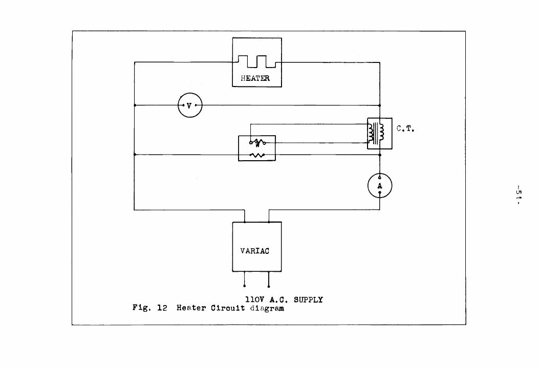
HEATER
VARIAC
110V A.C. SUPPLY Fig. 12 Hes.ter Cirouit diagram
c. T.
lT1 ......

This arrangemen.t gave pow~~r in'put in \-latts free of
losses in the 'i,vattmeter. wattmetl?~r facilitated. in
getting beat inputs into • :"f lreCl in caui:ionlng
aqain;;:3.!': ()i'":

-56-
Test Procedure
The heat box was placed inside the wind tunnel and
the power circuit was switched on. The blower which was also
started, forced the air into the wind tunnel and through the
finned pins on the heat box. For each reading several hours
were required to reach the steady state conditions at the
roots of the pins. The pin-root temperature noted on Table I
of Appendix B was determined by taking the average of the
values of E.M.F. of the individual thermocouples numbered
34 to 45 shown in Figure 10, 't'ihile the pin'-root temperature
noted in Tables II and III ofA.ppendix B was found from the
values of the E.M.F. of the averaging thermocouples. The
rate of air flow was measured by the pressure differential
indicated on the micromanometer.
First, the relationship of the Reynolds number and. the
root excess temperatures was determined at constant heat
supply by varying the air flow by means of the baffle valve.
Five to six readings were taken for each heat supply rate.
The temperature readings of locations Nos. 1 to 45, shown
in Figures 8 to 11, are given in Table I of Appendix B. The
curves showing the relationship of the :R.eynolds numbers
versus temperature excess are shown in Figure 13. Next, the
root excess temperatures at different heat supply rates were
measured by keeping the flow rate constant. ~ curve showing
the heat transfer rates versus temperature excess at the

rs., 0
~ .,...,
0 (!)
J:il CJ t-,:. f!' ~~ cr. PC! Ii.! ~< H 0
r:t:I ex; ...... ' ....... 8 ~ ~ ~ P. lite:"" -':.,
r:t:I 8
7-
140
Notations:
120 e. 1320.0 Btu/hr
)l 998.0 Btu/hr
100 0 656 .. 0 Btu/hr
8 372.5 Btu/hr
80
60
40
20
oL-------~------~-------L------~------~------~ 2000 4000 6000 8000 10000 12000
Figure 13.
REYNOLDS :IUHBER 'N ' Re
Curves Showing NR vs. 0 Measured at e 0 Constant Heat Supply Rates

-58-
root of the pin is shown in Figure 14. The measured data
are recorded in Table II of Appendix B.
List of Apparatus
The following apparatus obtained from the Mechanical
Engineering Department of Virginia Polytechnic Institute
was used.
Ammeter: A.C. 0 to 10 Amps. Weston Instruments Model
1554 177289.
Wattmeter: 0 to 1500 Watts: Maximum volts 400, resistance
ohms 22476, maximum amps. - 7.5; rated amps. - 5; by Daystrom
Inc. Weston Instrument Div. Newark.
Voltmeter: Model no. 912 weston. Range 3 to 300 volts
and 3 to 1000 volts A.C. type.
Variac: Type W 20 MT 3 Variac Transformer manufactured
by General Radio Co., Concord, Mass. Line voltage 120
50-50 cycles per second. Load 0 to 140 v. 20 amps.
Current Transformer: Weston current transformer Model
461 *22278, type 5; Capacity 15 VA. Frequency 50 to 500 cps.
Line voltage 120.
Potentiometer Recorder: Model No. 153 x 62- Vl6- II-III
- 23. Instrument no. 922805, Serial no. 5451: Range 0 to
5 MV, manufactured by Minneapolis-Honeywell Reg. Co. Brown
Instrument Division, Philadelphia, Pa.
~ Wire ,Anemometer: Range 0 to 20,000 fpm. Hastings
Precision Airmeter. Model B-l6A, Serial no. 135. Manufactured

$.1 ..c.:
" ~
3200
2800
2400
rt 2000 z ~
~ 8 ~ 1600
~ P'-1 r.x" tf.l
~ 1200 Eo;
~ ,:~ £':tl ::r::
800
400
0
Figure 14
------+----.............J'~--__;
Notations:
-&- N = Re 9550.0
-7- N =: Re 8660.0
-+- N ::::: Re 6150.0
-&- N ::::: Re 4120.0
20 40 60 80 100 120 140
TEMPERATURE DIFFERENCE 90
IN OF
Graph Showing e vs. Heat Transfer Rate of the Finned Pin at ConstantOReyno1ds Numbers

-60-
by Hastings-Raydist Inc., Hampton, Va.
M~cromano~eter: Trimount Instrument Co., Chicago Ill.
a - 6360 Serial. Reading 1/10,000 of an inch precision.
Nozzle: 3-inch Standard Aluminum Nozzle according to
A.S.M.E. specifications.
Motors and Blowers: . ..
used:
1. General Electric Co. A.C. Motors Model 5 KH 43
AB l060AX type RH, single phase, R.P.-I, 60 cps
AmPS.-l.Oi Volts - 115 V; R.P.M. - 1725. No. TB
2465 with Blower manufactured by American Blower Co.,
Detro! t, 1>~ichigan.
2. A.C. Motor Service B. Winding SPL-PH. Frame-ISIs
H.P. 1/20i R.p.r·1. - 1725; Volts - 115: .t\mps. - 9;
60 CpS.1 Single phase: Serial no. 4503114B,
manufactured by Johnson Fan & Blower Corp. Chicago,
Illinois.
List of Materials
During this investigation the following materials were
Heat Transfer Box with Extended Surfaces. Made by
vatsaraj(2), for which he used material as follows. Copper
rods of 3/8 inch diameter were used for making the pins
of the finned pins. Copper foil of 0.01 inch thickness was
used for making the fins. Copper plate of 1/4 inch thickness
was used for making the front and side plates of the heater
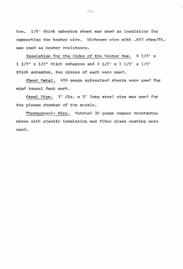
box. l/S n thick asbestos sheet was used as insulation. for
supporting the heater wire. Nichrome wire with .652 ohms/ft.
was used as heater resistance.
Insulation for the Sides of the Heater Box. a 1/2 H x
1 1/2 u x 1/2" thick asbestos and. 4 1/2H x 1 1/2H x 1/2 u
thick asbestos, t'tvO pieces of each ,·:rere used.
Sheet Metal. *20 gauge galvanized sheets were used for
wind tunnel duct work.
~~eel Pi 12e!~ 3 t1 dia. x 3' long stee 1 pipe was used for
the plenum chamber of the nozzle.
Thermocoupl~ Wire. l\1atched 30 gauge copper constantan 1\ ._ ... -..{,._..' •
wires with plastic insulation and fiber glass coating were
used.

-62-
v. DISCUSSION
Discussion and Experim~~l Accuracy
The temperature data obtained for the roots of the pins
showed variation from one row to the other and there was a
variation from one column to the other. This temperature vari-
ation was highest when the temperature difference was greater
and when the flow rate was low. The temperature of the first
column was less than that of the last column. Similarly the
temperature of the upper row was lower than the temperature
of the bottom row.
The temperatures at the roots of the fins in one section
of the wind tunnel differed from the temperatures at the simi
lar roots of fins in the other section. This was due to unequal
gap-resistances of pins in two different sections. Maximum
variation observed was about five percent.
The data obtained from the power supply apparatus, the
temperature measuring instrument and the flow measuring
instruments employed in this investigation were reproducible.
The temperature near the testing equipment was found to
be slightly higher than the room temperature. Maximum varia-
tion was observed when the heat input was at the maximum and
the air flow at the minimum, showing that there was loss of
heat through the insulation and the duct. Maximum rise in
temperature of the surrounding area was observed at the last
portion of the testing section and at the bottom side of it.
The average heat loss, under the extreme conditions mentioned
-63-
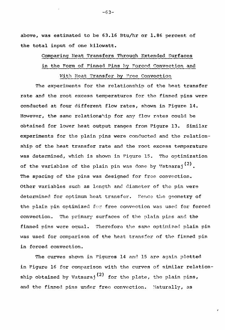
above, was estimated to be 63.16 Btu/hr or 1.86 percent of
the total input of one kilowatt.
q?mparing H,e!!,.t Transfers Th,rouSIh Extended Surfaces
in the Form of Finned Pins by Forced Convect~nd
With I~at Transfer hX ?ree Convection
The experiments for the relationship of the heat transfer
rate and the root excess temperatures for the finned pins were
conducted at four different flow rates, shown in Figure 14.
H~N'ever, the same relationship for any flovf rates could be
obtained for lO\ler heat output ranges from Figure 13. Similar
experiments for the plain pins were conducted and the relation-
ship of the heat transfer rate and the root excess temperature
was determined, which is shown in Figure 15. The optimization
f th . ab 1 f th 1· i d b'l t· · ( 2 ) o e var1 as 0 . e p a1n p n was .one Y·8 sara] •
The spacing of the pins was designed for free convection.
Other variables such as length and. diameter of the pin 'Y,ere
determined for optimum heat transfer. Hence the geometry of
the plain pin optimized for free convection was used for forced
convection. The primary surfaces of the plain pins and the
finned pins were equal. Therefore the same optimIzed plain pin
was used for comparison of the heat trans=er of the finned pin
in forced convection.
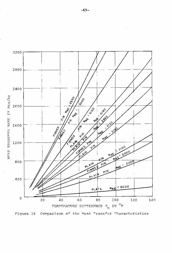
The curves sh~~n in Figures 14 and 15 are again plotted
in Figure 16 for comparison with the curves of similar relation
ship obtained by vatsaraj(2) for the plate, the plain pins,
and the finned pins under free convection. Naturally, as

~ .c ""'-~ +J cc z H
~ 8
~ ~ M ~ tI)
z tZ 8
8 ~ ~ tI:
~-64-
3200
2800 Notations:
• NRe
== 6190.0 I
,- I 2400 I( NRe 5340.0 =
Ii' r-------t-------------1-----I ' I I : I
" NRe 3780.0 = : I
I
2000 e N = 2160.0 Re
1600 ---+-------
1200 -~-----.-~--••• -.-••• ~-~--j I
800 I :
----- ~------- -- ----- - --~------ I ----------t---- ----------I
I
400
o
Figure 15
I , i I
-----,------t-----f------t
_~~ __ 1 20 40 60 80 100
TEMPERATURE DIFFERENCE e IN OF o
120 140
Graph Showing 9 vs. Heat Transfer Rate of the Plain Pin at ConstantOReynolds Number
H ..c: "'" ::s ..j.J
a:: !Z H
ILi E-: ".;t IX fX ~~ t:I u.: Z r::::: p::; E-;
E-i ,:[ .. ~ ::r;
-65-
3200------~------~------II------TT~r---r_--_r~------,
2800~~---~·------~------~+-·---+_~-----·--·~------~--r_~
2400
2000
1600
1200
800
400
o 20 40 60 80 100
TEMPEPATURE DI:PFERFNCE 0 IN OF o
120
Figure 16 Co~parison of the Feat Transfer r.haracteristics
140

6-
expected the heat transfer rate by forced convection was much
higher than that obtained by free convection for all root
excess temperatures. The higher the Reynolds numbers the
higher is the increase in heat transfer rate per unit temp-
erature difference. The heat transfer rate for very high
root excess temperatures under forced convection could not be
obtained because the heat box was not designed for high heat
input.
Sa.'nple Calculations for the ~eynolds N~be~
and the Film Coefficient
For calculating the Reynolds number and the film coefficient,
equations given in the section on Characteristi~ Len9t~ and
Reynolds Number for :the FI'p~ ~cross. t~ Finn~d Pin ~anks are
used. In equation (3-6-1), the product of the velocity and
the density is replaced by the }mSS VELOCITY G , which is max
based on the minimum area.
Finned Pin Assembl~ The measured dimensions for the
finned pin banks are as follows:
SL == 3/8 inch
ST == 1-1/2 inches
The center-to-center distance between the pins in
adjacent tra.nsverse rows is SL' I which is related to a,no
ST by:
(7-
or:
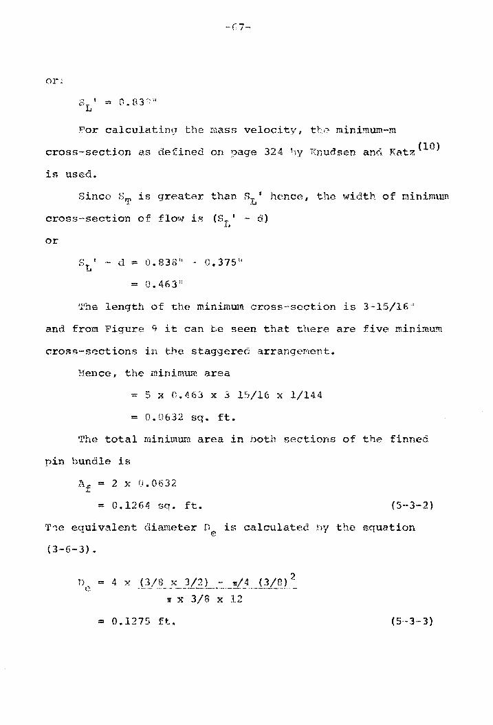
For calculatinq the rilaSS velocity I tr:,.,? rninimum-m
t . d f' ':J 32 A} ... ,.. d :"I Tr t ( 10) cross-sec 1.on as e. ·~nea on page . ~~iy I:"nusen ann .Da z
is used.
Since ST is greater than SL J h('~nce, the width of minimum
cross-section of £10'11 is (SIt'- d)
or
- d := U.83S ti "- 0.375
Ifhe length of minimum cross~section is 3, ... 15/16
and from Figure 9 it can seen that there are five minimum
cross-sections in arrangement.
Hence, the minimum area
- 5 x 0.4 x 3 15/16 x 1/144
= 0.0632 • ft.
'fhe total minimura area in hoth sections of the finned
pin bundle is
Af = 2 x 0.0632
= O. 12 64 sq. ft. (S-3-2)
T lle equivalent diameter is calculated 'ny the equation
(3-6-3).
'If x 3/8 x 12
= 0.1275 ft. ( 3-3)

~-6B-
The readinq of the micromanometer in inches of water
= o. 2392'~
The pressure differential at the nozzle due to
the air flow is
= (0.2392 12) x 62.2
= 1.24 Ib/sq. ft.
The following properties of air are noted at BOoF:
p = 0.07394 lh/eu/ ft
k = 0.01499 Btu/ft hr of
-5 ~ = 1.2497 x 10 1h/ft/sec
The quantity of flow through 3 nozzle is given by
11'
q == if x (d)2
= 1.61 cu. ft./sec.
The area of cross-section of the nozzle
i x (3/12)2
11' 64 sq. ft.
hence, t,he veloci ty of air through the nozzJ e
= 6-i f 1.610
= 32.75 ft/sec
The Reynolds numh~r of air at the throat of the nozzle

== 48700
The coefficient of discharge of a.ir a.t a ~eynolds number
of 48700 is found from P.eference (4) as 0 .. 99 ..
Hence, the flo,'" rate becomes
q == 1.610 x 0.99
== 1.592 cu. ft./sec_
The mean velocity of flow in the w.ind tunnel across
the finned pin
u == 1.592 ~ 0.1264 m
== 12.6 it/sec
Hence, the mass velocity
G == 12.6 x 0.7394 max
The Reynolds number is then given by
N == R.e 12.6 x 0.07394 x 0.1275
- . ~w5 1 .. 2497 x 10
c 9550
and. the Nusselt's number is calculated as
NNU = 0.12 x (9550)°·684
== 64.8
Therefore, the film coefficient is
h == 64.B x 0.01499
0.12'5"
(5-3-4)
(5-3--5 )
(5-3-6)

-70-
Plain Pin Assembly. The measured distances for the plain
pin banks are as follows:
SL == 3/8"
ST = 3/4"
S • == 0.531" L
Since ST is greater than SL' the width of minimum cross
section of flow is (SL' - d).
or
SL' - d = 0.531" - 0.1875"
= 0.3435"
The length of the minirou1"'1 cross-section is 3-15/16 It I
and there are 11 minimum cross-sections in the staggered form.
Hence, the minimum area
== 11 x 0.3435 x 3 15/15 x 1/144
= 0.103 sq. ft.
The total minimum area in both sections of the plain
pin bundle
== 2 x 0.103
== 0.206 sq. ft.
The equivalent diameter De' is
==
3 3 11' 3 2 8" x '4 - 4 (IT)
3 x 1"6 x 12
== 0.1434 ft.
The reading of the micromanometer in inches of water

-71-
:: 0.2215"
Hence, the pressure differential D at the nozzle due p
to the air flow is
= (0.2215 f 12) x 62.2
= 1.148 Ib/sq. ft.
The following properties of air are noted at 89.30F:
p = 0.0726 Ib/eu.ft.
k = 0.0152 Btu/ft. hr. OF
1.266 x 10⁻⁵ 1b/ft. sec.
The quantity of air through the 3 11 nozzle is given by
w 2 I q = 4 x (0.25) x
2x32.l1xl.148 - 0.0726
= 1.562 cu. ft./sec.
1f Since the area of cross-section of the nozzle 64 sq. ft.,
the velocity of the air flow through the nozzle is
" = 1.562 f 64
= 31.8 ft/sec
The Reynolds number of air through the nozzle
31.8 x 0.0726 x 3 = 1.266 x 10-5 x 12
=: 45600
The coefficient of discharge for this flow rate is found
as 0.99
Hence, the quantity of the air flow is
-72-
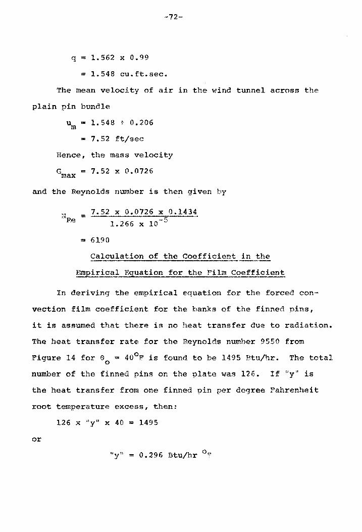
q = 1.562 x 0.99
== 1.548 cu.ft.sec.
The mean velocity of air in the wind tunnel across the
plain pin bundle
urn = 1.548 f 0.206
== 7.52 ft/sec
Hence, the mass velocity
Gmax = 7.52 x 0.0726
and the Reynolds number is then given by
N == 7.52 x 0.0726 x 0.1434 ~ Re 1. 266 x 10 - 5
== 6190
Calculation of the Coefficient in the
Emeirical Eguation for the Film Coefficient
In deriving the empirical equation for the forced con-
vection film coefficient for the banks of the finned pins,
it is assumed that there is no heat transfer due to radiation.
The heat transfer rate for the Reynolds number 9550 from
Figure 14 for 90
= 40°F is found to be 1495 Btu/hr. The total
number of the finned pins on the plate was 126. If ~Iy!t is
the heat transfer from one finned pin per degree Fahrenheit
root temperature excess, then:
126 x nyu x 40 = 1495
or

-73-
Hence, for 100°F root excess temperature, the heat transfer
rate is 29.6 Btu/hr. From Figure 2, the value of the film
coefficient corresponding to the heat transfer rate of 29.6
2 0 Btu/hr was found to be 4.39 Btu/ft hr F. But from equation
(5-3-6) the value of h is 7.6 BtU/ft2 hr of. Therefore, the
value of Kl used in the equation (3-5-12) is:
Kl = 4.39/7.6
= 0.58
Figure 17 shows two curves of Reynolds numbers versus
the Nusselt numbers - one using the value of Kl in the
equation (3-S-12) as unity, and the other as 0.58.
Effectiveness
The effectiveness of the forced convection heat transfer
for the finned pins would be different for different Reynolds
numbers. The effectiveness can again be defined in two ways,
i.e., Cal with respect to the finned pin assembly for free
convection and (b) with respect to the primary surface for
free convection.
If Qn is the heat transfer for the finned pin assembly at ~
any Reynolds numbers, Of is the heat transfer of the
finned pin assembly for free convection, and Qp is the heat
transfer of the primary surface, i.e., of the plate for
free convection, then the percentage effectiveness e,
Q - Qf R 100 aa = x Qf
(5-5-1)
Q - Q R _E x 100 eb = Qp (5-5-2)

"'" <Ll
J
80
60
+J 40 .-t
<Ll 00 Ul ::s z
20
o
Notations
k = 1.0
------ k = 0.58
---1 --
2000 4000 6000 8000 10000
R.EYNOLDS NUMBER
Figure 17 Reynolds Number versus Nusselt Number of the Finned Pin Banks.
12000
I ......,J ~ I

The graph of the effectiveness for different neynolds
numbers is shown in Figure 18 where the eff~ctiveness is
plotted against the excess root temperature.

3200
2800
2400
(/)
til rx:I 2000 z ~ H ~ CJ til ~ 1600 ~ fii
E-t Z fii CJ
1200 p:; ~ p.,
800
400
o
-----~~ Notations: I - -- -_ -I_c_ -- .... ... .... ..... e - ..... a I - .... ... --
I - ----- e b -..... I ... ! ... ... i .....
I I A: NRe = 4120.0 ! I
I ! B: NRe = 6150.0 I
I I c: N
Re = 8660.0 !
I : B D: NRe = 9550.0 i -r--------t _ - --1=-- r - 1 --i-- --I ! I I.
I
i
I i I I
I
I
i I
I
-20
! i
-- - - -! --I -. I
i
I I -~------4
I
! I
i I I
\ I I I
I J--r---J A - =
I ----~----'- --I - - --!
I I I I
I I +------I
I
I i I I I I I
I I I
D I
i c --B
I A
i ; 1
40 60 80 100
ROOT EXCESS TEMPERATURE e IN OF o
I
I
120
Figure 18 Effectiveness of the Finned Pin
140

-77-
VI. CONCLUSION
It is seen that under similar flow conditions, the
finned pin behaves better than the plain pin. As far as
the heat removal capability with respect to the prima~J
surface is concerned, at an average flow rate as used in
the experiment, the finned pin is about 28 times more
effective.

VI I • SU~1Jvl11 .. RY
It has been shown that by increasing the film coefficient
"h" by means of forced convection the heat transfer rate of a
finned pin can be considerably improved. For an average flow
rate of air over the extended surfaces, throughout the invest
igation the increase in the effectiveness was as much as 4.60
times over the free convection process. However the effect
iveness decreases with the increasing root excess temperatures.
The heat loss through the insulation was about 1.86
percent, whlch will not impair the accuracy for engineering
applications.

-79-
VIII. ACKNO~1LEDG~.ENTS
The author sincerely tt1ishes to thank Professor S.T" Hsu
for accepting the position as chairman the author's
graduate committee, for suggesting this topic for his thesis,
and for helping him on many problems. 'I'he author also wishes
to acknowledge the invaluable assistance from Professors
J.!\. Jones, B.L. Wood, R.A. Comparin, C.H. l!ong, and o. Stra'tvn
of the M.echanical Engineering Department. Special appreciation
is offered to Professors B.T. Hurst and E.S. Bell of the
Agricultural Engineering Deoartment for makinq ava.ilahle
some of their instruments to the author.
It was because of the special efforts of Mr. J. Nash
and other staff members of the Computing Center of VPI that
the program of optimization was successfully carried out
and thanks are offered to them also.
Finally the author wishes to acknowledge thanks to
~'liss "JoAnn Humphrey and Mrs. R. W. Thompson for typing.

-60-
IX. BIBLIOGRl1.PHY
1. Hsieh, IJ .. C., H Heat Transfer from a Finned Pin to the lAJnbient Air!;, Thesis in Mechanical I~ngineering, Virginia Polytechnic Institut~ (1963).
2.. Va.tsaraj, B .. C .. , "Optimization of the Design of an Extended Surface with Finned Pins , Thesis in Mechanical Rngineering, \lirginia Polytechnic Institute (1964).
3. Hsu, S.T., "rnqineering Heat Transfer i, D. Van Nostrand
Co. Inc., Princeton, N.J. (1963).
4. Supplement to PuS.M.E. Power TeBt Codes, Chapter 4, Plow !.'leasurement Part 5, Heasurement of Quantity of Materials PTC 19.51 4-1959.
5. Kline, S.J. i Abbott, D.E!. ~ Fox, P.W., nOot.imum Design of Stra.ight-ltfalled ffusers", Paper No .. 5B'''1\-137, A.S.M.F. Transactions, Journal of Basic Engineering. V 81, Sar. D n3, .. 1950, page 321.
6. ~vard, D. J.. and. Young, E .. H. , Ecat iJ.:iranr:> fer and Pressure Drop of Air in Forced Convection Across Triangular Pi tcl'i BanJ:.:s of Finnoc. Tubes L I Chenical Lngineering Progress Symposium, Series no .. 29, 1959, Vol .. 55, page 37.
7. Schneider I P .. S .. I ;'Conduction Heai: ;rransfer l', Second
Printing, A,daisan·-Wesley Publishin,j Co., Inc. (1957).
B .. Kays, ~v .. ~1. and London, p,. L., H Compact Rea t Exchangers H ,
r-lcGraw·-Eill Book .. Co. T Inc. (1958) ..
9. r~c,l~.dams , ...., ~j Heat Transmission", 'l'hird Edi.tion, McGraw Hill Boo}( Co. I Inc. (19 )"
10. Knudsen, J.G .. and Katz, D.1,., Flu.id nynamics and Heat Transfer" I McGra\'1-Hi11 Book Co., Inc. (1958).
11. Jakob, M., 'lieat 'J.1ransfer I Vol. 1, J'ohn Hiley and Sons, Inc., New York, (1949).
12. Harper, W.B. and Brown, D .. R., "r,fathematical Equations for Heat Conduction in the Fins of Air Cooled Engines ll
,
NACA Report 158 (1922).
13. Krieth, F., "Principles of Heat Transfer", International Text Book Co., (1960).

-81-
14. Keller, H.H. and Somers, E.V., UHeat Transfer From An Annular Fin of Constant Thickness u
, A.S.M.E. Transactions, Journal of Heat Transfer, May 1959, page 151.
15. Avrami, !'~1. and Little, J.B., uDiffusion of Heat Through a Rectangular Bar and the Cooling and Insulating Effects of Fins u, Journal of l\pplied Physics, vol. 13, 1942, page 255.
16. Starner, K.E. and Mcl4anus, H.M., I·An Experimental Investigation of Free-Convection Heat Transfer From Rectangular Fin Arrays'~, A.S.M.E. Transactions, Journal of Heat Transfer, Aug. 1963, page 273.
17. Deissler, R.G. and Loeffler, A.L., 'tHeat Transfer and Friction for Fluid Flowing Over Surfaces at High Temperatures and High Velocities H
, A.S.M.E. Transactions, Journal of Heat Transfer, Feb. 1959, page 89.
18. Gardner, K.A. and Carnavos, T.C., HThermal· .. Contact. Resistance in Finned Tubes", A.S.M.E. Transact.ions, Journal of Heat Transfer, Nov. 1960, page 279.
19. Hilding, W.E. and Coogan, C.R., HHeat Transfer and Pressure Loss in Internally Finned Tubes fi
, Symposium on Air Cooled Heat Exchangers, A.S.M.E., August 1964, page 57.
20. Theoclitus, G. , and Eckrich, T.L., nAn Experimental Technique for Determining the Effectiveness of Extended Surfaces lf
, Symposium on Air Cooled Heat Exchangers, A.S.M.E., August 1964, page 21.
21. Appl, F.e. and Hung, H.M., "Finned Surfaces With Optimum Fins of Restricted Length U
, Symposium on Air Cooled Heat. Exchangers, A.S.M.E., August 1964, page 37.
22. Hsu, S.T., Hsieh, J.C., and Vatsaraj, B.C., A.S.M.E. Paper 65 - HT - 55, Eighth National Heat Transfer Conference, Los Angeles, August 8 - 11, 1965

x. VITA
The author was born on August 1, 1938, in Sagar,
India. After graduating from high school in 1953, he
attended the Government College in Rewa, India. Then,
joining Jabalpur University in the College of Engineerin.g,
he earned a B. S. degree in mechanical engtneering ,,,1 th
honors in June 1961. Before coming to the United States
he worked for two years with the State !!lectricity
Board as Assistant Engineer, managing a diesel and
thermal power plant. In January 64 he entered Virginia
Polytechnic lnstl tute., Departrnp-nt of ~Ilechan:i.cal Enqineering,
to pursue a graduate program for the degree of rt1aster of
Science in mechanical engineering.. He l~ a member of
the American Society of Mechanical Engineers.

-83-
APPENDIX A
FORTR&~ PROGRru1 FOR COMPUTING THE HEAT T~~SFER RATE
$IBFTC D1 2 READ(S,2000) DL,D,AL,TL,AK,HL
2000 FORMAT (6E13.5) WRITE (6,2000)DL,D,AL,TL,AK,HL DIMENSION H(20) ,B(40) AM=SQRT(4.*HL/(AK*DL» CN=SQRT(2.*HL/(AK*TL» ANRl=CN*DL/2. ANR2=CN*D/2. H (1) =HL /(A.~*AK) M-O. CALL BESSEL(ANRl,M,BJ,BY,BIO,BKO) M=l. CALL BESSEL(ANR1, M,BJ,BY,BIl,BK1) CALL BESSEL(ANR2,M,BJ,BY,BI2,BK2)
2002 FOR.MAT(3E25.10,110 B(1)=3.1415927*CN*AK*TL*DL*(BK1* B12-B11*BK2)
(BKO*B12+B10*BK2) BHI=B(1)/(3.1415927*DL*TL) BMI=SQRT(4.*BHI/(AK*DL» CH=BMI*TL TI=TANH(CH) DO 1 I=1,8 AN=! S=(AL-AN*TL)/(AN+l.) T=TA.~H (AM*S) B(2)={T+H(1»/(1.+T*H(1» H(2*I)=&~/BMI*B(4*I-2) B(4*I)=(TI+H(2*I»/(l.+TI*H(2*I» H(2*I+l)=BMI/AM*B(4*I) B(4*I+2)=(T+H(2*I+l»/(1.T*H(2*I+l» Q=AK*3.1415927/4.*DL**2*&~*100.*B(4*I+2) WRITE(6,?OOl) I,Q
2001 FORMAT(lOOX,12,E15.5) 1 CONTINUB
~O TO ~

APPENDIX B
v s. in No. Volts
1 2 3 4 5 6 7 B 9
10 11 12 13 14 15 16 17 18 19 20 21 22 23 24 25 26
42 42 42 42 42 42 42 55 55 55 55 55 55 68 68 68 68 68 68 79 79 79 79 79 79 79
TAJiI~g I
Measured Heat Transfer Data of the Finned at Constant Heat Supply Ratf!\ Varying1\ir Flow
(Numbering of 14ocations Heferred to ~1urnbers 8, <), 10 & 11)
Heat SUP'91y Dat~ ~irY.l-ow Data --------.- 'Roots of the Fins----~~--'Vlatt me-· Pr. Diff. Room (At the Entrance
A ter read. Q in inches Temp in in Reynolds 1 2
A.mps oF' ~~V OF ~W
2.6 2.6 2.6 2.6 2.6 2.6 2.6 3.5 3.5 3.5 3.5 3.5 3.5 4.3 4.3 4.3 4.3 4.3 4.3 4.9 4.9 4.9 4.9 4.9 4.9 4.9
100.0 100.0 100.0 100.0 100.0 100.0 100.0 200.0 200.0 200.0 200.0 200.0 200.0 300.0 300.0 300.0 300.0 300.0 300.0 395.0 395.0 395.0 395 .. 0 395.0 395.0 395.0
372.5 372.5 372.5 372.5 372.5 372.5 372.5 656.0 656.0 656.0 656.0 656.0 656.0 99B.O 998.0 998.0 998.0
.0 998.0
1320.0 1320.0 1320.0 1320.0 1320.0 1320.0 1320.0
0.3 0.7-0.2395 0.1964 0.1.251 0.0346 0.0000 0 .. 3526
.2395 0.1.964 0.1251 0.0346 O. 0 0.3526 0.2395 0.1964 0.1251 0.0346 0.0000 0.3572 0 .. 2876 0.2395 0.1964 0.1251 0.0346 0.0000
76.0 76.0 77.0 78.0 79.0 79.0 79.0 79.0 79.0 80.0 7q.5 Bl.O 83.0 78.0 79.0 78.0 79.0 80.0 84.0 78 .. 0 7R.O 77.0 78.0 79.0 91.0 85.0
11800 10550
9(}OO 8h60 6920 3610 2000
11500 9560 8610 6910 3575 2000
11490 9550 8660 6920 3575 2000
11570 10580 9600 8660 6920 3575 2000
1.065 1.075 1 .. 120 1.170 1.200 1.330 1.730 1.230 1.270 1.310 1.350 1.590 2.370 1.320 1 .. 380 1.400 1.490 1.790 2.870 1.370 1.420 1.450 1.500 1.590 2.020 2.800
80.3 80.8 82.B RS.O 86.3 91.q
109.1 87.5 89.3 91.0 92.8
103.1 136.0
91.4 94.1 95.0 98.9
111.7 156.4
93.7 95.CJ 97.1 9Q.3
1f'\1."! J~
] '3 ~ ~~
1.065 1.075 1.120 1.170 1.200 1.330 1.730 1.230 1.270 1.310 1.350 1.590 2.380 1.320 1.390 1.410 1.495 1.800 2.880 1.380 1.430 1 .. 460 1.510 l .. rrn 2.n:.;n ?.. /0
80.3 80.8
. 82 .. 8 85.0 86.3
.. ,91 •. 9 109.1
B7.5 89.3 9l.0 92.8
103,.1 136.4 .91.4 :9'4'.5 95.4 ~9.0'
112,;.'1 156,.,9
94 96 .. 97.4 q9.H
103.7 122.6 15 •• 4
I 00 .;:..

TABLE I (Continued)
• __ ., _____ .. _ ...... __ -"-_____ ~. __ " .. ___________ ... ___ ._ .. _., ___ ~_-.~,,,.., __ _.._ .. __ , ___ ~_ .... "'_~_'b_"".....,_~ ,.."' ...... >V>,.''''. __ ... ..- ,_~, .. , ",~_.-'
noots the vins Bntrance of Sa.m. 3 () 4 0 5 0 6 0 7 )3 'No.. MV 'P i',~v p 'l\·~'l P "':-I'f'i.!' F illl'\7 MV ___ ' ___ ",.--....'.,~--__ ---~-~,. .. ----...... -~,,~'-----__ . __ ......,..-...... ,~"" __ ._,_._ ........ _", ___ ._.""'_._, _'""",,,,""_', . .... __ ,· .......................... _._·~_''''"''l_, __ , __ .
1 1.075 80.8 1.075 .8 1.080 81.0 1.090 .3 1.09 al.3 1.095 Bl. 2 1.080 81.0 1.080 81.0 1.100 81.9 1.110 .3 1.11 82.3 1.120 8'.8 3 1.130 83.2 1.130 83.2 1.135 83.5 1.140 83.6 1.15 84.1 1.1 .1 4 1.170 85.0 1.170 95.0 1.180 85.0 1.185 85.2 1.19 85.4 1.20n 86.4 5 1.210 96.7 1.210 86.7 1.230 97.6 1.240 88.0 1.25 8B.4 1.251 98.4 6 1.340 92.3 1.340 92.3 1.370 93.7 1.380 94.1 1.39 4.5 1.3QS 04.7 7 1.750 110.0 1.750 110.0 1.800 111.9 1.820 113.0 1.q3 113.3 1.890 113. 8 1.240 88.0 1.240 88.0 1.270 89.3 1.280 .9 1.33 QO.q 1.30n qO.7 9 1. 0 89.9 1.300 90.9 1.310 91.0 1.320 91.4 1.33 91.9 1.350 q2.R
10 1.320 91.4 1.320 91.4 1.150 92.8 1.~~O 93.5 1.37 q3.7 1.380 q4.1 11 1.350 92.8 1.360 93.5 1.400 .0 1.410 95.4 1.42 95.9 1.430 gn.2 ~ 12 1.600 103.6 1.600 103.6 1.660 105.9 1.680 107.0 1.70 107.9 1.710 InR.2 ~ 13 2.410 137.7 2.420 138.1 2.520 142.1 2.550 143.5 2.57 144.2 '.58~ 144.6 !
14 1.330 91.9 1.350 92.8 1.36093.5 1.380 94.1 1.4" 95.0 1.410 g5.4 ~5 1.390 94.5 1.390 94.5 1.450 97.1 1.460 97.6 1.18 98.4 1.500 16 1.420 95.9 1.430 96.2 1.490 98.8 1.560 99.2 1.49 9B.O 1.570 Q 7 17 1.500 99.R 1.530 100.6 1.570 101.7 1.600 103.7 1.61 104.0 1.670 104.4 18 1.81n 112.4 1. 0 113.0 1.9an 116.5 1.920 117.1 1.Q3 ] .6 1.Q70 119.3 19 2.90n 157.2 2.960 159.0 3.08U 164.q 3.140 167.3 3.14 167.3 3.200 169.7 20 1.380 94.1 1.420 96.9 1.460 97.6 1.480 98.4 1.50 9q.8 1.520 InO.~ 21 1.430 96.2 1.450 97.1 1.490 98.9 1.500 99.2 1. 100.1 1.550 101.4 22 1.470 98.0 1.480 9R.3 1.520 100.1 1.550 101.4 1.56 101.9 1.570 102.~ 23 1.520 100.1 1.540 101.0 1.570 102.3 1.600 103.7 1.61 104.0 1.620 104.4 24 1.610 104.0 1.620 104.1 1.700 107.9 1.730 109.1 1.75 110.0 1.770 110.7 25 2.070 123.5 2.170 127.7 2.240 130.6 2.?60 131.4 2.2B 132.2 7 e 3 133.1 26 3.000 161.7 3.150 167.7 3.160 168.1 3.200 169.3 3.24 1.3 3.300 173~7
_~. _____ ..... __ ~-"" __ ",.._. _____ ,~ __ " ___ ._" __ .. _,,_"" ___ ,_. ........... _.l._ ...... _.,_"""_ .. _., .. _ .... ~ ........ _"' .. ,,~"

TABLE I (Continued)
Roots of the Fins (At the Entrance of Flow) Sam. 9 10 11 12 13 14
No. MV of MV of MV of MV of MV of MV of
1 1.04 79.8 1.04 79.8 1.050 79.6 1.055 79.9 1.055 79.9 1.055 79.9 2 1.07 80.6 1.07 80.6 1.075 80.8 1.080 81.0 1.090 81.4 1.095 81.6 3 1.11 82.3 1.11 82.3 1.120 82.8 1.120 82.8 1.130 83.2 1.135 83.5 4 1.17 85.0 1.17 85.0 1.170 85.0 1.175 85.2 1.180 85.5 1.185 85.6 5 1.21 86.7 1.21 86.7 1.220 87.1 1.220 87.1 1.230 87.6 1.230 87.6 6 1.33 91.9 1.33 91.9 1.335 92.1 1.335 92.1 1.340 92.3 1.345 92.2 7 1.73 109.1 1.73 109.1 1.740 109.5 1.750 110.0 1.750 110.0 1.750 110.0 8 1.20 86.3 1.21 86.7 1.220 89.1 1.220 87.1 1.230 87.6 1.270 89.3 9 1.25 88.4 1.25 88.4 1.260 88.9 1.270 85.3 1.280 89.8 1.300 90.9
10 1.27 89.3 1.28 89.8 1.290 90.2 1.300 90.7 1.310 91.0 1.320 91.4 I
11 1.30 90.9 1.31 91.0 1.320 91.4 1.330 91.9 1.340 92.3 1.350 92.8 00 0"1
12 1.55 101.4 1.56 101.9 1.570 102.3 1.580 102.7 1.590 103.1 1.600 103.4 I
13 2.28 132.2 2.29 132.7 2.300 133.0 2.350 135.2 2.360 135.6 1.450 139.3 14 1.30 90.9 1.31 91.0 1.320 91.4 1.330 91.9 1.350 92.8 1.360 93.5 15 1.35 92.8 1.36 93.5 1.360 93.5 1.370 93.8 1.420 95.8 1.450 97.1 16 1.37 93.8 1.38 94.0 1.390 94.5 1.400 95.0 1.420 95.8 1.460 97.4 17 1.42 95.8 1.44 96.0 1.450 97.1 1.460 97.4 1.490 98.8 1.500 99.2 18 1.69 107.4 1.72 108.7 1.730 105.1 1.750 110.0 1.770 110.9 1.780 111.3 19 2.76 152.0 1.79 153.2 2.800 153.7 2.830 154.4 2.860 136.0 2.890 157.6 20 1.35 92.8 1.36 93.2 1.370 93.7 1.440 95.0 1.410 95.4 1.450 97.1 21 1.40 95.0 1.41 95.4 1.400 95.0 1.400 96.3 1.450 97.0 1.480 98.3 22 1.43 96.2 1.44 96.3 1.450 97.1 1.450 97.1 1.480 98.3 1.520 100.1 23 1.47 98.0 1.48 98.3 1.480 98.3 1.490 98.4 1.520 100.1 1.540 101.0 24 1.45 101.0 1.55 101.4 1.580 101.9 1.580 102.7 1.590 103.1 1.680 107.0 25 1.95 118.4 1.96 118.9 1.970 119.3 2.020 121.4 2.080 123.9 2.100 124.7 26 2.68 148.7 2.72 150.4 2.780 152.8 2.950 159.7 2.980 160.9 3.100 165.7

TABLE I (Continued)
-----""-""_" ___ . _____ ,._.,_., .. _"'_.A"'_"._~ ____ ._,._~_ Roots of the FinD Poots of the Fins Surface Outgoing
c (At the Entrance of Flow) (At the Fxit) the Fin .Air '.Jam. 15 of HV 17 oF' r\~.r 18 of M'U 19 op \~l 20 OF
l.' ",1
1 1 .. 060 80.1 1.07 80.6 1.1R 85.4 1.18 PS .. 4 1.05 79.7 1.090 81.4 2 1.100 81.9 1 .. 11 R2.3 1 .. 20 86 .. 3 1 .. 20 86.3 1 .. 06 80.1 1.100 131.9 3 1.140 83.6 1.15 84.1 1.25 88.4 1.25 88.4 1.10 B1.9 1.140 83.f'; 4 1.186 85.8 1.19 25.9 1.32 91.4 1.30 90.,6 1.1'=l 84.0 1.190 85.9 5 1.240 88.0 1.25 B8.4 1.3q 94 .. 5 1.38 .0 1 .. 19 85.9 1 .. 280 89.8 6 1.350 92.8 1.35 92 .. 8 1.62 106.<l 1.59 103.1 1.3f'1 QO.6 1.470 58.~ 7 1.760 110.3 1.78 111.3 2.20 9.0 2.10 124.7 1.70 107.9 2.030 121.8 8 1.280 89.5 1.30 90.9 1.47 98.0 1.4~ 97.1 1.21 86.7 1.300 QO.6 9 1.310 91.n 1.32 91.4 1.56 101 .. 9 1.53 100.7 1.26 88.9 1.370 93.9
10 1.330 91.9 1.34 • 3 1.62 104.4 1 • 103.1 1 .. 29 90.2 1.420 95.8 11 1.380 94.0 1.40 95.0 1.72 109 .. 6 1.68 107.0 1.33 91 .. 9 1.560 101.9 12 1.610 104.0 1.65 105.7 2.13 126.0 2.08 123.9 1.59 102.3 1.910 116.9 13 2.460 139.7 2.49 141.0 3. 115.7 3 .. 22 170.5 2.32 134.0 2.780 2.B 14 1.380 94.1 1.40 95.0 1. 106.7 1.64 105.3 2.2B 89.8 1.425 96.0
1.480 93.9 1.50 99.3 1.80 112,,1 1.76 110.3 1 .. 35 .8 1.500 99.2 16 1.490 99.8 1.51 9').8 1.82 113.0 1.78 111.2 1.35 92.8 1.550 101.1! 17 1.550 101.4 1.60 103.7 2.01 121.0 1.l)6 lIB.'? 1.45 97 .. 1 1.700 107.9 18 1.800 112.0 1.90 116.3 2 .. 59 145.0 2.51 1.S 1 .. 78 110.3 2.300 133.0 19 3.000 161.7 3 .. 10 165.8 4.29 212.6 4 .. 18 20B.2 2.86 156 .. 0 3.370 176.5 20 1 .. 460 57.6 1.50 99.8 1.83 113 .. 4 1.79 111.7 1.32 91.4 1.520 100 .. 1 21 1.500 99.3 1.53 100.6 1.90 116.5 1.87 115.0 1. 93.5 1.580 102.7 22 1.530 100.6 1.55 101.4 1.96 118.Q 1 .. (}2 117.1 1.37 93.8 1.610 104.0 23 1.590 103.1 1.60 103.7 2.00 120.6 1. 119 .. 7 1 .. 77 110.7 1.770 110.7 24 1.700 107.8 1.72 108.3 2.21 129.3 2.1B 128.0 1.94 118.0 1.950 118.4 25 2.180 128.0 2.20 128.0 3.01 162 .. 1 2.99 161.3 2 .. 54 143 .. ° 2.650 147 .. 6 2·6 3.150 167.7 3.20 169.3 4.30 212.9 4.28 212.5 3.76 191.C} 3.650 187.6
.. _ >~_. ___ _t .......... ~~_. ____ ."" •••• ,; ___ ._~.,_"',_" .. _ ..... _. ___ •• _

TABI,E I (Continued)
-"---"'---"-~'; ._----.............. _----------Outgoing ~nds of the
Sa.m. ~w 21 1.\<'!'1 23 l\,f\1 24
")E:: ~~T 26 No. 0p ~~V of OF 0li' 1'4" tI. •• } OF 0T?
~ ........ --.---- ~--"'-"-- ..... ---,----,,.,---.-... ~
1 1.09 31.4 1.09 81.4 1.090 81.4 1.05 79.7 1.05 79.7 1.060 80.1 2 1.57 102.3 1.10 81.9 1.570 102.3 1.07 80.6 1.07 .6 1.08C' 81.0 3 1.12 83.8 1.14 83.6 1.120 .. a 1 .. 12 82.R 1.12 82.8 1.125 83.0 4 1.17 85.0 1.18 85.4 1.160 94.4 1.15 84.0 1.15 84.0 1.170 85.0 5 1.24 88.0 1.24 88.0 1.220 B7.1 1.19 85.9 1. 85.9 1.210 .7 6 1.40 .0 1.40 95.0 1.370 93 .. 8 1.30 90.6 1.30 90.6 1 .. 350 92.R 7 1.70 107.9 1.74 109.5 1.770 110.7 1.57 102.3 1.58 102.7 1.650 105.7 8 1.28 89.8 1.28 89.8 1.310 91.0 1.21 86.7 1.21 86.7 1.230 87.6 9 1.33 91.9 1.33 91.9 1.370 93.8 1.25 98 .. 4 1 .. 25 88.4 1.280 89.8
10 1.37 93.8 1.37 93.8 1.420 95.8 1.28 89.8 1.28 84.8 1.320 91.5 i
11 1.44 96.6 1.44 96.6 1.450 97.1 1.32 91.4 1.32 91.4 1.370 93.8 co 12 1.73 109.1 1.86 114.6 1.780 111.2 1.54 101.0 1.55 101.4 1.620 104.4 00
~
13 2.55 143.5 2.37 136.0 2.580 144.6 2.07 123.5 2.12 125.5 2.250 131.0 14 1.37 93.8 1.37 93.8 1.425 96.0 1.28 84.8 1.28 89.8 1.320 91.4 15 1.47 98.0 1.47 98.0 1.510 99.9 1 .. 34 92.3 1.35 .8 1.390 94.5 16 1.48 98.4 1.4B 9B.4 1.550 1.4 1.34 92.3 1.35 92.8 1.400 95 .. 0 17 1.64 105.3 1.61 104.0 1.700 101.9 1.44 96.6 1.45 97.1 1.520 100.1 18 2.17 127.6 2.01 121.0 2.140 126.4 1.7:? 108.6 1 .. 75 110.0 1.950 114.2 19 3.20 169.3 3.12 166.5 3.350 175.7 2.78 lS2.B ?92 158.5 2.010 162.1 20 1.45 97.1 1.46 97.4 1. 100.1 1.33 91.9 1.34 92.3 1.380 94.0 21 1.52 100.1 1.52 100.1 1. 0 102.7 1.37 93.8 1.38 94.0 1.430 96.2 22 1.53 100.7 1.53 100.7 1.610 104.0 1.38 94.0 1.39 96.5 1.440 96.6 23 1.68 107.0 1.62 104.4 1.690 107.4 1.43 96.2 1.49 98.4 1.6BO 107.0 24 1.85 114.2 1.80 112.1 1.920 117.1 1 .. 57 102.3 1.63 104.9 I.BI0 112.4 25 2.50 141.4 2.56 143.9 2.750 151.6 2.00 120.6 2.11 125.1 2.330 134.3 26 3.45 179.7 3.27 172.5 3.570 182.1 2.67 148.3 2.B8 156.8 2.885 157.0
M ___ ~ __ '"~ ..... ___ ,_" .. -------
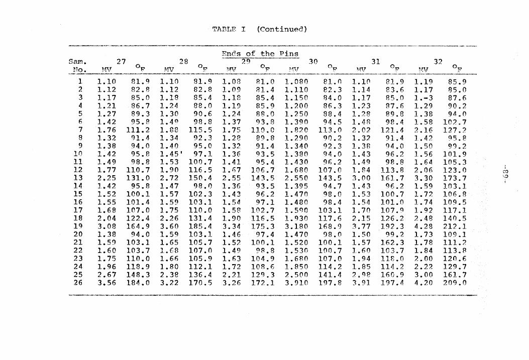
TABI,E I (Continued)
_ ... ..............-_>10 .... _ _ __ "'''' ___ '_'_' __ '' __ " ___ ~'« _~_."'_dO'-"-_""' __ ."""""" _~
Sam. 27 0,.... 28 0
30 31 32 .MV F rf,,, 0-p MV !ft,V of
,-""<-.~"",",~-""-,-,-'----,",,,,,'-----.---
1 1.10 81.q 1.10 81 .. 9 1.08 81.0 1.080 81.0 1.1n 81.9 1.19 85.9 2 1. 82.8 1.12 82.8 1.09 81.4 1.110 82.3 1.14 83.6 1.17 85.0 3 1.17 85.0 1.18 .4 1.18 85.4 1.150 84.0 1.17 85.0 1.-3 87.6 4 1.21 86.7 1.24 88.0 1.19 85.9 1.200 86.3 1.23 R7.6 1. 90.2 5 1.27 89.3 1.30 90.6 1.24 88.0 1.250 88.4 1.28 89.8 1.38 94.0 6 1.42 9S.? 1.49 98.8 1.37 93.8 1.390 94.5 1.48 98.4 1 .. 58 102.7 7 1.76 111.2 1.88 115 .. 5 1.75 110.0 1.820 3.0 2.02 121.4 2 .. 16 127.2 8 1.32 91.4 1.34 92.3 1.23 89.8 1 .. 290 90.2 1.32 91.4 1.42 95.8 9 1.38 94.0 1.40 95.0 1.32 91.4 1.340 92.3 1. 94.0 1.50 .2
10 1.42 95.8 1.45' 97.1 1.36 93.5 1.380 94.0 1.43 96.2 1.56 101.9 11 1..49 98.8 1.53 100.1 1.41 95.4 1.430 96.2 1.49 98.13 1.64 .3 12 1.77 110.7 1.90 116.5 l.n7 106.7 1.6 107.0 1.84 113.8 2.06 123.0 :
~'O
13 2.25 131.0 2.72 150.4 2.55 143.5 2.550 143.5 3.00 161.7 3.30 173.7 ··0
14 1. 95.8 1.47 98.0 1.36 93.5 1. 5 94.7 1.43 .2 1.59 103.1 15 1.52 100.1 1.51 102.3 1.43 96.2 1.470 98.0 1.53 100.7 1.72 106.B 16 1.55 101.4 1.59 3.1 1.54 97.1 1.480 98.4 1.54 101.0 1.74 109.5 17 1.68 107.0 1.75 110.0 1. 102.7 I.S!)!} 103.1 1.70 107.9 1.92 117.1 18 2.04 122.4 2.26 131.4 1.90 116.5 1.930 117.6 2.15 126.2 2.4B 140.5 19 3.08 164.9 3.60 185.4 3.34 175.3 3.180 8.9 3.77 192.3 4.28 212.1 20 1.3B 94.0 1.59 103.1 1.46 97.4 1.470 98.0 1.50 99.2 1.73 109 .. 1 21 1.59 103.1 1.65 105.7 1.52 100.1 1.520 0.1 1. 162.3 1.78 111.2 22 1.60 103.7 1.68 107.0 1.49 ~B.B 1.530 100.7 1.60 103.7 1.84 113.8 23 1.75 110.0 1.66 105.9 1.63 104.9 1.680 107.0 1.94 118.0 2.00 0.6 24 1.96 118.9 1.BO 112.1 1.72 108.6 1.950 114.2 1.85 114.2 2.22 129.7 25 2.67 148.3 2.38 136.4 2.21 129.3 2.500 141.4 :2 .. tH3 160.9 3.00 161.7 26 3. 184.0 3.22 170.5 3.26 172 .. 1 3.9 197.8 3 .. 91 197.4 4.20 209.0
-----------~--------- .... -.. "-,'-.,--------.~---

TABLE I (Con tin ued)
4_-" ___ ~_, __________
Roots Pins
No. MV 33 0T:" MV 34 of 'If1J 35 "1V 315 0T? !"W 37 of MV 38 I __ "" _____ , __ .... ,._·,.. __ .. ~,--~----· _. __
1 1.19 85.9 1.08 81.0 1 .. 13 RS.4 1.19 85.2 1.18 85.4 1.13 83.2 2 1.20 86.3 1.14 83.6 1.1S 85.0 1.20 86.3 1.18 85.4 1.14 83.6 3 1.25 8B.4 1.18 85.0 1.22 87.1 1.25 88.4 1.23 87.6 1.19 85.2 4 1.31 91.0 1.25 88.4 1.29 90.2 1.32 91.5 1.30 90.6 1.25 88.4 5 1.39 94.5 1.30 90.7 1.35 92 .. 8 1.40 95.0 1.36 92.8 1.30 90.7 6 1.60 104.7 1.47 98.0 1.SR 102.7 1. 104.4 1.'57 102.3 1.47 98 .. 0 7 2.18 128.0 2.00 120.6 2.18 128.1 2.20 128.9 2.13 126.0 1.96 118.9 8 1.45 97.1 1.36 93.5 1.58 102.7 1. 98.4 1.46 97.4 1.38 94.0 9 1. 101.0 1.42 95.8 1.56 101.9 1.56 lOl.q 1.54 101.0 1.46 97.4
10 1. 103.1 1.47 98.0 1.62 104.4 1.62 104.4 1.58 102.7 1.50 99.2 11 1.69 107.9 1.53 100.7 1.70 107.9 1.70 107.9 1.67 106.7 1.56 101.9 1
,-0
12 2.09 124.3 1.85 114.2 2.10 124.7 2. 125.5 2.07 123.5 1.87 115.0 0
13 3.23 172.9 2.94 159.3 3.32 174.5 3.34 175.3 3.24 171.3 2.90 157.7 i
14 1.63 104.9 1.50 99.0 1.69 107.4 1.68 107.0 1.66 105.9 1.55 101.4 15 1.76 110.3 1.60 103.7 1 .. 81 112.4 1.80 112.1 1.78 111.2 1.65 106.7 16 1.79 111.7 1.62 104.4 1.84 113.8 1.82 113.0 1.81 112.4 1.67 105.7 17 1.96 118.4 1.76 110.3 2.01 121.0 2.00 120.6 1.98 119.7 1.82 113.0 18 2.51 141.8 2.20 129.0 2.62 146.2 2.57 144.2 2.50 141.4 2.24 130.6 19 4.06 3.6 3.75 191.5 4.30 212.9 4.30 212.9 4.15 207.1 3.65 187.6 20 1.78 111.2 1 .. 62 104.4 1.85 114.2 1.82 113.0 1.82 113.0 1.50 99.2 21 1.88 115.5 1.67 106.7 1.BS 115.5 1.89 5.9 1.90 116.5 1.66 105.9 22 1.92 117.1 1.72 108.6 1.90 116.5 1.95 .4 1.95 119.4 1.70 107.9 23 2.06 123.0 1.78 111.2 2.")7 123.5 1.95 118.4 2.10 124.7 2.03 121.8 24 2.28 132.2 2.05 122.6 2.27 11'.1 2.1t; 6.2 2.25 131.0 2.20 129.0 25 3.11 166.1 2.75 151.6 3.08 164.° 2.91 1 .1 3.20 169.7 3.00 161.7 26 4.27 211.9 4.20 209.0 4.50 220.6 3.q9 200.5 4.50 220.6 4.32 213.7
"~ ,-... ... _____ ~ ___ 4" ___ ,,_ .... , ___ -_ ....... _ ...... ~-'""-....~ ____ ..... _,_

Sam. No.
1 2 3 4 5 6 7 8 9
10 11
13 14 15 16 17 18 19 20 21 22 23 24 25 26
~~, 39 of
1.13 1.16 1.20 1.25 1.30 1. 1.92 1.37 1.42 1.48 1.54 1.87 2.78 1.51 1.62 1.63 1.78 2.23 3.77 1.64 1.69 1.73 1.75 1.90 2.60 3.61
83.2 a4.5
.3 8B.4 90.7 97.4
117.2 93.8 95.8 98.4
101.0 115.0 15'2.8
99.8 104.4 104.9 111.2 130.2 192.7 105.3 107.4 109.1 110.0 116.5 145.5 1B6.0
MV 40 oF'
1.12 1.14 1.18 1.23 1.27 1.44 1.80 1. 1.40 1.53 1.50 1.80 2 .. 52 1.47 1.55 1, .. 56 1.70 2.10 3.56 1.5~ 1.63 1.64 1. 1.96 2.65 3.70
82.8 83.6 85.4 87.6
.3
.6 112.1
92.8 95.0 96.2 99.2
112.1 142.1
98.0 101.4 101.9 107 .. 9 124.7
4.0 102.7 106.9 105.3 112.1 118.9 147.6 189.6
TABLE I (Continued)
.~----.--~-~----.--~~<--.----... --~------- .. -.-----Roots of the Pins
\\", 41 0 ... F 1'1V 42 oF" ~,.,v 43 of MV 44 OF
1 .. 17 1.1R 1.23 1.28 1.36 1.55 1.97 1.45 1.51 1.59 1.65 2.02 2. 1. 1.74 1.75 1.92 2.42 4.03 1.79 1.135 1.88 1.97 2. 2.90 3.92
flS.O 85.4 87.6 a9.8 93 .. 5
IOl.t') 119 .. 3
97.1 99.8
101.9 6.7
121.4 156.8 104.9 109.5 110.0 117.1 13B.1 202 .. 3 111.2
6.2 1 .. 5 119.3 127.2 157.7 198.2
1. 1.20 1.25 1.30 1.37 1.57 2.00 1.45 1.51 1.57 1.65 2.03 2.93 1.61 1.73 1.15 1 .. Q2 8.45 4.07 1.77 1.83 1 .. 87 2.10 2.30 3.20 4.50
85.4 1.13 26 .. 3 l.lf; 88.4 1.20 90.7 1.25 93.8 1.33
102.3 1 .. 120.6 1.
97.1 1.:39 99.8 1.45
102.3 1.50 106.7 1.60 121.8 1.95
8.9 2.76 104.0 1.55 109.1 1.65 110 .. 0 1 .. 68 117.1 1.05 139.3 2. 206.0 3.83 110.7 1.70 113 .. 4 1.76 115.0 1.78 124 .. 7 2.04 133 .. 0 2.25 169.7 3.01 220.6 4.40
83.2 86.5 86.3 B8.4 91.9 99.2
116.9 96.5 97.1 99.2
103.7 118.6 152.0 101.4 105.7 107.0 114.2 134.8 196.4 107.9 110.3 111.2 122.4 131.0 164.5 216.7
1.10 1.13 1.17 1.22 1.27 1.42 1.78 1. 1.37 1.42 1.48 1.77 2.48 1 .. ·~ ~
1.r; II'S 1.69 2.08 3.46 1.57 1.62 1.63 1. 2.07 2.77 3.72
81.9 93.2 8s.n 87.1
.3 95.8
111.2 91.Q 93.A 95.8 98.4
110.7 140.5
(}7.4 100.7 101.4 107.4 123.9 189.1 102.3 104.4 104.9 115.0 123.5 152.4 190.3
--------------... -.----... -----.
t \.~ !-I

TABLE I (Continued)
----.----.. -"-·.-·----·-·-------l-:-'·-------'--·--.- --.- .. -.,.---.-----.~.-.--.-----.,-.. -
1".1 ~verage Pin Temperature
'Root tf'mperature Difference Sample Numl)er 45
---".--~--
1
3 it 5 6 7 8 9
In 11 12 13 14 15 1(; 17 18 19 20 ~1 22 23 24 25
1.12 1.15 1.18 1.24 1.31 1.47 1.87 1.38 1.42 1.46 1.53 1.97 2.69 1.50 1.60 1.62 1.76 2.24 3.87 1.62 1.6?1 1 .. 70 1.78 1.93 2.57 3.92
0Tl' ,1
82 .. 8 84.9 85.4 88 .. 0 91 .. 0 9B .. O
115 .. 0 94.0 95.8 97.4
100.7 115.0 249.1
00 ") , .; • f!.,
103.7 104.4 110 .. 3 130.6 lq6.2 104.4 107.0 107.9 111.2 117.G 144 .. 2 15B.2
t in in * o~_ I 83.7 I 84.72
I,
' 89:6~ , Ql.70
99.67 l1Q .. 57
I 9S.hO I ~7.qO l 99.99 J 103.29 l 11P.09
'I 157.50
102.13
I I 1 I I I I
I 1
106.63 107.50 114.15 13(.3.10 It?7. IfJ7.36 110.16 111 .. f)6 117.00 125.70 157.30 205.7B
o e 0 1?
7.7D 8.72 ('}.17
11.09 12.70 20.67 40.57 16.60 1n.90 20.8('1 23.79 37.09 74.50 24.13 28.63 29.50 35.15 56.10
113.16 29.36 32.16 34.56 39.QO 46.70 76.30
120.78

Sam. No ..
'[IA.BT1F II
APPENDIX B Heasured Heat Transfer Data from pinned ~ .
at Constant Flow Rate and Varyi.ng Heat Inputs
Heat S..!!!?"p1y Data Air Flow Data
Volt me- ?'..rn. me- Y~1att me- Heat Input Pr. Di .. ter read. ter read .. ter read. Q in inches
in in in in of
"Room Reynolds Temp Numbers in OF Volts A..1'!lPS Watts Btu/hr v-Jater ----------, ,- -------.,~-.---.. -.,~,--.--
1 2 3 4 5 6 7 B 9
10 11
13 14 15 16 17 18 19 20 21 22 23 24 25 26 27 28 29
36.5 53.0 69.0 82.0 94.0
102.5 35.0 53.0 68.0 82.0 92.0
102.0 34.0 53.0 68.5 82.0 93.0
102.0 111.0
41.0 57.0 68.1 78.5 88.0 97.0
105.5 118.0 121.5 124.0
2.90 4.00 5.10 5.90 6.30 6.80 2.80 3.45 5.00 5. 6.60 7.30 2.75 4.05 5 .. 00 5.90 6.60 7.25 7.90 2.60 3.50 4.30 4.90 5.50 6.10 6.70 7.40 7.75 8.00
100.0 245.0 400.0 550.0 594.0 696.0 100.0 200.0 400.0 560.0 700.0 840.0 90.0
250.0 400.0 560.0 705.0 855.0
1000.0 100.0 200.0 300 .. r 395.0 500.0 600.0 725.0 875.0 950.0
1000.0
362.0 724.0
1202.0 1652.0 2025.0 2375.0
335.0 695.0
1161.0 166B.O 2075.0 2540.0
319.0 732.0
1170.0 1650.0 2095.0 2520.0 2990.0
364.0 6BO~O
1000.0 1312.0 1668.0 2020.(1 2410.0 2990.0 321n.o 3385.11
0.0438 0.0438 0.0438 0.0438 0.0438 0.0438 0.0973 0.0973 0.0973 0.0973 0.0973 0.0973 0.20 0.2055 0.2055 0.2055 0.2055 0.2055 0.2055 0.2392 0.2392 0.2392 0.2392 0.2392 0.2392 0.2392 0.2392 0.2392 0.2392
90.0 90.0 90.0 90.0
.0 90.0 89.0 89.0 89.0 89.0 89.0 89.0 88.5 88.5 88.5 88.5 BB.S 88.5 88.5 80.0 80 .. 5 21.0 B2.0 R1.0 80.0 80.0 78.0 79.0 80.0
4120.0 4120.0 4120.0 4120.0 4120.0 4120.0 6150.0 6150.0 6150.0 6150.0 6150.0 6150.0 8660.0 8660.0 8660.0 8660.0 8660.0 8660.0 fH;60 .. 0 9550.0 95 .0 9550.0
50.0 9550.0 9550.0 QS50.0 9550.0 QS50.0 9550.0
Data of the l'.,vg. Thermocouples at Hoots of Pins ......-,---_ .. _._-,--~1V
1.87 2.42 3.17 3.70 4.20 4.70 1.85 1.96 2.31 2.75 3.05 3.54 1.47 1.74 2.02 2.30 2.57 2.96 3.29 1.28 1.50 1.71 1. 2.12 2.29 2.55 2.79 2.99 3.13
115.10 138.00
8.70 189.60 209.00 228.20 104.30 118.70 133.50 151.50 163.80 1~3.20
98.10 109.50 121.20 133.20 144.20 160.20 173.40
89.10 99.20
103.10 117.20 125.40 132.70 143.40 153.20 161.50 166.80
Temp D~ff .. ao
J.n OF
25 .. 1 48.0 72.7 99.6
.0 133.2
15.3 ,1 29.7 w 44.5 !
6'.5 74.8 <)4.2 9.6
21.0 32.7
.7 55.7 71.5 84.9 9.7
18.7 27.1 35.2 44.4 :;".7 63.5 75.2 82.5 86.8

Sam. r"'10 ..
1 2 3 4 5 6 7 8 9
10 11 12 13 14 15 16 17 18 19 20 21 22 23 24
B
Volt mc-ter read.
in Volts
34.0 42.5 48.5 59.5 69.5 74.0 36.0 55.0 69.5
.0 88.0 94.0 48.5 59.5 74.0 85.0 98.5
104.0 37.0 47.5 68.0 84.0 97.0
110.0
TABLE III
Hent Trans nata from Plain Pin at Constant. F'lo~'17 Pat.e ant!. Varying Heat Inputs
------------~--.-.--------.-----.-.-----~.-.--.-----.-.,.--------------------.. --.-.~.'"--..-.... -.-~-.. --.•. _._-----_. !!eat SupplX; Dat_~. 7-\ir Data Data of the
]\,to. me- t'Jatt. me-ter read. ter reaG.
in .in liVatts
r'" t"'" t p ff P 1';) Id 1\.vg. Thermo- lremp .:ea .J.npu . r.. . . • "oom "evno. ~S 1 t th D' f..c! 0 (') .. h T . ""T . h coup es a ~ - e 1 - J: .. Q
~, 1.n J.nc, es .emn.'~UP1-'"ers 'l?'t f p. . 0 · f' '00 SO. .. 1ns l.n ~n 0., bn ----·-·o-·--·~· OT.'"
'va ter 'P }'rJ P
2.73 90.0 325.0 0.0277 88.0 2160.0 2.15 127.0 39.0 3.35 135.0 480.5 0.0277 88.0 2160.0 2.59 5.0 57.0 3.70 200.0 611.0 0.0277 .0 2160.0 3.00 157.7 69.7 4.40 300.0 892.0 0.0277 89.0 2160.0 3.60 195.6 q7.6 5.00 395.0 1190.0 0.0277 91.0 2160.0 4.37 215.6 124.6 5.40 455.0 1361.0 0.0277 92.0 2160.0 4.87 235.7 143.7 2.90 100.0 356.0 0.0836 88.0 3780.0 1.B7 115.0 27.0 4.10 250.0 770.0 0.0836 88.0 3780.0 2.57 144.2 56.1 5.05 400.0 1198.0 0.0836 .0 3780.0 3.31 174.1 as.1 5.95 495.0 1678.0 0.0836 90.0 3780.0 4.08 204.4 114.4 6.25 550.0 1895.0 0 .. 0836 90.5 3780.0 4.45 218.5 12R .. O 6.70 612.0 2085.0 0.0936 91.0 3780.0 4.75 230.0 139.0 3.70 200.0 612." 0.1621 99.0 5340.0 2.05 122.6 34.6 4.40 300.0 894.0 0.1621 88.0 5340.0 2.40 137.2 49.2 5.40 455.0 1361.0 0.1621 89.0 5340.0 3.00 161.7 72.7 6.20 605.0 00.0 0.1621 99.0 5340.0 3.55 1B3.6 94.6 6.80 675.0 2284.0 0.1621 89.0 5340.0 4.15 207.1 118.1 7.30 760.0 2584.0 0.1621 90.0 5340.0 4.62 225.0 135.0 2.42 108.0 368.0 0.2215 8B.0 6190.0 1.68 107.0 19.0 3.65 205.0 591.0 0.2215 OB.O 6190.0 2.00 120.6 32.6 5.03 395.0 1167.0 0.2215 88.0 6190.0 2.63 146.7 5P.7 6.15 605.0 1762.0 n.2~15 .0 6190.0 3.32 174.5 B5.5 7.00 800.0 2315.0 0.2215 90.5 6190.0 3.98 200.5 110.0 B.OO 1100.0 3000.0 0.2215 91.0 ~190.0 4.74 229.6 138.6
'.,0 .:::..
-----.----.---.--,-~--,---.. ---. ,----------,_.--.- "-------,.--..• ----~-----~.-------

A.BSTRACT
The original idea of Professor ~su on extended surfaces
with finned pins has been proved by Hsieh ano '\Tatsaraj that
the finned pins can improve the rate of h~at transfer by as
much as 85 percent r,7i th an increase in effect! ven.ess of
61 percent. The objective of conductinq this investigation
was to find the improvement in the rate of heat transfer by
increasing the air-side film coefficient through forced
. convection. In this thesis, the variables of the flnned
pin were optimized for operation under a condition of
forced convectton. l\n experimental investigation \.,as con
ducted to verify the auperiorit.y of the finned pin over
other extended surfaces under forced convect.ion.
1. Theoretical investigation consisted of~
(a) Determination of the relationship betlJleen the
overall heat transfer coefficient and the
individual air-side film copfficient.
(b) Optimization of the variables of the finned
pin, ano
(e) Derivation of the empirical f('~rT';ula -For the film
cOE."fficient in the 1\Tusselt's ~:auati0n forI"'.
2. Experimental investiCfC:ltion comprised of~
Ca) Buildin.g an apparatus to test the heat removal
capability of the extended surfaces at various
Peynolds numbers, and
(h) Testing for comparison of heat flo,,,, rates for
the finned pin and the nlain pin.
3. Conclusions were based on~ Comparisons of the heat
transfer rates of the finned pin and the plain pin
for different flot., rate!=;. ~.t equal flo~l rates, the
finned pin was shown to transfer more heat than the
plain pin. For a reasonahle increase in the film
coefficient under forced convection, the finned pin
was found to improve in effectiveness hy four anc1
one-half times over that when under free convection,
and about 28 times over the primary surface under
free convection.