Embed Size (px)
Citation preview

HEAT LOAD CALCULATION AND ANALYSIS FOR COMMERCIAL
BUILDING AIR CONDITIONING SYSTEM
TAN FOO CHUAN
A project report submitted in partial fulfilment of the
requirements for the award of the degree of
Masters of Science (Mechanical Engineering)
Faculty of Mechanical Engineering
Universiti Teknologi Malaysia
JULY 2017

iii
Parents who raised me up
Brothers and sister who were raised with me
Friends who shared the shoulders with me
Humanity

iv
ACKNOWLEDGEMENT
I would first like to thank my thesis advisor Prof. Dr. Mazlan Abdu l Wahid
of the Faculty of Mechanical Engineering at University Teknologi Malaysia. The
door to Prof. Dr. Mazlan office was always open whenever I ran into a trouble spot
or had a question about my research or writing. He consistently allowed this paper to
be my own work, but steered me in the right the direction whenever he thought I
needed it.
I would also like to thank the experts who were involved in the validation
survey for this research project: Ir.Yuen Cheng Piou and Ar.Lim See Heing. Without
their passionate participation and input into the air conditioning system and building
envelope design and specification, the validation survey could not have been
successfully conducted.
My Hourly Analysis Program (HAP) advisor Mr.Douglas Wong of the
Design and Sale Manager at Carrier Malaysia Sdn Bhd and Second reader Ir.Ng
Yong Kong the Deputy Green Building Index (GBI) Facilitator Course of this thesis
should also be recognized, and I am gratefully indebted to their very valuable
comments on this thesis.
Finally, I must express my very profound gratitude to my parents and to my
best friend for providing me with unfailing support and continuous encouragement
throughout my years of study and through the process of researching and writing this
thesis. This accomplishment would not have been possible without them. Thank you.

v
ABSTRACT
Air conditioning system consume more than 50% of total commercial
building energy consumption such as hotel, office, shopping mall and hospital in
Malaysia. Solar heat through fenestration particularly on vertical surfaces play as
major role in determining the thermal performance of a building. Maximum solar
heat gain factors (SHGFs) has been used to estimate the peak heat load. This project
describes the procedure of peak heat load calculation by using overall thermal
transfer value (OTTV) and hourly analysis program (HAP) to obtain the heat load
profile. A 33 story hotel building layout and envelope is being used and further
optimization on the building envelope configuration has been done to observe the
result. This research have showed how building envelop configuration affect the
building cooling load requirement and apply in decision making base on the return of
investment (ROI). The hourly analysis program result have showed that hotel air
conditioning system operated at 80% or higher cooling capacity (Peak load) only
during 1pm to 3pm and most of the time plant room is operate at Part Load
condition. Plant room energy consumption and return of investment (ROI) analysis
help in decision making on the particular building envelope configuration. The result
showed that ROI period increase with the quantity of double glazed with low-E glass
applied in hotel envelope and it is more cost effective if this type of glass is being
apply at non shaded external surface. This study also carry out ROI evaluation and
comparison for the plant room that with and without variable speed drive (VSD), the
result showed that VSD plant room only take around 2 years to get the return of the
initial investment cost.

vi
ABSTRAK
Di Malaysia, kegunaan tenaga sistem penghawa dingin bangunan komersial
seperti hotel, pejabat, pusat membeli-belah dan hospital adalah lebih daripada 50%
tenaga daripada jumlah kegunaan tenaga seluruh bangunan. Haba solar yang melalui
perbukaan cermin tingkap terutamanya permukaan menegak memainkan peranan
yang penting untuk menentukan prestasi haba sebuah bangunan. Faktor maksimum
peruntukan haba solar telah diguna untuk menganggarkan kuasa haba maksimum
yang diperolehi oleh bangunan. Projek ini menerangkan prosedur penganggaran
peruntukan kuasa haba maksimum sebuah bangunan dengan cara megunakan nilai
keseluruhan pemindahan haba (OTTV) dan jugak megunakan program simulasi yang
mengira peruntukan haba setiap jam (HAP) untuk mendapatkan profil peruntukan
haba bagunan. Pelan sebuah bagunan hotel sedia ada dan sampul bangunan telah di
gunakan dan pengoptimuman terhadap konfigurasi sampul bangunan dijalankan
untuk memerhati pengubahan peruntukan kuasa haba bagunan tersebut. Kajian ini
menunjukan bagaimana konfigurasi sampul bangunan menjejas kuasa penyejukan
yang diperlukan dan jugak keputusan yand dibuat berdarsakan pulangan pelaburan.
Program simulasi yang mengira peruntukan haba setiap jam (HAP) telah
menunjukan bahawa sistem penyaman udara hotel tersebut hanya beada di 80% atau
lebih daripada kapasiti penyejukanya pada jam 1pm hingga 3pm sahaja dan
kebanyakan masa bagunan hanya ada pada keadaan separa daripada kapasiti
penyejukanya. Analisis penggunaan tenaga bilik penyejuk dan pulangan pelaburan
bantu membuat keputusan terhadap konfigurasi sampul bangunan. Keputusan
menunjukan tempoh pulangan pelaburan menigkat dengan kegunaan kuantiti kaca
double glazed dengan low-E di sampul hotel dan ia lebih kos efektif jika digunakan
di permukaan dinding yang tidak berlorek. Kajian ini jugak menjalankan penilaian
dan pernadingan tempoh pulangan pelaburan bagi bilik penyejuk dengan dan tanpa
variable speed drive (VSD), keputusan menunjukkan bilik penyejuk dengan VSD
hanya ambil hampil 2 tahun utuk mendapatkan balik kos pelaburan permulaan.

vii
TABLE OF CONTENTS
CHAPTER TITLE PAGE
DECLARATION
DEDICATION
ACKNOWLEDGEMENTS
ABSTRACT
ABSTRAK
TABLE OF CONTENTS
LIST OF TABLES
LIST OF FIGURES
LIST OF ABBREVIATION
LIST OF SYMBOL
ii
iii
iv
v
vi
vii
x
xii
xv
xvi
1 INTRODUCTION 1
1.1 Project Background 1
1.2 Problem Statement 3
1.3 Objectives 3
1.4 Chapter Organisation 4
2 LITERATURE REVIEW 5
2.1 Heat Transfer Mechanism 5
2.1.1 Conduction
2.1.2 Convection
2.1.3 Radiation
5
6
7
2.2 Heat Load Components in Building Heat Load
Calculation
7

viii
2.3
2.4
2.5
2.2.1 Internal Load
2.2.2 External Load
Basic Concept of Overall Thermal Transfer
Value (OTTV) and Hourly Analysis
Program (HAP)
2.3.1 Overall Thermal Transfer Value
(OTTV)
2.3.2 Hourly Analysis Program (HAP)
Commercial Building Air Conditioning
System
2.4.1 Variable Refrigerant Flow
(VRF/VRV) System
2.4.2 Chilled Water System
2.4.3 Air Distribution System
2.4.4 Applied of Variable Speed Drive
(VSD) in Air Conditioning System
2.4.5 Air Cooled Split Unit
2.4.6 Comparison for Chilled water, VRF
and ACSU system
Building Envelope Configuration and
Design
8
8
9
9
10
11
11
12
13
15
16
17
19
3 METHODOLOGY 23
3.1 Introduction 23
3.2 Concept Applied and Procedure in OTTV
Calculation
23
3.3 Procedure of OTTV Calculation Base on
Building Envelop Analysis
25
3.4 Heat Load Calculation Using Hourly
Analysis Program (HAP)
33
3.5 Changing of Building Envelope
Specification
41
ix
4 RESULTS AND DISCUSSION 43
4.1 OTTV Result and Discussion 43
4.2 HAP Result and Discussion 45
4.3 Plant Room Power Consumption 52
4.4 Discussion on Return of Investment for
VSD Plant Room Proposer
53
4.5 Discussion on Return of Investment for
Various Type of Building Envelop
Proposer
54
5 CONCLUSION 58
5.1 Conclusion 58
REFERENCES 60
APPENDICES

x
LIST OF TABLES
TABLE NO. TITLE PAGE
2.1 OTTV and RTTV in Thailand Building Code 10
2.2 Comparison of Part Load Efficiency for VSD and
NON-VSD Water Cooled Chiller
16
2.3 Cooling Energy Reduction by Applying Five
Improved Envelop Design Measure Compare With
Baseline Building
20
2.4 Comparison of Solar Absorptivity (α) for Various
Type of Finishing Surface and Colour
21
2.5 Comparison of U-Value 𝑼𝒘for Various Type of
Walls Construction Method
21
2.6 Comparison of U-Value of Windows (𝑼𝒇) and
Shading Coefficient (SC) for Various Type of Glass
22
3.1 Summary of Wall Information and Specification for
Hotel Room South-West Wall-1-a in Table Format
29
3.2 Summary of Wall Type for Hotel Room from
South-West View
29
3.3 Summary of Typical Wall Type for Hotel Room
from North-East View
30
3.4 Summary of Total Quantity and Wall Type for
Hotel Floor (Level 10~29)
30
3.5 Calculation of Heat Conducted Through Wall 31
3.6 Calculation of Heat Conducted Through Window 32
3.7 Calculation of Solar Heat Gain though Wall 32
3.8 Change of Building Envelop Configuration 42

xi
4.1 Summary of OTTV Result for All Configurations 44
4.2 HAP Air System Sizing Summary for Level-1 Lift
Lobby
45
4.3 HAP Hourly Zone Load for Level-1 Lift Lobby 46
4.4 HAP Plant Sizing Summary for Configuration-2 49
4.5 HAP Plant Load Profile on July and August for
Configuration-2
50
4.6 Comparison of Total Space Peak Load with Plant
Peak Load for Configuration 1 to 6
52
4.7 Efficiency for Plant Room Equipment With and
Without VSD
52
4.8 Calculation of Yearly Plant Room Power
Consumption with and without VSD for
Configuration-1 (OTTV=111)
53
4.9 Calculation of VSD Plant Room Energy Cost
Saving for 6 Types of Building Envelop
Configuration
54
4.10 Calculation of VSD Plant Room Return of
Investment (ROI) for 6 Types of Building Envelop
Configuration
54
4.11 Calculation of additional cost for of Building
Envelop Configuration 1, 2 and 3
55
4.12 Calculation of additional cost for of Building
Envelop Configuration 4, 5 and 6
56
4.13 Calculation of Return of Investment (ROI) for 6
Types of Building Envelop Configuration
57

xii
LIST OF FIGURES
FIGURE NO. TITLE PAGE
2.1
2.2
2.3
2.4
2.5
2.6
2.7
2.8
Heat Transfer in Conduction Mode
Heat Transfer in Convection Mode
Heat Transfer in Radiation Mode
Typical VRF System Schematic Diagram
Typical Chilled Water System Schematic Diagram
Typical Variable Air volume Box (VAV Box)
Control Schematic Diagram
Typical Ducting Layout for Air Distribution
System With Variable Air volume Box (VAV
Box)
Typical Outlook of Wall Mounted Type Air
Cooled Split Unit
6
6
7
12
13
14
14
17
3.1
3.2
3.3
3.4
3.5
3.6
3.7
Top View of The Entire Building Project
Development (“The Shore”)
Hotel North-West Elevation (External wall)
Hotel North-East Elevation (External wall)
Typical Floor Plan for Hotel Room Level 10 and
11
Section View B-B Show in The Figure 3.4 for
Hotel Room
Create Wall Properties for Reinforce Concreate
Wall With White Surface
Create Wall Properties for Brick Wall With ACP
Cladding
25
26
27
28
28
34
34

xiii
3.8
3.9
3.10
3.11
3.12
3.13
3.14
3.15
3.16
3.17
3.18
3.19
3.20
3.21
Create Wall Properties for Brick Wall With
Insulated ACP Cladding
Create Window Properties for Double Glazed
Clear With Low-E and Air Gap Window
Create Window Properties for Using Single
Glazed With Dark Grey Tinted Glass Window
Define Shading Geometry Properties for Hotel
Room
Create Roof Properties for Insulated Steel Deck
Roof
Create Roof Properties for Reinforce Concreate
Roof
Create People Density Profile for Banquet Hall
and Sky Bar
Create Lighting and Machines Load Profile for
Office Area and Hotel Room
Define Space General Information for Sky Bar
Define Space Internal Load Information for Sky
Bar
Define Space External Wall, Window and Door
Information for Sky Bar
Define Space Roof for Sky Bar
Define Space Floor Properties for Sky Bar
Define Space Partition Properties for Sky Bar
34
35
35
36
36
36
37
37
38
38
39
39
40
41
4.1
4.2
4.3
4.4
The Plot of HAP Hourly Zone Load Profile for
Level-1 Lift Lobby
The Plot of HAP Hourly Zone Load Profile for
Level-3A Banquet Hall
The Plot of HAP Hourly Zone Load Profile for
Level-3A Coffee House
The Plot of HAP Hourly Zone Load Profile for
Level-4 Office Area
46
47
48
48

xiv
4.5
The Plot of HAP Plant Load Profile on July and
August for Configuration-2
51

xv
LIST OF ABBREVIATION
OTTV - Overall Thermal Transfer Value
TD - Difference Between Interior and Exterior (K)
TDeq - Equivalent Temperature Difference (K)
WWR - Window-to-Wall Ratio
SF - Solar Factor of Fenestration
SC - Shading Coefficient of Fenestration (Dimensionless)
Uw - U-Value of Opaque Wall (W/m2.K)
Uf - U-Value of Fenestration (W/m2.K)
COP - Coefficient of Performance
RPM - Revolution Per Minuets
𝐹𝐴𝑁𝐸𝐹𝐹 - Fan efficiency
𝑃𝑈𝑀𝑃𝐸𝐹𝐹 - Pump efficiency
SHGFs - - Solar Heat Gain Factors
ROI - Return of Investment
HAP - Hourly Analysis Program
AHU - Air Handling Unit
FCU - Fan Coil Unit
VAV - Variable Air Volume
DX - Direct Expansion
ACMV - Air Conditioning and Mechanical Ventilation
PID - Proportional–Integral–Derivative
BAS - Building Automated System
RT - Refrigerant Tonnage (12,000 btu)

xvi
LIST OF SYMBOLS
Q - Heat flow rate
k - Thermal conductivity of the material
A - Cross-sectional area
dT/dx - Temperature gradient
h - Coefficient of convection
𝑇∞ - Outside temperature
𝑇𝑠 - Surface temperature
T - Absolute temperature of surface
𝜎 - Stefan-Boltzmann constant
α - Solar absorption(dimensionless)
�̇� - Flow rate in CFM (for fan) and usgpm (for pump)
𝜔 - Angular speed (in RPM)
P - Pressure for fan (inch of water gauge) or pump head for pump ( in
feet of water)
R - Thermal resistance (𝐾 𝑊⁄ )

1
CHAPTER 1
INTRODUCTION
1.1 Project Background
Over the past decade, construction industries at tropical countries have given
much more attention on energy saving concepts. To ensure energy savings, the main
key is to reduce air conditioner capacity in a building. This is achievable with a
proper heat load calculation to be carried out to ensure energy saving without
sacrificing the comfort level of the air conditioning system. In a tropical country,
solar heat gain by the building through vertical and horizontal wall created much
more impact than internal load such as heat rejected by human body, machine,
equipment and lighting. The overall thermal transfer value (OTTV) on building
envelopes has become the base reference that determine the building envelopes
thermal performance. Xiaoxia Sang [1] has examined energy-efficient building
envelop design decision making in Hong Kong and found out that there is a large
potential of reducing building cooling energy during building envelop material
selection and design.
In 2005, Lam et al. published a paper in which they described that building
cooling load can be expresses in term of simple two-parameter linear regression
equation involving OTTV and with the further long term data collection such as
ambient temperature, global solar radiation on vertical and horizontal surface, a
simulation technique can be carry out to obtain not only the maximum load but also
the load profile of the building [2].
2
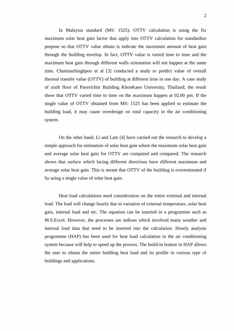
In Malaysia standard (MS: 1525), OTTV calculation is using the fix
maximum solar heat gain factor that apply into OTTV calculation for standardize
purpose so that OTTV value obtain is indicate the maximum amount of heat gain
through the building envelop. In fact, OTTV value is varied time to time and the
maximum heat gain through different walls orientation will not happen at the same
time. ChutinanSinghpoo et al [3] conducted a study to predict value of overall
thermal transfer value (OTTV) of building at different time in one day. A case study
of sixth floor of Pienvichitr Building KhonKaen University, Thailand; the result
show that OTTV varied time to time on the maximum happen at 02.00 pm. If the
single value of OTTV obtained from MS: 1525 has been applied to estimate the
building load, it may cause overdesign on total capacity in the air conditioning
system.
On the other hand, Li and Lam [4] have carried out the research to develop a
simple approach for estimation of solar heat gain where the maximum solar heat gain
and average solar heat gain for OTTV are computed and compared. The research
shows that surface which facing different directions have different maximum and
average solar heat gain. This is meant that OTTV of the building is overestimated if
by using a single value of solar heat gain.
Heat load calculations need consideration on the entire external and internal
load. The load will change hourly due to variation of external temperature, solar heat
gain, internal load and etc. The equation can be inserted in a programme such as
M.S.Excel. However, the processes are tedious which involved many weather and
internal load data that need to be inserted into the calculation. Hourly analysis
programme (HAP) has been used for heat load calculation in the air conditioning
system because will help to speed up the process. The build-in feature in HAP allows
the user to obtain the entire building heat load and its profile in various type of
buildings and applications.

3
1.2 Problem Statement
There are a lot of commercial building in Malaysia do not carry out a
proper building heat load calculation. Most of the air conditioning system
design capacity is only base on rules of thumbs (watt of cooling power
require per unit area). Without a proper heat load calculation to determine the
building envelope thermal performance and heat load profile, designer do not
have enough information for decision making during the building design
stage as a result mechanical and electrical consultant overdesign on the
building system. Moreover, architect do not allocated enough design effort on
the building envelop thermal performance. As a result, the construction and
operation cost increase. Overall thermal transfer value (OTTV) calculation
need to be done during building envelope design and materials selection.
Such information need to be considered while designing the air conditioning
system. In order to obtained heat load profile, energy consumption and cost
analysis has to be carried out properly to achieved final decision.
1.3 Objective
The objectives of this study are as follows:
1. To obtain overall thermal transfer value (OTTV) for a commercial
building with various sets of building envelop configuration and design.
2. To obtain building heat load profile and peak load of building space and
plant room for a commercial building with various sets of building
envelop configuration using hourly analysis programme (HAP).
3. To calculate and compare the energy consumption and return of
investment (ROI) for various sets of building envelop configuration and
air conditioning system. Heat load profile obtained from HAP is applied.
ROI obtained will help to select most suitable building envelop
configuration and air conditioning system design.

4
1.4 Chapter Organisation
This thesis is divided into 5 chapters. Chapter 1 introduce the
background and objectives of the study. Chapter 2 is about the literature
review on the previous research which related to the project in various areas.
This will help to give a better understanding about project contents before
dealing with the calculation and simulation. Chapter 3 describes the
methodology needed for the project which include; how to extract the
information from the floor plan and others specification. Format of OTTV
calculation and summary of data need to define in to the hourly analysis
programme. Chapter 4 gives the results and discussion of the OTTV, heat
load profile. There are also discussion on difference building envelop
configuration and air conditioning design that suitable base on the energy
consumption and Return of Investment (ROI) obtained. Last but not least,
Chapter 5 is the overall conclusion of the project. Furthermore, there are
recommendations of future works is given as well.

60
REFERENCES
1. Sang, X., Pan, W., &Kumaraswamy, M. M. (2014). Informing Energy-
efficient Building Envelope Design Decisions for Hong Kong. Energy Procedia, 62,
123-131.
2. Li, D. H., & Lam, J. C. (2000). Solar heat gain factors and the implications
to building designs in subtropical regions. Energy and Buildings, 32(1), 47-55.
3. Singhpoo, C., Punnucharoenwong, N., &Benjapiyaporn, C. (2015). Study of
the Effect of Temperature Differences on the Overall Thermal Transfer Value of
buildings. Energy Procedia, 79, 348-353.
4. Lam, J. C., Tsang, C. L., Li, D. H., & Cheung, S. O. (2005). Residential
building envelope heat gain and cooling energy requirements. Energy, 30(7), 933-
951
5. Hui, S. C. M., 1997. Overall theraml transfer value (OTTV): how to improve
its control in Hong Kong, In Proc. of the One-day Symposium on Building, Energy
and Environment, 16 October 1997, Shangrila Hotel, Kowloon, Hong Kong, HKIE
BS Division/CIBSE/ASHRAE/PolyU, pp. 12-1 to 12-11.
6. Rattanongphisat, W., &Rordprapat, W. (2014). Strategy for Energy Efficient
Buildings in Tropical Climate. Energy Procedia, 52, 10-17.
7. Malaysia Standard MS 1525:2007, Code Of Practice On Energy Efficiency
And Use Of Renewable Energy For Non-Residential Buildings (First Revision).
8. Malaysia Green Building Confederation. (2015). Green Building Index
Facilitator Course Book I.
9. Food and Agriculture Organization of the United Nations, www.fao.org

61
10. Mitsubishi Heavy Industries VRF Inverter Multi-System Air Conditioners
Catalogue
11. CARRIER MALAYSIA SDN BHD-Chiller technical data sheet