Embed Size (px)
Citation preview

1 1 /
HCⅡseries
Compact Horizontal Machining Center
HC Ⅱ seriesHC 400 Ⅱ
HC 500 Ⅱ
ver. EN 160502 SU

02 /
Product Overview
Basic Information
Basic Structure
Detailed
Information
Options
Applications
Capacity Diagram
Specifications
Customer Support
Service
HCⅡseriesCompact horizontal machining center HC II series is designed to provide maximum productivity, accuracy, and number of convenient features. The compact design offers flexibility to utilize limited factory space efficiently.
HC Ⅱ
series

03 02 /
Contents
02 Product Overview
Basic Information
04 Basic Structure
Detailed Information
07 Standard / Optional
Specifications
09 Applications
13 Capacity Diagram
15 Machine / NC Unit Specifications
18 Customer Support Service
Enhanced Design
New aesthetics and simplified design eases machine operation.
Increased Productivity
New high speed 12,000rpm spindle, wider selection of tool magazine and automation options further enhances versatility and productivity.
Improved Ergonomics
Newly designed operation panel and built-in pallet setup switch further improves ergonomics of the machine.
04 /
Highly rigid machine structure and compact design to meet all users’ needs.
Basic Structure Robust Machine Structure
Doosan engineers have performed FEM analysis to design the most durable and stable structure. As a result, the machine is capable of extensive heavy cutting process.
Compact Design
The compact design allows users to utilize limited factory space efficiently.
2 Machines Required
Vertical Machining Center HC Ⅱ series
1 Machine Required
2 Operators Required 1 Operator Required
Product Overview
Basic Information
Basic Structure
Detailed
Information
Options
Applications
Capacity Diagram
Specifications
Customer Support
Service
HC Ⅱ
series

05 04 /
Travel Axes
Spindle
All axes utilize highly reliable and durable LM roller guides.
12,000rpm spindle option has been added for optimum productivity in high speed machining application.
High Speed Roller Guides
LM roller guides on all axes increases machine reliability and productivity.
High Speed Spindle
Users can select different types of high performance spindle to meet their machining needs. Standard 8,000rpm spindle can deliver up to 353.4N∧m of torque to perform extreme heavy cutting process, while 12,000rpm spindle option can provide maximum productivity in high speed cutting process.
8000r/min
(12000 r/min )
Max. Spindle Speed
Highly rigid and accurate
LM Roller Guides
HC 400 II HC 500 II
Axes Travel (X / Y / Z) 600 / 560 / 565 mm (23.6 / 22 / 22.2 inch) 850 / 700 / 750 mm (33.4 / 27.5 / 29.5 inch)
Rapid Traverse 40 m/min (1574.8 ipm)
ModelSpeedr/min
PowerkW (Hp)
Torque
N·m (ft-lbs)Type
Standard 8000 18.5 / 11 (24.8 / 14.7) 353.4 (260.6)ISO #40
Option 12000 18.5 / 11 (24.8 / 14.7) 117 (86.3)

06 /
80 tool magazine has been added to offer wider range of ATC magazine options.
More reliable and conveniently designed high speed automatic pallet changer.
Tool Magazine
Automatic Pallet Changer (APC)
Wide range of options to meet more users’ needs
Wide selections of tool magazines are available per user’s preference. These automatic tool magazines are operated by our newest servo motor to minimize tool change time, and the fixed address tool storage system makes it easy for users to select desired tool without confusion.
Automatic Tool Changer (ATC)
Cam-type ATC provides high reliability and durability, and minimizes non-cutting time.
High Speed Automatic Pallet Changer
Standard high speed rotary type APC provide extreme reliability and a large work space allows users to easily setup the pallet.
Tool Storage Capacity
40tools
Tool change time
1.5s
{60 / 80 / 120 / 170 / 262}
Max. Workpiece Size
HC 400 II HC 500 II
Pallet Size400 x 400 mm
(15.7 x 15.7 inch)500 x 500 mm
(19.7 x 19.7 inch )
Max. Workpiece Size
Ø600 x H800 mm(23.6 x 31.5 inch)
Ø800 x H900 mm(31.5 x 35.4 inch)
Max. Load 400 kg
(881 lb )500 kg
(1102.3 lb )
D mm
H m
m
Product Overview
Basic Information
Basic Structure
Detailed
Information
Options
Applications
Capacity Diagram
Specifications
Customer Support
Service
HC Ⅱ
series

07 06 /
NO. Division Option HC 400 Ⅱ HC 500 Ⅱ
1
Tool Magazine
40 tools ● ●
2 60 tools ○ ○
3 80 tools ○ ○
4 120 tools ○ ○
5 170 tools ○ ○
6 262 tools ○ ○
7
Tool Specifications
BT40 ● ●
8 CAT40 ○ ○
9 DIN40 ○ ○
10 HSK A-63 ○ ○
11 Mist Collector Mist Collector ○ ○
12
Spindle
8000 r/min 18.5 / 11 kW (24.8 / 14.7 Hp) ● ●
13 12000 r/min 18.5 / 11 kW (24.8 / 14.7 Hp) ○ ○
14 Spindle air curtain ● ●
15
Hydraulic fixturesHydraulic fixture line
2 X 2 ○ ○
16 4 X 4 ○ ○
17 6 X 6 ○ ○
18 8 X 8 ○ ○
19 Hydraulic fixture unit ○ ○
20 Automatic Workpiece Measurement Device
OMP60_RENISHAW ○ ○
21 RMP60_RENISHAW ○ ○
22
Automatic Tool Measurement Device
BK 9 ○ ○
24 Limit Switch (OMRON) ○ ○
25 TS27R ○ ○
27
Chip Handling SystemChip conveyor
Hinged type ○ ○
28 Scraper type ○ ○
29 Drum type ○ ○
30 Chip bucket ○ ○
31
Coolant
FLOOD ● ●
32 FLUSHING ● ●
33 SHOWER ○ ○
35
TSC
1.5 kW 2.0 MPA (2 Hp 290 psi) ○ ○
36 3.0 kW 2.0 MPA (4 Hp 435.1 psi) ○ ○
37 7.5 kW 2.0 MPA (10 Hp 1015.3 psi) ○ ○
38 Coolant gun ○ ○
39 Oil skimmer ○ ○
40 MQL system ○ ○
41Table
Index table ● ●
42 Rotary Table ○ ○
43Pallet
Tapped pallet ● ●
44 T-Slot pallet ○ ○
45AIR
Pallet air seat ○ ○
46 AIR GUN ○ ○
47 MPG Portable MPG ● ●
Standard / Optional Specifications
Diverse optional features are available to meet specific customer requirements.
Standard Optional X N/A

08 /
Chip Conveyor Chip Disposal System
Diverse Options
Proper chip disposal is very important for improving productivity and environment. Therefore, we recommend better chip management for users to work in a safer working environment.
Measurement Systems
Environment-friendly Devices
Flushing coolant Flood coolant
Coolant spray gun on the spindle head
Auto tool damage detection device Ⅰ(BK 9)
Oil skimmer
Screw conveyorAuto tool damage detection device Ⅱ(OMRON)
Mist Collector
Spindle-through coolant spray device (TSC) Automatic tool measuring device (TS 27R)
Shower coolant Coolant gun
MQL system Misting device
Scraper type
Hinge type
Drum filter type Chip Conveyor
HC Ⅱ
series
Product Overview
Basic Information
Basic Structure
Detailed
Information
Options
Applications
Capacity Diagram
Specifications
Customer Support
Service
09 08 /
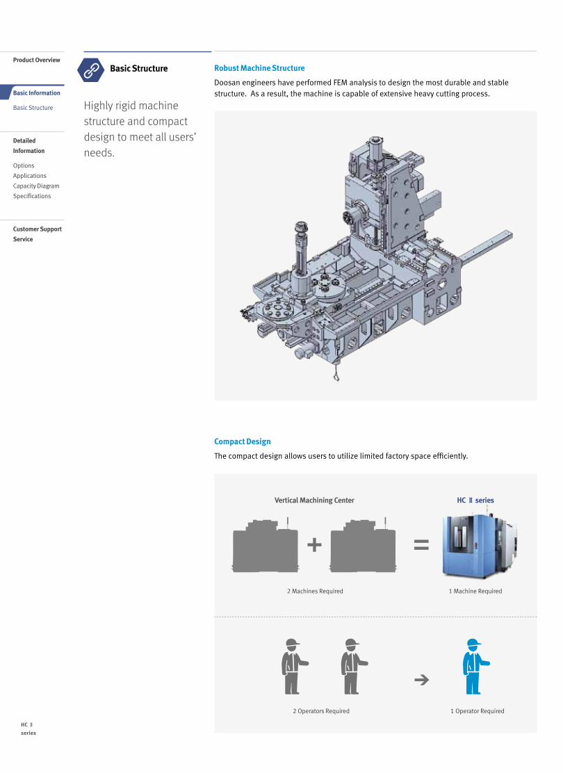
Doosan Pallet Extension System provides automated solution to maximize productivity. Simple installation and ease of maintenance makes it convenient for users to operate and maintain.
Pallet Extension System
Doosan Linear Pallet System [LPS ⅡCompact] The LPS II Compact, a compact & economic pallet extension system, is the most affordable solution that is delivered in full assembly.
Doosan Linear Pallet System [LPS Ⅱ] Doosan’s representative LPS system, designed to provide the optimum automated pallet solution. LPS Ⅱ is capable of multiple extension and layout change to provide flexible manufacturing solution.
LPS 400 II compact LPS 500 II compact
Compatible model HC 400 II HC 500 II
Fork type Single Fork type
No. of machines 1
No. of setup stations 1
No. of pallets 12
Dimensions (L x W) 7190 mm x 2225 mm (283.1 inch x 87.6 inch)
LPS Ⅱcompact
LPS Ⅱ(Linear Pallet System) Major Features
• Expandable System
• Ideal for Managing High Efficiency
Manufacturing Parts
• Stable and efficient operation system
• Faster installation and commissioning
• Compatible with all Doosan Horizontal
Machining Centers
• Easy maintenance
Major Features
• Compact size
• Cost effective installation
• Fully assembled delivery
• Convenient operating system
(DPMS II)
LPS II Model LPS 400 II LPS 500 II
Compatible model HC 400 II HC 500 II
Fork type Twin Fork type
No. of machines 1 – 7
No. of setup stations 1 – 4
No. of pallets 12 ~ 70
Dimensions (L x W) 7824 mm x 2400 mm (308 inch x 94.5 inch)
Built in main controller
LPS Standard Control Software
Doosan Production Management System [DPMS]
• Stores basic data which can be easily put in to provide flexible
production
• Management software for rapid production and changing
production quantity
• LPS management solution for fast and flexible production
The DPMS is a system designed
to ensure effective control and
management of the LPS.
The main window allows
operators to quickly & flexibly
manage the system in case of
sudden change in output.
System Outline
LPS II controller
Machine 1 Machine 2 Machine 3
Profibus-DP
Ethernet
Cable
Cable
Driver
PC
Servo Motor
Stracker Crane
Setup Station 1
Setup Station 2
CC-link
PLC (Mitsubishi)
10 /
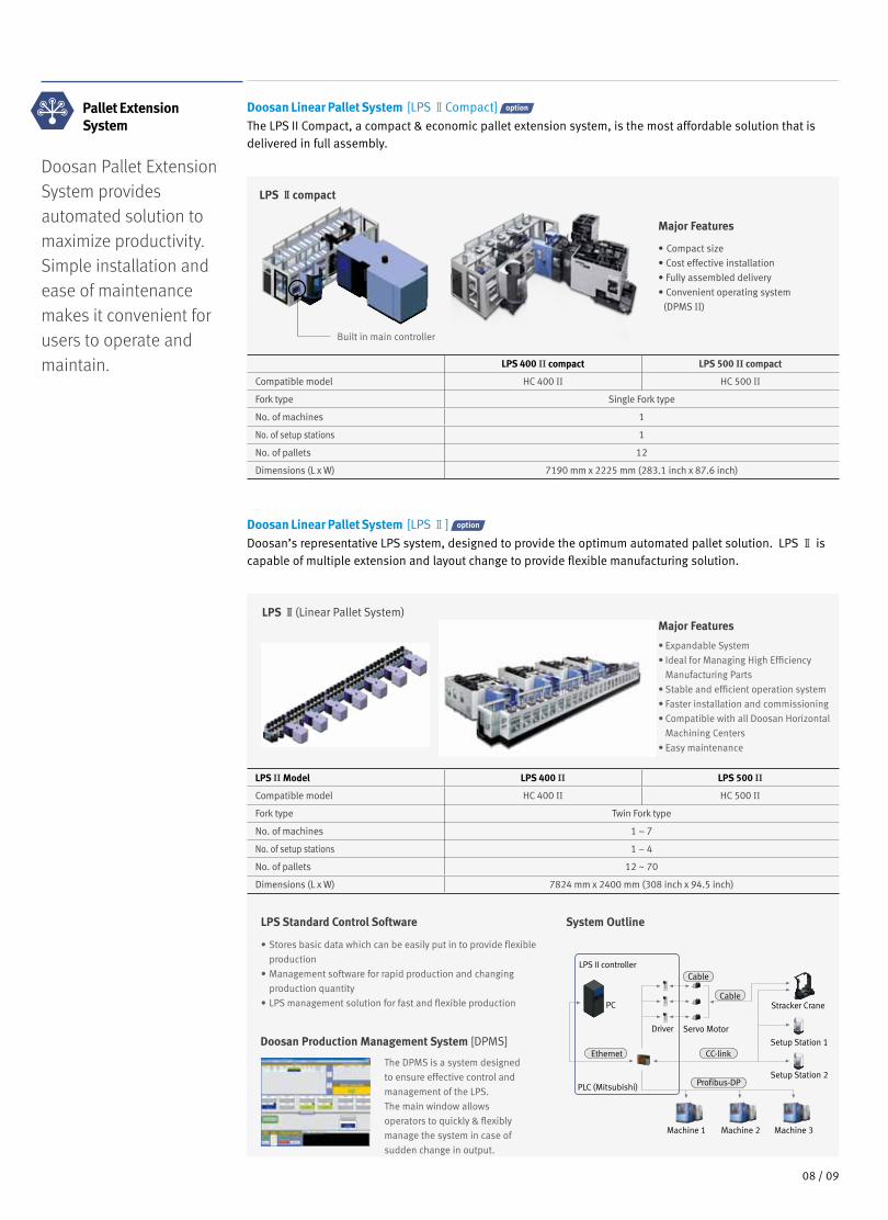
DOOSAN 5 APC
Compact and simple multiple pallet system that allows users to maximize productivity and efficiency.
※ Please consult with Doosan for putting 500 mm pallet on 5 APC.
※ Please consult with Doosan for putting 500 mm pallet on 7 MPS.
Doosan Multiple Pallet System [MPS]
Doosan’s MPS allows users to program and automate up to 7 pallets. This system is ideal for manufacturing variety of parts in small quantity.
7-MPS HC 400 II / HC 500 II
No. of pallets 7
Length required for installation [L] 6918 mm (272.3 inch)
Width required for installation [W] 3684 mm (145 inch)
R364
(14.
3)
R732
(2
8.8)
3684
(145
.0)
6918 (272.4)
* Dimensions does not include chip conveyor and MPS foot board.
Major Features• Compact Footprint
• 3 different setup stations maximize efficiency in setup
• Easy on-site installation
7 MPS
5 APC HC 400 II / HC 500 II
No. of pallets 5
Length required for installation [L] 6274 mm (247 inch)
Width required for installation [W] 3046 mm (120 inch)
HC Ⅱ
series
Product Overview
Basic Information
Basic Structure
Detailed
Information
Options
Applications
Capacity Diagram
Specifications
Customer Support
Service

11 10 /
Convenient Operation Panel
Doosan’s new operation panel design is uniform throughout all new Doosan machines, and it includes number of custom keys which can be utilized by the users to further improve ease of operation.
90°
The operation panel swivels by 90°. Also, displaying various
alarm messages regarding machine or control error further
enhances convenient operation.
The portable MPG provides users
the flexibility to easily see and
setup the workpiece.
Operators can easily upload and
download programs, parameter,
tool data, and ladder program by
PCMCIA card and it also supports DNC
operation.
Special optional buttons can be added to control
fixture clamp/unclamp, counter, timer.
Each buttons are separated by partitions in order
to prevent operation error.
Swivel Type Operation Panel PCMCIA Card
USB PortPortable MPG
Operators can easily upload
and download programs,
parameter, tool data,
and ladder program by
USB drive, however DNC
operation on USB is not
supported.
New operation panel interface allows users to more conveniently operate the machine.
User Friendly

12 /
Tool Support Functions
Operation Support Functions
Operation rate
• Records multiple machine
operation rate
• Support 3 shift operation
• Counts and records 30 day
operation rate
• Display data for specific
period
PMC switch
• Selects function on
the operation panel
• Alternates for toggle
software
• NC option software
Tool load monitor
• Detects tool damage
• Detects abnormalities
during operation
• Detects air cutting
Tool management II
• Manages tool magazine
• Tool life management
• Estimates tool life
• Manages tool status
• Balluff Tool ID function
Tool management I
• Manages tool magazine
• Displays tool status
• Fastems tool add /
remove function
Help Text Function
M Code List
• Displays list of major
M codes
Easy NC parameter
• Displays detail
descriptions for major
parameters
• Displays parameter
settings
Calculator
• Calculator function
• 4 arithmetical
operations
• Supports mathematical
functions
Pallet Magazine Support Functions
ATC / APC panel
• ATC manual
• APC manual
G Code List
• Displays list of major
G codes
APC setting
• Displays control screen
for 2 pallet APC
Multi-pallet station
• Control MPS operation
• Displays information on
MPS PMG
• Setup machining schedule
• Auto call function
• Manual operation and
coordinate setting function
Doosan's Easy Operation Package (EOP) provides support functions such as tool, help, operation, and pallet magazines.
EOP Function Easy Operation Package
Doosan's Easy Operation Package (EOP) allows operators to conveniently and efficiently control the machine with support functions such as tool, help, operation, and pallet magazine.
HC Ⅱ
series
Product Overview
Basic Information
Basic Structure
Detailed
Information
Options
Applications
Capacity Diagram
Specifications
Customer Support
Service
13 12 /
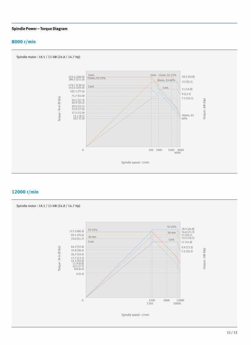
Spindle Power – Torque Diagram
8000 r/min
12000 r/min
Spindle motor : 18.5 / 11 kW (24.8 / 14.7 Hp)
Spindle motor : 18.5 / 11 kW (24.8 / 14.7 Hp)
0 1200010000
15001350
4000
117.0 (86.3)95.5 (70.5)70.0 (51.7)
44.2 (32.6)35.8 (26.4)26.3 (19.4)17.7 (13.1)14.3 (10.6)
11.9 (8.8)10.5 (7.7)
6 (4.4)
8.8 (6.5)
18.5 (24.8)16.6 (22.3)
13.5 (18.1)
9.9 (13.3)
15 (20.1)
11 (14.8)
7.5 (10.1)
S3 25%
Cont.
30 min
S3 25%
Cont.
30 min
71.7 (52.9)
105.1 (77.6)
30.0 (22.1)
17.5 (12.9)
286.5 (211.4)
143.4 (105.8)
50.5 (37.3)
23.9 (17.6)
40.9 (30.2)
353.4 (260.8)
176.7 (130.4)
7.5 (10.1)
30min, S360%
11 (14.8)
9 (12.1)
15 (20.1)
18.5 (24.8)
10.7 (7.9)
500 3500
13.1 (9.7)
10006000
80000
5min15min, S3 15%
15min, S3 15%
Cont. Cont.
30min, S3 60%
5min
Torq
ue :
N. m
(ft-
lbs)
Out
put :
kW
(Hp)
Spindle speed : r/min

14 /
External Dimensions
HC Ⅱ series
Front View
Top View
Unit : mm (inch)
Pallet Dimensions
HC 400 Ⅱ HC 500 Ⅱ
Model A B C D E F G
HC 400 Ⅱ 2260 (89) R 364 (14.3) R 732 (28.8) 620 (24.4) 3666 (144.3) 2822 (111.1) 5240 (206.3)
HC 500 Ⅱ 2625 (103.3) R 364 (14.3) R 544 (21.4) 630 (24.8) 4093 (161.1) 2993 (117.8) 6073 (239.1)
M16
50(1.9)
50(1.9)
24-M16X2 TAP, DP30
75(2.9)
75(2.9)
500 (19.7)
500
(19.
7)
50 (1.9
)50 (1.9
)
EDGE-LOCATOR M16
24-M16 x 2 TAP, DP30
55(2.1)
55(2.1)
40(1.6) 400 (15.7)
40(1.6)
36 (1.4)18 (0.7)
40 (1.6
)40 (1.6
)40
0 (1
5.7)
25 (0
.9)
100 x
4 =
400
(15.
7)
100 x 4 = 400 (15.7)
25
3618
80 x 4 = 320 (12.6)
80 x
4 =
320
(12.
6)
F
G
B
C D
A
E
HC Ⅱ
series
Product Overview
Basic Information
Basic Structure
Detailed
Information
Options
Applications
Capacity Diagram
Specifications
Customer Support
Service

15 14 /
Machine Specifications
Description Unit HC 400Ⅱ HC 500Ⅱ
Machining
CapacityTravel distance
X-axis mm (inch) 600 (23.6) 850 (33.5)
Y-axis mm (inch) 560 (22) 700 (27.6)
Z-axis mm (inch) 565 (22.2) 750 (29.5)
Distance from spindle nose to table center mm (inch) 150 ~ 715 (5.9 ~ 28.1) 150 ~ 900 (5.9 ~ 35.4)
Distance from spindle center to table top mm (inch) 50 ~ 610 (1.9 ~ 24) 50 ~ 750 (1.9 ~ 29.5)
Feedrate
Rapid Feedrate
X-axis m/min (ipm) 40 (1574.8)
Y-axis m/min (ipm) 40 (1574.8)
Z-axis m/min (ipm) 40 (1574.8)
Cutting feedrate mm/min (ipm) 40000 (1574.8)
Pallet Pallet type 24-M16 X P2.0
Pallet indexing angle deg 1 {0.001}*
Max. loading capacity kg (lb) 400 (881.8) 500 (1102.3)
Max. workpiece size mm (inch) 600 x 800 (23.6 x 31.5) 800 x 900 (31.5 x 35.4)
Pallet size mm (inch) 400 x 400 (15.7 x 15.7) 500 x 500 (19.7 x 19.7)
Spindle Max. spindle speed r/min 8000 {12000}*
Data specification ISO #40, 7/24 TAPER
Max. torque N·m (ft-lbs) 1034 {1444} (368.8 {1065})* 1732 {1444} (1277.5 {1065})*
Automatic
Pallet
Changer
(APC)
No. of pallets ea 2
Pallet change time s 8 8.5
Indexing angle (rotation) deg 90
Automatic
Tool
Changer
(ATC)
Tool shank type BT40 {CAT40 / DIN 40 / HSK-A63}*
Tool storage
capacity
ea 40 {60 / 80 / 120}*
Matrix Type ea {170 / 262}*
Max. tool
diameter
W/O adjacent tool mm (inch) 75 (2.9)
With adjacent tool mm (inch) 140 (5.5)
Max. tool length mm (inch) 300 (11.8) 400 (15.7)
Max. tool weight kg (lb) 10 (22)
Tool change time (T-T-T, tool weight less than 12K) s 1.5
Tool change time (C-T-C, tool weight less than 12K) s 4
Motor Spindle motor power kW (Hp) 18.5 / 11 (24.8 / 14.7)
Power
SourcePower consumption kVA 58
Compressed air pressure Mpa (psi) 0.54 (78.3)
Tank
CapacityCoolant tank capacity L (galon) 550 (145.3) 640 (169.1)
Lube tank capacity L (galon) 1.4 (0.37)
Machine
DimensionsHeight mm (inch) 2830 (111.4) 3000 (118.1)
Length mm (inch) 4630 (182.3) 5320 (209.4)
Width mm (inch) 2260 (88.9) 2680 (105.5)
Weight kg (lb) 11000 (24250.8) 12500 (27557.8)
* { } : Option
HC Ⅱ series
16 /
HC Ⅱ
series
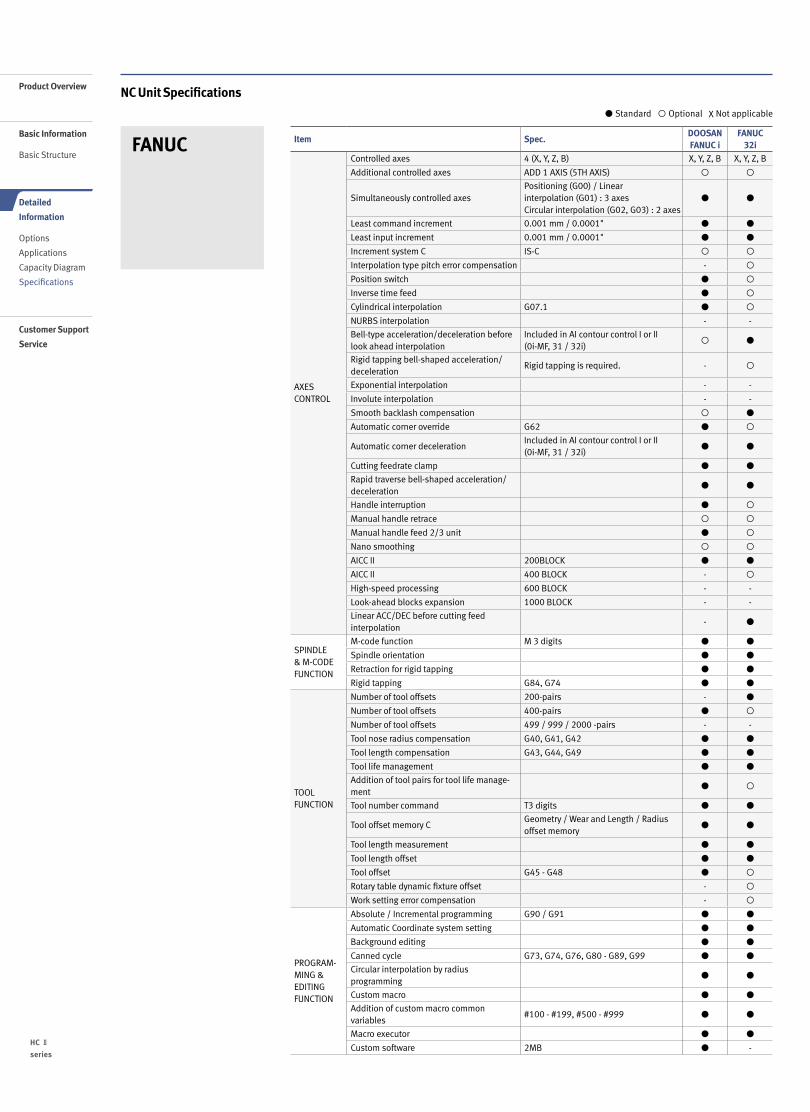
NC Unit Specifications
FANUC
Standard Optional X Not applicable
Item Spec.DOOSANFANUC i
FANUC 32i
AXES CONTROL
Controlled axes 4 (X, Y, Z, B) X, Y, Z, B X, Y, Z, B
Additional controlled axes ADD 1 AXIS (5TH AXIS)
Simultaneously controlled axes Positioning (G00) / Linear interpolation (G01) : 3 axes Circular interpolation (G02, G03) : 2 axes
Least command increment 0.001 mm / 0.0001"
Least input increment 0.001 mm / 0.0001"
Increment system C IS-C
Interpolation type pitch error compensation -
Position switch
Inverse time feed
Cylindrical interpolation G07.1
NURBS interpolation - -
Bell-type acceleration/deceleration before look ahead interpolation
Included in AI contour control I or II (0i-MF, 31 / 32i)
Rigid tapping bell-shaped acceleration/deceleration
Rigid tapping is required. -
Exponential interpolation - -
Involute interpolation - -
Smooth backlash compensation
Automatic corner override G62
Automatic corner decelerationIncluded in AI contour control I or II (0i-MF, 31 / 32i)
Cutting feedrate clamp
Rapid traverse bell-shaped acceleration/deceleration
Handle interruption
Manual handle retrace
Manual handle feed 2/3 unit
Nano smoothing
AICC II 200BLOCK
AICC II 400 BLOCK -
High-speed processing 600 BLOCK - -
Look-ahead blocks expansion 1000 BLOCK - -
Linear ACC/DEC before cutting feed interpolation
-
SPINDLE & M-CODE FUNCTION
M-code function M 3 digits
Spindle orientation
Retraction for rigid tapping
Rigid tapping G84, G74
TOOL FUNCTION
Number of tool offsets 200-pairs -
Number of tool offsets 400-pairs
Number of tool offsets 499 / 999 / 2000 -pairs - -
Tool nose radius compensation G40, G41, G42
Tool length compensation G43, G44, G49
Tool life management
Addition of tool pairs for tool life manage-ment
Tool number command T3 digits
Tool offset memory C Geometry / Wear and Length / Radius offset memory
Tool length measurement
Tool length offset
Tool offset G45 - G48
Rotary table dynamic fixture offset -
Work setting error compensation -
PROGRAM-MING & EDITING FUNCTION
Absolute / Incremental programming G90 / G91
Automatic Coordinate system setting
Background editing
Canned cycle G73, G74, G76, G80 - G89, G99
Circular interpolation by radius programming
Custom macro
Addition of custom macro common variables
#100 - #199, #500 - #999
Macro executor
Custom software 2MB -
Product Overview
Basic Information
Basic Structure
Detailed
Information
Options
Applications
Capacity Diagram
Specifications
Customer Support
Service

17 16 /
NC Unit Specifications
FANUC
Standard Optional X Not applicable
Item Spec.DOOSANFANUC i
FANUC 32i
PROGRAM-MING & EDITING FUNCTION
Custom software 4MB, 6MB -Custom software 8MB
Custom software 12MB, 16MB
Decimal point input
Extended P-code variables 256Kbyte - -Extended P-code variables 512Kbyte
Extended P-code variables 1Mbyte - -Extended part program editing
Part program storage 256KB(640m) -
Part program storage 512KB(1,280m)
Part program storage 1MB(2,560m) -
Part program storage 2MB(5,120m)
Part program storage 4MB(1,0240m) - -Part program storage 8MB(2,0480m) - -Inch/metric conversion G20 / G21
Label skip
Maximum commandable value ±99999.999mm(±9999.9999 inch)
Number of Registered programs 400 ea -Number of Registered programs 500 ea -
Optional block skip 1 BLOCK -
Optional block skip 9 BLOCK
Optional stop M01
Program file name 32 characters
Program number O4-digits -Sequence number N 8-digit N5 digit N8 digitPlayback function
Workpiece coordinate system G52 - G59
Addition of workpiece coordinate system G54.1 P1 - 48 (48 pairs)
Addition of workpiece coordinate system G54.1 P1 - 300 (300 pairs) -
Tilted working plane indexing command G68.2
OTHERS FUNCTIONS(Operation, setting & Display, etc)
Embeded Ethernet
MDI / DISPLAY unit 8.4" Color LCD, keyboard for data input(small), soft-keys - -MDI / DISPLAY unit 10.4" Color LCD, Keyboard for data input, soft-keys
MDI / DISPLAY unit 15" Color LCD, Keyboard for data input, soft-keys - -I/O interface RS - 232C
USB memory interface Only Data Read & Write
Stored stroke check 2
Multi language display
3rd / 4th reference return
Cs contouring control
Reader/Puncher interface (for 2ch)
Multi spindle control - -Retraction for 3-dimensional rigid tapping
Extended Spindle orientation(Spindle Multi Orientation)
Chopping function G81.1 -
High speed skip function
Polar coordinate command G15 / G16
Polar coordinate interpolation G12.1 / G13.1 -
Programmable mirror image G50.1 / G51.1
Scaling G50, G51
Single direction positioning G60
Pattern data input
Jerk control AI contour control II is required.
Fast Data server with1GB PCMCIA card
Fast Ethernet
3-dimensional coordinate conversion
3-dimensional tool compensation -
3-dimensional manual feed
Tape format for FS15 - -Tape format for FS10/11
Figure copying G72.1, G72.2 -
Machining time stamp function -
Machining quality level adjustment
EZ Guide I with 10.4" Color TFT- Doosan infracore Conversational Programming Solution - When the EZ Guide i is used, the Dynamic graphic display cannot application
Dynamic graphic display (with 10.4" Color TFT LCD)
- Machining profile drawing. - When the EZ Guide i is used, the Dynamic graphic display cannot application

18 /
Responding to Customers Anytime, Anywhere
Global Service Support Network
Technical Center: Sales Support, Service Support, Parts Support
5Corporations
3Factories
18Technical Centers
122Dealer Networks
AMERICA EUROPE
HC Ⅱ
series
Product Overview
Basic Information
Basic Structure
Detailed
Information
Options
Applications
Capacity Diagram
Specifications
Customer Support
Service

19 18 /
Doosan Machine Tools’ Global Network, Responding to Customer’s Needs nearby, Anytime, AnywhereDoosan machine tools provides a system-based professional support service before and after the machine tool sale by responding quickly and efficiently to customers’ demands.By supplying spare parts, product training, field service and technical support, we can provide top class support to our customers around the world.
We help customers to achieve success by providing a variety of professional services from pre-sales consultancy to post-sales support.
Customer Support Service
- On site service- Machine installation and testing- Scheduled preventive maintenance- Machine repair
Field Services
- Supports machining methods and technology
- Responds to technical queries- Provides technical consultancy
Technical Support
- Programming / machine setup and operation
- Electrical and mechanical maintenance- Applications engineering
Training
- Supplying a wide range of original Doosan spare parts
- Parts repair service
Supplying Parts
Domestic Service Support Network
2Integrated Support Centers 7
Sales Branch Offices
6Post-Sales Service Centers 31
Designated Repair Service Centers
CHINA (Yantai)
CHINA (Shanghai)
INDIA
Changwon FactoryHead Office
JAPAN

Major Specifications
HCⅡseries Specification Unit HC 400Ⅱ HC 500Ⅱ
Pallet size mm (inch) 400 x 400 (15.7 x 15.7) 500 x 500 (19.7 x 19.7)
Taper specification taper 40 40
Max. spindle speed r/min 8000 8000
Spindle power kW (Hp) 18.5 (24.8) 18.5 (24.8)
Travel distance (X-axis / Y-axis / Z-axis) mm (inch) 600 / 560 / 565 (23.6 / 22 / 22.2) 850 / 700 / 750 (33.4 / 27.5 / 29.5)
Tools ea 40 40
NC system - FANUC FANUC
Doosan Machine Tools
Head OfficeYeonkang Bldg., 6th FL., 270, Yeonji-dong,
Jongno-gu, Seoul, Korea
Tel +82-2-3670-5345 / 5362
Fax +82-2-3670-5382
Doosan Machine Tools America19A Chapin Rd., Pine Brook, NJ 07058, U.S.A.
Tel +1-973-618-2500
Fax +1-973-618-2501
http://www.doosanmachinetools.com www.facebook.com/doosanmachinetools
Doosan Machine Tools ChinaRoom 101,201,301, Building 39 Xinzhuan Highway
No.258 Songjiang District,China Shanghai(201612)
Tel +86 21-5445-1155
Fax +86 21-6405-1472
Doosan Machine Tools EuropeEmdener Strasse 24, D-41540 Dormagen, Germany
Tel +49-2133-5067-100
Fax +49-2133-5067-111
Doosan Machine Tools Japan#2412, Mita Kokusai Bldg. 1-4-28 Mita,
Minato-ku, Tokyo 108-0073, Japan
Tel +81 3 5730 9013
Fax +81 3 5730 9016
Doosan Machine Tools India106 / 10-11-12, Amruthahalli, Byatarayanapura,
Bellary road, Bangalore-560 092, India
Tel +91-80-4266-0122 / 121 / 100
For more details, please contact Doosan Machine Tools. The specifications and information above-mentioned may be changed without prior notice. Doosan Machine Tools Co., Ltd. is a subsidiary of MBK Partners. The trademark is used under a licensing agreement with Doosan Corporation,
the registered trademark holder.


![General Specifications - Yokogawacdn2.us.yokogawa.com/GS33K55R40-50E.pdf · General Specifications [Release 5] GENERAL ... Contact](https://img.dokumen.tips/doc/110x75/5aa604cc7f8b9a1d728deb53/general-specications-specications-contents-index-release-5-general-.jpg)