Embed Size (px)
Citation preview
4
2
31
4 3
21
1234
4 3
21
3421
12
34
4 3
21
1234
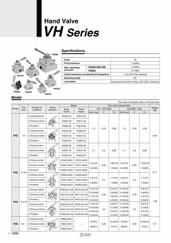
Hand Valve
VH Series
Max. operatingpressure
Air
1.5 MPa
1.0 MPa
0.7 MPa
–5 to 60°C (No freezing)
90°
Not required (Use turbine oil Class 1 ISO VG32, if lubricated.)
Fluid
Proof pressure
Ambient temperature and operating fluid temperature
Operating angle
Lubrication
VH600VH200/300/400
Specifications
VH410
VH240VH210
VH600
VH310VH220
Model
Series
VH2
VH3
VH4
VH6
Portsize
Number of positions
Pipingdirection
Model Flow rate characteristic
Bodymount
Panelmount b CvC[dm3/(s·bar)] b CvC[dm3/(s·bar)]
1(P)→2(A)/4(B) 2(A)/4(B)→3(R) Weight(kg)
1/4
1/4, 3/8
1/4 to 3/4
3/4, 1
VH200-02
VH201-02
VH202-02
VH240-02
VH241-02
VH242-02
VH220-02
VH221-02
VH222-02
VH300-02/03
VH301-02/03
VH302-02/03
VH320-02/03
VH321-02/03
VH322-02/03
VH400-02 to 06
VH401-02 to 06
VH402-02 to 06
VH420-02 to 06
VH421-02 to 06
VH422-02 to 06
VH600-06/10
VH601-06/10
VH602-06/10
VH210-02
VH211-02
VH212-02
VH250-02
VH251-02
VH252-02
VH230-02
VH231-02
VH232-02
VH310-02/03
VH311-02/03
VH312-02/03
VH330-02/03
VH331-02/03
VH332-02/03
VH410-02 to 06
VH411-02 to 06
VH412-02 to 06
VH430-02 to 06
VH431-02 to 06
VH432-02 to 06
1.5
1.1
5.4(1/4)
6.4(3/8)
4.5(1/4)
5.3(3/8)
14.3(1/4)
15.6(3/8)
17.5(1/2)
18.4(3/4)
11.9(1/4)
13.0(3/8)
14.6(1/2)
15.4(3/4)
37(3/4)
38.8(1)
0.25
0.2
0.25
0.2
0.25
0.2
0.25
0.38
0.28
1.25(1/4)
1.5(3/8)
1.1(1/4)
1.3(3/8)
3.4(1/4)
3.8(3/8)
4.3(1/2)
4.5(3/4)
2.9(1/4)
3.1(3/8)
3.5(1/2)
3.7(3/4)
10.2(3/4)
10.5(1)
1.5
1.1
5.4(1/4)
6.4(3/8)
4.5(1/4)
5.3(3/8)
14.3(1/4)
15.6(3/8)
17.5(1/2)
18.4(3/4)
11.9(1/4)
13.0(3/8)
14.6(1/2)
15.4(3/4)
37(3/4)
38.8(1)
0.25
0.2
0.25
0.2
0.25
0.2
0.25—
0.42
0.71
1.28
9.7
3 (Closed center)
3 (Exhaust center)
2 (Position)
3 (Closed center)
3 (Exhaust center)
2 (Position)
3 (Closed center)
3 (Exhaust center)
2 (Position)
3 (Closed center)
3 (Exhaust center)
2 (Position)
3 (Closed center)
3 (Exhaust center)
2 (Position)
3 (Closed center)
3 (Exhaust center)
2 (Position)
3 (Closed center)
3 (Exhaust center)
2 (Position)
3 (Closed center)
3 (Exhaust center)
2 (Position)
0.38
0.28
1.25(1/4)
1.5(3/8)
1.1(1/4)
1.3(3/8)
3.4(1/4)
3.8(3/8)
4.3(1/2)
4.5(3/4)
2.9(1/4)
3.1(3/8)
3.5(1/2)
3.7(3/4)
10.2(3/4)
10.5(1)
The value in brackets refers to the port size.
1696C
4
2
31
4 3
21
1234
4 3
21
3421
12
34
4 3
21
12
12
14
14 12
14
Symbol
(B)4
1(P)
(B)4
1(P)
(B)4
1(P)
Exhaust center
Closed center
2 position
(A)2
3(R)
(A)2
3(R)
(A)2
3(R)
Flow direction
4(B)90° 45° 45°
N
2 position 3 positionFlow
direction2 (A)
Flow direction
2 (A)
Flow direction
4(B)
(Refer to the figures of piping direction to the right.)
Handle Operation Angle and Air Flow Direction
1234
0.9 0.7
0.5
2000
0.1
0.2
0.3
0.4
0.5
0.6
0.7
0.8
0.1
0.2
0.30.4
0.4
0.1
0.2
0.3
0.4
0.5
0.6
4000 6000
0.6
0.7
0.8
0.9
0.1
0.2
0.3
10 15
0.5
0.6
1.0
1000
0.6
0.9
0.1
0.2
0.3
0.4
0.5
0.6
0.7
0.8
0.7
0.10.2
0.3
0.40.5
1.0
1.0
2000
0.7
0.80.9
1.0
0.8
0.9
200 400
0.1
0.2
0.3
0.4
0.5
0.6
0.7
0.8
0.10.2
0.30.4
0.5
0.60.7
1.0
600 800 1000
0.9
1.0
0 0
0 0 5
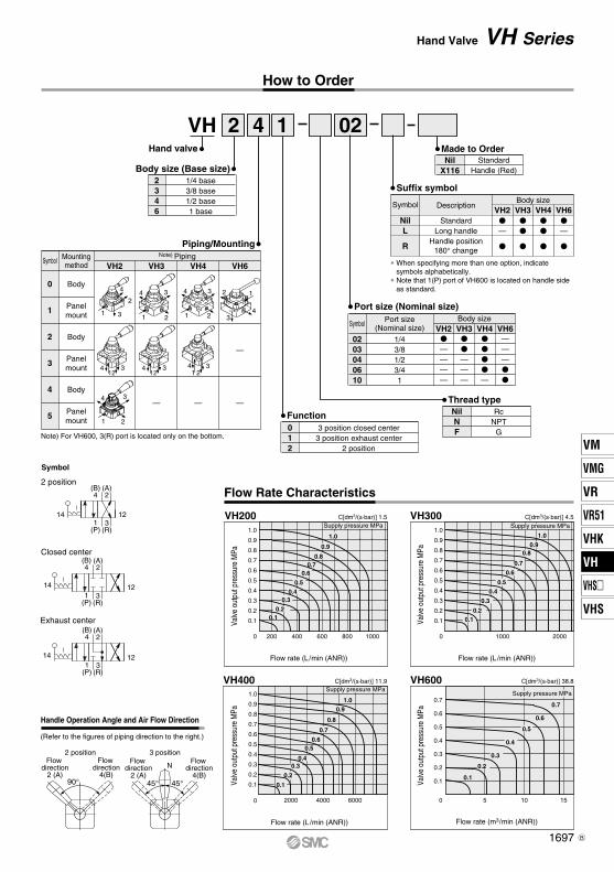
How to Order
VH200 VH300
VH400 VH600
Valve
out
put p
ress
ure
MPa
Valve
out
put p
ress
ure
MPa
Valve
out
put p
ress
ure
MPa
C[dm3/(s·bar)] 1.5 C[dm3/(s·bar)] 4.5
C[dm3/(s·bar)] 38.8C[dm3/(s·bar)] 11.9
Flow Rate Characteristics
Valve
out
put p
ress
ure
MPa
Flow rate (L/min (ANR))
Flow rate (m3/min (ANR))
Flow rate (L/min (ANR))
Flow rate (L/min (ANR))
Supply pressure MPa
Supply pressure MPa Supply pressure MPa
Supply pressure MPa
VH 2 4 1 02
Suffix symbol
NilL
R
VH2 VH3 VH4 VH6Description
StandardLong handle
Handle position180° change
—
—
Body sizeSymbol
NilX116
StandardHandle (Red)Body size (Base size)
2346
1/4 base3/8 base1/2 base1 base
∗ When specifying more than one option, indicate symbols alphabetically.
∗ Note that 1(P) port of VH600 is located on handle sideas standard.
Made to Order
—
———
Piping/Mounting
Symbol
0
1
2
3
4
5
Note) PipingMountingmethod
Body
Body
Body
Panelmount
Panelmount
Panelmount
VH2 VH3 VH4 VH6
Hand valve
Note) For VH600, 3(R) port is located only on the bottom.
Body size
Port size (Nominal size)
0203040610
1/43/81/23/41
Function012
3 position closed center3 position exhaust center
2 position
Thread typeNilNF
RcNPT
G
Port size(Nominal size)Symbol
VH2 VH3 VH4 VH6
————
———
———
—
1697
Hand Valve VH Series
VM
VMG
VR
VR51
VHK
VH
VHS
VHS
VH
B

q
w
r
i
e
t
e
t
y
q
o
u
w
!0
q
w
o
u y
r
iVH200
VH300/400
VH600
!0
No.
12
DescriptionMaterial
Replacement Parts
No. Component partsDescription
34567896789
10
10Handle
Material
Structural steel
Structural steel
VH200 VH300 VH400
24403A 24413A 24413A
244036A 244125A 244125A
KT-VH2-N KT-VH3-N KT-VH4-N
Part No. of Lock Nutfor Panel Mount
SeriesVH200VH300VH400
Part no.
Note) Not applicable to the VH600 series.
Component Parts
CoverBody
VH200/300/400Zinc die-casted
Aluminium die-casted
VH600Cast ironCast iron
Slide ringSlide ring springO-ringHandle head
Handle head
Resin
Piano wireNBR
Zinc alloyPiano wire
Part no.
Note) Replacement parts for the VH600 series are not available.∗ Including grease.
244032—
244035
244032
244127244035
244032244223244035
24401024418
240258Maintenanceand repair kit ∗
Handle headassembly ∗
Handle headassembly ∗
SpringPinSteel ball
Spring
Pin
StandardLong typeRed
Steel ball
Handle
SUJZinc alloyPiano wire
SUJ—
—
Construction
z(P)x(A) v(B)
c(R
)
v(B) x(A)
z(P)
c(R
)
v(B) x(A) z(P) c(R)
1698
VH Series
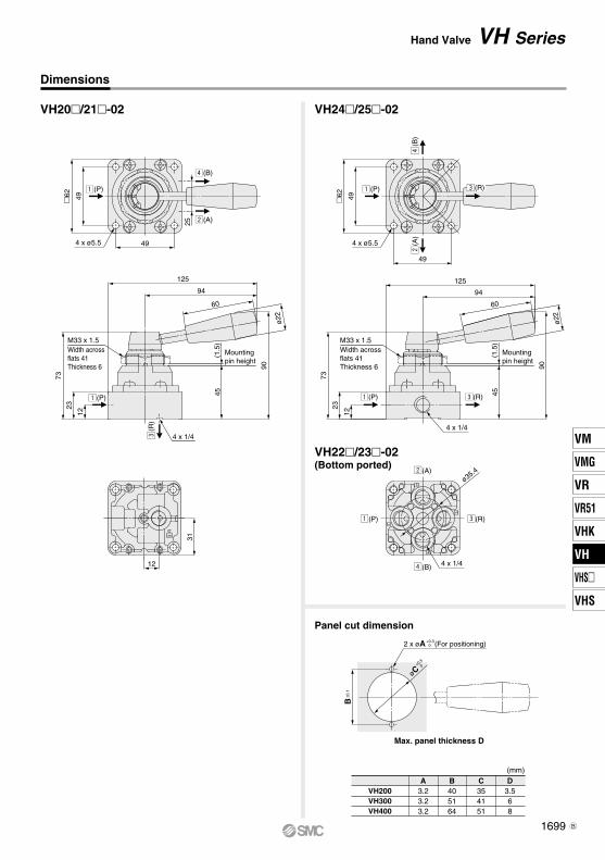
VH20/21-02 VH24/25-02
R3
4
1
2
3
Dimensions
31
12
Panel cut dimension
(mm)
VH200VH300VH400
A3.23.23.2
B405164
C354151
D3.568
Max. panel thickness D
4 x ø5.5
4962
z(P)
49
v(B)
25 x(A)
z(P)
M33 x 1.5Width acrossflats 41Thickness 6
12
23
73
94
125
60
45
4 x 1/4
Mountingpin height
c(R
)
M33 x 1.5Width acrossflats 41Thickness 6
v(B
)
+0.5
øC 0
2 x øA (For positioning)+0.30
B±0
.1
z(P)
x(A
)
c(R)
z(P) c(R)
49
4962
4 x ø5.5
12
23
73
4 x 1/4
94
125
90
60
ø22
4
2
N
c(R)z(P)
x(A)
v(B) 4 x 1/4
ø35.4
(1.5
)
45
Mountingpin height
(1.5
)
VH22/23-02(Bottom ported)
ø22
90
1699
Hand Valve VH Series
VM
VMG
VR
VR51
VHK
VH
VHS
VHS
VH
B

c(R)
v(B)
z(P)
x(A)
Dimensions
VH30/31-02 to 03( ): Long handle type
VH32/33-02 to 03(Bottom ported)
Width acrossflats 50Thickness 8
z(P)
M40 x 1.5
13.5
27
88.5
4 x 1/4, 3/8
97(122)
134(159)
60
ø22
105(
109)
c(R)
56
4 x ø6.6
6274
z(P)
62
x(A
)v
(B)
c(R)
Mountingpin height
(1.5
)
Refer to page 1699 for the panel cut dimension.4 x 1/4, 3/8
ø44
1699-1
Hand Valve VH Series
VM
VMG
VR
VR51
VHK
VH
VHS
VHS
VH
B

R3
A2
P1
B4
z(P) c(R)
x(A)
v(B)
c(R)
x(A)
v(B)
z(P)
Refer to page 1699 for the panel cut dimension.
4 x ø6.6
102
89
z(P)
81
94
v(B
)x
(A)
c(R)
97(145)
144(191)
60
ø22
122(
130)
65
c(R)
M50 x 1.5Width acrossflats 63Thickness 8
Width acrossflats 63Thickness 8
1725
105.
5
z(P)
4 x 1/4, 3/8, 1/2
M50 x 1.5
2
19
107.
5
z(P)
97(145)
144(191)
60
4 x 3/4
c(R)
x(A
)
4 x ø6.5
88
88
10
2 z(P)
v(B
)
c(R)
Mountingpin height
ø22
124(
132)
4 x 1/4, 3/8, 1/2 4 x 3/4
ø86ø54
ø46
(1.5
)
67
Mountingpin height
(1.5
)
Dimensions
VH40/41-02 to 04 VH40/41-06
VH42/43-06(Bottom ported)
VH42/43-02 to 04(Bottom ported)
( ): Long handle type ( ): Long handle type
1700
VH Series
B

4
2
N
Hand Valve VH Series
VH600-06/10
Dimensions: Body Mount
4 x ø11
132
15
2
132
v(B
)
z(P)
ø32
x(A
)
48
25
150
76
223
300
40
4 x Rc3/4,1
c(R
)
151
ø15
1701
VM
VMG
VR
VR51
VHK
VH
VHS
VHS
VH

VH SeriesSpecific Product PrecautionsBe sure to read this before handling the products.Refer to back page 50 for Safety Instructions and pages 3 to 9 for 3/4/5 PortSolenoid Valve Precautions.
Design Piping
Warning Caution
Selection
Warning
Caution
Environment
Warning
1. Not suitable for use as a selector valve or a divider valve.The valve can malfunction due to air leakage.
2. Not suitable for negative pressure. The valve can malfunction due to air leakage.
3. Do not supply air pressure from other ports than 1(P) port.Air leakage may occur when the pressure is supplied from other ports.
1. Use in low temperature environmentsThe valve can be used at a temperature down to –5°C. Take appropriate measures to avoid freezing of drainage, moisture, etc.
2. Operation methodThe valve must be switched to each position instantly and securely. Stopping the handle halfway between the extreme positions may cause malfunction.
3. Switch the valve by handIf a hammer or other tools are used, or it is operated mechanically through the use of a cylinder or the like, damage could result.
1. Intermediate stopWhen stopping the cylinder piston in the middle using the3 position closed center valve, it is not possible to stop itcorrectly and precisely as the hydraulic equipment due to theair compressibility. Do not use this valve because it has slightair leakage and can not hold a stopping position. When it isnecessary to hold a stopping position, select an equipment toprevent displacement and design the circuit.
1. Ensure connection so that air is supplied to the port “1(P)” port.Air leakage may occur when the pressure is supplied from other ports.
1. When the valve is exposed to a large amount of dust, install a silencer into the port “3(R)”. When dust enters the valve from the port “3(R)”, it may cause air leakage.
1704

Hand Valve with Lock MechanismVH2mm/3mm/4mm-m-X256
Provided with handle lock mechanism.Hand valve has a structure in which the handle does not move without push-ing the lock lever. This prevents change-over due to accidental operation.
Fluid Air
Proof pressure 1.5 MPa
Max. operating pressure 1.0 MPa
Ambient temperature and operating fluid temperature −5 to 60°C (No freezing)
Operating angle 90°
Specifications The flow rate characteristics are the same as the standard product. Refer to the Web Catalog.
Lock lever
Port size 4 x 1/4, 3/8, 1/2
Handle
Lock lever
Push the lock lever and…
Handle operation becomes possible!* Operate the handle with the lock lever pushed.
Unlocked
Features
To ensure the safest possible operation of this product, please be sure to thoroughly read the “Safety Instructions” in our “Best Pneumatics” catalog before use.Caution
©2016 SMC Corporation All Rights Reserved
4-14-1, SOTO-KANDA, CHIYODA-KU, TOKYO 101-0021, JAPAN URL: http://www.smcworld.com
P.G. informationPoint to Group
Specialized ProductContact our sales office for delivery dates and prices as this is a special model.
P: UXSP163X-005E

VH X2560 022 1
How to Order
Body size2 1/4 base
3 3/8 base
4 1/2 base
Switching method
0
3-position closed center
12
(R)(P)
(A)(B)24
31
14
Flow direction2(A)
Flow direction4(B)
45°
45°
N
1
3-position exhaust center
3(R)
1(P)
(A)2
(B)4
14 12
Flow direction2(A)
Flow direction4(B)
45°
45°
N
2
2-position
123
(R)1
(P)
(A)2
(B)4
14
Flow direction2(A)
Flow direction4(B)
90°
Thread typeNil Rc
N NPT
F G
Port size
Symbol Port sizeBody size
VH2 VH3 VH4
02 1/4 V V V
03 3/8 — V V
04 1/2 — — V
Piping/Mounting
SymbolMounting method
Piping
VH2 VH3 VH4
0 Body4
2
31
4 3
21
4 3
211 Panel
mount
* For VH2mm, 3(R) port is located on the bottom.
Handle position
Nil 1
R 1
Hand Valve with Lock MechanismVH2mm/3mm/4mm-m-X256 P.G. information
Point to GroupSpecialized Product
1 P
45
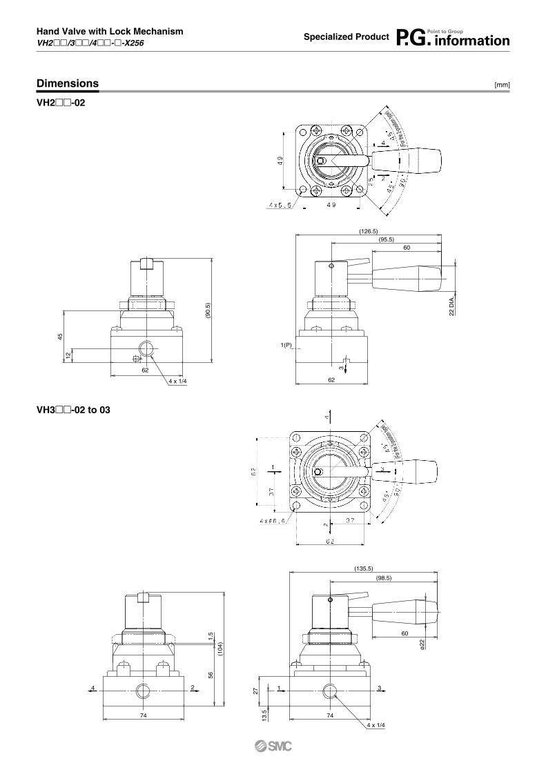
(90.
5)
60
22 D
IA.
(95.5)(126.5)
12
62
62
3
4 x 1/4
1(P)
(For th
e 2-po
sition
type)
(135.5)
(104
)
ø22
60
(98.5)
1.5
56
27
13.574 74
4 x 1/4
1 34 2
(For th
e 2-po
sition
type)
Dimensions [mm]
VH3mm-02 to 03
VH2mm-02
Hand Valve with Lock MechanismVH2mm/3mm/4mm-m-X256 P.G. information
Point to GroupSpecialized Product