Embed Size (px)
Citation preview
SL1100 Installation Instructions
1-888-632-3794 • [email protected] 1
Thank you for choosing NEC SL1100 Distributors!
This Installation Packet is Organized into Five Chapters:
BLUE: Hardware Installation Overview (Block Wiring, Music On-Hold, Paging, Door Box & Relays)
GREEN: Connecting to an SL1100 that is not on a network
ORANGE: Connecting to an SL1100 that is on a network [NO VoIP Card]
PINK: Connecting to an SL1100 that is on a network [HAS VoIP Card]
YELLOW: Recording Voicemail Greetings
Your System has been Pre-Loaded with the Following:
The Latest NEC SL1100 Software Version
Our Time Tested Default Programming
CPU Battery
All Expansion Cards included with this Purchase
Any InMail Voicemail Card included with this Purchased
FREE Music On-Hold (requires an InMail voicemail card)
Visit our Website for the Following:
Important Tech Notes, Tech Tips and Video Tutorials
PC PRO System Administrator Software
DESI Labeling Software
At any time during your installation or programming, please feel free to contact our tech support staff.
Tech Support: Call toll free 1-888-632-3794
Email Questions To: [email protected]
Tech Support Hours: Monday-Thursday 9am–6pm (EST), Friday 9am–5pm (EST)

Hardware Installation
Overview

SL1100 Hardware Installation
1-888-632-3794 • [email protected] 1
Wiring the 66-Installation Block
101–
–
–
–
–
–
–
–
102
103
104
105
106
107
108
–
–
–
–
–
–
–
–
–
–
–
–
–
––
–
1–
–
–
–
–
–
–
–
–
–
––
2
3
4
NOT
USED
Cable Plug 18 Port Digital Station Card(1100020)
ROW 3
TELCO (CO) LINES 1 - 4
SUGGESTED CABLE CONFIGURATION: STATIONS 101 - 108
PUNCH STAT ION JACK CABLETO TH IS ROW
Cable Plug 28 Port Digital Station Card(1100020)
Cable Plug 3Optional Digital/Analog Cardor Door Box Ports
Cable Plug 54 Port Analog Line Card(Inside Every SL1100 KSU)
Cable Plug 6Optional Analog or CO Ports
Cable Plug 4Optional Digital/Analog Cardor Door Box Ports

SL1100 Hardware Installation
1-888-632-3794 • [email protected] 2
Installing an External Music Source
Your system provides two connections for music sources. Use these music sources for Background Music and
Music On-Hold. Be sure the connected music sources are compatible with the following music input
specifications - Input Impedance: 600 Ohms @ 1 kHz. Output Impedance: 600 Ohms. Output Level: Nominal
250 mV (-10 dBm).
To Connect a Music Source (MOH or BGM):
1. Find the mono audio minijack (1/8”) that was supplied for Free with this phone system
2. There are two inputs for music sources – music on hold (MOH), and background music (BGM)
3. Plug the mono audio minijack into the MOH (Music on Hold) input on the SL1100 Motherboard and plug the other end of the audio cable into your music source
4. Plug the mono audio minijack into the BGM (Background Music) input on the SL1100 Motherboard and plug the other end of the audio cable into the music source
Audio IN/OUT Jack
BGM MOH PAGE
PAGE : Audio in/out (Externa l paging)MOH : Audio in (External MOH)BGM : Audio in (BGM)
A FREE Music On-Hold has been pre-installed on your system if you purchased an InMail Voicemail Card!
(Mono Audio Jack has ONE Black Band)
A 1/8” Mono to 1/8” Mono/RCA Cable was Included Free with your System.

SL1100 Hardware Installation
1-888-632-3794 • [email protected] 3
Installing External Paging
This Phone System provides and External Paging output. You connect the Phone System Paging output to an
audio input on a customer provided Paging system. Be sure the connected paging equipment is compatible
with the following page output specifications – Output Impedance: 600 Ohms @ 1 kHz. Output Level: Nominal
250 mV (-10 dBm).
To Connect to an External Paging Amplifier:
1. Find the mono audio minijack (1/8”) that was supplied for Free with this phone system
2. Plug the mono audio minijack into the PAGE input on the Phone System
3. Plug the other end of the audio cable into the paging amplifier
Audio IN/OUT Jack
BGM MOH PAGE
PAGE : Audio in/out (Externa l paging)MOH : Audio in (External MOH)BGM : Audio in (BGM)
(Mono Audio Jack has ONE Black Band)
A 1/8” Mono to 1/8” Mono/RCA Cable was Included Free with your System.
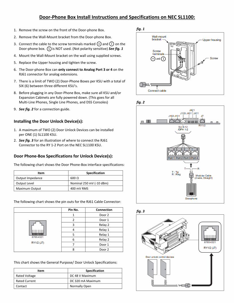
Door‐Phone Box Install Instructions and Specifications on NEC SL1100:
1. Remove the screw on the front of the Door‐phone Box.
2. Remove the Wall‐Mount bracket from the Door‐phone Box.
3. Connect the cable to the screw terminals marked and on the Door‐phone box. is NOT used. (Not polarity sensitive) See fig. 1
4. Mount the Wall‐Mount bracket on the wall using supplied screws.
5. Replace the Upper housing and tighten the screw.
6. The Door‐phone Box can only connect to Analog Port 3 or 4 on the RJ61 connector for analog extensions.
7. There is a limit of TWO (2) Door‐Phone Boxes per KSU with a total of SIX (6) between three different KSU’s.
8. Before plugging in any Door‐Phone Box, make sure all KSU and/or Expansion Cabinets are fully powered down. (This goes for all Multi‐Line Phones, Single Line Phones, and DSS Consoles)
9. See fig. 2 for a connection guide.
Installing the Door Unlock Device(s):
1. A maximum of TWO (2) Door Unlock Devices can be installed per ONE (1) SL1100 KSU.
2. See fig. 3 for an illustration of where to connect the RJ61 Connector to the RY 1‐2 Port on the NEC SL1100 KSU.
Door Phone‐Box Specifications for Unlock Device(s):
The following chart shows the Door Phone‐Box interface specifications:
Item Specification
Output Impedance 600 Ω Output Level Nominal 250 mV (‐10 dBm)
Maximum Output 400 mV RMS
The following chart shows the pin outs for the RJ61 Cable Connector:
Pin No. Connection
1 Door 2
2 Door 1
3 Relay 2
4 Relay 1
5 Relay 1
6 Relay 2
7 Door 1
8 Door 2
This chart shows the General Purpose/ Door Unlock Specifications:
Item Specification
Rated Voltage DC 48 V Maximum
Rated Current DC 320 mA Maximum
Contact Normally Open
I
fig. 1
I and
L
fig. 2
fig. 3

Connecting to an SL1100 That is NOT on a Network
The following Steps can be found in a Video Tutorial at
www.NECSL1100Distributors.com/quickstart
Phone System DOES NOT Have a VoIP Card

SL1100 Installation Instructions
1-888-632-3794 • [email protected] 1
Connecting to an SL1100 that is NOT on a Network and DOES NOT Have a VoIP Card:
Requirements:
Two (2) Ethernet Cables. (We’ve include one Free Ethernet Cable with this purchase)
Windows XP, Vista or Windows 7
PC PRO System Administrator Software (Available in the Downloads Section on necsl1100distributors.com)
One router (We recommend the EnGenius ESR300 Router)
Part 1: Assigning an IP Address
1. Connect the first Ethernet Cable from your computer (must be a PC, not a MAC) to a LAN port on your Router (NOT the WAN Port).
2. Connect the second Ethernet Cable from the Ethernet Port on the CPU Card of the SL1100 to another LAN port on the router. (See the diagram of the SL1100’s Ethernet Port below)

SL1100 Installation Instructions
1-888-632-3794 • [email protected] 2
3. For this example your router should either be plugged directly into a modem OR not plugged into a modem at all. AT NO POINT should your router be plugged into another router! The Router is only being used to assign IP addresses for PC Pro programming purposes.
4. Turn on the NEC SL1100 and wait for the phones and KSU to power up (approx. 3-5 minutes).
5. Go to any phone and press the Menu Key, then 96. (The Menu Key is the unmarked Circular Button on the lower right corner on the front of the phone)
6. Press Menu again to display the System IP Address.
7. Write down the IP address. This will be the IP Address used in PC Pro to connect to the phone system. SYSTEM IP ADDRESS: ________________________________
Part 2: Connecting to the SL1100 with the PC PRO System Administrator
1. Open the PC Pro System Administrator on the computer that is connected to the same router as the phone system.
2. Click the Connect Button in the upper left-hand corner.
3. Under Connection Type, Enter the SYSTEM IP Address you wrote down during Part 1.
4. Enter the User Name: sltech (all lower case with no spaces).
5. Enter the Password: 12345678 (no spaces or other characters).
6. Click connect.
SL1100 SYSTEM IP Address from Part 1
sltech
12345678

SL1100 Installation Instructions
1-888-632-3794 • [email protected] 3
7. IMPORTANT! Once connected, Click the Blue Download Arrow (top left hand portion of the window). This is an important step, to ensure that you don’t overwrite the phone system’s default
8. Click the Start Button to retrieve all the system data that is currently programmed by default.
9. Once the system data has been retrieved and downloaded, click the Close Button.
10. You have now connected, retrieved and downloaded the system data and are ready to make programming changes to your NEC SL1100.

Connecting to an SL1100
That IS on a Network
The following Steps can be found in a Video Tutorial at
www.NECSL1100Distributors.com/quickstart
Phone System DOES NOT Have a VoIP Card

SL1100 Installation Instructions
1-888-632-3794 • [email protected] 1
Connecting to an SL1100 that IS on a Network but DOES NOT have a VoIP Card:
Part 1: Assigning and Creating IP Addresses
Requirements:
One (1) Ethernet Cable. (We’ve include a Free Ethernet Cable with this purchase)
Windows XP, Vista or Windows 7
The following instructions will determine the: Subnet Mask Address
Default Gateway Address
SL1100 System IP Address
Perform the following from a Computer on the Network:
1. Click the Start Button in the lower left corner of your screen.
2. In the search box Type cmd then Press Enter to launch the Command Prompt.
Type cmd Type cmd

SL1100 Installation Instructions
1-888-632-3794 • [email protected] 2
3. In the Command Prompt Window, Type ipconfig then Press Enter.
4. Locate the Subnet Mask Number and Write it Down.
SUBNET MASK: ________________________________
5. Locate the Default Gateway Number and Write it Down.
DEFAULT GATEWAY: ___________________________
In the next step you’ll need to create two (2) new IP Addresses on your network. The first will be assigned to the VoIP Card and the second will be reserved for Voice Ports (such as SIP trunks). In order to create these addresses, you’ll first need to see which IP Addresses are currently in use.
IMPORTANT! If you have an IT administrator, it is important to check with them and ensure that the addresses you create do not interfere with any others on the current network.

SL1100 Installation Instructions
1-888-632-3794 • [email protected] 3
6. In the Command Prompt Window, Type arp –a and Press Enter. This will display all of the IP Addresses currently in use on your Network.
7. Locate the Last DYNAMIC IP Address and create a brand new IP Addresses that immediately follow after that number. This IP Address will be the System IP Address of the SL1100.
Here’s an Example:
In the example picture above, the Last DYNAMIC IP Address is 192.168.1.5 so our new IP Addresses would be:
SYSTEM IP ADDRESS: 192.168.1.6 .
Based on YOUR Last DYNAMIC IP Address, write your new IP Addresses here:
SYSTEM IP ADDRESS: .
8. Again, if you have an IT Administrator, it is important to confirm with them that your two (2) new
addresses are available for use on your phone system and will not interfere with any other devices on your network.

SL1100 Installation Instructions
1-888-632-3794 • [email protected] 4
Part 2: Using a Phone to Assign the IP Addresses to the SL1100
Requirements: A phone connected to the SL1100 Phone System
The three (3) IP Addresses that you wrote down in Part 1
From a phone connected to the SL1100:
1. Press the Speaker Button.
2. Press # * # * (pound, star, pound, star).
3. When prompted for a password, Press 12345678.
4. Press the Menu Key. (The Menu Key is the unmarked Circular Button on the lower right corner on the front of the phone)
5. You will now see “Program Mode” on the phone’s display.
6. Using the dial pad, type 10-63-01 to enter DHCP Client Mode. Our pre-programmed system default has DHCP set to YES. Change this to NO by pressing the black key +1 soft key under the LCD display. This turns DHCP off.
7. Press the Menu Key.
8. Press the Mute key two times to back out of 10-63 programming.
9. Using the dial pad, type 10-12-01. You’ll be asked to enter the IP Address of the SL1100, so refer to the number you wrote down in Part 1, and type your SL1100 System IP Address.
10. You’ll automatically be entered into Programming Mode 10-12-02, where you will be asked to enter a Subnet Mask. Refer to the number you wrote down in Part 1, and type your Subnet Mask IP Address, then Press the Menu Key.
11. You’ll automatically be entered into Programming Mode 10-12-03 where you will be asked to enter your Default Gateway. Refer to the number you wrote down in Part 1, and type your Default Gateway IP Address.
UNPLUG THE SL1100 FROM ALL ETHERNET CONNECTIONS!

SL1100 Installation Instructions
1-888-632-3794 • [email protected] 5
12. Press the Mute Key Four Times to back out of 10-12 programming.
13. Press the Exit Key.
14. After 5 Minutes, Power off the Phone System.
15. Plug in your Ethernet Cable to the Ethernet Port on the CPU Card of the SL1100. (See the diagram of the SL1100’s Ethernet Port below)
16. Wait 2 Minutes Before Turning the Power Back On.
17. Turn the NEC SL1100 on and wait for the phones and KSU to power up (approx. 3-5 minutes).
GIVE THE PHONE SYSTEM 5 MINUTES TO SAVE CHANGES
Even though the phone’s display has come back up, the changes are still being written to the processor! Do NOT reboot the system during this time.
Also, IF this is a pre-existing phone system and it already has custom programming, we strongly recommend backing up the phone system’s database before continuing.

SL1100 Installation Instructions
1-888-632-3794 • [email protected] 6
18. Go to any phone and press the Menu Key, then 96.
19. Press the Menu Key Again.
20. You will now see that the top IP Address (System) has been updated with the address you entered. This is the IP Address you’ll enter in to the PC PRO System Administrator to connect to the system.
Part 3: Connecting to the SL1100 with the PC PRO System Administrator
Requirements:
PC PRO System Administrator Software (Available in the Downloads Section on necsl1100distributors.com)
1. Open the PC Pro System Administrator on the computer that is connected to the same router as the phone system.
2. Click the Connect Button in the upper left-hand corner.
3. Under Connection Type, Enter the SYSTEM IP Address you wrote down during Part 1.
4. Enter the User Name: sltech (all lower case with no spaces).
5. Enter the Password: 12345678 (no spaces or other characters).
6. Click connect.
SL1100 SYSTEM IP Address from Part 1
sltech
12345678

SL1100 Installation Instructions
1-888-632-3794 • [email protected] 7
7. IMPORTANT! Once connected, Click the Blue Download Arrow (top left hand portion of the window).This is an important step, to ensure that you don’t overwrite the phone system’s default settings.
8. Click the Start Button to retrieve all the system data that is currently programmed by default.
9. Once the system data has been retrieved and downloaded, click the Close Button.
10. You have now connected, retrieved and downloaded the system data and are ready to make programming changes to your NEC SL1100.

Connecting to an SL1100
That IS on a Network
The following Steps can be found in a Video Tutorial at
www.NECSL1100Distributors.com/quickstart
Phone System HAS a VoIP Card

SL1100 Installation Instructions
1-888-632-3794 • [email protected] 1
Connecting to an SL1100 that IS on a Network and HAS a VoIP Card:
Part 1: Assigning and Creating IP Addresses
Requirements:
One (1) Ethernet Cable. (We’ve include a Free Ethernet Cable with this purchase)
Windows XP, Vista or Windows 7
The following instructions will determine the: Subnet Mask Address
Default Gateway Address
VoIP Card and Voice Port IP Addresses
Perform the following from a Computer on the Network:
1. Click the Start Button in the lower left corner of your screen.
2. In the search box Type cmd then Press Enter to launch the Command Prompt.
Type cmd Type cmd

SL1100 Installation Instructions
1-888-632-3794 • [email protected] 2
3. In the Command Prompt Window, Type ipconfig then Press Enter.
4. Locate the Subnet Mask Number and Write it Down.
SUBNET MASK: ________________________________
5. Locate the Default Gateway Number and Write it Down.
DEFAULT GATEWAY: ___________________________
In the next step you’ll need to create two (2) new IP Addresses on your network. The first will be assigned to the VoIP Card and the second will be reserved for Voice Ports (such as SIP trunks). In order to create these addresses, you’ll first need to see which IP Addresses are currently in use.
IMPORTANT! If you have an IT administrator, it is important to check with them and ensure that the addresses you create do not interfere with any others on the current network.

SL1100 Installation Instructions
1-888-632-3794 • [email protected] 3
6. In the Command Prompt Window, Type arp –a and Press Enter. This will display all of the IP Addresses currently in use on your Network.
7. Locate the Last DYNAMIC IP Address and create two (2) brand new IP Addresses that immediately follow after that number. The first number will be used for the VoIP Card and the second number will be reserved for Voice Ports (such as SIP Trunks).
Here’s an Example:
In the example picture above, the Last DYNAMIC IP Address is 192.168.1.5 so our two new IP Addresses would be:
VOIP CARD: 192.168.1.6 .
VOICE PORTS: 192.168.1.7 .
Based on YOUR Last DYNAMIC IP Address, write your new IP Addresses here:
VOIP CARD: .
VOICE PORTS: .
8. Again, if you have an IT Administrator, it is important to confirm with them that your two (2) new
addresses are available for use on your phone system and will not interfere with any other devices on your network.

SL1100 Installation Instructions
1-888-632-3794 • [email protected] 4
Part 2: Using a Phone to Assign the IP Addresses to the SL1100
Requirements: An SL1100 with a VoIP Card – If this system was purchased with a VoIP Card, then it has been pre-
installed for you
A phone connected to the SL1100 Phone System
The four (4) IP Addresses that you wrote down in Part 1
From a phone connected to the SL1100:
1. Press the Speaker Button.
2. Press # * # * (pound, star, pound, star).
3. When prompted for a password, Press 12345678.
4. Press the Menu Key. (The Menu Key is the unmarked Circular Button on the lower right corner on the front of the phone)
5. You will now see “Program Mode” on the phone’s display.
6. Using the dial pad, type 10-63-01 to enter DHCP Client Mode. Our pre-programmed system default has DHCP set to YES. Change this to NO by pressing the black key +1 soft key under the LCD display. This turns DHCP off.
7. Press the Menu Key.
8. Press the Mute key two times to back out of 10-63 programming.
9. Using the dial pad, type 10-12-01. Delete the IP Address that is listed in the LCD, by typing 000.000.000.000, then Press the Menu Key.
10. You’ll automatically be entered into Programming Mode 10-12-02, where you will be asked to enter a Subnet Mask. Refer to the number you wrote down in Part 1, and type your Subnet Mask IP Address, then Press the Menu Key.
UNPLUG THE SL1100 FROM ALL ETHERNET CONNECTIONS!
SL1100 Installation Instructions
1-888-632-3794 • [email protected] 5
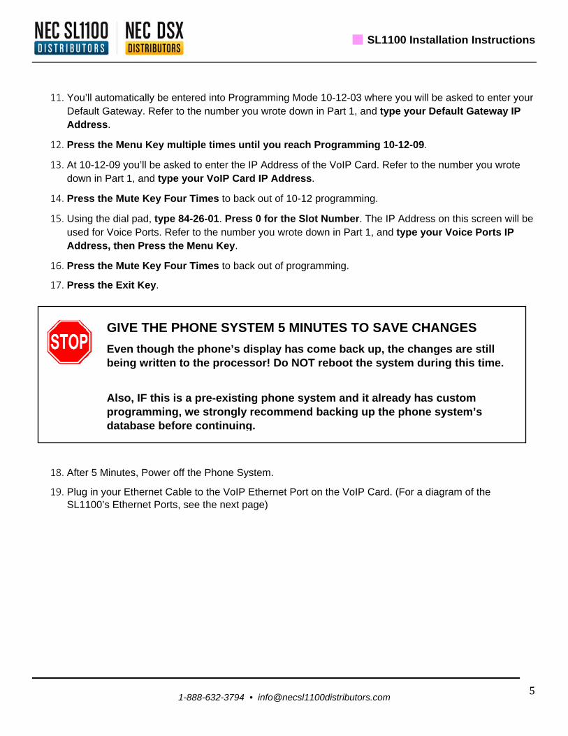
11. You’ll automatically be entered into Programming Mode 10-12-03 where you will be asked to enter your Default Gateway. Refer to the number you wrote down in Part 1, and type your Default Gateway IP Address.
12. Press the Menu Key multiple times until you reach Programming 10-12-09.
13. At 10-12-09 you’ll be asked to enter the IP Address of the VoIP Card. Refer to the number you wrote down in Part 1, and type your VoIP Card IP Address.
14. Press the Mute Key Four Times to back out of 10-12 programming.
15. Using the dial pad, type 84-26-01. Press 0 for the Slot Number. The IP Address on this screen will be used for Voice Ports. Refer to the number you wrote down in Part 1, and type your Voice Ports IP Address, then Press the Menu Key.
16. Press the Mute Key Four Times to back out of programming.
17. Press the Exit Key.
18. After 5 Minutes, Power off the Phone System.
19. Plug in your Ethernet Cable to the VoIP Ethernet Port on the VoIP Card. (For a diagram of the SL1100’s Ethernet Ports, see the next page)
GIVE THE PHONE SYSTEM 5 MINUTES TO SAVE CHANGES
Even though the phone’s display has come back up, the changes are still being written to the processor! Do NOT reboot the system during this time.
Also, IF this is a pre-existing phone system and it already has custom programming, we strongly recommend backing up the phone system’s database before continuing.

SL1100 Installation Instructions
1-888-632-3794 • [email protected] 6
20. Wait 2 Minutes Before Turning the Power Back On.
21. Turn the NEC SL1100 on and wait for the phones and KSU to power up (approx. 3-5 minutes).
22. Go to any phone and press the Menu Key, then 96.
23. Press the Menu Key Again.
24. You will now see that the top IP Address (System) has been set to 0.0.0.0. and the VoIP Card’s IP Address (VoIPDB) has been updated with the address you entered. This is the IP Address you’ll enter in to the PC PRO System Administrator to connect to the system.

SL1100 Installation Instructions
1-888-632-3794 • [email protected] 7
Part 3: Connecting to the SL1100 with the PC PRO System Administrator
Requirements:
PC PRO System Administrator Software (Available in the Downloads Section on necsl1100distributors.com)
1. Open the PC Pro System Administrator on the computer that is connected to the same router as the phone system.
2. Click the Connect Button in the upper left-hand corner.
3. Under Connection Type, Enter the VOIP CARD IP Address you wrote down during Part 1.
4. Enter the User Name: sltech (all lower case with no spaces).
5. Enter the Password: 12345678 (no spaces or other characters).
6. Click connect.
7. IMPORTANT! Once connected, Click the Blue Download Arrow (top left hand portion of the
window).This is an important step, to ensure that you don’t overwrite the phone system’s default settings.
VOIP CARD IP Address from Part 1
sltech
12345678

SL1100 Installation Instructions
1-888-632-3794 • [email protected] 8
8. Click the Start Button to retrieve all the system data that is currently programmed by default.
9. Once the system data has been retrieved and downloaded, click the Close Button.
10. You have now connected, retrieved and downloaded the system data and are ready to make programming changes to your NEC SL1100.

Recording
Voicemail Greetings

Recording Voicemail Greetings
1-888-632-3794 • [email protected] 1
Recording Mailbox Greetings Using an Optional Voice Mail Card
**NOTE** The below instructions are only for customers who purchased an InMail Voice Mail Card. Recording an Automated Attendant (Instruction Menu Greeting) Message 001 through 032
1. From the default extension (101) press the “soft key” under the VM display on the LCD screen
2. Wait for it to answer
3. Dial “SA” [72] to reach the System Administrator options
4. Dial “I” [4] to select the Instruction Menus option
Our default is 001 for a Day greeting... and 002 for a Night greeting. (It could also be from 001 to 032 depending on programming)
5. When prompted, enter the Call Routing Mailbox number 001 through 032
6. Press “L” [5] to listen to the current Instruction Menu (if any)
7. Press “R” [7] to record a new Instruction Menu
8. Record message (i.e. “Thank you for calling ABC Co. if you know your party’s extension...”)
9. Press “L” [5] to listen to what you’ve just recorded
10. If you’re happy with your greeting, hang-up
11. If not, press “R” [7] (Record Again)
Recording Virtual Extension Greetings
Recording Virtual Extension Greetings 250 through 265
From any extension:
1. Lift the handset
2. Dial “3999”
3. You will hear “please enter the mailbox number”
4. Dial the Department Group Number (i.e. 250 through 265)
5. Dial “G” [4] (Greeting)
6. Dial “1” (Greeting 1)
7. Dial “R” [7] to record
8. Dial “L” [5] to listen
9. Hang up to exit

Recording Voicemail Greetings
1-888-632-3794 • [email protected] 2
Recording a Personal Mailbox Greeting
From your extension:
1. Press the “soft key” under the VM display on the LCD screen
2. Lift the handset
3. Dial “G” [4] (Greeting)
4. Dial “1” (Greeting 1)
5. Dial “R” [7] to record (i.e. “Hi this is Tina I’m on my phone or away from my desk…”)
6. Dial “L” [5] to listen
7. Hang up to exit
Recording your Mailbox Name and Extension
From your extension:
1. Press the “soft key” under the VM display on the LCD screen
2. Lift the handset
3. Dial “RN” [76] (Record Name)
4. Dial “R” [7] to record (i.e. “Tina Smith, extension 101”)
5. Dial “L” [5] to listen
6. Hang up to exit
How to Check Mailbox Messages from Outside your Office
From any outside phone
1. Dial your office
2. Wait for your office main greeting to answer
3. Dial Pound Key [#] plus your extension number (i.e. #101 for mailbox 101)
4. Or Dial Pound Key [#] plus your virtual extension number (i.e. #250-265 when applicable)
5. You’re now at your mailbox
6. Listen and follow the mailbox direction prompts
7. Hang up to exit