Embed Size (px)
DESCRIPTION
Welding of Carbon Steels
Citation preview

GAS METAL ARC WELDING OF
CARBON STEEL
1 Introduction 1
2 Base Metals 2
A. Alloying ElementsB. Carbon SteelsC. Alloy Steels
3 Electrical Characteristics 8
A. Power Supply BasicsB. Constant Voltage Power
Supply ControlsC. Electrical Stick OutD. Constant Voltage Power
Supply Characteristics1. Slope2. Inductance3. Heat Input
4 Shielding Gases 14
A. Shielding Gas FunctionsB. Flow RatesC. Gas Losses
5 Electrodes 21
A. Alloying AdditionsB. 1. Solid Wire Designations
and ChemistryB. 2. Metal-Cored Wire
Designations and ChemistryC. Flux-Cored “Tubular” Wire
DesignationsD. Slag and Gas FormationE. Solidification of the Weld Puddle
6 Metal Transfer 26
A. Short-ArcB. Globular TransferC. Spray TransferD. Pulsed Spray Transfer
7 Welding High Strength Steels 33
A. Select the Proper Filler MetalB. Minimize Hydrogen
ContaminationC. Control Heat InputD. Use the Correct
Technique
8 Technique and Equipment 40
Set-UpA. Torch AngleB. Feed Roll TensionC. BurnbackD. Arc and Puddle PositionE. Vertical Down WeldingF. GapsG. Crater FillingH. Arc Starting
9 Weld Discontinuities 45
and ProblemsA. Lack of FusionB. PorosityC. Burn-ThroughD. UndercutE. SpatterF. Cracking
10 Conclusion 50
T A B L E O F C O N T E N T S
Section Topic Page Section Topic Page

1
S E C T I O N 1
Introduction
1
Figure 1 –
Breakdown of
welding costs
This training program was written to give
you a better understanding of the MIG
welding process. MIG is an acronym for
Metal Inert Gas, which is not technically
correct for steels, because shielding gases
for steels contain an active gas such as
oxygen or carbon dioxide. The correct
term according to the American Welding
Society (AWS) is Gas Metal Arc Welding
(GMAW). We will use the correct termi-
nology as defined by the AWS and also
explain the slang used so that you will be
familiar with all the terms applicable to
this process.
As you learn more about GMAW, it will
become apparent that this is a sophisti-
cated process. Welders that have used
“stick” welding (Shielded Metal Arc
Welding or SMAW) are sometimes of the
opinion that the GMAW process is sim-
pler; but to deposit a high quality bead
requires as much knowledge, or probably
more, than the SMAW process. The reason
for this is the number of variables that
affect the arc and the degree of control the
operator has over those variables.
The purpose of this manual is to make you
a better welder by increasing your knowl-
edge of how the GMAW process works. A
more knowledgeable welder can be more
productive by working smarter, not harder.
Figure 1 shows why your company is
interested in your education. Your labor
and overhead account for about 85% of
the cost of depositing weld metal. Any
knowledge you gain from this course not
only helps you, but also helps to make
your company more competitive in a very
tough marketplace. If you should have any
question in the future that this manual or
your supervisor cannot answer, please free
to have him contact your Praxair regional
engineering staff for further assistance.
▲
Wire10%
Overheadand Labor85%
Gas5.0%

The two main categories of steel fabricated
today are carbon and alloy steels. Carbon
steels basically contain carbon and manga-
nese. Alloy steels contain carbon, manga-
nese, and a variety of other elements to
give the base metal the required proper-
ties. Alloy steels cover a wide range of
materials, such as the stainless and tool
steels.
As weight becomes an issue in the trans-
portation industry, there has been a sub-
stitution of high strength low alloy steels
(HSLA) in applications that previously
used carbon steels. The higher tensile and
yield strengths allow the cross-sectional
area weight of the structural members to
be reduced. The resulting weight reduction
allows better fuel economy and a stiffer
body in the case of automobiles, or an
increase in payload in the case of heavy
trucks. Stainless and tool steels are two
more familiar categories of alloy steels.
This manual will concentrate on the low
alloys such as the “construction steels”,
(A514, for example, referred to by USX as
their T1 alloys). In order to understand
alloy steels, it helps to understand a little
bit about the metallurgy involved with the
elements added to increase the strength of
these materials.
Metals are crystals, which mean that the
atoms are arranged in an ordered matrix.
An easy way to visualize a metal is to think
of layers of balls with each ball in the layer
touching its four neighbors (see figure 2).
The balls represent the iron atoms of the
metal. Carbon atoms are much smaller2
S E C T I O N 2
Base Metals
2
▲
than the iron atoms, and they fit into the
open areas between the iron atoms. In
carbon steel, manganese is the other
alloying element. In the matrix, a small
portion of the iron atoms is replaced by
manganese atoms. The layers above and
below the first layer are arranged identi-
cally, except that they are shifted on a
45 degree angle to fall into the areas where
the first layer of balls intersect. Now each
ball in the second layer is touching four
balls in its layer and four balls in the layers
directly above and below it. The orderly
manner in which metals are arranged in
crystals is one of the reasons that they are
so strong. When a metal yields, or deforms
plastically, the planes of atoms slip in
relation to the adjacent planes and at the
grain boundaries. The only single crystal
materials used today are for turbine
blades. They are extremely strong due to
the orderliness of the matrix. They are also
extremely expensive to make.
Figure 2 – Iron body centered
Cubic Unit Cell
Unit cell(9 iron atoms)

The steels that are used in fabrication are
actually made up of grains or groups of
crystals. During welding grains begin to
grow into the molten puddle from the solid
base metal at the edge of the weld. Each
grain continues to grow until it meets
another grain. The area where they meet is
called a grain boundary. In the steels of
most interest, a lot of the “slip” or shifting
of atoms, occurs at these grain boundaries.
Because of grain boundaries, the actual
strength of these steels is typically 25% to
50% of the theoretical strength of a single
crystal of iron.
When carbon is added to a steel, the
strength of the steel goes up dramatically.
The carbon forms a compound called iron
carbide (Fe3C). The size of the iron carbide
molecule (a molecule is a combination of
atoms held together to form a compound)
is considerably larger than the surrounding
iron atoms. When the atomic layers begin
to slip, the larger carbide molecule resists
this slip by “pinning” the layers together
due to their difference in size. There is a
number of other carbide forming elements
that work in a similar manner to strength-
en alloy steels.
The following section lists some of the
elements that are added to steel to yield
the desired properties.
Carbon
As mentioned previously, carbon in steel
forms iron carbide (Fe3C) in the matrix.
The larger size of the carbide compound
pins the layers within the metal matrix and
makes it much more difficult for the mater-
ial to yield. This raises the tensile, yield
strength, and hardness of the steel consid-
erably.
Silicon
Silicon is added mainly as a deoxidizer. It
combines with oxygen to form SiO2. This
silicon dioxide, (also known as glass), floats
to the surface of the weld puddle in com-
bination with manganese oxide to form the
brown slag islands seen in the weld surface.
Silicon can also be added as an alloying
element; this is very beneficial in electrical
steels used in transformers.
Manganese
Manganese is used in small amounts in
most steels to deoxidize, desulfurize, and
improve material properties. The manga-
nese reacts with oxygen and forms manga-
▲
A.AlloyingElements
nese oxide (MnO). The manganese also
combines with sulfur to form manganese
sulfide (MnS) (these are sometimes known
as “stringers” and can cause welding
problems in certain steels). The reason
sulfur is detrimental is that it solidifies at
a low temperature. The liquid sulfur is
carried to the grain boundaries and
reduces the strength of the weld. Any
manganese remaining after formation of
MnO and MnS will form manganese
carbide (Mn3C) which strengthens and
toughens the matrix. A special category
of steel containing greater than 10%
manganese, are called “Hadfield steels”
after the metallurgist that discovered them.
Hadfield steels harden very quickly to
high hardness levels. They are also very
abrasion resistant. The most common
application of these materials is in railroad
crossings or “frogs”. Hadfield steels are
also used in rock crushers, dredging pumps,
and dippers for power shovels.
3

4
Copper
Copper is added in very small amounts to
increase the hardness of the steel. Copper
can also be added to improve the corrosion
resistance of weathering steels such as
“Cor-Ten”. These materials can be seen in
the unpainted condition on bridges, guard
rails, and light poles. The copper aids in the
formation of a very tight oxide that is not
as prone to flaking as carbon/manganese
steel; this slows the corrosion rate of the
material.
Molybdenum
Molybdenum is another carbide forming
element, and is added to most alloy steels
from .5% to 1.5%. Molybdenum improves
yield strength and resistance to high
temperature creep (deformation due to
high temperature and stress). It also helps
to maintain the strength of the steel after it
undergoes stress relief. Molybdenum is
added to stainless steels to reduce pitting
(highly localized corrosion) in corrosive
environments.
Chromium
Chromium is added to increase the
strength, wear resistance, heat resistance,
corrosion resistance, and hardness of steel.
Chromium is also a carbide former, and
forms chromium carbide (Cr3C). In steels,
chromium can also form complex carbides,
Fe2CrC and Cr2FeC.
Bearing steels typically contain about
1% carbon and 1.5% chromium. When
chromium levels rise to about 4%, and
tungsten and molybdenum are added, tool
steels are the result. These materials are
made into the high speed cutting tools
used in machining. Increasing the chro-
mium level above 12-13% causes the
material to resist corrosion; these materials
are known as stainless steels. In chrome
plating, a very thin, tight layer of chro-
mium oxide is formed that resists further
oxidation. As the layer grows in thickness,
the color begins to change to a straw color,
and then to blue. This “bluing” can be seen
on motorcycle exhaust pipes.
Nickel
While nickel does not form any carbide in
a steel matrix, hardenability, ductility and
toughness are all improved when nickel is
added. Nickel is added to austenitic stain-
less steels (300 series) in concentrations of
7-35%. Nickel is also an important element
found in the materials used for storage
of cryogenic fluids. An alloy containing
9% nickel is used to fabricate the inner
vessel in liquid nitrogen, argon, and
oxygen tanks.
Boron
Boron is added in very small amounts to
increase the hardenability of steels. The
amount added is typically below .01%.
King pins, used on semi-trailers, are made
from boron-containing steels.
Vanadium
Vanadium is a strong carbide former, and
increases the hardenability of the steel.
Vanadium is expensive, so it is usually
used in percentages of less than .2%.
This element reduces the grain size and
increases the toughness of the material.
Vanadium steels are used to make axles,
connecting rods, hand tools, and engine
crankshafts.
5
Titanium
Titanium is a strong carbide former that
will also form oxides and nitrides. A large
use of titanium is to stabilize certain
grades of the stainless steels. Titanium
combines with any carbon in the matrix to
form carbides before chromium carbide
precipitation can occur. When chromium
forms carbides, the corrosion resistance of
the material will deteriorate. Titanium also
helps to reduce grain growth in high
strength steels, improving strength and
toughness.
Phosphorus
Phosphorus is generally considered an
impurity in steels; a maximum percentage
is generally listed. Phosphorus tends to
segregate forcing carbon into the sur-
rounding matrix. This can lead to brittle
materials.
Sulfur
Sulfur, also considered an impurity like
phosphorus, is usually specified as a maxi-
mum allowable concentration. Sulfur in
the puddle moves to the grain boundaries
of the solidifying weld metal because of its
low melting temperature. This segregation
in the grain boundaries reduces the
strength of the material. Manganese is
added to prevent this as it combines with
the sulfur (Mn + S = MnS) before it can
react with iron. Certain steels called free
machining steels, contain up to .3% sulfur;
these alloys are difficult to weld and have
poor strength characteristics.
With this greater understanding of the
alloys that are added to steel, let’s look at
carbon and alloy steels.

▲
B.CarbonSteels
Carbon steels are categorized as low,
medium, and high carbon. The main
alloying elements are carbon and manga-
nese. Typical products made of these
three categories of materials are:
Low Carbon Steel 1. Auto frames and bodies
(.005 - .3 C) 2. Auto and truck wheels
3. Structural shapes
(I-beams, channel, angle)
Medium Carbon Steel 1. Machine parts, pins
(.3 - .6 C) 2. Tools
High Carbon Steel 1. Railroad rail
(.6 - 1.0 C) 2. Dies
3. Springs
Carbon is a very powerful alloying element
because it forms iron carbide (Fe3C).
Manganese also forms carbides, but has
much less of an effect on strength and
hardness. The following chart shows two
carbon steels from the low, medium, and
high carbon groups. Notice that the only
real change in most of the alloys is in
carbon content. At the right of the chart
notice that the tensile strength rises rapidly
as the carbon level is increased with little
or no change in the manganese level.
SAE/AISI Carbon Manganese P (max) S (max) Tensile
1008 .08 max .25 - .40 .04 .05 43,000
1018 .14 - .21 .6 - .9 .04 .05 58,000
1040 .36 - .45 .6 - .9 .04 .05 76,000
1050 .47 - .55 .6 - .9 .04 .05 90,000
1070 .64 - .76 .6 - .9 .04 .05 102,000
1090 .89 - 1.4 .6 - .9 .04 .05 122,000
Table 1 –
Chemical
Compositions of
Carbon Steels and
Tensile Strengths
Alloy steels are generally classified by
alloying additions. There are currently
38 different classifications of steels that
are recognized by both organizations that
categorize steels (AISI and SAE). The
following table is included to give a better
understanding of how many steel alloys
there are. The carbon steels, discussed
earlier, are in the first classification. There
are 15 to 20 different carbon steels avail-
able, and there are 38 different classifica-
tions listed. Table 2 gives specification
numbers and alloy classification.
▲
C.AlloySteels
6

Specification Classification
Number
10XX Carbon Steels
11XX Carbon Steels, Resulfurized
12XX Carbon Steels, Resulfurized & Rephosphorized
13XX Manganese Steels
2XXX Nickel Steels
31XX Nickel-Chromium Steels
33XX High Nickel-Chromium Steels
40XX Carbon-Molybdenum Steels
41XX Chromium-Molybdenum Steels
43XX Chromium-Nickel-Molybdenum Steels
46XX Nickel-Molybdenum Steels
48XX High Nickel-Molybdenum Steels
50XX Low Chromium Steels
51XX Chromium Steels
52XXX Carbon-Chromium Steels
61XX Chromium-Vanadium Steels
86XX Low Nickel-Chromium-Molybdenum Steels
92XX Silicon-Manganese Spring Steels
92XX Silicon-Manganese-Chromium Spring Steels
93XX Nickel-Chromium-Molybdenum Steels
98XX Nickel-Chromium-Molybdenum Steels
XXBXX Boron Containing Steels
XXBVXX Boron-Vanadium Containing Steels
WX Water-Hardening Steels
SX Shock-Resisting Steels
OX Oil-Hardening Steels
AX Air-Hardening Steels
DX High Carbon-High Chromium Tool Steels
HXX Hot Work Tool Steels
TX High Speed Tungsten Based Tool Steels
MX High Speed Molybdenum Based Tool Steels
LX Special Purpose Tool Steels
FX Carbon-Tungsten Tool Steels
PX Mold Steels
2XX Chromium-Nickel-Manganese Stainless Steels
3XX Chromium-Nickel Stainless Steels
4XX Chromium-Stainless Steels
5XX Low Chromium Heat Resisting Stainless Steels
Table 2 –
Alloy Steel
Classification and
Specification
Numbers
7

The power supply (or welding machine)
connected to the torch is basically a big
transformer/rectifier. Its purpose is to
take high voltage (440v or 220v) and low
current (20-50 amps/leg) AC power and
transform it to low voltage (16-40v),
high current (80-500 amp) DC power.
To change AC to DC, a device called a
rectifier is used. Direct current provides a
much more stable arc. Most GMAW power
supplies are set-up using a reverse polarity
connection. Reverse polarity is designated
as DCEP, which means Direct Current,
Electrode Positive. An easy way to
remember this is:
A.Power SupplyBasics
S E C T I O N 3
Electrical Characteristics
▲
3
Figure 3 –
Typical GMAW
Power Supply
Congress is made of:
SENators And REPresentatives
Straight Electrode Negative
Reverse Electrode Positive
Almost all GMAW power supplies are
constant voltage machines, where Stick
Electrode (SMAW) machines are constant
current.
8
DCLow VoltageHigh Current
ACHigh VoltageLow Current
Work
Reverse Polarity - DCEP (DC - Electrode Positive)Straight Polarity - DCEN (DC - Electrode Negative)
+
–
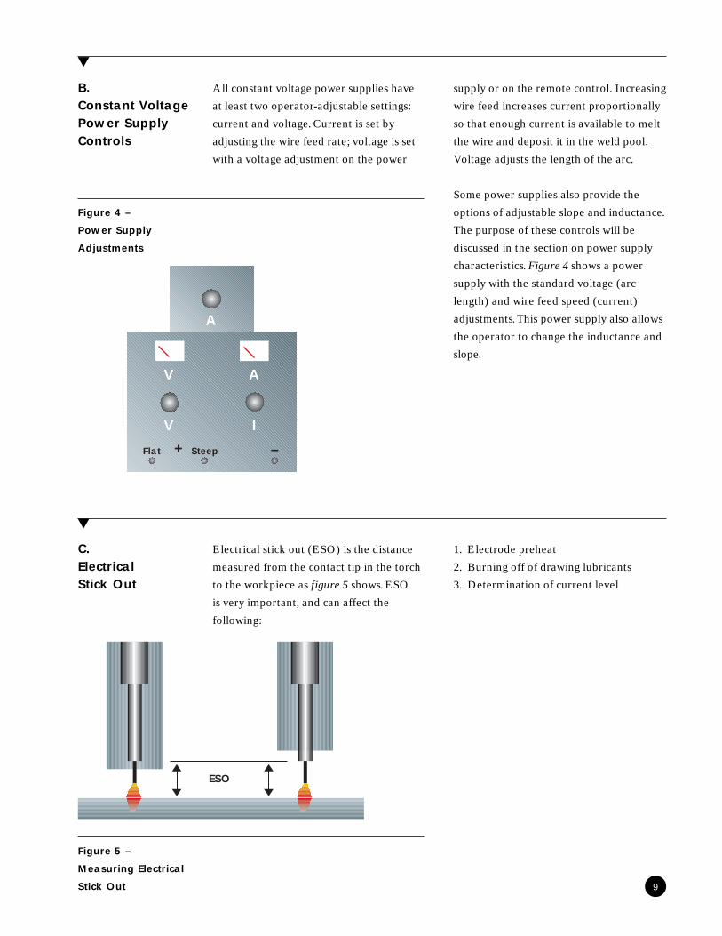
All constant voltage power supplies have
at least two operator-adjustable settings:
current and voltage. Current is set by
adjusting the wire feed rate; voltage is set
with a voltage adjustment on the power
supply or on the remote control. Increasing
wire feed increases current proportionally
so that enough current is available to melt
the wire and deposit it in the weld pool.
Voltage adjusts the length of the arc.
Some power supplies also provide the
options of adjustable slope and inductance.
The purpose of these controls will be
discussed in the section on power supply
characteristics. Figure 4 shows a power
supply with the standard voltage (arc
length) and wire feed speed (current)
adjustments. This power supply also allows
the operator to change the inductance and
slope.
B.Constant VoltagePower SupplyControls
▲
Figure 4 –
Power Supply
Adjustments
Electrical stick out (ESO) is the distance
measured from the contact tip in the torch
to the workpiece as figure 5 shows. ESO
is very important, and can affect the
following:
1. Electrode preheat
2. Burning off of drawing lubricants
3. Determination of current level
▲
9
Figure 5 –
Measuring Electrical
Stick Out
C.ElectricalStick Out
V
V
A
I
A
+ –Flat Steep
ESO

The wire in the GMAW process is called
an electrode because it conducts electricity.
The current is transferred to the wire in
the contact tip. The energy resulting from
the welding current is distributed to two
different places in the welding circuit;
(1) resistance heating of the electrode,
and (2) penetration into the base metal as
figure 6 shows. The electrode acts like the
elements in a home toaster. As current
passes through it, resistance heating occurs
and its temperature rises. The increased
temperature burns off drawing lubricants
used in the manufacturing of the wire. The
temperature rise also helps make it easier
to melt the electrode. This is the reason
that deposition rate increases as ESO
increases. As ESO increases, current is
decreased. This also helps to keep the
contact tip cooler at higher deposition
rates. This is a big help in controlling
penetration, because as current increases,
so does the depth of penetration. By using
a slightly longer stickout, more weld metal
can be deposited without burning through
thinner parts. Increasing ESO makes the
arc harder to start because less current is
available at the arc due to resistance heat-
ing. As more resistance is put into the
welding circuit (increased ESO), the effec-
tive slope of the system is also increased.
This also tends to reduce the short-circuit
current.
ESO also affects shielding gas coverage. As
the distance increases from the contact tip
to the work (also called TWD – tip to work
distance), you reach a point where the
shielding gas cannot effectively blanket the
molten weld puddle. This will be covered
in more detail in the shielding gas section.
Figure 6 –
Current
Distribution
10
Current from the power supplyis distributed to:
1. Resistance heating of the electrode (ESO dependent)2. Penetration into base metal

D.Constant VoltagePower SupplyCharacteristics
1. Slope
The characteristics of a power supply are
determined by the components used in its
design. The performance of a typical mach-
ine is described by a graph such as figure 7.
Most constant voltage power supplies
without slope adjustment are factory
preset at about 2 volts/100 amps
(flat slope).
This means that for each increase of
100 amps, the power supply will produce
2 volts less at the same voltage setting.
The lower slope line is 6 volts/100 amps,
and is about the maximum slope seen in
a constant voltage power supply (steep
slope). A few machines are still available
with continuously adjustable slope; others
have external or internal taps to switch
between slopes. Increasing the slope of a
power supply to control short-arc welding
at low currents is necessary because the
short-circuit current is limited. This
reduces the tendency to burn-through on
thinner materials and decreases spatter on
arc starts. This will be explained further in
the section on metal transfer.
Figure 8 shows a typical 2 volt/100 amp
slope power supply characteristic curve.
A review of this graph helps to explain
why the arc changes during welding. As
an example, select a welding condition of
27 volts and 250 amps. As welding contin-
ues, if the stickout (ESO) is reduced the
welding conditions change. As that change
is made, the spatter level begins to in-
crease. As ESO is decreased, less current
goes into preheating the wire and more
goes into the arc. Suppose the current
increases 50 amps, which is easily done
with a small torch movement of about 1/4".
This moves the operating point to the
second point in figure 8; here the voltage
decreases to 26v while the current in-
creases to 300 amps. This voltage is at the
minimum for spray transfer; this would
account for the slight increase in spatter
that is observed. This will be explained in
more detail in Section 6.
11▲
Figure 7 -
Power Supply
Characteristics
Curves
Figure 8 –
The Effect of Slope on
Current and Voltage
100 150 200 250 300 350
32
30
28
26
24
22
20
18
Current (Amps)
Volts CC-Drooping
CV-Flat Slope (2V/100A)CV-Steep Slope (6V/100A)
225 275250 300
22
21
20
19
18
17
Current (Amps)
Volts
Flat Slope2V/100A

Measuring Actual Welding Voltage
Measuring actual welding voltage is a use-
ful way to be certain that the condition is
within the range specified by the welding
procedure. Hard starts can result from
bad connections in the welding circuit.
The voltage drop due to bad connections
increases the slope of the system, and
reduces the available short-circuit current.
Comparing the voltage at the power
supply terminals and between the feeder
and the work (figure 9) will give the
voltage drop due to resistance. It can
12
measure as high as 5 volts which makes
starting the arc difficult.
2. Inductance
Inductance is an adjustment that is provid-
ed more frequently than slope on CV
power supplies. Inductance is another
method for controlling the arc. This is done
by controlling the rate at which the weld-
ing current reaches the setting selected.
Figure 10 shows a plot of inductance vs.
time. The top curve shows what happens
with no additional inductance and the
current rises as quickly as the power sup-
ply will allow it to rise. This can result in
very hot starts or even in the wire explod-
ing at these very high current levels.
Inductance should be kept low for spray
transfer. This produces better arc starting
and more stable arc at high currents. High
inductance settings can make it hard to
initiate the arc because it limits the maxi-
mum short circuit current available for
this purpose.
Referring again to figure 7, as the elec-
trode first touches the work to strike an
arc, the voltage falls from open circuit
voltage (40-50v) to 0 arc volts. At 0 volts
(no arc length or a dead short), the power
supply produces the maximum short-
circuit current. For a machine rated at
450 amps (at 100% duty cycle) this might
be 550-600 amps. A 600 amp machine
might produce up to 800 amps during this
initial start. This is more than enough
current to explode the wire and make the
arc difficult to start. If the arc start is too
hot, either the slope can be increased or
inductance added to reduce the current at
arc initiation. Inductance can be beneficial
when welding with low current short-arc,
as it makes the puddle more fluid and
allows it to better wet the base material.
Figure 9 –
Measuring Actual
Welding Voltage
Figure 10 –
The Effect of Increasing Inductance
V
V
A
I
A
+ –Flat Steep
–+
27.5
Volt Meter
Work
Connect to+ terminal onfeeder and workpiece and readwhile welding
Least Inductance
More Inductance
Most Inductance
Time (milliseconds)
600
500
400
300Curr
ent
(am
ps)

3. Heat Input
A useful formula often used by welding
engineers is the heat input equation. If
you have been welding high strength or
corrosion resistant alloys, you may already
be familiar with this formula. It allows you
to calculate the amount of heat delivered
to the workpiece.
The formula is:
Heat input is measured in units of energy/
unit of length (joules/inch). A joule is a
unit of energy equal to 1 watt of energy
into the workpiece per second. While a
joule is not a familiar unit of measurement,
there are a lot of uses for the heat input
formula itself.
For example, suppose that welding is done
at the second condition used as an example
in figure 8. That condition was 300 amps
and 26 volts. For this example, say the
travel speed is 10 in/min. This works out
to a heat input of 46,800 joules/in. If we
know that the welding involves bridging
a gap, ESO can be increased to reduce
current and increase voltage while reach-
ing the first condition indicated. That was
250 amps and 27 volts, still at 10 in/min.
The heat input is now 40,500 joules/in. By
increasing ESO (stickout), heat input has
been reduced by almost 15%.
The heat input formula is also used for
when welding high alloy materials, but it
also helps in understanding the uses of the
power supply characteristic curve.
The heat input formula can assist in pre-
paring welding procedures where similar
material thicknesses and joint configura-
tions are welded. After determining the
range of heat inputs that produce an
acceptable weld, the range of heat inputs
can be calculated. This is really helpful in
increasing speeds for robotic welding. The
required travel speed can be calculated as
wire feed speed (current) and voltage are
increased. The formula is also helpful in
controlling distortion. Conditions that put
less energy into the metal can be calcu-
lated, which reduces distortion.
Heat Input = Amps X Volts X 60
Travel Speed (in/min)
13

At high temperature, all metals commonly
used for fabrication will oxidize in the
presence of the atmosphere. Every welding
process provides shielding from the atmos-
phere by some method. When welding
steels, we want to exclude oxygen, nitro-
gen, and moisture from the area above
the molten puddle.
In the Oxy-fuel process, the weld pool
is shielded from the atmosphere by the
combustion by-products of carbon monox-
ide (CO) and carbon dioxide (CO2). In
stick welding (SMAW), CO and CO2 are
also the shielding gases. The 60XX type of
electrode uses a cellulosic coating, which
has very high moisture content. The
moisture produces oxygen and hydrogen in
the arc environment.
Submerged-arc welding shields the puddle
by a different method. As the puddle
progresses, the intense heat melts the flux
in the joint area; this forms a slag that
covers the weld and excludes the
atmosphere.
GMAW (MIG) and GTAW (TIG) are
both gas shielded processes in which the
shielding gas is provided from an outside
source. No fluxing agents are included in
the filler metal of solid wires.
S E C T I O N 4
Shielding Gases
4
▲
14
▲
A.Shielding GasFunctions
For the purpose of this discussion the
GMAW process will be emphasized
because it constitutes the greatest portion
of welding done in industry. A good
portion of this information is applicable
to GTAW too.
The major functions of a shielding
gas are to:
1. Protect the puddle from the atmosphere
2. Provide arc plasma
3. Provide oxygen for wetting
(ferrous alloys)
4. Control type of metal transfer
5. Affect arc stability
6. Control welding costs.
As was mentioned earlier, the atmosphere
must be displaced while the puddle is
cooling or oxidation will occur rapidly.
This appears as a gray surface on the weld
bead. One cause of porosity is the result of
poor shielding when atmospheric oxygen
combines with carbon in the puddle. As
the weld metal cools, porosity occurs as
this carbon monoxide escapes from the
center of the bead. If air is aspirated into
the shielding gas line through a leak,
nitrogen and moisture will also contami-
nate the shielding gas. Nitrogen, while very
soluble in the puddle at high temperatures,
will cause porosity as it escapes during
cooling of the weld bead.

The shielding gas also provides a portion
of the arc plasma, which transfers the
welding current across the gap between
the electrode and the work as figure 11
shows. This is accomplished by “ionizing”
the gas, which frees electrons to transfer
the current from the work to the electrode.
Metallic and argon ions (atoms stripped of
an electron) transfer the positive charge
across the arc. This explains in part why
the arc becomes very unstable when a
torch is hooked up using straight polarity
(DCEN) rather than reverse polarity
(DCEP). In DCEN, the positive current is
trying to remove iron atoms from the plate,
which are much harder to melt than a
small diameter electrode.
In steels (carbon and stainless), oxygen
stabilizes the arc and reduces the surface
tension of the weld metal. Oxygen is
obtained from direct additions of oxygen
or carbon dioxide to the shielding gas.
Surface tension, the force that causes
water to bead up on a waxed car surface,
is not desirable when depositing a weld
bead. If pure argon is used instead of a
mixed gas, the bead does not wet out and
appears as though it is sitting on top of the
part surface (convex bead).
Figure 12 shows the basic gases used in
shielding GMAW. The ionization potential
is the amount of energy (in electron volts)
required to establish an arc. The use of a
helium rich gas such as Praxair’s HeliStar™
A-1025 blend (for short-arc welding of
stainless steel), requires 3-5 volts more
than an Ar/CO2 mixture at the same
current. The shielding gas used also has a
pronounced effect on the type of metal
transfer obtained.
Figure 11 –
Transfer of Current
Across the Arc
Plasma
Figure 12 –
Gases Used for
GMAW Shielding
15
Gas Characteristic IonizationPotential (eV)
Ar Totally Inert (Cool) 15.759
He Totally Inert (Hot) 24.587
O2 Highly Oxidizing 13.618
CO2 Oxidizing (Dissociates 13.769
H2 Highly Reducing 13.598
–
+
DCEP
e–Fe+
Ar+

There is a “best gas” for almost every
application, but there may be 2 or 3 gases
that will do a very reasonable job. Gases
are selected on the basis of performance,
availability, cost, and many other variables.
Further discussion of gases and metal
transfer is found in section 6.
Stability of the arc plasma is another factor
influenced by the shielding gas. Pure argon
provides a stable arc, and is used when
welding reactive metals such as aluminum.
Argon/oxygen mixtures are also very
stable, and are used in steel welding
applications. Pure carbon dioxide provides
a less stable arc plasma, but its additions
to argon can be very beneficial where
depth and width of penetration need
to be controlled. Some shielding gases
also use additions of oxygen and carbon
dioxide in one mixture (Praxair's Stargon™
gas blend).
Once the shielding gas is selected, it is
critical to make sure that the flow rate is
within certain limits. For low current short-
arc applications, 25-35 scfh (standard cubic
feet per hour) is adequate if ESO is held
from 3/8" to 1/2". For high current short-
arc and the spray transfer mode, flow rates
need to be increased to the 35-45 scfh
range. Figure 13 shows the best way to
measure the flow rate using a torch
flowmeter.
Regulator-flowmeters can vary the inlet
pressure to the flowmeter. As inlet pres-
sure falls when a cylinder gets low, the flow
rate is actually skewed to a higher reading.
For example, a regulator-flowmeter,
installed in a low pressure line (20 psig),
showed a flow reading of 70+ scfh, but
the actual flow rate was 15 scfh. The
regulator had reduced the pressure in the
flowmeter to about 5 psig instead of the
correct design pressure of 50 psig. Flow
rates must be kept in a controlled range so
that the shielding gas column does not
become unstable and mixes with air at
both low and high flow rates or when
forced to flow past an obstruction in the
nozzle such as spatter. This type of flow is
called turbulent (non-axial flow).
Figure 13 –
Measuring Actual
Flow Rate
16
▲
B.Flow Rates
706050403020100•
30 - 70 scfhmeasuredat the nozzle

Testing has shown that, the shielding gas
column stays in laminar flow from 30 scfh
up to about 70 scfh with a 400 amp gun
(using a 5/8" diameter nozzle). Above
70 scfh, the flow becomes turbulent and
mixes with air. A cigarette in an ashtray
can illustrate the difference between
laminar and turbulent flow. The smoke
initially leaves the tip, in a tight orderly
laminar flow. A few inches above, the flow
becomes turbulent and the smoke mixes
with the air rapidly as shown in figure 14.
This same thing happens with a column of
shielding gas. The erratic quality of the
shielding can provide a weld that looks
satisfactory, but can contain subsurface
(honeycomb) porosity. As deposition
rates increase, a 35-45 scfh flow rate is still
satisfactory unless there are breezes or
drafts. In high deposition MIG welding,
a .045 wire, can be run at 1300 ipm
(35 lb/hr) at 50-60 scfh with no problems.
Fans and drafts will displace a shielding
gas, and may require increasing flow rates
to 50-70 scfh. Reducing cup-to-work
distance can also improve shielding.
Figure 14 –
Laminar and
Turbulent Flow
▲
C.Gas Losses
Loss of shielding can cause problems in
GMAW. Inadequate gas coverage can
result in an oxidized surface or porosity.
The first step in troubleshooting what you
think may be a gas loss is the use of a torch
flowmeter. This flowmeter fits over the
nozzle on a torch and measures the actual
flow rate of your shielding gas (figure 13).
Compare the actual reading with that of
the station flowmeter (if used). The two
readings should be very close to each
other. If not, there may be some potential
problem areas.
17
Air
Air
LaminarFlow
TurbulentFlow
TurbulentFlow
LaminarFlow

Threaded Connections are notorious for
leaking if not properly sealed. A pipeline
with shielding gas at 50 psi can leak a lot of
expensive gas. It will also allow air to
diffuse in, as figure 15 shows.
If the leak is large enough, no amount of
flow can give a good quality weld. Use a
liquid leak detector to find any leaks.
A few shops use quick disconnects for
their shielding gasses. There are also prime
suspects when investigating leaks. Use a
liquid leak detector solution to check
them. If the flow measurement at the torch
indicates a much lower flow than the
station flowmeter, find the source of the
problem by disconnecting the supply hose
at the wire feeder. Use the torch flow
meter to check the flow out of the hose. If
the flow meter is correct, check if a leaking
fitting or if the o-rings in the back of the
liner have been damaged (figure 16). These
can be easily replaced, and should be
lightly coated with silicone grease to avoid
damaging them during reinstallation.
Another place where shielding gas flow
can be disrupted is in the diffuser. The gas
diffuser is found at the point where the
contact tip is mounted. Its purpose is to
distribute the gas evenly to produce
laminar flow out of the gas nozzle. If
spatter builds up on the diffuser, it can
clog it and reduce the gas flow enough to
provide poor shielding. If the diffuser is
only partially blocked, the entire gas flow
may try to exit the holes still open and
create unbalanced turbulent flow. This in
itself will aspirate air into the shielding gas
column and may once again, cause
porosity.
Figure 15 –
Back Diffusion Allows
Air to Leak into a
Pressurized Line
18
Figure 16 –
O-Rings Seal the Gas
Ports at the Feeder
Hose Wall
Hose Wall
ProcessGas
Air
N2, O2, H2O
CL
Wall
Wall
Distance
O2 C
oncenVelocity
N2, O2, H2O
Lube O-Ring with siliconegrease before installing

Holding the torch at too small an angle can
also create a venturi effect between the
plate and the nozzle. This will also con-
taminate the shielding gas stream with air
and cause porosity (figure 17).
Some welders clean spatter from nozzles
by lightly tapping the gas cup against
something which knocks the spatter out.
This can create a problem by eventually
causing the cable to gooseneck connection
to loosen. When this happens, it is possible
to lose your gas coverage in the torch
handle and aspirate air into the shielding
gas stream.
One final thing to check is incorrect inlet
pressure to the flowmeter. All flowmeters
are calibrated for one specific inlet
pressure, and the actual flow reading will
be incorrect if the inlet pressure does not
match the calibration pressure. Figure 18
shows what happens when a 20 psig
calibrated flowmeter is attached to a
50 psig line. The actual flow is 26% higher
than indicated on the flowmeter. The
easiest way to check this is by using a
torch flowmeter, because it is calibrated
for atmospheric pressure at the outlet.
Penetration Patterns
The penetration pattern of a weld can be
examined by cutting and etching the weld
as shown in figure 19. To examine a weld,
cut through it at 90 to the face. The
sample is easiest to prepare when a saw is
used. The cut face is then sanded with
progressively finer sandpaper until a 320
grit paper is reached. An etchant reveals
the penetration pattern. For steels, there
are many different etchants available. For
macro-etching, a mixture of 10% nitric
acid in methanol works well. This etchant
is called nital-10%.
Figure 17 –
Air Aspirated by the
Venturi Effect can
Contaminate the
Shielding Gas
19
Figure 18 –
Pressure Correction
Formula for Flowmeters
Figure 19 –
Weld Terminology
and Penetration
Measurement
Venturi effect pulls airinto the shielding gas
Example: A flowmeter calibrated at 20 psig on a 50 psig line indicating 40 scfh
ActualFlow Rate
IndicatedFlow Rate
Actual Pressure (psia)
Calibration Pressure (psia)= x
ActualFlow Rate 40 scfh
50 + 14.7
20 + 14.7= x
= 40 x 1.37 = 54.6 scfh
EffectiveThroat
Root
Toe
Face

20
When the etchant is swabbed on the weld
area, the different microstructures react at
different rates. The darkest area will be the
heat-affected zone, or HAZ. This is base
metal that is adjacent to the weld metal.
The HAZ has been heated to near the
melting temperature and then cooled very
rapidly. The cooling is caused by the
quenching effect of the colder base metal.
By measuring from the face of the weld to
the root, we find the effective throat of the
fillet weld as shown in figure 19.
Different gases will change the shape and
depth of the penetration pattern. Oxygen
additions will reduce the diameter of the
plasma, and lead to a deep and narrow
penetration pattern as shown in figure 20.
This is sometimes called “finger-like”
penetration. Additions of carbon dioxide
and helium increase the diameter of the
plasma because of their increased thermal
conductivity. This tends to decrease the
effective throat and broaden the penetra-
tion pattern.
Figure 21 shows the penetration patterns
of tubular (flux-cored or metal cored) and
solid wires at the same power (current
and voltage) level. The tubular wires are
made with a solid sheath and filled with a
powder; most of the current is carried by
the sheath. This increases the diameter of
the plasma, and makes for a less penetrat-
ing or softer arc. Because of the axial metal
transfer characteristics in spray transfer
with solid wire, the penetration pattern is
narrower and deeper than that of a tubular
wire. Because the power of the two arcs is
the same in the example, the areas melted
in the base metal are equal, but different in
shape. In some welding applications where
a solid wire produces burn-through on
thinner parts, a tubular wire may be a good
choice because the larger diameter plasma
spreads the heat over a larger area and
reduces the tendency to burn-through.
Figure 20 –
Different Gases
Provide Different
Penetration Patterns
Figure 21 –
Penetration Patterns
of Solid and Tubular
Wires in Spray
Transfer
C-25 O-5 C-15/C-8
Equal Areas
Solid Tubular

Although a welder doesn’t often get the
chance to select a filler material, this
section is included for information.
Knowing how wires are alloyed and why,
can sometimes be helpful when a problem
arises. We will concentrate on a few carbon
steel wires, because they are used in the
biggest portion of GMAW welding.
S E C T I O N 5
Electrodes
5
▲
A.AlloyingAdditions
The list shown in figure 22 outlines the
elements added to steel and the reasons
for their addition. These are the same
alloying elements that are added to the
base metals, proportions differ slightly for
filler metals.
1. Carbon – The addition of carbon to iron
has a very strong influence on its proper-
ties. Mild steels, 1010 and 1020 for instance,
have low carbon contents (0.1 and 0.2%
respectively.) Carbon is a very potent
strengthener, and when added above about
0.3%, requires special welding procedures
to keep the material from cracking
(preheat, interpass and post heat, etc.)
Most common wires are low in carbon
content.
2. Manganese – This element is added for
three reasons: (1) Deoxidation. Manganese
combines with oxygen in the weld metal
before the carbon does so there is little or
no oxidation of carbon in the weld puddle
to produce carbon monoxide (and cause
porosity. (2) Desulfurization. Manganese
combines with sulfur to form manganese
sulfides before the sulfur can segregate to
the grain boundaries and form low melting
point iron sulfides. Iron sulfides can cause
hot cracking in steels. (3) Strengthening.
Manganese remaining after these other
reactions combine with carbon to form
manganese carbides, which strengthen the
weld deposit.
21
Figure 22 –
Steel Alloying
Additions
Figure 23 –
Deoxidation
Reactions
Steel is iron that is alloyed with
Carbon Strength
Manganese Deoxidation & Strength
Silicon Deoxidation
Aluminum Deoxidation
Zirconium Deoxidation
Titanium Deoxidation
Liquids
Gases
Si + 2O -> Si O2Mn + O -> MnO
C + O -> COC + 2O -> CO2

4. Aluminum – The main function of this
element is also deoxidation. It is a very
strong deoxidizer and forms aluminum
oxide (Al2O3). A secondary function is that
of a grain refinement, which produces a
stronger, tougher deposit.
5. Zirconium – This is also a deoxidizer,
and is used in only a few wires.
6. Titanium – This element is also a
deoxidizer in low carbon steels.
3. Silicon – This element is mainly added as
a deoxidizer. Silicon combines vigorously
with oxygen in the weld puddle and forms
a silicon dioxide (see figure 23) slag.
Beach sand is silicon dioxide. When the
silicon combines with the oxygen, heat is
generated because of this oxidation
reaction. This is one reason why a wire
higher in silicon will provide a more fluid
puddle. The brown glassy solid that forms
on the weld deposit is a combination of
silicon dioxide and manganese oxide.
▲
B.1. Solid WireDesignationsand Chemistry
With some understanding of why alloy
additions are made to low carbon wires,
the compositions of some commonly used
wires are more meaningful. Figure 24
shows the American Welding Society
(AWS) nomenclature used for solid wires.
Table 3 shows the chemistries of the
available ER70S- electrodes.
Figure 24 –
AWS Solid Wire
Designation
Table 3 –
ER70S - Wire
Chemistries
AWS Carbon Manganese Silicon Phos. Sulfur Other
Electrode (max) (max)
Class.
ER70S-2 .07 Max .9 - 1.4 .4 - .7 .025 .035 TI,ZR,AL
ER70S-3 .06 - .15 .9 - 1.4 .45 - .7 .025 .035
ER70S-4 .07 - .15 1.0 - 1.5 .65 - .85 .025 .035
ER70S-5 .07 - .19 .9 - 1.4 .3 - .6 .025 .035 AL
ER70S-6 .07 - .15 1.4 - 1.8 .8 - 1.15 .025 .035
ER70S-7 .07 - .15 1.5 - 2.0 .5 - .8 .025 .035
22
ER70S-X
Electrode
70,000 UTS70 - 120 ksi
Chemistry2, 3, 4, 5, 6,7, 8, 9, 10, G
Rod Solid
These wire designations are set by the
AWS, to standardize welding electrodes
and filler metals. The classification system
is based on chemical composition and
strength of the deposited weld metal. A
typical solid wire designation would be
ER70S-3. The E designates a wire can be
used as an electrode, meaning it can carry
current. The second character, R, indicates
that this alloy is available as rod. Rods are
usually the 36" straight lengths and are
used for GTAW (TIG). The third and
fourth characters indicate the minimum
tensile strength of the weld metal in
thousand psi’s. An ER70S-X wire would
have a tensile strength of 70,000 psi. The
fifth character, S, indicates that this is a
solid wire. The number after the dash
indicates the composition classification of
the alloy. These numbers run from 2 to 7
and G. The G classification (stands for
general) indicates a chemistry agreed upon
by the supplier and purchaser.
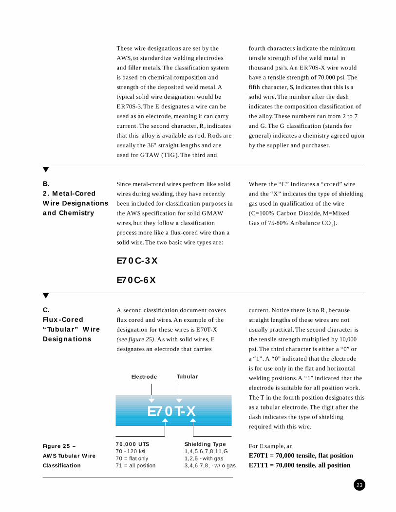
Since metal-cored wires perform like solid
wires during welding, they have recently
been included for classification purposes in
the AWS specification for solid GMAW
wires, but they follow a classification
process more like a flux-cored wire than a
solid wire. The two basic wire types are:
E70C-3X
E70C-6X
▲
B.2. Metal-CoredWire Designationsand Chemistry
Where the “C” Indicates a “cored” wire
and the “X” indicates the type of shielding
gas used in qualification of the wire
(C=100% Carbon Dioxide, M=Mixed
Gas of 75-80% Ar/balance CO2).
23
A second classification document covers
flux cored and wires. An example of the
designation for these wires is E70T-X
(see figure 25). As with solid wires, E
designates an electrode that carries
current. Notice there is no R, because
straight lengths of these wires are not
usually practical. The second character is
the tensile strength multiplied by 10,000
psi. The third character is either a “0” or
a “1”. A “0” indicated that the electrode
is for use only in the flat and horizontal
welding positions. A “1” indicated that the
electrode is suitable for all position work.
The T in the fourth position designates this
as a tubular electrode. The digit after the
dash indicates the type of shielding
required with this wire.
For Example, an
E70T1 = 70,000 tensile, flat positionE71T1 = 70,000 tensile, all position
Figure 25 –
AWS Tubular Wire
Classification
C.Flux-Cored“Tubular” WireDesignations
▲
E70T-X
Electrode
70,000 UTS70 - 120 ksi70 = flat only71 = all position
Shielding Type1,4,5,6,7,8,11,G1,2,5 - with gas3,4,6,7,8, - w/o gas
Tubular

Deoxidation of the weld pool is very
important in metal joining. There are at
least 5 elements added for deoxidation,
each doing a slightly different job. As a
general rule, the rustier or more mill-
scaled a plate is, the more deoxidation
required from the electrode. The shielding
gas is also a source of oxidation. If a rusty
plate is welded with a gas of high oxidation
potential, a cleaner deposit would be
obtained if a change from an S-3 to an S-7,
D.Slag and GasFormation
S-6 or even an S-2 solid electrode is made.
To determine the deoxidation potential of
a flux-cored wire, the manufacturer’s
literature must be consulted. Flux-cored
wires contain increasing amounts of
deoxidizers to remove the oxygen being
deposited in the weld puddle by the
shielding gas and by any mill scale or rust.
Both mill scale and rust are iron oxides
(FeO- mill scale, and Fe2O3) .
Silicon and manganese are oxidized in the
molten weld puddle. Silicon forms silicon
dioxide and manganese forms manganese
oxide. These reactions occur to remove the
oxygen and keep the carbon and iron from
being oxidized. Higher oxidizing potential
gases, such as pure carbon dioxide will
oxidize more of the alloying additions
and produce a deposit of slightly lower
strength and toughness. The oxygen in the
weld puddle will also combine with the
carbon to form carbon monoxide if all
of the manganese and silicon have been
oxidized. Porosity in a weld is usually
caused by the evolution of carbon mon-
oxide. The reactions that occur in the
molten puddle are:
Si + O2 SiO2
2Mn + O2 2MnO2C + O2 2COC + O2 CO2
The SiO2 and the MnO are liquids that
float to the surface of the puddle. Upon
cooling, they are commonly referred to as
slag islands. Higher oxygen contents can
remove much of the silicon and manganese
so that the oxygen will then begin to
combine with carbon. Carbon monoxide
and carbon dioxide result, and most of the
gas formed is carbon monoxide. The gases
will evolve from the molten puddle, but if
cooling is rapid and the gas concentration
is high gas bubbles will be trapped and
create porosity. Nitrogen is also soluble
in the puddle and will cause porosity if
shielding is inadequate.
24
▲
▲▲
▲▲

Figure 26 shows how a weld puddle cools
and solidifies. At the weld puddle to base
metal interface, crystals begin to grow into
the molten weld pool. This is very similar
to the growth of ice crystals on a window
seen in time-lapse photography. The
crystals are called grains, and where they
meet and stop growing is called the grain
boundary. As the metal solidifies, the
solubility of gases decreases greatly. If
there is just slightly more oxygen in the
puddle than manganese and silicon
available for deoxidization (and also
possibly nitrogen), these gases will be
pushed to the centerline as the puddle
freezes. This causes porosity along the
solidification line and is known as
centerline porosity. Larger amounts of
contamination can cause gross porosity in
the weld and lead to the condition shown
in the bottom illustration in figure 26.
As the weld is finished, the cooling rate
at the crater increases because the weld
is losing heat in all directions. This rapid
cooling rate leaves less time for the gases
to leave the puddle, and a hollow gas
cavity can form at the crater.
Calculation of Deposition Rates
A very useful piece of information needed
when calculating the cost of welding is the
deposition rate. The deposition rate is
usually stated in pounds of wire per hour
of weld time. Figure 27 shows the multipli-
ers that can be used to determine deposi-
tion rate for different diameters of solid
wires. The multiplier is a factor that takes
into account the cubic inches of wire per
hour consumed and the density of steel,
to arrive at the rate in pounds per hour.
To calculate the deposition rate of an
.045" diameter wire at 500 ipm wire feed
speed, multiply the 500 ipm times the
.027 multiplier, and determine a rate of
13.5 lbs/hr of arc-on time. To determine the
actual amount of metal deposited, multiply
this weight by the duty cycle (% of an hour
that the arc is actually on) and the deposi-
tion efficiency of the process.
Figure 27 –
Calculating Deposition
Rates for Solid Electrodes
25
Wire Diameter Multiplier
.030 .012
.035 .0163
.045 .027
.052 .0361
.0625 .0521
Example: an .045 wire at 500 ipm
500 ipm x .027 = 13.5 lbs/hour
▲
Figure 26 –
Solidification of
a weld
E.Solidificationof the WeldPuddle
S E C T I O N 6
Metal Transfer
6
▲
An understanding of metal transfer is very
helpful when trying to solve a welding
problem such as “why is there so much
spatter?”, or “how can more penetration
be obtained.” In this section, electrical
characteristics, wires and shielding gases all
come together. There are four major types
of metal transfer that will be discussed.
They are:
1. Short-Arc
2. Globular Transfer
3. Spray Transfer
4. Pulsed Spray Transfer
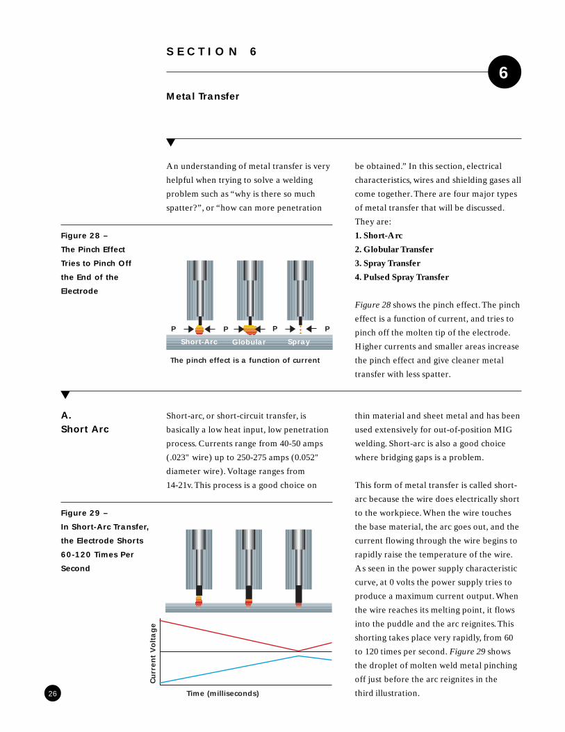
Figure 28 shows the pinch effect. The pinch
effect is a function of current, and tries to
pinch off the molten tip of the electrode.
Higher currents and smaller areas increase
the pinch effect and give cleaner metal
transfer with less spatter.
26
▲
A.Short Arc
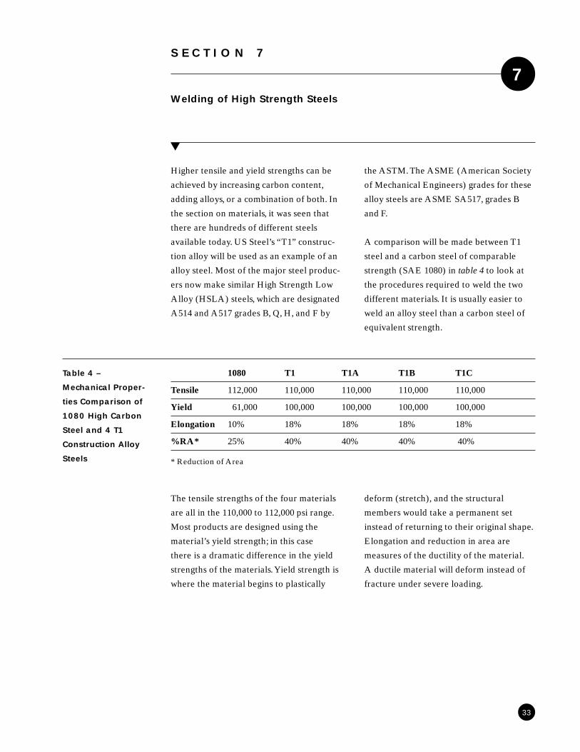
Short-arc, or short-circuit transfer, is
basically a low heat input, low penetration
process. Currents range from 40-50 amps
(.023" wire) up to 250-275 amps (0.052"
diameter wire). Voltage ranges from
14-21v. This process is a good choice on
thin material and sheet metal and has been
used extensively for out-of-position MIG
welding. Short-arc is also a good choice
where bridging gaps is a problem.
This form of metal transfer is called short-
arc because the wire does electrically short
to the workpiece. When the wire touches
the base material, the arc goes out, and the
current flowing through the wire begins to
rapidly raise the temperature of the wire.
As seen in the power supply characteristic
curve, at 0 volts the power supply tries to
produce a maximum current output. When
the wire reaches its melting point, it flows
into the puddle and the arc reignites. This
shorting takes place very rapidly, from 60
to 120 times per second. Figure 29 shows
the droplet of molten weld metal pinching
off just before the arc reignites in the
third illustration.
Figure 28 –
The Pinch Effect
Tries to Pinch Off
the End of the
Electrode
Figure 29 –
In Short-Arc Transfer,
the Electrode Shorts
60-120 Times Per
Second
P PP P
Short-Arc Globular Spray
The pinch effect is a function of current
Time (milliseconds)
Curr
ent
Voltage

After adjusting the wire feed to do the job,
the voltage can be fine-tuned to where the
sound from the arc becomes smooth and
very regular. Electrical stick-out must be
closely controlled as it has a great impact
on current levels. At the low-end condition
of 40-50 amps and 14-15 volts with a .023"
electrode, stick-out should be about 1/4".
With a .035" electrode at 80-90 amps and
15-16 volts, ESO should be about 3/8". At
the high end of short-arc transfer with a
.045" electrode, current will be at 225-235
amps and 20-22 volts. Because of the high
current levels, we increase the ESO to
preheat the electrode and reduce the
current. The ESO with these conditions
would be in the 5/8"-3/4" range. This
method gives a very controllable arc. If
the arc is unstable, the usual cause is that
the ESO is too long or voltage is too high.
There should be very little spatter with
this process, regardless of shielding gas.
Argon mixtures, however, provide smaller
droplets with better gap bridging and arc
stability as a result.
To adjust the power supply for short-arc
transfer, two variables can help, if they
are available. The slope on some machines
is adjustable, either externally, or with
internal taps. Figure 7 shows that the
steeper curve will limit the maximum
current that the power supply can deliver,
which is a real benefit when short-arc
welding at low currents on thin materials.
If the majority of your work is in the short-
arc range, it is probably worthwhile to
change an internal tap if the machine has
one. An internal tap isn’t something you
change for each job.
A power supply that has an inductance
control is easier to use for short-arc
transfer. As shown in figure 10 adding
inductance slows the rate of current rise.
With this available, after wire feed and
voltage are adjusted, inductance should be
increased to the point where the metal
begins to transfer smoothly. By increasing
the inductance, the current rises at a slower
rate, and is at a lower level when the cycle
begins again than it would be without the
inductance in the circuit. Limiting short
current reduces explosive, harsh metal
transfer. Most short arc welding is done
with .023", .035" or .045" electrodes.
Larger wires require too much current
for most applications.
Gases that work well in short-arc
span from C-8 through C-25 mixtures
(Praxair's StarGold™ blends), straight CO2
and Praxair's Stargon™ gas blend. For
low current applications carbon dioxide
is sometimes a good choice. The arc is
hotter than with an argon mixture, and
at low current levels, there is not much
spatter. For increased deposition rates and
travel speeds, C-25, C-15, or C-8 mixtures
will usually provide better results with
decreased spatter levels. Reducing the
amount of carbon dioxide makes the
puddle less fluid and easier to control.
Burn-through is also reduced. On thinner
materials, gases lower in carbon dioxide
content work best by minimizing burn-
through and permitting higher currents
and travel speeds. For welding higher
alloys, like stainless steel, helium is some-
times added to the shielding gas to
increase heat input at lower deposition
rates.
27

Globular transfer is usually not the
recommended way to deposit weld metal
because of the inefficiency of the process.
This type of transfer produces the most
spatter. Depending on the current range,
shielding gas, and power supply settings,
globular transfer can waste 10-15% of the
weld metal as spatter. Because of the
inefficiency of the process, slower travel
speeds or smaller bead sizes result at wire
feeds comparable to spray or short-arc
transfer.
When the tip of the wire begins to melt in
globular transfer as shown in figure 30, it
only shorts to the workpiece occasionally
due to higher voltages. The inconsistent
cracks and pops you hear are the breaking
of the short circuits. Unlike short-circuit
transfer, an arc is present most of the time,
and the metal begins to form a ball on the
end of the wire. This ball is held by the
surface tension and the force of the arc.
The arc is continuously moving to the
place where the glob of metal is closest to
the work, where the minimum voltage is
required to sustain the arc. This creates the
instability that you see and hear in the arc.
When the surface tension and the force of
the arc are finally overcome by gravity the
glob transfers. As the glob of metal hits the
work, it tends to splash, throwing spatter
out of the puddle onto the work.
Globular transfer occurs when voltages
and currents exceed that of the short-arc
range. Other than short-arc, this is the
only type of transfer you get with carbon
dioxide in the current range used in
industry. If you are using gas blends like
Praxair's Stargon™ and StarGold™ (Ar/O2
or Ar/CO2), globular transfer is what you
get when voltage or current falls out of the
spray transfer range. This is where spatter
develops when a spray arc mixture is used
improperly.
▲
B.GlobularTransfer
Figure 30 –
Globular Transfer
Produces High
Levels of Spatter
28
Unstable ArcHigh Spatter Levels

Spray transfer is a very clean, high effi-
ciency process. All wire diameters can be
used. For most applications in the 175 amp
to 500 amp range, .035" to 1/16" wires
work well. When the welding equipment is
set up properly, there is almost no spatter
and 97-98% of the filler weld is deposited
in the weld puddle (deposition efficiency).
In spray transfer, the tip of the electrode
becomes pointed as figure 31 shows.
Because the tip is so small, the current
density (amps/square inch) and the pinch
force are very high. This pinches off metal
droplets that are smaller than the diameter
of the wire. The droplets are accelerated by
the magnetic field, around the arc instead
of transferring by gravity as in globular
transfer. The small droplets are absorbed
into the weld pool rather than splashing.
Spray transfer can be used on materials as
thin as 14 and 16 gauge metals with the
right wire diameter (.023"). Thicker
section welding is where spray really gains
an advantage, especially in the flat and
horizontal positions. This type of metal
transfer can be used out of position but
wire diameter should be smaller and the
operating conditions less than in the flat
position. All steels (carbon and stainless),
and most other materials, can be GMAW
welded in spray transfer.
The gases used for spray are lower in
active gases (CO2 and O2) than gases for
short-arc and globular transfer. Most con-
tain from 85-90% argon, and some blends
contain both carbon dioxide and oxygen.
Some of the newer gases also contain small
additions of helium (Praxair's HeliStar™
gas blends) to increase the energy in
the arc.
▲
C.SprayTransfer
Figure 31 –
Spray Transfer
is a Very High
Efficiency Process
29
Droplets smallerthan diameter ofelectrode
Very low spatter
Minimum voltageand currentrequired

Transition Currents
(Steel and Stainless Steel)
To set a welding system for spray, there are
minimum voltages and currents required.
Voltages range from 24 v (small diameter
with Ar/O2 ) to 30 v (hi-deposition with
He). A good place to start is around
26-27 volts. To estimate what the mini-
mum transition current for spray transfer
would be, multiply the wire diameter (in
thousandths of an inch) by 10,000 and
divide by two as figure 32 shows.
This approximation is accurate for a
95% Ar/5% O2 shielding gas. If you
are using a gas with 10% CO2, a closer
approximation is made by adding the
% CO2 to the transition current calculat-
ed above and tabulated in figure 33. For
example, a .045" wire with C-10 would
produce spray transfer at approximately
225 + 10 = 235 amps and about 27 arc volts.
Figures 34 and 35 show the spray transfer
ranges for 95% Ar/5% O2 (figure 34) and
the short-arc and spray transfer regions
for Ar/8% CO2 (figure 35).
Figure 32 –
Transition Currents
for 95% Ar/5% O2
Shielding Gas
Figure 33 –
Transition Currents
with Various
Shielding Gases
30
Wire O-5 C-5 C-10 C-15
.035 175 180 185 190
.045 225 230 235 240
.052 260 265 270 275
.0625 320 320 325 330
.035 x 10,000 = 350/2 = 175 amps
.045 x 10,000 = 450/2 = 225 amps
.052 x 10,000 = 520/2 = 260 amps
.0625 x 10,000 = 625/2 = 312amps

Figure 34 –
Spray Transfer
Ranges for
95% Ar/5% O2
.035" and .045"
Electrodes
Figure 35 –
Short-Arc and Spray
Transfer Ranges for
Ar/8% CO2 (C-8)
with 0.35" and 0.45"
Electrodes
31
100 200 300 400
36
32
28
24
22
18
.035
.045
Spatt
er
Spatter
Hiss
.035" and .045"wire withO-5 gas
Current
Voltage
100 200 300 400
40
35
30
25
20
15
.035
.045
Spatt
er
Spatter
Hiss
.045" wirewith C-8 gas
Current
Voltage
Short-arc

Pulsed spray transfer is a process that
combines the lower heat inputs associated
with short-arc with the clean metal transfer
and good penetration associated with
spray transfer. A graph of current vs. time
(figure 36) shows the shape to be a square
wave. The current at the top of the square
wave is called the peak current, and the
current at the bottom of the square wave is
called the background current. The back-
ground current keeps the arc lit, but at
very low currents – typically 20-40 amp.
When the current rises to the peak current,
one droplet is transferred in spray transfer.
Because of the small size of the droplet,
spatter is minimized and penetration is
maximized due to the spray transfer.
Due to its low heat input, pulsed spray is
beneficial for out of position work and for
filling gaps. Since it can produce high peak
currents, a larger wire can usually be used
at lower deposition rates. A larger wire
(.045 instead of .035) will usually reduce
wire costs and reduce wire feeding prob-
lems, especially for materials such as
aluminum.
Recent research has shown that inverter
pulsed power supplies with very rapid
current rise can reduce the fume associ-
ated with higher current GMAW welding.
The fuming is caused by superheating the
molten tip of the wire and causing the
metal to boil. The very rapid current rise
reduces the superheating, leading to the
reduced fume generation rates.
▲
D.Pulsed SprayTransfer
Figure 36 –
Pulsed Spray
Transfer Produces
Low Heat Inputs
With Very
Clean Transfer
32
140
275
20
Peak Current
Background Current
Average Current
Time (milliseconds)
Curr
ent
S E C T I O N 7
Welding of High Strength Steels
7
▲
Higher tensile and yield strengths can be
achieved by increasing carbon content,
adding alloys, or a combination of both. In
the section on materials, it was seen that
there are hundreds of different steels
available today. US Steel’s “T1” construc-
tion alloy will be used as an example of an
alloy steel. Most of the major steel produc-
ers now make similar High Strength Low
Alloy (HSLA) steels, which are designated
A514 and A517 grades B, Q, H, and F by
the ASTM. The ASME (American Society
of Mechanical Engineers) grades for these
alloy steels are ASME SA517, grades B
and F.
A comparison will be made between T1
steel and a carbon steel of comparable
strength (SAE 1080) in table 4 to look at
the procedures required to weld the two
different materials. It is usually easier to
weld an alloy steel than a carbon steel of
equivalent strength.
1080 T1 T1A T1B T1C
Tensile 112,000 110,000 110,000 110,000 110,000
Yield 61,000 100,000 100,000 100,000 100,000
Elongation 10% 18% 18% 18% 18%
%RA* 25% 40% 40% 40% 40%
Table 4 –
Mechanical Proper-
ties Comparison of
1080 High Carbon
Steel and 4 T1
Construction Alloy
Steels
The tensile strengths of the four materials
are all in the 110,000 to 112,000 psi range.
Most products are designed using the
material’s yield strength; in this case
there is a dramatic difference in the yield
strengths of the materials. Yield strength is
where the material begins to plastically
deform (stretch), and the structural
members would take a permanent set
instead of returning to their original shape.
Elongation and reduction in area are
measures of the ductility of the material.
A ductile material will deform instead of
fracture under severe loading.
33
* Reduction of Area

T1 T1 A T1 B T1 C 1080
Carbon .1 - .2 .12 - .21 .12 - .21 .14 - .21 .78 - .89
Manganese .6 - 1.0 .7 - 1.0 .95 - 1.3 .95 - 1.3 .6 - .9
Phos (max) .035 .035 .035 .035 .04
Sulfur (max) .04 .04 .04 .04 .05
Silicon .15 - .35 .2 - .35 .2 - .35 .15 - .35
Nickel .7 - 1.0 1.2 - 1.5
Copper .15 - .5
Chrome .4 - .65 .4 -.65 .4 - .65 1.0 - 1.5
Molybdenum .4 -.6 .15 - .25 .2 - .3 .4 - .6
Vanadium .03 -.08 .03 - .08 .03 - .08 .03 - .08
Boron .0005 - .006 .0005 - .005 .0005 - .005
Titanium .01 - .03
Table 5 –
Comparison
of Chemical
Compositions of
1080 and T1 Alloys
of Equal Tensile
Strengths
Welding of high strength steels is different
than welding low carbon steels. The welder
must pay a lot more attention to detail
when welding high strength steels.
▲
A.Select theProperFiller Metal
If standard T1 steel were to be welded the
tensile strength of the material should be
considered. From table 4 it is seen that the
tensile strength is 110,000 psi. For the
GMAW process, an ER110S-1 electrode
could be used. The 110 indicates a tensile
strength of 110,000 psi. Some manufactur-
ers also develop electrodes that do not
exactly fit in the AWS classifications. These
electrodes can also be used, but a welding
engineer should look at the mechanical
properties to ensure compatibility. If
the FCAW process were to be used, an
E110T5-K3 (Mn-Ni-Cr) or an E110T5-K4
(Mn-Ni-Cr-Mo) would be selected accord-
ing to the mechanical properties required.
34

Molten weld metal is capable of absorb-
ing considerable amounts of hydrogen.
Hydrogen in weld metal causes two
problems, porosity and cracking. Hydrogen
can come from a variety of sources, and all
of them can cause problems. Hydrogen is
normally found in nature as a diatomic
molecule, H2.
In the arc, the hydrogen immediately
dissociates to monatomic hydrogen (H),
which is the smallest atom known. A single
hydrogen atom is about 1/100,000 the
diameter of an iron atom. The hydrogen
atoms are very soluble in the weld metal.
Some of the hydrogen sources are:
1. Grease, Oil, Oxidation or Paint on the
Part or Electrode
Grease and oil are both hydrocarbons, and
in the heat of the arc (about 10,000ºF), will
rapidly dissociate to produce hydrogen,
carbon, and other contaminants in the
puddle. The carbon can over-harden the
weld metal with possible carbon increases
of .1 to .25%. Hydrogen goes into solution
in the weld metal. Some paints are also
hydrocarbon based, leading to the same
problems as oil and grease. Mill scale and
rust can also contain moisture. When
the arc heats these materials, the water
molecules are dissociated into hydrogen
and oxygen. Both of these gases go into
solution in the weld metal and can cause
weld problems such as porosity and
cracking.
2. Excess Drawing Lubricants
on the Electrode
Drawing lubricants on the wire electrode
can also contain hydrocarbons. When they
are exposed to the arc heat, they dissociate
and contaminate the puddle.
3. Moisture
Moisture can come from surface contami-
nants such as rust and mill scale, and it can
be adsorbed on the surface of a clean sheet
of steel. Bringing a piece of high strength
steel inside in the winter will sometimes
cause moisture to condense on the surface.
For T1, it is recommended that the mate-
rial temperature be at least 70 F before
welding begins.
Moisture can also come from the shielding
gas if there is a leak in the supply line as
discussed in the shielding gas section. Air
contains oxygen, nitrogen, and moisture, all
of which are detrimental to the integrity of
the weld metal.
As the puddle freezes, the solubility of
hydrogen in the puddle decreases. The
hydrogen tries to escape from the weld
metal by two different mechanisms.
• Porosity Formation
If the concentration of hydrogen in
the matrix exceeds its solubility in the
solidified weld metal, the excess hydro-
gen can form bubbles of hydrogen gas.
These bubbles can show up as porosity in
an x-ray. At very high concentrations of
hydrogen they can cause visible porosity
at the face of the weld.
▲
B.MinimizeHydrogenContamination
35

• Slowly Diffuses Out of the Weld Metal
After welding is completed, hydrogen
continues to rapidly diffuse out of the
weld metal. In lab tests for measuring
diffusible hydrogen, the welded coupon
is quickly inserted in a bath of liquid
nitrogen. The sample is then placed in
mercury, and the quantity of hydrogen
released is measured over time. If the
hydrogen content is high enough, there
are visible streams of bubbles rising from
the coupon. The rest of the diffusible
hydrogen will escape within 20 to 30
days. The remaining hydrogen in the
weld metal is called residual hydrogen,
and it can cause cracking problems after
welding.
During the welding process, the base
metal in contact with the molten puddle
was subjected to temperatures very close
to the melting temperature of the material.
In that period, hydrogen atoms also diffuse
into the base metal in what is referred to
as the heat affected zone (HAZ - see
figure 37). The solubility of hydrogen
increases with temperature even when the
metal remains a solid.
The diffusion of the hydrogen into the
base metal in conjunction with the very
rapid cooling rate can lead to underbead
cracking or delayed brittle fracture.
▲
C.ControlHeat Input
To understand the welding of the higher
strength steels, it is necessary to know a
little about what happens when steels
solidify. As molten metal cools, it under-
goes a transformation from a phase called
austenite to a number of different struc-
tures. A low carbon steel like a 1008 grade
changes from austenite to ferrite, which is
a very soft and ductile microstructure.
Adding slightly more carbon and cooling
more slowly forms a microstructure called
pearlite, which is ferrite and cementite
(Fe3C). When carbon and other alloying
elements are added, the transformation
from austenite is modified to form harder
and sometimes more brittle microstruc-
tures. The cooling rate of the weld metal
and the HAZ is very important in deter-
mining the properties of the material.
A familiar microstructure found in metal
files is called martensite. Martensite is
very strong, with a tensile strength of
200,000 psi or more, but the microstructure
is very brittle. Martensite can be formed
by very rapid cooling of the material. If a
file is heated to 1300 F - 1400 F and then
cooled very slowly, a hole can be drilled in
it. If it is then reheated and quenched in
oil, martensite will reform and the file can
be used again. There is also an intermedi-
ate microstructure called bainite, between
pearlite and martensite, which has proper-
ties that fall between the two.
36
Figure 37 –
Hydrogen is Driven
Into the HAZ by
Stress Gradients
HAZ

Preheat and Interpass Temperature ( F)
70 150 200 300 400
Thickness 3/16" 27 23 21 17 13
1/4" 36 32 29 24 19
1/2" 70 62 56 47 40
3/4" 121 107 99 82 65
1" Any 188 173 126 93
1 1/4" Any Any Any 175 127
1 1/2" Any Any Any Any 165
2" Any Any Any Any Any
Metallurgists use charts called continuous
cooling transformation (CCT) diagrams to
determine the cooling rates required to
obtain certain microstructures. A CCT
diagram tells what microstructure to
expect when cooling occurs at different
rates. At the bottom of the chart are three
different scales for air, oil, and water
quenching. Air cooling produces the
slowest cooling rate with a water quench
being the fastest. Welding on a piece of
base metal that has just been brought in
the shop from the yard on a very cold day
can produce some very rapid cooling rates.
The reason why a CCT diagram is men-
tioned is that weld metal and the heat
affected zone (HAZ) also go through the
same cooling process after welding. The
HAZ is the base metal right next to the
weld metal that almost reached its melting
temperature. The cooling rate of the HAZ
is much faster than the weld metal because
the base metal is acting like a quenching
medium. This is the reason that the heat
input must be controlled during the
welding of the high strength steels. For T1,
higher heat inputs lead to grain growth in
the HAZ, and the strength of the material
is reduced.
To control the cooling rate, minimum
preheat and interpass temperatures are
specified to avoid a brittle crack sensitive
HAZ and weld metal.
Table 6 below shows the maximum heat
inputs for T1 for different thicknesses and
preheat and interpass temperatures.
Table 6 –
Maximum
Allowable
Heat Input
for T1 Steel
in Kilojoules Per
Inch of Weld
37

The thicker the material is the higher the
allowable heat input. Some of the thicker
materials have no maximum heat input
because there is sufficient material to
ensure a rapid cooling rate with currently
available welding processes. To check
interpass temperature, use a temperature
indicating crayon 1/2" to 1" away from the
joint. It is possible to contaminate the weld
with the temperature stick, and it is the
temperature of the base metal, not the
previous pass, that is important.
If the preheat and interpass temperatures
for T1 steel are compared with those for
1080, a real difference is seen. The 1080
steel has a carbon equivalent of up to
1.03%. The steel with 1% carbon would
require preheat and interpass tempera-
tures of between 600 F and 800 F depend-
ing on thickness. A post weld heat treat-
ment at high temperature would also
probably be required to prevent cracking.
Compared to the preheat requirements
(70 F) in table 6, it is easy to see that T1
steel is much easier to weld than the
equivalent strength carbon steel. The
alloying additions in T1 steel undergo
transformation to carbides at higher
temperatures than the carbon steels, which
allows the greatly reduced preheat and
interpass temperatures.
For materials that require a slow cooling
rate to avoid cracking, it is also very
important to control preheat and interpass
temperature. A highly strained microstruc-
ture, such as that created by rapid cooling,
is very sensitive to hydrogen.
Any hydrogen in the weld metal will
diffuse into the highly strained microstruc-
ture and could lead to underbead cracking.
Hydrogen in a strained microstructure can
also lead to a problem called delayed
brittle fracture. Delayed brittle fracture is
a weld defect that does not show up
immediately. The product can be in service
for a period of time, and then fail at loads
well below the yield strength of the
material. Since the hydrogen atom is about
1/100,000 the size of an iron atom, it can
diffuse through the metal easily. Stress
gradients in the material cause the hydro-
gen atom to migrate and concentrate in
areas of high triaxial (3 dimensional)
stress. In the matrix, these areas would be
at the tip of a microcrack, a grain bound-
ary imperfection, or at the base of a
surface imperfection, such as undercut.
When the hydrogen concentration reaches
a critical level, the crack grows slightly to
relieve the stress. The diffusion mechanism
begins again at the tip of the new crack,
and the process repeats itself. As the crack
continues to grow, the material resisting
the load decreases. At some point, rapid
crack growth occurs, and there is cata-
strophic failure.
38

The correct technique incorporates all of
the topics just mentioned, such as control-
ling hydrogen and watching heat input.
With high strength materials, it is also very
important to watch torch angle. The ideal
fillet has a flat face and the toes blend into
the side wall smoothly. No undercut can
be tolerated in high strength materials,
because undercut acts just like a notch to
greatly reduce the stress at which the
component fails. A bolt that fails in the
first thread illustrates how undercut can
affect weld properties. The thread, just like
undercut, (called a stress riser) is basically
the beginning of a crack. Undercut will
also increase the strain in the material
directly below it and make it more sensi-
tive to any residual hydrogen that may be
in the material.
When beginning to weld, it is very good
practice to use the back step technique.
The back step technique involves starting
to weld 1/4"-3/8" ahead of where the
beginning of the weld is required, and then
backing up to the beginning. The beginning
of a weld usually cools too rapidly because
the base metal has not been preheated
from the heat of the arc. Back stepping
begins to preheat the material, and greatly
reduces the possibility of lack of fusion
because the material where you strike the
arc will be re-melted.
Weaving is also not recommended on
higher strength materials. A stringer bead
technique gives better results, and helps
control heat input. If heat input were
calculated using a weaving technique, it
would probably be difficult to control the
maximum heat input due to the slow travel
speeds associated with weaving.
▲
D.Use theCorrectTechnique
39

Technique is very important when welding
any type of material, and gets more
important as the material strength in-
creases. Torch angle, feed roll tension,
S E C T I O N 8
Technique and Equipment Set-Up
8
▲
▲
A.TorchAngle
There is a specific amount of energy
available from the arc to heat and melt the
base metal. Torch angle plays a very
important role in the shape of the bead
and the depth of penetration into the base
metal as figure 38 shows. A leading (or
push) angle will use some of the arc energy
to preheat the base metal before it is
welded. Because of the elevated tempera-
ture of the base metal, the bead will cool
more slowly. This allows the face of the
weld to come to equilibrium and will give a
relatively flat face. If a lagging (or drag)
angle is used, very little of the arc energy
goes into preheating the base metal, and
deeper penetration is the result. Because
of the lack of preheat, the bead will tend to
be convex (humped) because the weld will
cool more quickly. If a line were drawn
between the toes of the weld, the weld
metal above that line is wasted. If a
fracture were to occur, it would start at
the toe of the weld, not through the thick
section. In fatigue service, a humped bead
actually reduces the service life of the
component. The decreased reentry angle
(angle that the bead face makes with the
base metal) tends to raise the stress level
at the toe of the weld. A flat bead face
distributes the stress more evenly across
the joint. A slight drag angle does work
well in a deep groove, and also in the first
pass of a multi-pass weld. As a first pass,
the benefit of increased penetration is
obtained, but it is critical to be sure to melt
out the toes of the first pass when the cap
passes are put in. A lack of fusion at the
toe of the first pass is a defect that will
reduce the service life of the component.
burnback, arc and puddle position, vertical
down welds, gaps, crater filling, and arc
starting will be discussed here.
Figure 38 –
Torch Angle Affects
Penetration and
Bead Shape
40
Travel
Lead Angle (Push) Lag Angle (Pull)

pressure on the wire to deform it between
the feed rolls. Figure 39 shows the shape of
the wire as it leaves a two U-grooved roller
setup with excessive pressure. The “fin”
will be scraped off as it feeds through the
liner, and will make it more difficult to
feed the wire as the excess material begins
to clog the liner. Excessive pressure on the
feed roll will wear out the feed rolls, plug
up the liners, and usually lead to a burn-
backs at the tip.
The best method of adjusting feed roll
tension involves running about a foot of
wire out of the gun. Bend the wire 180 to
form a curved end and run the wire into a
gloved hand. Pull the trigger and slowly
adjust the feed roll pressure until the wire
will make the turn and feed smoothly. At
this feed roll pressure, the wire will feed
without deforming and the rolls will slip if
you get a burnback instead of “bird nesting”.
Setting feed roll tension is important to
improving consumable life and reducing
downtime due to feeding problems. How
many times have you seen a welder have a
feeding problem “corrected” by increasing
feed roll pressure? There are two main
types of feed roll designs used for solid
wires, one grooved and one flat roll, or two
grooved rolls. Increasing feed roll tension
on either design can actually put enough
▲
B.Feed RollTension
Figure 39 –
Feed Roll Tension
Adjustment
▲
C.Burnback
The burnback control is designed to
reduce the stick-out at the end of a weld
and keep the wire from sticking in the
puddle. When welding begins, the trigger
on the gun closes the contacts in the
welder, opens the gas solenoid, and starts
the wire feed motor as shown in figure 40.
When you release the trigger at the end of
the weld, the gas solenoid and the contac-
tor can react very quickly. The motor has
the inertia of the armature, the gearbox,
and the feed rolls to overcome, so it does
not stop instantly. What a burnback control
does is put a timer in the circuit that delays
the opening of the contactor and the clos-
ing of the gas solenoid. This allows the
motor to spin down and the wire to con-
tinue to burn off so you don’t have to try
to start the next weld with too much stick-
out. A short stick-out greatly improves
the starting of the arc because more
current is available. 41
Figure 40 –
The Burnback
Control Is Essentially
a Timer
Too much feed roll pressure deforms the wireand causes slivers to form
Slivers clog the liner and make the wire harderto feed
Apply just enough tension that the wire feedsinto a gloved hand and exits at 180
Time
Burnback is a timer that controls the ESOfor the start of the next weld
Wir
e fe
ed s
pee
d
Motor upto speed
Motoroff
Gas oncontactorclosed feedmotor on
Gas off
Contactor off

It is very important to watch the position
of your puddle in relation to the arc. In
order to get good fusion into both pieces
of base metal, the heat from the arc must
be directed onto the base metal (figure 41).
If a very large fillet is attempted in one
pass, the tendency is to try to hold the
puddle back with the arc. The puddle will
continue to advance, and trying to hold the
puddle back with the arc will lead to in-
complete fusion into the side wall. When
the puddle rolls under the arc, the heat of
the arc is no longer being put into the base
metal, it is going into the puddle. This
increases the temperature of the puddle
and reduces the fusion into the walls. This
is sometimes called “slugging” the joint.
This is a very poor practice and leads to
welds that will fail at well below their
design strength.
Vertical down welding (figure 42) can be
done properly, but the weld parameters
must be set very carefully. The problem
with vertical down welding is that it is very
easy to get lack of fusion into the side wall.
If you have watched a welder putting in a
vertical down weld and seen the molten
metal hitting the floor, this is very similar
to “slugging” a joint mentioned before in
that the only path to the floor is between
the arc and the base metal. If the weld
metal is taking this path, the arc energy
cannot be going into the base metal.
A high quality vertical down weld can be
made in either short-arc or spray transfer,
but the arc must stay in front of the
puddle. Here is one more place where a
lagging angle is beneficial, because the
arc force can be used to hold the puddle
in place as it begins to cool.
▲
D.Arc andPuddle Position
▲E.Vertical DownWelding
Figure 41 –
Stay in Front of the
Puddle with the Arc
Figure 42 –
Vertical Down
Welding Can Produce
a High Quality Joint
42
If you get on topof the puddle, lackof fushion and cold-lap can result
Use a drag angle
Stay in front of thepuddle
Use short-arc pulsed sprayor low current spray transfer
Use a smallerdiameter electrode
Very littlemetal shouldfall past thepuddle
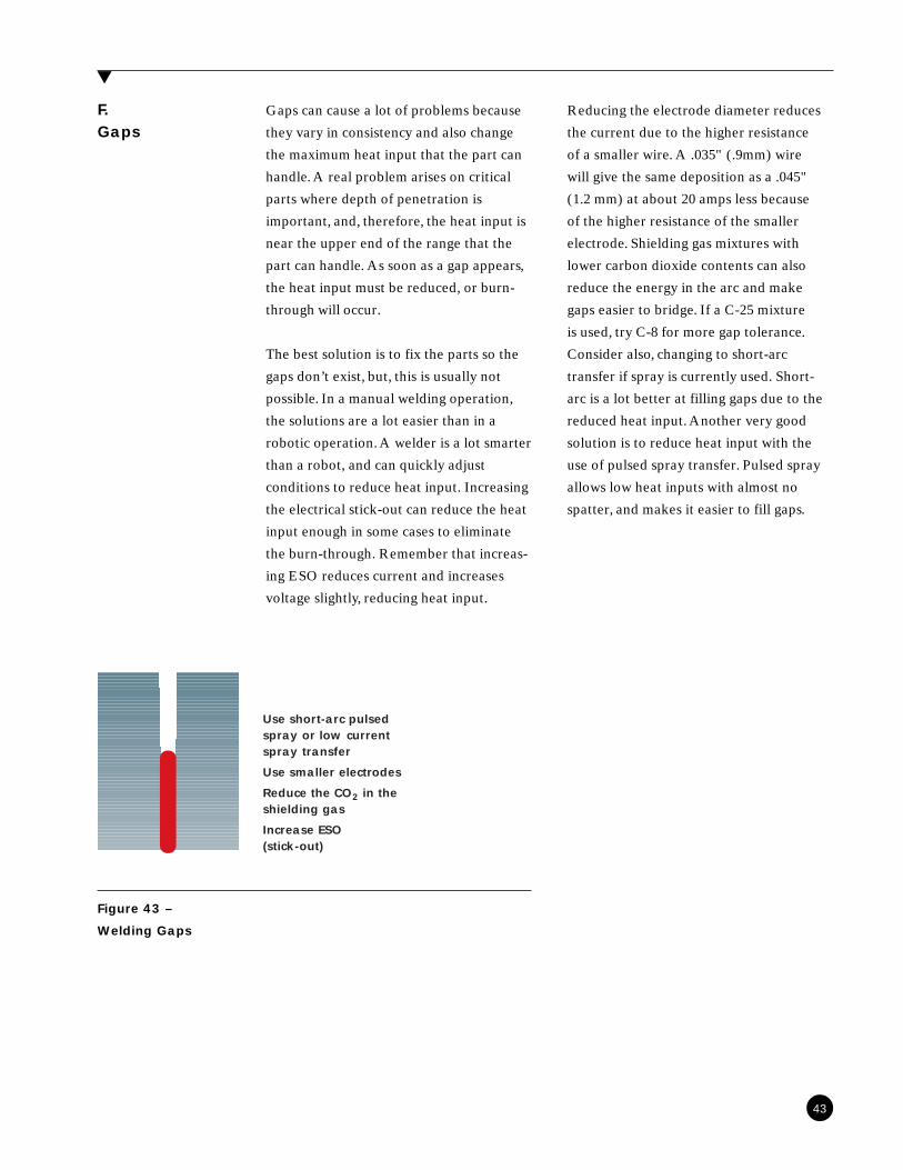
Gaps can cause a lot of problems because
they vary in consistency and also change
the maximum heat input that the part can
handle. A real problem arises on critical
parts where depth of penetration is
important, and, therefore, the heat input is
near the upper end of the range that the
part can handle. As soon as a gap appears,
the heat input must be reduced, or burn-
through will occur.
The best solution is to fix the parts so the
gaps don’t exist, but, this is usually not
possible. In a manual welding operation,
the solutions are a lot easier than in a
robotic operation. A welder is a lot smarter
than a robot, and can quickly adjust
conditions to reduce heat input. Increasing
the electrical stick-out can reduce the heat
input enough in some cases to eliminate
the burn-through. Remember that increas-
ing ESO reduces current and increases
voltage slightly, reducing heat input.
Reducing the electrode diameter reduces
the current due to the higher resistance
of a smaller wire. A .035" (.9mm) wire
will give the same deposition as a .045"
(1.2 mm) at about 20 amps less because
of the higher resistance of the smaller
electrode. Shielding gas mixtures with
lower carbon dioxide contents can also
reduce the energy in the arc and make
gaps easier to bridge. If a C-25 mixture
is used, try C-8 for more gap tolerance.
Consider also, changing to short-arc
transfer if spray is currently used. Short-
arc is a lot better at filling gaps due to the
reduced heat input. Another very good
solution is to reduce heat input with the
use of pulsed spray transfer. Pulsed spray
allows low heat inputs with almost no
spatter, and makes it easier to fill gaps.
▲
F.Gaps
43
Figure 43 –
Welding Gaps
Use short-arc pulsedspray or low currentspray transfer
Use smaller electrodes
Reduce the CO2 in theshielding gas
Increase ESO(stick-out)
Initiating the arc is mainly a function of
the current available. The biggest cause of
poor arc starting is too much stick-out.
The extra resistance heats the wire and
reduces the current available for arc
initiation. When the wire has heated
enough to soften it buckles and the arc
goes out. Then the whole process begins
again, leaving little stubs of wire at the
start of the weld.
Another problem seen on a regular basis is
poor connections on the work and the hot
leads. When copper is new, it is bright and
highly conductive. As it ages, the copper
surface oxidizes and acts as an insulator.
This resistance causes the cables to get hot
during welding.
The current rise begins when the arc starts,
is slowed by the additional resistance in
the welding circuit. Replacement of the
poor connections will restore arc starting.
Sealing the exposed copper with a liquid
electrical tape will prevent oxidation from
occurring.
At higher current levels, also consider the
slope and inductance setting on the power
supply. A steep slope or high inductance
setting is designed to limit short-circuit
current. If the material to be welded is not
too thin, a flat slope and/or minimum
inductance will improve the arc starting
by increasing the rate of current rise.
▲
G.CraterFilling
little more time filling in the crater before
ending the weld. This will add a little more
weld metal to increase the reinforcement
and also put some additional energy into
the weld to slow the cooling rate. Slowing
the cooling rate will allow more time for
the gases in solution to escape through the
face of the weld.
The crater is the last bit of weld metal to
freeze at the end of a weld. Due to the
shrinkage that occurs as the weld metal
cools, the crater will sometimes appear
concave. This can cause problems because
it is highly strained weld metal with very
little reinforcement because of the concav-
ity. Highly strained weld metal with very
little reinforcement can develop cracks
very easily. Porosity in the crater is also
possible. The solution to this is to spend a
▲
H.Arc Starting
44

S E C T I O N 9
Weld Discontinuities and Problems
9
▲
defect when the component is rendered
unserviceable.
The AWS defines discontinuities as
interruptions in the typical structure of a
weldment. A discontinuity only becomes a
▲
A.Lack ofFusion
Lack of fusion, is little or no penetration
and tie-in to the base metals, as shown in
figure 44. This can be caused by many
different reasons. Some of the common
ones are:
1. Torch Not Centered: This concentrates
the heat of the arc on only one of the
pieces. If both pieces to be joined are not
melted by the arc, the molten puddle will
have a tendency to lie on top of the second
piece without fusing to it.
2. Poor Torch Oscillation: If a welder
makes “little circles” with the torch, it is
easier to make a pretty bead, but there is
a good chance for lack of fusion. As the
torch moves back into the puddle, the
molten metal doesn’t stop and wait. It
continues to advance, but without the
benefit of the intense heat of the arc to
melt the base metal. The puddle just lies
on top of the work instead of fusing to it.
Exaggerated oscillation produces the
same problem.
3. Excessive Travel Speed: If the travel
speed is too high, it is possible to not spend
enough time to allow fusion with the base
metal. There is a minimum amount of heat
required for every welding joint, because
the base metal can cool the puddle very
rapidly after it is deposited.
4. Vertical Down Welding is notorious for
lack of fusion at the toes (where the weld
metal intersects the base metal) and very
little penetration. This lack of fusion can
also occur in flat and horizontal positions
where it is called overlap, or cold lap. Lack
of fusion in vertical down welds is usually
caused by getting on top of the weld
puddle. This prevents the arc from ad-
equately heating the base material to
produce proper fusion. An old slang term
for this defect is fingernailing because if it
is bad enough, you can insert a fingernail
beneath it.
45
Figure 44 –
Lack of Fusion

5. Travel Speed Too Slow: It is similar to
improper torch oscillation. The heat from
the arc is used to further heat the already
molten puddle and raise its temperature
instead melting the base metal.
6. Current Too Low can also cause lack of
fusion. This is usually only a problem on
thicker sections, where the base metal pulls
heat out of the puddle very rapidly.
7. Incorrect Welding Parameters is the
last major cause for lack of fusion. This
category would include all the variables
covered plus incorrect ESO (electrical
stick out), torch angle wrong, incorrect
shielding gas, etc.
▲
B.Porosity
Porosity (figure 45) can be a significant
problem, and not easily solved. The biggest
causes are probably contamination of the
shielding gas, followed by filler metal and
base metal contamination. A leak any-
where in the distribution system from a
leaking fitting in the ceiling to a loose hose
fitting at the feeder will allow gas to leak
out and air to diffuse into the shielding gas.
Molten weld metal holds a lot more
nitrogen, oxygen, and hydrogen (from
moisture in the air) than solid metal. As
the weld puddle freezes, the gases come
out of solution and form porosity.
Figure 45 –
Porosity in a
Weld
46
Another form of contamination can come
from the base metals. It is against better
welding practice to weld over paint, mark-
er lines, water, rust, oil, and heavy mill
scale. Paint and markers are typically made
of hydrocarbons. The heat from the arc
breaks down these compounds to release
hydrogen, carbon and other contaminants
into the weld pool. Mill scale and rust
can also contain a lot of moisture that is
dissociated in the arc to form oxygen and
hydrogen. Although this is not such a big
problem on low carbon steels, on higher
alloys it can cause cracking that sometimes
doesn’t show up until the component is in
service.
Additions of higher thermal conductivity
gases (He & CO2) and higher alloy content
wires (ER70S-6, S-7) can help to reduce
porosity. Helium and carbon dioxide
increase the energy being put into the
puddle, so the cooling rate is slower. The
slower cooling rate gives more time for
the gases to leave the puddle instead of
causing porosity. The increased deoxidizer
levels in some wires will also reduce por-
osity if the cause of the porosity is associ-
ated with oxygen levels (not high nitrogen
levels due to gas leaks). These deoxidizers
will tie up the oxygen and float it to the
surface as liquid oxides that freeze to form
slag islands.
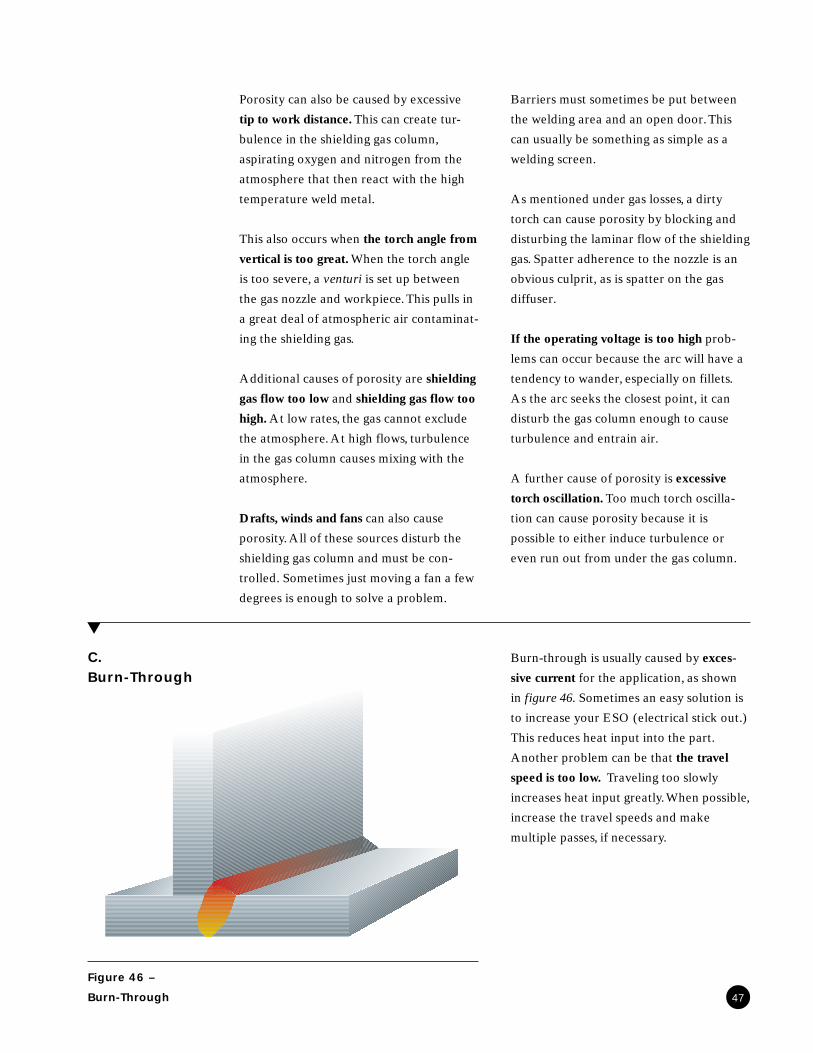
Porosity can also be caused by excessive
tip to work distance. This can create tur-
bulence in the shielding gas column,
aspirating oxygen and nitrogen from the
atmosphere that then react with the high
temperature weld metal.
This also occurs when the torch angle from
vertical is too great. When the torch angle
is too severe, a venturi is set up between
the gas nozzle and workpiece. This pulls in
a great deal of atmospheric air contaminat-
ing the shielding gas.
Additional causes of porosity are shielding
gas flow too low and shielding gas flow too
high. At low rates, the gas cannot exclude
the atmosphere. At high flows, turbulence
in the gas column causes mixing with the
atmosphere.
Drafts, winds and fans can also cause
porosity. All of these sources disturb the
shielding gas column and must be con-
trolled. Sometimes just moving a fan a few
degrees is enough to solve a problem.
Barriers must sometimes be put between
the welding area and an open door. This
can usually be something as simple as a
welding screen.
As mentioned under gas losses, a dirty
torch can cause porosity by blocking and
disturbing the laminar flow of the shielding
gas. Spatter adherence to the nozzle is an
obvious culprit, as is spatter on the gas
diffuser.
If the operating voltage is too high prob-
lems can occur because the arc will have a
tendency to wander, especially on fillets.
As the arc seeks the closest point, it can
disturb the gas column enough to cause
turbulence and entrain air.
A further cause of porosity is excessive
torch oscillation. Too much torch oscilla-
tion can cause porosity because it is
possible to either induce turbulence or
even run out from under the gas column.
Burn-through is usually caused by exces-
sive current for the application, as shown
in figure 46. Sometimes an easy solution is
to increase your ESO (electrical stick out.)
This reduces heat input into the part.
Another problem can be that the travel
speed is too low. Traveling too slowly
increases heat input greatly. When possible,
increase the travel speeds and make
multiple passes, if necessary.
▲
C.Burn-Through
Figure 46 –
Burn-Through 47

Incorrect wire diameter is also a cause of
burn-through. Reducing the wire diameter
allows you to weld at lower currents but at
the same deposition rate with reduced heat
input. One more variable that can cause
additional heat is using the incorrect
shielding gas. The shielding gas can be
tailored to the application to help control
the heat input.
Excessive gaps can also be a cause of burn-
through, as every manual welder knows.
This is easy to forget on robots and mecha-
nized welds, and sometimes, mysterious
burn-through occurs because the robot
can’t compensate by changing conditions
when faced with gaps like a welder can. If
the parts can’t be made to fit better, gaps
can be pre-welded or “stringered” with a
short-bead prior to final welding.
Undercut (figure 47) has three main
causes. The first is excessive voltage, which
can cause the arc to wander. The melted
area of the basemetal is too large for the
puddle to flow into and fill the undercut
area. High travel speeds can lead to under-
cut for the same reason. The heat input is
too low to allow the weld metal to flow
and the bead is generally convex. On
horizontal fillets, undercut can be caused
by incorrect torch position. If the torch is
positioned on the vertical leg, there is no
way for the weld metal to flow uphill
against the force of gravity. Repositioning
the torch 1-2 wire diameters out from the
root on the horizontal plate will eliminate
the undercut. Undercut is a very serious
defect on high strength materials because
it greatly increases the strain in the mater-
ial just below the notch and increases its
sensitivity to hydrogen cracking.▲
D.Undercut
48
Figure 47 –
Undercut on the
Upper Leg of a
Fillet Weld
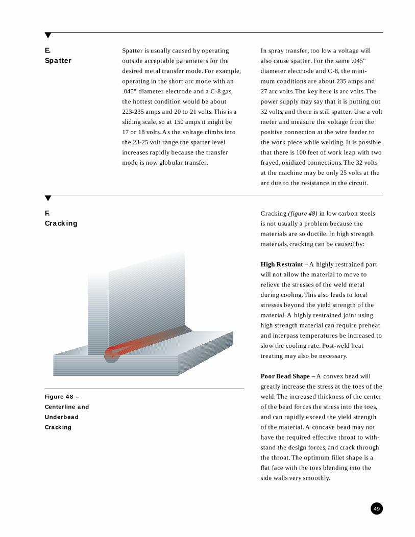
Spatter is usually caused by operating
outside acceptable parameters for the
desired metal transfer mode. For example,
operating in the short arc mode with an
.045" diameter electrode and a C-8 gas,
the hottest condition would be about
223-235 amps and 20 to 21 volts. This is a
sliding scale, so at 150 amps it might be
17 or 18 volts. As the voltage climbs into
the 23-25 volt range the spatter level
increases rapidly because the transfer
mode is now globular transfer.
▲
E.Spatter
In spray transfer, too low a voltage will
also cause spatter. For the same .045"
diameter electrode and C-8, the mini-
mum conditions are about 235 amps and
27 arc volts. The key here is arc volts. The
power supply may say that it is putting out
32 volts, and there is still spatter. Use a volt
meter and measure the voltage from the
positive connection at the wire feeder to
the work piece while welding. It is possible
that there is 100 feet of work leap with two
frayed, oxidized connections. The 32 volts
at the machine may be only 25 volts at the
arc due to the resistance in the circuit.
Cracking (figure 48) in low carbon steels
is not usually a problem because the
materials are so ductile. In high strength
materials, cracking can be caused by:
High Restraint – A highly restrained part
will not allow the material to move to
relieve the stresses of the weld metal
during cooling. This also leads to local
stresses beyond the yield strength of the
material. A highly restrained joint using
high strength material can require preheat
and interpass temperatures be increased to
slow the cooling rate. Post-weld heat
treating may also be necessary.
Poor Bead Shape – A convex bead will
greatly increase the stress at the toes of the
weld. The increased thickness of the center
of the bead forces the stress into the toes,
and can rapidly exceed the yield strength
of the material. A concave bead may not
have the required effective throat to with-
stand the design forces, and crack through
the throat. The optimum fillet shape is a
flat face with the toes blending into the
side walls very smoothly.
▲
F.Cracking
Figure 48 –
Centerline and
Underbead
Cracking
49

S E C T I O N 10
Conclusion
10
▲
Hopefully this course has given you a little
better understanding of the Gas Metal Arc
Welding Process.
With the knowledge you have, and this
booklet to use as a reference, it is hoped
that you’re now a more informed welder
and your job has been made easier. Please
call your local Praxair engineering repre-
sentative with any questions that you have
in the future.
50

WORLD HEADQUARTERSPraxair, Inc.39 Old Ridgebury RoadDanbury, CT 06810-5113Tel: 1-800-PRAXAIR
(1-800-772-9247)(716) 879-4077
Fax: 1-800-772-9985(716) 879-2040
Internet: www.praxair.come-mail: [email protected]
The information contained herein is offered
for use by technically qualified personnel at
their discretion and risk, without warranty
of any kind.
PRAXAIR, the FLOWING AIRSTREAM
design, HELISTAR, STARGOLD and
STARGON are trademarks or registered
trademarks of Praxair Technology, Inc. in
the United States and other countries.
Copyright © 1996, 1997, 1998, 1999
Praxair Technology, Inc. All Rights Reserved.
P-8107B 2M 9/99