Embed Size (px)
Citation preview

1
Advance Steel
User’s Guide

This document only contains a brief description of the software functions andmay only be used as a guide for using the software. It can also include infor-mation about some modules you did not acquire. For detailed information re-garding the program's functions, please refer to the online help provided inAdvance.In case of any discrepancy between the information given in this guide andthe information given in the software, consider the software as your main ref-erence.The content of this guide is subject to change without notice. Any reproduc-tion or distribution, even if partial, by any means - electronically or mechani-cally - of the contents of the present guide and other supplied documentationis strictly forbidden if made without GRAITEC explicit authorization.© GRAITEC, Bièvres. All rights reserved.Windows 2000® and Windows XP® are trade marks or registered trade-marks of the Microsoft Corporation.DXF™ and AutoCAD® are trademarks or registered trademarks of AutoDeskInc. San Rafael, CA.All the other marks belong to their owners.

ADVANCE STEEL USER’S GUIDE
3
TABLE OF CONTENTS
WELCOME ................................................................................................................... 7Introduction..........................................................................................................................................8Advance...............................................................................................................................................8Specialized areas ................................................................................................................................9Advance and AutoCAD .......................................................................................................................9Technology........................................................................................................................................10Communication options.....................................................................................................................10Individual preferences .......................................................................................................................10
Installation................................................................................................................. 11General..............................................................................................................................................12System requirements ........................................................................................................................12
Hardware.................................................................................................................................12Software ..................................................................................................................................12
Distribution.........................................................................................................................................12License ..............................................................................................................................................13
How to obtain your user license?............................................................................................13Using USB dongles ...........................................................................................................................13Installation .........................................................................................................................................13Authorize the software.......................................................................................................................20License Management ........................................................................................................................22Installation for existing AdvanceSteel users......................................................................................22Converting database (Merging).........................................................................................................23Support ..............................................................................................................................................26Support by telephone ........................................................................................................................26
The 3D-Model ............................................................................................................ 27Elements of the 3D-model.................................................................................................................28
Beam & Plate ..........................................................................................................................28Processing...............................................................................................................................29Bolt patterns & welds ..............................................................................................................29Joints .......................................................................................................................................30Structural elements .................................................................................................................31Auxiliary objects ......................................................................................................................32Special parts ...........................................................................................................................32
3D-Modelling workflow ......................................................................................................................33
Advance Interface ..................................................................................................... 35Starting the program / working environment .....................................................................................36Advance toolbars / menus.................................................................................................................36Using Advance ..................................................................................................................................39
Other important tools for using Advance.................................................................................40Create Advance objects ....................................................................................................................40
Object properties.....................................................................................................................41Layer .......................................................................................................................................42
Creating a 3D-Model ................................................................................................. 43Create building grid ...........................................................................................................................44Creating a beam................................................................................................................................46
Straight beams ........................................................................................................................47Compound sections ................................................................................................................48

ADVANCE STEEL USER’S GUIDE
4
Curved beams.........................................................................................................................49Poly beams..............................................................................................................................50Folded profile...........................................................................................................................50Construction systems (Cold rolled profiles) ............................................................................52Welded beams ........................................................................................................................52
Create plates .....................................................................................................................................53Rectangular plate ....................................................................................................................54Polygon plate...........................................................................................................................55Gusset plates ..........................................................................................................................56Split / merge - plates ...............................................................................................................57Shrink/enlarge polygon plate...................................................................................................57Folded plate.............................................................................................................................58
Coordinate systems...........................................................................................................................59Object Coordinate Systems ....................................................................................................60Coordinate systems at curved beams.....................................................................................61UCS at bisecting line...............................................................................................................62Define coordinate system........................................................................................................62
Beam processing...............................................................................................................................63Processing objects ..................................................................................................................63Rule-based beam processing .................................................................................................64Process section .......................................................................................................................64Section contour .......................................................................................................................66
Plate processing ................................................................................................................................67Plate processing – weld preparation.......................................................................................67Cut plate at UCS .....................................................................................................................68Cut plate at plate .....................................................................................................................68Plate processing – independent from the UCS.......................................................................69Plate processing – dependent on the UCS.............................................................................70Corner processing...................................................................................................................70Polygon plate processing ........................................................................................................71
Change Advance objects ..................................................................................................................71Change by grips ......................................................................................................................72AutoCAD-Manipulating tools ...................................................................................................72AutoCAD command properties ...............................................................................................73
Advance command properties...........................................................................................................73Presentation type – Snaps – Grips....................................................................................................74Bolt and hole patterns / Shear Studs.................................................................................................76
Create bolt patterns.................................................................................................................77Create hole pattern..................................................................................................................78Create shear studs..................................................................................................................78Shift bolt-/hole pattern .............................................................................................................79Split bolt-/hole pattern .............................................................................................................79Recalculate grip length............................................................................................................79Bolts on gauge lines................................................................................................................80
Welds.................................................................................................................................................80Connections.......................................................................................................................................81
Change connections ...............................................................................................................81Check connections..................................................................................................................82
Working methods I.............................................................................................................................82Choosing / selecting objects ...................................................................................................83Object filter ..............................................................................................................................83Marking / Un-marking objects .................................................................................................84Search / Mark objects .............................................................................................................84Change representation type....................................................................................................85Views on the model .................................................................................................................86
Structural elements............................................................................................................................86Portal frame.............................................................................................................................87

ADVANCE STEEL USER’S GUIDE
5
Flat frame ................................................................................................................................87Single-span-bracing ................................................................................................................88Purlins .....................................................................................................................................88Pylon .......................................................................................................................................88Joist .........................................................................................................................................89Half truss .................................................................................................................................89
Joints and connection objects ...........................................................................................................89Joints .......................................................................................................................................91Stairs .....................................................................................................................................111Connection objects................................................................................................................113
Special parts, special sections ........................................................................................................114Special Parts .........................................................................................................................114User Sections........................................................................................................................115
Working methods II .........................................................................................................................118Model Browser ......................................................................................................................118Model views ..........................................................................................................................118Advance – copy / rotate / mirror............................................................................................119
Numbering............................................................................................................... 121Numbering tool ................................................................................................................................122Start the numbering.........................................................................................................................123Numbering options ..........................................................................................................................124
Checking the results..............................................................................................................125Numbering with standard parts .............................................................................................125Delete part numbers..............................................................................................................126Assign / Change prefix ..........................................................................................................126Prefix configuration ...............................................................................................................126
Create main part..............................................................................................................................127Create assembly part ......................................................................................................................127
Checking the model................................................................................................ 129Checking the model for errors .........................................................................................................130Collision in the model ......................................................................................................................131
Display checking results........................................................................................................131Display checking results again..............................................................................................132Advance AUDIT checking .....................................................................................................132Advance audit checking (database)......................................................................................133Steel construction checking ..................................................................................................133Defining the center of gravity ................................................................................................133Update defaults .....................................................................................................................133
Numbering validation.......................................................................................................................134Display objects with identical part numbers ..........................................................................134Select objects with different part numbers ............................................................................135Mark main part of assembly..................................................................................................135Mark loose parts....................................................................................................................135Mark parts without numbers..................................................................................................135Check for duplicate part numbers .........................................................................................136Identify objects with identical part numbers ..........................................................................136Differences between two objects ..........................................................................................136
Lists / Bills of materials.......................................................................................... 137Creating lists....................................................................................................................................138Create model extract .......................................................................................................................138Creation of structured BOM.............................................................................................................140Document management – Structured BOM....................................................................................142
Creation of general arrangement and shop drawings ......................................... 143

ADVANCE STEEL USER’S GUIDE
6
Drawings..........................................................................................................................................144Model - Drawing principle......................................................................................................144Drawing styles .......................................................................................................................144Drawing management ...........................................................................................................145Processes..............................................................................................................................145Drawing creation and AutoCAD-objects ...............................................................................145Creating drawings .................................................................................................................145Prototype-files .......................................................................................................................146
General arrangement drawings.......................................................................................................147Drawing management .....................................................................................................................148Document management ..................................................................................................................149
Document Manager – drawing details ..................................................................................149Register/cancel drawing from model.....................................................................................152Drawing style management...................................................................................................152Drawing layout.......................................................................................................................153Create/change project information........................................................................................153
Node-details ....................................................................................................................................154Elevations ........................................................................................................................................155Single part drawings ........................................................................................................................156Tie beam..........................................................................................................................................157Columns ..........................................................................................................................................157Assembly drawings..........................................................................................................................158Special structural parts ....................................................................................................................159
Special structural parts..........................................................................................................160Alternative drawing styles................................................................................................................160Processes........................................................................................................................................163
Drawing processes................................................................................................................163Cameras................................................................................................................................165Alternative Drawing Processes .............................................................................................166
Labeling and dimensioning..............................................................................................................167Drawing cleanup..............................................................................................................................168
Appendix..................................................................................................................169HSBasis.................................................................................................................................171HSDetailing ...........................................................................................................................176HSConnection .......................................................................................................................176HSExtended ..........................................................................................................................176HSCollision............................................................................................................................176HSDetailingBasis...................................................................................................................177HSDetailing ...........................................................................................................................178HSIFDSTVBOM ....................................................................................................................178HSIFDSTVNC .......................................................................................................................178HSIFPM (HSExtended) .........................................................................................................178HSSTAAD .............................................................................................................................178
Index.........................................................................................................................179

WELCOME
In this chapter:Perfectly integrated with AutoCAD®, Advance accelerates the creation ofreinforced concrete and steel structures with tools dedicated to modelingand producing all documents required for the construction process: gen-eral arrangement drawings, detailing, manufacturing drawings, lists,BOM's… Advance consists of two suites:– The Steel suite for creating structural steel arrangement drawings,
shop drawings, lists and NC files.– The Concrete suite for creating reinforcement and structural concrete
drawingsAdvance is part of the GRAITEC CAD / DESIGN suite and thereforecommunicates directly with GRAITEC engineering solutions.This user guide, dedicated to the Steel suite, is structured into 6 chaptersin which you will study a steel construction project from start to finish.All software tools described in this guide and all remarks related to theproduct concern only the Steel suite of Advance and for reading simplifi-cation we will only use the generic name Advance.
■ Introduction■ Specialized areas■ Advance and AutoCAD■ Technology■ Communication options■ Individual preferences

ADVANCE STEEL USER’S GUIDE
8
Introduction
This user guide for Advance is an Introduction to work with Advance, describing the basic Advance methodologywith detailed description of the most important tools.
The user guide can be used as a learning tool but is also useful as a basic reference for individual topics using theindex.
Since not all Advance tools can be described here in detail, you must refer to the online Help for full information onall commands and parameters. The general Advance work methodology is explained in this Introduction, including:Typical Industry Applications for Advance, exchanging information and specific user software configuration.
The chapter Creating a 3D model explains the use of the most common Advance construction elements (beams,plates, connection elements, structural elements e.g. stairs) and joints. Based on simple examples it is a generaloverview of the basic tools and methods used to create the model.
The chapter Numbering describes the options offered by Advance to automatically assign model elements withclear single part and assembly numbers.
The various methods for Checking the model in Advance will insure a correctly built 3D model and accurate bills ofmaterials. This chapter describes the required tools for checking collisions in the model and correctness-examinations.
The automatic document creation such as bills of materials from the 3D model is presented in the chapter Bills ofmaterials.
The chapter Creation of general arrangement and shop drawings gives an overview of the diverse options forautomatically creating general arrangement drawings, fabrication and fitting drawings. It also demonstrates detaildrawing cleanup.
Advance
Advance is a leading edge steel construction application integrated to the latest AutoCAD® version under the Win-dows operating system.
With intelligent Advance objects, a three dimensional model is created and stored in a drawing (in DWG format).
The Advance Model forms the basis of the 3D construction. It contains and manages objects (beams, plates, bolts,welds) including their features and relationships to each other. Complex structures can be created using Advancestructural elements, such as a Portal frame or a stairway with all required features, joints and connections within acommand.
The Advance model becomes the master reference for other tools:
• Dimensioned and labeled general arrangement and shop drawings are automatically created from the modelinformation and stored in separate DWGs according to user preferences in terms of format, page setup anddrawing look and feel (the Advance drawing style). It is also possible to create several details on a singlesheet.
• The general arrangement and shop drawings are created from the information contained in the model and aremanaged by the Advance Document Manager. The update tool of the Document Manager makes single clickdrawing adjustments possible after model changes.
• Structured BOM’s (bills of materials) and NC-information are also created from the model and include all modelinformation such as part numbers and quantities. These documents are managed by the Document Managerlike the drawings. Bills of material/structured BOM’s and NC-information are listed and can be previewed in theDocument Manager.

ADVANCE STEEL USER’S GUIDE
9
Through multiple interfaces, the communication with GRAITEC and 3rd party engineering applications is guaran-teed.
Specialized areas
The Advance 3D steel construction software is adapted to both standard and specialized construction. A variety ofcold rolled construction systems for purlins, side rails, accessories and cladding sections are available in Advance(Albion, Ayrshire, Canam Manac, Canfer, Fisher, HiSpan, Kingspan, Krupp, Metsec, SAB, SADEF, Staba, Struc-turalSections, Ward, Zeta… to name but a few). Individual sections and other elements can easily be set as eitheruser sections or special elements and stored in tables (libraries) for reuse.
The construction rules previously implemented are applicable for existing construction systems, Advance elementsand other elements.
Advance and AutoCAD
The latest AutoCAD® version has been extended (through the ARX-Technology) with specific steel constructionelements such as beams, plates and bolts. The Advance elements are individual objects that can be used like stan-dard AutoCAD objects.
Advance is completely integrated in AutoCAD making it easy and intuitive to learn. Advance benefits form the latestAutoCAD ARX Technology and makes the best use whenever possible of the existing work methodology includingmanipulation tools on geometric elements, snaps and grips, etc. So users are immediately familiar with basic tools.
AutoCAD serves both as a graphic engine and an object-oriented database for Advance. The complexity of com-mands is reduced as Advance objects are processed within AutoCAD tools and all information is stored in theDWG.
Advance’s integration within the AutoCAD user-interface is fully optimized. All Advance tools are grouped by type inspace saving toolbars.

ADVANCE STEEL USER’S GUIDE
10
Technology
Advance uses the latest standard industry technologies such as Windows and AutoCAD for tight integration in theMicrosoft Office environment. Advance information, construction rules and tables (libraries) are stored in MSAccessdatabases.
The ODBC technology links the model and drawings, and offers quick communication for joint macros construction-rules.
The values entered in the Advance user-menus are directly converted to a graphic display on the screen (throughthe MFC-user Interface) so that any effect of a new value can be viewed immediately.
The Facet modeler enables large model manipulation with high speed, since the file size can be kept small.
Advance is MDI (=Multi Document Interface) capable. This means that several drawings, with models and the linkeddetail drawings can be opened simultaneously within a single AutoCAD session. With this functionality elementscan be copied from one drawing to another by drag and drop.
Communication options
Advance elements can be saved as proxy-graphics, with lines or surfaces. Therefore Advance DWGs can also beviewed in standard AutoCAD. The proxy-graphics save can be clicked through a system variable.
From the Advance model, information transfer files can be created by PCS (Program system in the steel construc-tion) or PSS (Interface product of the steel construction).
Individual preferences
Advance has default values for immediate creation without extensive configuration. Advance is preconfigured fromthe start to use common profile sizes, standard plate thicknesses, standard bolt information, etc.,
The default values can be changed with the Advance Management Tool.
The default intelligent joint settings based on section sizes can be set to individual user requirements by saving theinformation in an easy to use library.
Various drawing styles containing rules for dimensions, labeling and presentation of objects, are used for creatingdrawings from the model. Advance contains a variety of pre-set drawing styles accessible through a menu forautomatic drawing creation: General Arrangement drawings, Single part shop drawings, assemblies and manymore.
Moreover individual-drawing styles can be user-set. The creation and editing of user-set drawing styles is describedin the guide Drawing Style Manager.

Installation
In this chapter:■ System requirements■ Distribution■ License■ Using USB dongles■ Installation■ Authorize the software■ License Management■ Converting database (Merging)■ Support

ADVANCE STEEL USER’S GUIDE
12
General
Please read this starting guide. If you have additional questions on individual topics, please contact your localdealer or GRAITEC support.
System requirements
To successfully install Advance certain requirements have to be met.
HardwarePC with Pentium Processor min. 1.4 GHz (2.4 GHz recommended)
Main memory min. 512 MB (2GB recommended)
AutoCAD compatible graphics-card 128 MB or better
Min. 1 GB free disk space on the hard disk
Network adapter
CD-ROM Drive
SoftwareInstalled operating system Windows 2000 or WindowsXP Professional
Installed AutoCAD 2002, AutoCAD 2004, ADT 3.3, ADT 2004, AutoCAD 2005, ADT 2005, AutoCAD2006, ADT 2006, AutoCAD 2007 or ADT 2007.
Installed TCP/IP Protocol
Distribution
Advance is delivered on CD-ROM.
The license-file is delivered by email.
ADVANCE STEEL USER’S GUIDE
13
License
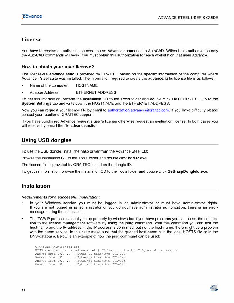
You have to receive an authorization code to use Advance-commands in AutoCAD. Without this authorization onlythe AutoCAD commands will work. You must obtain this authorization for each workstation that uses Advance.
How to obtain your user license?The license-file advance.aslic is provided by GRAITEC based on the specific information of the computer whereAdvance - Steel suite was installed. The information required to create the advance.aslic license file is as follows:
• Name of the computer HOSTNAME
• Adapter Address ETHERNET ADDRESS
To get this information, browse the installation CD to the Tools folder and double click LMTOOLS.EXE. Go to theSystem Settings tab and write down the HOSTNAME and the ETHERNET ADDRESS.
Now you can request your license file by email to [email protected]. If you have difficulty pleasecontact your reseller or GRAITEC support.
If you have purchased Advance request a user’s license otherwise request an evaluation license. In both cases youwill receive by e-mail the file advance.aslic.
Using USB dongles
To use the USB dongle, install the hasp driver from the Advance Steel CD:
Browse the installation CD to the Tools folder and double click hdd32.exe.
The license-file is provided by GRAITEC based on the dongle ID.
To get this information, browse the installation CD to the Tools folder and double click GetHaspDongleId.exe.
Installation
Requirements for a successful installation:• In your Windows session you must be logged in as administrator or must have administrator rights.
If you are not logged in as administrator or you do not have administrator authorization, there is an error-message during the installation.
• The TCP/IP protocol is usually setup properly by windows but if you have problems you can check the connec-tion to the license management software by using the ping command. With this command you can test thehost-name and the IP-address. If the IP-address is confirmed, but not the host-name, there might be a problemwith the name service. In this case make sure that the queried host-name is in the local HOSTS file or in theDNS-database. Below is an example of how the ping command can be used:
C:\>ping kh.meinnetz.netPING executed for kh.meinnetz.net [ IP 192. ... ] with 32 Bytes of information:Answer from 192. ... : Bytes=32 time<10ms TTL=128Answer from 192. ... : Bytes=32 time<10ms TTL=128Answer from 192. ... : Bytes=32 time<10ms TTL=128Answer from 192. ... : Bytes=32 time<10ms TTL=128

ADVANCE STEEL USER’S GUIDE
14
Please proceed with the installation as follows:
1. Close all active WINDOWS-applications
2. Insert the installation-CD into the CD-ROM drive
The setup-program starts automatically and the following dialog-box pops up.
To install Advance click Setup.
If the Setup didn‘t start automatically, please continue as follows:
The AutoPlay tool on your computer could be switched off and thus theinstallation does not start automatically. In this case, start the Advancesetup program with the command Run.To start a program using the Run command:– First click on Start and then on Run– Enter the path and the name of the program you want to start in the
Open field.Run dialog:
– In the Run dialog click on Browse to select the program Setup.exeon the CD in the folder shown above.
Start by clicking OK.

ADVANCE STEEL USER’S GUIDE
15
The installation will start.
3. Select the language you prefer
4. License Agreement
Read the license agreement. By clicking Yes you agree to the specified terms and the installation will continue.
5. User Information
Enter your name and your company name.
• Select “All users who use this computer” if Advance should be available for all users of this computer.
• Select “Current user only” if Advance should be available only for the current user.
To continue click Next.
ADVANCE STEEL USER’S GUIDE
16
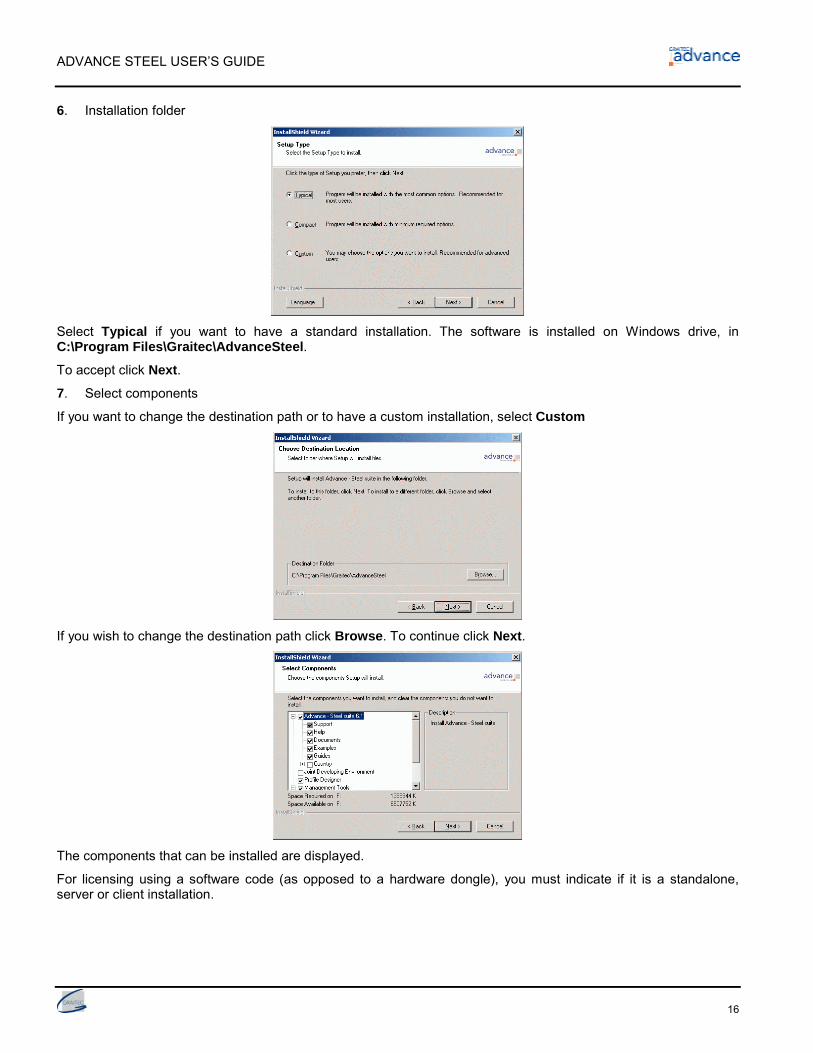
6. Installation folder
Select Typical if you want to have a standard installation. The software is installed on Windows drive, inC:\Program Files\Graitec\AdvanceSteel.
To accept click Next.
7. Select components
If you want to change the destination path or to have a custom installation, select Custom
If you wish to change the destination path click Browse. To continue click Next.
The components that can be installed are displayed.
For licensing using a software code (as opposed to a hardware dongle), you must indicate if it is a standalone,server or client installation.

ADVANCE STEEL USER’S GUIDE
17
StandaloneFor using a Standalone License select nothing for licensing.
Server and Client
If installing multiple licenses on a network and if your workstation is Server and Client at the same time, you have toinstall the License Management for both Server and Client. In the next step you will have to provide the name of themachine on which the license manager is installed in the Server option.

ADVANCE STEEL USER’S GUIDE
18
ServerShould you have more than one license, and the current installation is for the server, please install the Server Li-cense Management only. When installing the product as Client on other workstations you will have to set the nameof the server as being the name of the current computer.
ClientIf you have more than one License and the current installation is for a Client (not Server), please select only theClient option.
In this case the name of the server is required during the next installation step.
After the server name has been entered and the Next button clicked, the installation program searches for thespecified computer. This search might take some time.
ADVANCE STEEL USER’S GUIDE
19
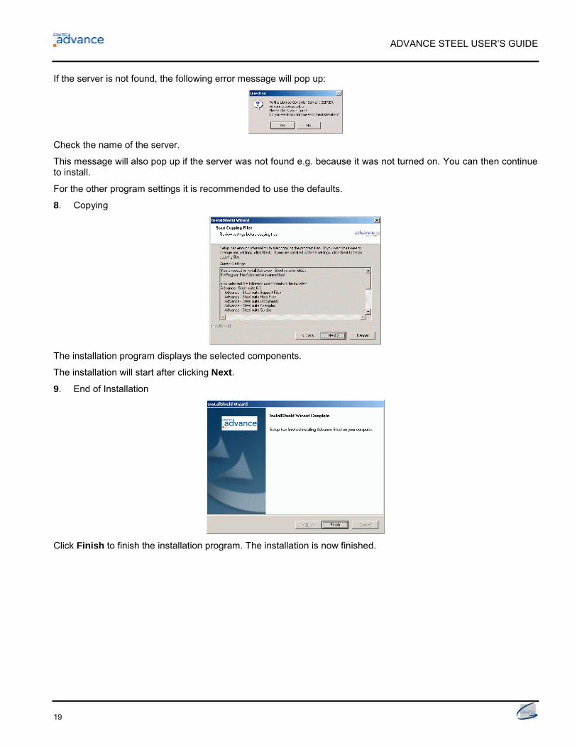
If the server is not found, the following error message will pop up:
Check the name of the server.
This message will also pop up if the server was not found e.g. because it was not turned on. You can then continueto install.
For the other program settings it is recommended to use the defaults.
8. Copying
The installation program displays the selected components.
The installation will start after clicking Next.
9. End of Installation
Click Finish to finish the installation program. The installation is now finished.

ADVANCE STEEL USER’S GUIDE
20
Authorize the software
In Advance vocabulary, “Authorizing your software”, means installing a license to use the software!
A license file Advance.aslic specific to the computer from which it was requested is sent to you by e-mail.
To authorize Advance software, follow the procedure described below:
To ask for a user's license or an evaluation license start Advance and choose the option “Request your user li-cense” and click on next.
An info window appears, click on Next after you have read the messages.
In this new window, enter all the required information for your license request and click on Next.
ADVANCE STEEL USER’S GUIDE
21
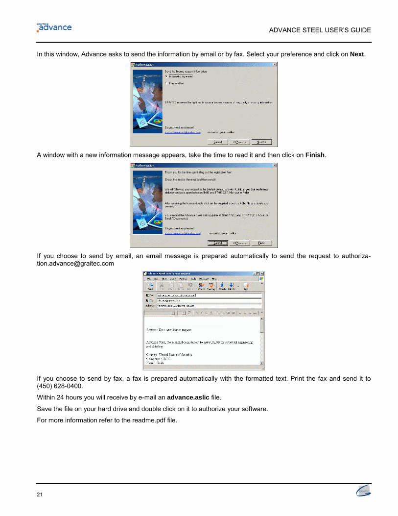
In this window, Advance asks to send the information by email or by fax. Select your preference and click on Next.
A window with a new information message appears, take the time to read it and then click on Finish.
If you choose to send by email, an email message is prepared automatically to send the request to [email protected]
If you choose to send by fax, a fax is prepared automatically with the formatted text. Print the fax and send it to(450) 628-0400.
Within 24 hours you will receive by e-mail an advance.aslic file.
Save the file on your hard drive and double click on it to authorize your software.
For more information refer to the readme.pdf file.

ADVANCE STEEL USER’S GUIDE
22
License Management
The application LMTools is installed with the license server software. With this application you can check whetherthe license server is active:
1. From the start-menu select the License Server icon in the group Graitec.
2. In the LMTools dialog-box you can enter the complete path to the license-file by Browse on the Serv-ice/License File tab. This file is under the directory where you have installed the license server.
3. Select the Server Diagnostics tab. In the next dialog-box, without other text input, click the button PerformDiagnostics.
4. Close the application
Installation for existing AdvanceSteel users
Before installing the AdvanceSteel new version, please backup your work (databases, symbols, prototypes anddrawings you made with the previous AdvanceSteel version).
Now you can run the setup.
The installation is made in the same folder, and the files from the old version are updated. Backups of the data-bases you had in the previous version automatically created in a folder called Oldddddddtttttt (the folder namecontains the date and time of the AdvanceSteel installation).
Settings are made automatically for the Convert module of the Management Tools and your AstorAddIn.mdb file isconverted to the current version and structure, but you will not lose your customizations from the previous version.
You are able to Convert your settings from the old version into the new version using the Convert module of theManagement Tools.

ADVANCE STEEL USER’S GUIDE
23
If you did not have AdvanceSteel installed on the computer, the installation of the new AdvanceSteel will continuenormally. You can always convert settings from the previous version to the new databases if you have some data-bases saved in a folder. In the Convert module, simply specify the old database name.
Converting database (Merging)
Old databases can be converted to new databases using the Management Tool. This might be required on a newrevision of Advance Steel or if the users want to exchange information.
Note: Only the database from a previous version can be converted. Advance Steel backups all your old data-bases, creates DSN for each of them and enables the ODBC option for the created datasources.
Having a column with author information is a prerequisite for converting databases.
Note: When converting, not all tables (libraries) are converted into the new release. The tables (libraries) can-not be converted if the structure of the tables (libraries) was changed.
Save your databases before converting them.
Start the Management Tool. The window Convert database will open.
Click the Convert database button if the Convert database window did not appear.
In the Convert database window click the Options button. In the Options window you can control the settings.

ADVANCE STEEL USER’S GUIDE
24
Display tables (libraries)Here you can define what should be displayed when the tables (libraries) have been analyzed, whether the differenttables (libraries) or identical tables (libraries), in the current release and/or the previous release (to be converted).
Use defaultsHere you can select whether the defaults of the previous release (to be converted) or of the new release should beused.
Use preferred sizes (for objects in library)Here you can select whether the preferred sizes of the previous release (to be converted) or of the new releaseshould be used.
In the Convert database window you can select the databases you want to Convert in two different ways:
One way is by the ODBC-information source
• The other way is directly by the database (*.mdb) by giving the file-name in the “Merge what” field. For exam-ple, search for the database AstorBase.mdb.
Click Continue after selecting the database and the tables (libraries) in the databases are compared. The Com-parison result window then pops up.

ADVANCE STEEL USER’S GUIDE
25
Under “Groups” the Advance Steel new databases are listed. Open e.g. the list under “Base” and a window with thefollowing content appears:
The icons in front of the table names indicate the comparison result :
Table is identical
Table can be automatically converted
Table cannot be converted, because table structure has been modified.
Tables (libraries) available only in current release.
Only tables (libraries) with status set to “Automatic” can be converted.
Tables (libraries) with a specific status are selected by a mouse right click in either side of the window. From themouse pop-up menu you can click or de-click selection criteria (different, identical or in current / previous version).
If you select Filter, another window will pop up where you can select tables (libraries) to be displayed.
The code letters in the right window or in the Filter window have the following meaning:
I Table is in source database, but not in destination databaseC Source database contains columns not available in destination databaseE Source and destination databases have different columns with identical values in the fieldsA The entries in the source and destination database are identical, but have different authorsS Table contains fields with linksX Tables (libraries) have different structures

ADVANCE STEEL USER’S GUIDE
26
If you do not want to convert all the tables (libraries) (that can be automatically converted) in the new database,you can de-click conversion (Converting – Off).
If you want to convert only some information records from a selected table click the manual converting from thepop up menu with the radio buttons in the right panel of the window.
The status is changed from “Automatic” to:
Converting – Off
Converting Manually
After selecting the conversion method for all convertible tables (libraries), click on Convert and the process willstart. Every element to be converted manually will ask for validation.
When the converting is done all windows of the Convert database tool must be closed.
Support
GRAITEC has hotline and e-mail support for Advance.
Support by telephone
Please ask your dealer or closest GRAITEC office for the appropriate telephone-number.
The 3D-Model
In this chapter:■ Elements of the 3D-model■ 3D-Modelling workflow

ADVANCE STEEL USER’S GUIDE
28
Elements of the 3D-model
The Advance 3D model is built from elements such as beams, plates, structural elements, bolts, welds, featuresjoints. Once the model is finished, checked and numbered, all output like structured BOM, NC data, general ar-rangement and detail drawings could be completed.
3D-Modelling Numbering Drawings
BOM‘s / NC-Information
Beam & PlateThe 3D-model is built mainly from Advance basic objects:
• Beams, created as section classes, simple sections, compound sections, curved sections
• Plates as rectangular plates or as polygon plates with any contour.
Beams and plates are created directly in the model and are displayed in the ‘wireframe’ mode by default.
Figure 1: Advance Beam and Plate (standard presentation)
Figure 2: Compound section and curved beam, shown in the AutoCAD 'Hidden' presentation
ADVANCE STEEL USER’S GUIDE
29
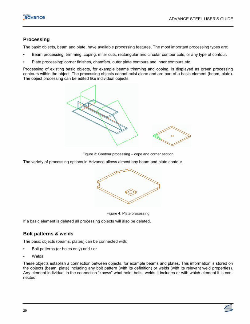
ProcessingThe basic objects, beam and plate, have available processing features. The most important processing types are:
• Beam processing: trimming, coping, miter cuts, rectangular and circular contour cuts, or any type of contour.
• Plate processing: corner finishes, chamfers, outer plate contours and inner contours etc.
Processing of existing basic objects, for example beams trimming and coping, is displayed as green processingcontours within the object. The processing objects cannot exist alone and are part of a basic element (beam, plate).The object processing can be edited like individual objects.
Figure 3: Contour processing – cope and corner section
The variety of processing options in Advance allows almost any beam and plate contour.
Figure 4: Plate processing
If a basic element is deleted all processing objects will also be deleted.
Bolt patterns & weldsThe basic objects (beams, plates) can be connected with:
• Bolt patterns (or holes only) and / or
• Welds.
These objects establish a connection between objects, for example beams and plates. This information is stored onthe objects (beam, plate) including any bolt pattern (with its definition) or welds (with its relevant weld properties).Any element individual in the connection “knows” what hole, bolts, welds it includes or with which element it is con-nected.

ADVANCE STEEL USER’S GUIDE
30
A bolt pattern can describe one or several bolts, which are automatically created in any plane together with the ap-propriate holes.
Figure 5: Bolt Pattern, Weld Point
Changes in the bolt pattern will also automatically update the holes.
The tools for creating bolt patterns can be used for bolts in addition to:
• Holes, slotted holes, countersunk holes, blind holes, threaded holes and punch marks
• Shear studs
The above are all created with their respective properties or definitions.
It is also possible to create the above various hole types as part of a bolt object and a separate hole object.
Weld points are displayed as crosses in the model.
JointsAnother option for connecting the basic elements is the Advance joints. Joints are complex elements that consist ofbasic elements and dependent elements that are controlled by a construction rule.
All elements individual in the joint, including their properties and processing objects, is held together and repre-sented as a gray box connection object.
All connection objects and definitions are included in the gray box.
Example: Haunch connection
A portal column and rafter is connected with an intelligent rule-based joint. For example this is a haunchconnection, including plates, stiffeners and bolts.
Figure 6: Connection object (gray box)

ADVANCE STEEL USER’S GUIDE
31
The following joints are included in Advance:
• Connections for North America: end plates, clip angle connections, base plate, flat bracings, HSS bracings
• Frame corners
• Gable wall connections and pin-ended columns connections
• Ridge connections and splices
• Platform connections, end plates, web connections and shear plates
• Gusset plates and diagonal bracing (HSS and Flat)
• Base plates and stiffeners
• Tube connections
• Turnbuckle bracing
• Pylon construction connections.
And on the alternative UK Joints toolbar, the following additional flyouts can be found:
• UK Hot Rolled Joints
• UK Cold Rolled Joints
The rules and the structure of joints are stored in Access-tables (libraries). Adjustment of these rules to user re-quirements (or creation of new rules) is possible with knowledge of Advance’s macro programming language.
In addition to the joints provided in the standard Advance package, interactive (also called manual) joints can becreated, stored and re-used.
Structural elementsStructural elements is an intelligent group of basic elements and dependent elements classified as follows: symmet-rical goal post frames and Portal frames, single-span bracings, purlin positions, various stairs, pylons, joists andhalf truss.
These elements are created as a group of several basic elements in relationship to each other. Elements and theirrelationships are held together and stored with a structural frame. The structural frame is displayed in the model asa white continuous line (showed below).
Example: Portal frame
A Portal frame consists of four sections: two grouped columns and two grouped rafters, connected by astructural element macro.
Figure 7: Portal Frame

ADVANCE STEEL USER’S GUIDE
32
All changes to one element affect the entire group. If a rafter section is changed then the second rafter section willalso be changed. The column sections of the frame behave in the same way. A change in the total height or thecolumn height affects the entire structural element.
Auxiliary objectsAuxiliary objects are
• Grid axes or
• Level symbols
These don’t belong directly to the frame but support the construction process. Nevertheless, they are importantelements.
Example: Building grid
A building grid that corresponds to the dimensions of the construction forms the basis of the 3D-Modelingand helps with orientation in three-dimensional space.
Figure 8: Building grid with portal frame
Special partsObjects that are not Advance standard objects can be created as special parts. When Advance creates drawingsand bills of material with special parts they are handled like standard objects. If these objects (special parts) shouldappear in the bill of material, they must be provided with Advance properties. Possible Advance information that canbe attached is:
• Weight
• Material
• Coating
• Name
• Commodity
• Lot/Phase
• Part number (single part and assembly)
• Model Role
• Other

ADVANCE STEEL USER’S GUIDE
33
3D-Modelling workflow
Create the building grid
Create beams, plates, structural elements
Edit Beams / Plates (processes)
Add Advance elements with joints / interactive connections
Add other interconnecting members
Controls / Checks for collisions and Measurements


Advance Interface
In this chapter:■ Advance toolbars / menus■ Using Advance■ Create Advance objects

ADVANCE STEEL USER’S GUIDE
36
Starting the program / working environment
Start AutoCAD / Advance by double-clicking on the Advance Steel Icon on your desktop.
AutoCAD and Advance are started and the user interface appears.
The template drawing ASTemplate.dwt is automatically called when starting AutoCAD / Advance. It contains im-portant defaults like current coordinate system, the orientation, object snap settings, layer assignment and colordefinitions so you can immediately begin Modeling.
First you are in a three-dimensional isometric view, in which the User Coordinate System (UCS) is active and cur-rently set to the World Coordinate System (WCS). All coordinate entries refer to the UCS.
• Save your work with an appropriate name in an AutoCAD format DWG. Use File in the upper left corner of thescreen. Each project should be saved in its own folder for easier file management.
Among other features other template drawings and files for certain drawing formats are delivered with Ad-vance.
Advance toolbars / menus
All Advance tools are grouped by type and are available in toolbars, positioned in a space saving manner in theAutoCAD environment.
To keep the interface clear and make each command easy to find, only two Advance toolbars appear when firststarting AutoCAD / Advance; the Standard and the Advance Steel toolbars.
They contain commands and sub-toolbars in the form of flyouts. Flyouts open by clicking and contain other Advancecommand buttons.
The Advance Steel toolbar icons call the Advance main toolbars that contain logically grouped Advance tools, ob-jects and elements. When called-up these main toolbars replace each other (with exception of the main toolbarDesign assistance), so the model workspace remains uncluttered with plenty of space.
Figure 9: Advance Advance Steel – toolbar
If for example you open the Advance main toolbar Create objects (1. Button from left), through the Advance Steeltoolbar, it remains on the display until another main toolbar, for example Joints (2. Button from left), is opened. Thetoolbar Joints replaces the toolbar previously opened and remains open until another toolbar is called.

ADVANCE STEEL USER’S GUIDE
37
...
...
Figure 10: Advance Standard – toolbar
The Standard toolbar includes tools for building, displaying, changing and marking Advance elements, the AdvanceDocument Manager, drawing layout and other help tools. It also contains often-used AutoCAD-tools for use withAdvance.
Flyout CommandCREATE OBJECTS
Command
Flyout CommandJOINTS
Command
Flyout CommandSTAIRS & RAILINGS
Command
Flyout CommandLISTING & CHECKING
Command
Flyout CommandNUMBERING, DRAWING
Command
Flyout CommandSPECIAL SECTIONS
Command
Flyout CommandADDITIONAL TOOLS
Command
Flyout CommandDESIGN ASSISTANCE
Command
Flyout Command
AD
VAN
CE
STEE
L
STANDARDCommand
Figure 11: Arrangement of the Advance toolbars

ADVANCE STEEL USER’S GUIDE
38
Figure 12: Advance Create objects
The toolbar Create objects contains commands for grid, structural elements, beams, beam processing, plates,plate processing, construction systems, bolts, holes, shear studs, welds, and for the display and modification ofconnections.
Figure 13: Advance Joints toolbar
The Joints toolbar contains all joints, located by the type of individual elements, and the corresponding commandsto the handling of these joints and connection objects.
The toolbars reviewed up until now are essential to create a three-dimensional model. The Design assistancetoolbar can also be used if required.
Figure 14: Advance Stairs & Railings toolbar
The Stairs & Railings toolbar contains commands for creating stairs, railings, ladders and specific joints (stairfooting, end plate with cope, shear plate, platform splice, angle connection, railing anchorage, bolted end plate).
Figure 15: Design assistance toolbar
In the Design assistance toolbar you can access important checking tools (collisions in the model, checking data-base), which are required during construction and also found in other toolbars. Special Advance commands to copy,rotate and mirror connections are included. This toolbar accelerates the construction-work with often-used com-mands all in one place.
Figure 16: Advance Listing & checking toolbar
The Listing & checking toolbar includes commands for structured BOM, collision test, save with proxy-graphics,Advance Audit checking, steel construction technical checking, special parts, and update defaults. This toolbardoes not have commands for the construction environment but is used for managing / checking the model and forcommunication with other programs.
Figure 17: Advance Numbering, drawing toolbar
The Numbering, drawing toolbar contains all commands concerning numbering and drawing creation, the auto-matic drawing creation with processes and the Document Manager. The predefined drawing styles as the menu aredifferent for each installation.

ADVANCE STEEL USER’S GUIDE
39
Figure 18: Advance User sections toolbar
The User sections toolbar includes all required commands for creating custom sections that are not standard sec-tion shapes (can be added directly in tables (libraries)).
Figure 19: Advance Bonus toolbar
The Bonus toolbar contains applications being developed for an upcoming release thus is not yet documented.
Using Advance
The main toolbar contains buttons that are tools or call other flyout-menus. The Flyout-Menus buttons have ablack triangle in the lower right corner. These buttons automatically open when the cursor is over them.
Example: Opening grid commands
• Call the Advance main toolbar Create objects by the Advance Steel-toolbar.
Create objects• Place the cursor over the first button of the Advance main toolbar Create objects.
• The Flyout Sub – Axis grid pops up.
Figure 20: Accessing Sub – Axis grid flyout
Instead of individually calling flyouts (that shut independently) several menus can be called by the View field of theAutoCAD menu-bar. If more tools from the sub-toolbar are required for the construction of a grid from the Toolbarstab you can for example pick menu group AstBasic and Sub – Axis grid.
Figure 21: Sub-Axis grid toolbar
Start an Advance command by clicking a toolbar button. The command appears in the AutoCAD command line atthe bottom of the screen.

ADVANCE STEEL USER’S GUIDE
40
Other important tools for using Advance• You can abort commands by using the Esc –key.
• The current command and prompts are displayed in the command line window at the bottom of the screen.You can open and close the command line window with the F2 –key.
• The right mouse click is like the Return key of your keyboard. (Depending to your AutoCAD system settings)
• If you hover the cursor over a toolbar button its tooltip will appear.
Undo• The Undo command from the AutoCAD Standard toolbar cancels one or several executed commands.
• With the Match properties command from the AutoCAD Standard toolbar you can copy properties from oneobject to another. You can select from the given list which properties are transferred.
Match properties
Create Advance objects
Advance objects are created in 3D-space using corresponding program tools. Their orientation depends on thecurrent UCS (User Coordinate System).
When you create points by digitizing or using coordinates, you determine the position and orientation of the object inspace. A dialog-box will open in which different settings (geometric sizes etc.) and if necessary drawing styles canbe changed. (E.g.: dimension/label on the drawings).
The settings in the dialog-box are sorted in different tabs that vary according to the object-type.
Figure 22: Example: Plate dialog-box
When a dialog box field (dimension, position, etc.) is changed the model updates instantly (= model preview):
• By clicking into the next field,
• By closing the window (click on the X in the right upper corner),
• By using the tab-key to get into the next field or
• By using the enter-key to select the value in the enter field.

ADVANCE STEEL USER’S GUIDE
41
Initial settings of an object (for example a plate) are stored and can always be recalled and updated using the samedialog-box.
Advance will recall your last dialog-box values and preferences the next time you use the same tool. After restartingAutoCAD / Advance, the dialog-boxes use the default settings.
You can change these default settings in the system menu of the dialog-box (right click on the header line of thedialog-box). In this system menu, the dialog-box entries become the defaults at startup.
Object propertiesAll created objects have default Properties that can be changed; in the Advance Properties dialog-box that auto-matically opens after creating the object.
Figure 23: Beam – properties dialog-box
The object properties are classified as following:
• Geometric Properties (position in the model, shape)
They are set on creation and can be changed afterwards using standard AutoCAD commands (move, rotate,copy etc.) and grips.
• AutoCAD specific properties
Set in the AutoCAD-property dialog box. You can change these properties in the AutoCAD command Proper-ties.
• Technical properties are:
Properties for the representation on-screen (for example: Representation of a beam with or without processing)and non-graphic properties (material, name etc.). This information goes in the structured BOM’s and drawings.
Figure 24: Beam “features” and “standard” representation

ADVANCE STEEL USER’S GUIDE
42
Figure 25: Non-graphic properties for the structured BOM
To open an object dialog box double click on the object.
Another way to access the properties is to select the object(s) and with a right mouse click select Advance proper-ties from the menu. (Depending on the AutoCAD system settings)
LayerAdvance objects are by default created on the active Layer but can also be placed automatically on specific layerswith different properties. This feature is set in the DWG drawing template file ASTemplate.dwt using the AdvanceManagement Tool.
Advance objects are displayed by default in the following colors:
Object ColorBuilding grid GreenBeam YellowPlates Magenta (pink)Bolts Cyan (turquoise)

Creating a 3D-Model
In this chapter:■ Create building grid■ Creating a beam■ Create plates■ Coordinate systems■ Beam processing■ Plate processing■ Change Advance objects■ Advance command properties■ Welds■ Connections■ Working methods I■ Structural elements■ Joints and connection objects■ Special parts, special sections■ User Sections

ADVANCE STEEL USER’S GUIDE
44
Create building grid
The Advance auxiliary object “building grid“ makes it easier to place Advance objects within a construction design.
A building grid consists of axes in the X- and Y- directions. The grids facilitate placing of the construction elementsand orientation in the 3D view. Placing a building grid is the first step of 3D-modelling in Advance.
Figure 26: Advance building grid
A building grid is created in the X/Y-plane of the current coordinate system and consists of two independent axisgroups.
Picking three points can create curved single axis.
A building grid can be copied, for example upwards, several times if needed. For better recognition the grids canhave different labels (A, A‘, A‘‘) on the various planes with a different color on a new AutoCAD layers (recom-mended).
Figure 27: Building grid
Example: Create an axis group by setting the distance between axis
• Start AutoCAD / Advance with the template file ASTemplate.dwt.
• Click on the button in the toolbar (Flyout) Sub – Axis grid.
Flyout Sub – Axis grid
Figure 28: Sub – Axis grid toolbar

ADVANCE STEEL USER’S GUIDE
45
• Give the starting point of the first grid line as (0,0,0) (please give end points of the grid line. starting point:_0,0,0 Return),
• Then give the end point of the grid line by dragging the mouse pointer (with Ortho-mode on, F8 on yourkeyboard), in the X-direction and put 26’-8” (end point 26’-8” Return).
• Determine the direction of the axis group by picking a point in the Y-direction on the screen (orientation ofthe group: Return).
• Now enter the distance between axes of 6’-8” for each, until the AutoCAD command line has a total value of26’-8” and then close the command by clicking Return twice. The axes group in the X-direction is created,and the dialog-box Axes, parallel will open.
Figure 29: Building grid: axes in x-direction
Figure 30: Dialog-box Axes, parallel
• In the Total tab of the dialog-box, the length property (distance between the first and the last axis) andwidth (length of the axes) can be changed. The axes are automatically labeled with numbers or letters.
• Close the dialog-box by clicking on the cross in the upper right corner.
• To create a complete building grid, carry out the same steps for an axes group in the Y-direction.
To change the axes group, identify a group and choose the option Advance Properties in the menu.
When clicking the Group tab, the color of the selected group is changed to red. The number of single axes or theirdistance within the total length can be indicated.
The Single axis tab enables individual axis labeling (if automatic labeling is turned off in the Total tab). The se-lected axis is displayed in red. You can add an axis to the right or left of a main axis and chose a label using themain axis name with a suffix and a prefix.
The grid axes can be hidden by the Representation type tab or switched to single axis presentation.
• To create a complete grid with a group of axis in both X- and Y-directions, use the tool “Building grid”. This
building grid can be created as a standard grid by clicking the button and right clicking twice with themouse or by giving specific coordinates of the origin point and the second diagonally opposite point.
In both cases, you can always modify the grid size, division and labeling (Advance Properties by a double click).Since two axis grids are created in the course of this command, no dialog-box appears.

ADVANCE STEEL USER’S GUIDE
46
The toolbar Sub – Axis grid contains the following other tools for creating and designing building grids:
Button Function
Create grids by individual groups with 4 axes
Create grid groups with distances
Create one axis in a group
Create axis from a group
Create a group of axes
Cut a group
Extend a group
Create a curved single axis
Create a level symbol
More detailed information on individual tools, presentation types, snaps, grips and object coordinate systems can befound in the axis grid chapter of the Advance online Help.
Creating a beam
In Advance, a variety of beams are preset for creation such as rolled I sections, channels, angles, T-sections, tubes,Zeds, flats, round bar, square bar, square/rectangular hollow sections, cold rolled sections, purlin sections and othersection classes (toolbar Sub – Section classes). All types are available from the named sections in each case.Compound and welded sections can be also created. There are various types of compound and welded memberavailable in two flyouts: Sub – Welded sections and Sub – Compound sections.
The named beams can be created as curved or poly beams.
Additionally, individual sections can be set as special sections (see chapter Special parts, special sections).
For the beam creation, five flyouts are available in the Create objects toolbar for the following tools:
Figure 31: Buttons for creating the beams
• Creation of beams – section classes (flyout)
• Creation/ Explode of compound sections (flyout)
• Create sections from various cold rolled systems (e.g. Canam Manac, Canfer etc.)
• Creation of beams (flyout)
• Creation of welded beams (flyout)
The buttons contain Flyouts, which are shown in the chapter’s Straight beams, Compound sections and Construc-tion systems.

ADVANCE STEEL USER’S GUIDE
47
Straight beamsStraight beams can be created in the Advance 3D-model relative to the current user coordinate system (UCS) byentering one starting point and one end point.
The current user coordinate system (UCS) determines the position of the sections' main axes: the web of a beamruns in the Z-direction of the UCS – or in other words, the ‘top’ of the section is in the Z-direction.
Example: Creation of a straight beam HEA 400 x 13’-4’’ long
Figure 32: Beam HEA 400
• Click a suitable UCS, see above figure for example.
Figure 33: Advance toolbar (Flyout) Sub – Section Classes
• Choose the Beam button of the flyout Sub – Section Classes from the main-toolbar Create objects.
• Input a starting point on (0,0,0).
• Move the mouse pointer upwards in the Y-direction (the setting Ortho causes an exact orientation entry)and type the value 13’-4’’. A standard I-section is created.
• The dialog-box Beam pops up. First choose the section class (HEA), followed by the section (HEA 400).
For required beam length and placement you can use three different object axes types:
• The insertion axis (system line) is an axis that has two points and forms the relation of a beam.
• Reference axes are important specific axes for sections such as edge lines or center lines.
• The gravity axis is the line of the cross-section areas of the center of gravity. Not all sections have these(for example C-shaped profiles).
Figure 34: Axes of a beam

ADVANCE STEEL USER’S GUIDE
48
The standard insertion axis (system line) of a beam lies in the center of gravity. The beam can be moved or rotatedrelative to the insertion axis or reference axis by changing the values in the Position and Offset tab of the Beamdialog-box.
A variety of other properties such as entries for drawings style (= the type of dimensions and labels used in theautomatic detailing by processes), material etc or for behavior, used when considering identification of identicalparts, collision test and creation of BOM’s.
During drawing creation the Model role, set in the Note tab will influence the output. An object set as a column isdimensioned and labeled differently than if it is set as a beam by the automatic detailing process.
The Properties-1 tab contains information for beams such as weight and coating surface area, whereas the Prop-erties-2 tab contains section values such as flange thickness, web thickness and height etc.
Compound sectionsTwo or four sections, as a combined section (named Compound sections), are created at a system line. The sec-tions are handled as a single section so that a trim will affect all sections.
To create Compound sections you can use the flyout from the Create objects toolbar.
Figure 35: Sub – Compound sections toolbar (Flyout)
Compound sections are created like simple sections by entering a start point and an end point according to thecurrent coordinate system.
Figure 36: Compound sections
The properties in the dialog-box such as position, material, drawing-style or representation type corresponds tothose of the simple sections.
In the additional tab Shape, the distances between the single profiles in X- and Y-directions can be changed if re-quired.
The last button of the toolbar Sub – Compound sections separates the assembly into single beams. Each beamthen gets its own system line. The single axes are overlapped and each beam has an offset value.
Before creating joints compound sections must be separated into single beams because joints can only be at-tached to single beams.
Before creating BOM’s and drawings compound sections must be separated into single beams otherwise they aretreated as one beam and this would result in an incorrect quantity of beams in the BOM.

ADVANCE STEEL USER’S GUIDE
49
Curved beamsThe previously listed section classes can also be created as curved beams. To create a curved beam, click thecorresponding button and give a starting point and an end point for the length of the section, followed by one circlepoint for the radius.
As in the case of straight beams, the current coordinate system determines the position of the main axes of thebeam. The curved beam web runs in the Z-direction of the current UCS (the ‘top’ of the section is in the Z-direction).If required, the created curved beam can immediately be rotated through 90° about its system line.
Example: Creation of a curved beam HEA 240 between two columns (straight beams)
Figure 37: Curved beams
• Choose a user coordinate system like illustration above for example.
• Click on the button from the Sub – Beams flyout of the main toolbar Create objects. Use the uppersystem line end points of the columns as the start and end point.
• With a circle point define the radius of the curved beam. Pay attention to define the circle point in the X/Y-plane of the coordinate system. Alternatively, pick a point at any radius and then specify the required radiusthrough the dialog box on the Curved tab. It is very important that the required radius is set while the sys-tem line is at center point (center of gravity). The system line can then be set on one edge and the radiuspreviously entered will then correspond to that edge. Note that the radius in the dialog will then changevalue since it displays the radius to the center of the section!
• The curved beam in our example must be rotated 90°. Make this change in the Position tab of the Beamdialog-box.
All other beam properties are the same as straight beams. On the Curved tab, in which the radius is set, there is atolerance field to set the circle representation accuracy.

ADVANCE STEEL USER’S GUIDE
50
Poly beamsThe section classes listed in the Straight Beam chapter can also be created as poly beams.
To create poly beams a polyline must be created. Any 2D or 3D polyline can be converted to a poly beam.
The position of the beam is independent from the coordinate system since the beam position is determined by theposition of the polyline.
Example: Creation of a poly beam
Figure 38: 2D poly beam
• Draw an AutoCAD polyline in a suitable user coordinate system.
• Click the button from the Sub – Beams flyout of the main toolbar Create objects.
• Select the polyline.
• Confirm the selection with Return.
• Now you can keep the polyline or to delete it.
• Type Y for Yes (or N for No) and finish with Return.
All other beam properties are like straight beams.
Any line or arc can be converted to a beam using the tool “Beam, polyline”.
Folded profileFolded profiles can be created from the Sub – Beams flyout of the Create objects toolbar. You can define thecross section directly inside the model by specifying the points (point by point) in the current UCS or by selecting anAutoCAD polyline. The folded plate can be an open or closed section.
Example: Creation of a closed folded profile in the current UCS
Figure 39: Closed folded profile (Z was vertical when created)

ADVANCE STEEL USER’S GUIDE
51
• Place a coordinate system with the X/Y-plane in the required plate plane.
• Click the button from the Sub – Beams flyout of the main toolbar Create objects.
• Select the corner points one after another.
• End with Return.
• Click the start point of the system line.
• Click the end point of the system line.
• The folded profile is created.
You can also create a folded profile by selecting an existing polyline.
The folded profile properties can be set and changed in the dialog-box. The thickness and the positioning can beset in the Section tab of the properties dialog-box. The radius of each corner can also be changed.
Figure 40: Section properties for the folded profile
Folded profiles have a specific representation type: “Exact (possible to modify the section)”
Figure 41: Folded profile – Representation type
With the representation type set to “Exact (possible to modify the section)”, you can modify the shape of the foldedplate by moving its grips.
Figure 42: Folded profile – grip points
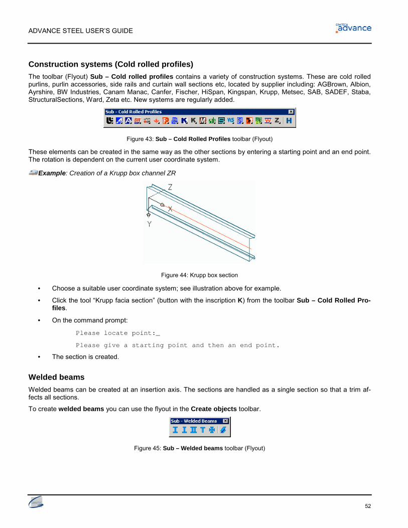
ADVANCE STEEL USER’S GUIDE
52
Construction systems (Cold rolled profiles)The toolbar (Flyout) Sub – Cold rolled profiles contains a variety of construction systems. These are cold rolledpurlins, purlin accessories, side rails and curtain wall sections etc, located by supplier including: AGBrown, Albion,Ayrshire, BW Industries, Canam Manac, Canfer, Fischer, HiSpan, Kingspan, Krupp, Metsec, SAB, SADEF, Staba,StructuralSections, Ward, Zeta etc. New systems are regularly added.
Figure 43: Sub – Cold Rolled Profiles toolbar (Flyout)
These elements can be created in the same way as the other sections by entering a starting point and an end point.The rotation is dependent on the current user coordinate system.
Example: Creation of a Krupp box channel ZR
Figure 44: Krupp box section
• Choose a suitable user coordinate system; see illustration above for example.
• Click the tool “Krupp facia section” (button with the inscription K) from the toolbar Sub – Cold Rolled Pro-files.
• On the command prompt:
Please locate point:_
Please give a starting point and then an end point.
• The section is created.
Welded beamsWelded beams can be created at an insertion axis. The sections are handled as a single section so that a trim af-fects all sections.
To create welded beams you can use the flyout in the Create objects toolbar.
Figure 45: Sub – Welded beams toolbar (Flyout)

ADVANCE STEEL USER’S GUIDE
53
Welded beams are created like simple sections by entering a starting point and an end point in the current coordi-nate system.
Figure 46: Welded beam - Hollow
You can control the section class and section of each individual element in the welded beam Section tab of theproperties dialog box. The Welds tab configures the welds between the different elements.
You can store your welded beams in a library using Save and Save as.
Welded beams have two specific representation types:
• Complete: when you cut the welded beam, the entire section is cut.
• Separated: only the picked element of the welded beam is cut.
Figure 47: Compound beam properties – Representation type
Create plates
Plates can be created in Advance in almost any shapes and sizes in any plane. The Advance default plate thick-ness is controlled by the Management Tools.
The tools to create plates are in the toolbars (Flyouts) Sub – Plate and Sub – Folded Plates of the Advance maintoolbar Create objects.
Figure 48: Flyouts Sub – Plate and Sub – Folded Plates
Tools includes:
• Rectangular plates
• Polygon plates
• Gusset plates
• Split and merge existing plates.

ADVANCE STEEL USER’S GUIDE
54
3D folded plate of any shape can be created, by joining different plates together.
Rectangular plates are created by a center point, by two diagonally opposite corner points or three points defining aplane.
For the creation of polygon plates, you can pick the corner points directly or create a poly line that doesn’t need tobe closed.
Polygon plates can be resized.
Any plate can be converted to a polyline and vice versa. The re-converted plate retains its initial properties.
Rectangular plates can be converted into polygon plates but the reverse is not possible.
Rectangular plateThe rectangular plates are placed in the X/Y-plane of the current coordinate system.
Figure 49: Rectangle plate, center
Example: Creation of a rectangular plate by the center point
• Place a coordinate system with the X/Y-plane in the required plate plane.
• Click the button from the flyout Sub – Plate of the main toolbar Create objects.
• Give a center point by digitizing with either an object snap or entering coordinates.
• End with Return. The plate is created with default length, width and height.
In the Plate dialog box that opens automatically after creation, you can define or change a variety of plate proper-ties such as the plate size under the Shape tab (length X, width Y).
Figure 50: Plate dialog-box, Shape tab
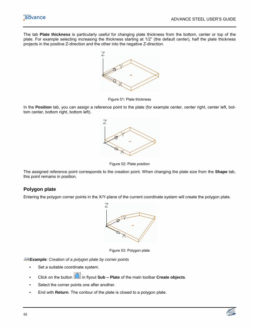
ADVANCE STEEL USER’S GUIDE
55
The tab Plate thickness is particularly useful for changing plate thickness from the bottom, center or top of theplate. For example selecting increasing the thickness starting at 1/2” (the default center), half the plate thicknessprojects in the positive Z-direction and the other into the negative Z-direction.
Figure 51: Plate thickness
In the Position tab, you can assign a reference point to the plate (for example center, center right, center left, bot-tom center, bottom right, bottom left).
Figure 52: Plate position
The assigned reference point corresponds to the creation point. When changing the plate size from the Shape tab,this point remains in position.
Polygon plateEntering the polygon corner points in the X/Y-plane of the current coordinate system will create the polygon plate.
Figure 53: Polygon plate
Example: Creation of a polygon plate by corner points
• Set a suitable coordinate system.
• Click on the button in flyout Sub – Plate of the main toolbar Create objects.
• Select the corner points one after another.
• End with Return. The contour of the plate is closed to a polygon plate.

ADVANCE STEEL USER’S GUIDE
56
The properties of the plate can be set and changed in the dialog-box; no dimensions are available in the X/Y-planefor this plate type.
Another way to create a polygon plate is to transform an existing polyline, which need not be closed, into a plate.
In this case, the position of the plate is independent from the coordinate system since the plate position is deter-mined by the position of the polyline.
Figure 54: Polyline and created plate
• Click the button “Plate on polyline” flyout Sub – Plate from the main toolbar Create objects.
• Select the required polyline and finish with Return.
Any plate can be converted to a polyline.
• Click the button “Plate to polyline” flyout Sub – Plate from the main toolbar Create objects.
• Select the plate and click Return. Now you can keep the plate or delete it.
• Type Y for Yes (or N for No) and finish with Return.
• The plate is converted to a polyline and deleted.
The resulting polyline can be modified and converted back to a plate. The plate is created with its initial properties.
Gusset platesUsing the flyout Sub – Plate the gusset plates can be placed in the current coordinate system plane on existingbracing members with predefined bolts (bolt patterns).
Two points on a straight line will define the guiding edge, which is kept when creating the gusset plate. After selecting thepoints, identify a bracing member and its attached bolt pattern and if required other bracing members and bolt patterns.
Example: Create a gusset plate on a guiding edge
Figure 55: Gusset plate, guiding edge by point 1 and 2
• Place a UCS in the plane of the gusset plate
• Click on the button in the flyout Sub – Plate of the main toolbar Create objects.
• Determine the guiding edge with two points (1 and 2).
• Identify a bracing member and its attached bolt pattern, then the second bracing member and the bolt pattern.
• End with Return.
All created plates can be moved and/or changed with AutoCAD and Advance commands, see chapter Plate proc-essing.

ADVANCE STEEL USER’S GUIDE
57
Split / merge - platesExisting Advance plates can be divided at a polyline or at two points into two or more plates. Any plate processing(e.g.: contours etc.) is kept.
Example: Rectangular plate divided on polylines
Figure 56: Plate divides on polyline(s)
• First create the polyline(s) on the existing plate at the dividing position.
• To divide the plate, choose the button in the flyout Sub – Plate of the main toolbar Create objects.
• Identify the plate / plates to be divided (identify objects...), Return.
• Select one or more polylines, Return,
• Enter a value for the required gap between the plates and close the command with Return.
To merge plates, start the tool “Merge plates” from the flyout Sub – Plate, identify the plates to be merged andclose the command with Return.
Shrink/enlarge polygon platePolygon plates can be shrunk or enlarged. One or more plates must be identified and a dimension entered. A nega-tive value shrinks the plate, while a positive value enlarges the plate.
Example: Shrinking a plate
Figure 57: Polygon plate before and after shrinking
• To shrink a polygon plate, click the button in the flyout Sub – Plate of the main toolbar Create objects.
• Identify the plate (one or more) to be shrunk and confirm with Return.
• Enter a dimension, for example 4”. The plate edges move in a perpendicular direction by the entered di-mension.
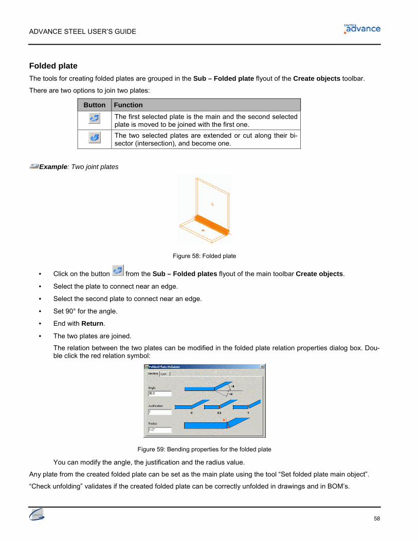
ADVANCE STEEL USER’S GUIDE
58
Folded plateThe tools for creating folded plates are grouped in the Sub – Folded plate flyout of the Create objects toolbar.
There are two options to join two plates:
Button FunctionThe first selected plate is the main and the second selectedplate is moved to be joined with the first one.The two selected plates are extended or cut along their bi-sector (intersection), and become one.
Example: Two joint plates
Figure 58: Folded plate
• Click on the button from the Sub – Folded plates flyout of the main toolbar Create objects.
• Select the plate to connect near an edge.
• Select the second plate to connect near an edge.
• Set 90° for the angle.
• End with Return.
• The two plates are joined.
The relation between the two plates can be modified in the folded plate relation properties dialog box. Dou-ble click the red relation symbol:
Figure 59: Bending properties for the folded plate
You can modify the angle, the justification and the radius value.
Any plate from the created folded plate can be set as the main plate using the tool “Set folded plate main object”.
“Check unfolding” validates if the created folded plate can be correctly unfolded in drawings and in BOM’s.

ADVANCE STEEL USER’S GUIDE
59
Coordinate systems
In AutoCAD / Advance the World Coordinate System (WCS) is fixed and the User Coordinate Systems (UCS) canbe moved/rotated. The UCS takes precedence in almost all cases except where a tool specifically refers to theWCS (e.g. Define model view with 1 point in WCS).
The Advance UCS tools are placed in the Advance Standard-toolbar:
…
Figure 60: Advance UCS-tools
With the first button you open the flyout Sub – UCS with tools for object coordinate systems, coordinate system oncurved beams, coordinate systems on bisecting line and coordinate system definition.
Figure 61: Flyout Sub – UCS
You can rotate the current UCS by 90° around the X-/Y-/Z-axes of the current user coordinate system using thethree buttons:
Button FunctionUCS rotate around X
UCS rotate around Y
UCS rotate around Z
Button FunctionA current UCS can be moved to a new ori-gin point, in which the orientation of theaxes remains the same.
With “View on ucs“ and “Clipped view on ucs“ , you can set a view in the Z-axis of the UCS and clipping toimprove the view area for the required construction.
With the toolbar (flyout) Sub – Isometric view, you can choose an isometric view on the Advance model similar tothe AutoCAD – isometric views, but with a slightly different view angle.
Figure 62: Flyout Sub – Isometric view

ADVANCE STEEL USER’S GUIDE
60
Object Coordinate SystemsAdvance objects are always created relative to the current coordinate system.
Each Advance object has its own object coordinate system. The X/Y plane of the object coordinate system isperpendicular to the web (parallel to the flange) of a beam or to a plate surface. The Z coordinate points to the TOPof a beam or represents the default direction for a plate thickness.
If processing’s or connection objects are to be created at beams or plates, it is recommended to set a UCS orienta-tion corresponding to a suitable object coordinate system. For example, an object coordinate system can be acti-vated in a plate plane if a contour processing should be created in this plane.
• Rectangular plates have ten object coordinate systems.
Figure 63: Plate with 10 object coordinate systems, current object coordinate system
• Beams have six basic object coordinate systems:
Figure 64: Beam with six object coordinate systems
Choose an object coordinate system as a user coordinate system using the first tool of the flyout Sub – UCS (“UCSat object”).

ADVANCE STEEL USER’S GUIDE
61
Example: Activate an object coordinate system of a polygon plate as a UCS
Figure 65: Object coordinate system as UCS
• Click the button in the flyout Sub – UCS of the toolbar Standard.
• Select the polygon plate. The coordinate systems are displayed. The respective axis directions are dis-played as lines with different lengths. The positive Z-axis is displayed as the longest line.
• Choose one of these lines (for example the yellow line pointing upwards). A UCS is set, corresponding tothe selected coordinate system.
Coordinate systems at curved beamsA particular coordinate system tool is available for curved beams. Place an object coordinate system on any point ofa curved beam (Z axis follows the radial line) using the tool “UCS at curved beam”.
Example: Creation of a coordinate system at a curved beam
Figure 66: UCS at the curved beam (UCS has been subsequently rotated about X)
• Choose the button in the flyout Sub–UCS of the Standard toolbar.
• Select the required point on the curved beam.
• Select additional creation point for the position of the coordinate system or Return.
• The coordinate system is created.
The additional point need not even lie on the beam. Thus, a UCS can be set on a curved beam at exactly the loca-tion of an approaching beam for constructing a connection at this location.

ADVANCE STEEL USER’S GUIDE
62
UCS at bisecting lineWith the tool “UCS to bisecting line” a user coordinate system is created at the bisecting line. This tool is suitable,for example in facade construction, to create sections at the bisecting angle of two other beams.
Example: Create UCS at the bisecting angle
• Click the button in the flyout Sub – UCS of the Standard toolbar,
• Locate a point of origin for the UCS.
• Pick another point to define the Z direction.
• Pick a point to define first bisecting plane
• Pick a point to define second bisecting plane
• The X axis of the new UCS bisects the 2 picked planes
Define coordinate systemThe “Initial coordinate system” tool is usefull for placement on existing objects. The position and orientation of thecoordinate system corresponds to the coordinate system of the object at the time of creation. Thus, other objectswith identical position and orientation can be created.
For plates, a coordinate system is created with the same orientations as when the plate was created.
For beams, a coordinate system is created at the beginning of the beam system line. This coordinate system has anorientation that allows the creation of a new beam in the same orientation.
Example: Creation of a coordinate system on an object
Figure 67: Initial coordinate system
• Click the button from the flyout Sub – UCS in the Standard toolbar.
• Select the required object (the curved beam in this case). At the end of the beam a red coordinate systemline appears.
• Choose a red coordinate system line and with it a coordinate system.
• Confirm with Return - the coordinate system is created.

ADVANCE STEEL USER’S GUIDE
63
Beam processing
With the Advance beam processing almost any beam contour processing can be created. A beam can also beprocessed by another element like another beam.
The beam processing is located in two flyouts from the main toolbar Create objects.
Figure 68: Toolbars for beam processing
• Toolbar (flyout) Sub – Process section
• Toolbar (flyout) Sub – Section contour
Select one of the flyout icons then click the one beam end to be processed (examples: Trim, cope).
If two beams are individual, as for a miter cut, both beams must be identified after starting the tool. Follow the(AutoCAD-) command line prompts.
Processing is dependent on the UCS and is created parallel to the current coordinate system. You must thereforefirst setup a suitable coordinate system first. It is recommended (especially for contour processing curved beams) toplace a user coordinate system at the beam before processing.
With some commands, such as creating a rectangular processing, a center point or two diagonally opposite pointsto determine a contour must be entered after identifying the beam end.
To create diagonal points switch off the Ortho-mode.
Some of the named processing tools are running independent of the current coordinate system. Trim and copetools for example are relative to the identified objects.
Upon creating a beam processing a dialog-box to modify other parameters will pop up.
Processing objectsBeams or plates are processed when creating a processing object. Processing’s are displayed as a green contourin the model. These features are Advance Objects that cannot exist independently - they belong to a basic object(beam or plate).
Processing objects are created on the same layer as the associated basic object and can be deleted as separateobject.
Example: Object processing - beam trimming
Figure 69: Beam trimming, rotation of the end plane

ADVANCE STEEL USER’S GUIDE
64
To trim a beam, a processing object “shorten” is created into the same layer as the beam. By giving a positiveshorten value the beam is trimmed, by giving a negative shorten-value the beam is extended. The object processingis displayed in green.
If you delete the processing object you undo the beam trimming including the end plane rotation.
If you delete the beam, the processing object will also be deleted.
Rule-based beam processingSome of the beam processing (by adjusting one beam to another) is based on rules. See the command-names:“Cope parametric – rule (contour processing)”. This means that on modifying e.g. the section, the processing ismodified accordingly.
As for the joints, processing’s based on rules are controlled with a connection object, through which the featureproperties can be changed.
Figure 70: Connection object (dashed), processing object (rectangle)
The connection objects are represented in the model as gray objects (boxes).
Connection objects (boxes) can be shown by selecting one of the objects created by the joint and either using thetool “Display” from the beam processing toolbar (flyout) Sub – Process section or by right clicking on it and se-lecting the option Joint properties from the menu. Processing’s are displayed in the model by using the beam rep-resentation style “features” and for joints that only create processing objects, this is required to display the connec-tion object (box).
Process sectionThe flyout Sub – Process section contains the following tools:
Figure 71: Beam processing, Sub – Process section
Button FunctionShorten for straight and curved beams
Shorten at UCS for straight and curved beams
Miter cut
Cope
Cope skewed
Split beam

ADVANCE STEEL USER’S GUIDE
65
Button FunctionMerge beam
Cope, parametric – Rule
Cut at object – Rule: Beams are modified to other beamswith a diagonal cutCut variable – Rule: Beams can be cut on miter and brac-ing member can be modified to other beamsRepresentation of connection object set by rules
Example 1: Beam trimmed, beam end plane rotated by 30° (see figure above, sub chapter processing objects)
• Click the button in the flyout Sub – Section Process of the main toolbar Create objects.
• Identify a beam at a reference end.
• The Shorten beam dialog-box appears and the beam processing is represented as a green contour ac-cording to the default value.
• Select the Angle tab. Input the rotation angle for the beam end plane. The reference point is where thebeam system line intersects the cutting plane. The beam end plane is rotated.
Example 2: Split existing Advance beams
Figure 72: Split beam
• Click on the button in the flyout Sub – Process Section of the Create objects toolbar.
• Identify the required beam and confirm with Return.
• Select the separation point(s) and confirm with Return,
• Enter a value for the gap that should be kept between the single beams. Note that a Gap will shorten thesystem lines and not apply shorten features.
From the selected beam, two or more beams are created. Processing’s of the original beam are transferred onto thenewly created beam. In the case of merging beams, the two or more beams to be merged must be identified.

ADVANCE STEEL USER’S GUIDE
66
Section contourIn the flyout Sub – Section contour the following tools can be found:
Figure 73: Beam processing, Sub – Section contour
Button FunctionRectangular contour, Center: A rectangular contour is cutfrom the beam. It can be an outside (cope) or inside (hole)contour. The contour is created parallel to the UCS.Rectangular contour, 2 Points: The processing can be as-signed to a beam end to keep its position if the lengthchanges. The feature is created parallel to the UCS.Circular contour, center, parallel to UCS
Circular contour, 2 Points
Polygon contour: Any contour (polygonal, circular shape) canbe cut from the beam. For curved beams it is recommendedto first set a UCS on the object.Element contour processing: A straight or curved beam isprocessed through the geometry of another straight beam.Element contour - rule
Example: Creation of a circular processing in curved beams.
Figure 74: Circular processing in curved beams
• The required tool is dependent on the current UCS. Therefore, set a beam coordinate system with the tool
“UCS at curved beam” (Standard-toolbar); rotate if required so that the X/Y-plane lies on the web.
• Call the command circular contour, center from the flyout Sub – Section contour of the main Createobjects toolbar.
• Identify a beam at a reference end.
• Then set the center point of the contour processing, (0,0,0).
• The contour processing is created and the dialog-box Contour processing opens.
• Radius, position, contours (gap, width) and grid value can be changed.
Beam processing’s are a very powerful feature; for further details please refer to the Advance online Help.

ADVANCE STEEL USER’S GUIDE
67
Plate processing
The tools for plate processing are located in five different toolbars (flyouts).
Figure 75: Toolbars for plate processing
Processing objects are classified as either independent or dependent on the current coordinate system, corner fin-ishes, or features for polygon plates. The five different processing styles are each summarized in their own toolbars.
Polygon plates can be enlarged or shrunk with the tool “Shrink/enlarge polygon plates”. This tool is frequently usedin curtain wall construction to fit created elements by entering a positive or negative value (for creating glazing in-side a frame for example).
Plate processing’s are created in the model as green contours. They are always perpendicular to the plate plane.Features made by a diagonally passing element are trimmed in such a way that the processing edges are perpen-dicular to the plate plane.
Advance plate processing objects cannot exist independently - only as objects attached to a plate. The plate proc-essing’s can be deleted as a separate object. If the processed plate is deleted the feature is deleted as well. Proc-essing objects are on the same layer as the associated plate but the color is set independently as green for recog-nition. Combining individual processing objects can create any imaginable feature shape.
When creating a plate processing object a context sensitive dialog-box will open. The various tabs contain addi-tional processing options.
Plate processing – weld preparationThe weld preparation tool sets weld preparations on plate edges and change the plate front edges (in z-direction)with bevels or fillets.
The toolbar (flyout) Sub – Plate cuts contains weld preparation tools.
Figure 76: Plate processing - Sub – Plate cuts
There are five ways to create weld preparations:
• Cut plate at UCS
• Cut plate at another plate
• Miter plates
• Weld preparation, chamfer
• Weld preparation, fillet
To create a weld preparation you must select a side that has straight edges. The representation type “Exact withweld preparation” shows the resulting exact plate shape with bevels or fillets at the edges. Weld preparations arerepresented in green.

ADVANCE STEEL USER’S GUIDE
68
Example: Creation of a bevel weld preparation
Figure 77: Plate with weld preparation
• Click the button from the flyout Sub – Plate cuts of the main Create objects toolbar.
• Identify a plate at a reference edge.
• The weld preparation is created and the dialog-box Weld preparation – bevel opens. Bevel angle, bevelheight and bevel width can be changed here along with the bevel side (above/below).
Figure 78: Weld preparation - dialog box
Because the bevel angle value and bevel width X are related, the second value is calculated automatically whenone value is given.
For the bevel height you can choose either relative or absolute.
The weld preparation is related to the edges, so it is updated if the plate contour is changed.
Cut plate at UCSWith the commands cut plate at UCS and cut plate at another plate you can extend or cut a plate to the UCS or atanother plate and create a chamfer (for weld preparation).
Cutting a plate will change the plate contour. You can decide if a cut should be beveled or not. The bevel can be setas absolute or relative.
There are 3 main options to decide which kind of chamfer you want to apply to the plate:
Cut plate at plateWith this command you can extend or cut one plate to another and create a chamfer (for weld preparation) at themodified plate.
There are 3 main options to decide which kind of chamfer you want to apply to the plate:

ADVANCE STEEL USER’S GUIDE
69
Plate processing – independent from the UCSThe toolbar (flyout) Sub – Plate Contour contains plate-processing tools, which are executed independent of thecurrent user coordinate system.
Figure 79: Plate processing Sub – Plate Contour
There are four basic processing styles:
• One or two points to determine rectangular processing.
• One centre point or two points - centre point and radius point, will create a circular processing object.
• Any contour processing (digitised through points) can be developed as inner or outer contours.
• With the feature “Contour element” a plate can be processed by a beam or by another plate.
To create a plate processing, the plate is identified near a corner. Then the program requests a center or digitizedpoints that determine a processing contour.
To create points the Ortho-mode must first be turned off.
A dialog-box Plate contour opens, in which the form of the plate contour (length X, width Y) the position, contour(gap width), grid value and corner feature (radius, boring) can be specified.
Example: Plate contour element processing
Figure 80: Plate with casing and exact processing
• With this tool, a beam processes a plate. Select the type of processing you require with the switch in theCreate objects toolbar.
Button FunctionExact cross section
Casing cross section
• Click the button (flyout Sub – Plate Contour from the main toolbar Create objects).
• Identify the plate to be modified near a corner,
• Afterwards, identify the element to be modified. The plate processing is executed.
• The dialog-box Contour processing appears. Here, the contour (gap width), grid (increment for modifyingthe length by the grips) and corner finish (fillet, boring) can be specified.

ADVANCE STEEL USER’S GUIDE
70
Plate processing – dependent on the UCSThe plate processing’s in the toolbar (flyout) Plate contour UCS are dependent on the current coordinate system.
Figure 81: Plate processings – Flyout Sub – Plate contour UCS
The following UCS-dependent processing types are available:
• Rectangular processing determined by one or two points
• Circular processing determined by a center point or two points - center and radius point
• Any contour processing digitized by points.
Make sure that a suitable user coordinate system (UCS) is set before starting the feature tool.
The procedure when creating a UCS-dependent plate processing is identical to that of UCS-independent process-ing.
There are some plate features, in addition to being independent, can also be dependent on the current user coordi-nate system (UCS). For the processing dependent on the UCS, the definition points of the object processing areplaced in the coordinate system plane and projected along the Z-direction onto the plate plane. The result is that thelength and width of the processing in the plate plane are distorted. For an independent processing, the definitionpoints and the object processing are placed directly in the plate plane.
Example: The plate processing circular contour and circular contour ucs
Figure 82: independent (circle) and dependent processing (ellipse) on the coordinate system
The above example illustrates the effect of a UCS dependent circular processing. The circular processing lies in thecoordinate system. The circle is projected onto the plate plane and presents an oval feature. The processing edgesare always perpendicular to the plate plane.
Corner processingThe toolbar (flyout) Sub – Plate Chamfer includes commands for the corner processing and fillets of plates.
Figure 83: Plate processing Plate chamfer
Corner processing can be attached in two ways, either by defining one or two points.

ADVANCE STEEL USER’S GUIDE
71
Figure 84: Corner processing on plate
Example: Corner processing with two points
• Click the button in the flyout Sub – Plate Chamfer of the main toolbar Create objects.
• Specify the first point by picking the side of the plate at the start point of the cut.
• Repeat this process for the second edge.
• The corner processing is created between the two picked points and is represented with a green contourprocessing. The properties dialog-box Plate chamfer opens in which you can change the length X and thewidth Y of the corner processing. The edge identified first represents the X direction.
Polygon plate processingPolygon plates can be processed using commands in the toolbar (flyout) Sub – Plate corner of the Create objectstoolbar, where corners can be added or deleted.
Figure 85: Plate processing Plate corner
Button FunctionTo create an additional corner, start the tool “Create corner” and select a plateedge. The additional corner is created on the mid-point of the selected edge(where its position can then be modified using the grip point).With the tool “Remove corner” a corner is deleted so a new edge is created be-tween the adjacent corner points.
Change Advance objects
Advance object (for example beams, plates) position, geometry and attributes can always be changed using:
• AutoCAD / Advance grips
• AutoCAD tools: Moving, Rotating, Copying, Mirroring
• AutoCAD command Properties
• Advance command Properties.

ADVANCE STEEL USER’S GUIDE
72
Change by gripsGrips are displayed (AutoCAD default is blue) by clicking on an element, for example a plate or its feature, and areactivated (AutoCAD default is red) by clicking on a grip. The elements geometry or features can be changed withgrips as can their size or position by dragging the grip(s). Changes using grips are limited to the X/Y-plane of thecurrent coordinate system.
Figure 86: Grips for changing the plate processing / plate
For some manipulations the grips have no effect if modified outside the UCS-X/Y-plane.
Figure 87: Advance grips for changing the beam processing
In the above example, the grip is only moveable in the X-direction.
For some objects, it is also possible to assign grid values that are effective when using the grips.
For example, a shortening can only be moved by the given grid value (increment) by the grips in the current usercoordinate system (UCS).
Grid values are always applied globally to all types of objects, so they are not stored per object. That means, if avalue was created for a plate feature, it is also applied to other new plate features that are created. This also appliesfor the gap between features and the objects that are to be processed.
AutoCAD-Manipulating toolsFor Advance objects, the following AutoCAD-Manipulating Tools are implemented:
• Move
• Rotate
• Array
• Mirror.

ADVANCE STEEL USER’S GUIDE
73
The AutoCAD standard tools such as “Move”, ”Rotate”, etc. are available by right mouse click. For this, you firstclick a grip (in red by default), then right click your mouse.
Figure 88: AutoCAD-Manipulating Tools
The right click menu is context sensitive and only the available features/tools are displayed for the object.
When changing the object geometry using AutoCAD grips the coordinates of the moving point are projected ontothe current coordinate system.
AutoCAD command propertiesIf the AutoCAD-properties of an element such as layer, color etc. are to be changed right click on the object andpick Properties (not Advance Properties). Alternatively on the command line you can type the AutoCAD-toolDDCHPROP
Figure 89: AutoCAD properties of an identified plate
Note that changing layers is easiest by selecting the objects to modify, then selecting the appropriate layer from theAutoCAD Object Properties toolbar.
Advance command properties
Each Advance object has initial default properties. The properties can be viewed and changed in the AdvanceProperties-dialog-box.
Figure 90: Advance Properties Beam dialog-box, Section tab

ADVANCE STEEL USER’S GUIDE
74
Double clicking on an object or selecting an object with a left mouse click calls The Advance Properties-dialog-box, then choose the Advance Properties or Advance Joint Properties in the popup menu.
Figure 91: Context menu
Another way to call the properties dialog-box is to select the required element and then click on the “Properties” iconfrom the Advance Standard toolbar.
Advance Properties
Presentation type – Snaps – Grips
To keep using Advance clear and simple in the different phases of construction, Advance objects have their owndifferent presentation types, for example “standard”, “features”, and “exact”.
Since the different representation types of objects correspond normally with different constructive courses, the rep-resentation types in each case put different snaps and grips are available.
The total-construction of a model is clearest in the “standard” representation type, in which no processing objectsare shown.
When processing and connecting beams / plates, the “features” representation type is very helpful, especially as therequired grips for changing the features are available.
• The representation types can be changed for each object either in their dialog-box (for example beams, plate,
Representation type tab) or clicking the button in the Advance Standard-toolbar (see chapter belowChanging representation-type).
The representation types (and the grips available in each case) are specific to each object. The examples we willuse are beam and plate objects. Please see the Advance online Help for more details.
Example: Beam representation
An Advance beam can be displayed in four representation styles:
Figure 92: Beams in the representation types “standard”, “features”, “exact”, “symbol”

ADVANCE STEEL USER’S GUIDE
75
Beam Representation type NamePresentation 1 Standard Section edges and creation axes of the beamPresentation 2 Features Section edges and processing objectsPresentation 3 Exact Section edges and gauge lines, crosses on
end points of the creation axis and four refer-ence points in the start and end plane
Presentation 4 Symbol Creation axis and a small part of the beam inthe center
In each representation type, the beam offers different grips:
Representation type NamePresentation 1 Standard End point ceration axis, reference point in
beam centerPresentation 2 Features Grips to change the processingPresentation 3 Exact Reference and corner points of the beamPresentation 4 Symbol See standard representation type
In all representation-types, a beam can be picked at the snaps “mid point”, “center”, “node”, and “end point”. Theseare different according to the representation type.
Example: Plate
For an Advance plate, four representation types are available:
Figure 93: Plate in “standard”, “features”, “exact”, “exact with weld preparation” representation types
Plate Representation type NamePresentation 1 Standard Plate contour without processingPresentation 2 Processing Plate contour with processingPresentation 3 Exact Plate contour with processing and hole pat-
ternsPresentation 4 Exact with weld
preparationLike Presentation 3, with weld preparation

ADVANCE STEEL USER’S GUIDE
76
By changing the representation type of a plate, the following grip points are available:
Plate Representation type NamePresentation 1 Standard All corner points and midpoints of the edgesPresentation 2 Processing All corner points and midpoints of the edges,
grips for changing the processingPresentation 3 Exact All corner points and midpoints of the edgesPresentation 4 Exact with weld
preparationAll corner points and midpoints of the edges
All corner points of the plates can be picked with the object snap “End point”.
Bolt and hole patterns / Shear Studs
Bolt-/hole patterns and shear studs can be created into any required plane and are dependent on the current coor-dinate system.
Bolt patterns create connections between individual Advance objects, for example beam/plate or plate/plate. Therespective connection elements and properties are stored and managed by Advance.
The structure formed by connected elements can be displayed with a special Advance command. Adding and de-leting elements to connections is simple. The connection is interpreted during the numbering so it can automaticdistinguish between main parts and attached parts.
Bolts are created in the color cyan (by default) as individual Advance elements and can be addressed and changedwith the command Advance Properties for example.
Holes are created automatically when bolts are created. If a bolt pattern is deleted the hole pattern is also deleted.
Figure 94: Bolts, holes, shear studs, all in standard presentation
You can create a hole pattern without bolts with the following options: round holes, slotted holes, countersunk holes,blind holes, threaded holes and punch marks.
Holes are, like process features, dependent objects that are displayed in green in the model. As with features, theyare only visible when the object in which they are created, is displayed using the “features” or “exact” presentationtype. To address or change hole objects (with the Advance Properties command) or to delete them, they must bevisible.
Shear studs can be created in the model exactly the same way (cyan) as bolts, with the same options for displayingand editing. Holes are dependent on their reference object regarding their representation type.
Bolt, hole patterns and shear studs have a Behavior property tab that describes if and how the element numbersare part of the structured BOM.
Figure 95: Icons Bolts/Holes/Shear Studs, tool bolt-/hole patterns

ADVANCE STEEL USER’S GUIDE
77
All three connection types, bolt patterns, hole patterns and shear studs are created with the same commands. Clickon the corresponding button to create the objects.
Figure 96: Flyout Sub – Bolt Hole patterns
Bolt-/Hole patterns and shear studs are always created in a preset area with a certain creation point or created ongauge lines. The following toolbar buttons are available:
Button FunctionRectangular area, limited through diagonally opposite corner points
Rectangular area, unlimited, with corner creation point
Rectangular area, unlimited, with center creation point
Circular area with center creation point
Bolts on gauge line of intersecting sections
With other tools, bolt-/hole patterns can be moved or separated into single bolts/holes. With the tool “Calculate griplength”, the grip length is re-calculated.
Create bolt patterns• Set a suitable user coordinate system.
• Choose the default – “bolts” from the main toolbar Create objects
• Set the representation type if required. For example with beams use the exact representation type if a boltpattern should be created on the gauge line.
• Select the required tool (according to the creation area) from the flyout Sub – Bolt Hole Patterns of the maintoolbar Create objects.
• Choose the elements to be connected.
• Define a rectangular area through two diagonally opposite corner points (... bottom-left corner, ... top-rightcorner) or one start point or one center point.
Figure 97: Bolt pattern on gauge line, “exact” beam representation, “solid” bolt representation

ADVANCE STEEL USER’S GUIDE
78
The bolt pattern is created and the dialog-box appears.
Figure 98: Dialog-box Bolts, Definition tab
Important information that can be modified in the dialog box is as follows:
• Definition: Type, grade, diameter etc.
• Size: Number of bolts in X- and Y-directions
• Distances: Distances in X/Y-direction, edge distance (= distance bolts – plate edge or beam edge)
• Representation Type: Standard, frame, solids
• Note: Assembly type (site, site drill, shop) etc.
Create hole pattern• Set a suitable user coordinate system.
• Choose the default hole pattern in the main toolbar Create objects
• Select the required tool in the flyout Sub – Bolt hole patterns icon according to the creation area.
• Identify one end of a plate or a beam.
• Create a rectangular area using two diagonally opposite corner points (... bottom-left corner, ... top-right cor-ner) or one start point or one center point.
The hole pattern is created and the dialog-box appears. Important information fields that can be modified:
• Hole definition: Type, for example slotted holes, countersunk holes etc.
• Arrangement: Number of holes in X / Y-direction
• Distance: in X / Y-direction, edge distances.
Hole representation types are depending on their reference object.
Create shear studs• Set a suitable user coordinate system.
• Choose the default shear studs in the main toolbar Create objects
• Set the representation type if required.
• Select the required tool (according to the creation area) in the flyout Sub – Bolt hole patterns of the maintoolbar Create objects.
• Choose the element that will have the shear studs.
• Define a rectangular area with two diagonally opposite corner points (... bottom-left corner, ... top-right corner)or one start point or one center point.

ADVANCE STEEL USER’S GUIDE
79
Figure 99: Shear studs in the “solid” representation type
The shear studs are created. They are displayed in standard representation and connected to a beam / platethrough a weld point. The dialog-box appears, in which the following information can be entered:
• Definition: Norm, diameter, coating etc.
• Arrangement, distances and representation type: “standard” and “solids”.
Shift bolt-/hole patternBolts or holes on the wrong surface of an object can be shifted along their axis to the correct face.
• To shift an existing bolt pattern start the tool “Shift bolt/hole” in the flyout Sub – Bolt hole patterns of themain-toolbar Create objects,
• Identify the bolt- and/or hole pattern to be moved and confirm with Return. Then identify the element (beam orplate) by picking it at the new reference plane.
Figure 100: Shift Bolts/Holes
Split bolt-/hole patternBolt patterns consisting of several bolts, can be split into single bolts. These single bolts behave as bolt patternscreated with the ‘center‘ option.
• Split a bolt pattern (or hole pattern) into single bolts by clicking the button in the flyout Sub – Bolt holepatterns of the main-toolbar Create objects and selecting one or more bolt patterns. The bolt patterns aresplit into single bolts.
Recalculate grip length
• If the grip length of bolts should be recalculated, start the tool “Calculate grip length” in the flyout Sub –Bolt hole patterns in the main-toolbar Create objects. Identify the required bolt patterns then the element(s)to be connected.
The grip length is re-calculated.

ADVANCE STEEL USER’S GUIDE
80
Bolts on gauge linesWith this tool bolts can be created on the gauge lines of the crossing sections (must touch each other).
Figure 101: Bolts on gauge lines
• Click the button in the flyout Sub – Bolt hole pattern of the main-toolbar Create objects.
• First identify the main beam, confirm with Return and then identify the other. The bolt patterns are created onthe gauge lines of the two sections. The dialog-box opens for modifying specification for bolts and positions.
Welds
Welds can be created as weld points or weld lines. These objects contain not only the weld properties but also thelogical connection between connected structural parts.
With the Advance standard template ASTemplate.dwt, weld points are created as individual elements in the formof a pink cross whereas weld lines are represented in the model as thick polylines.
Figure 102: Weld patterns (Flyout)
Weld patterns are created with the flyout Sub – Weld patterns with the tools “Weld point” and “Weld line”.
Figure 103: Weld patterns (Flyout)
• To create a weld point with its information, click on the button in the flyout Sub – Weld patterns of themain toolbar Create objects. Identify the objects to be connected, then confirm with Return and give the cen-ter point of the weld to be created.
• To create a weld line with its information, click on the button in the flyout Sub – Weld patterns of themain toolbar Create objects. Identify the objects to be connected then confirm with Return and give the startpoint for the first weld line then one or more end points.
Figure 104: Weld points, weld line

ADVANCE STEEL USER’S GUIDE
81
Weld objects can store information separately for the upper and lower weld: Basic weld, surface shape, weld de-sign, weld thickness; weld definition: Weld Location, single length, circular (continuous); representation type:“Standard” or “Off” to hide the weld; “additional information” option to add weld text for additional information.
Connections
Advance objects can be added or deleted from the bolt or weld connection objects with additional Advance tools. Atthe same time, the grip length (and bolt length) is modified.
The check tools highlight the connected objects in red. Checking bolt or weld connection objects is important toinsure the correct parts are represented on shop drawings.
Checking tool for existing connection objects are located in two flyouts:
Figure 105: Tools connections / check connections
With the first flyout Sub – Connections Advance objects can be added or deleted from a connection (change con-nections).
The second flyout Sub – Check connections contains the tools for checking and highlighting (in red) the con-nected objects.
Change connectionsFor adding or removing objects to a bolt or weld connection (with adjusting of grip and bolt length) use the tools inthe flyout Sub – Connections of the toolbar Create objects.
Figure 106: Flyout Sub – Connections
Button FunctionConnection, add objects
Connection, disconnect objects
• Click the corresponding icon in the Sub – Connections flyout.
• Identify the connecting elements
• Select the object to be added or deleted.
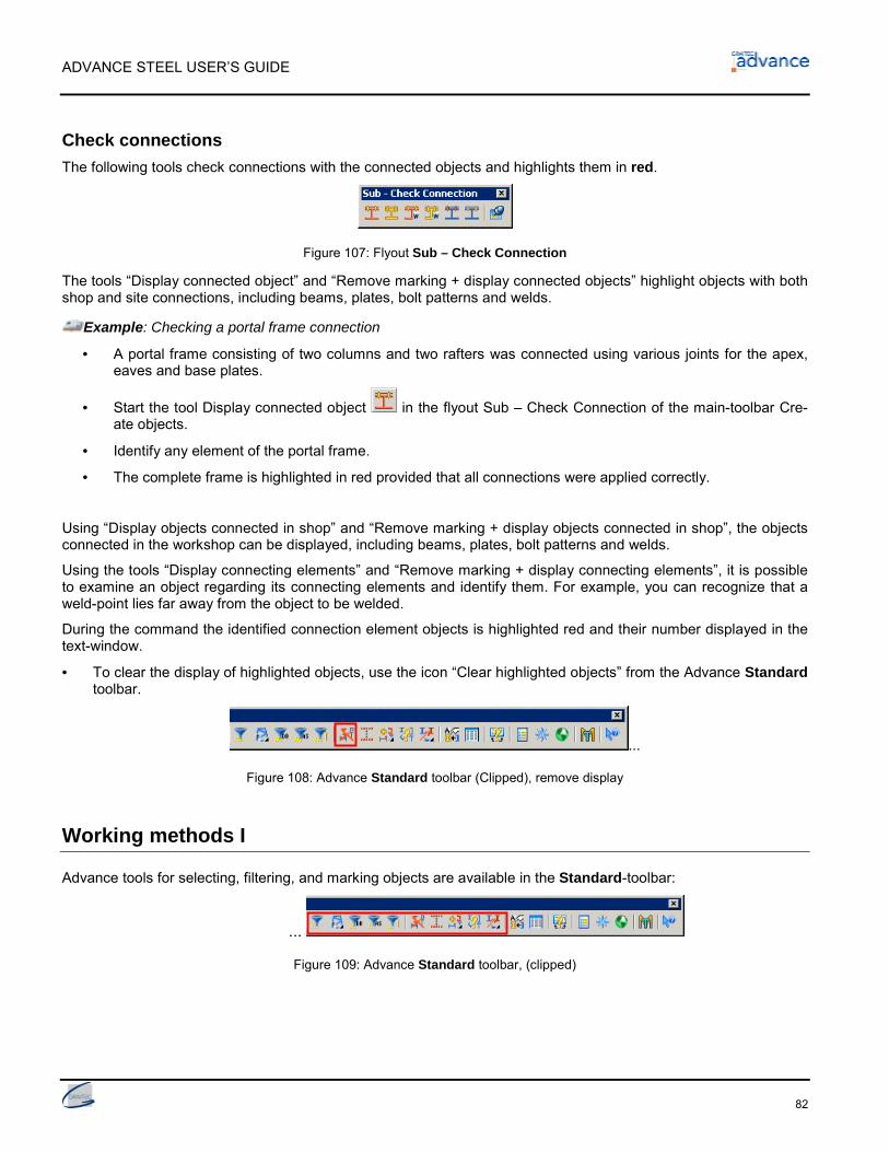
ADVANCE STEEL USER’S GUIDE
82
Check connectionsThe following tools check connections with the connected objects and highlights them in red.
Figure 107: Flyout Sub – Check Connection
The tools “Display connected object” and “Remove marking + display connected objects” highlight objects with bothshop and site connections, including beams, plates, bolt patterns and welds.
Example: Checking a portal frame connection
• A portal frame consisting of two columns and two rafters was connected using various joints for the apex,eaves and base plates.
• Start the tool Display connected object in the flyout Sub – Check Connection of the main-toolbar Cre-ate objects.
• Identify any element of the portal frame.
• The complete frame is highlighted in red provided that all connections were applied correctly.
Using “Display objects connected in shop” and “Remove marking + display objects connected in shop”, the objectsconnected in the workshop can be displayed, including beams, plates, bolt patterns and welds.
Using the tools “Display connecting elements” and “Remove marking + display connecting elements”, it is possibleto examine an object regarding its connecting elements and identify them. For example, you can recognize that aweld-point lies far away from the object to be welded.
During the command the identified connection element objects is highlighted red and their number displayed in thetext-window.
• To clear the display of highlighted objects, use the icon “Clear highlighted objects” from the Advance Standardtoolbar.
...
Figure 108: Advance Standard toolbar (Clipped), remove display
Working methods I
Advance tools for selecting, filtering, and marking objects are available in the Standard-toolbar:
...
Figure 109: Advance Standard toolbar, (clipped)

ADVANCE STEEL USER’S GUIDE
83
Choosing / selecting objectsOnly certain Advance elements can be selected for copying, numbering, exporting to a structured BOM, etc.
There are different options for selecting objects. The elements can be clicked (single selection) or selected usingAutoCAD tools like crossing windows or enclosing windows. Alternatively, previously highlighted objects (in red -see chapter above Check connections) can be selected with the tool: “Select highlighted objects”).
Another option is to select all Advance objects in an AutoCAD-drawing with the tool “Select Advance Steel objects”
.
With “Reverse selection”, the selected objects are un-selected and the un-selected objects are selected.
These selection tools also apply to hidden objects or objects on frozen Layers.
A very useful tool for selecting objects is the Advance Filter tool. This is particularly useful for: overlapping objects(for example selecting a line of a structural element that lies on the axis of a building grid), or selecting certain ob-ject types (for example plates) to put in standard representation or to beams to create a structured BOM.
Object filter
To use a command in AutoCAD / Advance you can select elements first and the tool afterwards or vice versa.
The Advance element filter is a selection before a command. The filter would cancel the command ifcalled after.
The Advance filter works in two steps:
• Click on the filter tool
• Choose object type.
For calling the Filter tool two icons are available in the Advance Standard-toolbar: “Filter selected objects”- wherethe filter tool applies only to selected objects and “Filter database” that selects through the entire AutoCAD/Advance database.
After calling the filter tool, object types must be selected from the Sub – Objects flyout.
Figure 110: Selection Objects
The following object types are available as selection objects: Structural elements, connection objects, beams,curved beams, beam – features, beam – holes, plate, plate – features, plate – holes, bolts, welds, shear studs, levelsymbols, special parts, cameras, grids.

ADVANCE STEEL USER’S GUIDE
84
Example: Filter beams from the selected Advance elements
• Select a group of Advance objects. Can be done while marking a group of objects connected with weld or
bolt objects using the tool “Display connected objects” (but may also be selected by any other means).
• Then select the highlighted objects with the tool .
• Now, start the Advance filter tool with the button (“Filter selected objects”).
• With the second icon (Sub – Objects flyout) give the object type that should be filtered and confirm withReturn.
• The selected objects are filtered and the results are displayed in the text window.
In a similar way use in Sub – Objects toolbar the icon “Filter database” to filter a certain object type from the Ad-vance database (model).
Marking / Un-marking objectsSelected objects can be highlighted individually (see above toolbar Standard) thus additional objects can be addedto the current group of highlighted objects.
Example: Selecting / marking of beams + additional marking of plates
• Select all beams in a model using the tool “Filter database” and choose beam as the selection object(flyout Sub – Objects). All beams in the model are selected (shown dotted).
• Click the “Add selected objects to marking” icon . All beams are now highlighted in red.
• Similarly repeat the above steps for plate so that all beams and plates in the model are highlighted red.
The selected objects can be deselected from the Standard toolbar using the icon “Remove selected” . Markingscan be deleted from a current group of highlighted objects.
• Filter all plates from the model and click on the button “Remove selected object from the marking” . Allselected Advance Objects (in this case - plates) are deselected.
Search / Mark objects
The tool “Search filter” from the Standard toolbar can be used to select a group of elements that have thesame properties.
On calling this tool a dialog box pops up in which search criteria, general or object specific, can be entered. Byclicking OK, the search will start. A listing of the found and highlighted objects is displayed in the text window.
The highlighted objects can be put into a selection set with the tool “Select highlighted objects” (Standard tool-bar), e.g. to copy them.
The selections will remain when other toolbars are called from the Advance Steel toolbar. It is of no importancehow the selection has been made.
Within a large model, highlighted objects (e.g. collision solids, connected objects) are not always easy to find. Theobjects can be displayed with an arrow starting from the center of the viewport for easy identification. The arrow canbe deleted or hidden, just like any other object.

ADVANCE STEEL USER’S GUIDE
85
• Click on the icon “Search highlighted objects” from the Sub – Marking flyout of the Standard toolbar. Anarrow pops up from the center of the viewport to the highlighted object.
• With the tool “Zoom to highlighted object” (Sub – Marking flyout) you can zoom directly into an area at thearrowhead by selecting the arrow.
Figure 111: Flyout Sub – Marking
Change representation typeThe representation types of the Advance elements can be changed with the Representation type tab from thedialog-boxes of the single objects.
Figure 112: Dialog-box Beam – Representation type
Other tools for representation of objects are located in the Advance Standard toolbar. These tools, in contrast tothe dialog-boxes, can change the individual representation-types faster and modify different object types (e.g.beams and plates) at the same time.
…
Figure 113: Standard toolbar - Presentation type
Button Function“Change representation type”: displays the individual representa-tion types in turn. For beams, the representation types are “stan-dard”, “features”, “exact” and “symbol” (see chapter representationtypes – snaps – grips, example beam)“Standard presentation”: directly sets the representation type to“standard” irrespective of the current presentation type.
• An additional Flyout on the toolbar has two more tools.
Button Function“Selected objects off”: hide objects from the screen representation
“Selected objects on”: hidden objects can be displayed again

ADVANCE STEEL USER’S GUIDE
86
If an object was hidden from the screen representation it can only be selected using the object filter and then dis-played again with the command “Selected objects on”.
Example: Select and display a hidden beam
• Filter the database with the tool “Filter database” from the Advance Standard-toolbar.
• Then pick Beam as the selection object in the flyout Sub – Objects of the Standard toolbar. All beams in-cluding those that are hidden are selected.
• With the tool “Representation objects on” from the Sub – Presentation flyout, all beams are displayedagain.
Views on the modelAny part-view of the model can be set with any view direction using the camera. The plane view on the model iscreated spontaneously, including zoom settings, and can be used to aid construction.
The tool Camera is located in the View toolbar.
Figure 114: View toolbar
Define the view with the camera position and a target that gives the view direction.
Alternatively, the standard AutoCAD view directions from the same toolbar may be used. It should be noted thatthese tools create views on the entire depth on the model and are not clipped to a specific plane. For more ad-vanced view creation, please see the chapter Working methods II further in this user's guide.
Structural elements
Structural elements are grouped objects that consist of basic objects such as beams and other associated featuressuch as shortenings etc. These are held together and represented by a white structural frame presented as a con-tinuous line.
Structural elements of different shapes are in the flyout Sub – Structural Elements of the Advance main-toolbarCreate objects.
Figure 115: Advance Sub – Structural Elements toolbar
• Symmetrical Flat frames and Portal frames
• Single-span bracings
• Purlins
• Pylons
• Joist
The basic objects, from which the structural elements are created, have what we call a Model Role within thestructure that determines their behavior. Basic objects with identical Model Roles are changed together, e.g. if apurlin size is changed, all purlins in the structural element will change to the same size. Exploding the structuralelement allows changes to individual members.

ADVANCE STEEL USER’S GUIDE
87
The creation dialog is specific to the type of structural element. For structural elements there is only one represen-tation type; , they differ in the type and number of the snaps and grips, with which the geometry, for example height,width etc, can be changed.
Structural elements are created in the X/Y-plane of the current user coordinate system hence the first step for cre-ating a structural-elements is to set a correct UCS.
The gray structural frame bounding box calls the properties dialog box. If beams of a structural element are to bechanged, the corresponding beam must be identified.
The tool “Select” from the Joint toolbar looks for all elements belonging to a structural frame or connection objectsto copy, rotate, or mirror individual structural elements.
Some of the structural elements use the connection object technology: joists, purlins, portal frames. The connectionobject is represented as a gray box. (3D bounding box)
Portal frame
Figure 116:Portal frame, columns centered – no cuts
A portal frame consists of two columns and two rafters. The four elements are created with a single command.From the four elements, two beams take the model role of column and two beams the model role of rafter. Ele-ments with the same model role form a group. It is not possible to directly change the properties of individual col-umns or rafters.
The portal frame is created on the current UCS plane by entering two base points and one ridge point (or angle), orsimply by right clicking to accept the default height.
To modify portal frame properties select the object’s (column or rafter) Advance Joint Properties from the contextmenu. The Layout tab in the dialog-box Portal frame has the width, height, total height and rafter angle from hori-zontal. These properties can also be changed in the Structural element dialog box.
There are two portal frame types available: frame and gable frame. The number of columns of a gable frame can bemodified in the portal frame properties dialog-box.
Flat frame
Figure 117: 2-hinged frame
This structural element is created on the current UCS plane by entering two base points and one ridge point for theheight, or by right clicking to accept the default height.
Flat frames are available in 3 types. A frame is created with a horizontal tie beam. The columns can be shifted out-wards or inwards.

ADVANCE STEEL USER’S GUIDE
88
Single-span-bracingWith this tool, diagonal members in the current X-Y-plane are created while entering a base point and a diagonalpoint.
Figure 118: Created single-span bracing
There are 3 bracing types: Created bracings, crossed bracings with or without angles in the same or opposite direc-tion, K-bracings and crossed flats. The bracings can have varying distances above and below the picked points etcby the dialog-box.
PurlinsThis creates a set of regularly spaced members on the selected rafters. Simply select the rafters and the purlins arecreated automatic. One option allows you to select a column to position an optional eaves beam.
Figure 119: Purlins
The purlins can be changed using the Purlins tab in the properties dialog box: purlin section, the projections at firstand last rafter, the extra purlin length and the span type. The distances can be modified in the Distances tab. Theintermediate distance can be changed and the number of purlins is modified to suit.
You can add an eaves beam and select the section type, position, offset and orientation.
PylonThis tool creates a structural frame that contains a pylon bracing. A pylon bracing can include a symmetrical taper.To define the structural element, first enter a base point at the first strut, a point for the width and then a third pointfor the height and inclination of the strut.
Figure 120: Pylon bracing
The fields for height and number can be set in the dialog-box.

ADVANCE STEEL USER’S GUIDE
89
JoistTo create a double angle joist, enter a start point and an end point to define the length. The third point determinesthe height and orientation of the joist.
Figure 121: Joist
Once created you can modify the length or height by using the grip points of the box or by changing the propertiesin the properties dialog box.
Half trussTo create a half truss, select a first base point where both sections converge. The second point determines thewidth and the third point is the height of the truss.
Figure 122: Half truss
Distance above and below, intermediate height and width can all be changed in the dialog-box.
Joints and connection objects
Advance contains a variety of pre-set, parametric joints to connect Advance elements. The joints consist of severalelements such as plates, stiffeners, beams, bolts and welds. An Advance joint is created with all its parts, connec-tion objects and features through a single operation. At the same time, the existing connected elements are proc-essed (shortened, coped etc) and a connection logic between the parts is established.
A joint is represented in the model by a gray box connection object that contains all the connection parts.
Joints and connection objects are grouped in the Advance main-toolbar Joints, accessible via the Advance Steel –toolbar.
Figure 123: Joints main-toolbar

ADVANCE STEEL USER’S GUIDE
90
The tools for connection objects are placed in the Sub – Joint Utilities flyout of the Advance main-toolbar Joints.
Figure 124: Sub – Joint utilities toolbar
The joints may be accessed through flyouts. The joints on the whole, are classified according to the type of the indi-vidual members:
• Beam to column connections (flyout)
• Cantilever beam to column connections (flyout)
• Beam end to end connection (flyout)
• Plate connections (flyout)
• Clip angle connections (flyout)
• Moment connections
• General bracing connection (flyout)
• HSS and flat bracing connection (flyout)
• Base plate connections (flyout)
• Tube brace connections (flyout)
• Turnbuckle bracing (flyout)
• Krupp purlin system (flyout)
• Pylon connections (flyout)
• Punch marks connections (flyout)
On the alternative UK connections toolbar the following additional flyouts can be found:
• UK Hot Rolled connections
• UK Cold Rolled connections
The connections are intelligent: If a beam connected through a connection is changed the connection automaticallyadapts to the new situation according to the set parameters.
These set parameters are stored in the connection object (the gray box), hidden by default when the connection iscreated. It contains all information of the joint but not individual component properties.
Figure 125: Connection object box
To modify a joint double click on the connection object (the gray box) that calls the properties dialog box. Connec-tion objects can be displayed, updated, entirely deleted, copied and changed. Their parameters can be transferredto other existing joints. Objects of the connection can be selected.

ADVANCE STEEL USER’S GUIDE
91
Joints A specific dialog appears when a connection is created.
After clicking on the required connection, select the members to be connected by clicking Return after each selec-tion.
Example:
... passing main beam ... Return ... beam to be connected ...Return.
Unless a special entry for existing beams exists in the connection library, the following window will appear:
Figure 126: Warning-Window for joints
The joint is created and a dialog-box with graphic explanations of the available parameters opens:
The tabs in the Joint-dialog-boxes vary according to the joint type. There are common tabs such as Poperties,Update, Table and Bolts in almost all dialog-boxes.
In the Properties tab Type pull down connections can be selected from one or more types, for example “Knee offrame with end plate and plate haunch tapered” or “straight”. The graphic representation changes according to theselected type.
Figure 127: Dialog-box Knee of frame with plate haunch - Type
A checkbox for automatic updating of a joint if individual beams are modified and a button for manual update areincluded in each joint dialog-box.
In the other tabs, for example for plates, bolts, bolt distances etc. the numbers in the sketches correspond to theinformation entry boxes.
Figure 128: Dialog-box Knee of frame with plate haunch, Endplate tab

ADVANCE STEEL USER’S GUIDE
92
The settings in the connection dialog-box can be saved to a table. Company-specific connection settings for certainbeam combinations can be saved and reused in current and future projects.
• To save a connection to the table first make the required adjustments in the dialog-box tabs.
• Then click on the Library tab and click the Save values button. Next, click on the Edit button to open the ta-ble. Enter a comment to identify the connection and fill in the appropriate section sizes.
• Click on OK to confirm and return to the connection dialog box.
Figure 129: Knee of frame with plate haunch Dialog-box Table tab
If the connected members correspond to an entry in the table the connection is created according to the entriesfrom the table (library). If there are no default values in the tables (libraries), a message is displayed as previouslydescribed above.
Beam to column jointsJoints that connect a tie beam to a column can be found in the toolbar (flyout) Sub – Beam to column of the main-toolbar Joints. Here, the tie beam ends at the column. Bolted and welded joints, with or without haunches areavailable.
Figure 130: Toolbar Sub – Beam to Column
Example: Create knee of frame with plate haunch and end plate
• Click the button from the Sub – Beam to Column flyout of the main-toolbar Joints.
• Select the column, Return and then the tie beam Return.
• The connection with haunch is created at the flange of the column and the beam to be connected is modi-fied. The tie beam is connected at the flange of a column with a plate haunch. The haunch is connected atthe tie beam by end plates. The Properties dialog-box opens.
• Under “Type”, a straight or tapered haunch can be selected. The other tabs have options to set variousgraphically represented haunch parameters.
The “Bolted knee of frame” connection has different stiffener types. Different designs are possible with or without acover plate. When designing a cover plate the column length is automatically modified.
The tool “Knee of frame bolted with haunch” creates a beam connection with haunch at the column flange. Thehaunch can be created from a beam cut or from plates. Different stiffener types are available. The haunch can bedesigned with or without a cover plate and the column is modified in length accordingly. Up to four different boltgroups can be set. Each of these bolt groups can contain several horizontal bolt lines.

ADVANCE STEEL USER’S GUIDE
93
The “Knee of frame at web, bolted”, connects a tie beam with an end plate to a column web. This connection isavailable “with one haunch” or “with two haunches”.
A knee of frame with two haunches can be created with the tool “Knee of frame, bolted with 2 haunches” from theflyout Sub – Beam to Column.
The ”Knee of frame” or the “T-connection” can be selected as welded joints.
Moment jointsThe moment connections are included in the Sub – Moment joints flyout.
Figure 131: Toolbar Sub – Moment joints
The “Moment end plate” connection is used to connect a tie beam to a column as well as two floor beams. Themoment connection creates additional support (welds, plates, stiffeners) to the connection.
The “Moment flange” joint is created out of flange plates. The connection works on all possible combination of sec-tions. Also it works for sloped and skewed situations.
Joints cantilever beam to columnGable columns/posts are connected to rafters/beams using tools from the toolbar (flyout) Sub – Cantilever beamto column found in the main-toolbar Joints. The orientation of the columns can be parallel or perpendicular to therafters. The connection is created using an end plate. Pin-ended columns are connected to fin plates welded to therafter. The connection can also be made using an end plate welded to a fin plate.
Figure 132: Toolbar Sub – Cantilever beam to column
Example: Pin-Ended Column, by Distance
Figure 133: Pin-Ended Column, by Distance
• Click the button from the flyout Sub – Cantilever beam to column in the main-toolbar Joints.
• Select the tie beam, Return, and then the column, Return.
• The pin-ended connection is created and the dialog-box pops up:
A pin-ended column is connected to a rafter by a simple fin plate (Properties tab, type: simple joint) weldedto the tie beam or through a fin plate and end plate (Properties tab, type: joint with cover plate). Informationfor plate and bolts can be modified.

ADVANCE STEEL USER’S GUIDE
94
For a joint with an end plate, the end plate is modified in width to suit the rafter and the bolts are createdautomatically on the rafter gauge lines.
The distance between the column and the rafter (perpendicular to the rafter) can be set and the length ofcolumn is changed accordingly.
The “Pin-ended column, constant length” must be modified by its system length in advance since the fin plate iscreated at the end of the column system axis.
With “Gable wall, web parallel” the joint can be layout either symmetrical or asymmetrical. For the asymmetricalconnection, a bolt group is located outside the column. The bolts in the rafter are placed automatically on the gaugelines.
With “Gable wall, web parallel” stiffeners are created into the rafter running perpendicular to the rafter or parallel tothe column.
Joints beam end to endThe joints from the toolbar (flyouts) Sub – Beam end to end joints beams for a bolted apex with or withouthaunch(es), an end plate splice and a splice joint. Changing the parameters customizes these joints.
Figure 134: Toolbar Sub - Beam end to end joints
With “Apex bolted”, two beams are spliced with bolted end plates. Up to four different bolt groups can be set.
With “Apex bolted” with one or two haunches, additional information for haunches and stiffeners can be entered.
With “Front plate splice, variable” four separate bolt patterns are created and the plates are connected to the beamswith two weld points.
With “Middle gable column” two rafters can be connected to a column using two end plates. The end plates arebolted to the rafters and welded to the double cut column.
With “Front plate splice”, two beams are spliced with end plates. It is possible to attach additional bolt lines above orbeneath.
The “Front plate splice welded, flush, vertical” adds end plates flush to the beams and welds them together. Theplate thickness can be specified in the dialog. The intersection at the beam is set in the Type tab either vertical(perpendicular) or at the bisecting angle.
A “splice joint” can be created.
The “Purlin splice” connects purlins with a C-shaped profile or flat steel. Section, spice plate, side and column canbe specified in the Splice plate tab.
Clip angle jointsThe tools in the toolbar (flyout) Sub – Clip angle joints from the main-toolbar Joints connect floor beams to beamsas well as beam to a column by clip angles.
Figure 135: Toolbar Sub – Clip angle joints

ADVANCE STEEL USER’S GUIDE
95
Example: Create a clip angle connection
Figure 136: Clip angle connection
• Click the button from the Sub – Floor beam beam flyout of the main-toolbar Joints.
• Select the passing main beam, Return.
• Select the beam to be connected, Return.
• The joint is created and the dialog-box opens.
The “Clip angle” connects a floor beam to another beam as well as a column to a beam. The attached beam can besloped to the main one.
“Clip angle skewed” creates a similar connection with a folded clip angle. The attached beam can be sloped andskewed to the main one.
“Double side clip angle” connects a floor beam and two beams as well as a column and two beams. The attachedbeams can be sloped to the main one, as the clip angle is aligned at the main beam. The connection works also fora curved passing beam or when the beams are compound or welded.
With “Double-sided web joint, angle-end plate”, opposite beams are connected to a main beam. The first beam isconnected to a double angle and the second one to an end plate.
The “Seated beam shear connection” uses welded or bolted angles to join two beams. The quantity and size ofangles are variable.
The “Joist seat bottom” joint can be created on beams or columns of all possible shapes.
Plate jointsThe tools in the toolbar (flyout) Sub – Plate joints from the main-toolbar Joints connect beams to beams. Endplate and moment end plate connections are also included.
Figure 137: Toolbar Sub – Plate joints
Example: Create double side end plate with safety bolts
Figure 138: Double-sided end plate connection
ADVANCE STEEL USER’S GUIDE
96
• Click the button in the flyout Sub – Floor beam beam of the main-toolbar Joints.
• Select the passing main beam, Return, then the first beam to be connected, Return then the second beamto be connected.
Two opposite beams are connected through a main beam by their end plates. If the connection is usedbetween floor beams then an automatic cope is created by default.
If the connection is used between a column (web) and two beams and the beams do not fit in the spacebetween the column flanges, then a trim is created on the left and right side of the flange (secondary beam).
The cope parameters can be set in four tabs of the joint properties dialog. The plate size is calculatedacording to the bolts vertical and horizontal distances. The cope length at the top and bottom and the copedepth can be set for both connected beams. The thickness of the weld line can be set separately for eachbeam.
The “Single side end plate” connects two floor beams or a column to a beam. The secondary beam can be sloped,skewed or rotated.
The “Moment end plate connection”, projections can be set at the top or bottom of the joint. Creation of a momentend plate connection is used to connect a tie beam to a column. The projections can be specified at the top or bot-tom in joints that support this feature.
The “Double side end plate with safety bolts” connects two beams to a floor beam or to a column. The attachedbeams can be sloped to the main one and a safety bolt can be added.
The “Platform splices” (toe plates) are shear connections at a beam with end plates and stiffeners. In the extendedversion up to four bolt groups can be set.
The “End plates, asymmetric” connects beams that do not run into the center of the main member (a column or abeam).
The Shear plate” connects two floor beams or one column and a floor beam.
The “Through plate” joint is similar to a shear plate, but connects two secondary beams to a column by a plate. Theplate goes through the column (main beam) and creates automatically a contour in the main beam. It works for hori-zontal or sloped/skewed beams.
The “End plate” connection welds the end plate to the tie beam and bolts it to the column or floor beam. The endplate can be created central or flush relative to the upper edge of the tie beam.
General bracing jointsThe toolbar (flyout) Sub – General bracing joints from the main-toolbar Joints, groups tools for connecting brac-ing members using gusset plates.
Figure 139: Sub – General bracing joints toolbar
The gusset plate connection can be used on a column with a base plate or on other types of beams. The requiredbolts and welds are created automatically.

ADVANCE STEEL USER’S GUIDE
97
Example: Gusset plate at column and base plate
Figure 140: 3 Gusset plate types
• Click the button in the flyout Sub – General bracing joints from the main-toolbar Joints.
• Select the column to connect, Return,
• Select the base plate to connect, Return,
• Select the diagonal to connect, Return.
• The gusset plate is created and the dialog-box opens.
“Gusset plate to column and base plate” connects a column and a base plate to a diagonal. It can be used on thecolumn web or flange.
“Gusset plate, one diagonal” joins a single diagonal.
Shortening the diagonals and modifying distances from the main beams can connect two, three or four diagonals.
A “Gusset plate” in the center can also connect two diagonals. In this case one of the diagonals is continuous andthe two others are joined at the center point.
A diagonal can be connected to a beam by gusset plate and two angles. Distances, trimming of the diagonal anda variety of other specifications can be entered in the dialog-box Angle bracing.
The “Diagonal bracing” connects a column, a longitudinal beam and a diagonal brace. Slotted butt straps are boltedto the diagonal and welded to a gusset plate. The gusset plate is welded to the column and to the longitudinalbeam. The longitudinal beam is connected to the column using an end plate.
The “Angle bracing with plate” creates and connects four bracing L-profiles by a plate. The bracing profiles arebolted to the plate.
HSS and flat bracing jointsThe toolbar (flyout) Sub – HSS and Flat bracing joints from the main-toolbar Joints, groups tools for connectingbracing members.
Figure 141: Sub – HSS and Flat bracing joints toolbar
The gusset plate connection can be used on a column with a base plate or on other types of beams. The requiredbolts and welds are created automatically.

ADVANCE STEEL USER’S GUIDE
98
Example: Create a HSS bracing middle connection with sandwich plates
• Click the button in the flyout Sub – HSS and Flat bracings joints from the main-toolbar Joints.
• Select the main beam at which to connect, Return.
• Select the first diagonal, Return.
• Select the second diagonal, Return.
• The joint is created and the dialog-box opens.
Figure 142: HSS bracing middle, with sandwich plates
“HSS bracings” connect square, rectangular or round tubes to beams with an angle, a shear plate or a foldedcleat.
The “HSS bracing middle with sandwich plates” connects one main beam and two HSS diagonals.
The “HSS bracing with sandwich plates” connects one main beam and a diagonal.
A column, a base plate (or a beam) and a diagonal can be connected with “HSS bracing with sandwich plates -additional object”.
The “HSS bracing middle with sandwich plates” connects one main beam and two HSS diagonals.
The “Flat bracing” connects a main beam and a flat diagonal by use of a plate.
Stiffener jointsThe toolbar Sub – Stiffener joints contains tools to create stiffeners and binding plates. These are created eitheron the current user coordinate system or independent from it.
Figure 143: Sub – Stiffener joints toolbar
“End plates” are attached to the system end point of beams. The beam can be shortened by the plate thickness anda construction gap created (Dialog-box End plate variable, Plate tab).
The tool “Stiffeners, perpendicular” will create stiffeners perpendicular to a beam at a picked point according to theUCS. The tool “Stiffener, UCS”, will place stiffeners in the plane of the coordinate system with the stiffener thicknessin the positive Z-direction of the current UCS. The distance between the full stiffener and flange inner sides can beset in both cases.
Three tools are available to create connecting plates between two beams. With the tool “Binding plate from point”enter a start point to create the first plate and then the intermediate distance between each other plate. With “Bind-ing plate between two points” enter a start and an end point and the plates with set distances are created. With“Binding plates, end distance” select the beams and the distance to the first plate. The distances between platescan be set in the Pattern tab of the properties dialog box.

ADVANCE STEEL USER’S GUIDE
99
Example: Create binding plate between two beams with start and end point
Figure 144: Binding plate between 2 points
• Click the button in the flyout Sub – Stiffener joints of the main-toolbar Joints.
• Select the first beam, Return, then the second beam, Return.
• Now the program requests the start and end point. Enter these.
• The binding plates are created with standard values, the dialog-box Binding plate between 2 pointsopens.
• In the Plate dialog-box tab, specify the intermediate distance, number and size of the binding plates. Thedistance between the beams will determine the thickness.
• The binding plates are welded to the beams that connect them. In the Weld line tab enter the specificationof the weld.
Base plate jointsThe toolbar (flyout) Sub – Base plate joints from the Joints toolbar has base plate connection elements and sim-ple plates.
Figure 145: Flyout Sub – Base plate joints
Example: Creation of an asymmetrical base plate
Figure 146: Joints – asymmetrical base plate
• Click the button in the flyout Sub – Base plate joints from the main-toolbar Joints.
• Identify the column to which the base plate should be attached, Return.
• If no connection settings have been saved a warning appears (default values for the section cannot befound, take the standard value of the joint.). Confirm by clicking on the OK button.
A base plate with anchor bolts is created at the end of the column. The column is shortened by the platethickness and the plate is welded to it. Different options for bolts and plate preferences are available.
The dialog-box Type field has selections for base plate with corresponding bolt pattern, bolt pattern in thecenter of the beam and symmetrical bolt pattern.
Other graphically represented parameters can be modified in the Base plate, Anchor bolts and Bolt dis-tances tabs.

ADVANCE STEEL USER’S GUIDE
100
“Horizontal base plates” can be created at raking columns. In this case the base plate is either horizontal to thebase or perpendicular to the column. There are two kinds of horizontal base plates available: symmetric and asym-metric.
Corner column connections can be done with a “Corner base plate” joints. The base plate is an L shape and boltscan be created at different locations. The base plate can be created on all profile shapes (I, U, C, square hollow,rectangular hollow, round pipes) and on combined sections like star angles and double channels.
The tool “Base plate, rotated”, creates a plate at the column in accordance to the position of the current user coor-dinate system. The underside of the base plate is positioned on the UCS plane and the column trimmed to the topof the base plate (‘top’ referring to the +Z direction of the current UCS). The base plate can be rotated around itscenter point.
For “Base plate with thrust anchor and stiffeners”, a variety of parameters can be specified to determine the thrustanchor, stiffeners and welds. The graphically illustrated dialog-box tabs assist in setting the parameters.
The tool “Base plate with cross member creates” a base plate, which can be stretched at the end of a column.Cross members (of a C-shaped profile) are bolted or welded to the flange of the column.
Tube brace jointsThe toolbar (flyout) Sub – Tube brace joints from the main-toolbar Joints connects a compression pipe to a beam.The dimensions of the elements are set by parameters.
Figure 147: Sub – Tube brace joints toolbar
To create the joint first select the beam and confirm with Return, then select the compression pipe to be connected.
Example: Create compression pipe with end plate, double-sided
Figure 148: Compression pipe with end plate, double-sided
• Click the button in the flyout Sub – Tube brace joints from the main-toolbar Joints.
• Identify the beam, Return, and then the tube, Return.
• The connection is created and the dialog-box pops up.
The tool “Compression pipe with gusset plate and but strap” is available in three variants, which for quicker access,have three different icons. The variants are: Compression pipe with slotted butt strap and gusset plate, compressionpipe with slotted pipe and gusset plate, compression pipe with slipped-in butt strap and gusset plate.
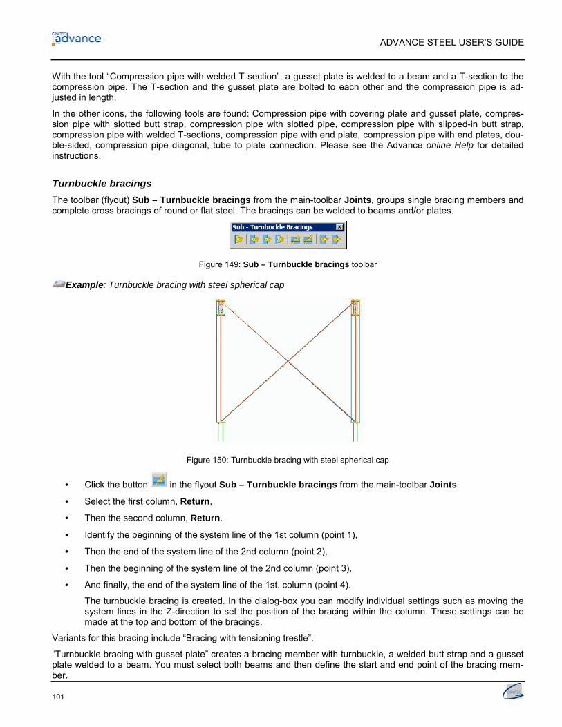
ADVANCE STEEL USER’S GUIDE
101
With the tool “Compression pipe with welded T-section”, a gusset plate is welded to a beam and a T-section to thecompression pipe. The T-section and the gusset plate are bolted to each other and the compression pipe is ad-justed in length.
In the other icons, the following tools are found: Compression pipe with covering plate and gusset plate, compres-sion pipe with slotted butt strap, compression pipe with slotted pipe, compression pipe with slipped-in butt strap,compression pipe with welded T-sections, compression pipe with end plate, compression pipe with end plates, dou-ble-sided, compression pipe diagonal, tube to plate connection. Please see the Advance online Help for detailedinstructions.
Turnbuckle bracingsThe toolbar (flyout) Sub – Turnbuckle bracings from the main-toolbar Joints, groups single bracing members andcomplete cross bracings of round or flat steel. The bracings can be welded to beams and/or plates.
Figure 149: Sub – Turnbuckle bracings toolbar
Example: Turnbuckle bracing with steel spherical cap
Figure 150: Turnbuckle bracing with steel spherical cap
• Click the button in the flyout Sub – Turnbuckle bracings from the main-toolbar Joints.
• Select the first column, Return,
• Then the second column, Return.
• Identify the beginning of the system line of the 1st column (point 1),
• Then the end of the system line of the 2nd column (point 2),
• Then the beginning of the system line of the 2nd column (point 3),
• And finally, the end of the system line of the 1st. column (point 4).
The turnbuckle bracing is created. In the dialog-box you can modify individual settings such as moving thesystem lines in the Z-direction to set the position of the bracing within the column. These settings can bemade at the top and bottom of the bracings.
Variants for this bracing include “Bracing with tensioning trestle”.
“Turnbuckle bracing with gusset plate” creates a bracing member with turnbuckle, a welded butt strap and a gussetplate welded to a beam. You must select both beams and then define the start and end point of the bracing mem-ber.

ADVANCE STEEL USER’S GUIDE
102
“Turnbuckle bracing at two beams” will create a bracing member with turnbuckle, and a welded butt strap bolted toa beam. The bracing is placed on the flange of the beams.
To create a “Turnbuckle bracing at two plates”, select the plate and set the start and end point of the bracing mem-ber. The bracing is placed on the flange of the beams.
“Turnbuckle bracing at beam – plate” combines both the above tools. The start point of the bracing is connected toa beam and the end point to a plate. The bracing is placed on the flange of the beam.
“Bracing with bar armature” will create a bracing member with a cast steel-butt strap (armature) and a butt strapbolted to the beam. Select both beams and define the start and end point of the bracing.
“Bracing with Deha-bar armature” creates a bracing member between a plate and a beam corresponding to theDeha-tension member system. You must select the beam and the plate then define the start point of the bracing atthe beam. The bracing is created between this starting point and the plate.
Krupp purlin systemFor the Z-purlins by Krupp (section class Krupp Section Purlins ZG), various joints can be created at the upperflanges of beams, using the toolbar (flyout) Sub – Krupp purlin system from the main-toolbar Joints. It includesconnections for a single-span purlin at an end-span and at a splice, and the attachment of a continuous purlin to anupper flange.
Figure 151: Sub - Krupp purlin system toolbar
To create the purlin connections, first select the beam to which the purlin is attached and confirm with Return. Thenselect one or two purlins (according to the tool used), in each case followed by Return.
Example: Creation of single-span purlins, end-span
Figure 152: Single-span purlin, End-field
• Click the button in the flyout Sub – Krupp purlin system from the main-toolbar Joints.
• Select the beam, Return
• Select the purlin, Return
• Click on the OK button in the message-window.
A cleat element is bolted or welded to the main member and the purlin will then bolted to it. In the dialog-box Krupp purlin splice you can enter more details about the connection (bolted or welded connection,construction offset, length of sleeve, information for bolts etc).

ADVANCE STEEL USER’S GUIDE
103
With the tool “Single-span purlin, splice” two single-span purlins are spliced above an upper flange.
A “Continuous purlin” can be attached to an upper flange. You can select either the connection at an end-span orthe continuous connection.
“Continuous purlin with connection element” creates a purlin splice on the upper flange. You can select between aconnection with a sleeve or with a butt strap.
Joints pylon constructionThe toolbar (flyout) Sub – Pylon joints from the main-toolbar Joints, has joints for pylon construction:
Figure 153: Sub – Pylon joints toolbar
The connection between two tubes (collinear or not) can be made by flange plates, the cross connection of twotubes with straps, and the connection of a tubular diagonal with a bracket.
To create a pylon construction connection, select the first tube (passing), and then the second (connecting) tube.
Example: Connect two tube ends with flanged connection
Figure 154: Tube ends with flanged connection
• Click the button in the flyout Sub – Pylon joints from the main-toolbar Joints.
• Select the first pipe, confirm with Return,
• Then select the second pipe and confirm with Return.
• In the message-window, click on OK.
The pipe connection is created and the dialog-box Pipe pylon splice with flange plates appears.
In the dialog-box, information for bolts, flange plates, stiffeners, ring plate 1 and ring plate 2 can be entered.
“Unparallel tube joint” is self-explanatory.
“Joint with straps” connects two tubes using an end plate with straps and optional stiffeners.
“Joint for base point” connects tubes using a cover plate, butt strap and gusset plate. The incoming tube must besquare to the first.

ADVANCE STEEL USER’S GUIDE
104
User connectionsThe tools in the Sub - User template connections toolbar create, store and re-use interactive connections.
Figure 155: Sub – User template connections toolbar
“Create template connection” stores interactive connections in a library.
Example: Create a user connection
• Create all joint elements: plates, welds, bolts (including bolt holes), cuts, …
• Save the .dwg file containing the joint elements in the folder Connection templates.
• Click the button in the flyout Sub – User template connection from the main-toolbar Joints.
• Define the name for the new template connection: MyConnection.
• Select all joint elements, confirm with Return. A blue connection object appears around the joint location.
To recall a connection, use the tool “Import template connection”. The library dialog box has a visual preview ofeach stored connection for quick recognition.
Figure 156: User connection explorer
Chose a joint and connect the beams by selecting them in the proper order. Saved joints work only if the orientationand the angle between the beams is the same as when the Joint was stored.
Punch mark jointsThe toolbar (flyout) Sub – Punch marks from the main-toolbar Joints, has tools for creating punch marks. The jointplaces the punch marks on the main element (beam or column) according to the position of a secondary element(beam or column).
Figure 157: Sub – Punch marks toolbar

ADVANCE STEEL USER’S GUIDE
105
Example: Create punch marks
Figure 158: Punch marks
• Start the tool “Punch marks” in the flyout Sub – Punch marks from the main-toolbar Joints.
• Select the main element, confirm with Return,
• Then select the second element and confirm with Return.
• The punch marks are created and the dialog-box Punch mark joint appears.
UK JointsThe toolbar UK joints (option) contains two additional flyouts: Hot Rolled Joints and Cold Rolled Joints.
The Hot Rolled Joints flyout contains the following additional connections:
• End Plate
− Connects an incoming secondary member to a passing main member by an end plate. The members canbe any profile shape and at any angle to one another. Among other things the parameters include optionsfor copes chamfers and full control of the bolts and end plate positioning. There are also options for cre-ating slotted holes. All parts are automatic bolted or welded as required.
• Double Sided End Plate
− Same as above for connecting two secondary members at each side of a main member web. Parametersgenerally as above with additional options for different sizes and layout for the individual end plates.
• Single Beam on Post End Plate
− Connects a beam over the top of a post by an end plate (cap plate) welded to the post and bolted to thebottom flange of the beam. The plate and bolt layout is fully controllable and the overhang of the beamcan be modified.
• Double Beam on Post End Plate
− As above to connect two abutting beams over the top of a post. The gap between the beams can bemodified both in width and offset.
• Eaves Haunch
− Connects a rafter / beam to a column using an end plate with a haunch. The members can be almost anyprofile shape and at any angle to one another in one plane. Various haunch options are available fromplate and section cuts to no haunch at all. Various stiffener configurations can be added and if requiredthe column top can be trimmed or beveled with various cap plate options. All bolt layouts, end plate,haunch, stiffener sizes and positions are all fully controllable. All parts are automatic bolted or welded asrequired.

ADVANCE STEEL USER’S GUIDE
106
• Apex Haunch
− Connects two rafters at the apex by end plates with haunches. The members can be of almost any profileshape and at any angle to one another in one plane (but not parallel – use end plate splice joint for this).Various haunch options are available from plate and section cuts, or even no haunch at all. All bolt lay-outs, haunch and end plate sizes and positions are all fully controllable. Option to add correction angle forpre-setting rafters to limit deflection. All parts are automatic bolted or welded as required.
• Fin Plate
− Connects an incoming secondary member to a passing main member by a fin plate. The members can beany profile shape and at any angle to one another. The parameters include many options including copechamfers, full control for the positioning of the bolts and fin plate, slotted holes, etc. The fin plate can beplaced on either side of the incoming member web or even on either of its flanges. All parts are automaticbolted or welded as required.
• Angle Cleats
− Connects an incoming secondary member to a passing main member by angle cleats. The members canbe any profile shape and at any angle to one another (in one plane). The parameters include many op-tions including cope chamfers and full control for the positioning of the bolts and angle cleats. There arealso options for creating slotted holes. The angle cleats can be placed on either side (or both sides) of theincoming member web or even on either of its flanges (or both). The angle cleats may be bolted or weldedto either member.
• Double Sided Angle Cleats
− As above for connecting two secondary members at each side of a main member web. Parameters gen-erally as above, but with additional options for different sizes and layout for the angle cleats on each sideof the connection.
• Base Plate
− Creates a base plate and anchors at the picked end of a member. The member can be any profile shapeand at any angle (columns, beams, diagonals etc). The baseplate can be set square to the member, orhorizontal or vertical to the WCS. The parameters allow full control for the positioning and size of the boltsand base plate. All parts are automatic bolted or welded as required.
• Single Tube Brace
− Connects an incoming secondary member to a passing main member by a gusset plate or bolted anglecleat on the main member and a tee (made from plate) on the secondary member. The members can beany profile shape and at any angle to one another. There are different rules for placing the bolts square tothe brace member, square to the main member or using a curved slotted hole for brace plates. The pa-rameters allow full control for the positioning and size of the bolts and plates. The orientation of the platesmay be rotated through 90 degrees. All parts are automatic bolted or welded as required.
• Double Tube Brace
− As above, but connects two secondary members to a common gusset plate on the main member. All boltlayouts and plate details can be set individually for each brace.
• Triple Tube Brace
− As above to connect three secondary members to a common gusset plate on the main member. All boltlayouts and plate details can be set individually for each brace.
• Gusset Plate – Single Member
− Connects an incoming secondary member to a passing main member by gusset plates. The members canbe any profile shape (except tubes) and at any angle to one another (in one plane). The parameters allowfull control for the positioning and size of the bolts and plates. The gusset plates may be positioned on ei-ther or both flanges or on the web of the secondary member depending on its profile shape. The gussetplates may be bolted or welded to either member.

ADVANCE STEEL USER’S GUIDE
107
• Gusset Plate – Double Member
− As above to connect two secondary members to common gusset plates on the main member.
• Gusset Plate – Triple Member
− As above to connect three secondary members to common gusset plates on the main member.
• Direct Bolting – End
− Connects an incoming secondary member to a passing main member by direct bolting. The members canbe any profile shape (except tubes) and at any angle to one another (in one plane). The parameters allowfull control for the positioning of the bolts.
• Direct Bolting – Cross
− As above to connect two crossing members.
• Lap Joint – Angle
− Connects two butted angles by forming a lap and bolts. The parameters allow full control for the position-ing of the bolts and defining the lap length.
• Lap Joint – Flat
− As above to connect flats.
• Stiffeners – Perpendicular
− Creates stiffeners perpendicular to the selected member at a given point. The member may be almost anyshape. The parameters allow full control over the stiffener size, shape and position. Patterns of stiffenersalong the member may also be created. All stiffeners are automatic welded as required.
• Stiffeners – Inclined
− As above, but when creating the stiffeners, two points must be selected to determine the angle of the stiff-eners. The angle can subsequently be changed through the parameters if required.
• Plain Cap Plate
− Creates a plain cap plate at the picked end of a member, which may be of any profile shape. The capplate may be set by plate size or by projections and can even be circular. The cap plate can be movedalong the member and the member trimmed to suit. It is possible to rotate the cap plate to form a beveledend to the member.
• Fitting Joint
− Connects an incoming secondary member to a passing main member by welds. The members can be anyprofile shape and at any angle to one another. The incoming member is automatic ‘fitted’ to the exact pro-file of the main member or can alternatively be trimmed to its face. A gap may be created between the fit-ted faces of the two members.
• Seating Cleat
− Connects an incoming secondary member to a passing main member by a seating (supporting) cleat. Themembers can be almost any profile shape and if the secondary member is passing (and not intersecting),can be at any angle to one another. The cleat may be bolted or welded to the main member but is notconnected to the secondary member. The secondary member is not trimmed, allowing this connection tobe used in conjunction with other connections – e.g. end plate.
• Cranked Beam
− Connects two abutting members by a welded mitered joint and can optionally include a center plate. Themembers may be any profile shape and at any angle to one another. The center plate can be set by platesize or by projections. If no center plate is required, set the thickness to zero.

ADVANCE STEEL USER’S GUIDE
108
• End Plate Splice
− Connects two abutting members by end plates. The members may be any profile shape, but must be par-allel to one another (for members at an angle, use the apex haunch connection). The parameters allow fullcontrol over the size and position of the bolts, plates and welds.
• Splice Plates
− Connects two abutting members by splice plates. The members may be almost any profile shape, butmust be parallel to one another. If the members are of different sizes (but approximately the same), theconnection will automatic create packing plates as required, but these can be switched off if required. Youmay optionally omit the web plates, inner flange plates or outer flange plates by setting the thickness tozero. The splice plates can be bolted or welded to either member and there are also options for slottedholes. The parameters allow full control over the size and position of the bolts, plates and welds.
Cold Rolled Joints flyout contains the following additional connections:
• Double Purlin
− Connects two cold rolled purlins to a main member. The members can be at almost any angle to one an-other but the purlins must be parallel and must not intersect the main member. The purlins may also berotated about their longitudinal axis relative to the main member. The purlin cleat can be from plate or tee,welded to the main member, or a standard supplier’s cleat, which may be either bolted or welded to themain member. In any case, the purlins are bolted to the cleat and the bolt sizes and positions are accord-ing to the supplier’s standard details. The purlin ends are also trimmed to the correct position. The joint in-cludes options to add sleeves and/or stays and a ‘fire wall condition’ is also possible. If a non-standarddetail is set, e.g. a firewall condition, with a sleeve, on a Metsec purlin, the sleeve is shown as a 10x10 barcalled ”unavailable”, since Metsec cannot supply a firewall sleeve. For a purlin by a different supplier, thisdetail may be valid and if so, the objects are created as normal. Any ‘non-standard’ details selected for aparticular supplier will result in the creation of an “unavailable” profile. All cold rolled components createdby the joint will have the correct reference name for the particular supplier. The joint can be used for bothpurlins and side rails and for all standard section shapes for the named suppliers – Zeds, C-sections, Zetaand sigma sections etc.
• Single Purlin
− As above, but for a single purlin. By default, the purlin is not trimmed enabling the joint to be used on acontinuous (multi span) purlin. For an end condition, the purlin may be trimmed or extended to give aspecified overhang, or a standard bolt end distance. Alternatively, a purlin stub may also be created.
• Non-Continuous Purlin
− Connects a non-continuous purlin to a main member. A non-continuous purlin is set as one that intersectsthe main member within part or all of its depth. The purlin cleat can be either a plate welded to the mainmember, or an angle cleat, which can be bolted or welded to the main member. In the case of a plate, it isshaped to fit the main member either into the web or around the flange. With an angle cleat, it can beplaced either on the web face, the flange face or across the flange toes of the main member. In any case,the purlin is bolted to the cleat and the bolt sizes and positions are according to the supplier’s standarddetails. The purlin end is trimmed to the specified position and the joint also includes the option to add astay.
• Double Purlin Hip Joint
− Connects two purlins to a hip rafter by a center plate with wing plates. The purlins can be at any angle tothe rafter and the macro can also be used for hip valley connections. The center plate can be eitherwelded to the rafter or bolted by a base plate. The wing plates are welded to the center plate and bolted tothe purlins using the supplier’s standard details for bolt size and edge distances.
• Single Purlin Hip Joint
− As above, but connects a single purlin to a hip rafter. There is also an alternative detail in which a singleplate is shaped and welded directly to the rafter and bolted to the purlin.

ADVANCE STEEL USER’S GUIDE
109
• Double Eaves Beam
− Connects two cold rolled eaves beams to a main member at any angle (although the two eaves beamsmust be parallel). The eaves beam cleat can be from various combinations of plate and profiles, or a stan-dard supplier’s cleat, which in any case may be either bolted or welded to the main member. The eavesbeams are bolted to the cleat and the bolt sizes and positions are according to the supplier’s standarddetails. The eaves beam ends are also trimmed to the correct position. All cold rolled components createdby the joint will have the correct reference name for the particular supplier.
• Single Eaves Beam
− As above, but for a single eaves beam. By default, the eaves beam is not trimmed enabling the joint to beused on a continuous (multi span) eaves beam. For an end condition, the eaves beam may be trimmed orextended to give a specified overhang, or a standard bolt end distance.
• Mezzanine Floor
− Creates a layout of mezzanine floor beams in handed pairs as per the various suppliers’ standard details.Picking two diagonally opposite points sets the area of the floor. There is full control for the positioning ofthe beams and options for inset, over sail and direct fix construction. Various options are also available forthe inclusion of restraint ties of different profiles and positions.
• Double Inset Floor Beam
− Connects two cold rolled floor beams to either side of a main beam, which may be almost any hot or coldrolled profile. The connection uses a standard supplier’s cleat with the appropriate layout and bolt detailsetc. A few layout options are available within the constraints of the supplier’s standard detail.
• Single Inset Floor Beam
− As above, but connects a single cold rolled floor beam to one side of a main member. This connectionalso has an alternative rule for using a fin plate welded to the main member instead of a bolted supplier’sstandard cleat. This rule can also be used when the cold rolled floor beam is not perpendicular to the mainmember.
− IMPORTANT NOTE – For certain profiles of some suppliers, a plate is NOT a supported detail as it canonly transfer shear forces through the bolts (or friction) whereas the supplier’s standard cleat may havespecial shaping to help transfer loads. In this case it is the user’s responsibility to prove the design of theconnection.
• Double Over sail Floor Beam
− Connects two cold rolled floor beams over a main beam, which may be almost any profile. The connectionuses a standard supplier’s cleat with the appropriate layout and bolt details etc, which may be bolted orwelded to the main member. Alternatively a welded plate or tee cleat can be used.
• Single Over sail Floor Beam
− As above, but connects a single cold rolled floor beam over a main member.
The above cold rolled joints currently support sections by the following suppliers: A G Brown, Albion, Ayrshire,Banro, B W Industries, Elwell, Hi Span, Kingspan, Kingspan Metl-Con (formerly Ward), Metsec, Phoenix, Stead-mans, Structural Sections and Tegral. The joints may be enhanced to support other cold rolled sections in the fu-ture.
In addition to these generic cold rolled macros, there are also several supplier specific macros as follows:
• Ayrshire Single Swage Beam Column Joint
− Connects a 220 or 300 deep Ayrshire Swage Beam to a column using the appropriate standard supplier’sbracket. Due to the very different details for the different beam sizes, the 220 connections will trim thebeam clear of the post face while the 300 connection can allow the beam to sail over the post.

ADVANCE STEEL USER’S GUIDE
110
• Ayrshire Double Swage Beam Column Joint
− Connects two 300 deep Ayrshire Swage Beams over a column using the appropriate standard supplier’sbracket. Due to the very different details for the different beam sizes, this connection only applies to the300 deep beam. For two 220 deep beams, simply apply the single connection twice.
• Ayrshire CAM
− This tool is not actually a connection macro, but is used to automatic create CAM information for manu-facture in the form of Ayrshire’s D3 file format. The CAM file can be created for the whole model or just forselected parts. You do not have to limit your selection to Ayrshire components only, as the tool will auto-matic ignore any objects that are not by Ayrshire. The output is in the form of three files: the D3 CAM fileitself, a Warning Log and an Error Log. The Warning Log contains any non-standard details, which Ayr-shire may still be able to supply but possibly at extra cost. The Error Log contains any Ayrshire Compo-nents that are detailed incorrectly and cannot be supplied along with any components that are not cur-rently supported. Any objects listed in the Error Log are EXCLUDED from the D3 CAM file. All three filescan be viewed through the AdvanceSteel Document Manager.
• Metl-Con Side Rail Anti-Sag
− This macro creates a standard anti-sag system for Kingspan Metl-Con side rails. The user selects thesupporting columns at each side of the bay, followed by the relevant side rails. The anti-sag system iscreated automatic and various options allow the strut type to be selected along with their positions andany associated diagonal ties etc.
• Metl-Con Roof Anti-Sag
− This macro creates a standard anti-sag system for Kingspan Metl-Con purlins/eaves beams. The userselects the supporting rafters at each side of the bay, followed by the relevant purlins and (optionally) aneaves beam. The anti-sag system is created automatic and various options allow the strut type to be se-lected along with their positions etc. If an eaves beam was selected, then eaves beam restraints are cre-ated.
• Metl-Con Apex Tie
− This macro creates standard Kingspan Metl-Con apex ties between two apex purlins. The apex ties canbe positioned relative to an existing anti-sag system by selection or can be positioned in the bay relative toselected rafters. Various tie types can be created.
• Structural Sections Side Rail Anti-Sag
− This macro creates a standard anti-sag system for Structural Sections side rails. The user selects thesupporting columns at each side of the bay, followed by the relevant side rails and (optionally) an eavesbeam. The anti-sag system is created automatic and various options allow the strut type to be selectedalong with their positions and any associated diagonal ties etc. If an eaves beam was selected, the anti-sag system may be suspended from it and any associated stiffener cleats and eaves restraint cleats canbe added.
• Structural Sections Roof Anti-Sag
− This macro creates a standard anti-sag system for Structural Sections purlins/eaves beams. The user se-lects the supporting rafters at each side of the bay, followed by the relevant purlins and (optionally) aneaves beam. The anti-sag system is created automatic and various options allow the strut type to be se-lected along with their positions and any associated diagonal ties etc. If an eaves beam was selected,then eaves beam restraints are created and can be connected to the brackets created by the Side RailAnti-Sag macro or can create them directly.
• Structural Sections Apex Tie
− This macro creates standard Structural Sections apex ties between two apex purlins. The apex ties can bepositioned relative to an existing anti-sag system by selection or can be positioned in the bay relative toselected rafters. Various tie types can be created.

ADVANCE STEEL USER’S GUIDE
111
• Tegral Single Swage Beam Column Joint
− Connects a 220 or 300 deep Tegral Swage Beam to a column using the appropriate standard supplier’sbracket. Due to the very different details for the different beam sizes, the 220 connections will trim thebeam clear of the post face while the 300 connection can allow the beam to sail over the post.
• Tegral Double Swage Beam Column Joint
− Connects two 300 deep Tegral Swage Beams over a column using the appropriate standard supplier’sbracket. Due to the very different details for the different beam sizes, this connection only applies to the300 deep beams. For two 220 deep beams, simply apply the single connection twice.
• Tegral CAM
− This tool is not actually a connection macro, but is used to automatic create CAM information for manu-facture in the form of Tegral’s D3 file format. The CAM file can be created for the whole model or just forselected parts. You do not have to limit your selection to Tegral components only, as the tool will auto-matic ignore any objects that are not by Tegral. The output is in the form of three files: the D3 CAM file it-self, a Warning Log and an Error Log. The Warning Log contains any non-standard details, which Tegralmay still be able to supply but possibly at extra cost. The Error Log contains any Tegral Components thatare detailed incorrectly and cannot be supplied along with any components that are not currently sup-ported. Any objects listed in the Error Log are Excluded from the D3 CAM file. All three files can beviewed through the AdvanceSteel Document Manager.
Below the UK Hot Rolled and Cold Rolled toolbar flyouts is a button called Joint macro defaults editor. This tool isused to control the default values used by the UK joints and can be configured Per joints offering greater flexibilitythan if configured globally. This tool also allows you to create multiple default profiles for each joint for use withdifferent country or customer requirements.
StairsWith Advance Steel, various types of stairs can be created. The tools for creating stairs, railings, ladders and spe-cific joints are groupped in the Stairs & Railings toolbar.
Figure 159: Advance Stairs & Railings toolbar
Spiral stairThe tool “Spiral stair” creates the central post, the handrail, the treads, their connection and the handrail. Optionallya top cape plate can be added to the column.
Define three points and the first tread (or the last one) and the stair is created. The first two points define the centralpost height and position. The third point defines the direction of the first tread (or the last one) and its width.
There are two ways to create a spiral stair:
• from the bottom to the top: the user defines the first step; the last step position is calculated according to thefirst step position, the number or the height of the steps and the rotation angle between them.
• from the top to the bottom: the user defines the last step

ADVANCE STEEL USER’S GUIDE
112
Example: Create a spiral stair
• Set an appropriate UCS.
• Click the button from the Stairs & Railings toolbar.
• Select the first point to define the spiral center: 0,0,0.
• Select the second point to define the spiral height: 0,0,9’-2”. The stair height is on the Z axis.
• Type F if you want to create the first step (or L for the last one) and confirm with Return.
• Specify the third point to define the start direction of the step and the step width: 4’-11”,0,0.
The spiral stair is created and the dialog-box opens, in which you can enter information for column, stringer, treads,post… You can select the stair direction, the type of connection between the treads and the stringers (welds, bolts,angle welded or bolted). The preferred settings can be stored in the table.
Straight stairTwo points defining the origin and the end of the stair run creates a straight stair.
Figure 160: Straight stair
Advance creates the stringers and treads with their connections to the stringers.
The width and the offset can be controlled in the properties dialog box.
The number of treads are created according to the formula generally used to get the ergonomical height and widthof the step.
Optionally a lower and upper landing can be created.
Example: Create a straight stair
• Set an appropriate UCS.
• Click the button from the Stairs & Railings toolbar.
• Select the first point to define the origin of the stair run.
• Select the second point to define the end of the stair run.
• Type 1 to align the stair in the middle and confirm with Return.
The stair is created and the dialog-box opens, in which you can enter information for treads, landings.
You can call the dialog box to edit a stair element using the right-click menu and selecting Advance Joint Proper-ties.

ADVANCE STEEL USER’S GUIDE
113
Connection objectsIf joints need to be changed later, right click on the connection gray box and select the Advance Properties. An-other option is to double-click the object.
Alternatively, right click on only one part of the joint, perhaps a plate, and choose the option Advance Joint Prop-erties in the menu.
Tools for display, select, repeat, copy and transfer connection properties are stored in the flyout Sub – Joint Utili-ties of the main-toolbar Joints.
Figure 161: Advance Sub – Joint Utilities flyout
Button FunctionCreate by template: Copies the selected connection. At the new creation point, the proper elementsmust be selected as when creating a new connection. The connection is copied with all previoussettings to the newly selected members.Display: Turns on invisible objects created with the connection. Click on Display and identify anelement of the connection.Select: Identifies all elements in a connection by first selecting a connection object (gray box).
Repeat rule: Repeats the previously executed rule for joints. The elements are selected as for thepreviously executed connection.Transfer properties: Copies parameters such as additional stiffeners or a changed haunch length toanother existing connection of the same type. The workflow of this command is to first identify anelement from each connection to be changed (any number of joints may be picked) and then selectthe connection whose properties will be transferred. All selected joints are updated to match theproperties of the last picked connection.Update: If a connection whose automatic update has been switched off in the Update tab has beenchanged then the connection object is highlighted in red. The Update tool manually corrects the is-sue.Delete all: By selecting one or more connection objects and clicking Delete all they are completelydeleted. Objects other than connection objects selected at the same time will not be deleted.
The joints library has most standard types and is continually growing. In particular cases where there is no immedi-ate direct solution we suggest using the connection closest to the requirement, set the best parameters, delete theconnection object to ‘explode’ the connection logic and then adjust the individual components Advance propertiesand finally add or delete parts as required.
Note: When deleting the connection object the intelligence of the joint is eliminated and individual members donot update automatic on a design change.
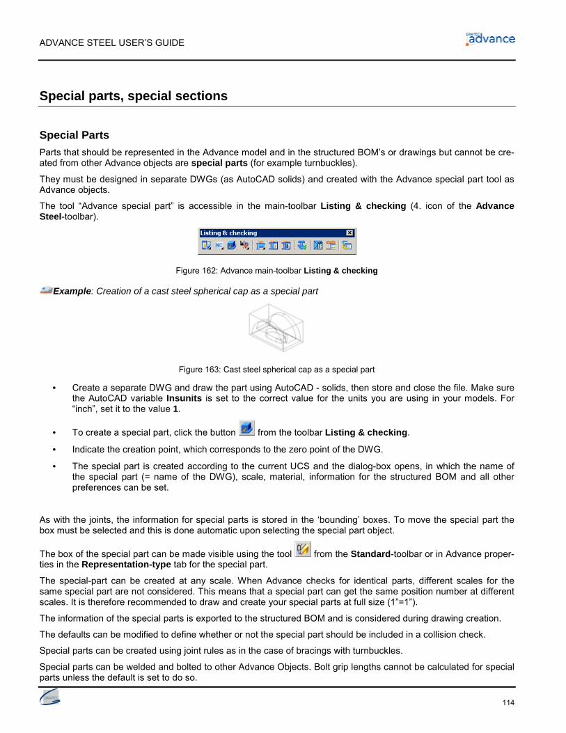
ADVANCE STEEL USER’S GUIDE
114
Special parts, special sections
Special PartsParts that should be represented in the Advance model and in the structured BOM’s or drawings but cannot be cre-ated from other Advance objects are special parts (for example turnbuckles).
They must be designed in separate DWGs (as AutoCAD solids) and created with the Advance special part tool asAdvance objects.
The tool “Advance special part” is accessible in the main-toolbar Listing & checking (4. icon of the AdvanceSteel-toolbar).
Figure 162: Advance main-toolbar Listing & checking
Example: Creation of a cast steel spherical cap as a special part
Figure 163: Cast steel spherical cap as a special part
• Create a separate DWG and draw the part using AutoCAD - solids, then store and close the file. Make surethe AutoCAD variable Insunits is set to the correct value for the units you are using in your models. For“inch”, set it to the value 1.
• To create a special part, click the button from the toolbar Listing & checking.
• Indicate the creation point, which corresponds to the zero point of the DWG.
• The special part is created according to the current UCS and the dialog-box opens, in which the name ofthe special part (= name of the DWG), scale, material, information for the structured BOM and all otherpreferences can be set.
As with the joints, the information for special parts is stored in the ‘bounding’ boxes. To move the special part thebox must be selected and this is done automatic upon selecting the special part object.
The box of the special part can be made visible using the tool from the Standard-toolbar or in Advance proper-ties in the Representation-type tab for the special part.
The special-part can be created at any scale. When Advance checks for identical parts, different scales for thesame special part are not considered. This means that a special part can get the same position number at differentscales. It is therefore recommended to draw and create your special parts at full size (1”=1”).
The information of the special parts is exported to the structured BOM and is considered during drawing creation.
The defaults can be modified to define whether or not the special part should be included in a collision check.
Special parts can be created using joint rules as in the case of bracings with turnbuckles.
Special parts can be welded and bolted to other Advance Objects. Bolt grip lengths cannot be calculated for specialparts unless the default is set to do so.

ADVANCE STEEL USER’S GUIDE
115
User SectionsNon-standard profile cross sections are called User Sections. They can be set in Advance and behave in the sameway as standard sections in the Advance-properties and Advance-functionalities.
All sections, including the User Sections, are stored in MS-Access-tables (libraries). The table structure for UserSections differs from the structure of standard sections. Standard section tables are parametric values and UserSections include only the corner points of the cross section geometry.
Accordingly User Sections are not manually entered in tables (libraries) – but are drawn and transferred by meansof the Advance User Section tool that identifies the profile cross section and enters the geometry is into the MS-Access tables (libraries).
Figure 164: User Sections
Definition of User SectionsSimilar to the special parts, a ‘User Section’ is made in two steps:
First, the section (2D cross section) is drawn with AutoCAD-elements. Then, two texts must be created with thename of the section (e.g. IPE 200) and the name of the section class (e.g. IPE).
The second step is the actual definition by a command and identification of the drawn elements. The information isproofed (for example the contours are not permitted to overlap) and created in the database. The section is nowavailable in Advance.
Exact conventions and information layers must be considered when drawing and labeling special sections. SeveralUser Section tools make this easier. These are stored in their own main-toolbar User sections with flyouts:
Figure 165: Advance main-toolbar User sections
The general workflow for drawing and defining a User Profile is as follows.
• Create a DWG and set the view direction to ‘top view’ based on the world coordinate system.
• For each User Section component you must first set a corresponding layer. This can be done with the flyoutChange current layer.
Note: The special section definition is an own application (ARX). It is automatic loaded by clicking the button
in the User section toolbar.

ADVANCE STEEL USER’S GUIDE
116
Figure 166: Flyout Change current layer
• Section outer contour: To create an exact and a simple outer contour choose the layer setting outer contouror exact outer contour. The element MUST be created using a closed polyline (pline), a circle or a rectangle.
Figure 167: User Section outer contour - in standard - and exact representation
• Section inner contour: The layer for the inner contours (simple / exact) must be activated. Closed polylines(pline), circles and rectangles are allowed as elements.
• Place a section name and assign the section to a section class. This must be done using text created onspecific layers. The layer for the respective text must be created and activated as the current layer. Only one-line Texts are permitted. They must not have blanks, and in the text for the section class, no negative sign.
Figure 168: User Section labeling and frames
• The definition frame must contain the profile with all its information and is required to create the section. Only arectangle drawn on the appropriate layer is permitted for this.
• Coordinate systems: Advance-object surfaces can be selected to place the UCS. These surfaces can also beused for User Sections. The coordinate systems at the top surface of the section are set automatic. Add coor-dinates from the Special sections toolbar the surfaces can be set by selection. A symbol is created in thecenter of the line segments.
• Corner points of the section geometry can be set as position points of the creation axis (Reference axis orSystem line). The position of the section can be moved according to these points. When creating the section,the standard position is at the center of gravity. The position points of the reference axes are set with the toolsin the reference axes menu in the user sections toolbar.
Figure 169: Flyout Add reference axis
• Select the required position from the menu, click on the screen so the cursor becomes a crosshair, then pickthe respective corners on the outer contour (using object snap!) or from another point. A symbol is createdautomatic on the corresponding layer.

ADVANCE STEEL USER’S GUIDE
117
• Creating Sections: Sections are created from the geometric information and are saved in the database. Clickone of the icons Create selected section or Create all sections (several special sections can be designed inone drawing). Select the section to create by picking the frame. A message is displayed to indicate successfulcreation of the section(s).
Figure 170: Flyout Special sections - creation
• Once the database is loaded in Advance (icon Update defaults from the main-toolbar Listing & Checking)the newly created section is available for use.
• If changes must be made to the geometry of existing User Sections, the geometry should be changed in the2D drawing and the section recreated. Advance will replace the existing entries in the database when auditingthe section names.
Please keep the drawings where you set the geometry of the sections, as there is no option (as yet) tolocate these sections if moved. All cross sections must be redrawn when databases are lost.
User Sections CreationAfter creating a User Section it is ready for use. Two options are available:
• Choose the last icon Other section in the toolbar (flyout) Sub – Section classes from the main-toolbar Createobjects and select the required special section.
Figure 171: Create special section (1)
• Click on the Beam icon in the main-toolbar Create objects and create a section of the last created type.
Figure 172: Create special section (2)
• The Beam dialog-box opens. Choose your user section from the list under Section class and Section.

ADVANCE STEEL USER’S GUIDE
118
Working methods II
Model BrowserThis tool gives complete control over all elements of a model. At any time this tool can be open to show up-to-dateinformation on each object.
The model browser is accessible from the Standard toolbar:
Model browser
Figure 173: Model browser
Elements can be sorted by main or single part mark. The element properties can be displayed in the model browserby creating or removing some additional columns:
• Right click in the table
• Select create column from the context menu. The list of properties pops up.
• Select the properties you want displayed in the model browser. The model browser displays the selected prop-erties.
Properties can be modified from inside the Model Browser. When Edit properties is checked some of the proper-ties for the selected lines of the Model Browser can be changed.
Model viewsIf you construct a large model with many elements an isometric view can get confusing.
The model view feature creates local view areas that show only those elements that lie within specific boundaries.Slices are cut from the model for better visualization, e.g. to work on a single frame in a 2D-view.
The view direction can be set and nodes can also be viewed from 6 different directions at the same time.
The toolbar (flyout) Sub – Model view is accessible by the Advance Standard-toolbar:
Figure 174: Advance Model view toolbar
First select the presentation in a single window (icon “Define model view”) or in 6 windows at the same time (icon“Define model view with 6 windows”).
To define the box and the view direction different methods are available in the course of the command (see exam-ple below).
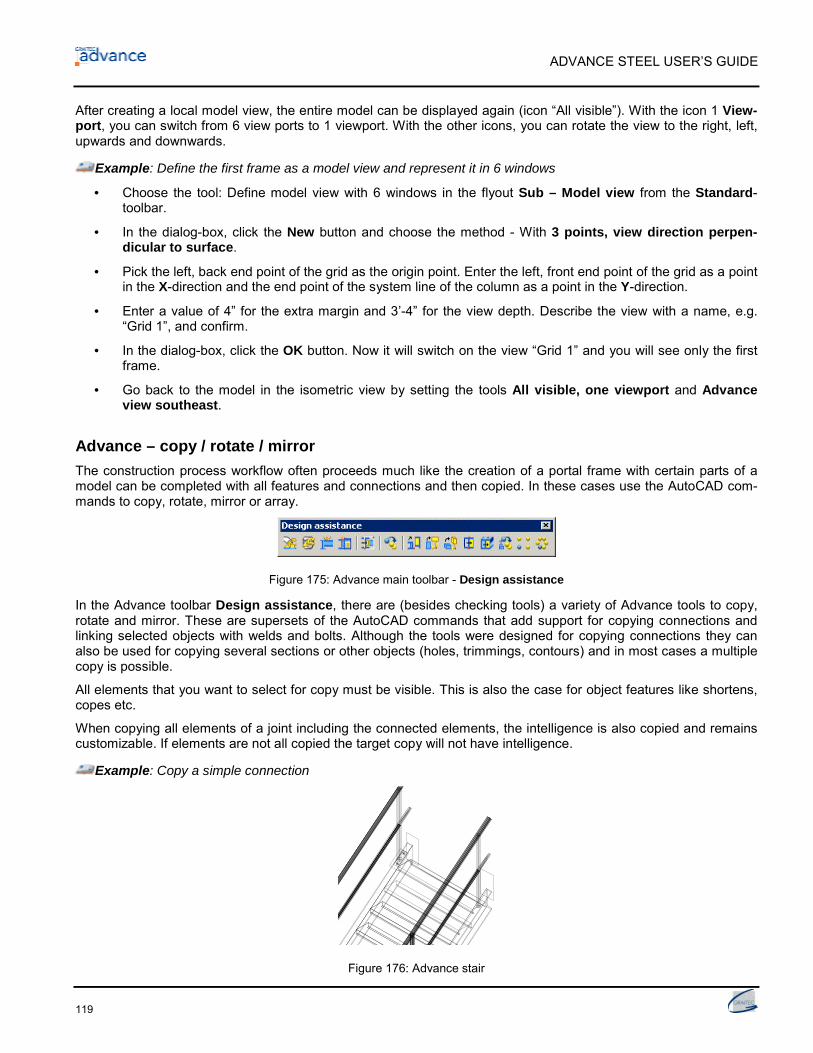
ADVANCE STEEL USER’S GUIDE
119
After creating a local model view, the entire model can be displayed again (icon “All visible”). With the icon 1 View-port, you can switch from 6 view ports to 1 viewport. With the other icons, you can rotate the view to the right, left,upwards and downwards.
Example: Define the first frame as a model view and represent it in 6 windows
• Choose the tool: Define model view with 6 windows in the flyout Sub – Model view from the Standard-toolbar.
• In the dialog-box, click the New button and choose the method - With 3 points, view direction perpen-dicular to surface.
• Pick the left, back end point of the grid as the origin point. Enter the left, front end point of the grid as a pointin the X-direction and the end point of the system line of the column as a point in the Y-direction.
• Enter a value of 4” for the extra margin and 3’-4” for the view depth. Describe the view with a name, e.g.“Grid 1”, and confirm.
• In the dialog-box, click the OK button. Now it will switch on the view “Grid 1” and you will see only the firstframe.
• Go back to the model in the isometric view by setting the tools All visible, one viewport and Advanceview southeast.
Advance – copy / rotate / mirrorThe construction process workflow often proceeds much like the creation of a portal frame with certain parts of amodel can be completed with all features and connections and then copied. In these cases use the AutoCAD com-mands to copy, rotate, mirror or array.
Figure 175: Advance main toolbar - Design assistance
In the Advance toolbar Design assistance, there are (besides checking tools) a variety of Advance tools to copy,rotate and mirror. These are supersets of the AutoCAD commands that add support for copying connections andlinking selected objects with welds and bolts. Although the tools were designed for copying connections they canalso be used for copying several sections or other objects (holes, trimmings, contours) and in most cases a multiplecopy is possible.
All elements that you want to select for copy must be visible. This is also the case for object features like shortens,copes etc.
When copying all elements of a joint including the connected elements, the intelligence is also copied and remainscustomizable. If elements are not all copied the target copy will not have intelligence.
Example: Copy a simple connection
Figure 176: Advance stair

ADVANCE STEEL USER’S GUIDE
120
• The connection to be copied is a connection between a stair stringer and a handrail post with a base plate.The stringer profile is connected to the base plate by two bolts; the handrail post is shortened and welded tothe base plate. This base detail must be copied to another handrail post. Make sure that all elements arevisible, including the processing object at the post (if required, change Presentation type tab of the corre-sponding dialog-box).
• Click the button from the Design assistance toolbar.
• If no selection has been made yet, select the elements you want to copy (base plate, two bolts, welds,trimming) and Return.
• Enter the start and end points for the copying. It is recommended to use the end of the system lines of theposts (visible in the “Standard” representation).
• Now the coordinates of the copy vectors must be entered. Click Return for all coordinates (X, Y, Z)
• At the copy destination, the objects that correspond to the objects in the initial situation are requested. Theinitial elements are highlighted with dotted lines. Select the object corresponding with the highlighted one atthe copy destination. This correctly assigns the connection objects.
• Other destination points can be entered for a multi copy. The tool is closed by clicking Enter or Esc.
With this Advance copy tool, a complete detail with all features can be copied to another location.
The following other Advance commands for copy, rotate and mirror are available in the main-toolbar Design assistance:
Button FunctionAdvanced copy
Copy
Copy and rotate, 2D
Copy and rotate, 3D
Copy and mirror, 2D
Copy and mirror, 3D
Copy with Adjustment
Copy, rectangular array
Copy, polar array

Numbering
In this chapter:■ Numbering tool■ Start The Numbering■ Numbering Options■ Create main part

ADVANCE STEEL USER’S GUIDE
122
Numbering tool
The Advance numbering tool automatic numbers Single Parts and Assemblies for the entire model. The basis fornumbering is finding identical parts that should have the same number.
The elements are compared by geometry, material properties, coating and commodity (and behavior). The proper-ties name and lot/phase are not considered for numbering. The Model Role is used by the automatic prefix tool toassign prefixes but not used directly for numbering.
At first all structural parts should be numbered so start with single part number.
The program then determines the assembly numbers for parts connected in the shop. The biggest part of an as-sembly is the main part and will get an assembly number and all other parts are considered attached and will havea single part number.
During the numbering process beams and then plates are first to be numbered. In each case the group with themost elements will get the lowest number.
If nothing is selected the entire model is numbered. When Advance objects are selected only these items are num-bered. The results in either case are recorded in the AutoCAD text window (or by a default setting be recorded in atext file instead that can be saved).
All numbering tools are stored in the first part of the Advance main-toolbar Numbering, drawing.
Figure 177: Advance main-toolbar Numbering, drawing
• The first toolbar button is a switch between Single Parts / Assemblies.
Button FunctionSwitch to Single Parts
Switch to Main Parts
• According to the switch position, the following numbering tools refer to single parts or to assemblies. Unlessboth single part and assembly numbering are done together (recommended), then single part numberingMUST be done first.
• The other icons in the flyout Sub – Numbering are tools for assigning and deleting single part and assemblynumbers and defining their prefixes.
Figure 178: Flyout Sub – Numbering
• In the flyout Sub – Display POS from the main-toolbar Numbering, drawing a variety of tools are available tocheck the numbering correctness.
• The commands to create main and assembly parts are in the flyout Sub – POS check of the main-toolbarNumbering, drawing.

ADVANCE STEEL USER’S GUIDE
123
Start the numbering
• Start the numbering process using the numbering tool from the flyout Sub – Numbering in the Advancetoolbar Numbering, drawing.
• A dialog-box pops up. The numbering for single parts and assembly parts can be done in one step or sepa-rately. Unless both single part and assembly numbering are done together (recommended), then single partnumbering must be done first.
Figure 179: Flyout Numbering dialog
Example 1: Single parts numbering
• Check the option Process single parts.
• By default single parts numbers begin with 1000 and increase by 1.
• Select one of the available methods.
• Start the numbering process by clicking OK in the window.
The assigned numbers are visible in the Structured BOM tab of the object dialog-boxes.

ADVANCE STEEL USER’S GUIDE
124
Example 2: Assembly numbering
• Check the option Process assemblies.
• By default assembly numbers begin with 1 and increase by 1.
Figure 180: Assembly numbering
• Select one of the available numbering methods. For the numbering “with drawing number” define the prefixautomatically given by the drawing number process. At drawing creation, the first part gets the prefix a001,then b001, ....
• Start the numbering process by clicking on OK. The result is displayed in the AutoCAD text window.
Note that regardless of the toggle switch setting, the “Single Part” and “Assembly” numbering can be turned on/offby the checkboxes in the numbering dialog box. This can also be used to perform the recommended simultaneous“Single Part” and “Assembly” numbering.
Numbering options
Several numbering options are available in the post number method list:
• Assembly group: The numbering automatically assigns the assembly number to the single part number of themain part.
• SP No (for main part) = Assembly No: In this case the single part number for (usually) the biggest part of theassembly is assigned the same value as the assembly number instead of having an individual single part num-ber.
With this option the single part numbering and the assembly numbering MUST be done at the same time andAdvance forces this by disabling the other check boxes.
Once a numbering has been performed, it is not possible to change this option…
…UNLESS you use the tool “Ungroup identical parts” that completely remove any numbering information.
• SP No (for standalone part) = Assembly No: In this case the single part number for the standalone parts isassigned the same value as the assembly number instead of having an individual single part number.

ADVANCE STEEL USER’S GUIDE
125
Checking the results
Example: Display the single part number/assembly number of an object:
• Select the required Advance structural part by clicking on it. Open the dialog-box.
• Choose the Structured BOM tab. The Single Part and Assembly numbers are shown together with theirprefixes.
Figure 181: Numbers and prefixes
Numbering with standard partsStandard parts are created in a template model using normal Advance Steel functionality and then assigned re-quired part numbers. During a numbering process objects are compared to detect identical parts. Any part in yourcurrent model that matches a Standard Part in your template will get the same number.
The folder
...\Graitec\AdvanceSteel\Shared\StandardPartTemplate
contains the standard part models.
The templates in this folder are listed in the Standard part template property tab page of the Numbering - equalpart detection dialog box so you can then choose which template (or templates) should be used if any.
• Create a DWG model with your standard parts
• Run the numbering inside this drawing and manually set the standard part marks (and prefixes) as required
• Save this drawing to:
...\Graitec\AdvanceSteel\Shared\StandardPartTemplate
• In another model where you want to run the numbering, open the Numbering - equal part detection dialogbox; go to the Standard part template tab where all drawings from the folder above are displayed. Click Newbutton to attach a reference model, and check the option Singlepart or Assembly to use the template for sin-gle part numbering or assembly numbering.
• It could happen that in several StandardPartTemplates the same objects are set but with different part num-bers. In this case the part number of the template with the higher priority is used. To change the sequence ofthe templates use the arrow buttons in the toolbar.

ADVANCE STEEL USER’S GUIDE
126
Delete part numbersThis tool deletes the part numbers.
• Select the structural parts whose part numbers should be deleted and use the tool in the flyout Sub –Numbering of the Numbering, drawing toolbar.
On deleting the assembly numbers only the number is deleted, not the main part identification or its prefix.
Assign / Change prefixA text prefix, separate for single part and assembly numbers, can be put in front of the part number.
• Select the required elements, use the tool in the flyout Sub – Numbering and give the required prefixwithout spaces or special characters.
The assigned prefix can be displayed and changed in the Structured BOM tab of the element dialog-boxes. Youcan also assign the prefixes through the dialog box to start with.
Prefix configurationYou can configure the automatically used prefixes for the single part and assembly numbering. The prefix is basedon the model role.
Click the button in the flyout Sub – Numbering of the Numbering, drawing toolbar.
The prefix configuration dialog appears.
Figure 182: Prefix configuration dialog
Here you can set different profiles for different jobs. The required profile should be set as current.
Figure 183: Prefix configuration – set current profile

ADVANCE STEEL USER’S GUIDE
127
Create main part
Main part assignment is either done manually or by the numbering process using Create main part of assemblythat automatic detects attached parts. Alternatively, during assembly numbering the biggest part automatic be-comes the main part.
• Click the button in the flyout Sub – MP AP of the Numbering, drawing toolbar.
• Select the part you want to make the main part. The object dialog-box pops up with the Structured BOM tab.
• Enter the assembly number and close the dialog-box or just close the dialog box and run an automatic num-bering.
Create assembly part
Connected parts (by shop weld or shop bolts) can be assigned to an assembly part.
Figure 184: Assembly part
• Click the button in the flyout Sub – MP AP of the Numbering, drawing toolbar. Select one of the con-nected parts and a dialog-box pops up.
• Enter an assembly number and close the dialog-box or just close the dialog box and run an automatic num-bering.
A blue box object (the assembly part) is created around the connected parts and this becomes the mainpart of theassembly. All other parts automatic become attached parts.
For example with stairs normally one stringer is the main part and all other parts are attached parts thus identicalstringers get different numbers (depending on the numbering method). The tool “Create assembly part” creates anassembly part box that becomes the main part title in the structured BOM. All parts within the blue box are attachedparts and are listed with single part numbers – i.e. both stringers will then have the same number.
The assembly part object can be hidden using the tool from the Standard toolbar.


Checking the model
In this chapter:■ Checking the model for errors■ Collision in the model■ Numbering validation

ADVANCE STEEL USER’S GUIDE
130
Checking the model for errors
Checks are required in various steps of the modeling process. Collision checks can help track down ‘overlappingduplicate’ members, members with no connections, problem connections and general collision situations.
After numbering it is recommended to carry out a series of error checks to correct elements with duplicate partnumbers, un-numbered elements etc. With these tools, mistakes in the structured BOM and detail drawings (andthe associated costs) can be avoided.
The Advance database should also be maintained and checked from time to time with Advance “Audit checking
(database)” and “Steel construction checking” .
The checking tools are located by default on different toolbars, namely the Advance main-toolbars Design assis-tance and Listing & checking.
Figure 185: Advance Listing & checking toolbar
The main-toolbar Listing & checking contains the toolbar (flyout) with the following checking tools:
• Collisions in the Model
• Advance AUDIT checking
• Advance AUDIT checking (database)
• Steel Construction Checking.
Other icons in the same toolbar contains the Advance commands
• Display Checking Results
• Display Checking Results Again.
Figure 186: Main-toolbar Design assistance
The Design assistance toolbar (which is not turned on and off with the other toolbars on the screen) contains fourchecking tools, but not the commands “Steel construction checking” and “Display checking results again”.
Feasibility checking is done after the numbering and the tools are located together with the numbering tools in theAdvance main-toolbar Numbering, drawing.
Figure 187: Main-toolbar Numbering, drawing: correctness checking
The commands for feasibility checking are stored in the toolbars (flyouts) Sub – Display POS and Sub – POScheck.

ADVANCE STEEL USER’S GUIDE
131
Collision in the model
This tool checks collisions in beams, plates and bolts for either the entire model or a selection set.
The program makes various checks: Bolts are checked including the creation distance at the head and nut, and ifrequired can be reversed in direction. Bolt patterns are checked against each other with verification for bolting toolspacing. Holes and exact beam cross sections (including root radii) are checked, identical overlapping elements(beams/plates copied on top of themselves) and incorrectly modified elements are recognized.
The tool compensates geometric inaccuracies with a given minimum volume of the collision solids set in the de-faults. ACIS-solids are considered in the collision and collisions with a small volume are ignored.
Figure 188: Advance Listing & checking toolbar
In the toolbar Listing & checking, the following tools are available:
Button FunctionCollision test (Flyout Sub – Checking)
Display Checking Results
Display Checking Results Again
Example: Carry out a collision check for selected elements
• Select the elements that you want to check.
• Start the tool “Clash check” .
The collisions are listed in the text window with continuous index numbers.
Collision solids will not be created directly since there can be many. The results can be displayed with the tools“Display checking results” and “Display checking results again” (see below).
Display checking results“Display checking results” displays the collision solids for a particular collision by entering its index number. Theindex number is listed in the text window by the clash check.
• Start the tool by clicking on the icon (toolbar Listing & checking). The index-number of the required ob-ject is requested in the text-window:
Please index of the object:_
• Type the index number of the required object in the AutoCAD command line. The collision solid is representedin red.

ADVANCE STEEL USER’S GUIDE
132
In complex models collision solids are hard to find.
• The command “Search highlighted objects” from the Advance Standard toolbar creates a red arrow thatshows the location of the collision solids.
• Turn off the collision solids and marking arrow with the command “Clear highlighted objects” from the Ad-vance Standard toolbar.
Display checking results againThe results list from the Advance –clash check can be recalled in the text-window.
Example: List the clash check results. Listed objects are given a continuous index number.
• Click on the icon (toolbar Listing & checking); the results appear in the text window.
Advance AUDIT checkingAdvance objects have special properties that will not be taken into consideration by the AutoCAD audit checking.The Advance audit checking is specialized for Advance objects and should be done once a day to validate coordi-nates of the objects (internal checking).
The following checking tools are grouped in the flyout Sub – Checking of the Advance Listing & checking toolbar:
Figure 189: Toolbar Listing & checking, flyout Sub – Checking
Button FunctionCollision test
Activate Advance Audit AUDIT checking
Advance AUDIT checking (database)
Mark object
Steel Construction Checking
• Click the icon in the main-toolbar Listing & checking. The following message appears in the text window:
Audit extended by Advance
• If you click the icon again, the activation is switched off. In the text window, the following message appears:
Audit by AutoCAD
ADVANCE STEEL USER’S GUIDE
133
Advance audit checking (database)This command checks the database. For example, the program can recognize and delete identical shortens of abeam. To only show the errors run audit checking without fixing them.
• Click on the icon in the main-toolbar Listing & checking. The following message appears in the text win-dow:
Audit extended by Advance
Repair detected errors? (Yes / No)
With no, you get a result list of the un-fixed errors.
Mark an incorrect object with the command _AstM4CommMarkObject, confirm and enter h (handle). Enter the han-dle number from the result list.
Steel construction checkingThe command “Steel construction checking” (main-toolbar Listing & checking) will check an object’s attribute val-ues in the database with particular emphasis on the distance between bolts within a pattern.
On clicking the icon , the following request will pop up in the command line:
Should objects with serious errors be deleted ? (Yes No)
“Advance audit checking” checks attributes of an object in the database while “Steel construction checking” checksthe values.
Defining the center of gravityThe tool “Center of gravity and total weight” from the Advance main-toolbar Listing & checking calculates thecenter of gravity of a selected group of Advance-objects.
• Click the icon from the main-toolbar Listing & checking. Identify the elements to be used for the center ofgravity calculation.
The center of gravity position in relation to the world coordinate system and the total weight of the selected struc-tural parts are displayed in the AutoCAD command line.
An AutoCAD point is created at the center of gravity automatic.
Update defaultsWhen starting Advance the current system defaults are automatic loaded. If you change the default values whileAdvance is active these changes will normally not take effect until restarting Advance.
The icon (the last icon in the toolbar Listing & checking), sets new default settings without restarting Advance.This tool imports the files again and a restart is not necessary.
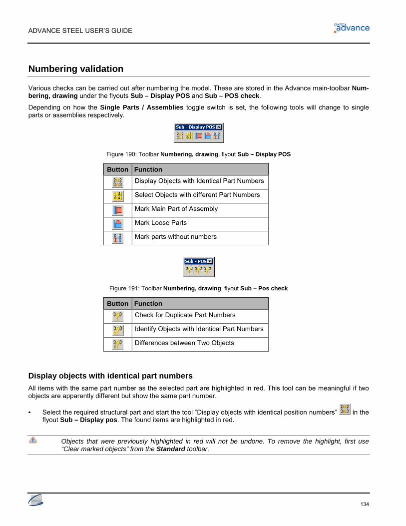
ADVANCE STEEL USER’S GUIDE
134
Numbering validation
Various checks can be carried out after numbering the model. These are stored in the Advance main-toolbar Num-bering, drawing under the flyouts Sub – Display POS and Sub – POS check.
Depending on how the Single Parts / Assemblies toggle switch is set, the following tools will change to singleparts or assemblies respectively.
Figure 190: Toolbar Numbering, drawing, flyout Sub – Display POS
Button FunctionDisplay Objects with Identical Part Numbers
Select Objects with different Part Numbers
Mark Main Part of Assembly
Mark Loose Parts
Mark parts without numbers
Figure 191: Toolbar Numbering, drawing, flyout Sub – Pos check
Button FunctionCheck for Duplicate Part Numbers
Identify Objects with Identical Part Numbers
Differences between Two Objects
Display objects with identical part numbersAll items with the same part number as the selected part are highlighted in red. This tool can be meaningful if twoobjects are apparently different but show the same part number.
• Select the required structural part and start the tool “Display objects with identical position numbers” in theflyout Sub – Display pos. The found items are highlighted in red.
Objects that were previously highlighted in red will not be undone. To remove the highlight, first use“Clear marked objects” from the Standard toolbar.

ADVANCE STEEL USER’S GUIDE
135
Select objects with different part numbersA single object of each assembly or single part number (according to the Single Parts / Assemblies switch) is se-lected and highlighted in red.
Example: Individual parts for each part number should be selected for drawing creation if done manually ratherthan by a process.
• Click on the icon in the flyout Sub – Display POS from the main-toolbar Numbering, drawing. One ele-ment for each part number in the model is selected and highlighted in red.
• If you now call the tool “Drawing – Single Part”, a shop drawing for each position number group is created.Without this command, each part would be detailed as many times as the parts exist in the model if you hadset the system default to allow duplicate drawings.
• It should be noted that this command is not required if creating drawings using a drawing ’process‘ as the pro-cess automatic filters out a single instance of each part number.
Mark main part of assemblyThe “Mark main part of assembly” command highlights the main part of an assembly in blue and all attached partsin red. A prerequisite is that the selected assembly has a main part previously identified.
• Select a part that belongs to an assembly and start the tool “Mark main part structure” in the flyout Sub –Display POS of the main-toolbar Numbering, drawing.
Main parts are presented in blue, attached parts in red, and connecting elements (bolts and welds) in green.
Mark loose partsThis tool searches the complete model for loose parts, i.e. parts that leave the workshop without any connection toother parts. Any found objects are highlighted in red.
• After calling the tool “Mark loose parts” in the Flyout Sub – Display POS of the main-toolbar Numbering,drawing, a window will pop up displaying a message about the number of single parts found.
• Clicking on the OK button will mark the loose parts.
Mark parts without numbersThis tool searches the entire model (according to the Single Parts / Assemblies setting) for structural parts that donot have a part number, e.g. because they were created after the numbering.
Note that if a part is not identified as a main part, this tool will not find any un-numbered objects if the toggle switchis set to Assemblies. Therefore newly added objects will typically only get detected if the switch is set to SingleParts.
• Start the tool “Mark parts without numbers” in the Flyout Sub – Display POS of the main-toolbar Num-bering, drawing.
Any parts found are highlighted in red.

ADVANCE STEEL USER’S GUIDE
136
Check for duplicate part numbersThis tool is found in the flyout Sub – POS check of the main-toolbar Numbering, drawing.
All parts of a group with the same part number are checked to see if they are still identical. If the parts are no longeridentical, they will need another part number. This can be the case if they were changed after the numbering.
• Click on the icon in the flyout Sub – POS check of the main-toolbar Numbering, drawing.
If any errors are found a list is displayed in the text window with the incorrect part numbers.
Identify objects with identical part numbersThe model is searched for objects of a given part number. If these objects are not identical they are highlighted indifferent colors.
• Click on the icon in the flyout Sub – POS check of the main-toolbar Numbering, drawing. The text win-dow asks for the part number in question.
• Input the part number to be checked displayed by the previous command “Check for duplicate part numbers”
. The number must include the prefix if appropriate (which is case sensitive).
The corresponding parts are highlighted in color.
Differences between two objectsTwo parts can be compared for differences.
• Click on the icon in the flyout Sub – POS check of the main-toolbar Numbering, drawing and select thetwo objects.
The program displays the differences in a window.

Lists / Bills of materials
In this chapter:■ Creating lists■ Create model extract■ Creation of structured BOM

ADVANCE STEEL USER’S GUIDE
138
Creating lists
All model objects including their graphic and non-graphic properties, features, joints and connections are stored andmanaged by Advance. Extracts are created from the numbered and saved models. The Advance List TemplateWizard creates structured BOM’s from the extracts. The created BOM’s can be saved, printed or exported in vari-ous formats.
Create model extract
The current Advance model must first be given a single part and assembly numbering and the model DWG must besaved in your selected location.
From the model information an extract is created which is exported to the BOM-module.
Start this tool by the BOM extract icon in the Sub – BOM flyout of the Advance main-toolbar Listing &checking.
A window appears where the model objects for the extract can be selected.
In the left part of the window, different saved configurations of model objects can be selected. In the right side of thewindow, different selections of the Model objects can be made for the current configuration.
Figure 192: Model objects for the structured BOM
• To save a selection set click New icon in the dialog box toolbar.
• In the appeared dialog you can select a model object to start with from the list. Input a name and click on Next.
Figure 193: Set the name for the new Model object

ADVANCE STEEL USER’S GUIDE
139
This name is displayed in the left field.
Figure 194: The new Model object
• The configuration is saved by clicking the Apply button. To continue click Next.
• In the Select destination file dialog box click OK to save the file.
Figure 195: Select destination file
If the Create list button is clicked, the information is stored and the List Template Wizard is started to createand print the information list.
The complete-model can be included in the extract or the option “Based on assembly” can be used to createstructured reports. No other entries are needed with these options (but can be if required).
Other selection options include: Lot/Phase, part number and model role. Enter the required Lot/Phase, part number(e.g. from 1-100) or the model role within the model (column, rafter etc.).
Example: Structured BOM of the columns
• After numbering and saving the model, click the icon in the Sub – BOM flyout of the Advance main-toolbar Listing & checking.
• Click the selection criteria model role and enter column in the text input field.
• Click on the Apply and Next buttons at the bottom edge of the dialog box to create the extract.
Figure 196: Selection window for structured BOM (clipped)
The option Model objects has other selection options (beam, plate, bolts, welds, shear studs, assembly part, spe-cial part).
After clicking the Apply and OK buttons, the model information is selected according to the given criteria, wherebya model-extract is created and saved within a sub-folder of the main model folder.
After each model change, it must be checked again, numbered, saved and its information re-extracted.
For each model, several model extracts for creating the structured BOM can be saved.

ADVANCE STEEL USER’S GUIDE
140
Creation of structured BOM
Start the Advance List Template Wizard by the Bom extract icon in the Sub – BOM flyout of the Advancemain-toolbar Listing & checking.
In the List – Template Wizard you can choose the formatting and the structured BOM (report) required.
Figure 197: Template wizard – list of available BOM template
An Advance template may be selected or users can define their own templates starting from an existing one.
• Select a BOM template.
• Click on the Use button.
• A dialog box appears, where you select the required model extract.
Figure 198: Model extract
• Click on OK to finish the BOM creation.
The structured BOM appears in the window. This can be printed, saved or exported to PDF (and other formats)using the corresponding icons in the menu bar.
Figure 199: Menu bars of the programs Management Tool and BOM (clipped)

ADVANCE STEEL USER’S GUIDE
141
To export the created BOM file, click on the button . Select the export format from the list.
• Save the created BOM file. A file name is requested in a new window. The BOM file is saved as a Report in thefolder
..\[model folder]\[model name]\BOM\[BOMfilename]
Figure 200: Report-window: Save the structured BOM
Figure 201: BOM with GRAITEC-formatting, example (clipped)

ADVANCE STEEL USER’S GUIDE
142
Document management – Structured BOM
The structured BOM’s linked from the model are managed in the Document Manager as NC-data and drawing de-tails.
Figure 202: Document management –structured BOM, Properties
For a structured BOM selected from the Created documents, the information for the BOM file (such as file name,state, title, path) is displayed in the Properties tab. In case the modifications in the model affect the BOM, thedrawing appears in the Update BOM branch.
Figure 203: Document Manager –structured BOM, Preview
A preview of the structured BOM is displayed in the Preview tab of the Document Manager.
• The BOM’s can also be printed directly from the Document Manager.
• Close the Document Manager by clicking the OK button.
Other details about the Document Manager can be found in the chapter Creation of projections, detail and shopdrawing, Document management and in the Advance online Help.

Creation of general arrangement and shopdrawings
In this chapter:■ Drawings■ General arrangement drawings■ Drawing management■ Document management■ Node-details■ Elevations■ Single part drawings
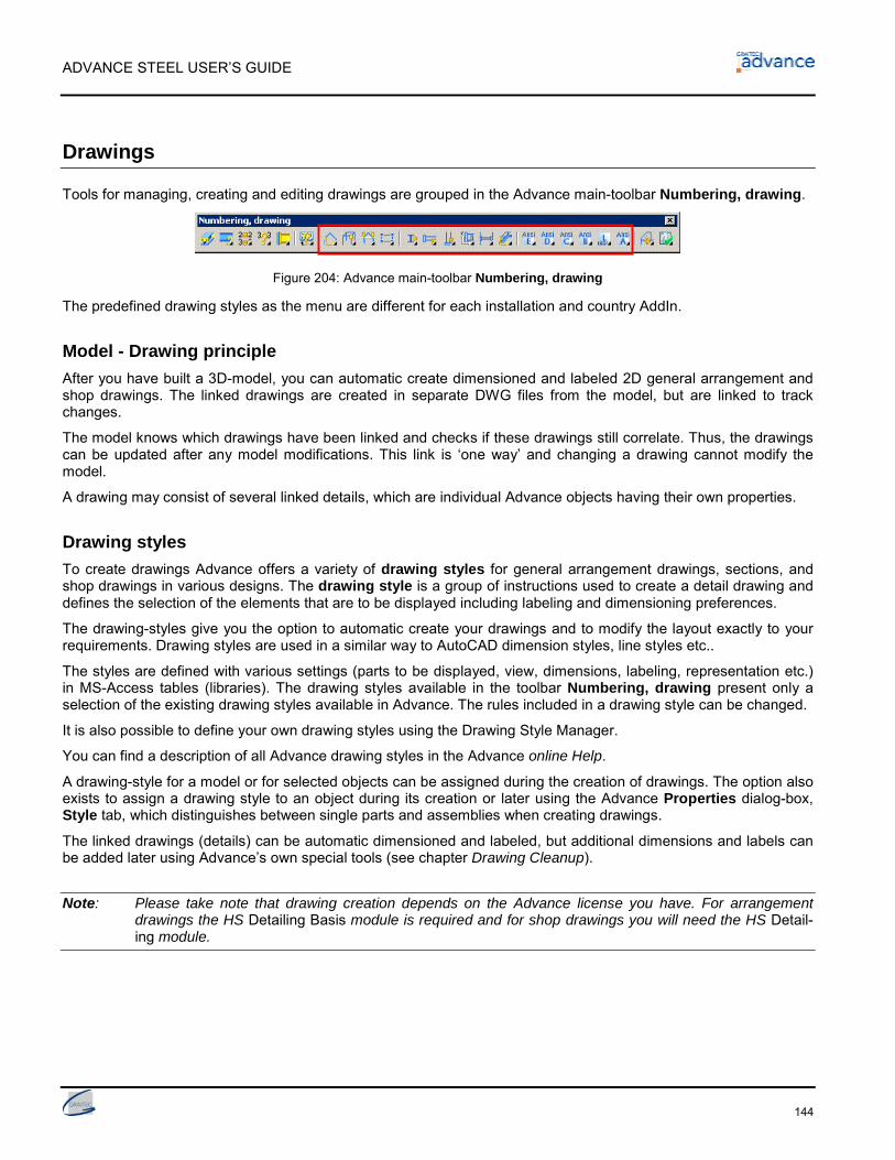
ADVANCE STEEL USER’S GUIDE
144
Drawings
Tools for managing, creating and editing drawings are grouped in the Advance main-toolbar Numbering, drawing.
Figure 204: Advance main-toolbar Numbering, drawing
The predefined drawing styles as the menu are different for each installation and country AddIn.
Model - Drawing principleAfter you have built a 3D-model, you can automatic create dimensioned and labeled 2D general arrangement andshop drawings. The linked drawings are created in separate DWG files from the model, but are linked to trackchanges.
The model knows which drawings have been linked and checks if these drawings still correlate. Thus, the drawingscan be updated after any model modifications. This link is ‘one way’ and changing a drawing cannot modify themodel.
A drawing may consist of several linked details, which are individual Advance objects having their own properties.
Drawing stylesTo create drawings Advance offers a variety of drawing styles for general arrangement drawings, sections, andshop drawings in various designs. The drawing style is a group of instructions used to create a detail drawing anddefines the selection of the elements that are to be displayed including labeling and dimensioning preferences.
The drawing-styles give you the option to automatic create your drawings and to modify the layout exactly to yourrequirements. Drawing styles are used in a similar way to AutoCAD dimension styles, line styles etc..
The styles are defined with various settings (parts to be displayed, view, dimensions, labeling, representation etc.)in MS-Access tables (libraries). The drawing styles available in the toolbar Numbering, drawing present only aselection of the existing drawing styles available in Advance. The rules included in a drawing style can be changed.
It is also possible to define your own drawing styles using the Drawing Style Manager.
You can find a description of all Advance drawing styles in the Advance online Help.
A drawing-style for a model or for selected objects can be assigned during the creation of drawings. The option alsoexists to assign a drawing style to an object during its creation or later using the Advance Properties dialog-box,Style tab, which distinguishes between single parts and assemblies when creating drawings.
The linked drawings (details) can be automatic dimensioned and labeled, but additional dimensions and labels canbe added later using Advance’s own special tools (see chapter Drawing Cleanup).
Note: Please take note that drawing creation depends on the Advance license you have. For arrangementdrawings the HS Detailing Basis module is required and for shop drawings you will need the HS Detail-ing module.

ADVANCE STEEL USER’S GUIDE
145
Drawing managementThe Document Manager is used to preview, manage and erase the linked details in separate drawings (DWGs). Ifthe model DWG or a drawing DWG is renamed the relationship is broken but can be recreated (registered). Draw-ings can also be separated (unlinked) from the model.
The Document Manager interprets which detail drawings need to be updated after modifications to the 3D-model.The updating of drawings is also controlled in the Document Manager.
ProcessesIn addition to drawing styles Advance has Processes which automatic create drawings (using appropriate drawingstyles) and arrange the linked details within a drawing (DWG) or across several drawings.
Drawing creation and AutoCAD-objectsThe drawing creation in Advance is optimized for processing Advance Objects. Standard AutoCAD-objects (e.g.lines) can also be processed. This can be done in two different ways:
• AutoCAD-elements in the 3D-Model are used to create drawings. Like Advance Objects they are automaticincluded in a corresponding drawing view but as separately created block references. The advantage is theyare completely recognized and can be modified using standard AutoCAD-commands. These blocks will not bedeleted during a detail update. When creating drawings AutoCAD-objects can be included by all Advancedrawing-commands. Pre-selecting these objects before starting the drawing tool does this. This selection isdistinct and completely independent of special commands like selecting Advance-objects. A practical exampleis the presentation of circular grid lines using AutoCAD-lines. When creating a plan view these objects can bedisplayed in the corresponding details.
• AutoCAD objects can also be created directly in linked drawings. This is done using standard AutoCAD-drawing commands in paper space. You can access the geometry of the Advance drawing objects with theENDPOINT, MIDDLE and NODE snaps as required. When Advance drawings are updated the objects createdare not deleted.
Full information on drawing creation is fully covered in the Advance online Help.
Creating drawingsBefore creating any drawings, make sure that in your model
• No collisions occur
• All parts are correctly connected
• All parts have correct part numbers.
Create drawings with the following steps:
• Select any non-Advance elements (AutoCAD lines, solids, etc.) if required, or objects with certain properties(example: Assembly). If required use the search tools in Advance to mark and select the required objects oruse the standard AutoCAD selection methods (picking, crossing window etc).
• Start the required tool (floor plan, section, single part, etc.)
• Other elements may be required - Confirm with Return.
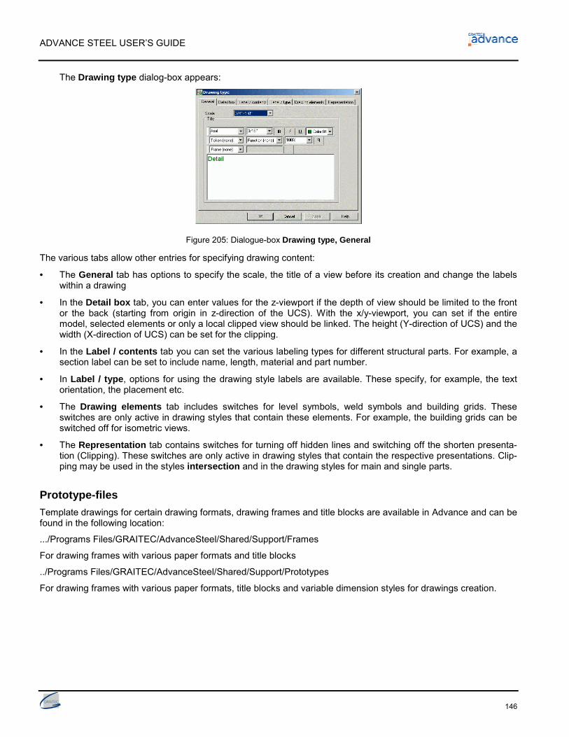
ADVANCE STEEL USER’S GUIDE
146
The Drawing type dialog-box appears:
Figure 205: Dialogue-box Drawing type, General
The various tabs allow other entries for specifying drawing content:
• The General tab has options to specify the scale, the title of a view before its creation and change the labelswithin a drawing
• In the Detail box tab, you can enter values for the z-viewport if the depth of view should be limited to the frontor the back (starting from origin in z-direction of the UCS). With the x/y-viewport, you can set if the entiremodel, selected elements or only a local clipped view should be linked. The height (Y-direction of UCS) and thewidth (X-direction of UCS) can be set for the clipping.
• In the Label / contents tab you can set the various labeling types for different structural parts. For example, asection label can be set to include name, length, material and part number.
• In Label / type, options for using the drawing style labels are available. These specify, for example, the textorientation, the placement etc.
• The Drawing elements tab includes switches for level symbols, weld symbols and building grids. Theseswitches are only active in drawing styles that contain these elements. For example, the building grids can beswitched off for isometric views.
• The Representation tab contains switches for turning off hidden lines and switching off the shorten presenta-tion (Clipping). These switches are only active in drawing styles that contain the respective presentations. Clip-ping may be used in the styles intersection and in the drawing styles for main and single parts.
Prototype-filesTemplate drawings for certain drawing formats, drawing frames and title blocks are available in Advance and can befound in the following location:
.../Programs Files/GRAITEC/AdvanceSteel/Shared/Support/Frames
For drawing frames with various paper formats and title blocks
../Programs Files/GRAITEC/AdvanceSteel/Shared/Support/Prototypes
For drawing frames with various paper formats, title blocks and variable dimension styles for drawings creation.
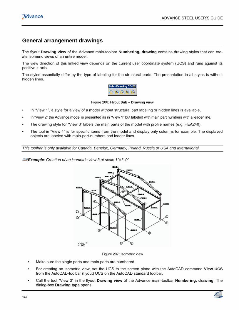
ADVANCE STEEL USER’S GUIDE
147
General arrangement drawings
The flyout Drawing view of the Advance main-toolbar Numbering, drawing contains drawing styles that can cre-ate isomeric views of an entire model.
The view direction of this linked view depends on the current user coordinate system (UCS) and runs against itspositive z-axis.
The styles essentially differ by the type of labeling for the structural parts. The presentation in all styles is withouthidden lines.
Figure 206: Flyout Sub – Drawing view
• In “View 1”, a style for a view of a model without structural part labeling or hidden lines is available.
• In “View 2” the Advance model is presented as in “View 1” but labeled with main part numbers with a leader line.
• The drawing style for “View 3” labels the main parts of the model with profile names (e.g. HEA240).
• The tool in “View 4” is for specific items from the model and display only columns for example. The displayedobjects are labeled with main-part-numbers and leader lines.
This toolbar is only available for Canada, Benelux, Germany, Poland, Russia or USA and International.
Example: Creation of an isometric view 3 at scale 1”=1’-0”
Figure 207: Isometric view
• Make sure the single parts and main parts are numbered.
• For creating an isometric view, set the UCS to the screen plane with the AutoCAD command View UCSfrom the AutoCAD-toolbar (flyout) UCS on the AutoCAD standard toolbar.
• Call the tool “View 3” in the flyout Drawing view of the Advance main-toolbar Numbering, drawing. Thedialog-box Drawing type opens.

ADVANCE STEEL USER’S GUIDE
148
• Enter the scale 1”=1’-0” in the General tab. In the Title area you can assign the title of the view (font type,style, size, color, etc.) and change the labels inside a drawing. This is entered with the scale in the lower leftcorner of the drawing (see above, view 3). Other entries for Drawing type are available in the other tabs.
Figure 208: View-detail, dialog-box Drawing type
• Click on the OK button. Another dialog box opens, in which you enter the file name and the drawing num-ber. The drawing number field is automatic filled with the next drawing number. You can select a drawingprototype file from the list.
Figure 209: Choose destination file for drawing details
• Click on the OK button. This button is not active if the drawing number or the filename is not unique.
The tool will then be started and you can select ACIS-solids.
• Confirm with Return. The view is created and saved in the named DWG file.
Drawing management
During the drawing creation you can put several details on one sheet by entering the same file name again. Movingthese views to another DWG file afterwards is possible without losing the link to the model.
Alternatively, you can specify each detail view on a new DWG at the time of creation.
• You can preview a drawing detail or list the created drawings using the Document Manager described below. To opena drawing, use the AutoCAD menu File > Open and enter the path name. The drawing can then be edited, printed etc.
If you rename or move a detail drawing, you must register (or cancel) it in the model so the relationship between thedrawing and model can be managed correctly.

ADVANCE STEEL USER’S GUIDE
149
Document management
The tools for document management are accessible by the toolbar (flyout) Sub – Drawing Management, (AdvanceStandard-toolbar and Advance toolbar Numbering, drawing). The following tools are available:
Figure 210: Toolbar Numbering, drawing, flyout Sub – Drawing Management
• Document Manager
• Register drawing in model
• Cancel drawing from model
• Drawing Style Manager
• Drawing Process Manager
• Drawing Process Suite
• Define drawing layout.
Document Manager – drawing detailsThe Document Manager lists all created drawings, bill of materials / structured BOM’s and the NC-data created fromthe model. The documents can be displayed using the Preview tab.
The Document Manager manages and presents the connection between the model and the linked drawings. Theuser can display, update, add a revision, flag the issue of drawings, add to batch plot or batch explode and deletethe drawing details in the Document Manager.
Figure 211: Document Manager – Details
The Document Manager checks automatically if drawings require an update due to model modifications or you canselect the drawings to be checked. Drawing updates are done directly from the Document Manager. It is also possi-ble to display a drawing in the Preview tab although no changes can be made to it.
• Call the Document Manager using the first icon in the Sub – Drawing management toolbar.
• If you click on Details under Project documents (in left half of the Document Manager), the created docu-ments are listed (in right half of the Document Manager window). The current drawings are highlighted with agreen checkmark with the state Current. A yellow finger marks the detail drawings that require updating due tomodel modifications (Force update button in the right side of the Document Manager).

ADVANCE STEEL USER’S GUIDE
150
• The Properties and Preview tabs are available in the right side of the window. In Properties, all drawingsproperties such as name, title, state (current, deleted or update required), date of a change, drawing style, pro-cess etc. are displayed.
• In Preview, a selected drawing may be previewed. No changes can be made. To edit a drawing, open it withthe AutoCAD tool Open > File and enter the path.
Figure 212: Document Manager, update required
Any drawings no longer current due to model modifications are highlighted with a yellow finger.
You can select the drawings for which you want to check the state automatically.
If the option Auto check status is not checked in the drawings properties, pressing on the Run check button thedrawing state can be checked. The tool Force update is used to update the selected detail(s) with a single click.The drawings are grouped then in three categories: unknown, update required and current.
Figure 213: Document Manager, categories: Current, Unknown, Update required
• With Delete, selected drawings are deleted without any warning/confirmation.
• The Revision button adds a revision mark to current drawing(s) or drawings that require updating. This mark islisted on the drawing and users see the history of the drawings. The Add revision mark dialog box pops up.Click on Add button. In the Backup tab specify some revision control options: make a backup of the documentbefore given a revision mark; specify a folder for the backup (relative to the document to be updated or absolute).

ADVANCE STEEL USER’S GUIDE
151
Figure 214: Add revision mark - dialog-box
If several detailed drawings must get a revision mark specify an index for all details or take the next available one
Figure 215: Add revision mark - dialog-box - multiple selection
With a single click Update revision updates a drawing to suit the model and automatic assigns a revision number orletter.
• The Issue button flags the drawing and sets the issue date and time. Checkmark boxes appear in front of theissued drawings and in their properties appears the date and time.
Figure 216: Document Manager - issue date
• The selected issued drawings can be un-issued by clicking the checkmark box. The following confirmationmessage appears:

ADVANCE STEEL USER’S GUIDE
152
It is possible to run a batch explode for all selected drawings. Select the drawing(s) and click the Add to ex-plode button. The drawings are copied to a new branch called “Batch explode”.
Figure 217: Document Manager - batch explode
You can define different profiles for detail explode settings in the Detail Explode Tool. Configure the layername, the color and the line type you want to use for beams, plates, bolt holes, etc. This user configuration isstored to be re-used in future projects.
Figure 218: Detail explode
Close the Document Manager with the OK button.
Register/cancel drawing from model
• The icons “Register drawing in model” and “Cancel drawing from model” in the flyout Sub –Drawing management (Advance Standard-toolbar and Advance toolbar Numbering, drawing) register orcancel drawings from the model.
Example: Rename drawings (DWGs) / move to another folder
• Rename / move with the Windows Explorer
• Re-register the renamed / moved detail drawings in the model
Drawing style management
• The icon from the flyout Sub –Drawing management, (and Advance toolbar Numbering, drawing) callsthe Drawing Style Manager to create your own drawing styles (see the Drawing Style Manager Guide).

ADVANCE STEEL USER’S GUIDE
153
Drawing layout• The icon “Define drawing layout” from the flyout Sub – Drawing management (Advance toolbar Numbering,
drawing) defines settings for your individual prototype files so you can determine the arrangement of the de-tails when using drawing processes.
Figure 219: Drawing layout
See chapter Processes.
Create/change project informationProject information can be set for the model and saved with it. These values are used in the drawing creation (andBOM’s) for the automatic filling of a title block.
Figure 220: Project information
In the Project info 2 tab, additional information such as contractor, designer, detailer and date can be entered.
In Preferences, a country can be set for preferred section sizes, bolts types etc, which are preset in the Manage-ment Tool.

ADVANCE STEEL USER’S GUIDE
154
The Project unit tabs contain options for all standard AutoCAD units, including a field for the precision.
Figure 221: Project units
Fill in the title blockThe title block is automatic placed and filled with your project information in the linked drawing.
To automatic fill the title block it must have a particular name with set attributes. The name of the AutoCAD block foryour title block (in your prototype drawing) must be: HYPERSTEELPAGEHEADER.
Change title blockIf you wish to modify your title blocks:
• Open the file Advancepagehead-a3-0.dwg, for example, in the folder AdvanceSteel\Shared\Support\Framesand save it with a new name.
Figure 222: GRAITEC - title block
• Change the title block as you wish.
• UK users may wish to start with a UK title block e.g. UK-TITLE-GA.dwg, when creating your own.
Node-details
With these styles clippings can be created from the model e.g. nodes of a frame.
Figure 223: Detail nodes

ADVANCE STEEL USER’S GUIDE
155
The view direction depends on the UCS and runs against the positive z-direction. The size of a detail clipping isdigitized during the course of the command by two points. Node representations can be created with or without viewdepth.
Please pay attention to the setting Ortho and Object snap - off.
The default scale is 3/4’’=1’-0’’ and no automatic dimensions are made. The clipping is switched off.
Figure 224: Flyout Sub – Drawing node
• The detail node 1 will not be labeled.
• Alternatively, node 2 includes labeling with main part-/single part number, number of the individual elementsand leader lines.
• With node 3 the profile object name (e.g. IPE 270, Bl 10) is also included.
This toolbar is only available for Canada, Benelux, Germany, Poland, Russia or USA and International.
Elevations
With elevations geometric clipping is created from the model. The view direction depends on the UCS and runsagainst the positive z-direction. The views are displayed in the default scale 1/4“=1’-0”. The shortened representa-tion (clipping) is activated in X- and Y-directions. The representation has a default view depth in 2D. ACIS volumesolids can also be selected.
Other types of intersection-drawing styles are available and are described in the Advance online Help.
There are five elevation drawing styles available (elevation 1 to 5) in the flyout Sub – Drawing elevation, plus adrawing style for an anchor bolt plan.
Figure 225: Flyout Sub – Drawing elevation
• The first drawing style for elevations (elevation 1) presents a clipping with a view depth of +/- 2’ going out fromthe origin of the current UCS without dimensions or labels. The entire model and solids is displayed.
• In elevation 2, the Advance elements are labeled with their main part numbers.
• Elevation 3 labels the main parts with profile names and main part number (e.g. section name IPE 270 2)
• The drawing style elevation 4, creates grid and beam system line dimensioning, in addition to the main partlabeling and part numbers.
• Elevation 5 includes a clipping with an unlimited depth in front and a depth of 0 to the back.
• The anchoring plan has a clipping depth of 1/2” in front, and unlimited to the back. Grids and bolts are dimen-sioned, while main parts and bolts are labeled.
This toolbar is only available for Canada, Benelux, Germany, Poland, Russia, or USA and International.
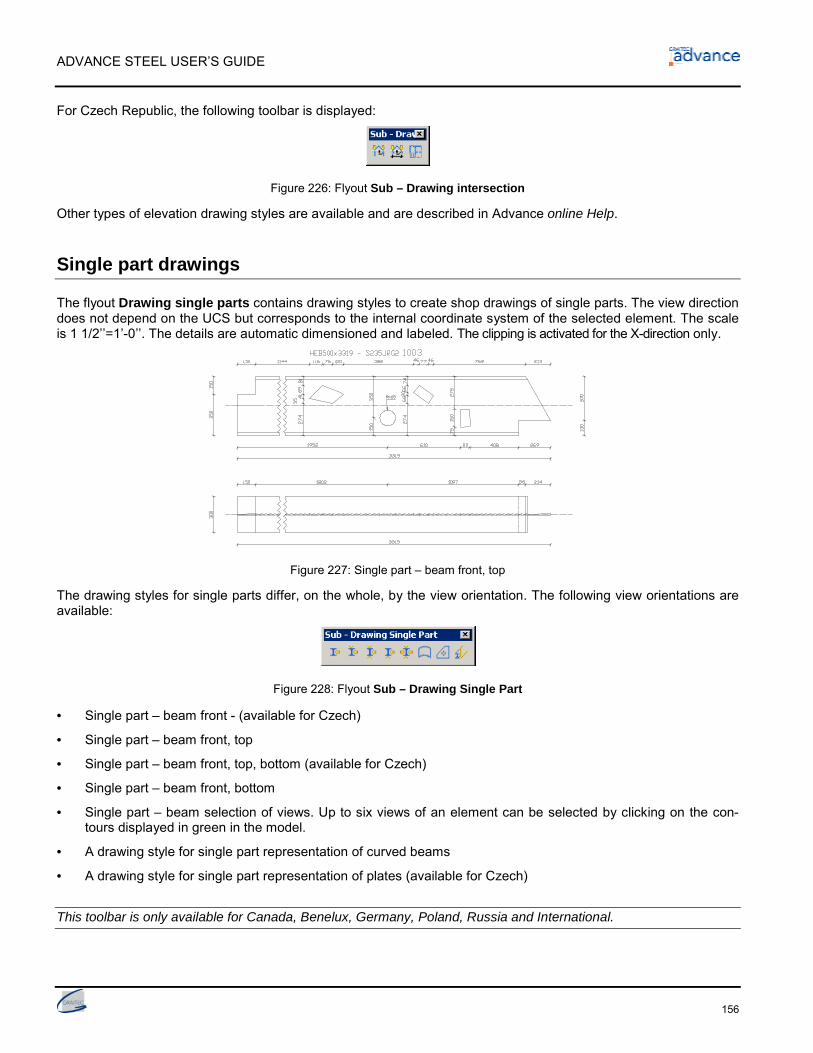
ADVANCE STEEL USER’S GUIDE
156
For Czech Republic, the following toolbar is displayed:
Figure 226: Flyout Sub – Drawing intersection
Other types of elevation drawing styles are available and are described in Advance online Help.
Single part drawings
The flyout Drawing single parts contains drawing styles to create shop drawings of single parts. The view directiondoes not depend on the UCS but corresponds to the internal coordinate system of the selected element. The scaleis 1 1/2’’=1’-0’’. The details are automatic dimensioned and labeled. The clipping is activated for the X-direction only.
Figure 227: Single part – beam front, top
The drawing styles for single parts differ, on the whole, by the view orientation. The following view orientations areavailable:
Figure 228: Flyout Sub – Drawing Single Part
• Single part – beam front - (available for Czech)
• Single part – beam front, top
• Single part – beam front, top, bottom (available for Czech)
• Single part – beam front, bottom
• Single part – beam selection of views. Up to six views of an element can be selected by clicking on the con-tours displayed in green in the model.
• A drawing style for single part representation of curved beams
• A drawing style for single part representation of plates (available for Czech)
This toolbar is only available for Canada, Benelux, Germany, Poland, Russia and International.

ADVANCE STEEL USER’S GUIDE
157
For USA, another drawing style for single part representation of folded plates is available:
Button FunctionSingle part – Folded plate
Tie beam
The drawing style in the flyout Drawing tie beam allows the creation of shop drawings for non-vertical main parts.The view direction does not depend on the UCS but corresponds to the internal coordinate system of the selectedmain part. The views are displayed with default scale 1 1/2’’=1’-0’, labeled and dimensioned. The clipping is acti-vated in the X-direction.
The drawing styles for tie beams differ, on the whole, by the assigned view orientation.
Figure 229: Flyout Sub – Drawing Tie Beam
• Tie beam – front
• Tie beam – front, top (available for Czech)
• Tie beam – front, top, bottom (available for Czech)
• Tie beam – front, bottom
• In drawing style “Tie beam –selection of views” up to 6 views can be selected. Click on the required contours,displayed in green in the model.
• In the drawing style “Tie beam –with environment” click on one or more connected elements that are then dis-played. Main parts are displayed from front and top, end plates from inside, and additional intersections fromthe right.
This toolbar is only available for Canada, Benelux, Germany, Poland, Russia or USA and International.
Columns
With the drawing style for columns, shop drawings for vertical elements can be created. The view direction does notdepend on the UCS but corresponds to the internal coordinate system of the selected main part. Columns can bedetailed as per tie beams but turned through 90 degrees – i.e. vertically.
The default scale is 1 1/2’’=1’-0’’ and an automatic dimensioning and labeling is done. The clipping is activated inthe X-direction.
The drawing styles for columns differ, on the whole, by the assigned view orientation.
Figure 230: Flyout Sub – Drawing Column

ADVANCE STEEL USER’S GUIDE
158
• Column – front
• Column – front, left
• Column – front, left, right (available for Czech)
• Column – front, right (available for Czech)
• In the drawing style “Column –seclection of views”, up to 6 views can be selected. Click on the required con-tours, displayed in green in the model.
• In the drawing style “Column –with environment”, select one or more connected elements to be displayed.Main parts are displayed from front and top, end plates from inside, and additional intersections from the right.
This toolbar is only available for Canada, Benelux, Germany, Poland, Russia or USA and International.
Assembly drawings
These styles create assembly shop drawings that depend on the current UCS orientation. The parts to be detailedshould be connected with shop connections. The scale is 1 1/2’’=1’-0’’ and the details are automatic dimensionedand labeled. The clipping is activated for the X-direction. Intersections at given places can be created by selectingthe green contours that are always perpendicular to the main part.
In the flyout Sub – Drawing main part, three styles are implemented.
Figure 231: Flyout Sub – Drawing Main Part
• “Main part –ucs displays” a main part so it is orientated in the drawing as in the model (see example above).Intersections can be selected with the green contours in the model; the view orientation runs against the posi-tive Z-axis of the UCS.
• The style “Intersection at ucs with selected parts” creates any cross section of the selected part at the currentUCS labeled with part numbers and leader lines.
• The style “Main part – curved beam” creates a view for a curved beam with dimensioning and labeling. Therepresentation does not depend on the current UCS.
• One more drawing style is available for Czech: “Main part - weldment section UCS single”.
This toolbar is only available for Canada, Benelux, Germany, Poland, Russia or USA and International.
To obtain an automatic internal view of the end plate or cover plates these must have the Model Role cover, base orend plate (Advance Properties, Note tab).

ADVANCE STEEL USER’S GUIDE
159
Special structural parts
The following styles are available in the flyout Sub – Drawing Special Structural Parts:
Figure 232: Flyout Sub –Drawing Special Structural Parts
• Compression pipe
• Cross bracing
• Tube development – template
• Tube development – template with tube
• Railing (not available for USA)
• Picket Railing (not available for USA)
• Stringer (not available for USA)
• ZED purlin
• Static plan, complete (not available for USA and Canada)
• Static plan, clipping (not available for USA and Canada).
This toolbar is only available for Benelux, Germany, Poland, Russia or International.
These styles are for elements that need a special representation or work with several Model Roles. The propertyModel Role can be created for each element in the Note tab of its dialog box and is interpreted by the program forfunctions such as drawing creation.
The drawing styles “Static plan complete” and “Static plan clipping” create model overviews with system lines.
For France the flyout Sub – Drawing Special Structural Parts contains three more drawing styles:
Figure 233: Flyout Sub – Drawing Special Structural Parts
• Single part – beam development
• Single part – bent beam
• Main part – bent beam
For USA, an additional toolbar contains drawing styles for stairs and railings:
Figure 234: Flyout Sub – Drawing Stairs Railings
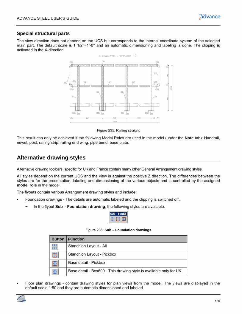
ADVANCE STEEL USER’S GUIDE
160
Special structural partsThe view direction does not depend on the UCS but corresponds to the internal coordinate system of the selectedmain part. The default scale is 1 1/2’’=1’-0’’ and an automatic dimensioning and labeling is done. The clipping isactivated in the X-direction.
Figure 235: Railing straight
This result can only be achieved if the following Model Roles are used in the model (under the Note tab): Handrail,newel, post, railing strip, railing end wing, pipe bend, base plate.
Alternative drawing styles
Alternative drawing toolbars, specific for UK and France contain many other General Arrangement drawing styles.
All styles depend on the current UCS and the view is against the positive Z direction. The differences between thestyles are for the presentation, labeling and dimensioning of the various objects and is controlled by the assignedmodel role in the model.
The flyouts contain various Arrangement drawing styles and include:
• Foundation drawings - The details are automatic labeled and the clipping is switched off.
− In the flyout Sub – Foundation drawing, the following styles are available.
Figure 236: Sub – Foundation drawings
Button FunctionStanchion Layout - All
Stanchion Layout - Pickbox
Base detail - Pickbox
Base detail - Box600 - This drawing style is available only for UK
• Floor plan drawings - contain drawing styles for plan views from the model. The views are displayed in thedefault scale 1:50 and they are automatic dimensioned and labeled.

ADVANCE STEEL USER’S GUIDE
161
Figure 237: Flyout Sub – Floor plan drawings
There are two floor plan drawing styles available in the flyout Floor plan drawings:
Button Function
Floor plan - hot rolled - all
Floor plan - Hot rolled - PickBox: the xy viewport is selected with the mouse
For UK, two more drawing styles are available:
Button FunctionFloor plan - cold rolled - all
Floor plan - cold rolled - PickBox
• Roof plan drawings - The views are displayed in the default scale 1:50 and the details are automatic dimen-sioned and labeled. The clipping is switched off.
Figure 238: Flyout Sub – Roof Plan Drawings
The following drawing styles are available in the flyout Roof plan drawings:
Button FunctionRoof plan - hot rolled - all
Roof plan - hot rolled - pickbox
Roof plan - Cold rolled - All
Roof plan - Cold rolled - Pickbox
• Elevation drawings - contain drawing styles for elevation drawings. The views are displayed in the default scale1:50 and the details are automatic dimensioned and labeled.
Figure 239: Flyout Sub – Elevation drawings
The following drawing styles are available in the flyout Elevation drawings:
Button FunctionElevation - Side - Hot Rolled - All
Elevation - Side - Hot Rolled - Pick Box

ADVANCE STEEL USER’S GUIDE
162
Button FunctionElevation - Gable - Hot Rolled - All
Elevation - Gable - Hot Rolled - Pick Box
For UK, two more drawing styles are available:
Button FunctionElevation - Cold rolled - All
Elevation - Cold rolled - PickBox
• Section drawings - contain drawing styles for sections from the model. The views are automatic dimensionedand labeled.
Figure 240: Sub – Section drawings
There are three section drawing styles available in the flyout Section drawings
Button FunctionSection - all - xy viewport - automatic
Section - pickbox: the xy - viewport is selected with the mouse
Section - select: only selected elements are detailed
Section - box1000 - This drawing style is available only for UKcountry AddIn
• 3D drawings - contain drawing styles for 3D drawings of the entire model or of selected part. The clipping isswitched off and the default scale is 1:50.
Figure 241: Sub – 3D Drawings
The following drawing styles are available:
Button Function3D view - All - no labels
3D view - All - with labels
3D view - Select - no labels
3D view - Select - with labels
3D - View - Select+PickBox - no labels
3D - View - Select+PickBox - with labels

ADVANCE STEEL USER’S GUIDE
163
Processes
Advance drawing processes are used to accelerate drawing creation by automatic assigning drawing styles andlayouts for the selected parts.
A process includes a number of sub processes: the selection of parts, the sorting, drawing style selection, rules forarranging details on the sheet and rules to attach new sheets.
The default processes are located within the main-toolbar Numbering, drawing according to the formats A0, A1,A2, A3 and A4 and are accessible in the flyouts by the corresponding icons.
Figure 242: Main-toolbar Numbering, drawing, processes
For each format, e.g. A0, the same series of selection groups are available. The selection groups shown for theformat A0 recur for the formats A1, A2, A3, and A4.
Drawing processesThe following flyout/tools are available for each drawing size format:
Figure 243: Processes - selection per format
• All single parts
• All single parts plate
• All single parts beam
• All main parts
• All main parts plate
• All main parts beam
• All main parts with attached parts
• All cameras
• Selected single parts
• Selected single parts plate
• Selected single parts beam
• Selected main parts
• Selected main parts plate
• Selected main parts beam
• Selected main parts with attached parts
• Selected cameras.
For each different part number, a detail is created so no duplicate drawings are created.
Within a process, a specific sorting can be entered in the dialog-box.

ADVANCE STEEL USER’S GUIDE
164
Advance offers specific drawing styles that support full automatic drawing creation. These styles differ mainly fromother styles in that the title text includes the number of pieces in the model, or in the case of single parts the numberof pieces on the main-part are also displayed. Intersections are created automatic.
The automatic drawing creation is managed by the Document Manager where they are listed, displayed, and if re-quired, updated and deleted.
Example: Automatic detailing of all main parts in a model with attached parts (A0)
• After the model has been checked and numbered, start the automatic detailing process for all main parts(including their attached parts), with the tool “Main parts with attached parts”, from the toolbar (flyout) A0 inthe Advance main-toolbar Numbering, drawing. The dialog-box Process properties pops up.
Figure 244: Processes: Dialog-box Process properties
• Set the drawing number options for the drawings created by the process: the first number and the increase value.
• Besides the selection, you can enter information for arrangement. Choose a selection if required and confirm withOK.
Figure 245: Drawing processes, sorting
The details are created and placed in the drawing.
• The detail drawings for all beams are created automatic. In the Document Manager each linked beam detail islisted and attached to the same DWG, e.g. ...\Program\GRAITEC\AdvanceSteel\Work\Projectname\details\A0-Detail00001.dwg. When the drawing is full a new drawing A0 detail 00002 is attached.
• In the Preview field of the Document Manager you can see a previews of detail drawings.
• Open the drawing e.g. A0-Details 00001.dwg using File > Open in the top menu bar from AutoCAD®. Youwill see the individual details together on the drawing and can plot or edit the drawings.
• Close the DWG and go back to the model.

ADVANCE STEEL USER’S GUIDE
165
For the formats A0, A1, A2, many details are located on the sheet until it is full. Then a new drawing is started. Forthe formats A3 and A4, the details are placed on individual sheets.
The details are automatic located on the sheet by the process. Before starting the process you can change the ar-rangement direction on the sheet. This must be done in the prototype drawing using the tool “Define drawing layout”in the flyout Sub – Drawing management.
CamerasThe creation of drawing views and elevations has been considerably improved and made faster by the Advancecamera design.
The camera is an object representing the location, angle and depth of a view, allowing individual focus for automaticcreation of detail drawings. With the cameras model views, elevations or overview settings and node details can bepresented, named and saved.
The cameras can also be used in processes for automatic creation of details. Two of the automatic detailing proc-esses in Advance refer to cameras:
• Create detail drawings from all cameras
• Create detail drawings of selected cameras
Tools for defining different cameras are accessible in the Advance Standard-toolbar, flyout Sub – Create cameras.
Figure 246: Flyout Sub – Create cameras
• Create camera (ucs): With this tool, elevations / views are set in the model for use later on in detailing.
• Create camera(s) at node: With the camera at node details, six cameras can be set at joints. These correspondto the six view directions of the details and can be set for use later on in detailing.
Create camera (UCS)A camera is created according to the current user coordinate system. The view direction runs against the Z-axis andthe size of the clipping can be determined with a detail box with X/Y/Z-depth. The size of the clipping can be deter-mined with a detail box with X/Y/Z-depth.
• To define a camera of this type, determine the view direction on the object by setting a corresponding UCS.
• Then enter an origin for the camera.
• The Camera dialog-box pops up in which a camera type (no, node, overview) can be entered. This informa-tion is important so the camera process can distinguish between overview and node.
Figure 247: Create camera (UCS)

ADVANCE STEEL USER’S GUIDE
166
The grid is stretched around the set origin, which is at the center, and the size of the grid is determined by thevalues in the detail box. The positive and negative Z-values refer to the clipping distance in front and behindthe grid on the UCS plane. The pencil-top shows the view direction against the positive Z-axis.
Figure 248: Dialog-box Camera
Create camera (s) at nodeThis node–camera tool is specifically modified for the Advance joints and determines the orientation and the size of node views.
For the detail presentation of a node, one or more cameras with different view directions are created at a connec-tion object. The user has the choice between six cameras with different colors.
Note: The connection object (gray box) must be visible so it can be identified in the command course.
• To define one or more node cameras, display the connection object(s) and then start the tool “Create camera(s) at node”.
• Six different colored cameras appear. They are created with a standard detail box size. The size of the box andother Properties can be changed later in the Properties dialog-box of the created camera.
• Select one or more cameras on the screen and return to confirm. The selected cameras are displayed in blueand the others disappear.
The corresponding drawing processes can interpret the created cameras.
Alternative Drawing ProcessesAlternative “Drawings” toolbars contain many additional drawing processes for each country.
Examples:
Process ANSI-A
Figure 249: Flyout Sub – Process ANSI-A
A0 drawings
Figure 250: Flyout Sub – A0 Drawings
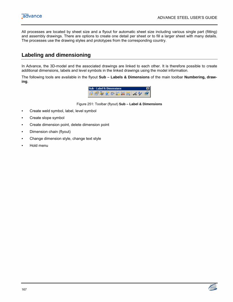
ADVANCE STEEL USER’S GUIDE
167
All processes are located by sheet size and a flyout for automatic sheet size including various single part (fitting)and assembly drawings. There are options to create one detail per sheet or to fill a larger sheet with many details.The processes use the drawing styles and prototypes from the corresponding country.
Labeling and dimensioning
In Advance, the 3D-model and the associated drawings are linked to each other. It is therefore possible to createadditional dimensions, labels and level symbols in the linked drawings using the model information.
The following tools are available in the flyout Sub – Labels & Dimensions of the main toolbar Numbering, draw-ing.
Figure 251: Toolbar (flyout) Sub – Label & Dimensions
• Create weld symbol, label, level symbol
• Create slope symbol
• Create dimension point, delete dimension point
• Dimension chain (flyout)
• Change dimension style, change text style
• Hold menu
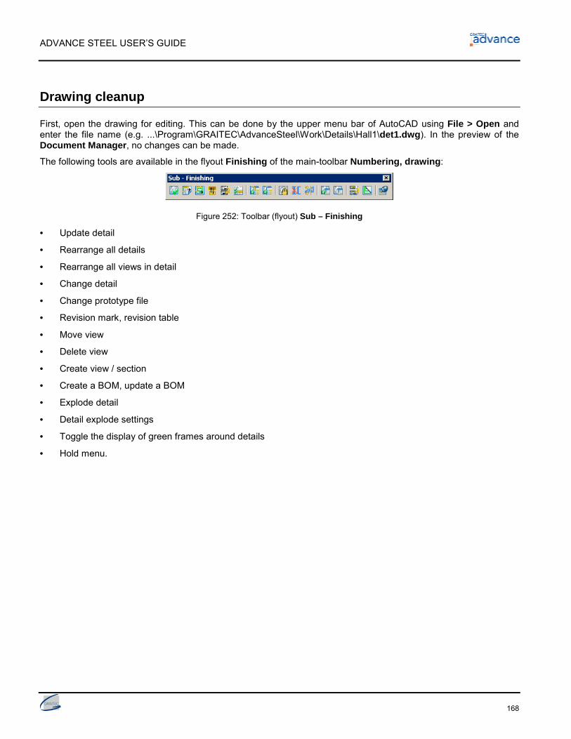
ADVANCE STEEL USER’S GUIDE
168
Drawing cleanup
First, open the drawing for editing. This can be done by the upper menu bar of AutoCAD using File > Open andenter the file name (e.g. ...\Program\GRAITEC\AdvanceSteel\Work\Details\Hall1\det1.dwg). In the preview of theDocument Manager, no changes can be made.
The following tools are available in the flyout Finishing of the main-toolbar Numbering, drawing:
Figure 252: Toolbar (flyout) Sub – Finishing
• Update detail
• Rearrange all details
• Rearrange all views in detail
• Change detail
• Change prototype file
• Revision mark, revision table
• Move view
• Delete view
• Create view / section
• Create a BOM, update a BOM
• Explode detail
• Detail explode settings
• Toggle the display of green frames around details
• Hold menu.

Appendix


ADVANCE STEEL USER’S GUIDE
171
HSBasis
Command Description
AstModelBrowser Access Model BrowserAstM4CommProjectData Definition of the project information, units and preferencesAstM5PrefixConfigurationExplorer Prefix configurationAstDocCheck Start the Document ManagerAstM4About Displays AdvanceSteel About dialogAstM4BeamContourNotchCircle1Dig Beam processing - Circular contour by center pointAstM4BeamContourNotchCircle2Dig Beam processing - Circular contour by two pointsAstM4BeamContourNotchPolygon Beam processing - Polygonal contourAstM4BeamContourNotchRect1Dig Beam processing - Rectangular contour cutAstM4BeamContourNotchRect2Dig Beam processing - Rectangular contour by two pointsAstM4Cecs UCS at objectAstM4ChangeBindingLength Calculate grip lengthAstM4changerep Change the presentation typeAstM4CommAstorToCIS2 Export CIS/2AstM4CommAudit Extend the AutoCAD audit checking to include AdvanceSteel objectsAstM4CommBatchErrorsMarkObject Display the checking resultsAstM4CommBatchErrorsPrint Display the checking results againAstM4CommCIS2ToAstor Import CIS/2AstM4CommClipCrossSection Create a beam cross sectionAstM4CommCrBeamBent Create a curved beamAstM4CommCrBeamPoly Convert a polyline to a polybeamAstM4CommCreateAssemblyMainPart Create the assembly partAstM4CommCreateConnection_AstM4CommCreateConnection INCL Connection, add objects_AstM4CommCreateConnection EXCL Connections, disconnect objectsAstM4CommCreateMainPart Create main part of assemblyAstM4CommCutPlateToPlate Miter platesAstM4CommDSTVStaticIn_AstM4CommDSTVStaticIn NORMAL Statics read_AstM4CommDSTVStaticIn INVERT Statics read, WCS invertedAstM4CommExplodeCombiProfile Disassemble compound sectionsAstM4CommGotoMark Zoom to highlighted objectAstM4CommGridAxes Create a group of four axesAstM4CommGridAxesSequences Create a group of axes specifying the distancesAstM4CommGridDeleteAxis Delete the selected axis from the gridAstM4CommGridExtend Extend grid axisAstM4CommGridInsertSequence Create a group of axes after the selected axis
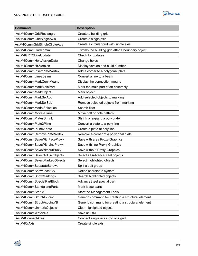
ADVANCE STEEL USER’S GUIDE
172
Command Description
AstM4CommGridRectangle Create a building gridAstM4CommGridSingleAxis Create a single axis
AstM4CommGridSingleCircleAxis Create a circular grid with single axis
AstM4CommGridTrimm Trimms the building grid after a boundary objectAstM4GRTCLiveUpdate Check for updatesAstM4CommHoleAssignData Change holesAstM4CommHSVersion Display version and build numberAstM4CommInsertPlateVertex Add a corner to a polygonal plateAstM4CommLine2Beam Convert a line to a beamAstM4CommMarkConnMeans Display the connection meansAstM4CommMarkMainPart Mark the main part of an assemblyAstM4CommMarkObject Mark objectAstM4CommMarkSelAdd Add selected objects to markingAstM4CommMarkSelSub Remove selected objects from markingAstM4CommModelSelection Search filterAstM4CommMove2Plane Move bolt or hole patternAstM4CommPlatesShrink Shrink or expand a poly plateAstM4CommPlate2Pline Convert a plate to a poly lineAstM4CommPLine2Plate Create a plate at poly lineAstM4CommRemovePlateVertex Remove a corner of a polygonal plateAstM4CommSaveWithFaceProxy Save with area Proxy-GraphicsAstM4CommSaveWithLineProxy Save with line Proxy-GraphicsAstM4CommSaveWithoutProxy Save without Proxy-GraphicsAstM4CommSelectAllDscObjects Select all AdvanceSteel objectsAstM4CommSelectMarkedObjects Select highlighted objectsAstM4CommSeparateScrews Split a bolt groupAstM4CommShowLocalCS Define coordinate systemAstM4CommShowMarkings Search highlighted objectsAstM4CommSpecialPartBlock AdvanceSteel special partAstM4CommStandaloneParts Mark loose partsAstM4CommStartMT Start the Management ToolsAstM4CommStructAsJoint Generic command for creating a structural elementAstM4CommStructAsJointVB Generic command for creating a structural elementAstM4CommUnmarkObjects Clear highlighted objectsAstM4CommWrite2DXF Save as DXFAstM4ConnectAxes Connect single axes into one gridAstM4CrAxis Create single axis

ADVANCE STEEL USER’S GUIDE
173
Command Description
AstM4CrBeamByClass Generic command for creating straight beams with specific section class_astm4crbeambyclass I Create a beam with a rolled I section_astm4crbeambyclass U Create a beam with chanel section_astm4crbeambyclass W Create a beam with angle section_astm4crbeambyclass T Create a beam with T-section_astm4crbeambyclass O Create a beam with Circular hollow section_astm4crbeambyclass Z Create a beam with Z section_astm4crbeambyclass F Create a beam with flat section_astm4crbeambyclass D Create a round bar_astm4crbeambyclass Q Create a square bar_astm4crbeambyclass H Create a square hollow section_astm4crbeambyclass C Create a cold rolled section_astm4crbeambyclass A Create other sectionAstM4CrBeamContourNotch Create a contour cope on a beamAstM4CrBeamMFC Create a beamAstM4CrBeamMiterCut Miter cut for two beamsAstM4CrBeamNotch Cope at a beam endAstM4CrBeamShort Create a beam shortenAstM4CrBeamShortUCS Create a beam shorten at the UCSAstM4CrCompBeam Old compound sectionAstM4CrCompoundBeam_AstM4CrCompoundBeam WeldedISymmet-ric Default
Create a welded beam I symmetric
_AstM4CrCompoundBeam WeldedIAsym-metric Default
Create a welded beam I asymmetric
_AstM4CrCompoundBeam WeldedHollowDefault
Create a welded beam hollow
_AstM4CrCompoundBeam WeldedT Default Create a welded beam T_AstM4CrCompoundBeam WeldedColumnDefault
Create a welded beam, column
_AstM4CrConByVb TaperedBeam Create a tapered welded beamAstM4Create1DigChamfer Create a chamfer with one pointAstM4Create2DigChamfer Create a chamfer with two pointsAstM4CreateConcavFillet Create a concave corner finishAstM4CreateConvexFillet Create a convex corner finishAstM4CreatePolyPlate Create a polygon plate by specifying the corner pointsAstM4CreateRect1DigPlate Create a rectangular plate by specifying the center pointAstM4CreateRect2DigPlate Create a rectangular plate by specifying two pointsAstM4CrRaster Create a building gridAstM4CrSequPar Create parallel axis groupAstM4CrStruct3GFrameSymm Create a 3-hinged frame, symmetric

ADVANCE STEEL USER’S GUIDE
174
Command Description
AstM4CrStructMultiFrame_AstM4CrStructMultiFrame DEF
Create purlins
AstM4CrStructMultiTowerFrame_AstM4CrStructMultiTowerFrame DEF
Create pylons
AstM4CrStructSingleFrameBracing_AstM4CrStructSingleFrameBracing DEF
Create a single-span bracing
AstM4CrStructSlopeFrame_AstM4CrStructSlopeFrame DEF
Create a half truss
AstM4Database Statics write totalAstM4FoldedPlateCheckUnwinding Check unfoldingAstM4FoldedPlateExtend Create a folded plateAstM4FoldedPlateSetMain Set folded plate main objectAstM4HeightKote Create a level symbolAstM4HelpCommand Access helpAstM4PlateContourNotch_AstM4PlateContourNotch RECTANGLE Plate processing UCS - rectangular contour by center_AstM4PlateContourNotch RECTAN-GLE2DIG
Plate processing UCS - rectangular contour by two points
_AstM4PlateContourNotch CIRCLE Plate processing UCS - circular contour by center_AstM4PlateContourNotch CIRCLE2DIG Plate processing UCS - circular contour by two points_AstM4PlateContourNotch POLYGONE Plate processing UCS - polygonal contour
AstM4PlateInnerContour_AstM4PlateInnerContour RECTANGLE Plate processing - rectangular contour by center_AstM4PlateInnerContour RECTAN-GLE2DIG
Plate processing - rectangular contour by two points
_AstM4PlateInnerContour CIRCLE Plate processing - circular contour by center_AstM4PlateInnerContour CIRCLE2DIG Plate processing - circular contour by two points_AstM4PlateInnerContour POLYGONE Plate processing - polygonal contourAstM4PSSDirect Export SteelfabAstM4RemoveHyperSteel Delete all AS objects from external dwgAstM4ReopenDatabase Update defaultsAstM4SelectObjectByName Select AdvanceSteel objectsAstM4SsetDatabase Statics write selectionAstM4SwitchReprMode Hide or show objectsAstM4UndoSwitch Disable or enable UNDOAstM4WeldSeam Generic command for the creation of welds_AstM4WeldSeam POINT Create a weld point_AstM4WeldSeam STRAIGHT Create a weld lineAstM5BoltsHolesSwitchConnector Switch to shear studsAstM5BoltsHolesSwitchHoles Switch to bolts / holes / shear studsAstM5CommBoltsHolesAllSides Create bolt or holes rectangular pattern set by 2 points

ADVANCE STEEL USER’S GUIDE
175
Command Description
AstM5CommBoltsHolesCircle Create bolt or holes circular pattern set by the center pointAstM5CommBoltsHolesLLSides Create a rectangular pattern set by the corner pointAstM5CommBoltsHolesRect Create a rectangular pattern set by the center pointAstM5CommCamera Create camera, UCSAstM5CommCameraNode Create camera(s) at nodeAstM5CommEcsAtPickPoint UCS at curved beamAstM5CommEqualPartsOnePartOutOf Select objects with different part numbersAstM5CommEqualPartsWithoutNum Mark parts without numberAstM5CommSemanticCheck Steel construction technical checkingAstM5DetSetArranger Define drawing layoutAstM5EqualPartsChangePrefix Assign or change the prefixAstM5EqualPartsCheck Identify the objects with duplicate part numbersAstM5EqualPartsCheckGroups Check for duplicate part numbersAstM5EqualPartsDelNumber Delete part numbersAstM5EqualPartsDetect NumberingAstM5EqualPartsMarkSame Display objects with identical part numberAstM5EqualPartsReset Ungroup identical partsAstM5EqualPartsShowDiff Differences between two objects (pos check)AstM5EqualPartsSwitchMain Switch to mainpart numberingAstM5EqualPartsSwitchSingle Switch to singlepart numberingAstM4LoadSTEP Write SDDPAstM4CrBisectorCS Set the UCS to the bisecting lineAstM4CommExplodeToAcis Explode object to ACISAstM4CommBevelWeldingPreparation Weld seam preparation, chamferAstM4CommFilletWeldingPreparation Weld seam preparation, filletAstM4CutPlateAtUcs Cut plate at UCSAstM4CutPlateAtPlate Cut plate at an other plateAstM4CommUserSectionBeam Create a folded beamAstM4CommBillOfMaterial Create listsAstM4CommStartConcrete Start Advance ConcreteAstM4UCSZFilter Switch for working 2D / 3D (for snap points)AstProcessesSuite Drawing process suiteASTransform Select the transformation typeASTransformAndConnect Advance Copy tools

ADVANCE STEEL USER’S GUIDE
176
HSDetailing
Command DescriptionAstM4DetRegist Register a detail to the modelAstM4DetDeregist Deregister a detail from a model
HSConnection
Command DescriptionAstM4CrConByRule Generic command for creating a jointAstM4CrConByRule 1 ParamFit Cope parametric ruleAstM4CrConByRule 1 Saw_1 Cut at object – ruleAstM4CrConByRule 1 SawAngle_Asym Cut variable – ruleAstM4CrConByVB General command for creating a jointAstM4CreateGussetPlate Create a gusset plateAstM4TransferCons Create by template (intelligent connections)AstM4TransferParams Transfer properties (intelligent connections)AstM4UpdateConOb_AstM4UpdateConOb UPDATE Update a joint_AstM4UpdateConOb DELETE Delete a jointAstM4UserTemplateConn_AstM4UserTemplateConn _c Create template connection_AstM4UserTemplateConn _i Import template connection
HSExtended
Command DescriptionAstM4CrBeamElemContNotch Element contour - exact cross sectionAstM4PlateElementContourNotch Plate processing by element contourAstM4CommMergeBeams CONVERT sectionsAstM4CommMergePlates CONVERT platesAstM4CommSeparateBeams Split beamsAstM4CommSeparatePlates Split plates at linesAstM4CommSeparatePlate Split plates by two pointsAstM4CommDeepExplode Explode a joint and all subjoints
HSCollision
Command DescriptionAstM4Balancepoint Center of gravity and total weight calculationAstM4CheckCollision Clash check between selected objects

ADVANCE STEEL USER’S GUIDE
177
HSDetailingBasis
Command DescriptionAstM4CommDetRevisionTable Revision tableAstM4DetChange Change detailAstM4CommDetAddHorLinearDim Linear horizontal dimensionAstM4CommDetAddSlopeLinearDim Linear sloped dimensionAstM4CommDetAddVertLinearDim Linear vertical dimensionAstM4CommDetArrangeDetails Rearrange all detailsAstM4CommDetArrangeViews Rearrange all views in detailAstM4CommDetUpdateDetail Update detailAstM4DetManualCut Create view / sectionAstM4CommDetailRevision Revision markAstM4CommExplodeDetail Detail explode settingsAstDetCheck Check details statusAstM5DetailStylesExplorer Drawing Style ManagerAstM5DetailStylesManagerNew Start the new Drawing Style ManagerAstM4CommDetAddDim General dimensionAstM4CommDetAddDimSlope Create slope symbolAstM4CommDetAddDimAngle Angle dimensionAstM4CommDetAddDimArc Arc dimensionAstM4CommDetAddDimRadial Radial dimensionAstM4CommDetByStyle 3D viewAstM4CommDetailing Generic command for caling detail stylesAstM4CommDetailingProc Generic command for calling processesAstM4CommDetCrHeightKote Create a level symbolAstM4CommDetCrWeldSeam Create a weld symbolAstM4CommDetAddAnnotation User labelAstM4CommDetInsertAnno Create labelAstM4CommDetModDimAdd Create dimension pointAstM4CommDetModDimRemove Delete dimension pointAstM4CommDetModDimStyle Change dimension styleAstM4CommDetModTextStyle Change text styleAstM4CommDetUpdateBOM Update listsAstM4CommDetSwitchHighlightState Toggle the display of green frames around detailsAstM4DetViewDelete Delete ViewAstM4DetViewTransform Move viewAstM5DetailProcessExplorer Start the Drawing Process ManagerAstM4CommDetAddHorLinearDim Linear horizontal dimensionAstM4CommDetAddSlopeLinearDim Linear sloped dimensionAstM4CommDetAddVertLinearDim Linear vertical dimension

ADVANCE STEEL USER’S GUIDE
178
Command DescriptionAstM4CommDetInsertBom Create a list
HSDetailing
Command DescriptionAstM4CommDetAddDimArc Arc dimensionAstM4DetProc ProcessesAstM4CommDetInsertBom Create a listAstM4CommChangePrototype Change prototype file
HSIFDSTVBOM
Command DescriptionAstM4CommPSSOut Write PSS
HSIFDSTVNC
Command DescriptionAstM4CommPSSOut Write PSSAstM4CommCreateNCByStyle HSIFDSTVNC NC, DXF (plates), DXF (all objects)AstM4NCSettings NC Settings
HSIFPM (HSExtended)
Command DescriptionAstM4CommPSSIn Read PSSAstM4CommPSSOut Write PSSAstM4Astor2RepPSS Export PSS
HSSTAAD
Command DescriptionAstM4CommAstorToSTD Export STDAstM4CommSTDToAstor Import STD

Index

ADVANCE STEEL USER’S GUIDE
180
3D model, 28Access databases, 10Access-tables, 31Advance Management Tool, 10Advance properties, 73Advance Steel toolbar, 36Angle connections, 31Any contour, 66Any contour processing, 69, 70Apex, 94ARX-Technology, 9Assembly numbers, 122Assembly part, 127ASTemplate.dwt, 36Audit checking, 132AutoCAD specific properties, 41AutoCAD-Manipulating Tools, 72AutoCAD-properties, 73Auxiliary objects, 32Axis groups, 44Base plate, 31Basic object, 29Beam processing, 29, 63Beam to column, 92Beams, 28Behavior, 48, 76Bolt pattern, 30Bolt patterns, 76Bolts, 77Building grid, 44Buttons, 39Camera, 165Checks, 130, 134Circular contour, 66Circular processing, 70Circular processing object, 69Collision check, 131Collision solids, 131Colors, 42Compound sections, 46, 48Compression pipe, 100Connection, 81Connection object, 64, 89, 113Construction systems, 9, 52Contour element, 69Curved beams, 49Cut at object, 65Cut variable, 65Default values, 10Diagonal bracing, 31Dialog-box, 40Display connected object, 82Display connecting elements, 82Display objects connected in shop, 82Document Manager, 8, 145, 149Double-sided web joint, angle-end plate, 95
Drawing formats, 146Drawing frames, 146Drawing style, 144Drawing styles, 10Drawings, 144DWG, 8Element contour, 66Elevations, 155End plates, 31End plates, asymmetrical, 96Esc –key, 40Extract, 138F2 –key, 40Features, 29Flat bracings, 31Flat frames, 86Flyouts, 36Frame corners, 31Gable columns/posts, 93Gable wall connections, 31Geometric Properties, 41Gravity axis, 47Grid axes, 32Grid values, 72Grips, 72, 74Gusset plate connection, 96, 97Gusset plates, 31, 56Hide objects, 85Hole pattern, 76, 78Holes, 30HSS bracings, 31Insertion axis, 47Joint, 30Joints, 30, 89Joist, 86Layer, 42Level symbols, 32List Template Wizard, 138, 140Main part, 127MDI, 10MFC, 10Model, 8Model changes, 8Model objects, 138, 139Model role, 87Moment end plate, 93Moment end plate connection, 96Node, 154Non-vertical main parts, 157Numbering, 122Object coordinate system, 60Objects, 8ODBC, 10PCS (Program system in the steelconstruction), 10Pin-Ended Column, 93

ADVANCE STEEL USER’S GUIDE
181
Pin-ended columns connections, 31Plate processing, 29, 67Plate splice, 94Plates, 28, 53Platform connections, 31Platform splices, 96Poly beams, 46, 50Polygon plate, 55PPS (Interface product of the steelconstruction), 10Presentation types, 74Processes, 145Processing based on rules, 64Processing contours, 29Processing object, 63Project information, 153Properties, 41Proxy-graphics, 10Purlin, 86Pylons, 86Rectangular contour, 66Rectangular plates, 54Rectangular processing, 69, 70Reference axes, 47Report, 141Representation type, 85Ridge connections, 31Search filter, 84Section classes, 46Selected objects on, 86Selecting objects, 83Shape, 48Shear plates, 31
Shear studs, 76, 78Shop drawings, 8, 157Shorten at UCS, 64Single part number, 122Single parts, 156Single-span bracings, 86Snaps, 74Special parts, 32, 114Splice joint, 94Splices, 31Standard toolbar, 37Steel construction checking, 133Stiffeners, 31Structural elements, 86Structural frame, 31Structured BOM, 140Structured BOM's, 8System line, 47Technical properties, 41Title block, 154Title blocks, 146Toolbars, 36Tube connections, 31Turnbuckle bracing, 31User Coordinate System (UCS), 59User sections, 115View, 147Web connections, 31Weld line, 80Weld point, 80Welded beams, 52Welds, 29World Coordinate System (WCS), 59

027107-0409S-0313
FranceGRAITEC France Sarl10bis Burospace91572 BièvresTel. 33 (0)1 69 85 56 22Fax 33 (0)1 69 85 33 70Web http://www.graitec.com/Fr/Email [email protected]
CanadaGRAITEC Inc.49 Rue de la Pointe-LangloisLaval (Québec) H7L 3J4Tel. (877) 464-3366Fax (450) 628 0400Hotline (877) 464-5046Web http://www.graitec.com/CaFr/Email [email protected]
USAGRAITEC Inc.Dallas / Forth WorthTel. (877) 464-3366Fax (450) 628 0400Hotline (877) 464-5046Web http://www.graitec.com/En/Email [email protected]
Germany, Switzerland, AustriaGRAITEC GmbHCentroallee 263aD-46047 Oberhausen GermanyTel. +49-(0) 208 / 62188-0Fax +49-(0) 208 / 62188-29Web http://www.graitec.com/Ge/Email [email protected]
RomaniaGRAITEC Roumanie SRLStr. Samuil Vulcan, Nr. 10 Sector 5Bucureşti, RomaniaTel. +40 (21) 410.01.19Fax +40 (21) 410.01.24Web http://www.graitec.com/Ro/Email [email protected]
Czech Republic and SlovakiaAB Studio spol. s r.o.Jeremenkova 90a 140 00 PRAHA 4Tel. +420/244 016 055Fax +420/244 016 088Hotline +420/244 016 050Web http://www.abstudio.cz/Email [email protected]
![Home [] · 2021. 2. 24. · samsung samsung samsung samsung samsung advance advance advance advance advance advance advance advance advance advance 223sw 2233sw 2233sw 2233sw 933sn](https://img.dokumen.tips/doc/110x75/613cd1974c23507cb6359ff0/home-2021-2-24-samsung-samsung-samsung-samsung-samsung-advance-advance.jpg)


![[John_Piper] velvet-steel.pdf](https://img.dokumen.tips/doc/110x75/577cc44a1a28aba71198cf9c/johnpiper-velvet-steelpdf.jpg)