Embed Size (px)
Citation preview
113
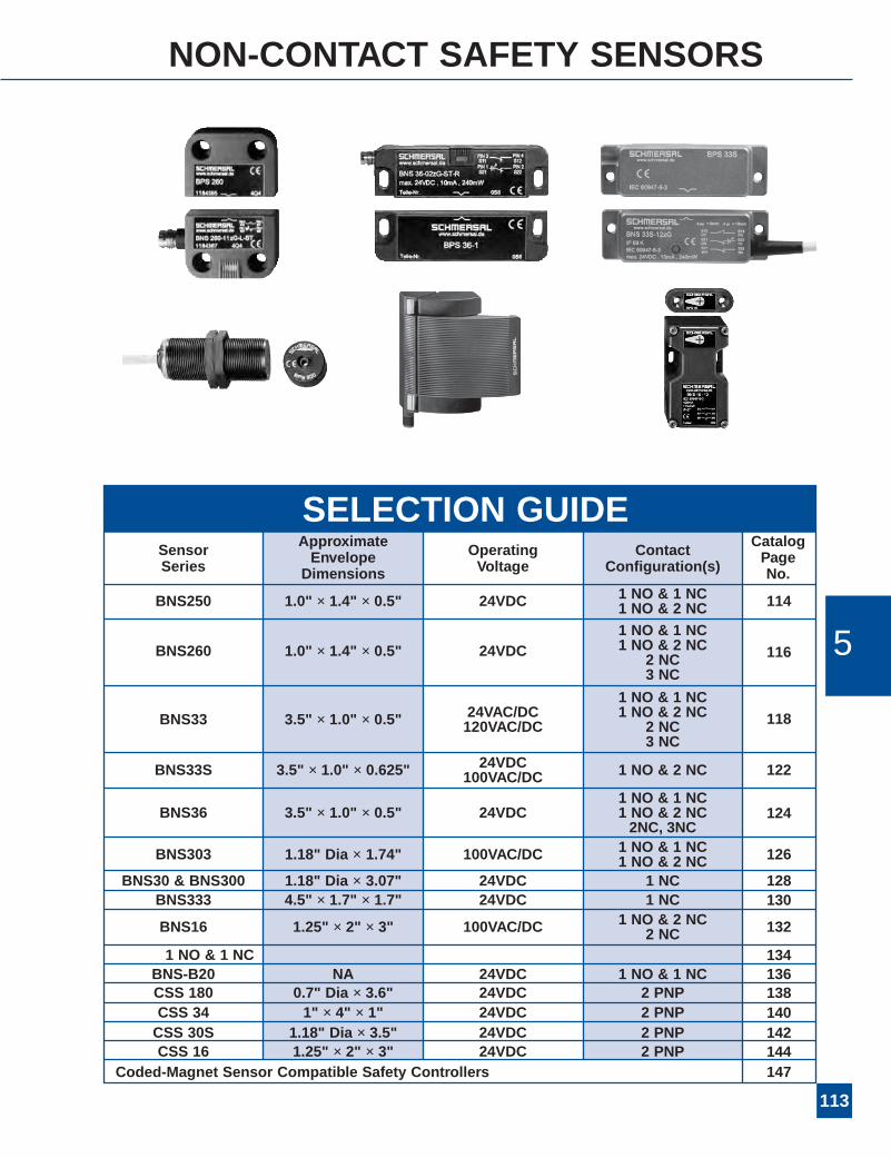
NON-CONTACT SAFETY SENSORS
BNS33S 3.5" × 1.0" × 0.625" 24VDC 1 NO & 2 NC100VAC/DC
SensorSeries
ApproximateEnvelopeDimensions
OperatingVoltage
ContactConfiguration(s)
CatalogPageNo.
BNS33 3.5" × 1.0" × 0.5"
1 NO & 1 NC24VAC/DC 1 NO & 2 NC120VAC/DC 2 NC
3 NC
BNS333 4.5" × 1.7" × 1.7" 24VDC 1 NC 130
118
122
BNS303 1.18" Dia × 1.74" 100VAC/DC 1 NO & 1 NC1 NO & 2 NC 126
128
BNS16 1.25" × 2" × 3" 100VAC/DC 1 NO & 2 NC2 NC
1 NO & 1 NC
Coded-Magnet Sensor Compatible Safety Controllers
132
134
CSS 180 0.7" Dia × 3.6" 24VDC 2 PNP 138BNS-B20 NA 24VDC 1 NO & 1 NC 136
147
BNS30 & BNS300 1.18" Dia × 3.07" 24VDC 1 NC
CSS 34 1" × 4" × 1" 24VDC 2 PNP 140CSS 30S 1.18" Dia × 3.5" 24VDC 2 PNP 142CSS 16 1.25" × 2" × 3" 24VDC 2 PNP 144
BNS250 1.0" × 1.4" × 0.5" 24VDC 1 NO & 1 NC1 NO & 2 NC 114
BNS260 1.0" × 1.4" × 0.5" 24VDC1 NO & 1 NC1 NO & 2 NC
2 NC3 NC
116
1 NO & 1 NCBNS36 3.5" × 1.0" × 0.5" 24VDC 1 NO & 2 NC
2NC, 3NC124
5
SELECTION GUIDE
114
SERIES BNS250 Coded-Magnet Sensors
AVAILABLE STANDARD MODELS(Please order BPS250 magnet separately)
DescriptionThe Series BNS250 coded-magnet sensors are designed foruse as a safety interlock switch on movable machineguards/articulating robot arms. Each sensor set consists of amultiple reed switch unit and a coded-magnet actuator. Thereed switches, wired in series, will only close in the presenceof their matched magnetic field array.
Both switch and magnet assemblies are sealed to IP67(submersible) standards. Their tamper-resistant designprevents bypassing with a simple magnet or improperly codedmagnetic field. In addition, the BNS module features a 1-meter long prewired pigtail.
OperationThe reed switch assembly is typically mounted to a stationaryportion of a guard structure, with the coded-magnet assemblymounted to the movable element of the machine guard. Whenthe guard is closed, and the matched magnetic field alignswith the reed switch unit, the switches will close. When theguard is open, or the required magnetic-field array is notproperly aligned with the reed switch assembly, the sensoroutput will remain “off.”
Typical ApplicationsThe sealed, compact BNS250 is ideal for use on movablemachine guards in hostile environments. Typical applicationsinclude food processing equipment, chemical processingequipment, woodworking machinery, packaging machinery,and articulating robot arm rest position sensing.
Features & Benefits• Compact size … ideal for limited space applications.• Sealed for submersibility … assures long-term reliabilityin the most hostile environments.
• Tamper-resistant … cannot be bypassed with simplemagnets.
• Rugged, corrosion-resistant housing … tolerates mostindustrial environments.
• Integral LED status indicators … facilitate easyinstallation and provide visual indication of switch status.
• Shock and vibration tolerant … designed to withstandmechanical abuse.
• Satisfy PLc, PLd, or PLe to EN ISO 13849-1, or Category1, 3, or 4 to EN 954-1 … when used with appropriateSchmersal safety controllers.
*Contact configuration in presence of BPS250 coded-magnetactuator.
*Important Note: Series BNS Coded-magnet sensors are foruse in safety applications only when used withan electrically compatible safety controller orsafety PLC. (For recommended compatibleSCHMERSAL Series AES safety controller,see selection chart on Page 147.)
USEWITH ANY OTHER SAFETY CONTROLLER MAYDAMAGE SENSOR AND/OR VOIDWARRANTY.�!
Part Number ContactConfiguration* Description
BNS250-11z 1 NO & 1 NCMultiple reed switchassembly with 1-meterprewired pigtail
BNS250-12z 1 NO & 2 NC
BNS250-12z-2187 1 NO & 2 NC
BNS250-11zG 1 NO & 1 NC Multiple reed switchassembly with 1 meterprewired pigtail and built-inLED displayBNS250-12zG 1 NO & 2 NC
BNS250-11zG-2205 1 NO & 1 NCMultiple reed switch assemblywith 5 meter pigtail (side entry)and built-in LED display
BPS250 N/A Coded-magnet actuator

115
BNS250 TECHNICAL DATA
Maximum Operating Voltage 24VDCMaximum Continuous 100 mA (BNS250-11z/12z)Current Rating 10 mA (BNS250-11zG/12zG)Maximum Switching 1W (BNS250-11z/12z)Capacity (Power Rating) 240mW (BNS250-11zG/12zG)Type Connection* 1 meter long LiYY4* 0.25mm2
(23AWG) pre-wired pigtail
Housing Fiberglass reinforced thermoplasticSwitching Distance “S”* “On”: 4mm (0.16")
“Off”: 14mm (0.55")Degree of Protection IP67Operating Temperature –13°F to +158°FOperating Principle MagneticShock Resistance 30g/11msVibration Resistance 10 to 55 Hz, amplitude 1mmConformity to Standards CE EN ISO 13849-1
UL EN 954-1CSA BG-GS-ET-14
MECHANICAL SPECIFICATIONS ELECTRICAL SPECIFICATIONS
DIMENSIONS
BNS250-12z
13(black)
21(white)
14(blue)
C(brown)
BNS250-11z
13(black)
21(white)
14(blue)
22(brown)
BNS250-11zG
13(black)
21(white)
14(blue)
22(brown)
BNS250-12zG
13 (black)
21 (white)
14(blue)
C(brown)
WIRING DETAILS
MISALIGNMENT ALLOWANCE
*Longer prewired cables (3M, 5M, or 10M lengths) available onrequest. Please consult factory.
Note: BNS250 reed switch assemblies should be mounted at least 50mm (2") apart.
*Without ferromagnetic material in vicinity of switch or magnet. Theproximity of ferrous material may affect switching distances.
331.3022.87
13.51
25 .98
1000
39.3
7
13 5.1
19 .75
8,7.34
ø4,
5.1
8
331.3022 .87
25 .98 19 .7
5
13.51
8,7 .34
ø4,
5.1
8
mminch
Contacts shown with gate closed
5
BNS250-12z-2187
*Please indicate hinge direction: -L (left) or -R (right)
116
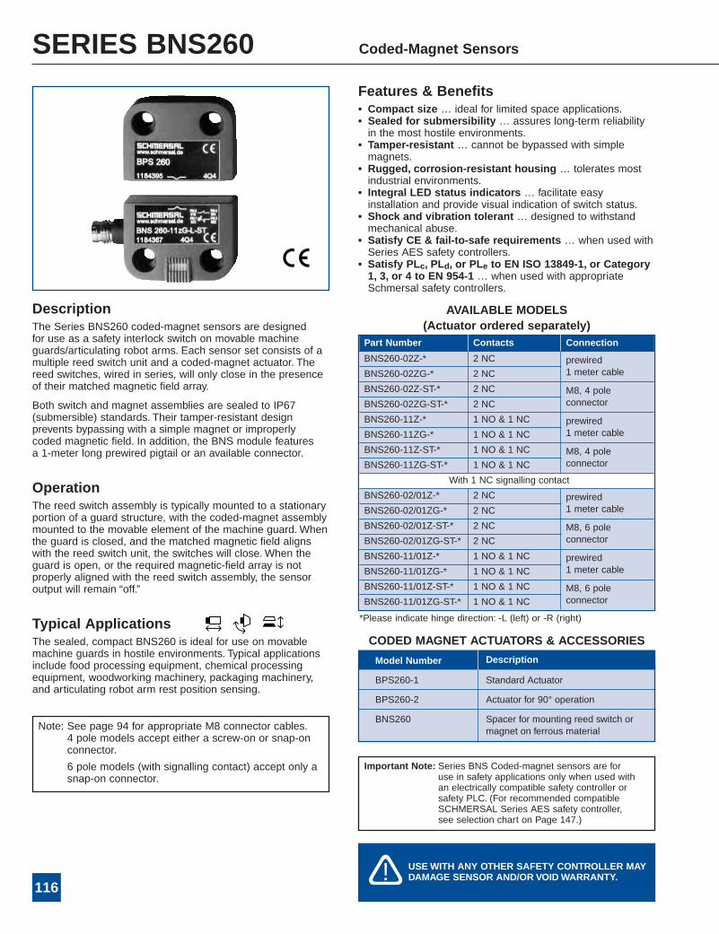
SERIES BNS260 Coded-Magnet Sensors
AVAILABLE MODELS(Actuator ordered separately)
DescriptionThe Series BNS260 coded-magnet sensors are designedfor use as a safety interlock switch on movable machineguards/articulating robot arms. Each sensor set consists of amultiple reed switch unit and a coded-magnet actuator. Thereed switches, wired in series, will only close in the presenceof their matched magnetic field array.
Both switch and magnet assemblies are sealed to IP67(submersible) standards. Their tamper-resistant designprevents bypassing with a simple magnet or improperlycoded magnetic field. In addition, the BNS module featuresa 1-meter long prewired pigtail or an available connector.
OperationThe reed switch assembly is typically mounted to a stationaryportion of a guard structure, with the coded-magnet assemblymounted to the movable element of the machine guard. Whenthe guard is closed, and the matched magnetic field alignswith the reed switch unit, the switches will close. When theguard is open, or the required magnetic-field array is notproperly aligned with the reed switch assembly, the sensoroutput will remain “off.”
Typical ApplicationsThe sealed, compact BNS260 is ideal for use on movablemachine guards in hostile environments. Typical applicationsinclude food processing equipment, chemical processingequipment, woodworking machinery, packaging machinery,and articulating robot arm rest position sensing.
Features & Benefits• Compact size … ideal for limited space applications.• Sealed for submersibility … assures long-term reliabilityin the most hostile environments.
• Tamper-resistant … cannot be bypassed with simplemagnets.
• Rugged, corrosion-resistant housing … tolerates mostindustrial environments.
• Integral LED status indicators … facilitate easyinstallation and provide visual indication of switch status.
• Shock and vibration tolerant … designed to withstandmechanical abuse.
• Satisfy CE & fail-to-safe requirements … when used withSeries AES safety controllers.
• Satisfy PLc, PLd, or PLe to EN ISO 13849-1, or Category1, 3, or 4 to EN 954-1 … when used with appropriateSchmersal safety controllers.
Important Note: Series BNS Coded-magnet sensors are foruse in safety applications only when used withan electrically compatible safety controller orsafety PLC. (For recommended compatibleSCHMERSAL Series AES safety controller,see selection chart on Page 147.)
USEWITH ANY OTHER SAFETY CONTROLLER MAYDAMAGE SENSOR AND/OR VOIDWARRANTY.�!
CODED MAGNET ACTUATORS & ACCESSORIES
BPS260-1
BPS260-2
BNS260
Standard Actuator
Actuator for 90° operation
Spacer for mounting reed switch ormagnet on ferrous material
Model Number Description
Note: See page 94 for appropriate M8 connector cables.4 pole models accept either a screw-on or snap-onconnector.
6 pole models (with signalling contact) accept only asnap-on connector.
Part Number Contacts Connection
BNS260-02Z-* 2 NC prewired1 meter cableBNS260-02ZG-* 2 NC
BNS260-02Z-ST-* 2 NC M8, 4 poleconnectorBNS260-02ZG-ST-* 2 NC
BNS260-11Z-* 1 NO & 1 NC prewired1 meter cableBNS260-11ZG-* 1 NO & 1 NC
BNS260-11Z-ST-* 1 NO & 1 NC M8, 4 poleconnectorBNS260-11ZG-ST-* 1 NO & 1 NC
With 1 NC signalling contact
BNS260-02/01Z-* 2 NC prewired1 meter cableBNS260-02/01ZG-* 2 NC
BNS260-02/01Z-ST-* 2 NC M8, 6 poleconnectorBNS260-02/01ZG-ST-* 2 NC
BNS260-11/01Z-* 1 NO & 1 NC prewired1 meter cableBNS260-11/01ZG-* 1 NO & 1 NC
BNS260-11/01Z-ST-* 1 NO & 1 NC M8, 6 poleconnectorBNS260-11/01ZG-ST-* 1 NO & 1 NC

*Without ferromagnetic material in vicinity of switch or magnet. Theproximity of ferrous material may affect switching distances.
117
BNS260 TECHNICAL DATA
Maximum Operating Voltage 75VDC24VDC for LED versions
Maximum Continuous 400 mA without LEDCurrent Rating 10 mA with LEDMaximum Switching 10va without LED
240mW with LEDType Connection* 1 meter long LiYY4* 0.25mm2
(23AWG) pre-wired pigtail or M84 or 6 pin connector (ST)
Housing Fiberglass reinforced thermoplasticSwitching Distance “S”* “On”: 5mm (0.2")
“Off”: 15mm (0.6")Degree of Protection IP67Operating Temperature –13°F to +158°FOperating Principle MagneticShock Resistance 30g/11msVibration Resistance 10 to 55 Hz, amplitude 1mmConformity to Standards CE EN 954-1
cUL BG-GS-ET-14EN ISO 13849-1
MECHANICAL SPECIFICATIONS ELECTRICAL SPECIFICATIONS
DIMENSIONS
WIRING DETAILS (Contact configuration shown in presence of BPS260 Coded-magnet actuator)
MISALIGNMENT ALLOWANCEQUICK-CONNECT DIAGRAMS
*Longer prewired cables (3M, 5M, or 10M lengths) available onrequest. Please consult factory.
Note: BNS260 reed switch assemblies should be mounted at least 50mm (2") apart.
mm
BNS260
BNS260-02z(G)
BNS260 4-Pole
BNS260 6-Pole
BNS260-02/01z(G) BNS260-11z(G) BNS260-11/01z(G)
BPS260
Contacts shown with gate closed. Color configuration shown for cabled versions, connector color codes may vary.
5

118
SERIES BNS33 Coded-Magnet Sensors
DescriptionThe Series BNS33 coded-magnet sensors are designed foruse as a safety interlock switch on movable machineguards/articulating robot arms. Each sensor set consists of amultiple reed switch unit and a coded-magnet actuator. Thereed switches, wired in series, will only close in the presenceof their matched magnetic field array.
Both switch and magnet assemblies are sealed to IP67(submersible) standards (IP69K for BNS33S). Their tamper-resistant design prevents bypassing with a simple magnet orimproperly coded magnetic field. In addition, the BNS modulefeatures an optional built-in LED display of switch status, anda 1-meter long prewired pigtail to assure sealing integrity.
OperationThe reed switch assembly is typically mounted to a stationaryportion of a guard structure, with the coded-magnet assemblymounted to the movable element of the machine guard. Whenthe guard is closed, and the matched magnetic field alignswith the reed switch unit, the switches will close. When theguard is open, or the required magnetic-field array is notproperly aligned with the reed switch assembly, the sensoroutput will remain “off.”
Typical ApplicationsThe sealed, compact BNS33 is ideal for use on movablemachine guards in hostile environments or where space islimited. Typical applications include food processingequipment, chemical processing equipment, woodworkingmachinery, packaging machinery, and articulating robot armrest position sensing.
Features & Benefits• Compact size … ideal for limited space applications.• Sealed for submersibility … assures long-term reliabilityin the most hostile environments.
• Tamper-resistant … cannot be bypassed with simplemagnets.
• Rugged, corrosion-resistant housing … tolerates mostindustrial environments.
• Integral LED status indicators … facilitate easyinstallations and provide visual indication of switch status.
• Shock and vibration tolerant … designed to withstandmechanical abuse.
• Satisfy PLc, PLd, or PLe to EN ISO 13849-1, orCategory 1, 3, or 4 to EN 954-1 … when used withappropriate Schmersal safety controllers.
• Optional high-strength field coded-magnets …extends sensing range to 10mm.
• Units available with M8 quick-connect.(Please consult factory.)
• Available stainless steel housing (BNS33S) … idealfor the food industry (see page 122).
Required SafetyController.
*Important Note: Series BNS Coded-magnet sensors are foruse in safety applications only when used withan electrically compatible safety controller orsafety PLC. (For recommended compatibleSCHMERSAL Series AES safety controller,see selection chart on Page 147.)
USEWITH ANY OTHER SAFETY CONTROLLER MAYDAMAGE SENSOR AND/OR VOIDWARRANTY.�!
119
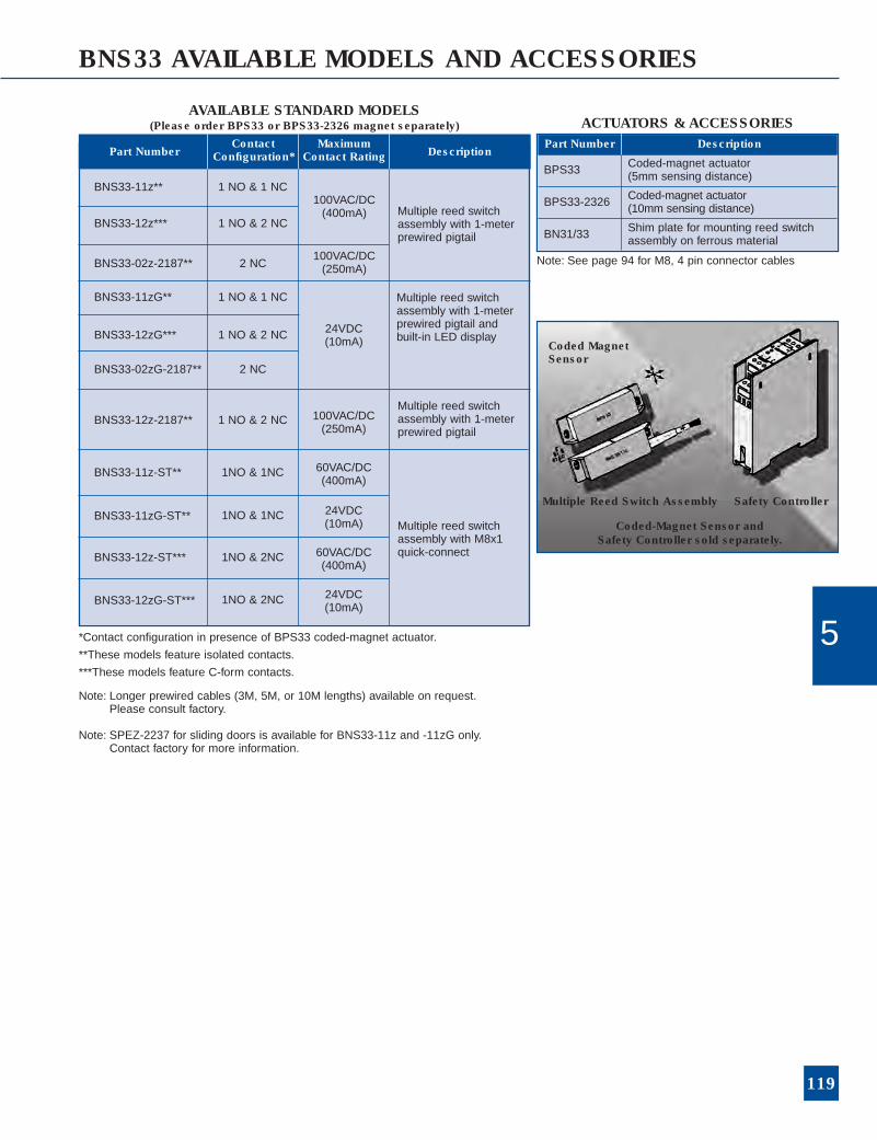
BNS33 AVAILABLE MODELS AND ACCESSORIES
Coded MagnetSensor
Multiple Reed Switch Assembly Safety Controller
Coded-Magnet Sensor andSafety Controller sold separately.
AVAILABLE STANDARD MODELS(Please order BPS33 or BPS33-2326 magnet separately)
BNS33-11z** 1 NO & 1 NC
BNS33-12z*** 1 NO & 2 NC
BNS33-02z-2187** 2 NC
BNS33-11zG** 1 NO & 1 NC
BNS33-12zG*** 1 NO & 2 NC
Multiple reed switchassembly with 1-meterprewired pigtail
Multiple reed switchassembly with 1-meterprewired pigtail andbuilt-in LED display
BNS33-02zG-2187** 2 NC
Part NumberContact
Configuration*Maximum
Contact Rating Description
BNS33-12z-2187** 1 NO & 2 NC
BNS33-11z-ST**
BNS33-11zG-ST**
BNS33-12z-ST***
BNS33-12zG-ST***
1NO & 1NC
1NO & 1NC
1NO & 2NC
1NO & 2NC
100VAC/DC(400mA)
100VAC/DC(250mA)
24VDC(10mA)
100VAC/DC(250mA)
60VAC/DC(400mA)
24VDC(10mA)
60VAC/DC(400mA)
24VDC(10mA)
Multiple reed switchassembly with M8x1quick-connect
Multiple reed switchassembly with 1-meterprewired pigtail
*Contact configuration in presence of BPS33 coded-magnet actuator.
**These models feature isolated contacts.
***These models feature C-form contacts.
Note: Longer prewired cables (3M, 5M, or 10M lengths) available on request.Please consult factory.
Note: See page 94 for M8, 4 pin connector cables
Note: SPEZ-2237 for sliding doors is available for BNS33-11z and -11zG only.Contact factory for more information.
ACTUATORS & ACCESSORIES
5
Part Number Description
BPS33 Coded-magnet actuator(5mm sensing distance)
BPS33-2326 Coded-magnet actuator(10mm sensing distance)
BN31/33 Shim plate for mounting reed switchassembly on ferrous material
*Without ferromagnetic material in vicinity of switch or magnet. Theproximity of ferrous material may affect switching distances.
120
BNS33 TECHNICAL DATA
For electrical ratings see page 139
Type Connection* 1 meter long LiYY4* 0.25mm2
(23AWG) pre-wired pigtail.M8x1 quick-connect for versionswith “ST” suffix
Housing Fiberglass reinforced thermoplasticSwitching Distance “S”* “On”: 5mm (0.2")
“Off”: 15mm (0.6")“On”: 8mm (0.3") (For BNS33S only)“Off”: 18mm (0.7") (For BNS33S only)
Degree of Protection IP67 (BNS33S: IP69k)Operating Temperature –13°F to +158°F (+178°F for BNS33S)Operating Principle MagneticShock Resistance 30g/11msVibration Resistance 10 to 55 Hz, amplitude 1mmConformity to Standards CE EN ISO 13849-1
UL EN 954-1CSA BG-GS-ET-14IEC 529/EN60529
MECHANICAL SPECIFICATIONS ELECTRICAL SPECIFICATIONS
*Longer prewired cables available on request. Please consult factory.
BPS33 MISALIGNMENT ALLOWANCE

121
BNS33 TECHNICAL DATA
DIMENSIONS
WIRING DETAILS
Note: BNS33 reed switch assemblies should be mounted at least 50mm (2") apart.
3,5
0.14
0,5
.02
70.
28
25 0.98
13 0.51
3.0
12
783.07
4,50.18
883.47
M 8
ø5
.02
DIA
18,5
.073
BNS33 with Quick-Connect Terminal
Note: 27mm width and14.5mm depth forBNS33S/BPS33S
Contacts shown with gate closed
5Quick-Connect forBNS33-11 units
Pins 1-2 are Normally-closedPins 3-4 are Normally-open
1 4
2 3
Quick-Connect forBNS33-12 units
Pin 1: CommonPins 2 & 4 are Normally-closedPin 3 is Normally-open
1 4
2 3BNS33-02zG-2187

AVAILABLE STANDARD MODELS(Please order BPS33S magnet separately)
Part NumberContact
Configuration*
MaximumContactRating
Description
BPS33S N/A N/AStainless steelcoded-magnetactuator
BNS33S-12z** 1 NO & 2 NC
BNS33S-12zG** 1 NO & 2 NC
100VAC/DC(250mA)
24VDC(10mA)
Multiple reedswitch assemblywith 1-meterprewired pigtailand stainlesssteel enclosure
*Contact configuration in presence of BPS33S coded-magnet actuator.
**These models feature isolated contacts.
Note: Longer prewired cables (3M, 5M, or 10M lengths) available onrequest. Please consult factory.
122
SERIES BNS33S Stainless Steel Coded-Magnet Sensors
DescriptionThe Series BNS33S coded-magnet sensor is designed foruse as a safety interlock switch on movable machineguards/articulating robot arms. Each sensor set consists of amultiple reed switch unit and a coded-magnet actuator. Thereed switches, wired in series, will only close in the presenceof their matched magnetic field array.
Both switch and magnet assemblies are sealed to IP69Kstandards. Their tamper-resistant design prevents bypassingwith a simple magnet or improperly coded magnetic field. Inaddition, the BNS module features an optional built-in LEDdisplay of switch status, and a 1-meter long prewired pigtail toassure sealing integrity.
OperationThe reed switch assembly is typically mounted to a stationaryportion of a guard structure, with the coded-magnet assemblymounted to the movable element of the machine guard. Whenthe guard is closed, and the matched magnetic field alignswith the reed switch unit, the switches will close. When theguard is open, or the required magnetic-field array is notproperly aligned with the reed switch assembly, the sensoroutput will remain “off.”
Typical ApplicationsThe sealed, compact BNS33S is ideal for use on movablemachine guards in hostile environments or where space islimited. Typical applications include food processingequipment, chemical processing equipment, woodworkingmachinery, packaging machinery, and articulating robot armrest position sensing.
Features & Benefits• Compact size … ideal for limited space applications.• Sealed for submersibility … assures long-term reliabilityin the most hostile environments.
• Tamper-resistant … cannot be bypassed with simplemagnets.
• Rugged, corrosion-resistant housing … tolerates mostindustrial environments.
• Integral LED status indicators … facilitate easyinstallations and provide visual indication of switch status.
• Shock and vibration tolerant … designed to withstandmechanical abuse.
• Satisfy PLc, PLd, or PLe to EN ISO 13849-1, orCategory 1, 3, or 4 to EN 954-1 … when used withappropriate Schmersal safety controllers.
• Stainless steel housing … ideal for the food industry.
*Important Note: Series BNS Coded-magnet sensors are foruse in safety applications only when used withan electrically compatible safety controller orsafety PLC. (For recommended compatibleSCHMERSAL Series AES safety controller,see selection chart on Page 147.)
USEWITH ANY OTHER SAFETY CONTROLLER MAYDAMAGE SENSOR AND/OR VOIDWARRANTY.�!
*Without ferromagnetic material in vicinity of switch or magnet. Theproximity of ferrous material may affect switching distances.
123
BNS33S TECHNICAL DATA
For electrical ratings see page
Type Connection* 1 meter long LiYY4* 0.25mm2
(23AWG) pre-wired pigtail.
Housing Type V4A (316L) stainless steelSwitching Distance “S”* “On”: 8mm (0.3")
“Off”: 18mm (0.7")Degree of Protection IP69kOperating Temperature –13°F to +178°FOperating Principle MagneticShock Resistance 30g/11msVibration Resistance 10 to 55 Hz, amplitude 1mmConformity to Standards CE EN 954-1
IEC 529/EN60529 BG-GS-ET-14EN ISO 13849-1
MECHANICAL SPECIFICATIONS ELECTRICAL SPECIFICATIONS
*Longer prewired cables available on request. Please consult factory.
BNS33S MISALIGNMENT ALLOWANCE
DIMENSIONS
WIRING DETAILS
Note: BNS33 reed switch assemblies should be mounted at least 50mm (2") apart.
BPS33S BNS33S
Contacts shown with gate closed
5
124
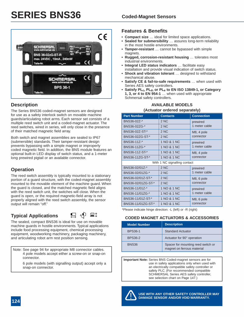
SERIES BNS36 Coded-Magnet Sensors
AVAILABLE MODELS(Actuator ordered separately)
DescriptionThe Series BNS36 coded-magnet sensors are designedfor use as a safety interlock switch on movable machineguards/articulating robot arms. Each sensor set consists of amultiple reed switch unit and a coded-magnet actuator. Thereed switches, wired in series, will only close in the presenceof their matched magnetic field array.
Both switch and magnet assemblies are sealed to IP67(submersible) standards. Their tamper-resistant designprevents bypassing with a simple magnet or improperlycoded magnetic field. In addition, the BNS module features anoptional built-in LED display of switch status, and a 1-meterlong prewired pigtail or an available connector.
OperationThe reed switch assembly is typically mounted to a stationaryportion of a guard structure, with the coded-magnet assemblymounted to the movable element of the machine guard. Whenthe guard is closed, and the matched magnetic field alignswith the reed switch unit, the switches will close. When theguard is open, or the required magnetic-field array is notproperly aligned with the reed switch assembly, the sensoroutput will remain “off.”
Typical ApplicationsThe sealed, compact BNS36 is ideal for use on movablemachine guards in hostile environments. Typical applicationsinclude food processing equipment, chemical processingequipment, woodworking machinery, packaging machinery,and articulating robot arm rest position sensing.
Features & Benefits• Compact size … ideal for limited space applications.• Sealed for submersibility … assures long-term reliabilityin the most hostile environments.
• Tamper-resistant … cannot be bypassed with simplemagnets.
• Rugged, corrosion-resistant housing … tolerates mostindustrial environments.
• Integral LED status indicators … facilitate easyinstallation and provide visual indication of switch status.
• Shock and vibration tolerant … designed to withstandmechanical abuse.
• Satisfy CE & fail-to-safe requirements … when used withSeries AES safety controllers.
• Satisfy PLc, PLd, or PLe to EN ISO 13849-1, or Category1, 3, or 4 to EN 954-1 … when used with appropriateSchmersal safety controllers.
Important Note: Series BNS Coded-magnet sensors are foruse in safety applications only when used withan electrically compatible safety controller orsafety PLC. (For recommended compatibleSCHMERSAL Series AES safety controller,see selection chart on Page 147.)
USEWITH ANY OTHER SAFETY CONTROLLER MAYDAMAGE SENSOR AND/OR VOIDWARRANTY.�!
CODED MAGNET ACTUATORS & ACCESSORIES
BPS36-1
BPS36-2
BNS36
Standard Actuator
Actuator for 90° operation
Spacer for mounting reed switch ormagnet on ferrous material
Model Number Description
Note: See page 94 for appropriate M8 connector cables.4 pole models accept either a screw-on or snap-onconnector.
6 pole models (with signalling output) accept only asnap-on connector.
*Please indicate hinge direction: -L (left) or -R (right)
Part Number Contacts Connection
BNS36-02Z-* 2 NC prewired1 meter cableBNS36-02ZG-* 2 NC
BNS36-02Z-ST-* 2 NC M8, 4 poleconnectorBNS36-02ZG-ST-* 2 NC
BNS36-11Z-* 1 NO & 1 NC prewired1 meter cableBNS36-11ZG-* 1 NO & 1 NC
BNS36-11Z-ST-* 1 NO & 1 NC M8, 4 poleconnectorBNS36-11ZG-ST-* 1 NO & 1 NC
With 1 NC signalling contact
BNS36-02/01Z-* 2 NC prewired1 meter cableBNS36-02/01ZG-* 2 NC
BNS36-02/01Z-ST-* 2 NC M8, 6 poleconnectorBNS36-02/01ZG-ST-* 2 NC
BNS36-11/01Z-* 1 NO & 1 NC prewired1 meter cableBNS36-11/01ZG-* 1 NO & 1 NC
BNS36-11/01Z-ST-* 1 NO & 1 NC M8, 6 poleconnectorBNS36-11/01ZG-ST-* 1 NO & 1 NC

*Without ferromagnetic material in vicinity of switch or magnet. Theproximity of ferrous material may affect switching distances.
125
BNS36 TECHNICAL DATA
Maximum Operating Voltage 75V DC24VDC for LED versions
Maximum Continuous 400 mA without LEDCurrent Rating 10 mA with LEDMaximum Switching 10va without LED
240mW with LEDType Connection* 1 meter long LiYY* 0.25mm2
(23AWG) pre-wired pigtail or M84 or 6 pin connector (ST)
Housing Fiberglass reinforced thermoplasticSwitching Distance “S”* “On”: 7mm
“Off”: 17mmDegree of Protection IP67Operating Temperature –13°F to +158°FOperating Principle MagneticShock Resistance 30g/11msVibration Resistance 10 to 55 Hz, amplitude 1mmConformity to Standards CE EN 954-1
BG-GS-ET14 ULEN ISO 13849-1 CSA
MECHANICAL SPECIFICATIONS ELECTRICAL SPECIFICATIONS
DIMENSIONS
WIRING DETAILS (Contact configuration shown in presence of BPS36 Coded-magnet actuator)
MISALIGNMENT ALLOWANCEQUICK-CONNECT DIAGRAMS
*Longer prewired cables (3M, 5M, or 10M lengths) available onrequest. Please consult factory.
Note: BNS36 reed switch assemblies should be mounted at least 50mm (2") apart.
BNS36 BPS36
BNS36-02z(G)
BNS36 4-Pole
BNS36 6-Pole
BNS36-02/01z(G) BNS36-11z(G) BNS36-11/01z(G)
BNS36 Spacer
Contacts shown with gate closed. Color configuration shown for cabled versions, connector color codes may vary.
5
126
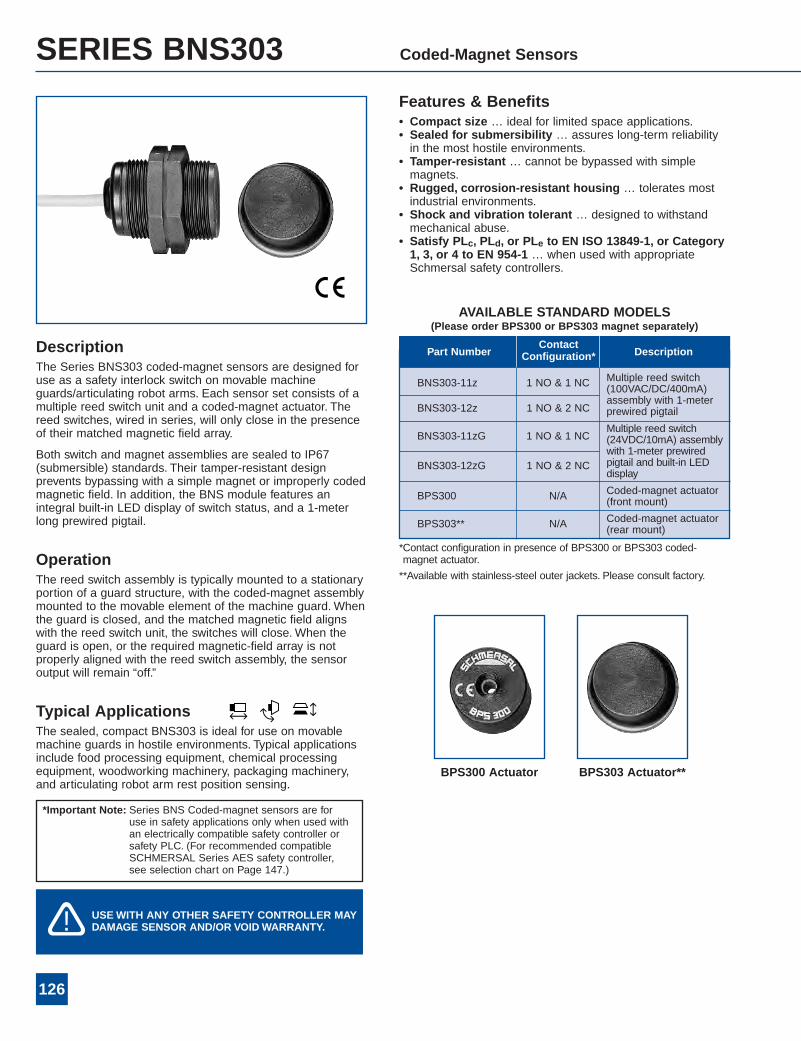
SERIES BNS303 Coded-Magnet Sensors
DescriptionThe Series BNS303 coded-magnet sensors are designed foruse as a safety interlock switch on movable machineguards/articulating robot arms. Each sensor set consists of amultiple reed switch unit and a coded-magnet actuator. Thereed switches, wired in series, will only close in the presenceof their matched magnetic field array.
Both switch and magnet assemblies are sealed to IP67(submersible) standards. Their tamper-resistant designprevents bypassing with a simple magnet or improperly codedmagnetic field. In addition, the BNS module features anintegral built-in LED display of switch status, and a 1-meterlong prewired pigtail.
OperationThe reed switch assembly is typically mounted to a stationaryportion of a guard structure, with the coded-magnet assemblymounted to the movable element of the machine guard. Whenthe guard is closed, and the matched magnetic field alignswith the reed switch unit, the switches will close. When theguard is open, or the required magnetic-field array is notproperly aligned with the reed switch assembly, the sensoroutput will remain “off.”
Typical ApplicationsThe sealed, compact BNS303 is ideal for use on movablemachine guards in hostile environments. Typical applicationsinclude food processing equipment, chemical processingequipment, woodworking machinery, packaging machinery,and articulating robot arm rest position sensing.
Features & Benefits• Compact size … ideal for limited space applications.• Sealed for submersibility … assures long-term reliabilityin the most hostile environments.
• Tamper-resistant … cannot be bypassed with simplemagnets.
• Rugged, corrosion-resistant housing … tolerates mostindustrial environments.
• Shock and vibration tolerant … designed to withstandmechanical abuse.
• Satisfy PLc, PLd, or PLe to EN ISO 13849-1, or Category1, 3, or 4 to EN 954-1 … when used with appropriateSchmersal safety controllers.
AVAILABLE STANDARD MODELS(Please order BPS300 or BPS303 magnet separately)
BNS303-11z 1 NO & 1 NC
BNS303-12z 1 NO & 2 NC
Multiple reed switch(100VAC/DC/400mA)assembly with 1-meterprewired pigtail
BNS303-11zG 1 NO & 1 NC
BNS303-12zG 1 NO & 2 NC
Multiple reed switch(24VDC/10mA) assemblywith 1-meter prewiredpigtail and built-in LEDdisplay
Coded-magnet actuator(front mount)
Part NumberContact
Configuration* Description
BPS300 N/A
Coded-magnet actuator(rear mount)BPS303** N/A
*Contact configuration in presence of BPS300 or BPS303 coded-magnet actuator.
**Available with stainless-steel outer jackets. Please consult factory.
BPS300 Actuator BPS303 Actuator**
*Important Note: Series BNS Coded-magnet sensors are foruse in safety applications only when used withan electrically compatible safety controller orsafety PLC. (For recommended compatibleSCHMERSAL Series AES safety controller,see selection chart on Page 147.)
USEWITH ANY OTHER SAFETY CONTROLLER MAYDAMAGE SENSOR AND/OR VOIDWARRANTY.�!
127
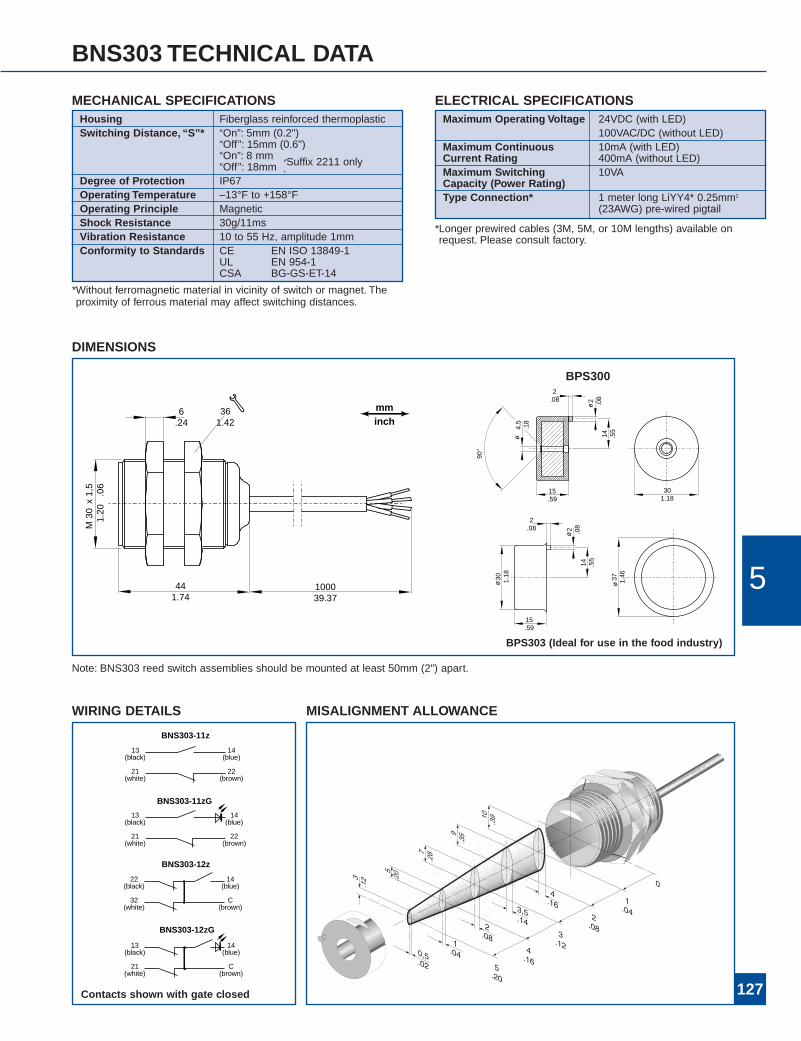
BNS303 TECHNICAL DATA
Maximum Operating Voltage 24VDC (with LED)100VAC/DC (without LED)
Maximum Continuous 10mA (with LED)Current Rating 400mA (without LED)Maximum Switching 10VACapacity (Power Rating)Type Connection* 1 meter long LiYY4* 0.25mm2
(23AWG) pre-wired pigtail
Housing Fiberglass reinforced thermoplasticSwitching Distance, “S”* “On”: 5mm (0.2")
“Off”: 15mm (0.6")“On”: 8 mm“Off”: 18mm
Degree of Protection IP67Operating Temperature –13°F to +158°FOperating Principle MagneticShock Resistance 30g/11msVibration Resistance 10 to 55 Hz, amplitude 1mmConformity to Standards CE EN ISO 13849-1
UL EN 954-1CSA BG-GS-ET-14
MECHANICAL SPECIFICATIONS ELECTRICAL SPECIFICATIONS
BNS303-12z
22(black)
32(white)
14(blue)
C(brown)
BNS303-11z
13(black)
21(white)
14(blue)
22(brown)
BNS303-12zG
13(black)
21(white)
14(blue)
C(brown)
22(brown)
21(white)
BNS303-11zG
13(black)
14(blue)
WIRING DETAILS
*Longer prewired cables (3M, 5M, or 10M lengths) available onrequest. Please consult factory.
¸˝Suffix 2211 only˛
*Without ferromagnetic material in vicinity of switch or magnet. Theproximity of ferrous material may affect switching distances.
Note: BNS303 reed switch assemblies should be mounted at least 50mm (2") apart.
MISALIGNMENT ALLOWANCE
DIMENSIONS
441.74
M30 1.20
x1,
5.0
6
100039.37
6.24
361.42
2.08
30 1.18
15.59
90°
14 .55
ø2 .08
ø4,
5.1
8
15.59
2.08
14 .55
ø2 .08
ø37 1.46
ø30 1.18
BPS303 (Ideal for use in the food industry)
mminch
Contacts shown with gate closed
5
BPS300
128
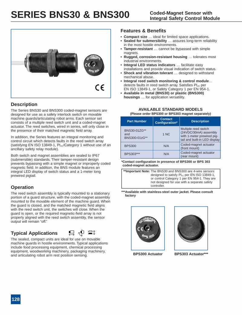
SERIES BNS30 & BNS300 Coded-Magnet Sensor withIntegral Safety Control Module
AVAILABLE STANDARD MODELS(Please order BPS300 or BPS303 magnet separately)
DescriptionThe Series BNS30 and BNS300 coded-magnet sensors aredesigned for use as a safety interlock switch on movablemachine guards/articulating robot arms. Each sensor setconsists of a multiple reed switch unit and a coded-magnetactuator. The reed switches, wired in series, will only close inthe presence of their matched magnetic field array.
In addition, the Series features an integral monitoring andcontrol circuit which detects faults in the reed switch array(satisfying EN ISO 13849-1, PLc/Category 1 without use of anancillary safety relay module).
Both switch and magnet assemblies are sealed to IP67(submersible) standards. Their tamper-resistant designprevents bypassing with a simple magnet or improperly codedmagnetic field. In addition, the BNS module features anintegral LED display of switch status and a 1-meter longprewired pigtail.
OperationThe reed switch assembly is typically mounted to a stationaryportion of a guard structure, with the coded-magnet assemblymounted to the movable element of the machine guard. Whenthe guard is closed, and the matched magnetic field alignswith the reed switch unit, the switches will close. When theguard is open, or the required magnetic-field array is notproperly aligned with the reed switch assembly, the sensoroutput will remain “off.”
Typical ApplicationsThe sealed, compact units are ideal for use on movablemachine guards in hostile environments. Typical applicationsinclude food processing equipment, chemical processingequipment, woodworking machinery, packaging machinery,and articulating robot arm rest position sensing.
BNS30-01ZG**andBNS300-01zG**
1 NC
BPS300 N/A
Multiple reed switch(24VDC/30mA) assemblywith 1-meter prewired pig-tail and built-in LED display
Coded-magnet actuator(front mount)
BPS303*** N/A Coded-magnet actuator(rear mount)
Part NumberContact
Configuration* Description
Features & Benefits• Compact size … ideal for limited space applications.• Sealed for submersibility … assures long-term reliabilityin the most hostile environments.
• Tamper-resistant … cannot be bypassed with simplemagnets.
• Rugged, corrosion-resistant housing … tolerates mostindustrial environments.
• Integral LED status indicators … facilitate easyinstallations and provide visual indication of switch status.
• Shock and vibration tolerant … designed to withstandmechanical abuse.
• Integral reed switch monitoring & control module…detects faults in reed switch array. Satisfies PLc perEN ISO 13849-1, or Safety Category 1 per EN 954-1.
• Available in metal (BNS30) or plastic (BNS300)housings … for application versatility.
*Contact configuration in presence of BPS300 or BPS 303coded-magnet actuator.
***Available with stainless-steel outer jacket. Please consultfactory
**Important Note: The BNS30 and BNS300 are 4-wire sensorsdesigned to satisfy PLc per EN ISO 13849-1,or control Category 1 per EN 954-1. They arenot designed for use with a separate safetycontroller.
BPS300 Actuator BPS303 Actuator***
129
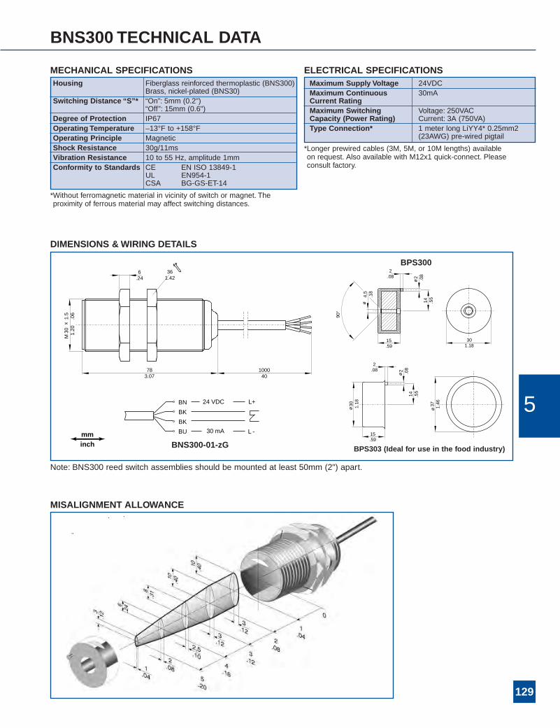
BNS300 TECHNICAL DATA
Maximum Supply Voltage 24VDCMaximum Continuous 30mACurrent RatingMaximum Switching Voltage: 250VACCapacity (Power Rating) Current: 3A (750VA)Type Connection* 1 meter long LiYY4* 0.25mm2
(23AWG) pre-wired pigtail
Housing Fiberglass reinforced thermoplastic (BNS300)Brass, nickel-plated (BNS30)
Switching Distance “S”* “On”: 5mm (0.2")“Off”: 15mm (0.6")
Degree of Protection IP67Operating Temperature –13°F to +158°FOperating Principle MagneticShock Resistance 30g/11msVibration Resistance 10 to 55 Hz, amplitude 1mmConformity to Standards CE EN ISO 13849-1
UL EN954-1CSA BG-GS-ET-14
MECHANICAL SPECIFICATIONS ELECTRICAL SPECIFICATIONS
*Longer prewired cables (3M, 5M, or 10M lengths) availableon request. Also available with M12x1 quick-connect. Pleaseconsult factory.
*Without ferromagnetic material in vicinity of switch or magnet. Theproximity of ferrous material may affect switching distances.
Note: BNS300 reed switch assemblies should be mounted at least 50mm (2") apart.
MISALIGNMENT ALLOWANCE
DIMENSIONS &WIRING DETAILS
1000 40
M30 1.20
x1.
5.0
6
6.24
783.07
361.42
2.08
301.18
15.59
90°
14 .55
ø2 .08
ø4,
5.1
8
15.59
2.08
14 .55
ø2 .08
ø37 1.46
ø30 1.18
BNS300-01-zG
BN
BK
BK
BU
24 VDC
30 mA
L+
L -mminch
5
BPS303 (Ideal for use in the food industry)
BPS300
130
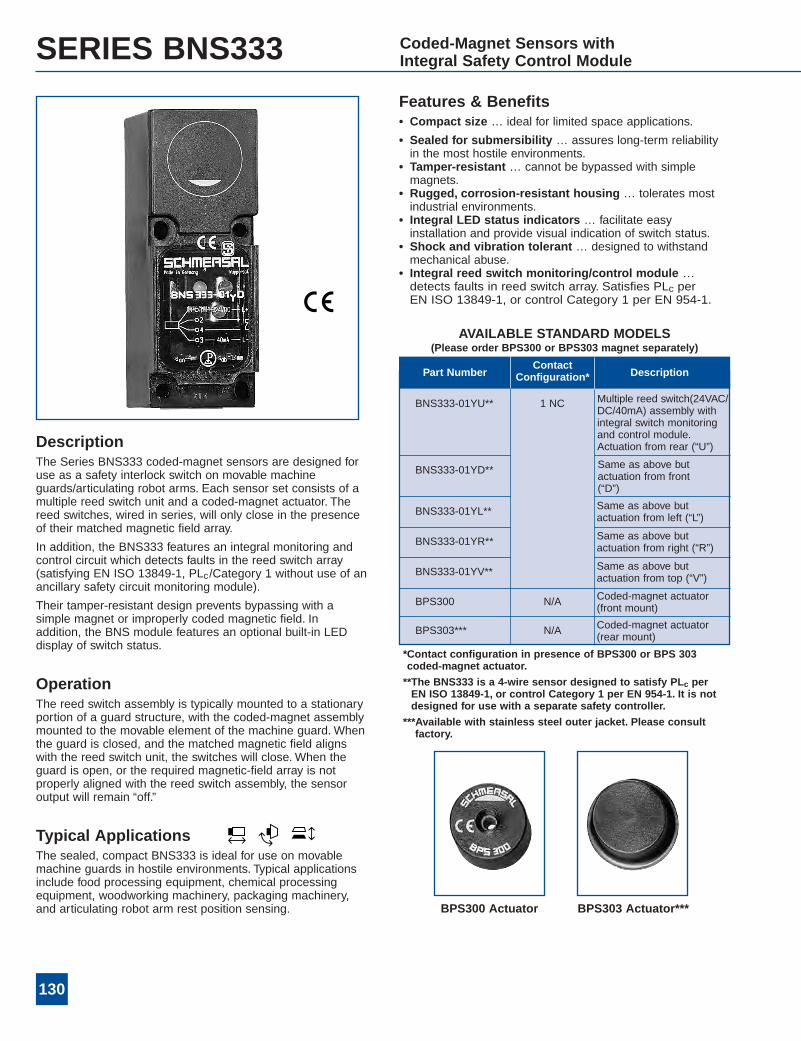
SERIES BNS333 Coded-Magnet Sensors withIntegral Safety Control Module
AVAILABLE STANDARD MODELS(Please order BPS300 or BPS303 magnet separately)
DescriptionThe Series BNS333 coded-magnet sensors are designed foruse as a safety interlock switch on movable machineguards/articulating robot arms. Each sensor set consists of amultiple reed switch unit and a coded-magnet actuator. Thereed switches, wired in series, will only close in the presenceof their matched magnetic field array.
In addition, the BNS333 features an integral monitoring andcontrol circuit which detects faults in the reed switch array(satisfying EN ISO 13849-1, PLc/Category 1 without use of anancillary safety circuit monitoring module).
Their tamper-resistant design prevents bypassing with asimple magnet or improperly coded magnetic field. Inaddition, the BNS module features an optional built-in LEDdisplay of switch status.
OperationThe reed switch assembly is typically mounted to a stationaryportion of a guard structure, with the coded-magnet assemblymounted to the movable element of the machine guard. Whenthe guard is closed, and the matched magnetic field alignswith the reed switch unit, the switches will close. When theguard is open, or the required magnetic-field array is notproperly aligned with the reed switch assembly, the sensoroutput will remain “off.”
Typical ApplicationsThe sealed, compact BNS333 is ideal for use on movablemachine guards in hostile environments. Typical applicationsinclude food processing equipment, chemical processingequipment, woodworking machinery, packaging machinery,and articulating robot arm rest position sensing.
BNS333-01YU** 1 NC
N/A
Multiple reed switch(24VAC/DC/40mA) assembly withintegral switch monitoringand control module.Actuation from rear (“U”)
BNS333-01YD** Same as above butactuation from front(“D”)
BNS333-01YL** Same as above butactuation from left (“L”)
BNS333-01YR** Same as above butactuation from right (“R”)
BNS333-01YV** Same as above butactuation from top (“V”)
BPS300 Coded-magnet actuator(front mount)
N/ABPS303*** Coded-magnet actuator(rear mount)
Part NumberContact
Configuration* Description
Features & Benefits• Compact size … ideal for limited space applications.
• Sealed for submersibility … assures long-term reliabilityin the most hostile environments.
• Tamper-resistant … cannot be bypassed with simplemagnets.
• Rugged, corrosion-resistant housing … tolerates mostindustrial environments.
• Integral LED status indicators … facilitate easyinstallation and provide visual indication of switch status.
• Shock and vibration tolerant … designed to withstandmechanical abuse.
• Integral reed switch monitoring/control module …detects faults in reed switch array. Satisfies PLc perEN ISO 13849-1, or control Category 1 per EN 954-1.
*Contact configuration in presence of BPS300 or BPS 303coded-magnet actuator.
**The BNS333 is a 4-wire sensor designed to satisfy PLc perEN ISO 13849-1, or control Category 1 per EN 954-1. It is notdesigned for use with a separate safety controller.
***Available with stainless steel outer jacket. Please consultfactory.
BPS300 Actuator BPS303 Actuator***

131
BNS333 TECHNICAL DATA
Housing Fiberglass reinforced thermoplasticSwitching Distance “S”* “On”: 4mm (0.16")
“Off”: 14mm (0.55")Degree of Protection IP65Operating Temperature –13°F to +158°FOperating Principle MagneticShock Resistance 30g/11msVibration Resistance 10 to 55 Hz, amplitude 1mmConformity to Standards CE
EN ISO 13849-1EN 954-1BG-GS-ET-14
MECHANICAL SPECIFICATIONSMaximum Operating Voltage 24VDCMaximum Continuous 40mACurrent RatingMaximum Switching Voltage: 250VACCapacity (Power Rating) Current: 5A
(1,250VA)Type Connection Screw terminals
ELECTRICAL SPECIFICATIONS
*Without ferromagnetic material in vicinity of switch or magnet. Theproximity of ferrous material may affect switching distances.
DIMENSIONS &WIRING DETAILS
401.57
401.57
301.18
45 1.77
60 2.36
7,3
.29
5,3
.49
112
4.40
34,31.35
M20
2.08
301.18
15 .59
90°
14 .55
ø2 .08
ø4,
5.1
8
15.59
2.08
14 .55
ø2 .08
ø37 1.46
ø30 1.18
BPS 303 (Ideal for use in the food industry)
BNS333-01y
BPS300
24 VDC
40 mA
1234
L+
L-
MISALIGNMENT ALLOWANCE
Actuating directions
mminch
5
132
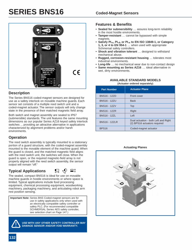
SERIES BNS16 Coded-Magnet Sensors
DescriptionThe Series BNS16 coded-magnet sensors are designed foruse as a safety interlock on movable machine guards. Eachsensor set consists of a multiple reed switch unit and acoded-magnet actuator. The sensor outputs will only changestate in the presence of their matched magnetic field array.
Both switch and magnet assembly are sealed to IP67(submersible) standards. The unit features the same mountingdimensions as our popular Series AZ16 keyed safety interlockswitches ... providing an attractive alternative in applicationscharacterized by alignment problems and/or harshenvironments.
OperationThe reed switch assembly is typically mounted to a stationaryportion of a guard structure, with the coded-magnet assemblymounted to the movable element of the machine guard. Whenthe guard is closed, and the matched magnetic field alignswith the reed switch unit, the switches will close. When theguard is open, or the required magnetic-field array is notproperly aligned with the reed switch assembly, the sensoroutput will remain “off.”
Typical ApplicationsThe sealed, compact BNS16 is ideal for use on movablemachine guards in hostile environments or where space islimited. Typical applications include food processingequipment, chemical processing equipment, woodworkingmachinery, packaging machinery, and articulating robot armrest position sensing.
BNS16 - 12ZD
BNS16 - 12ZU
BNS16 - 12ZV
BNS16 - 12ZR
Dual actuation - both Left and Right(2) BPS16 actuators required
Back
Top
Right
Left
Front cover
BNS16 - 12ZL
BNS16 - 12ZLR
Coded-magnet actuatorBPS16
Part Number Actuator Plane
Features & Benefits• Sealed for submersibility … assures long-term reliabilityin the most hostile environments.
• Tamper-resistant … cannot be bypassed with simplemagnets.
• Satisfy PLc, PLd, or PLe to EN ISO 13849-1, or Category1, 3, or 4 to EN 954-1 … when used with appropriateSchmersal safety controllers.
• Shock and vibration tolerant … designed to withstandmechanical abuse.
• Rugged, corrosion-resistant housing … tolerates mostindustrial environments.
• Long-life … no mechanical wear due to non-contact design• Same mounting as Series AZ16 … ideal alternative inwet, dirty environments.
Actuating Planes
Important Note: Series BNS Coded-magnet sensors are foruse in safety applications only when used withan electrically compatible safety controller orsafety PLC. (For recommended compatibleSCHMERSAL Series AES safety controller,see selection chart on Page 147.)
USEWITH ANY OTHER SAFETY CONTROLLER MAYDAMAGE SENSOR AND/OR VOIDWARRANTY.�!
AVAILABLE STANDARD MODELS(Actuator ordered separately)
*When no ferromagnetic material is present in vicinity of the sensoror actuator.
133
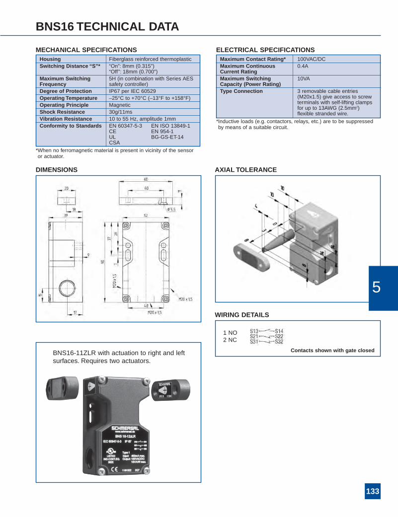
BNS16 TECHNICAL DATA
Housing Fiberglass reinforced thermoplasticSwitching Distance “S”* “On”: 8mm (0.315")
“Off”: 18mm (0.700")Maximum Switching 5H (in combination with Series AESFrequency safety controller)Degree of Protection IP67 per IEC 60529Operating Temperature –25°C to +70°C (–13°F to +158°F)Operating Principle MagneticShock Resistance 30g/11msVibration Resistance 10 to 55 Hz, amplitude 1mmConformity to Standards EN 60347-5-3 EN ISO 13849-1
CE EN 954-1UL BG-GS-ET-14CSA
MECHANICAL SPECIFICATIONSMaximum Contact Rating* 100VAC/DCMaximum Continuous 0.4ACurrent RatingMaximum Switching 10VACapacity (Power Rating)Type Connection 3 removable cable entries
(M20x1.5) give access to screwterminals with self-lifting clampsfor up to 13AWG (2.5mm2)flexible stranded wire.
ELECTRICAL SPECIFICATIONS
*Inductive loads (e.g. contactors, relays, etc.) are to be suppressedby means of a suitable circuit.
AXIAL TOLERANCEDIMENSIONS
BNS16-11ZLR with actuation to right and leftsurfaces. Requires two actuators.
WIRING DETAILS
1 NO2 NC
Contacts shown with gate closed
5
136
Features & Benefits• Tamper-resistant … cannot be bypassed with simplemagnets
• Sealed for submersibility … assures long-term reliabilityin the most hostile environments.
• Dual-function latch & sensor … integral magnetic holdinglatch (with force of 100N).
• Application flexibility … 3-contact design compatible with35mm, 40mm, and 45mm aluminum profiles
• Long-life … no mechanical wear due to non-contactdesign.
• Satisfy PLc, PLd, or PLe to EN ISO 13849-1, or Category1, 3, or 4 to EN 954-1 … when used with appropriateSchmersal safety controllers.
• Easy-to-install … optional M12 x 1 quick disconnect &LED status indicator in NC circuit
• Application diversity … suitable for hinged & slidingguards, available for left- or right-hand doors/guards.
• Integral LED … displays switch status (non-LED modelsalso available).
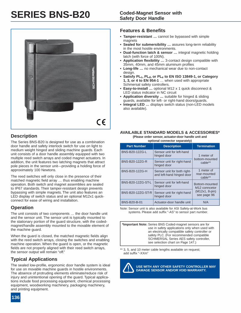
DescriptionThe Series BNS-B20 is designed for use as a combinationdoor handle and safety interlock switch for use on light tomedium weight hinged and sliding machine guards. Eachunit consists of a door handle assembly equipped with twomultiple reed switch arrays and coded magnet actuators. Inaddition, the unit features two latching magnets that attractpole pieces in the sensor unit—providing a holding force ofapproximately 100 Newtons.
The reed switches will only close in the presence of theirmatched magnetic field array … thus enabling machineoperation. Both switch and magnet assemblies are sealedto IP67 standards. Their tamper-resistant design preventsbypassing with simple magnets. The unit also features anLED display of switch status and an optional M12x1 quick-connect for ease of wiring and installation.
OperationThe unit consists of two components … the door handle unitand the sensor unit. The sensor unit is typically mounted tothe stationary portion of the guard structure, with the coded-magnet/handle assembly mounted to the movable element ofthe machine guard.
When the guard is closed, the matched magnetic fields alignwith the reed switch arrays, closing the switches and enablingmachine operation. When the guard is open, or the magneticfields are not properly aligned with their reed switch arrays,the sensor output will remain “off.”
Typical ApplicationsThe sealed low-profile, ergonomic door handle system is idealfor use on movable machine guards in hostile environments.The absence of protruding elements eliminate/reduce risk ofinjury and unintentional opening of the guard. Typical applica-tions include food processing equipment, chemical processingequipment, woodworking machinery, packaging machinery,and printing equipment.
Note: Sensor unit is also available for ASI Safety-at-Work bussystems. Please add suffix “-AS” to sensor part number.
** 3, 5, and 10 meter cable lengths available on request;add suffix “-XXm”
SERIES BNS-B20 Coded-Magnet Sensor withSafety Door Handle
BNS-B20-12ZG-L Sensor unit for left-handhinged door
BNS-B20-12ZG-R Sensor unit for right-handhinged door
Sensor unit for both right-and left-hand hinged door
1 meter ofbottom-mounted
cable**
Sensor unit for left-handhinged door
Bottom-mountedM12 conncetor(M12x1, 8-pin)see page 96
BNS-B20-12ZG-H 1 meter ofrear-mountedcable**
N/A
BNS-B20-12ZG-ST-L
Sensor unit for right-handhinged door
Actuator-door handle unit
BNS-B20-12ZG-ST-R
BNS-B20-B-01
Part Number Description Termination
*Important Note: Series BNS Coded-magnet sensors are foruse in safety applications only when used withan electrically compatible safety controller orsafety PLC. (For recommended compatibleSCHMERSAL Series AES safety controller,see selection chart on Page 147.)
USEWITH ANY OTHER SAFETY CONTROLLER MAYDAMAGE SENSOR AND/OR VOIDWARRANTY.�!
AVAILABLE STANDARD MODELS & ACCESSORIES*(Please order sensor, actuator-door handle unit and
optional connector separately)
137
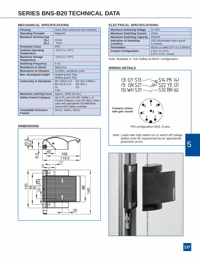
SERIES BNS-B20 TECHNICAL DATA
Housing Glass fiber reinforced thermoplasticOperating Principle MagneticMaximum Sensing Gap
(Sar) 22mm(Sao) 0mm
Protection Class IP67Ambient Operating –25°C to +70°CTemperatureMaximum Storage –25°C to +70°CTemperatureSwitching Frequency 5 HzResistance to Shock 30g/11msResistance to Vibration 10-55Hz, amplitude 1mmMax. door/guard weight Hinged guard: 5Kg
Sliding guard: 3KgConformity to Standards IEC 60947-5-3 EN ISO 13849-1
BG-GS-ET-14 EN 954-1UL CECSA
Maximum Latching Force Approx. 100N (22 lbs.)Safety Control Category Up to PLe per EN ISO 13849-1, or
Control Category 4 per EN 954-1 whenused with appropriate SCHMERSALSeries AES safety controller
Compatible Extrusion 35mm, 40mm, 45mmFrames
MECHANICAL SPECIFICATIONS ELECTRICAL SPECIFICATIONSMaximum Switching Voltage 24 VDCMaximum Switching Current 10mAMaximum Switching Capacity 240mWIndication of Switching LED (Illuminated when guardCondition is closed)Termination M12x1 or cable (LiYY 6 x 0.25mm2)Contact Configuration 1 N.O. & 2 N.C.
(LED in N.C. circuit)
DIMENSIONS
WIRING DETAILS
Note: Available in “ASI Safety-at-Work” configuration.
PIN configuration M12, 8 pins
Note: Loads with high switch-on or switch-off voltagespikes must be suppressed by an appropriateprotective circuit.
Contacts shownwith gate closed
5
138
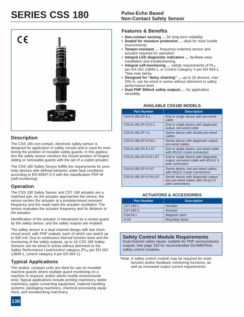
SERIES CSS 180 Pulse-Echo BasedNon-Contact Safety Sensor
Features & Benefits• Non-contact sensing … for long term reliability.• Sealed for moisture protection … ideal for most hostileenvironments.
• Tamper-resistant … frequency-matched sensor andactuator required for operation.
• Integral LED diagnostic indicators … facilitate easyinstallation and troubleshooting.
• Integral self-monitoring … satisfy requirements of PLeper EN ISO 13849-1, or Control Category 4 per EN 954-1.*See note below.
• Designed for “daisy chaining”… up to 16 devices, max200 m, can be wired in series without detriment to safetyperformance level.
• Dual PNP 500mA safety outputs … for applicationversatility.
DescriptionThe CSS 180 non-contact, electronic safety sensor isdesigned for application in safety circuits and is used for mon-itoring the position of movable safety guards. In this applica-tion the safety sensor monitors the closed position of hinged,sliding or removable guards with the aid of a coded actuator.
The CSS 180 Safety Sensor fulfills the requirements for prox-imity devices with defined behavior under fault conditionsaccording to EN 60947-5-3 with the classification PDF-M(self-monitoring).
OperationThe CSS 180 Safety Sensor and CST 180 actuator are amatched pair. As the actuator approaches the sensor, thesensor excites the actuator at a predetermined resonantfrequency and the reads back the actuator oscillation. Thesensor evaluates the actuator frequency and its distance tothe actuator.
Identification of the actuator is interpreted as a closed guardby the safety sensor, and the safety outputs are enabled.
The safety sensor is a dual channel design with two short-circuit proof, safe PNP outputs, each of which can switch upto 500 mA. Due to continuous internal function tests and themonitoring of the safety outputs, up to 16 CSS 180 SafetySensors can be wired in series without detriment to theSafety Performance Level/control category (PLe per EN ISO13849-1, control category 4 per EN 954-1).
Typical ApplicationsThe sealed, compact units are ideal for use on movablemachine guards where multiple guard monitoring on amachine is required, and/or where hostile environmentsexist. Typical applications include printing machinery, textilemachinery, paper converting equipment, material handlingsystems, packaging machinery, chemical processing equip-ment, and woodworking machinery.
Safety Control Module RequirementsDual-channel safety inputs, suitable for PNP semiconductoroutputs. See page 320 for recommended SCHMERSALsafety control modules.
*Note: A safety control module may be required for resetfunction and/or feedback monitoring functions, aswell as increased output current requirements.
AVAILABLE CSS180 MODELSPart Number Description
CSS-8-180-2P-E-L End or single device with pre-wiredcable
CSS-8-180-2P+D-E-L End or single device with diagnosticoutput, pre-wired cable
CSS-8-180-2P-Y-L Series device with double pre-wiredcables
CSS-8-180-2P+D-M-L Series device with diagnostic output,pre-wired cables
CSS-8-180-2P-E-LST End or single device, pre-wired cablewith M12x1 4 pole connection
CSS-8-180-2P+D-E-LST End or single device with diagnosticoutput, pre-wired cable with M12x1 5pole connection
CSS-8-180-2P-Y-LST Series device, two pre-wired cableswith M12x1 4 pole connections
CSS-8-180-2P+D-M-LST Series device with diagnostic output,two pre-wired cables with M12x1 8pole connections
ACTUATORS & ACCESSORIESPart Number Description
CST-180-1 ActuatorCST-180-2 ActuatorCSA-M-1 Magnetic latchH-18 Mounting clamp
139
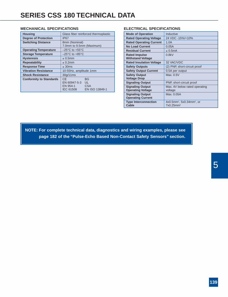
SERIES CSS 180 TECHNICAL DATA
NOTE: For complete technical data, diagnostics and wiring examples, please see
page 182 of the “Pulse-Echo Based Non-Contact Safety Sensors” section.
5
ELECTRICAL SPECIFICATIONSMode of Operation InductiveRated Operating Voltage 24 VDC -15%/+10%Rated Operating Current 1.0ANo Load Current 0.05AResidual Current ≤ 0.5mARated Impulse 0.8kVWithstand VoltageRated Insulation Voltage 32 VAC/VDCSafety Outputs (2) PNP, short-circuit proofSafety Output Current 0.5A per outputSafety Output Max. 0.5VVoltage DropSignaling Output PNP, short-circuit proofSignaling Output Max. 4V below rated operatingOperating Voltage voltageSignaling Output Max. 0.05AOperating CurrentType Interconnection 4x0.5mm2, 5x0.34mm2, orCable 7x0.25mm2
Housing Glass fiber reinforced thermoplasticDegree of Protection IP67Switching Distance 8mm (Nominal)
7.0mm to 9.5mm (Maximum)Operating Temperature –25°C to +55°CStorage Temperature –25°C to +85°CHysteresis ≤ 0.5mmRepeatability ≤ 0.2mmResponse Time ≤ 30msVibration Resistance 10-55Hz, amplitude 1mmShock Resistance 30g/11msConformity to Standards CE BG
EN 60947-5-3 ULEN 954-1 CSAIEC 61508 EN ISO 13849-1
MECHANICAL SPECIFICATIONS
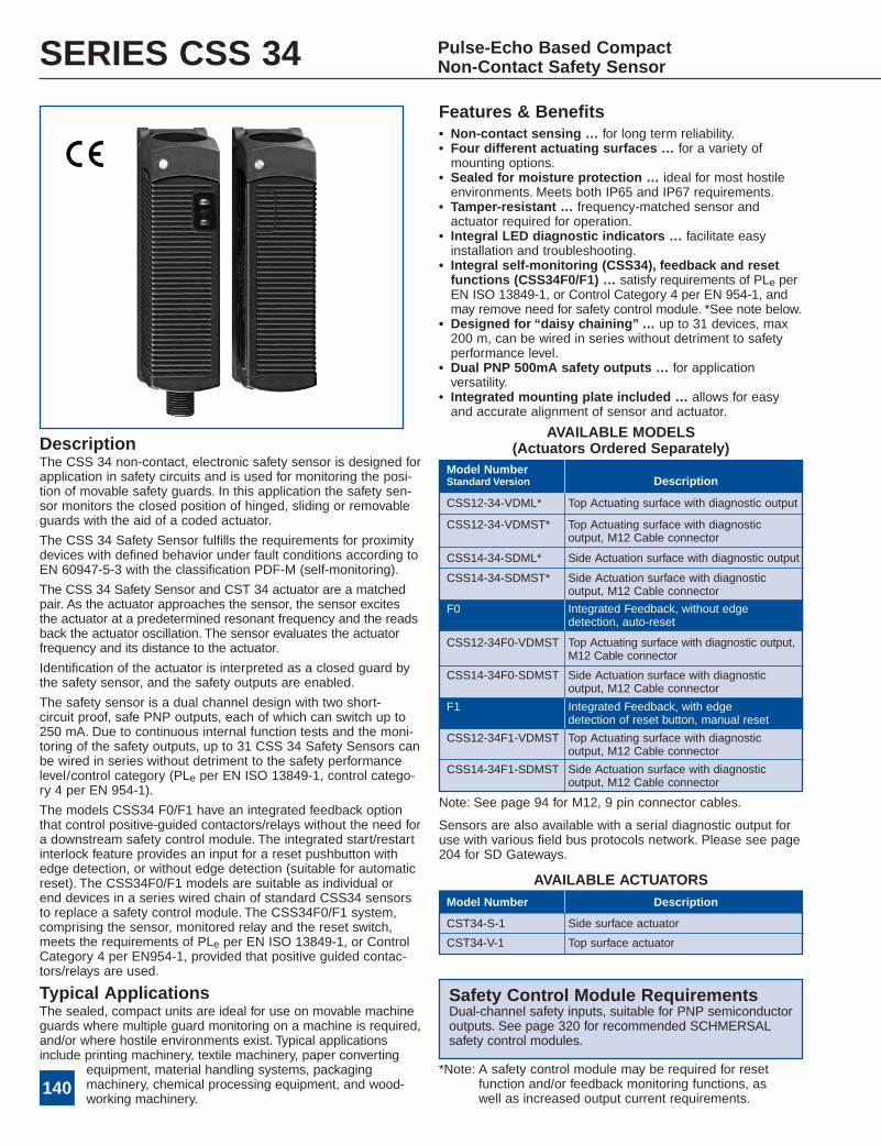
SERIES CSS 34 Pulse-Echo Based CompactNon-Contact Safety Sensor
Features & Benefits• Non-contact sensing … for long term reliability.• Four different actuating surfaces … for a variety ofmounting options.
• Sealed for moisture protection … ideal for most hostileenvironments. Meets both IP65 and IP67 requirements.
• Tamper-resistant … frequency-matched sensor andactuator required for operation.
• Integral LED diagnostic indicators … facilitate easyinstallation and troubleshooting.
• Integral self-monitoring (CSS34), feedback and resetfunctions (CSS34F0/F1) … satisfy requirements of PLe perEN ISO 13849-1, or Control Category 4 per EN 954-1, andmay remove need for safety control module. *See note below.
• Designed for “daisy chaining”… up to 31 devices, max200 m, can be wired in series without detriment to safetyperformance level.
• Dual PNP 500mA safety outputs … for applicationversatility.
• Integrated mounting plate included … allows for easyand accurate alignment of sensor and actuator.
DescriptionThe CSS 34 non-contact, electronic safety sensor is designed forapplication in safety circuits and is used for monitoring the posi-tion of movable safety guards. In this application the safety sen-sor monitors the closed position of hinged, sliding or removableguards with the aid of a coded actuator.
The CSS 34 Safety Sensor fulfills the requirements for proximitydevices with defined behavior under fault conditions according toEN 60947-5-3 with the classification PDF-M (self-monitoring).
The CSS 34 Safety Sensor and CST 34 actuator are a matchedpair. As the actuator approaches the sensor, the sensor excitesthe actuator at a predetermined resonant frequency and the readsback the actuator oscillation. The sensor evaluates the actuatorfrequency and its distance to the actuator.
Identification of the actuator is interpreted as a closed guard bythe safety sensor, and the safety outputs are enabled.
The safety sensor is a dual channel design with two short-circuit proof, safe PNP outputs, each of which can switch up to250 mA. Due to continuous internal function tests and the moni-toring of the safety outputs, up to 31 CSS 34 Safety Sensors canbe wired in series without detriment to the safety performancelevel/control category (PLe per EN ISO 13849-1, control catego-ry 4 per EN 954-1).
The models CSS34 F0/F1 have an integrated feedback optionthat control positive-guided contactors/relays without the need fora downstream safety control module. The integrated start/restartinterlock feature provides an input for a reset pushbutton withedge detection, or without edge detection (suitable for automaticreset). The CSS34F0/F1 models are suitable as individual orend devices in a series wired chain of standard CSS34 sensorsto replace a safety control module. The CSS34F0/F1 system,comprising the sensor, monitored relay and the reset switch,meets the requirements of PLe per EN ISO 13849-1, or ControlCategory 4 per EN954-1, provided that positive guided contac-tors/relays are used.
Typical ApplicationsThe sealed, compact units are ideal for use on movable machineguards where multiple guard monitoring on a machine is required,and/or where hostile environments exist. Typical applicationsinclude printing machinery, textile machinery, paper converting
equipment, material handling systems, packagingmachinery, chemical processing equipment, and wood-working machinery.
Safety Control Module RequirementsDual-channel safety inputs, suitable for PNP semiconductoroutputs. See page 320 for recommended SCHMERSALsafety control modules.
*Note: A safety control module may be required for resetfunction and/or feedback monitoring functions, aswell as increased output current requirements.
Note: See page 94 for M12, 9 pin connector cables.
Sensors are also available with a serial diagnostic output foruse with various field bus protocols network. Please see page204 for SD Gateways.
AVAILABLE MODELS(Actuators Ordered Separately)
AVAILABLE ACTUATORS
CSS14-34-SDML* Side Actuation surface with diagnostic output
CSS12-34-VDML* Top Actuating surface with diagnostic output
CSS12-34-VDMST* Top Actuating surface with diagnosticoutput, M12 Cable connector
CSS14-34-SDMST* Side Actuation surface with diagnosticoutput, M12 Cable connector
CSS12-34F0-VDMST Top Actuating surface with diagnostic output,M12 Cable connector
CSS12-34F1-VDMST Top Actuating surface with diagnosticoutput, M12 Cable connector
CSS14-34F0-SDMST Side Actuation surface with diagnosticoutput, M12 Cable connector
CSS14-34F1-SDMST Side Actuation surface with diagnosticoutput, M12 Cable connector
Model NumberStandard Version Description
DescriptionModel Number
CST34-S-1 Side surface actuator
CST34-V-1 Top surface actuator
F0 Integrated Feedback, without edgedetection, auto-reset
Integrated Feedback, with edgedetection of reset button, manual reset
F1
140
141
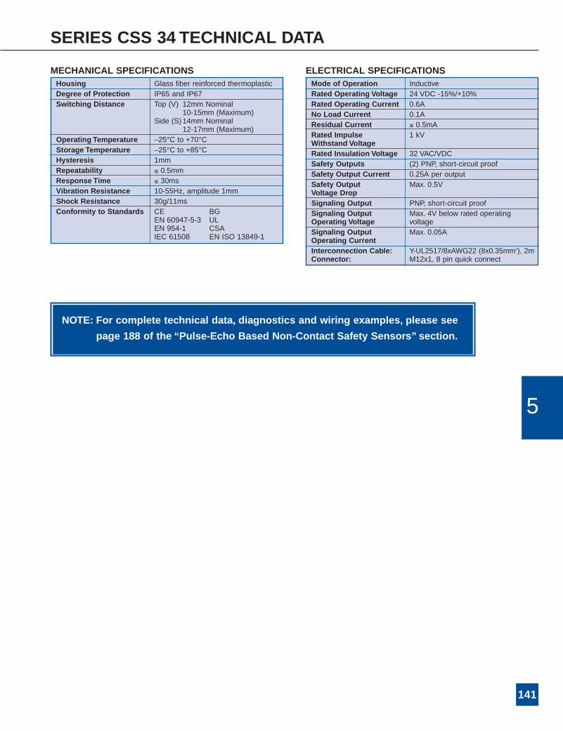
SERIES CSS 34 TECHNICAL DATA
NOTE: For complete technical data, diagnostics and wiring examples, please see
page 188 of the “Pulse-Echo Based Non-Contact Safety Sensors” section.
5
ELECTRICAL SPECIFICATIONSMode of Operation InductiveRated Operating Voltage 24 VDC -15%/+10%Rated Operating Current 0.6ANo Load Current 0.1AResidual Current ≤ 0.5mARated Impulse 1 kVWithstand VoltageRated Insulation Voltage 32 VAC/VDCSafety Outputs (2) PNP, short-circuit proofSafety Output Current 0.25A per outputSafety Output Max. 0.5VVoltage DropSignaling Output PNP, short-circuit proofSignaling Output Max. 4V below rated operatingOperating Voltage voltageSignaling Output Max. 0.05AOperating CurrentInterconnection Cable: Y-UL2517/8xAWG22 (8x0.35mm2), 2mConnector: M12x1, 8 pin quick connect
Housing Glass fiber reinforced thermoplasticDegree of Protection IP65 and IP67Switching Distance Top (V) 12mm Nominal
10-15mm (Maximum)Side (S)14mm Nominal
12-17mm (Maximum)Operating Temperature –25°C to +70°CStorage Temperature –25°C to +85°CHysteresis 1mmRepeatability ≤ 0.5mmResponse Time ≤ 30msVibration Resistance 10-55Hz, amplitude 1mmShock Resistance 30g/11msConformity to Standards CE BG
EN 60947-5-3 ULEN 954-1 CSAIEC 61508 EN ISO 13849-1
MECHANICAL SPECIFICATIONS
142
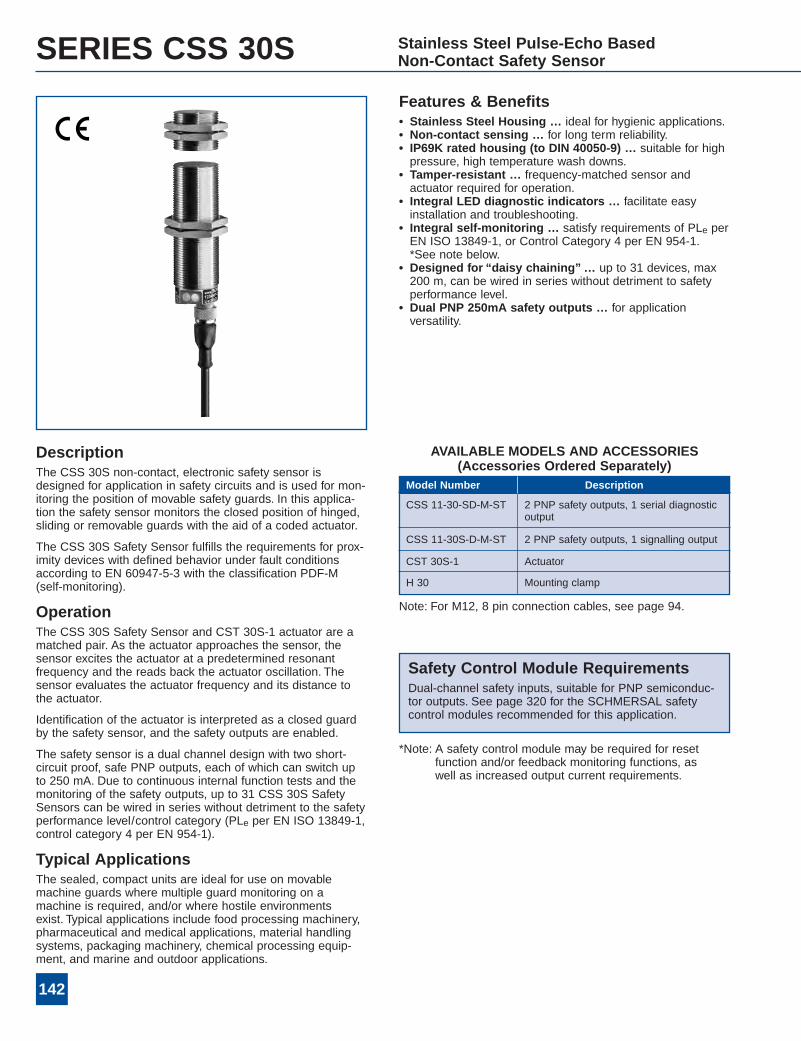
SERIES CSS 30S Stainless Steel Pulse-Echo BasedNon-Contact Safety Sensor
Features & Benefits• Stainless Steel Housing … ideal for hygienic applications.• Non-contact sensing … for long term reliability.• IP69K rated housing (to DIN 40050-9) … suitable for highpressure, high temperature wash downs.
• Tamper-resistant … frequency-matched sensor andactuator required for operation.
• Integral LED diagnostic indicators … facilitate easyinstallation and troubleshooting.
• Integral self-monitoring … satisfy requirements of PLe perEN ISO 13849-1, or Control Category 4 per EN 954-1.*See note below.
• Designed for “daisy chaining”… up to 31 devices, max200 m, can be wired in series without detriment to safetyperformance level.
• Dual PNP 250mA safety outputs … for applicationversatility.
DescriptionThe CSS 30S non-contact, electronic safety sensor isdesigned for application in safety circuits and is used for mon-itoring the position of movable safety guards. In this applica-tion the safety sensor monitors the closed position of hinged,sliding or removable guards with the aid of a coded actuator.
The CSS 30S Safety Sensor fulfills the requirements for prox-imity devices with defined behavior under fault conditionsaccording to EN 60947-5-3 with the classification PDF-M(self-monitoring).
OperationThe CSS 30S Safety Sensor and CST 30S-1 actuator are amatched pair. As the actuator approaches the sensor, thesensor excites the actuator at a predetermined resonantfrequency and the reads back the actuator oscillation. Thesensor evaluates the actuator frequency and its distance tothe actuator.
Identification of the actuator is interpreted as a closed guardby the safety sensor, and the safety outputs are enabled.
The safety sensor is a dual channel design with two short-circuit proof, safe PNP outputs, each of which can switch upto 250 mA. Due to continuous internal function tests and themonitoring of the safety outputs, up to 31 CSS 30S SafetySensors can be wired in series without detriment to the safetyperformance level/control category (PLe per EN ISO 13849-1,control category 4 per EN 954-1).
Typical ApplicationsThe sealed, compact units are ideal for use on movablemachine guards where multiple guard monitoring on amachine is required, and/or where hostile environmentsexist. Typical applications include food processing machinery,pharmaceutical and medical applications, material handlingsystems, packaging machinery, chemical processing equip-ment, and marine and outdoor applications.
Safety Control Module RequirementsDual-channel safety inputs, suitable for PNP semiconduc-tor outputs. See page 320 for the SCHMERSAL safetycontrol modules recommended for this application.
*Note: A safety control module may be required for resetfunction and/or feedback monitoring functions, aswell as increased output current requirements.
Note: For M12, 8 pin connection cables, see page 94.
CSS 11-30-SD-M-ST 2 PNP safety outputs, 1 serial diagnosticoutput
CSS 11-30S-D-M-ST 2 PNP safety outputs, 1 signalling output
CST 30S-1 Actuator
H 30 Mounting clamp
Model Number Description
AVAILABLE MODELS AND ACCESSORIES(Accessories Ordered Separately)

143
SERIES CSS 30S TECHNICAL DATA
5
ELECTRICAL SPECIFICATIONSMode of Operation InductiveRated Operating Voltage 24 VDC -15%/+10%Rated Operating Current 0.6ANo Load Current 0.1AResidual Current ≤ 0.5mARated Impulse 0.8kVWithstand VoltageRated Insulation Voltage 32 VAC/VDCSafety Outputs (2) PNP, short-circuit proofSafety Output Current 0.25A per outputSafety Output Max. 0.5VVoltage DropSignaling Output PNP, short-circuit proofSignaling Output min. (Ue – 5 V)Operating VoltageSignaling Output Max. 0.05AOperating Current
Housing Stainless SteelDegree of Protection IP67 to IEC/EN 60529
IP69K to DIN 40050-9Switching Distance 11mmOperating Temperature –25°C to +65°CStorage Temperature –25°C to +85°CHysteresis < 2mmRepeatability < 1mmResponse Time < 60msVibration Resistance 10-55Hz, amplitude 1mmShock Resistance 30g/11msConformity to Standards CE UL
IEC 60947-5-3 CSAIEC 61508 EN ISO 13849-1TUV EN 954-1
MECHANICAL SPECIFICATIONS
NOTE: For complete technical data, diagnostics and wiring examples, please see
page 194 of the “Pulse-Echo Based Non-Contact Safety Sensors” section.

144
SERIES CSS 16 Pulse-Echo BasedNon-Contact Safety Sensor
CST16-1 Actuator
Features & Benefits• Non-contact sensing … for long term reliability.• Sealed for moisture protection … ideal for most hostileenvironments.
• Tamper-resistant … frequency-matched sensor andactuator required for operation.
• Integral LED diagnostic indicators … facilitate easyinstallation and troubleshooting.
• Integral self-monitoring … satisfy requirements of PLe perEN ISO 13849-1, or Control Category 4 per EN 954-1.*See note below.
• Designed for “daisy chaining”… up to 16 devices, max200 m, can be wired in series without detriment to safetyperformance level.
• Dual PNP 500mA safety outputs … for applicationversatility.
• Same mounting dimensions as Series AZ16 … idealalternative in applications with alignment problems or harshenvironments.
DescriptionThe CSS 16 non-contact, electronic safety sensor is designedfor application in safety circuits and is used for monitoring theposition of movable safety guards. In this application the safe-ty sensor monitors the closed position of hinged, sliding orremovable guards with the aid of a coded actuator.
The CSS 16 Safety Sensor fulfills the requirements for prox-imity devices with defined behavior under fault conditionsaccording to EN 60947-5-3 with the classification PDF-M(self-monitoring).
OperationThe CSS 16 Safety Sensor and CST 16-1 actuator are amatched pair. As the actuator approaches the sensor, thesensor excites the actuator at a predetermined resonantfrequency and the reads back the actuator oscillation. Thesensor evaluates the actuator frequency and its distance tothe actuator.
Identification of the actuator is interpreted as a closed guardby the safety sensor, and the safety outputs are enabled.
The safety sensor is a dual channel design with two short-circuit proof, safe PNP outputs, each of which can switch upto 500 mA. Due to continuous internal function tests and themonitoring of the safety outputs, up to 16 CSS 16 SafetySensors can be wired in series without detriment to the safetyperformance level/control category (PLe per EN ISO 13849-1,or control category 4 per EN 954-1).
Typical ApplicationsThe sealed, compact units are ideal for use on movablemachine guards where multiple guard monitoring on amachine is required, and/or where hostile environmentsexist. Typical applications include printing machinery, textilemachinery, paper converting equipment, material handlingsystems, packaging machinery, chemical processing equip-ment, and woodworking machinery.
Safety Control Module RequirementsDual-channel safety inputs, suitable for PNP semiconduc-tor outputs. See page 320 for the SCHMERSAL safetycontrol modules recommended for this application.
*Note: A safety control module may be required for resetfunction and/or feedback monitoring functions, aswell as increased output current requirements.
CSS-8-16-2P-Y-L Series device with double pre-wired cable
CSS-8-16-2P-E-L End or single device with pre-wired cable
CSS-8-16-2P+D-E-L End or single device with diagnosticoutput, pre-wired cable
CSS-8-16-2P+D-M-L Series device with diagnostic output,pre-wired cable
CST-16-1 Actuator
Sensors available with M12 cable connector – Add ST after L incatalog number. See page 94 for M12 connector cables (4-, 5-, or8-pin).
Model Number Description
AVAILABLE MODELS AND ACCESSORIES(Accessories Ordered Separately)

145
SERIES CSS 16 TECHNICAL DATA
5
ELECTRICAL SPECIFICATIONSMode of Operation InductiveRated Operating Voltage 24 VDC -15%/+10%Rated Operating Current 1.1ANo Load Current 0.05AResidual Current ≤ 0.5mARated Impulse 0.8kVWithstand VoltageRated Insulation Voltage 32 VAC/VDCSafety Outputs (2) PNP, short-circuit proofSafety Output Current 0.5A per outputSafety Output Max. 0.5VVoltage DropSignaling Output PNP, short-circuit proofSignaling Output Max. 4V below rated operatingOperating Voltage voltageSignaling Output Max. 0.05AOperating Current
Type Interconnection 4x0.5mm2, 5x0.34mm2, orCable 7x0.25mm2
MECHANICAL SPECIFICATIONSHousing Glass fiber reinforced thermoplasticDegree of Protection IP67/IP65Switching Distance 8mm (Nominal)
7.0mm to 11mm (Maximum)Operating Temperature –25°C to +55°C for max. output
current ≤ 500mA/output–25°C to +65°C for output current
≤ 200mA/output–25°C to +70°C for output current
≤ 100mA/outputStorage Temperature –25°C to +85°CHysteresis max. 1mmRepeatability < 0.5mmResponse Time ≤ 30msVibration Resistance 10-55Hz, amplitude 1mmShock Resistance 30g/11msConformity to Standards CE BG
IEC 61508 ULIEC 60947-5-3 CSAEN ISO 13849-1 EN 954-1
NOTE: For complete technical data, diagnostics and wiring examples, please see
page 212 of the “Pulse-Echo Based Non-Contact Safety Sensors” section.

146
Saferby
Design