Embed Size (px)
Citation preview

PowerTronics
PQR Series Model D50
User’s Manual
PowerTronics 143 Raymond Road - Box 735
Candia, N.H. 03034 (603) 483-5876
http://www.powertronics.com

PQR Series Model D50
Page 2
www.Powertronics.com
All information and specifications written or implied in this manual are current at the time of printing. However due to ongoing process of adding improvements to the products, PowerTronics / Eastern Time Designs, Inc. reserves the right to make changes at any time without notice.
Copyright 2003 EASTERN TIME DESIGNS, INC.
SAFETY NOTICE
The power cable attached to the device is supplied with a safety and reference ground. Do not use the PQR D50 when powered from an ungrounded outlet.
High voltage exists at many points inside the cabinet. Qualified personnel ONLY! should open the covers. Opening the covers may affect the warranty.

PQR Series Model D50
Page 3
www.Powertronics.com
Table of Contents
PQR D50
Table of Contents 3 Warranty 5 Introduction 6 Calibration 7 Features 8 Testing with the PQR D50 9 Power Up Sequence 10 Connecting to the PQR D50 11
PQR Host Communications Software
Installing the PQR Host Communications Software 13 File Menu 15 View Menu 16 Settings Menu 17 Communications Menu 20
Other Terminal Communications
PQR D50 Commands 27 C0 - Transmit the Command Menu 28 C1 - Transmit the Version Number 29 C2- Transmit a Summary Report 30 C3 - Transmit a Detail Report 31 C4 - Transmit a Data Log 32 C5 - Clear all events, and data log 33 C6 - Set the Date and Time 34 C90 - Continuous Voltage readings 39 CX - Hang up the Phone 40

PQR Series Model D50
Page 4
www.Powertronics.com
Chapter 3 (Specifications)
Channel Specifications: 41 Operating Specifications: 43 Mechanical Specifications: 43 Interface Specifications: 43
Chapter 4 (Power Terminology)
Types of Power Problems 44 Dropout - Power Failure 45 Sag 46 Impulse 47 Common Mode Noise 48 Surge 49 High Frequency Noise 50
Chapter 5 (Product List)
PQR Series 51 PQR D50 52 PQR 1010 53 PQR 2020 54 Detective Series 55 PI500 56 Probe Series 57

PQR Series Model D50
Page 5
www.Powertronics.com
18 MONTH WARRANTY
Eastern Time Designs, Inc. (PowerTronics ) warrants to the original retail purchaser that each PQR D50 SERIES Power line analyzer sold by PowerTronics or any authorized representative is free from defects in material and workmanship for 18 MONTHS from date of purchase.
In the event of malfunction or other indication of failure attributable directly to faulty workmanship and/or materials, Eastern Time Designs, Inc. (PowerTronics) will at its option, repair or replace the defective product, to whatever extent it shall deem necessary to restore the product to proper operating condition, provided the purchaser includes proof of the date of purchase of the product along with the defective product.
Please note that Eastern Time Designs, Inc. may replace the defective product with a new or re-manufactured functionally equivalent product of equal value.
Before returning a product for repair, the customer must call Eastern Time Designs, INC. (PowerTronics ) Customer Service at (603) 483-5876 for an RMA (Return Merchandise Authorization number). This number should be included with the customer's mailing address and telephone number when the product is returned. Products should be returned to:
PowerTronics: RMA # Attention : CUSTOMER SERVICE DEPARTMENT, 143 Raymond Rd. Candia, NH 03034.
During the first 18 months after the date of purchase, all labor and materials will be provided without charge. There shall be no warranty for either parts or labor after the expiration of 18 months from the date of purchase.
The customer shall be solely responsible for the failure of any Eastern Time Designs product, or component thereof resulting from accident, abuse, or misapplication of the product, and Eastern Time Designs assumes no liability as a consequence of such events under the terms of this warranty. Some states do not allow the exclusion of implied warranties, so the above exclusion may not apply to you. This warranty gives you specific legal rights and may also have other rights which vary from state to state.
PQR Series Model D50
Page 6
www.Powertronics.com
INTRODUCTION
This reference guide is designed to aid PQR D50 users in the interpretation of AC power line problems.
The PQR D50 monitor is made in the U.S.A. by PowerTronics. This unit will detect a wide range of power disturbances including spikes, sags, surges, common mode noise, dropouts, and high frequency noise on the Hot and Neutral line. The PQR D50 will also monitor Temperature and Humidity
The PQR D50 is one of a series of practical power line monitors, designed and priced to be outfitted to everyone who services or installs three phase electrical, and electronic equipment.
Electronic equipment is damaged more often by power disturbances than by fire, theft, and vandalism combined. Intermittent power problems are the most expensive hidden expense to the owners of microprocessor based equipment.
The PQR D50 is easy to use and provides immediate and long term information for the technician and customer to understand power line disturbances.
To monitor the AC line with the PQR D50, plug the line cord provided into a standard 110 volt or 220 volt outlet. After running an internal self test, the unit will start testing the Hot and Neutral lines.

PQR Series Model D50
Page 7
www.Powertronics.com
CALIBRATION
The PQR D50 monitors are designed to test the Power Line with a high degree of accuracy. In this unit all measurements are referenced to a state of the art, temperature compensated voltage source. It is recommended that each unit be calibrated annually by the factory as certain components may require calibration. The procedure typically takes seven days and will be provided upon request for a nominal fee. Mention CALIBRATION PROCEDURE when calling for an RMA number.
PQR Series Model D50
Page 8
www.Powertronics.com
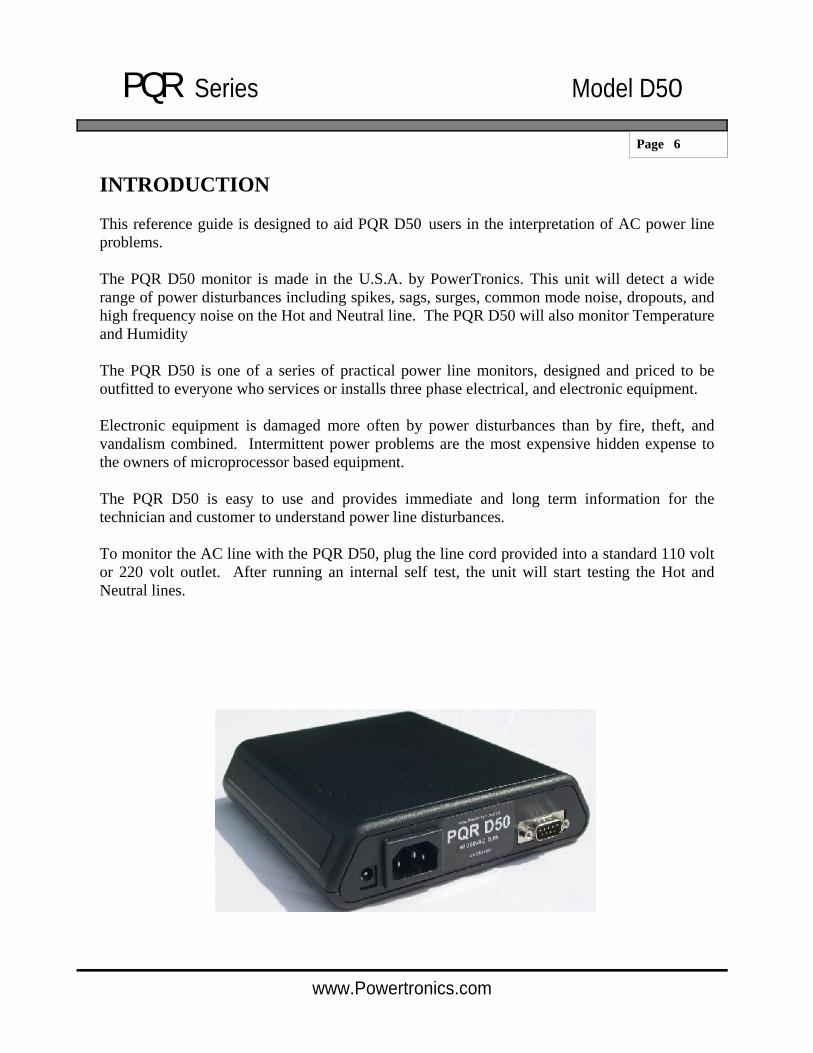
Monitor 2 AC Channels Hot and Neutral + Humidity and Temperature
User - Friendly Programmable Multiple Phase Monitoring Fast Impulse Detection Easy to Understand Reports Made in USA
The PQR D50 Power Line Analyzer provides a complete analysis of your AC Power for a fraction of the cost of other Monitors. Disturbances detected on the Hot and Neutral Lines , are recorded by their time, date, magnitude, and duration in a non-volatile RAM memory. This data is then retrieved from the analyzer through it’s serial communications port. The power to operate the unit comes from any standard 110v / 220v AC outlet. Once plugged in, the PQR D50 immediately begins testing the signals on the input connectors.
Features
Measures all types of disturbances
* Spikes * AC Voltage * Sags * Common Mode Noise * Line Frequency * High Frequency Noise * Dropouts * Power Failures * Surges
Simple to operate
1) Plug the power cord into a grounded outlet 2) Periodically connect to a computer for reports
Stores Disturbance events in non-volatile RAM * 32,000 Events in all * Will Data log all channels up to 32,000 readings (22.75 Days @ 1 sample per minute)
In addition to full Text Detail and Summary reports, event information such as the Magnitude, Time, and Date of each of the disturbances is also reported.
GRAPHICS SOFTWARE INCLUDED!
Provided with the PQR D50 is the PQR HOST COMMUNICATIONS Software. This software allows you to easily download the data and display or print the DATALOG chart over time, the PIE CHART of the summary of events or the HISTOGRAM of the detail of events.

PQR Series Model D50
Page 9
www.Powertronics.com
Testing with the PQR D50
The PQR D50 Single phase Voltage Power Quality Recorder is designed to obtain the maximum amount of useful data from the circuit under test, while requiring the minimum amount of setup time.
Data from the Hot, and the neutral line starts being collected as soon as power is applied to the AC power connector located on the back of the unit. Data will continue to be gathered until the unit is unplugged.
Long term voltage testing is known as Data Logging. The PQR D50 samples the voltage on each of the inputs continuously, and stores the average voltage once each minute. There is enough data storage capacity in the unit to collect these readings on all input channels for up to 20 days at 1 minute per sample.
The PQR D50 will continuously test the Hot and Neutral inputs for Sags, Surges, Power Failures, Dropouts, Impulses, High Frequency Noise, Line Frequency, and Phase changes. Any power quality problems that exceed the preset thresholds will be recorded in FLASH RAM, with the time and date stamp of the event. There is enough data storage capacity in the unit to collect up to 32,000 of these readings.

PQR Series Model D50
Page 10
www.Powertronics.com
TEMPERATURE PORT
HUMIDITY PORT
AC Power 90V - 260V AC 50/60 HZ
Apply AC Power:
There is a Unit Status LED on the back of the PQR D50. This led is used to indicate system diagnostics status, and Channel operational status.
When the PQR D50 is first connected to AC power (110VAC or 220 VAC), it will go through a series of power on diagnostics. The status of these tests can be seen in the Channel Status LED located on the back panel. While the initial tests are being executed, (approximately 10 seconds long) the Red LED will be blinking. After the tests are completed, the LED will turn off briefly, and then turn on steady.
The LED will blink for ten seconds, whenever there is a disturbance detected on any input, or the serial port has been accessed.
As soon as the diagnostics have completed, the PQR D50 is on-line, and monitoring the Hot and Neutral lines. The unit should be left on-line testing for at least a 72 hour period.
Back Panel Layout
PQR D-52 Power Quality Recorder
Status SERIAL PORT LED
DC Power
10-39v

PQR Series Model D50
Page 11
www.Powertronics.com
Connecting to the PQR D50
DIRECT:
The serial port connector on the back of the PQR D50 is a 9 pin DB style RS232. The pinout is as follows:
Pin 2 Receive Data Pin 3 Transmit Data Pin 5 Ground
A Null modem cable must be used to establish a connection between this port and a PC. This type of cable connects the Transmit Data pin on the PC to the Receive Data pin on the PQR D50, and the Transmit Data pin on the PQR D50 to the Receive Data pin on the PC. It also connects the Ground pins together.
The PQR D50 is configured to operate at 19,200 baud, with 8 data bits, 1 stop bit, and no parity checking. Select Xon/Xoff Communications protocol.
MODEM:
Use a straight cable (not a null modem) when connecting to a modem.
Power the PQR D50 and the Modem up at the same time after connecting the cable, and the PQR D50 will auto config the Hayse compatible Modem for auto answer mode, at 19,200 baud. If the modem is not Hayse compatible, configure it to answer the phone on 2 rings, with a Baud rate of 19,200, 8 data bits, 1 stop bit, and no parity checking.

PQR Series Model D50
Page 12
www.Powertronics.com
PQR Host Communications Software:
The PQR D50 is provided with the Powertronics Host Communications Software. When the PQR D50 is connected to a computer with a null modem cable, the Host software provides several functions:
Automatically connect to the PQR D50 Configure the PQR D50’s settings Download data from the D50 and Save on the computer Generate Reports, Charts and Graphs from the downloaded data

PQR Series Model D50
Page 13
www.Powertronics.com
Installing the PQR Host Communications Software
Go to www.powertronics.com, click on the support link and download the latest version of the software Or:
Put Disk 1 provided with your unit into your disk drive.
Select or Double click on SETUP A series of files will be copied to your computer’s RAM
To prevent any software conflicts, you should close any other applications programs running before continuing with the PQR Host software installation, then click on OK.
Click on the Computer Button to start the installation.

PQR Series Model D50
Page 14
www.Powertronics.com
Clicking on CONTINUE will allow the installation to complete.
The PQR Host communications software can now be started.
Click on START Select PROGRAMS Select POWERTRONICS
This Screen is the starting point for working with the PQR D50.
PQR Series Model D50
Page 15
www.Powertronics.com
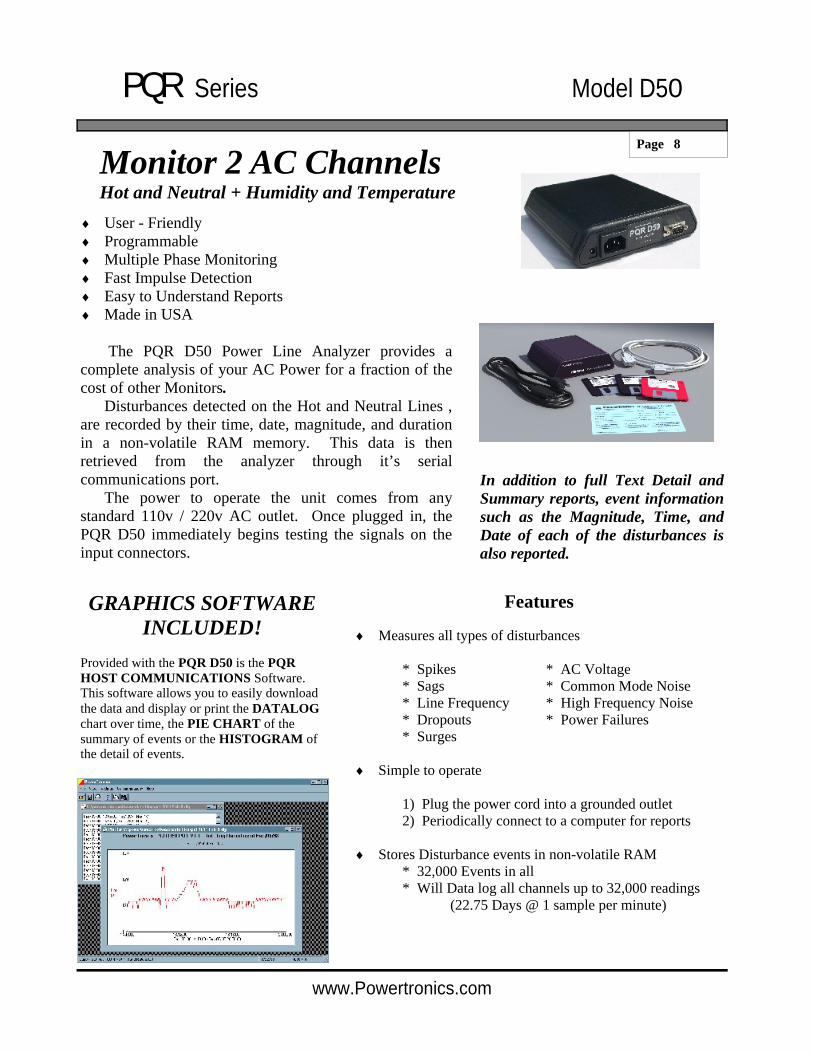
File Menu
The "File" menu contains options for using data files that are stored on disk. Open
Select the "Open" menu item to open a data log, detail report, or summary report that is stored on disk. After specifying the desired file, the program will open a window that contains the data from the file.
Close
Select the "Close" menu item to close the active window.
Print Select the "Print" option to send the active window to a printer. This menu item will display a Print Dialog for the user to select which printer to use and to specify the desired settings.
Memory Files The program will keep track of the last four files that have been used, and keep their names and locations in memory. To reopen any of these files, simply select the menu item with the desired file's name. The program will display the contents of the file in a new window.
Exit Select the "Exit" menu item to close all windows and exit the program.
Other options that are sometimes shown:
Save Select the "Save" menu item to save the active data file to its current file name and location.
Save As... Select the "Save As..." menu item to save the active data file to a new file name and location.

PQR Series Model D50
Page 16
www.Powertronics.com
View Menu
The "View" menu contains items used to control what tools are visible and available to the user in the main program window. Toolbar
Select the "Toolbar" menu item to toggle the toolbar. The toolbar contains the buttons for opening and printing files.
Status Bar
Select the "Status Bar" menu item to toggle the status bar at the bottom of the main program window. The status bar displays the program's current COM port and baud rate settings.

PQR Series Model D50
Page 17
www.Powertronics.com
Settings Menu
The "Settings" menu contains items that allow the user to specify certain settings for communication between the software and the PQR device. The menu also provides an interface for setting the PQR device parameters.
COM Port 1 - COM Port 4
The "COM Port" menu items are used to specify which computer COM port the PQR device is connected to. Selecting one of the options will change the program setting to that particular port. The current settings are indicated by a check mark next in the Settings menu. The current COM port setting is also displayed in the status bar at the bottom of the main program window. Set Date/Time
Select the "Set Date/Time" menu item to set the device date and time.
A dialog box will be displayed that provides the user an interface with which to specify the date and time. The settings will be defaulted to the current date and time, or to the date and time specified previously in the same program session.
After inputting the desired date and time, pressing the "Okay" button will instruct the program to set the device to the specified settings. This process may take a few seconds.

PQR Series Model D50
Page 18
www.Powertronics.com
Set Baud Rate
The "Set Baud Rate" menu option allows the user to specify the data rate to be used when communicating with the device. The program will display a dialog box with the six valid baud rates to select from: 1200, 2400, 4800, 9600, 14400, 19200 and 38400. After selecting the desired baud rate, pressing the "Okay" button will instruct the program to set the device baud rate. This process may take a few seconds. The program baud rate setting will also be set to the selected setting.
When the rate is changed, the new setting is saved in FLASH RAM, and is used as the power up default until the next time the setting is changed.

PQR Series Model D50
Page 19
www.Powertronics.com
Set Data Logger
The "Set Data Logger" menu item allows the user to specify the device data logging rate, or the time in between data log samples. The user will be provided six choices: 1 second, 5 seconds, 10 seconds, 30 seconds, 1 minute, or 4 minutes. After selecting the desired logging interval, pressing the "Okay" button will instruct the program to set the device setting. This process may take a few seconds.
When the rate is changed, the setting is NOT saved in non-volatile RAM. The power up default is one sample per minute.
Set Thresholds
The "Set Thresholds" menu item allows the user to specify the thresholds at which the device will trigger events. The user will be provided a dialog box with input fields to specify the surge, sag, and power failure thresholds for all available lines. Entering zero will set the unit to test at 5% and 10% limits. Entering a value between 1 and 999 will set the actual voltage for the unit to trip at. Leaving a field blank will keep the threshold set to its current value. After specifying the desired settings, pressing the "Okay" button will instruct the program to set the device settings. This process may take a few seconds

PQR Series Model D50
Page 20
www.Powertronics.com
Communications Menu
The "Communications" menu contains items that allow the user to retrieve data from the PQR device.
When you click on any of these functions, the PQR Host Communications software will automatically scan your serial ports looking for the connected PQR D50. The software will attempt to match the communications settings to the PQR D50, and will then perform the selected function.
For example, when you click on the Data Log report, the software will locate the PQR D50, and start downloading the data. The status of the download is reported as:
The blocks will count up until all of the data is downloaded and saved in the data file.

PQR Series Model D50
Page 21
www.Powertronics.com
Data Log
Selecting the "Data Log" menu item will download a listing of the voltages measured on all of the input channels since the unit was put on-line and the RAM was cleared. Before starting the transmission, the user will be asked to specify the name and location of a file to write the data to. After the transfer is complete, the program will automatically open a data window containing the downloaded data.
This is the text report showing the Date and Time of the reading, the voltage on each of the Hot and Neutral Lines as well as the readings from the Temperature and Humidity sensors.
Notice that the Graph option now shows up on your toolbar. Since you now have data available, you can generate the charts and graphs that represent that data.

PQR Series Model D50
Page 22
www.Powertronics.com
Data Log Graph
Select the Plot Time History selection under Graph
Select 1 or 2 of the available channels to graph
Once the channels are selected, and the Okay button is clicked, the software will scan the data file and generate a chart showing the data in chart form.
Data Log chart of Temperature and Humidity

PQR Series Model D50
Page 23
www.Powertronics.com
This is the chart generated from a days worth of data logging on a 120V AC Line.
By holding down your Left Mouse Button you create a selection box. You can drag your mouse, and create a ZOOM Area around your data. When you release the mouse button, the data in the ZOOM area is expanded to fill the screen area.
Double clicking on the chart will return it to original size.

PQR Series Model D50
Page 24
www.Powertronics.com
Detail Report
Selecting the "Detail Report" menu item will download a listing of all the disturbances saved since the unit was put on-line and the RAM was cleared. Before starting the transmission, the user will be asked to specify the name and location of a file to write the data to. After the transfer is complete, the program will automatically open a data window containing the downloaded data. Each event is described by the date, time, phase, event type, and magnitude of that disturbance..

PQR Series Model D50
Page 25
www.Powertronics.com
Summary Report
Selecting the "Summary Report" menu item will download a listing of counts of all the disturbances detected since the unit was put on-line and the RAM was cleared. Before starting the transmission, the user will be asked to specify the name and location of a file to write the data to. After the transfer is complete, the program will automatically open a data window containing the downloaded data. Each event is described by the phase, event type, magnitude, and quantity of that disturbance.
Selecting the Chart options from this report allows you to generate a pie chart showing the distribution of the detected events.

PQR Series Model D50
Page 26
www.Powertronics.com
Calibration Mode
Selecting the "Calibration Mode" menu item will command the device to begin transmitting the current voltage readings to the computer. The voltage readings are then displayed in a special window. The voltage readings will be updated approximately once a second. No other command can be performed while the program is in calibration mode. To end the transmission, user must press the "Stop Transmission" button; otherwise, the transmission will automatically stop after about two minutes.
Clear Data
Selecting the "Clear Data" menu item will clear all of the events and data log information stored in the internal battery backed RAM in the device. The summary report quantities will be reset to zero, and the data logging will start tracking voltage again. The program will ask the user for confirmation before transmitting the "Clear" command to the device.
Note: A large amount of time may be necessary in the cases where data is transmitted from the device to the computer. The exact duration is dependent upon the baud rate setting and the amount of data being downloaded. In these cases ("Data Log", "Detail Report", and "Summary Report"), a status window is displayed allowing the user to modify the progress of the transmission. The status window shows a running count of blocks written to disk during the current transmission. The block count provides an approximate measure of the amount of data that has been transferred, and the actual size of a block depends on the baud rate setting. The user can cut a transmission short by simply pressing the "Cancel" button.

PQR Series Model D50
Page 27
www.Powertronics.com
In the event that you would like to communicate with the PQR D50 without using the PQR Host Communications software, you can connect using most other terminal emulator software.
Commands:
The PQR D50 will respond to commands received through the serial port. All commands are started with a C. Entering C, followed by the command number will initiate the function.
The commands are as follows:
C0 Transmit the Command Menu C1 Transmit the Unit Version number
C2 Transmit a Summary Report C3 Transmit a Detail Report C4 Transmit a Data Log of recorded voltage
C5 Clear all events, and data log C6 Set the Date and Time
C90 Continuous transmission of channels readings
CX Hang up the phone .
After the PQR D50 has completed the task initiated by the operator command, it returns on-line to it’s monitoring duties. Each of the commands are detailed in the following pages.
Other Communications
PQR Series Model D50
Page 28
www.Powertronics.com
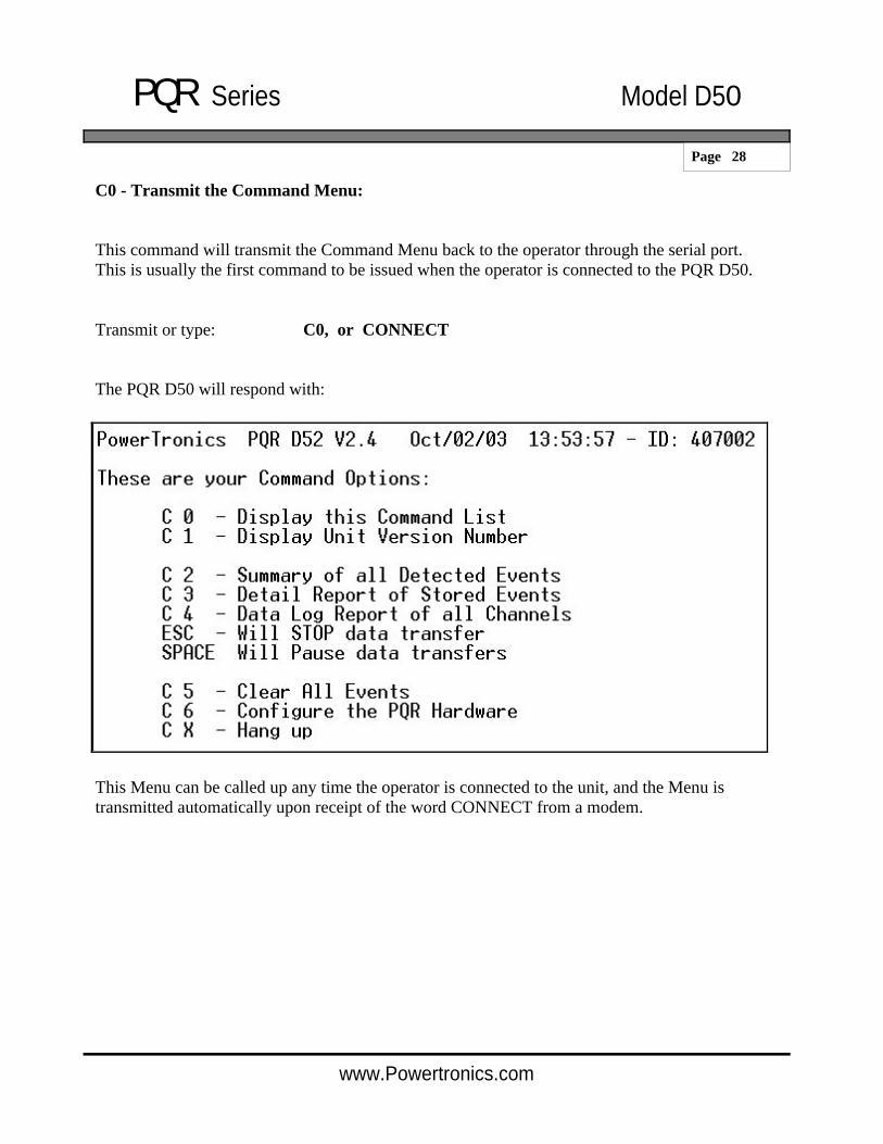
C0 - Transmit the Command Menu:
This command will transmit the Command Menu back to the operator through the serial port. This is usually the first command to be issued when the operator is connected to the PQR D50.
Transmit or type: C0, or CONNECT
The PQR D50 will respond with:
This Menu can be called up any time the operator is connected to the unit, and the Menu is transmitted automatically upon receipt of the word CONNECT from a modem.

PQR Series Model D50
Page 29
www.Powertronics.com
C1 - Transmit the Version Number:
This command will transmit the Model Name and Version Number back to the operator through the serial port.
Transmit or type: C1
The PQR D50 will respond with:
The Version Number refers to the Firmware Program stored in the PROM located inside the unit. This number is needed whenever the operator contacts PowerTronics technical support specialists.
PQR Series Model D50
Page 30
www.Powertronics.com
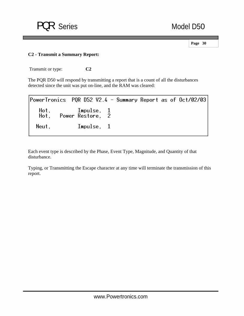
C2 - Transmit a Summary Report:
Transmit or type: C2
The PQR D50 will respond by transmitting a report that is a count of all the disturbances detected since the unit was put on-line, and the RAM was cleared:
Each event type is described by the Phase, Event Type, Magnitude, and Quantity of that disturbance.
Typing, or Transmitting the Escape character at any time will terminate the transmission of this report.

PQR Series Model D50
Page 31
www.Powertronics.com
C3 - Transmit a Detail Report:
Transmit or type: C3
The PQR D50 will respond by transmitting the Detail Report of all disturbances saved since the unit was put on-line and the RAM was cleared:
Each event is described by the Time, Date, Phase, Event Type, and Magnitude of that disturbance.
Typing or Transmitting the Escape character at any time will terminate the transmission of this report.

PQR Series Model D50
Page 32
www.Powertronics.com
C4 - Transmit a Data Log of input channels:
Transmit or type: C4
The PQR D50 will respond by transmitting the Listing of the voltages measured on all input channels each minute since the unit was put on-line, and the RAM was cleared:
The first line of the transmission has a header listing the Time and Date that the data logging was started. The following lines of the file are the voltage sample of the average voltage tested once each minute. The first character indicates if the reading was a minute or hourly reading.
Typing or Transmitting the Escape character at any time will terminate the transmission of this report.

PQR Series Model D50
Page 33
www.Powertronics.com
C5 - Clear all events, and data log:
This Command will clear all of the events, and all of the Data log information stored in the internal Battery backed RAM. The summary report quantities will be reset to zero and the Data Logging will start tracking voltage again.
Transmit or type: C5
The PQR D50 will respond by transmitting the following message
To clear the data, answer this question with a CAPITAL Y
The unit will then test and clear all internal RAM. The following text will be transmitted during the RAM clear operation.
Are You Sure you want to CLEAR ALL DATA on this board ? Y
Are You Sure you want to CLEAR ALL DATA on this board ? Y Testing RAM |————————————| - Ram test Passed Clearing Ram ......................... Done

PQR Series Model D50
Page 34
www.Powertronics.com
C6 - Configure the PQR Hardware:
This Command will transmit the Setup Command Menu back to operator through the serial port.
Transmit or type: C6
The PQR D50/52 will respond with:
This Menu can be called up anytime the operator is connected to the unit.
The Current Settings show how the PQR D50 are configured at the time.
PQR Series Model D50
Page 35
www.Powertronics.com
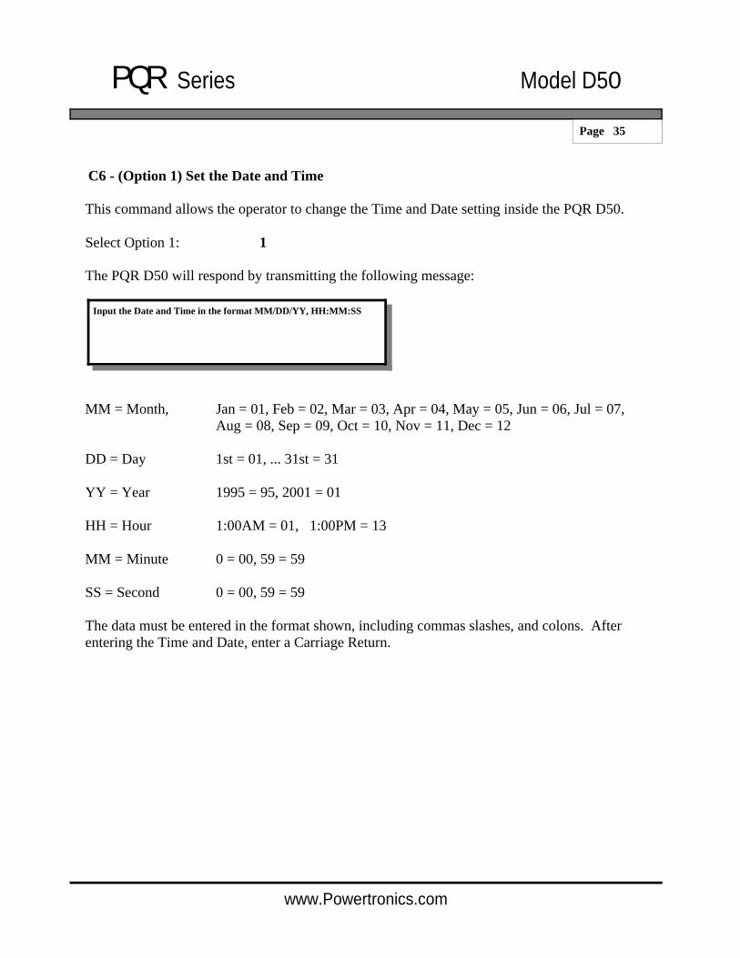
C6 - (Option 1) Set the Date and Time This command allows the operator to change the Time and Date setting inside the PQR D50.
Select Option 1: 1
The PQR D50 will respond by transmitting the following message:
MM = Month, Jan = 01, Feb = 02, Mar = 03, Apr = 04, May = 05, Jun = 06, Jul = 07, Aug = 08, Sep = 09, Oct = 10, Nov = 11, Dec = 12
DD = Day 1st = 01, ... 31st = 31
YY = Year 1995 = 95, 2001 = 01
HH = Hour 1:00AM = 01, 1:00PM = 13
MM = Minute 0 = 00, 59 = 59
SS = Second 0 = 00, 59 = 59
The data must be entered in the format shown, including commas slashes, and colons. After entering the Time and Date, enter a Carriage Return.
Input the Date and Time in the format MM/DD/YY, HH:MM:SS

PQR Series Model D50
Page 36
www.Powertronics.com
C6 - (Option 2) Set the Baud Rate:
This Command allows the operator to change the communications Baud rate setting inside the PQR D50.
Select Option 2: 2
The PQR D50 will respond by transmitting the following message:
Typing the number indicated next to the desired rate will change the rate of the PQR D50/52 immediately to the new rate.
Note: Changing the baud rate breaks down the connection between the PQR D50 and the communications devices must be changed to match the new rate of the PQR D50.
When the rate is changed, the new setting is saved in FLASH RAM, and is used as the power up default until the next time the setting is changed.
PQR Series Model D50
Page 37
www.Powertronics.com
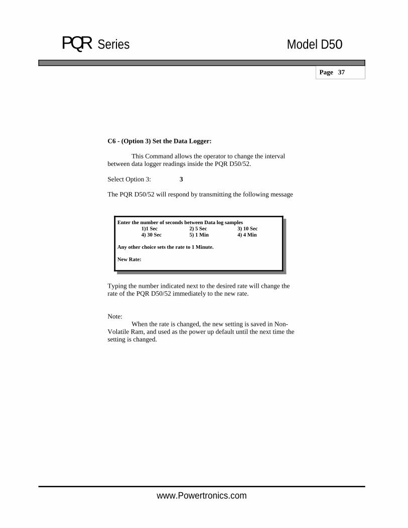
C6 - (Option 3) Set the Data Logger:
This Command allows the operator to change the interval between data logger readings inside the PQR D50/52.
Select Option 3: 3
The PQR D50/52 will respond by transmitting the following message
Typing the number indicated next to the desired rate will change the rate of the PQR D50/52 immediately to the new rate.
Note: When the rate is changed, the new setting is saved in Non-Volatile Ram, and used as the power up default until the next time the setting is changed.
Enter the number of seconds between Data log samples 1)1 Sec 2) 5 Sec 3) 10 Sec 4) 30 Sec 5) 1 Min 4) 4 Min
Any other choice sets the rate to 1 Minute.
New Rate:

PQR Series Model D50
Page 38
www.Powertronics.com
C6 - (Option 4) Set the Surge, Sag, and Power Fail:
This Command allows the operator to change the threshold points for the PQR D50/52 events.
Select Option 4: 4
The PQR D50/52 will respond by transmitting the following message
To set a fixed threshold, type the desired number of the setting:
To set the Temperature Surge setting to 98 degrees, type 98 at Temp channel - Surge Threshold.... : (5%, 10%).. : 98 followed by a carriage return.
The PQR D50/52 will respond (98), indicating that it will now trip at 98 degrees.
Note: These settings are saved in Non-Volatile FLASH RAM, and are used as the power up default.
AC channel - Surge Threshold....... : (5%, 10%).. : AC channel - Sag Threshold........... : (5%, 10%).. : AC channel - Power Failure............ : (5%, 10%).. :
DC Channel - Surge Threshold.......... : (5%, 10%).. : DC Channel - Sag Threshold.............. : (5%, 10%).. : DC Channel - Power Failure.............. : (5%, 10%).. :
Temp channel - Surge Threshold....... : (5%, 10%).. :

PQR Series Model D50
Page 39
www.Powertronics.com
C90 - Continuous Transmission of channels voltage:
This Command allows the operator to view the Voltage and Line Frequency present on each of the three channels, and neutral.
Transmit or type: C90
The PQR D50/52 will respond by transmitting the following:
The unit will send this reading continuously, resulting in the screen being updated about three times a second.
This command is helpful in confirming the unit is properly connected to the signals under test.
To quit the test, send any character to the unit, or wait for 30 seconds when the unit will return to the on-line testing mode on it’s own.
Unit Off-Line - entering Calibration mode
Hot: 120V Neu: 1V Temp: 72 Hum: 52 Unit returning to On-Line mode

PQR Series Model D50
Page 40
www.Powertronics.com
CX - Hang up the phone:
This Command allows the operator to disconnect the signal from a phone line on a Modem attached to the PQR D50/52.
Transmit or type: CX
The PQR D50/52 will respond by transmitting the following:
Having sent this message, the unit then sends the hang-up command to the modem. If there is a modem connected, and it had the phone off-hook, it would put the phone on-hook.
Thank you, and good bye.

PQR Series Model D50
Page 41
www.Powertronics.com
AC Channels Specifications
AC RMS Voltage
Range: 80 - 300 Vac RMS Accuracy: +/- 1.5% Sample rate: Programmable - range 1/second
to 1 reading per 4 minutes Input channels Two channels (Hot / neutral)
(or hot / hot). Sags/Surges:
Threshold: 5% and 10% of average RMS Duration limits: 1 cycle or 20 milliseconds Accuracy: +/- 1.5% Programmable User set values
Dropouts: Threshold: Less than 10V rms Duration limits: Longer than 8 ms, < than 80ms
Power Failure: Threshold: Less than 10V rms Duration limits: Longer than 80ms Programmable User set nominal values
Impulses: 2 Channels: 20V to > 2500 Vpeak Resolution: 20V, 70V, 140V, 300V, 850V, 2.5KV Accuracy: +/- 10% Pulse width: 500 nano seconds / threshold
High Frequency Noise: Range: 2 volts peak, 10 Khz - 10 Mhz Accuracy: +/- 10% Response time: 1 milli second
Line Frequency: Range: 40 - 400 Hz Accuracy: +/- 1% Response time: 1 AC cycle Threshold: +/- 2% deviation from average

PQR Series Model D50
Page 42
www.Powertronics.com
Environmental Specifications

PQR Series Model D50
Page 43
www.Powertronics.com
Operating Specifications
Temperature: 0 - 50 degrees C Humidity: 10% to 80% (non condensing) AC Voltage: 80 - 260 Volts AC (12 - 30 DC) AC Current: 0.1 amp Line Frequency: 40Hz - 400 Hz
Mechanical Specifications
Weight: 4 pounds Size: 8" wide x 10" deep, x 2" high Power Cord: 6 feet
Serial Interface Specifications
Connector: DB9 - RS 232C Baud Rate: 1200 -19200 (Programmable) Protocol: 8 Data, 1 Stop, No Parity bit

PQR Series Model D50
Page 44
www.Powertronics.com
Figure PT 1 Typical AC Waveform
Types of Power Problems and what they look like.
There are many types of power problems that can affect the quality of the AC power being delivered to a piece of equipment. Different types of problems will have different effects on the operation, or even life expectancy of this equipment. Knowing what these problems are, and what some of the consequences are of having these problems, can help in the process of identifying what can be done to help protect this equipment.
The following pages describe several of the more common types of Power disturbances and list what some of the causes are.
Dropout - Power Failure Sag Impulse Common Mode Noise Surge High Frequency Noise

PQR Series Model D50
Page 45
www.Powertronics.com
DROPOUT (NOTCH)
A condition where a portion of the sine wave has a lower than expected value or is missing entirely, usually for a portion of a cycle. These types of problems can be caused when large motors are started, Lightning arresters are employed (during a lightning hit), or when electrical equipment fails. Dropouts can lead to failures in computers and electronic equipment , reduced life of motors and flickering lights.
POWER FAILURE
When the duration of a dropout exceeds 1 cycle it is usually referred to as a Power Failure, or Blackout. This problem is the easiest to observe.
Figure PT 2 - Dropout

PQR Series Model D50
Page 46
www.Powertronics.com
SAG (UNDER-VOLTAGE, DIP, or BROWNOUT)
A power sag (or low line voltage) is a decrease in line voltage of at least 10% of the average line voltage for half a cycle or longer. The power sag is often caused by large inductive equipment (e.g. photocopy, postage equipment) being applied on the same AC line as is being tested. Sags can be caused by external factors as well, such as large power draining equipment used in other buildings. Sags can be particularly detrimental to electronic equipment because of the malfunctions caused by the sudden decrease of available voltage to the power supply. Complete failure rarely occurs, and often the equipment user continues to operate the device, unaware of the potential logic circuit problems that may have occurred.
Figure PT 3 - Sag
PQR Series Model D50
Page 47
www.Powertronics.com
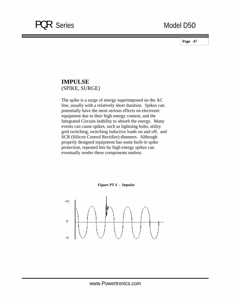
IMPULSE (SPIKE, SURGE)
The spike is a surge of energy superimposed on the AC line, usually with a relatively short duration. Spikes can potentially have the most serious effects on electronic equipment due to their high energy content, and the Integrated Circuits inability to absorb the energy. Many events can cause spikes, such as lightning bolts, utility grid switching, switching inductive loads on and off, and SCR (Silicon Control Rectifier) dimmers. Although properly designed equipment has some built-in spike protection, repeated hits by high energy spikes can eventually render these components useless.
Figure PT 4 - Impulse

PQR Series Model D50
Page 48
www.Powertronics.com
COMMON MODE NOISE
In single phase power systems, as found in many countries such as the USA, the load (computer or equipment) is connected between the hot and neutral line. Usually the neutral line is connected to earth ground at the service entrance, so that in effect the neutral line should have 0 volts at the load. At a typical site, voltage is induced onto the neutral line by other equipment. This voltage can appear in the form of impulses, or a continuous pseudo sine wave.
Figure PT 5 - Common Mode Noise

PQR Series Model D50
Page 49
www.Powertronics.com
SURGE (SWELL OR OVER-VOLTAGE)
A power surge is the opposite of a sag and is often referred to as "High Line Voltage". A surge is defined as an increase in line voltage above 128 volts (on a 115V Line) for a half cycle or longer. Like the sag, the power surge is often caused by large inductive loads being applied on the same line. Power surges cause some of the most dangerous occurrences, and their results are the most difficult to correct.
Figure PT 6 Surge
PQR Series Model D50
Page 50
www.Powertronics.com
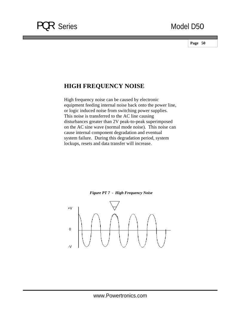
HIGH FREQUENCY NOISE
High frequency noise can be caused by electronic equipment feeding internal noise back onto the power line, or logic induced noise from switching power supplies. This noise is transferred to the AC line causing disturbances greater than 2V peak-to-peak superimposed on the AC sine wave (normal mode noise). This noise can cause internal component degradation and eventual system failure. During this degradation period, system lockups, resets and data transfer will increase.
Figure PT 7 - High Frequency Noise

PQR Series Model D50
Page 51
www.Powertronics.com
PQR Series Power Quality Recorders
For SINGLE, DUAL, THREE PHASE, and ENVIRONMENTAL applications.
User - Friendly Data Logging Multiple Channel Monitoring Fast Impulse Detection Easy to Understand Reports Reasonable Pricing Made in USA
The PQR Series of Power Quality Recorders are designed to meet a wide range of Power and Environmental testing needs. Models range from the simple - PQR D50, Single Phase to the Sophisticated - PQR 1010, Dual AC, Dual DC, Current, and Temperature recorder, with many Models in between.

PQR Series Model D50
Page 52
www.Powertronics.com
Measures all types of disturbances
* Spikes * AC Voltage * Sags * Common Mode Noise * Line Frequency * High Frequency Noise * Dropouts * Power Failures * Surges
Disturbance Threshold selectable by the operator
Simple to operate: 1) Plug cord into a grounded outlet 2) Let the unit monitor the line for 24-72 hours 3) Connect to computer for printouts
Stores events in non-volatile FLASH RAM
* 32,000 Event Storage * Data log 20 Days of readings
PQR D50
In addition to full Text Detail and Summary reports, event information such as the Magnitude, Time, and Date of each of the disturbances is converted to useful Pie and Bar Charts on your IBM Compatible PC.

PQR Series Model D50
Page 53
www.Powertronics.com
PQR 1010 User - Friendly Multi Channel - AC Voltage, DC Voltage, Current, Humidity and Temperature Disturbance Recorder and Voltage Logger Easy to Understand Reports Simple connection to a Computer or Terminal Made in USA
The PQR1010 Power Quality Recorder is a state of the art, fully integrated instrument which measures, records, and reports power disturbances, aiding in the analysis of power quality in medical, commercial and industrial applications. Disturbances detected on multiple channels are recorded by their time, date, magnitude, and duration in a non-volatile RAM memory. This data is then retrieved from the analyzer through its’ serial communications port. Connections to the PQR-1010 are made between the safety connectors on the back of the unit, and the circuit panel to be tested. The power to operate the unit comes from any standard 110v / 220v AC outlet. Once plugged in, the PQR-1010 immediately begins testing the signals on the input connectors.
Features
Measures all types of disturbances * Spikes * AC Voltage * Sags * Common Mode Noise * Line Frequency * High Frequency Noise * Dropouts * Power Failures * Surges * Data Logging
Simple to operate: 1) Connect the test leads to a service panel 2) Plug the power cord into a grounded outlet 3) Periodically connect to a computer for reports
Stores events in non-volatile FLASH RAM * 32,000 Event Storage * Stores the average reading every minute for up to 20 days on each channel
The PQR 1010 is one of a series of practical power line monitors, designed and priced to be outfitted to everyone who services or installs electrical, and electronic equipment.
In addition to full Text Detail and Summary reports, event information such as the Magnitude, Time, and Date of each of the disturbances is also reported.
GRAPHICS SOFTWARE INCLUDED!
Provided with the PQR 1010 is the PQR HOST COMMUNICATIONS Software. This software allows you to easily download the data and display or print the DATALOG chart over time, the PIE CHART of the summary of events or the HISTOGRAM of the detail of events.

PQR Series Model D50
Page 54
www.Powertronics.com
PQR 2020
User - Friendly Programmable Multiple Phase Monitoring Fast Impulse Detection Easy to Understand Reports Made in USA
The PQR2020 Power Disturbance Analyzer is a state of the art, fully integrated instrument which measures, records, and reports power disturbances, aiding in the analysis of power quality for AC power in medical, commercial and industrial applications. Power disturbances detected on multiple channels are recorded by their time, date, magnitude, and duration in a non-volatile RAM memory. This data is then retrieved from the analyzer through it’s serial communications port. Connections to the PQR-2020 are made between the safety connectors on the back of the unit, and the circuit panel to be tested. The power to operate the unit comes from any standard 110v / 220v AC outlet. Once plugged in, the PQR-2020 immediately begins testing the signals on the input connectors.
Three Phase Voltage Power Disturbance Monitor
By:
PowerTronics

PQR Series Model D50
Page 55
www.Powertronics.com
Measures all types of disturbances
* Spikes * AC Voltage * Sags * Common Mode Noise * Line Frequency * High Frequency Noise * Dropouts * Power Failures * Surges
Disturbance Threshold selectable by the operator
Simple to operate: 1) Plug cord into a grounded outlet 2) Let the unit monitor the line for 24-72 hours 3) Connect to printer or computer for printouts
Model D200 Shown
Stores events in non-volatile FLASH RAM
* 32,000 Event Storage * Data log 20 Days of readings
Easy to understand full 8-1/2” x 11” printed reports (when connected to a printer)
Immediate viewing of disturbance events and programming menus via the unit’s LCD display
D300 and D200 will test Temperature, The Ground line and DC Voltage
D300 is housed in a rugged carrying case, and has a built in printer
The “DETECTIVE” Series Models D200 & D300

PQR Series Model D50
Page 56
www.Powertronics.com
Full Function Power Disturbance Monitor
Very Low Cost
Measures all types of disturbances
* Spikes * AC Voltage * Sags * Common Mode Noise * Line Frequency * High Frequency Noise * Dropouts * Power Failures * Surges
Input Voltage Range 80 - 300 VAC
Simple to operate: 1) Plug cord into a grounded outlet 2) Let the unit monitor the line for 24-72 hours 3) Connect to printer for printouts
PI-500 Power Investigator
EASY TO USE, EASY TO UNDERSTAND, VERY LOW COST !
The Power Investigator generates a Cause and Effect Report which gives a clear understanding of what causes the type of power problems which were detected ON SITE. To fix the problems there’s no more guessing. The Power Investigator Solutions Guide Report helps you find the problems and make the right power protection decision.

PQR Series Model D50
Page 57
www.Powertronics.com
Probe 100 Monitor
Tool Box size monitor measures common-mode noise, spikes, high frequency noise, surges, sags, power failures, and power dropouts
Determines if the outlet is wired properly
Detects power problems quickly and economically
The PROBE continuously monitors the line for high or low AC line voltage conditions.
Simple to operate Plug it in, and press the Reset button Periodically check the LEDs
The Probe stores events until reset by operator !
The Probe is useful in identifying types of power disturbances that are on the line. It is like a snapshot of specific power problems. If you are having a problem with a computer system or peripheral, the Probe can be plugged into the same circuit and left for a period of time. When a problem is experienced with the equipment, immediate checking of the Probe’s LEDs will indicate the worst case power problem. If none of the LEDs are illuminated then the problem may be with the hardware. The LEDs that are illuminated indicate the types of disturbances that may be affecting the equipment. The LEDs on the Probe “latch” in the ON position when the device receives a disturbance.