Embed Size (px)
DESCRIPTION
June 21./22.,2007 GeoForschungsZentrum Potsdam 1.French-German Symposium on Geological Storage of CO 2 No.9 Abstracts 1.French-German Symposium on Geological Storage of CO 2 Number 1 No.9 Abstracts
Citation preview
1. French-German Symposium onGeological Storage of CO2
June 21./22., 2007GeoForschungsZentrum Potsdam
Abstracts
GEOTECHNOLOGIENScience Report
No. 9
1. French-German Symposium on Geological Storage of CO2
ISSN: 1619-7399
National R&D programmes on CO2 storage exist both in France and Germany. In France, theAgence Nationale de la Recherche (ANR) launched a CO2 programme in 2005. In Germany, theFederal Ministry of Education and Research (BMBF) launched research projects on CO2 storage inthe same year, as part of the R&D programme GEOTECHNOLOGIEN. The prime aim of the firstFrench-German Symposium is to bring together specialists on CO2 storage in order to increase thejointly held knowledge of CO2 storage R&D activities in both countries. A further objective of thesymposium is to initiate bi-lateral projects between the various research groups to enable benefitto be obtained from synergies of the expertise and skills available in the two countries.
The GEOTECHNOLOGIEN programme is funded by the Federal Ministry for
Education and Research (BMBF) and the German Research Council (DFG)
No.
91.
Fren
ch-G
erm
anSy
mpo
sium
onG
eolo
gica
lSto
rage
ofCO
2G
EOTE
CHN
OLO
GIE
NSc
ienc
eRe
port
Umschlag_SR09.qxd 25.05.2007 14:15 Uhr Seite 1

GEOTECHNOLOGIENScience Report
1. French-German Symposium onGeological Storage of CO2
June 21./22., 2007GeoForschungsZentrum Potsdam
Abstracts
No. 9
Number 1
SR09_FGS07.qxd 25.05.2007 14:43 Uhr Seite II

Impressum
SchriftleitungDr. Ludwig Stroink
© Koordinierungsbüro GEOTECHNOLOGIEN, Potsdam 2007ISSN 1619-7399
The Editors and the Publisher can not be held responsible for the opinions expressed and the statements made in the articles published, such responsibility resting with the author.
Die Deutsche Bibliothek – CIP Einheitsaufnahme
GEOTECHNOLOGIEN; 1. French-German-Symposium on Geological Storage of CO2
June 21./22., 2007, GeoForschungsZentrum Potsdam AbstractsPotsdam: Koordinierungsbüro GEOTECHNOLOGIEN, 2007(GEOTECHNOLOGIEN Science Report No. 9)ISSN 1619-7399
Bezug / DistributionKoordinierungsbüro GEOTECHNOLOGIENHeinrich-Mann-Allee 18/1914473 Potsdam, GermanyFon +49 (0)331-620 14 800Fax +49 (0)331-620 14 [email protected]
Bildnachweis Titel / Copyright Cover Picture: S. Schneider
SR09_FGS07.qxd 25.05.2007 14:43 Uhr Seite III

Preface
Several forecasting studies on energy policystrategies have prioritized – among the diffe-rent measures – the technologies for CO2
Capture and Storage (CCS) as a strong option,both for tackling the problems of climatechange and for boosting industry.
Therefore national R&D programmes on thistopic exist both in Germany and France. InGermany a portfolio of nine research projectsbetween academia and industry was startedwithin the framework of the national researchprogramme GEOTECHNOLOGIEN in summer2005. The projects funded by the FederalMinistry of Education and Research (BMBF)represent a key element in the organization ofGerman research in the field of geological sto-rage of CO2. In France, the Agence Nationalede la Recherche (ANR) launched a CO2 pro-gramme in the same year. These national pro-
grammes involve a large number of resear-chers from universities, research institutionsand private companies. In addition, severalFrench and German research teams are partici-pating and co-operating in the framework ofEU-funded projects.
The prime aim of the first French-GermanSymposium on the geological storage of CO2 isto bring together specialists on this topic inorder to increase the jointly held knowledge ofCO2 storage R&D activities in both countries. Itcovers the main aspects of the CO2 storage lifecycle, from site characterization and regionalassessment of storage capacities to long termsurveillance. A further objective of the sympo-sium is to initiate bi-lateral projects betweenthe various research groups to enable benefitto be obtained from synergies of the expertiseand skills available in the two countries.
SR09_FGS07.qxd 25.05.2007 14:43 Uhr Seite IV

SR09_FGS07.qxd 25.05.2007 14:43 Uhr Seite V
1
The CO2 pilot at Lacq: an integrated oxy-combustion CO2 capture and geological storage project in the South West of France
For decades to come, oil and gas will remainan energy source of choice to meet increasingdemand. But oil and gas operators have todevelop fields requiring much more processingand energy - i.e. very sour gases or extra heavyoils - while reducing the GHG emissions to mit-igate the climate change consequences.Among the possible options, carbon captureand geological storage (CCS) appears to be apromising option in addition to power efficien-cy increase or renewable energies use.Total launched end 2006 an integrated CCSproject in the South-West of France. It entailsthe conversion of a steam boiler into an oxy-fuel combustion unit, oxygen being used forcombustion rather than air to obtain a moreconcentrated CO2 stream easier to capture.The pilot plant, which will produce some 40 t/hof steam for use other facilities, will emit up to150,000 tons of CO2 over a 2-year period,which will be compressed and conveyed via
pipeline to a depleted gas field, 30 kilometersaway, where to be injected into a deep carbo-nate reservoir. CO2 injection is scheduled tobegin end 2008.The paper presents the characteristics of the30MWth oxy-boiler, one of the world firstindustrial oxy-combustion units. Then, it focu-ses on the critical issues that can be addressedwith an integrated project of combustion CO2
injection into a geological formation: CO2 puri-ty level required by each element of the CCSchain, validation of CO2 injection and migra-tion models, and validation of the methodolo-gies put in place to assess well and storageintegrity. It discusses also the potential applica-tion among others of such technology in anextra heavy oil »hot production« scheme withemphasis on the benefits to integrate allaspects of the CCS chain mentioned above forfuture large scale applications.
Aimard , N.
Total, France, CSTJF, Av. Larribau, 64018, Pau, Cedex
Figure 1:
Carbon capture & geologi-
cal storage in Lacq region.
SR09_FGS07.qxd 25.05.2007 14:43 Uhr Seite 1

Control of supercritical CO2 injectivityin the deep Dogger aquifer of the Paris basin from different injection scenarios
This work has been carried out in the frame-work of the »GeoCarbone-Injectivity« project,co-funded by the French National Agency forResearch (ANR). This 2-year project, still in pro-gress (Lombard et al., this Workshop), aims atstudying the near-well reservoir response to along-term injection of supercritical CO2. It isadmitted that massive injection of CO2 into areservoir will alter the physical and geochemicalsystem equilibria: pressure, temperature anddissolution of supercritical CO2 into the brinewill induce dissolution and precipitation reac-tions of the porous rock minerals. Volume chan-ges of the solid phase will then modify the porestructure, affecting both the porosity and thepermeability of the host rock. Indeed, the realchallenge is to define where the most importantchanges will occur within the reservoir and howthe CO2 injectivity will evolve in time.Through numerical simulations, this study focu-sed on determining the induced variations ofthe key-parameters of the reservoir (pressure,temperature, flow rate, porosity, permeability,aqueous and mineral compositions) and theirrespective feedback on CO2 injectivity. Thesimulations were performed using the multi-phase reactive transport code TOUGHREACT(developed by LBNL), considering a 2D radialgeometry around the injection well, applied tothe deep Dogger aquifer of the Paris basin.
Different injection scenarios were analysed inorder to estimate the relative weight of the cri-
tical parameters (pressure, temperature, flowrate) and their impact on reactive transport,first considered independently and then simul-taneously. The progressive integration in themodel of thermal, hydraulic, and chemical pro-cesses highlights the high reactivity of thenear-well area. Both compensating and ampli-fying processes were identified according tothe duration of the injection period and thelocalization of the injection well within thereservoir. Firstly, injected supercritical CO2 isdissolved into the aqueous solution thus incre-asing both water acidity and mineral dissolu-tion potential, favouring an increase in porosi-ty, which is beneficial to CO2 injectivity.However, following this initial step, numericalsimulations demonstrate that hydraulic proces-ses constrained by supercritical CO2 injectionare inducing a desiccation phenomenon in thenear-well porous medium. Irreducible water,entrapped in pores, sustains the increase inCO2 pressure. When the pressure is sufficient-ly high and under a continuous dry (i.e.without water vapour) CO2 flux, an evapora-tion process starts, leading to precipitation ofsalts and possibly secondary minerals.Although there has been little focus on thisdesiccation process in the literature until now,it nevertheless constitutes an important issueto be studied in order to understand the petro-physical impact of CO2 injection and, at theend, to be able to control the well injectivity.
André L. (1), Azaroual M. (1), Menjoz. A. (1), Kervévan C. (1), Lombard J.M. (2), Egermann P. (2), (3)
(1) BRGM - 3 Avenue C. Guillemin, BP 6009, F-45060 Orléans Cedex 2, France
(2) IFP – 1-4 Avenue de Bois Préau - 92500 Rueil-Malmaison, France
(3) Gaz de France, Avenue du Président Wilson, 93200 Saint-Denis-La-Plaine, France
2
SR09_FGS07.qxd 25.05.2007 14:43 Uhr Seite 2

3
RWE's IGCC-CCS-Project:Power generation with CO2 capture and storage.
RWE is a multi-utility company within thepower sector. Most of the electricity and heatis generated within RWE Power, the energy uti-lity within the RWE Group. Its activities arecentred in Western and Southern Germany,but RWE holds stakes in companies withinother European countries as well. Under theRWE Power roof there are over 18,000employees at work. Electricity of over 180 bil-lion kWh is generated every year from nuclearpower, lignite, hard coal, natural gas and rene-wables like hydropower. This covers one thirdof Germany’s electricity needs and makes RWEPower no. 1 in Germany and no. 2 in Europeamong electricity producers.
With an output of some 100 million tons perannum, RWE Power is the world’s biggest lig-nite producer. About 90 % of the lignite minedin the opencast operations at Garzweiler,Hambach and Inden is used to generate elec-tricity, while the remaining 10 % is upgraded
to make briquettes, pulverized lignite and cokeas well as fluidized-bed coal.
Coal not only is a major energy source inEurope, coal utilization also leads to considera-ble CO2 emissions. RWE aims to sustainablylower its CO2 emissions. The urgent task is tofurther develop the efficient and climate-spa-ring utilization of coal. The centrepiece ofRWE’s clean-coal activities is the implementa-tion of a zero-CO2 large-scale power plantwith integrated coal gasification plus CO2 cap-ture and storage (IGCC-CCS). If politics sup-ports this project, RWE wishes to commissionthe IGCC power plant in 2014. To successfully install the IGCC power plantplus pipeline and CO2 storage site, a lot of R&Dactivities are needed. In the field of CO2 stora-ge, R&D covers the development of a generalstorage methodology, technical input to theregulatory framework as well as on site testingof CO2 storage in different geological settings.
Asmus S. & Thielemann T.
RWE Power Aktiengesellschaft, Bereich Tagebauplanung und -genehmigung, Abteilung Markscheidewesen und
Lagerstätte (PBT-M), Stüttgenweg 2, 50935 Köln, E-Mails: [email protected], [email protected]
Figure 1: Image of the future IGCC-CCS power plant.
SR09_FGS07.qxd 25.05.2007 14:43 Uhr Seite 3

4
Determination of the capillary pressure charac-teristics of cover rock samples using mercuryporosimetry and water sorption experiments
A problem of particular importance for thegeological storage of CO2 in deep saline aqui-fers is the behaviour of cover rocks in contactwith the CO2 bubble. Capillary breakthroughof CO2 into the rock is a mechanism of specialinterest, hence the necessity to study closelythe porous network and the capillary proper-ties of the cover formations. We present herean attempt at determining the gas-liquid (sofar air-water) capillary pressure/water contentcurves of several rock samples from the Parisbasin, using the results from mercury porosi-metry and at establishing some connectionwith future water sorption experiments.
The intrusion of mercury into a dry rock can beassimilated to the one of air in a water-filledsample. It is thus possible to estimate the capil-lary pressure pc through the Laplace law, andto convert the mercury cumulative pore volu-me into rock water content θ. One thereforeobtains a portion of the pc (θ) curve, corre-sponding to pores over 3 nm diameter sincemercury cannot access finer structures. Thisexperimental curve can then be compared tosome theoretical form (in our case the functionproposed by Van Genuchten).
Mercury porosimetry experiments have beenperformed on the rock samples and optimiza-tion has then yielded an estimate of VanGenuchten’s parameters and of saturated/resi-dual values of water content in the rock.Available information therefore allows thedetermination of a rock-water diffusivity:
Relative permeability kr is calculated from theVan Genuchten’s equation based onMualem’s model, and intrinsic permeability ks
has been measured thanks to helium transferexperiments.
This diffusivity, introduced in a balance equa-tion, provides a self-sufficient model for unsa-turated flow. As mentioned above, this modelat this stage is not totally satisfactory since it isonly based on a part of the pc (θ) curve.
Water sorption experiments are currently in pro-gress. They will allow to complete pc (θ) curvefor small pore sizes and maybe to perfect ourunderstanding of the pore network since watervapour and mercury probably do not penetratethe rock in the same way (for instance they willprobably react differently to the presence ofbottlenecks). Simultaneously, the water trans-port model will be solved using a finite-elementssoftware and its results will be compared to theexperimental sorption profiles.
Bachaud P., Berne P.
CEA – DRT/LITEN/DTNM/L2T, CEA-Grenoble, 17 rue des Martyrs 38054 Grenoble cedex 9
4
SR09_FGS07.qxd 25.05.2007 14:43 Uhr Seite 4

5
Carbon dioxide sequestration based on alkaline residues
Amongst various CO2 sequestration scenarios,mineral trapping is regarded as one promisingtechnique because it warrants a permanentand inherently safe storage of CO2 (Lackner etal., 1995, Zevenhoven et al., 2006). The carbo-nation of Ca- and Mg-bound minerals is fairlysimple in process. Even so fast reaction kineticsare required for a technical realization. Theenergy input for the technical process isdependent on different materials and therefo-re the net amount of CO2 sequestered (Huijgenet al., 2006). Alkaline residues from combus-tion processes are favorable for CO2-bindingbecause they are cheap, highly reactive, andare generated as byproduct from the processof power generation.
In the present work, the reaction of alkalinebrown coal fly ashes with CO2 was studied inaqueous suspension in order to 1) develop atechnical process for carbonation that removesCO2 from flue gas of a powerplant sufficientlyfast and 2) to generate an alkalinity-containingsolution ready for the injection into deep aqui-fers. Laboratory experiments were performed inan autoclave system to measure the CO2 trans-fer as a function of solid-liquid ratios, CO2 par-tial pressure and stirring rates. Mild process con-ditions (25-50° C, atmospheric gas pressures)were chosen in order to evaluate the storagecapacity under low economic and energy costs.
We could achieve an uptake of more than 2moles CO2 per kg of the used fly ash.Considering the average amount of fly ash
accumulated within combustion process thiscorresponds to a reduction of about 1 per-cent of the CO2 emissions from a brown coalpower plant.
In alkaline residues, such as steel slags or wasteconcrete, CaO and MgO are suspected to bethe most important phases. In addition to thefly ash experiments we present first results ofthe CO2 reaction with CaO and MgO in orderto estimate the CO2 binding potential of otherfeedstock materials and to get a more-detailedprocess understanding.
Huijgen, W.J.J., Ruijg, G.J., Comans, R.N.J. andWitkamp, G.J. (2006): Industrial & Enginie-ering Chemistry Research, 45(26), 9184-9194.
Lackner, K.S., Wendt, C.H., Butt, D.P., Joyce,E.L. and Sharp, D.H. (1995): Energy, 20(11),1153-1170.
Zevenhoven, R., Eloneva, S. and Teir, S. (2006),Catalysis Today, 115(1-4). 73-79.
Back M. (1), Kühn M. (2), Peiffer S. (1)
(1) Hydrology, University of Bayreuth, Germany, [email protected], [email protected]
(2) Applied Geophysics, RWTH Aachen, Germany, [email protected]
SR09_FGS07.qxd 25.05.2007 14:43 Uhr Seite 5

6
Joint Project »COSMOS« CO2 Storage,Monitoring and Safety TechnologySP 3: Cap Rock Integrity
Injection of CO2 into saline aquifers will lead toan increase of formation pressure over a largearea. Subproject SP 3 investigates whether andto which extent large-scale pressurization willaffect cap rock integrity. It consists of experi-mental investigations on stress-strain beha-viour and permeability of representative rocksand numerical modelling of the large-scalebehaviour of the formation.
Experimental InvestigationsMain objective of the experimental investiga-tions is the simulation of the hydraulic loadingof specimens of intact clay stone and speci-mens with shear cracks. An innovative perme-
ability testing cell for high gradients allows dif-ferent operation modes (Fig. 1).Due to a lack of samples of the Keuper clay sto-nes forming the cap rock at Ketzin site at pre-sent a variation of clay stones is investigatedbeforehand. The critical gradient for a hydraulicbreakthrough has to be measured on intact spe-cimens and on specimens with shear cracks.
Intact specimens can be gained from »undi-sturbed« samples and also from reconsitua-ted powdered rock material by oedometriccompaction to a representative void ratio.Shear cracks in specimens are produced asring structures by a punching process under
Balthasar K. (1), Gudehus G. (1)., Hauser-Fuhlberg M. (2), Mutschler T. (1), Rübel S. (1),
Triantafyllidis T. (1) und Weidler P. (2)
(1) Universität Karlsruhe (TH), Institut für Bodenmechanik und Felsmechanik, 76128 Karlsruhe
(2) Universität Karlsruhe (TH), Institut für Mineralogie und Geochemie, 76128 Karlsruhe
Figure 1: Permeability testing cell in
a 200 kN load frame.
Figure 2: Ring structure in a silty clay stone produced by strain
rate controlled punching.
SR09_FGS07.qxd 25.05.2007 14:43 Uhr Seite 6
7
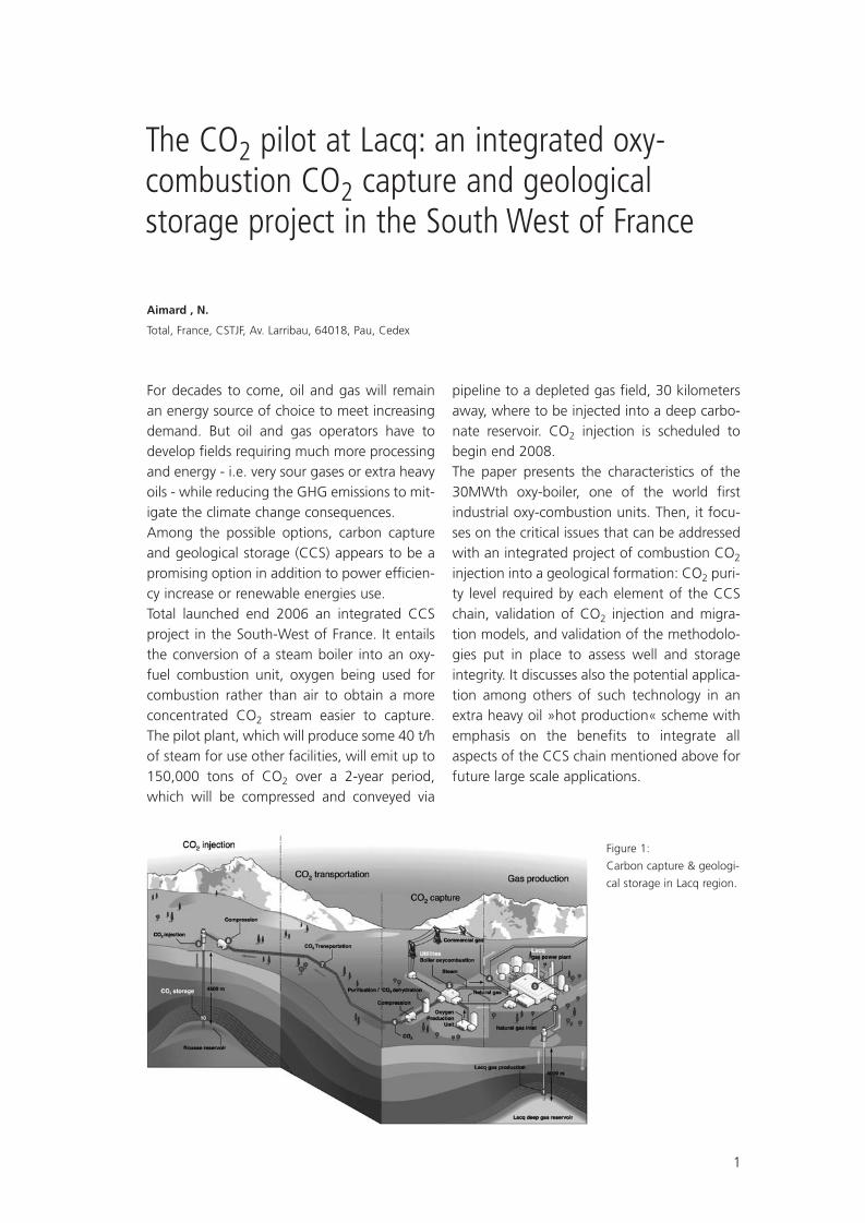
controlled deformation rate (Fig.2). Such ringstructures have well defined boundary condi-tions both for the permeability test and thenumerical simulation.
Numerical modellingThe geological structure of the numericalmodel is based on the LandMark-2-modelwhich was developed within the project CO2-SINK. The LandMark-2-model includes the pre-dicted surfaces of the geological layers in thesurrounding area of the projected injectionwell. The anticline structure of the Ketzin site isthe response to a gravitational uplift of a saltpillow in the Zechstein formation at a depth ofup to 2000 m. So the surfaces of the geologi-cal strata are no more horizontal.
Data from the world-stress-map give an orien-tation of the major principle horizontal stress inNE-SW-direction the minor being normal to it.The oval shape of the geological structure atKetzin site also indicates the directions of princi-pal horizontal stresses along its axis. Bending oflayers in the supra saliniferous formation due tothe gravitational uplift of the salt pillow reduces
original horizontal stress along the short axismore than in the long axis because of differentbending radii. Thus the minor horizontal stressfollows the direction of the short axis and majorhorizontal stress is normal to it (Fig.3).
For finite-element-modelling two differentmeshes have been created in two vertical crosssections along the main axes of the anticlinestructure at Ketzin. Thus the principal stressdirections are parallel and normal to themodel. Therefore model planes are vertical pla-nes rotated 60° from north direction (long axis)or 150° (short axis.
The development in space and time of the pres-sure due to CO2-injection can be applied to thetarget formation. The material of the geologicalformations shows elastic and / or viscous pro-perties. Large-scale deformation and the stain-rate of the cap rock due to CO2-injection can besimulated with this model (Fig.4).
Figure 3: Horizontal stress directions from bending
mechanism of the Ketzin anticline.
Figure 4: Development of pore pressure due to CO2-Injection.
SR09_FGS07.qxd 25.05.2007 14:43 Uhr Seite 7

8
Methane and CO2: Can we estimate storedvolumes by seismic measurements?
Methane is accumulated in underground sto-rage sites and is partly released in winter, whenthe consumption of domestic gas is high. Incooperation with Gaz de France and theCompagnie Générale de Géophysique, IFP hasearned a twenty-year experience in monitoringthe gas plumes and the substitution of gas forwater – or inversely – in underground confinedsaline aquifers.
Experience in gas storage monitoringThe fluid substitution has only a slight effecton the average density in the reservoir, deter-mined by the porosity, the gas saturation andthe difference of densities of the fluids. By con-trast, the P-wave velocity is more sensitive tofluid changes.
When the porosity and the bulk moduli areknown, the variation of the P-wave velocitycan be expressed as a function of the gas satu-ration via Gassmann's formulation (Gassmann,1951). The P-wave velocity decreases rapidly asgas appears in the water-filled pores, thereforeincreasing the compressibility of the porespace, up to a gas saturation of some 10 %.The P-wave velocity then increases slowly asthe gas saturation increases.
The rapid change in compressibility with theapparition of gas can lead to spectaculareffects, in particular in shallow sandstones.Estimation of the volume stored is a more dif-ficult problem, as it requires not only the deli-
mitation of the zone reached by the gas, butalso an estimation of the saturations withinthis volume.
According to Whitman and Towle (1992),when the gas saturation is over 30%, the P-wave velocity squared is approximately propor-tional to the water saturation and to the diffe-rence between water and gas densities, that is,
, where Kg and pbg denote the bulk modulus and density ofthe gas-filled rock, respectively, φ is the porosi-ty, Sw is the water saturation and
stands for the difference in fluid density. Thisrelationship has been used to estimate theporosity and saturation from the time shiftsmeasured on a seismic profile recorded over agas storage with receivers at depth (walk-away), giving a gas saturation varying between50 and 80% along the profile, with an error of± 10% (Dumont et al, 2001).
Further work with the same data has shownthat the P- and S-wave velocities are also sen-sitive to stress variations, contributing to timeshifts of the same order of magnitude as thefluid substitution effect (Vidal et al, 2002). Thestress influence could be estimated by using arelation of the form , where
Becquey M. (1), Bruneau J. (1), Huguet F. (2), Meunier J. (3),
Rasolofosaon P. (1), Vidal-Gilbert S. (1) & Dietrich M.* (1)
(1) IFP
(2) Gaz de France
(3) CGGVeritas
SR09_FGS07.qxd 25.05.2007 14:43 Uhr Seite 8

9
represents the mean effective stress and expo-nent h, the Hertz coefficient, is equal to of 1/6in the case of a stack of spherical grains, asstated in the Hertz-Mindlin theory (Mindlin,1949). Laboratory measurements performedon core samples yielded lower values of h forreal rocks both for P- and S-waves (Rasolo-fosaon et al, 2003).
In the case of the underground gas storage ofCéré-la-Ronde, central France, where thewater-bearing sandstone reservoir lies at some900 m depth, the measured values of theHertz coefficients were respectively 0.13 for S-waves and 0.09 for P-waves. The time shiftsbetween the end of the withdrawal periodand the end of the injection period are of theorder of one millisecond. A feasibility studybased on Gassmann's formulation for the fluidsubstitution effect and on the measured Hertz-Mindlin coefficients for stress effects conclu-ded that both effects have a comparableinfluence on the two-way travel times of seis-mic reflections generated beneath the reser-voir during the injection period, namely, about0.5 ms for the stress effect for a pressure vari-ation of 4 MPa, and 0.75 ms for the substitu-tion effect (Vidal et al, 2001). Both effects con-tribute to velocity variations in the same direc-tion within the reservoir. Indeed, the pore pres-sure increases with gas injection, therebydecreasing the effective stress, which in turncontributes to an additional decrease in veloci-ty. However, it should be noted that the stresseffect can extend beyond the limits of thereservoir.
The time picking accuracy for reservoirs loca-ted at depths less than 1000 meters can be aslow as 0.2 ms for carefully acquired and pro-cessed seismic data.
Carbon dioxide specificitiesFrom a geophysical point of view, carbon dio-xide differs from methane essentially by itsdensity, in particular when CO2 is in supercriti-cal state at depths greater than 700 or 800
meters. In this case, the density can reach 600kg/m3 or more, so that the density differencebetween gas and brine is reduced to about400 kg/m3, that is, less than half the differen-ce between the densities of methane (~ 100kg/ m3 at reservoir conditions) and water. As aresult, P-wave velocities are less sensitive toCO2 substitution and consequently, the esti-mation of the saturation will be more difficultfor CO2 than for methane.
Pressure effects will be comparable for storagein similar reservoirs. Methane is stored in stra-tigraphic traps. In depleted structures or in lowpermeability reservoirs, stress effects mighthave the largest influence on seismic parame-ters. However, when carbon dioxide is injectedinto flat or monocline aquifers of high perme-ability, the injected gas can freely move awayfrom the injection point, and the pore pressu-re will not change very much, except close tothe injection wells. In this case, no additionalstress effect will be expected.
The above discussion emphasizes the fact thatthe estimation of stored volumes of CO2 canrepresent a formidable challenge. One of thekey requirements to infer reliable gas satura-tion estimates from time-lapse seismic data isthe accuracy of time measurements.
Permanent source and receiversIn order to monitor the time variations withsufficient accuracy, permanent data acquisi-tion systems composed of a low-energy sour-ce and a vertical receiver array have beendeveloped and tested. The typical layout con-sists of a seismic source installed in a vault orcemented in a shallow borehole, and a seriesof sensors deployed in a nearby well at depthsranging from of a few tens of meters to seve-ral hundred meters (Meunier et al, 2001).
This configuration has been used to automati-cally record about ten Vertical Seismic Profiles(VSPs) per day over an underground gas stora-ge. The VSPs were processed to measure time
SR09_FGS07.qxd 25.05.2007 14:43 Uhr Seite 9

10
variations associated with injection and with-drawal cycles, and the observed time changeswere subsequently compared to the pressuremeasured at the bottom of a nearby well(Rodriguez et al, 2002, figure 1). Between peri-ods of injection, where the pore pressure rea-ches 11.5 MPa and periods of withdrawal,where the pore pressure falls down to 7 MPa,the time shifts measured between two reflec-tions above and below the reservoir reaches0.4 milliseconds. These real time shifts aresomewhat smaller than what was expectedfrom the feasibility study, however, the mainpoint is that they could actually be measured.The measurement accuracy has been estima-ted around 0.1 millisecond based on the erra-tic variations from trace to trace.
At a second gas storage, the same data acqui-sition pattern was used with a seismic sourceburied and cemented at a depth of 18 m. VSPswere processed (Bianchi et al, 2004) and thereflections were stacked over the receiverarray. However, in this survey, events reflectedat the surface were found to be sensitive totemperature and wetness changes in the near-surface and were subject to time variations of
the same order of magnitude than the timevariations expected from fluid substitution inthe reservoir. It was anticipated that deconvo-lution of the up-going reflected wave field bythe down-going wave field would resolve theproblem. However, the specificities of therecording array, far above the reservoir and inthe near-field of the seismic source, as well asthe presence of S-waves generated near thesurface, limited the effectiveness of the signaldeconvolution.
The stacked traces were stacked again over aduration of 15 days and displayed side by sidefor the whole recording period, which lastedfrom mid-November to the end of July.
In order to show the time shifts, several timewindows were selected, with a duration ofabout 100 ms (100-200, 200-280, 280-350,350-450 ms above the reservoirs, 450-550 msin the reservoir zone, 550-650, 650-750, 750-850, 850-920 ms below the reservoirs).
The time shifts computed by correlating eachtime window with its calendar time averageare displayed in figure 2. In this figure, the cor-
Figure 1: Comparison between the time shifts measured for the arrival time
of a reflector located below the gas-filled reservoir and the pressure measured
at the bottom of a nearby well.
SR09_FGS07.qxd 25.05.2007 14:43 Uhr Seite 10

11
relation of the 100-200 ms window is repres-ented around the upper baseline. The timescale is indicated by the interval between twosuccessive lines and represents one millise-cond. The difference between the largest andsmallest values for that time window is about0.1 ms, that is, of the order of the pickingaccuracy. The result of the correlation of the200-280 ms window is represented aroundthe second baseline and so on. Down to 450ms, it is seen that the time differences are verysmall, below 0.3 ms. Beneath the reservoirlevel, however, the time shifts reach 0.5 msand up to 1 ms for the deeper window. Underthe reservoirs, the time shifts show a minimumbetween March and April, at the end of thewinter when the reservoirs have been emp-tied. Conversely, the time shifts show a maxi-mum in July, during the injection.
The time shift curves below the reservoir arenot perfectly parallel due to noisy data. Inorder to improve the signal-to-noise ratio andestimate the effects of fluid substitution andstress, we took the average of the travel timepicked in the windows below the reservoirs.Figure 3 shows the time averages above thereservoirs (between 100 and 450 ms), withinthe reservoir zone (450-550 ms) and belowthe reservoirs (550 to 920 ms). The differencesbetween the minimum and maximum values
are 0.14 ms above the reservoirs, 0.35 ms inthe reservoir zone, and 0.50 ms below.
ConclusionSubstitution of methane for water in aquifersused for underground gas storage leads tovariations in the subsurface properties that canbe detected and measured with active seismicinvestigations. The most obvious indicator ofthe fluid substitution is a modification of thetravel times for waves passing through thegas-filled reservoirs. These modifications canactually be measured provided that the seismicdata are carefully acquired and processed andif stress effects are taken into account. In favo-rable cases, the gas saturation can be inferredfrom the measurements. The sensitivity of theP-wave velocities to gas saturation will belower in the case of carbon dioxide than it isfor methane, implying that the estimation ofthe CO2 saturation will require very accuratemeasurements.
AcknowledgmentsWe thank the »Fonds de Soutien aux Hydro-carbures« for supporting a twenty-year longcooperation on the subject of gas storage mo-nitoring. We also thank the »Agence Nationalede la Recherche« for funding a project dedica-ted to the geological storage of CO2.
Figure 2: Correlation time shifts in successive time windows.
The reservoirs are located between 470 ms and 550 ms.
SR09_FGS07.qxd 25.05.2007 14:43 Uhr Seite 11

12
ReferencesBianchi T., Forgues E., Meunier J., Huguet F.and Bruneau J., 2004, Acquisition and Pro-cessing Challenges in Continuous ActiveReservoir Monitoring, SEG Expanded Abstracts,23, 2263-2266.
Dumont M.H., Fayemendy C., Mari J.L. andHuguet F., 2001, Underground gas storage:estimating gas column height and saturationwith time lapse seismic, Petroleum Geo-sciences, 7, 155-162.
Gassmann, 1951, Über die Elastizität poröserMedien, Vierteljahrsschrift der Naturforschen-den Gesellschaft in Zürich, 96, 1-23.
Meunier J., Huguet F. and Meynier P., 2001, Re-servoir monitoring using permanent sourcesand vertical receiver antennae: The Céré-la-Ronde case study, The Leading Edge, 20, 622-629.
Mindlin, R.D., 1949, Compliance of elasticbodies in contact, J. Appl. Mech., 16, 259-268.
Rodriguez S., Meynier P., Meunier J. andHuguet F., 2002, Reservoir monitoring usingpermanent sources and vertical receiver anten-nae: The Céré-la-Ronde case study, 17thWorld Petroleum Congress, 383-392.
Rasolofosaon P. and Zinszner B., 2003, Petro-acoustic characterization of reservoir rocks forseismic monitoring studies. Laboratory measu-rement of Hertz and Gassmann parameters,Oil and Gas Science and Technology – Revuede l'IFP, 58, 615-635.
Vidal S., Jardin A. and Huguet F., 2001,Feasibility Study of Time-Lapse Estimate forMean Effective Stress and Saturation Changesin Gas Storage, SEG Expanded Abstracts, 20,1648-1651.
Vidal S., Huguet F. and Mechler P., 2002,Characterizing reservoir parameters by inte-grating seismic monitoring and geomechanics,The Leading Edge, 21, 295-301.
Whitman W.W. and Towle G.H., 1992, Theinfluence of elastic and density properties onthe behavior of the Gassmann relation, TheLog Analyst, Nov-Dec 92, 500-506.
Figure 3: Average time shifts above, within and below the reservoirs as a
function of calendar time.
SR09_FGS07.qxd 25.05.2007 14:43 Uhr Seite 12

13
SR09_FGS07.qxd 25.05.2007 14:43 Uhr Seite 13

14
The Geocarbone-Carbonatation Project: [bio]mineralization of carbon: From experiments tonumerical simulations.
In the past five years, increasing fundamentalresearches have focused on the short and longterm effects of the massive injection of anthro-pogenic carbon dioxide in various geologicalenvironments. A growing scientific community,including the Geocarbone-Carbonatation pro-ject team, is now studying the coupling bet-ween biological, geochemical, mechanical andhydrodynamic processes arising as a result ofthe strong thermodynamical disequilibriumcaused by the injection of large amount of CO2
and the consecutive modification of the pH ofthe formation waters. In addition, the modifi-cation of the deep communities' structure andmetabolism induced by the injected CO2 andthe complex kinetics associated with biologi-cally-induced precipitation of carbonates arenow thought to represent key aspects of themineralization processes. Finally, dissolutionand precipitation can modify the hydrodyna-mic and mechanical properties of the reservoir,inducing permanent deformations and eventu-ally failure, strong modifications of the storagevolume and of the transport properties.
The Geocarbone-Carbonatation project hasbeen funded by the French National ResearchAgency (ANR) in 2006-2008. It is supported bya consortium of research institutions (CNRS,École des Mines de Saint-Étienne, École desPonts, IFP) and companies (Gaz de France,Total and Schlumberger). In this project, newconcepts are now emerging to study the con-sequences and kinetics of the effects of injec-tion of CO2 in geological reservoirs, using well-controlled laboratory experiments and theore-tical tool. In particular, studies are now focu-sing on:1) the equilibrium and kinetics of carbonate
formation, which determine the extent andrate of formation of stable carbonate mine-rals, as well as the effect of organic or inor-ganic impurities in the precipitated minerals(LMTG, LGIT, IPGP, SCHLUMBERGER).
2) effect of CO2 on the deep biosphere meta-bolism and kinetics experiments associatedwith biologically-induced precipitation ofcarbonates (IPGP, LMTG). In parallel, newtools are being developed for (1) imagingof micro-organisms and carbonates precipi-
Bénézeth P. (1), Ménez B. (2), Bernard D. (3), Renard F. (4), Gouze P. (5), De Gennaro V. (6), Brosse E. (7),
Garcia D. (8), Rigollet C. (9), Lescanne M. (10), Barlet-Gouedard V. (11)
(1) LMTG, 31400 Toulouse, France
(2) IPGP, 75005 Paris, France
(3) ICMCB, 33608, Pessac, France
(4) LGIT, 38041 Grenoble, France
(5) TPHY, 34095 Montpellier, France
(6) Ecole des Ponts, 77455 Marne-la-Vallée, France
(7) IFP, 92500 Rueil-Malmaison, France
(8) Ecole des Mines, Saint-Etienne, France
(9) GDF, 93211 Saint Denis la Plaine, France
(10) TOTAL, 6400 Pau, France; 11Schlumberger, 92140 Clamart, France
SR09_FGS07.qxd 25.05.2007 14:43 Uhr Seite 14

15
tated to better constrain the processes invol-ved at the micrometric scale, (2) monitoringcarbonization processes through geophysical(measure of self potential variations) or geo-chemical tracers (stable isotopes),
3) reactive transport experiments (biotic andabiotic) at various scales (centimeter todecameter) and conditions (T, pCO2, solu-tion chemistry) realized on cores and pak-ked beds representatives of the geologicalreservoirs of the Paris Basins, namely theDogger and the Keuper (limestones andsandstones) (LMTG, ICMCB, IPGP, TPHY,LGIT, Ecole des Ponts, GDF, EMSE). Fromthese experiments various parameters aremeasured: solution chemistry, microtomo-graphy visualizations (to study the local dis-solution-precipitation mechanisms in coresof centimeter scale with resolutions of afew microns), impact of the crystallizationon the petrophysical and mechanical pro-perties (permeability, porosity, compressibi-lity and yielding …) so that both geochemi-cal, hydrodynamic and mechanical aspectsof the processes can be investigated,
4) the development of a computer model ofreactive transport from the microscopic topore scale (ICMCB, LMTG). Realistic microgeometry (from X-ray computed microtomography) can be handled permittingthe computation of the local concentrationfields for each considered constituents (six,H+, OH-, HCO3
-, Ca+, CO2* and CO3
2-, inthe present version where the solid is onlycomposed of calcite). Fluid flow is compu-ted solving Stokes equations. Assuminglocal electro neutrality and three speciationequilibriums (giving 4 relations betweenthe unknowns), the solution of two trans-port equations is necessary to close thesystem and compute the six concentrationsat each point and for each time step.
5) Finally, use the experimental results to cali-brate and/or validate parameters of reac-tion-transport numerical codes to modelmineral trapping of CO2 at the reservoirscale, in particular for the Paris Basins pilotsites in collaboration with the PICOREF pro-ject (IFP, EMSE).
SR09_FGS07.qxd 25.05.2007 14:43 Uhr Seite 15

16
Solubility product of siderite (FeCO3) and its dissolution kinetics as a function of temperature and pCO2
Iron is the second most abundant metal onEarth occurring in a variety of rock and soilminerals in oxidation states II and III. Underanoxic conditions, the solubility of ferrous iron(Fe2+) is frequently controlled by the ferrous car-bonate, siderite (FeCO3), through the reaction:FeCO3(s) = Fe2+ + CO3
2-
Siderite is a widespread mineral in near-surfacesediments and ore deposits; it occurs in hydro-thermal veins, lead-silver ore deposits, sedi-mentary concretions formed in limestones andsandstones, and Precambrian banded iron for-mations that precipitated under acidic condi-tions. Siderite formation is known to be facili-tated by both mesophilic and thermophilic ironreducing bacteria (e.g., Zhang et al., 2001), andhas been interpreted to be microbially media-ted in many natural environments (see Mor-timer and Coleman, 1997). Siderite has alsobeen mentioned lately as potential CO2 mine-ral trapping in numerous computer simulationof CO2 geological sequestration (Johnson etal., 2002; Zerai et al., 2006, Xu et al., 2003) andwas confirmed experimentally at 200°C and20MPa by Kaszuba et al. (2003, 2005).
A number of previous studies have focus onthe determination of the solubility product ofFeCO3(s) at low temperature (<90°C), variousionic strengths (from 0.1 to 1 molal NaClO4 or0.1 to 5.5 molal NaCl medium), and CO2 pres-sure (from 0.05 to 0.01 atm pCO2). However,at 25°C, the values of its solubility product arewidespread and range from 10-11.20 to 10-10.24
and the values of its standard enthalpy of for-
mation differ by more than 10 kJ·mol-1.Furthermore, very few experimental studieshave investigated siderite dissolution/precipita-tion kinetics.
In this study, the solubility of a natural siderite(from Peyrebrune quarry, France) was investi-gated from 25 to 200°C at 0.1 molal NaCl andsaturated vapor pressure using a hydrogen-electrode concentration cell (HECC), whichprovided continuous, in situ measurement ofhydrogen ion molality. Dissolution rates ofsiderite were measured from 25 to 100°C in0.1 M NaCl and pH from 1.0 to 4.6 at far fromequilibrium conditions as a function of partialpressure of CO2 (up to 50 bars). Dissolutionexperiments were conducted in batch titaniumhigh pressure reactor under controlled hydrody-namic conditions using the rotating disk techni-que with crystal planes of the same siderite des-cribed above. Total amount of Fe (=Fe(II)) in allexperiments was measured by flame atomicabsorption, ICP-AES and by a revised Ferrozine-spectrophotometric method, which allowsdetermination of Fe(II) and Fetot (after reductionof the sample) concentrations and so by diffe-rence the amount of Fe(III), if present.
The solubility products (Qs) obtained wereextrapolated to infinite dilution (Ks) for com-parison with previous work and calculationof the thermodynamic properties of siderite.The value obtained at 25°C (logKsp= -10.42,∆ fG
°298.15= -678.8 kJ·mol-1) is in good agree-
ment with the value of Smith (1918) and the
Bénézeth* P., Golubev S., Dandurand J.L. and Schott J.
Laboratoire Mécanismes et Transferts en Géologie (L.M.T.G), Université de Toulouse, CNRS, IRD, OMP, 14 Avenue
Edouard Belin F-31400 Toulouse, France *([email protected]; phone: +33 5 61 33 26 17)
SR09_FGS07.qxd 25.05.2007 14:43 Uhr Seite 16

17
one generated from Supcrt92 software(Johnson et al., 1992) and various databases,but our values deviate from Supcrt92 as tem-perature increases. Additional experiments willbe performed in the near future, in particularfrom over-saturation and at temperature higherthan 100°C, in order to confirm our prelimina-ry results and better constrain siderite solubilityproduct as a function of temperature.
Experimental results on dissolution kineticsshow a linear dependence of the logarithm ofdissolution rates on pH, consistent with the fol-lowing equation: R (mol cm-2 s-1) = k1·aH+
n + k0.Activation energy for siderite dissolution variesfrom 61 kJ/mol at pH = 2.0 to 48 kJ/mol atpH=4.0, in good agreement with valuesrecently determined by Dufaud (2006). Finally,very weak (catalizing) effect of pCO2 on sideri-te dissolution kinetics has been observed.
Dufaud F. (2006) Etude expérimentale desréactions de carbonatation minérale du CO2
dans les roches basiques et ultrabasiques.Unpublished PhD thesis, IPG, Paris.
Johnson J.W., Oelkers E.H. and Helgeson H.C.(1992): SUPCRT92: a software package for cal-culating the standard molal thermodynamic pro-perties of minerals, gases, aqueous species, andreactions from 1 to 5000 bar and 0 to 1000 ° C.
Johnson J.W., Nitao J.J., and Steefel C.I. (2002)Fundamental elements of geologic CO2 seque-stration in saline aquifers. ACS Fuel ChemistryDivision Symposia Preprints, 47, 41-42.
Kaszuba J.P., Janecky D.R. and Snow M.G.(2003) Carbon dioxide reaction processes in amodel brine aquifer at 200 °C and 200 bars:implications for geologic sequestration of car-bon. Applied Geochem., 18, 1065-1080.
Kaszuba J.P., Janecky D.R. and Snow M.G.(2005) Experimental evaluation of mixed fluidreactions between supercritical carbon dioxi-de and NaCl brine: Relevance to the integrityof a geologic carbon repository. Chem. Geol.,217, 277-293.
Mortimer R.J.G. and Coleman M.L. (1997).Microbial influence on the oxygen isotopiccomposition of diagenetic siderite. Geochim.Cosmochim. Acta, 61, 1705–1711.
Smith H.J. (1918) On equilibrium in the systemferrous carbonate, carbon dioxide, and water.J Amer. Chem. Soc., 40, 879.
Xu T., Apps J.A. and Pruess K. (2003) Reactivegeochemical transport simulation to studymineral trapping for CO2 disposal in deep are-naceous formations. J. Geophys. Research,108 (B2), 2071.
Zhang C.L., Horita J., Cole D.R., Zhou J., LovleyD.R. and Phelps T.J. (2001). Temperature-de-pendent oxygen and carbon isotope fractiona-tion of biogenic siderite. Geochim. Cosmo-chim. Acta, 65, 2257–2271.
Zerai B., Saylor B.Z. and Matisoff G. (2006)Computer simulation of CO2 trapped throughmineral precipitation in the Rose Run Sand-stone, Ohio. Appl. Geochem., 21, 223-240.
SR09_FGS07.qxd 25.05.2007 14:43 Uhr Seite 17

18
Modelling of the hydromechanical impact on the reservoir properties during supercriticalCO2 injection
Phase 3 of the »GeoCarbone-Injectvity« pro-ject is devoted to study the geomechanicalimpact of supercritical CO2 injection within adeep geological reservoir (Dogger of Parisbasin). The injection of carbon dioxide in sali-ne aquifers will modify the physical, chemicaland mechanical equilibrium of the storageunity. Currently, the impact of actual pertur-bations brought to such obtained multi-phasesystem is not well known. Consequently, theunderstanding and the evaluation of the phy-sical processes acting in the host rock duringthe CO2 injection is of first importance toforecasting the evolution of the reservoirinjectivity and to implement the relevantinjection program for each specific context.Moreover, because of the numerous proces-ses which must be involved during CO2 injec-tion, a hierarchy of the phenomenon impac-ting on reservoir properties has to be esta-blished. In this framework, the assessment ofthe hydromechanical phenomena that occurin the rock in the vicinity of the injection welland their impact on the evolution of thereservoir injectivity due to changes of therock characteristics, such as porosity, and per-meability is crucial.
In this study, we developed a transient hydro-mechanical modelling approach in order tostudy some physical processes due to the CO2
injection, and their evolution during the injec-tion phase. Some numerical simulations wereperformed using the coupled FLAC-TOUGHcode. This code is a combination of two
distinct codes, FLAC3D (Itasca) and TOUGH V2(LBNL), adapted for modelling mechanical pro-blems and biphasic transport problems inrocks, respectively.
For this first approach, the stress is laid on theimpact of the mechanical response on the gastransient propagation in the initial watersaturated reservoir. Indeed, changes in poro-sity due to volumetric deformations can affectthe rock transport properties and then, thereservoir injectivity. Currently, only hydraulic,thermal and mechanical modifications areintegrated. The chemical perturbations invol-ved by CO2 injection are not considered. Inthe future step, the water – rock interactionswill be considered.
Blaisonneau A. , André L. , Audigane P.
BRGM -, 3 avenue C. Guillemin, BP 6009, F-45060 Orléans Cedex 2, France
SR09_FGS07.qxd 25.05.2007 14:43 Uhr Seite 18

19
CO2SINK In-situ Test Site for Geological Storage of CO2
SummaryThe CO2SINK Integrated Project (http://www.co2sink.org) aims at in-situ testing ofgeo-logical storage of CO2 on land. It shalladvance the understanding of science andpractical processeses involved in undergroundstorage of CO2 as a means of reducing emis-sions of greenhouse gases to the atmosphere.The storage site near the town of Ketzin, closeto Ber-lin, includes industrial land and infra-structure which make it suitable as a testingground for underground injection of CO2 in adeep saline aquifer.
The work programme involves intensive moni-toring of the fate of the injected CO2 using acomprehensive range of geophysical and geo-chemical techniques and systematic assess-ment of the environmental performance of thestorage project. This is accompanied by abroad range public outreach programme.Being close to a metropolitan area, the test siteprovides a unique opportunity to develop aEuropean showcase for onshore CO2 storage.
Geological storage pilot plant KetzinThe development of capture and storagesystems requires targeted research on pilotpro-jects specifically set up to observe the fateof carbon dioxide injected underground withregard to the quality of the seals, including therisk of leakage through overlying strata,upward migration of gas along artificial path-ways, migration of the CO2 within the reser-voir, and the rate at which CO2 dissolves inbrine-filled reservoirs or reacts with indigenousminerals. The CO2SINK project aims at develo-
ping such an in-situ laboratory for CO2 stor-age to fill the gap between numerous concep-tual engineering and scientific studies on geo-logical storage and a fully fledged onshore sto-rage demonstration.
Key issuesThe main topics to be addressed by CO2SINKare storage site development, including se-curing the necessary permits, baseline surfacegeochemistry of CO2 and geomicrobiology,geological and geophysical site pre-survey,laboratory studies on rock-/fluid interactions,numerical modelling of dynamic flow beha-viour, risk-assessment, drilling, logging andcasing, design and installation of permanentdownhole sensors, in-situ monitoring of theCO2 migration in the reservoir rock, develop-ment of a drilling and storage information sys-tem, and public outreach.
Direct sampling and in-situ observation of keyparameters, as well as critical testing of geolo-gical models based on surface observations,are indispensable for the safe and sus-tainableuse of the subsurface. An integrated drillingtechnology comprises time- and cost-savingdrilling procedures, selection of completionlayout and materials tailored to provide long-term sealing of wells, in-situ down-hole mea-surement, and monitoring of physical and che-mical parameters combined with surface inve-stigations. Tasks include the devel-opment ofspecial logging strategies, the development ofspecific sample handling and field laboratorytechniques, and the installation of project-desi-gned internet-based data and information
Borm G. and Schilling F.
GeoForschungsZentrum Potsdam (GFZ), D-14473 Potsdam, Telegrafenberg
E-mail: [email protected], [email protected]
SR09_FGS07.qxd 25.05.2007 14:43 Uhr Seite 19

20
systems to enable immediate access to thedata for all project participants.
Technical approachThe development of the CO2 storage facilityat Ketzin makes use of existing infrastructurein addition to 3 new wells drilled to injectCO2 and monitor changes in the reservoir(Fig. 1). Setting up the storage facility, survey-ing the site, characterising the sub-surfacerocks and fluid, design and licensing the dril-ling, as well as managing the flow of infor-mation within the project are all part of theproject. The work program of CO2SINK star-ted with a baseline survey of the site and thetarget reservoir and carrying out of a detailedrisk as-sessment to ensure that the experi-ment can be conducted safely. The necessaryapprovals and consent of local authorities andresidents have been obtained.
Detailed laboratory testing has been madewith samples of rocks, fluids and micro-orga-nisms from the underground. In-situ measu-rements and experiments will be conductedin boreholes. Surface seismic imaging andborehole seismics are used together withnovel permanent monitoring instruments at
the surface and downhole. The test site willalso be used for upscaling the laboratoryresults to the field scale, for the developmentof monitor-ing methods, and as a basis formodelling scenarios. These steps will help toprepare for the injection of CO2 under-ground, to follow its fate over long periods oftime, and to evaluate the reservoir’s stabilityand integrity.
Site characterisationNatural gas was stored at the Ketzin site in ananticlinal setting. The sandstone reservoirused was at rather shallow depth between250 and 400 meters below the surface. Fromexploratory wells and seismic data it is knownthat good quality sandstone reservoirs exist atgreater depths. One of these reservoirs is inthe Stuttgart Formation (Schilfsandstein). Theinjection well has encountered this sandstoneunit at a depth of about 700 m. The cap rocksof this reservoir comprise gypsum and clays. An extensive database of previous explorationat the underlying double anticline has beenset up and is available online. This data inclu-des seismic profiles and stratigraphic andlithological information from many boreholesdrilled in the area in the past. Stratigraphic
Figure 1: Location of the Ketzin underground gas storage.
SR09_FGS07.qxd 25.05.2007 14:43 Uhr Seite 20

21
analysis was done for baseline reservoir andcap rock characterization. The analysis wastargeted on predicting deterministically andstatistically the spatial occurrences, geo-metries, continuity, and frequencies of rockproperties between and beyond well control. Seismic baseline survey
The 3D seismic baseline survey was carriedout in autumn 2006 and has clearly imagedthe topography, thickness and depth of cap-rocks and reservoir rocks. Seismic tools provedto be very sensitive in monitoring the faults ofthe geological structure as well as in tracingthe residual gas distribution in an abandonedgas storage. Faults are seen in detail from thenew 3D data and indicate a central East-Westrunning Central Graben Fault Zone above theanticline in the Jurassic section (Fig. 2). Thesefaults are also recognised at the top WeserFormation. They can be traced down to theStuttgart Formation about 1.5 km north ofthe planned CO2 injection site. Some faintfaults having throws of about 1 to 3 metersare seen on top of the Weser Formation nea-rer to the injection site but none are closerthan 250 meters. However, such faults areexpected to be sealed.
The current geological model predicts that theStuttgart Formation will contain higher per-meability sand channels some hundred meterswide and decameters thick. There are indica-tions that such channels exist in the expected
NE-SW direction at the injection site, andthere is a good chance that a suitable reser-voir sandstone will be encountered. Drillingand coring will resolve the current uncertaintyas to the reservoir quality.
Baseline geochemistry and geomicrobiology Work also commenced on characterizing theconditions prior to injection at and below theground surface of the site. Multi-function sen-sors have been installed in two boreholes, oneof them close to the rim of a channel, wherethe uppermost aquitard in the anticline hasbeen eroded and upward fluid low from thedeeper levels might occur. Another sensor isinstalled in a shallow well south of the mainstructure also to trace possible upward flowof fluids that may be enriched in CO2. In addi-tion, a grid of 16 soil sampling locations hasbeen set up, and continuous measurementsof soil CO2 fluxes have been made since Jan.2005 (Fig. 3).
Thus, an overview is gained on the bak-kground level of CO2, methane and other sub-stances present in the groundwater. Isotopicanalysis was made to identify their origin,which so far appears to be biogenic. This indi-cates that the former natural gas storage reser-voir at shallower depth above the cap rock ofthe Stuttgart Formation has an effective topsealing layer. Work also was directed to theidentification of local microflora that could act
Figure 2: Seismic imaging of the Ketzin storage site (Source: CO2SINK Seismic Team.
SR09_FGS07.qxd 25.05.2007 14:43 Uhr Seite 21

22
as bio-logical monitors. Studies so far suggestthat a sensing organism will be chosen fromthe population of aerobic bacteria.
Drilling, coring, and loggingThree wells are drilled at the Ketzin site, onefor injection, two for observation. The con-tracts for drilling the CO2SINK wells and asso-ciated operations – such as mud service, sam-pler service, casing etc. – were awarded at theend of 2006. The necessary planning docu-ments have been filed with the mining autho-rities and approval for the drilling has beenobtained. The construction of the three bore-hole sites started in January 2007, and thespud-in of the injection well followed fourweeks later (Fig. 4).
It is planned to core parts of the cap rock(Weser Formation) and the complete reservoirrock (Stuttgart Formation) which will be inve-stigated immediately to identify and character-ize the expected reservoir section. The loggingprogram will provide additional and necessarydata about the formation properties as well asthe condition of the wellbores. Furthermore,logging tools able to measure through theborehole casing will be deployed to providebaseline measurements prior to CO2 injection.
Wellbore cementationIn order to safely operate CO2 injection andobservation wells in the storage operationphase and after site abandonment, the wellsmust be gas-tight for a long period. Conven-tional well completion consists of a steel casing
cemented in place. Perforations provide thehydraulic connection to the reservoir. The pre-sence of supercritical CO2 leads to car-bonationand degradation of the set cement, resulting incompressive strength reduction and gas leaka-ge. The rate of carbonation is influenced main-ly by CO2 partial pressure and temperature.
An experimental set-up allowing the study andcomparison of different materials under reali-stic conditions has been developed bySchlumberger Carbon Services (SCS) in theframe of the Joint Project COSMOS in the BMBFProgramme GEOTECHNOLOGIEN through sub-contracting of GFZ. COSMOS is closely linkedto CO2SINK which provides the backgroundinfrastructure such as access and facilities,boreholes etc.
Particularly two types of materials were selec-ted, Schlumberger CO2 resistant material andstandard Portland cement as reference. Thetesting program comprised cement core sam-ples weighted and photographed, pH of expe-rimental water measured, cut of core samplefor thin section analyses, X ray diffraction, SEMobservations on thin sections to obtain infor-mation on alteration and local porosity evolu-tion. The SEM study on the CO2 resistantcement before and after the CO2 attack allo-wed deciphering a very thin carbonation frontpenetrating the sample with time. Mercuryintrusion porosimetry measurements showedthat porosity, and thus CO2 resistance, remai-ned steady for all test durations.
Figure 3: Seismic imaging of the Ketzin storage site (Source: CO2SINK Seismic Team.
SR09_FGS07.qxd 25.05.2007 14:43 Uhr Seite 22

23
Borehole monitoring In order to safely operate CO2 injection andobservation wells in the storage operationphase All wells will penetrate the StuttgartFormation and will reach final vertical depth atabout 800 m. An arrangement of the welllocations in a triangle (cf. Fig. 1), with a spa-cing between the wells in the order of 50 mand 100 m, allows spatial in situ monitoring ofthe CO2 migration within the reservoir. Keychallenges for well engineering are boreholeintegrity and behind-casing sensor applica-tions. The latter require new systems to bedevel-oped and tested.
After completion of each individual well,hydraulic tests will be performed to determinethe injectivity of the selected storage rock andthe connectivity of the reservoir between thewells. This will provide geologists with suffi-cient information to update the geologicmodel as the basis for future numerical simula-tion studies to enhance the knowledge of thelong-term behaviour of the CO2 storage.
For borehole monitoring, innovative systems(such as optical pressure gauge for the injec-tion well, optical temperature sensing system,electrical resistivity downhole array) have beendesigned (Fig. 5). This multi-method concept,which comprises a number of seismic and non-seismic surface and down-hole techniques, willprovide an image of the reservoir at differentlength- and time-scales and will facilitate theassessment of petrophysical pa-rameters andprocesses during and after the injection ofCO2. (COSMOS VERA)
Petrophysical laboratory investigations on CO2 attackA comprehensive and sound petrophysical-geochemical approach to completely under-stand the CO2-induced fluid-rock interactions,their influence on physical rock properties, andtheir geophysical signature is required for ajoint interpretation of seismic, geoelectric,pressure, flow, and geochemical data in termsof long-term reservoir processes and their rele-vance for risk assessment and reservoirmanagement involves measurements of physi-
Figure 4: Drill-rig for the CO2SINK wellbores.
SR09_FGS07.qxd 25.05.2007 14:43 Uhr Seite 23

24
cal properties under simulated in-situ condi-tions. These investigations are required for thequantitative interpretation of geophysical in-situ monitoring data and to provide input datafor reservoir modeling.
Petrophysical investigations of reservoir andcap rocks have been conducted on old coresamples from various wells drilled into theStuttgart Formation. The investigations com-prised both standard petrophysical analysisand long-term CO2 flow and exposure experi-ments at simulated in situ conditions. Geo-physical parameters, such as resistivity, ultra-sonic velocity, electric resistivity and fluid per-meability, were monitored during the long-term experiments. First exposure experimentsover several months resulted in chemical alte-rations, which could be the reason for signifi-cant reductions in permeability during the flowexperiments.
The laboratory experiments provide funda-mental insights into the effect of CO2 injectionon rock properties. They yield parameters forformation evaluation and interpretation of
geophysical monitoring methods and allow aninitial calibration of numerical models. How-ever, detailed investigations using fresh coresare needed to substantiate the first re-sults.
Numerical simlations and risk assessment Work on dynamic flow modeling is preparato-ry so far and awaits input of data from thegeological model. Some test problems havebeen devised which will be used to comparedifferent modeling codes. Preliminary 3D mode-ling of the temperature and flow in the res-ervoir has been completed. The results agreewell with a recently taken temperature log andalso indicate a very small natural fluid flow inthe storage reservoir of about a half meter overthousand years. After injection, a very slowmigration of the CO2 to the NE is predicted.
The evolution of pressure at the proposedinjection well has been studied based on arange of estimated permeablities for the targetreservoir. At the low end of the range signifi-cant local pressure rise can occur which wouldhase taken into account in the design of thewell completion and injection system. The risk
Figure 5: Geoscientific downhole imaging of CO2 migration
(left: temperature and electric resistivity, right: borehole seismics).
SR09_FGS07.qxd 25.05.2007 14:43 Uhr Seite 24

25
assessment involves identifying all of thepoten-tial hazards to persons or environmentand ensuring that adequate controls are inplace to prevent any undesirable consequen-ces. This is a slow and systematic process thatmakes use of information about similar activi-ties being conducted worldwide. The majorrisks for the project have been identified, andmodels to evaluate different scenarios aredeveloped. Risk assessment for CO2 geologi-cal storage is an area of intense cooperation inthe scientific community at present, and infor-mation is freely shared.
CO2 supply
The EU-funded portion of the project is limitedto the injection and basic monitoring of CO2
storage. The supply of CO2 is to be fundedseparately, and there has been extensive inve-stigation of a number of options. A proposal tothe COORETEC Programme of the GermanMinistry of Economy and Technology BMWi forsupporting the CO2 supply was successful.
The plan is to inject some 60 kilotonnes of CO2
into the reservoir over two years. The CO2 willbe highly pure (99.99%) and will come fromthe flue gas of hydrogen production at the oil
refinery Leuna about 150 km distant fromKetzin. It will be transported in liquid phase tothe storage site by road tankers. The injectionplant which comprises facilities for intermedia-te storage and conditioning (heating and com-pression) of the CO2 will be set up after thedrilling operations in summer 2007 to be readyfor injection in autumn 2007.
Expected impactThe location of CO2SINK at Ketzin has a num-ber of appealing features: the existing surfaceinfrastructure from the gas storage site greatlyreduces the need for new develoments; thegeology of the site is known and is representa-tive of large parts of Europe which facilitatesthe transfer of results. The local political com-munity strongly supports the project. The stra-tegic impact of the proposed CO2SINK projectwill be to show policy-makers and the generalpublic that geological storage of CO2 can beundertaken effectively and with no adverseaffect on the local population and the naturalenvironment. Being a real-life project, CO2SINKwill hopefully advance the deployment of geo-logical storage as an option to significant cutsin CO2 emission in the future.
Figure 6: CO2SINK Information Centre CIC Ketzin.
SR09_FGS07.qxd 25.05.2007 14:43 Uhr Seite 25

26
The CO2SINK Information Centre CIC Ketzinfor the public has been set up at the injectionsite (Fig. 6). It will be equipped with posters,videos and demonstration objects relating tothe wider context of climate change mitiga-tion and CO2 storage. This R&D test facility isincreasingly attracting international scientificinterest, as well as by leading media, and willmost likely contribute to setting the standardsfor future large-scale CO2 storage activities.Successful execution of the CO2SINK projectwill provide techno-economic confidence forsubsequent full-scale demonstration projectsto be undertaken by power companies andhydrogen manufacturers.
The project is supported by a consortium pres-ently consisting of 18 companies and re-searchinstitutions from 9 European countries.
SR09_FGS07.qxd 25.05.2007 14:43 Uhr Seite 26

27
Risk and safety evaluation for CO2 geological storage
AbstractSafety is an essential concern for CO2 geologi-cal storage projects. Risks to Humans and theenvironment may be induced, especially in thecase where a leak would provoke an accumu-lation of CO2. The main specificity relates tothe subsistence of such risks over very longperiods. Wells constitute the main concern;proper site selection and operation should besufficient to ensure that leakages throughnatural pathways are not significant. Riskmanagement will rely on industrial experience;careful monitoring associated with appropriateremediation plans will be required.
Safety criteria also appear essential, but theyhave to take account of local specificities.BRGM is working at defining such safety crite-ria, through a scenario-based approach focu-sed on targets at risk.
Schlumberger and Oxand dispose of a quan-titative tool to assess performance and risksfor well integrity and to emit managementrecommendations, on the basis of long-termmodelling.
IntroductionCarbon capture and storage has been valida-ted by the IPCC (International Panel on ClimateChange) (2005) as part of a portfolio of mea-sures to mitigate climate change. Today pilotprojects multiply all around the world. Butwhile the conditions for the deployment of thistechnology seem always closer, key problemsremain to be resolved: before launching large-
scale operations, further investigations aboutthe implied risks are required to ensure safety.In comparison to current industrial processes,CO2 geological storage shows many particulari-ties related to the incomplete knowledge of theunderground and to the time scales involved.
In this paper, we review the state of the artabout risk and safety evaluation for CO2 geo-logical storage. Then we briefly describe cur-rent work on this topic in French teams invol-ving BRGM, Schlumberger and Oxand.
Risks related to CO2 geological storageCO2 geological storage implies two kinds of»risks«. A storage site could be unable to meetits intended purpose, i.e. to retain CO2 under-ground long enough to have a valuable impacton climate change. Such a risk of insufficientperformance can be referred to as a »globalrisk« (Hendriks et al., 2005). In contrast, »localrisks« relate to possible effects on humanhealth or the natural and man-made environ-ment around the storage site.
Local risks engendered by CO2
storage may result from:- Leaks of CO2 to the surface affecting
human health or the environment;- Leaks of gaseous CO2 or acidified brine to
freshwater aquifers in the overburden,which could make their water unusable;
- Geomechanical disruption of the under-ground inducing seismic events, uplift orsubsidence.
Bouc O. (1), Quisel N. (2), Le Gouevec J. (3)
(1) BRGM – 3 avenue Claude Guillemin BP 36009 , 45060 Orleans Cedex 2 – France, [email protected]
(2) Schlumberger – 1 Rue Henri Becquerel, 92142 Clamart Cedex – France, [email protected]
(3) OXAND, 36 bis, avenue Franklin Roosevelt , 77210 Avon – France, [email protected]
SR09_FGS07.qxd 25.05.2007 14:43 Uhr Seite 27

28
The CO2 stream may contain traces of othergaseous components like H2S, potentially muchmore toxic than CO2 itself; these trace compo-nents may increase the impact of a leakage.
If CO2 escapes to the atmosphere, risks tohuman health would follow an accumulationof gas. CO2 in itself is not considered a toxicgas (Benson et al., 2002). Its current atmos-pheric concentration is about 380 ppm;human exposure to values as high as 1% donot have noticeable effects. Deleterious effectsappear when the CO2 concentration reachesvalues around 3%. The lack of oxygen in theinhaled air may cause asphyxiation; loss ofconsciousness can occur beyond 5% CO2 anddeath in case of prolonged exposure to valueshigher than 10% (IPCC, 2005). Hence, health isnot endangered if leaking CO2 is dispersed.Nevertheless, CO2 is denser than air; underparticular topographic and climatic conditions,CO2 escaping from a storage site could accu-mulate and cause a risk to life. As for environ-mental impacts, the response of animal andvegetal species to CO2 exposure, and further-more the response of ecosystems, are lessknown than human behaviour and need furt-her investigations (Pearce and West, 2006).
Time scalesThe main difficulty of risk assessment for CO2
storage comes from the time scales involved,since the very long term must be considered aswell as the short term. Figure 1 shows the timeframe for climate change mitigation: short
term corresponds to the time of decision(years), medium term to the duration of ope-ration of a storage facility (decades), long termto the period required to impact greenhouseeffect (decades to centuries) and very longterm to the time to achieve stabilisation of theCO2 atmospheric content (IPCC, 2005).Consequently, storage performance must beevaluated in the very long term. A review ofthe literature prior to the IPCC special report(2005) reveals a huge variety of values for therequired storage duration. Since then, it hasbeen agreed that most of the stored gas has tobe retained for around 1000 years.The time frame for local risks is widely inde-pendent of this value. Such risks represent theimmediate concern in the short term, butfuture occurrences must also be consideredand cautiously addressed in the very longterm. For example, an involuntary intrusivedrilling in the host rock in a few hundredyears must be envisaged.However, unlike risks of leakage, concernabout geomechanical disruption mainly existsduring the operational phase: after the injec-tion stops, the decrease in pressure will makethe site safer.Risks depend on the evolution of the complexstorage system, which proves difficult to pre-dict. The progressive geochemical trapping ofCO2 under dissolved or mineral form tends toreduce the amount of CO2 in a free phase,thus decreasing the leakage risk. On the otherhand, casing corrosion and cement plug lea-ching processes influence well integrity; as
Figure 1: Response of atmospheric
CO2 concentrations due to emissions
to the atmosphere (IPCC, 2005).
SR09_FGS07.qxd 25.05.2007 14:43 Uhr Seite 28

29
results well sealing could fail. Consequentlythe degradation of the casing and cementincreases the risk of a leakage.
Leakage pathwaysIf the reservoir pressure exceeds the capillarypressure, CO2 could enter the pores of the caprock and then migrate upwards through buoy-ancy or advection. However, CO2 diffusionthrough the overburden would be very slow,so that such leaks would probably not be sig-nificant (Damen et al., 2003). Moreover, thisevent can be managed by controlling the injec-tion pressure. Leakage through fractures orfaults could be more important. As a conse-quence, the site geology and geomechanicalstate must be precisely known. The existenceof natural analogues having held CO2 or hyd-rocarbons for millions of years suggests thatcarefully selected, operated and controlledsites must be naturally able to store CO2 for afew hundred years (Bradshaw et al., 2005).Retaining CO2 for 1000 years, as recommendedby the IPCC, corresponds to a leakage rate of0.1% of the CO2 in place per year. According tovarious analogues or experiments, annual leaka-ge rates below 10-5 of the mass of CO2 in placeseem credible, as for the natural ability of anappropriate storage system.
Leaks through man-made pathways, namelywells, appear more critical, especially because ofthe uncertainties related to the long-term fateof the materials constituting the well. A majorissue is the presence of numerous old wells,potentially forgotten, which could have beenimproperly abandoned. This concerns particu-larly storage in depleted oilfields, whereas thebetter geological knowledge compared to deepaquifers is an advantage for that option.
Risk managementAs described above, safe storage of CO2 requi-res careful site selection and operations: a sto-rage site will have to be characterised as preci-sely as possible. Confidence in the ability tostore CO2 in a safe way relies on experience ofindustrial companies. CO2 is a fairly commonproduct used in various industries (see for
example INRS, 2005), so that handling this sub-stance does not raise any new problem. By theway, Enhanced Oil Recovery (EOR) operationshave provided the oil industry with experiencein transporting CO2 and injecting it under-ground. Well drilling, monitoring and manage-ment are part of its skills, as well as site cha-racterisation, pressure control or seepage detec-tion. Therefore, available technologies would besufficient to ensure safety of CO2 storages, ifthey were not to last for such a long period.
Monitoring will play an essential role in riskmanagement for CO2 geological storage ope-rations. Numerous reasons justify the need formonitoring before, while and after injecting(cf. Pearce et al., 2005; IPCC, 2005), amongstthem baseline acquisition, model develop-ment, impact assessment or control of the sto-rage conditions, evolution and integrity.
Eventually, monitoring would not be sufficient ifthere were no prevention and mitigation plan tocorrect revealed unconformities and ensuresafety control. Safety can only be guaranteed ifan operator proves his ability to detect and treatin a satisfying way any potentially significantevent in terms of health or environmentalimpacts. If operations include sufficient mitiga-tion measures to keep the effects of a CO2 lea-kage under the acceptable level, then there isno need to demonstrate that absolutely no leakwill occur. Remediation plans need to be fore-seen before the beginning of the operations;they probably have to foresee the storage rever-sibility as an extreme measure, that is to say theproduction of the stored CO2, in the case wherea major default is detected. Once again, themain difficulty comes from the time frame invol-ved: a remediation plan must consider the even-tuality of the occurrence of a CO2 leakage longafter the site abandonment. This implies effortsto keep memory over very long periods.However, the literature seems to agree that theproof of safety must not remain at charge offuture generations. Consequently, monitoringwould only be required until confidence in thefuture evolution of the site is large enough (cf.Pearce et al., 2005; IPCC, 2005).
SR09_FGS07.qxd 25.05.2007 14:43 Uhr Seite 29

30
Risk treatment practices are only part of a riskmanagement framework. In this domain, so farno workflow has been established. Further-more, the absence of a common methodologyreflects the lack for a common terminology.Hence the first step in a risk / safety evaluationshould be an explicit description of the pursuedgoal, since it can lead to different workflows.
In our paper, the reference will be the termi-nology adopted by ISO (ISO, 2002) as shown infigure 2. Risk management should mainly con-sist in performing risk assessment, composedby risk analysis and risk evaluation, and thenrisk treatment (mitigation solutions). Riskacceptance and communication complete thisprocess. This standard becomes widely used inthe risk assessment literature, although it doesnot solve all of the definition problems.
Safety and safety criteriaWhatever the workflow chosen, it correspondsto qualitative or quantitative acceptancenorms. So far, many works have estimated lea-kage rates to assess the efficiency of CO2 geo-logical storage to mitigate greenhouse gasesemissions. The 0.1% annual leakage rate setby the IPCC constitutes a norm relative to glo-bal risks in an assessment of performance.Fewer studies have looked at the possibleimpacts of CO2 leaks. However, safety must bedemonstrated before operations begin. Safetymeans for us that it would not be harmful tohuman health, goods and the environment. Atleast CO2 storage should not have adverseeffects exceeding the benefits it brings. Today,no safety standards are established, though
they appear necessary to compare the risks toand to support communication about risks (seefor example Pearce et al., 2005). Variabilityamongst possible storage sites represents thebiggest caveat for determining such norms.Generic criteria could not be set or would notbe sufficient to evaluate the safety of a speci-fic site. In particular, limit values for leakagerates are meaningless with regard to health,safety and environmental (HSE) impacts in sur-face, since the crucial parameter is the CO2
content in the air, which depends on the topo-graphic and climatic conditions of the site.
Therefore, work remains to be done to set foreach project standards to evaluate safety.These safety criteria can be defined as require-ments to ensure near-zero impacts on health,safety and the environment, in the short,middle and long term. Criteria may considerseveral levels:- They may explain what is meant by »near-
zero impacts«: they would be expressed interms of effects on targets, like the absenceof victims, acceptable changes in biodiversi-ty (if any)…
- They may represent exposure threshold. Forexample, a few countries like the USA haveset limit values for CO2 occupational expo-sure: 0.5% in average, 3% in the shortterm, i.e. 15 minutes (Benson et al., 2002).
- They may apply to the storage system para-meters, in order to reach the level of perfor-mance required by the exposure values.
Beyond time scales and variability betweensites, specific difficulties in determining safetycriteria for CO2 geological storage are due to
Figure 2: Relationship between risk terms (ISO, 2002).
SR09_FGS07.qxd 25.05.2007 14:43 Uhr Seite 30

31
the multiple phenomena intervening in theevolution of a storage site and to gaps inknowledge of either these phenomena or theparameters ruling them. Current research workaims to improve our understanding of thevarious processes involved. But even if thoseaspects were well known, uncertainties wouldremain because of the only partial knowledgeof the underground. Unlike industrial systems,in this medium the operator cannot control theinput parameters. They are only impreciselyknown, with spatially varying values, and can-not be modified as desired. Risk assessmentsfor the underground part of a geological sto-rage site or for industrial facilities are thus sub-stantially different.
The safety approach at BRGMAmong its activities dedicated to CO2 geologi-cal storage, BRGM has undertaken worksaiming at defining safety criteria. Only theunderground part of the storage is handled,since surface facilities do not show any specifi-city in comparison to other industrial sectors.As written above, safety criteria cannot begeneric: to deal with site variability, their defi-nition will be based on scenarios, following theattitude of several international teams. Suchscenarios are meant to represent more or lessplausible future states of the storage and mayinclude occurrences of unexpected events.
In the point of view guiding this work, safetycriteria are to be determined according to thetargets at risk, following the example of thecurrent European regulation relative to indu-strial pollution. The acceptable level of pollu-tion in each environmental compartmentdepends on its actual or potential future use.In the case of CO2 storage, this would meanthat in a site where there would be neitherhuman beings nor any environmental stakes,CO2 leaks should not be a worry – from theHSE point of view, putting aside the climatechange mitigation aspect. On the contrary,environmental resources to be protectedshould not be jeopardised, their exposureremaining below the levels of significanteffects. In terms of workflow, this approach
would require the characterisation of:- The source of the hazard, that is to say the
reservoir and the injection well;- Possible migration pathways, which corre-
spond to leakage scenarios;- Human, built or natural targets at risk,
underground as well as above ground;- Their exposure resulting from the identified
pathways.The stress is put on the description of the tar-gets, which should be one of the first steps ofthe evaluation. A similar workflow also coversthe assessment of risks linked to geomechani-cal disruption of the geological medium.
In preliminary works we have investigatedsafety approaches for underground storageanalogues. Despite all the precautions neededby differences in time scales, evolution proces-ses and risks, the example of undergroundnatural gas storage or the framework envisa-ged for radioactive waste deep disposal areenlightening with regard to the way they dealwith specificities of the underground medium.Current French regulations regarding thosesectors are fairly precise in terms of licensingprocess and documents required. But they arenot very prescriptive, with few quantitative cri-teria imposed. Radioactive waste deep disposalwill be guided by the »ALARP« principle: risksmust be as low as reasonably possible. Aninstructive list of scenarios to consider for theevolution of disposals has been proposed. CO2
storage could adopt a similar method, eventhough risks have nothing in common. Fornatural gas storage, safety analyses seem tomake little case of potential deficiencies of thenatural storage system. They focus on industri-al facilities, wells representing the critical pointof the underground part of the storage. Theactual practices in that sector are strengthenedby its experience. During the last two decades,only 6 accidents worldwide due to under-ground facilities of natural gas storage areregistered in the inventory of technologicalaccidents operated by the French Ministry ofEcology (MEDD). All relate to well failure orinjection stop equipment failure, none to natu-ral leakage. However, in the case of CO2, the
SR09_FGS07.qxd 25.05.2007 14:43 Uhr Seite 31

gas is more reactive, the storage duration ismuch longer and reversibility, even though itmay be foreseen, is not an integral part of thetechnology’s concept; consequently require-ments may have to be more stringent.
While looking for methods to build scenarios,we took a first attempt in using the FEP data-base developed by Quintessa for CO2 storage(http://www.quintessa-online.com/co2/), witha critical regard to identify an efficient way toemploy it. Despite reservations, we reached afirst set of six leakage scenarios for an exampleof aquifer storage:- Leakage through a degraded well;- Leakage due to the fracturing of the cap
rock because of the overpressure;- Leakage through the pore system of the cap
rock, due to an overpressure or to the pre-sence of an undetected zone of higher per-meability;
- Leakage through an existing fault;- Migration of formation water, acidified or not,
from the reservoir to freshwater aquifers;- Leakage through an intentionally or invo-
luntary created open hole: abandonedwells, future drilling in the reservoir, mali-cious act on a well or any other humanintrusion.
Eventually, we have gathered from our reviewa first list of generic criteria, which needs tobe completed and refined. They relate to fiveessential concerns:- CO2 containment;- Reservoir conservation;- Well integrity;- Gas quality;- Groundwater protection.
The achievement of these objectives imposesto meet requirements relative to:- The necessary knowledge of the storage
system, before and during the operations:· Geological and hydrogeological
characterisation;· Mechanical properties of the reservoir;· Cap rock properties, especially mechanical
and petrophysical properties;
- The control of operating parameters:· Injection pressure and rate;· Injected volume;· Composition of the injected gas;· Monitoring plan;
- The monitoring of essential data:· Horizontal and vertical extent
of the CO2 plume;· Groundwater quality;· Well integrity;
- The planning of remediation measures,including reversibility as an extreme solu-tion, during the operational phase and foran ulterior period to be defined.
Those works are being pursued in a three-yearcollaborative project partially funded by theANR. This research project entitled »CRISCO2«involves BRGM, TOTAL, the research associa-tion Armines, and teams from the universitiesof Toulouse and Neuchâtel. It aims at develo-ping a methodology to define safety criteria.Its heart will be the elaboration of scenarios.This project also includes a task dealing withuncertainties to bring answers to the problemsof incomplete knowledge of the underground.We are seeking the simplest possible methodadaptable to every site. However, this develop-ment cannot be fully theoretical. This is whywe will apply our technique to genuine poten-tial storage sites. This application is only meantto support the development, not to design aspecific tool. It should consider an example foreach of the two main storage options, in aqui-fer or in depleted oil field.
Our goal is to propose a methodology thatwould be valuable to an administration or acontrol organism in a licensing process. Assuch, it would also be helpful to operators toperform their risk analyses.
Moreover, BRGM takes part in the sections ofEuropean projects devoted to the developmentof a risk assessment workflow. Within theCO2GeoNet network, Imperial College, TNO,IFP and BRGM have led an inventory of toolsused in risk and performance assessment, wor-ked at guidelines for terminology and at deve-
32
SR09_FGS07.qxd 25.05.2007 14:43 Uhr Seite 32

33
loping a conceptual framework for CO2 stora-ge performance assessment. In the other EU-funded project CO2ReMoVe, European part-ners are committed to improve performanceassessment methods and tools: they will try toset up together a common methodology toevaluate the performance of storages.
The Performance & Risk (P&RTM)Assessment approach for Well IntegrityTo answer regulators’ requests, Schlumbergerand Oxand propose an innovative quantitativePerformance & Risk (P&RTM) assessmentmethodology for well integrity based on aregular assessment and prevention of potenti-al CO2 leaks. This methodology gives the ope-rators a decision-making tool and a strongsupport for demonstrating safety to regulators. The following aspects are considered in theproposed Performance & Risk (P&RTM) assess-ment methodology:- Predicting the evolution of the well integrity
over short, medium and very long time sca-les (up to 10 000 years);
- Optimising the potential CO2 storage site.Different options of the conversion strategyof an existing field or development of a newCO2 storage site could be considered;
- Mitigating risks and planning safety control.
Performance of the site is assessed in terms ofCO2 containment. The methodology focuseson the Risks of both contamination of subsur-face formations and hazardous releases on sur-face. In CO2 storage conditions, well integrityshould be regularly checked across the injec-tion zones, the cap rock and even shallowerzones (see for example B. Gérard et al. [2006],Barlet-Gouédard et al. [2006]).
A Performance & Risk analysis requires 5 majorsteps, presented in figure 3:1. Functional Analysis: All system components,
their characteristics and functions are deter-mined. For example wells with their comple-tion, formation layers or surface facilities arenecessary to achieve containment functions.
2. Failure mechanism identification: All proces-ses and especially ageing mechanisms thatcan compromise well integrity are determi-ned. Material degradation, internal/produc-tion and external stresses, etc. are examplesof such processes.
3. Leakage scenario: Different scenarios simula-ting CO2-induced degradation processesand seals failures are generated in order toassess leakage rates. Each scenario takesinto account uncertainties in the characteri-sation of the subsurface and the state of thewells. For each scenario, a two-phase modelas well as ageing models are used to calcu-late leakage rates versus time, with associa-ted uncertainties. These well flow modelsuse boundary conditions provided by a reser-voir simulator of CO2 saturation and pressu-re. Model parameters, such as corrosionrates and cement degradation can be cali-brated through laboratory tests, includingaccelerated testing and time-lapse well inte-grity monitoring measurements.
4. Risk ranking: Risks levels are identified inrelation with leakage scenarios, and sorted-out as a function of their criticality (proba-bility versus severity of a CO2 leakage).Sources of risk are then identified by themean of the functional analysis and a sen-sitivity study on the risk levels. Appropriate(proactive, reactive, predictive) actions canthen be taken to mitigate the highest risks.
5. Risk mitigation. Cost/Benefits analysis. Wellintegrity assessment supports the selectionof performance-optimised recommenda-tions for risk treatment. Recommendationsare proposed according to their cost vs. thebenefit on the decrease in risk.
Such recommendations can be: - Characterisation / Inspection actions: reduc-
tion of uncertainty through geological cha-racterisation, well logging and modelling;
SR09_FGS07.qxd 25.05.2007 14:43 Uhr Seite 33

34
- Design actions: better resistance to degrada-tion factors with the use of new materials,appropriate well design, or well work over;
- Operational and monitoring actions for riskmitigation: aquifer and surface monitoring,alarm systems, etc.
- Integration of the well construction bestpractices and optimisation of CO2 injector.
- Evaluation of work over operation forconversion of a mature field into a CO2
storage site.
As results of a Performance & Risk (P&RTM)Management, adequate remedial operationand mitigation plans are developed to re-esta-blish zonal isolation when a leakage path isdetected.The P&RTM methodology has been successful-ly applied to real field cases. It provides RiskManagement with the use of modelling andpredicting tools for well integrity evolutionover a short term (10-20 years) and a longterm (more than 1000 years).
ConclusionWhile guaranteeing safety is a prerequisite forindustrial scale deployment of Carbon Captureand Storage, difficulties remain in assessing andmanaging risks engendered by CO2 geologicalstorage. Those are especially linked to the needfor a long-term assessment. Today, no commonworkflow has been established to address that.
Climate change mitigation urges to developapproaches enabling a time-efficient andsound evaluation of safety for CO2 storageprojects. BRGM is involved in various projectsaiming at improving the regard to safety.BRGM is particularly working on the definitionof safety criteria: considering the risks to diffe-rent targets over various scenarios on a site-specific basis should lead to valuable referen-ces to evaluate projects.
In an equivalent purpose, Schlumberger andOXAND have a rigorous methodology of Well-Integrity Performance & Risk analysis that gui-des the operators through the decision-makingprocess and provides strong support fordemonstrating safety to regulators This appro-ach is based on modelling the well-integrityevolution over time and provides a relevantdecision making support in terms of risk mit-igation and control.
Figure 3: Majors steps of the Performance & Risk analysis.
SR09_FGS07.qxd 25.05.2007 14:43 Uhr Seite 34

35
ReferencesBarlet-Gouédard V, Rimmelé G, Goffé B,Porcherie O (2006) Mitigation strategies forthe risk of CO2 migration through wellbores,SPE paper 98924, Proc. of the IADC/SPEDrilling Conference, Miami, Florida.
Benson SM, Hepple R, Apps J, Tsang CF,Lippmann M (2002) Lessons learned fromnatural and industrial analogues for storage ofcarbon dioxide in deep geological formations.Lawrence Berkeley National LaboratoriesReport LBNL-51170.
Bradshaw J, Boreham C, La Pedalina F (2005)Storage retention time of CO2 in sedimentarybasins; examples from petroleum systems. In:Seventh International Conference on Green-house Gas Control Technologies (GHGT-7) 7-11 September 2004.
Damen K, Faaij A and Turkenburg W (2003)Health, safety and environmental risks ofunderground CO2 sequestration - Overview ofmechanisms and current knowledge. Availableat: http://www.chem.uu.nl/nws/www/publica/-e2003-30.pdf
Gérard B, Frenette R, Auge L, Barlet-GouedardV, Desroches J, Jammes L (2006) »Well integri-ty in CO2 environments: Performance & Risk,technologies«, Proceedings of the CO2SCSymposium 2006, Lawrence Berkeley NationalLaboratory, Berkeley, California.
Hendriks C, Mace MJ, Coenraads R (2005)Impacts of EU and International Law on theimplementation of Carbon Capture and Geo-logical Storage in the European Union. Avail-able at: http://www.field.org.uk/publ_cce.php
INRS (2005) Fiche toxicologique FT238 –Dioxyde de Carbone. Institut National deRecherche et de Sécurité. Available at:www.inrs.fr. In French.
IPCC (2005) IPCC Special Report on CarbonDioxide Capture and Storage. Cambridge Uni-versity Press, Cambridge, United Kingdom andNew York, NY, USA, 442 p.
ISO (2002) Guide 73, Risk management – Vo-cabulary – Guidelines for use in standards, Ge-neva, Switzerland.
MEDD ARIA Database: Inventory of technolo-gical accidents, aria.ecologie.gouv.fr. Ministèrede l’Ecologie et du Développement Durable,France.
Pearce J, Chadwick A., Bentham M, HollowayS, Kirby G. (2005) A Technology Status Reviewof Monitoring Technologies for CO2 Storage.Report n° COAL R285 DTI/Pub URN 05/1033,U.K. Department of Trade and Industry, Lon-don, United Kingdom, 104 p.
Pearce JM and West JM (2006) Study of poten-tial impacts of leaks from onshore CO2 storageprojects on terrestrial ecosystems. British Geo-logical Survey. 64 pp.
SR09_FGS07.qxd 25.05.2007 14:43 Uhr Seite 35

36
The PICOREF project :Selection of geological sites for pilot CO2injection and storage in the Paris Basin
IntroductionThe PICOREF project (Pilote d'Injection du CO2
dans des Réservoirs perméables, En France) hastwo main objectives:(1) select at least two geological sites where
can be defined pilot operations of CO2
injection and storage, one site involving adepleted oil field and the other site adeep saline aquifer;
(2) elaborate and test a methodologicalwork-flow chart able to address, from eit-her the technical and legal viewpoints, asite evaluation for a CO2 storage projectin permeable reservoirs.
PICOREF has been funded by the FrenchMinistry of Industry in 2005, and by theNational Research Agency (ANR) in 2006-2007. It is supported by a consortium of com-panies (Air Liquide, Gaz de France, Géostock,Total) and research institutions (BRGM, Écoledes Mines de Saint-Étienne, IFP, INERIS).
Site selectionThe project focused on two deep formationgroups of the Paris Basin, namely Dogger andKeuper. They contain several saline aquiferunits. Moreover, in the SE part of Paris, severaloil fields are located either in the uppermostlimestone formation of the Dogger Group,Dalle Nacrée, or in sand-rich units of theKeuper Group, such as the Donnemarie sands-tones. In addition, industrial sources of pureCO2 are present in the area, and should beavailable at low cost for the pilot operations.
A large regional area located in the SE of Pariswas selected first, where ca. 800 km of relati-vely recent seismic profiles were reprocessed(Fig. 1). From the obtained structural interpre-tation it was thus possible to identify a morerestricted area, called Sector, where additionalseismic lines where also reprocessed and inter-preted. In the Sector an extensive databasefrom well data is achieved (41 wells down tothe Keuper, 134 to the Dogger). Finally, theopportunity of studying an oil field, Saint-Martin de Bossenay (SMB) was made possibleby Gaz de France and SMP, the oil companywhich presently extracts oil in this field. Thecarbonate reservoirs of SMB are located partly
Brosse É.* (1), Hasanov V. (2), Bonijoly D. (3), Garcia D. (4),
Rigollet C. (5), Munier G. (6), Thoraval A. (7), Lescanne M. (8)
(1) *IFP, 92500 Rueil-Malmaison, France, E-Maill: [email protected], +33 1 47 52 68 16
(2) Air Liquide, 78300 Jouy-en-Josas, France
(3) BRGM, 45000 Orléans, France
(4) Ecole des Mines, Saint-Etienne, France
(5) Gaz de France, 93200 Saint-Denis-La-Plaine, France
(6) Geostock, 92500 Rueil-Malmaison, France
(7) INERIS, 54000 Nancy, France
(8) Total, 64000 Pau, France
SR09_FGS07.qxd 25.05.2007 14:43 Uhr Seite 36

37
in the Dalle Nacrée (mainly grainstone) partlyin the Comblanchien formation (mainly mud-stone, dolomitized in part).
In the Sector it is possible to investigate manyaspects of CO2 storage technology, particularly: - the combination of CO2 trapping and CO2-
EOR in SMB;
- injection in carbonate aquifer units (Dog-ger), at relatively moderate values of burialdepth (ca. 1,700 m), temperature (ca. 60°C)and salinity (6.5 to 35 g.l-1);
- injection in sandstone aquifer units (Keuper),at relatively higher values of burial depth (ca.2,300 m), temperature (ca. 100°C) and sali-nity (200 to 300 g.l-1);
- integrity of storage, as far as sealing forma-tions or well bores are concerned;
- monitoring and verification strategies,based on already well studied geologicalstructures.
In the framework of the ANR R&D program,PICOREF is strongly linked to four other 2006-2007 projects (the Geocarbone initiative): »In-jectivity«, »Integrity«, »Monitoring« and »Carbo-natation«. The five Geocarbone projects com-bine their efforts to study several aspectslisted above.
To meet the project objectives a combinationof geological work (interpretation of re-proces-sed seismic lines, well data mapping, etc.) andmodelling work (PVT behaviour and fluid flow during injection, water-rock interaction,mechanical effects, etc.) is undertaken.Methodological work-flow chart
The second objective of PICOREF is to define amethodological approach that can be appliedto the preliminary study of a geological siteforeseen as a candidate for CO2 storage. The
Figure 1: Location of the regional area (green colour) and the Sector (brown), chosen for
site selection. Position of the reprocessed seismic profiles. The Saint-Martin de Bossenay oil
field is in the eastern part of the Sector area.
SR09_FGS07.qxd 25.05.2007 14:43 Uhr Seite 37

38
approach encompasses a series of needs, tools,or questions, that are addressed. Some ofthem call for an engineering approach:- baseline characterization (regional and
structural geology, reservoir and seal featu-res, temperature and pressure, fluids, etc.);
- description of the storage operation interms of time phases (pre-injection opera-tions, injection including eventually EOR,monitoring during injection, long-term veri-fication, etc.);
- modelling techniques and parameter valuesavailable to predict the storage behaviouralong the successive time phases;
- monitoring and verification techniquesadapted to specific site features.
Other deal with administrative procedure. Inthis respect, a dialogue with French regulationauthorities is presently in progress, to examinethe specific aspects of CO2 storage in deeppermeable reservoirs that eventually could notbe covered by already existing rules.
ConclusionsFrance has now a strong commitment in R&Don CO2 capture and storage. PICOREF coordi-nates efforts on storage in permeable reservo-irs, with the pragmatic aim to define few geo-logical structures where an experimental injec-tion site could be installed during the 2010s.At this first step on the route of industrialdemonstration and applications, the SE of theParis Basin was chosen as a convenient areabecause it offers good conditions in terms ofgeological knowledge, reservoir capacity andaffordable access to pure CO2.
SR09_FGS07.qxd 25.05.2007 14:43 Uhr Seite 38

39
Well-bore integrity: cement – fluid interactionunder supercritical CO2 conditions (model andexperiment)
IntroductionStoring carbon dioxide underground is consi-dered as the most effective way for long-termsafe and low cost CO2 sequestration. There arethree main types of geological reservoirs withcapacity sufficient to store captured CO2:depleted oil and gas reservoirs, deep salineaquifers and unminable coal beds. The wellconstruction starts with drilling, followed bythe well completion before starting CO2 injec-tion operations. In the framework of well com-pletion, the cementation phase guarantees thewell isolation from the reservoir to the surface.Failure of the cement, in the injection intervaland above it, may create preferential channelsfor carbon dioxide migration back to the sur-face. This may occur on a much faster time-scale than geological leakage. There is therefo-re a crucial need to predict the mechanical(eg., strength loss) and chemical (eg., dissolu-tion and carbonation) behaviour of the well-bore cement annulus in CO2-rich environ-ments. Carbon dioxide – cement interaction isa relatively well-known phenomenon since thecarbonation of Portland-based materialsoccurs naturally over many years by reactionwith atmospheric CO2. In particular, the reac-tion between portlandite and CO2 to form aCa-carbonate + water is particularly efficient.Hydrated calcium silicates (CSH) can also reactto form carbonates and amorphous silica.Interestingly, in the frame of the CO2 seque-stration, industrial processes are designed toaccelerate the carbonation of ordinary
Portland cement based materials (FernándezBertos et al., 2004).With respect to CO2 injection, it has recentlybeen shown by Barlet-Gouédard et al. (2006)that the chemical transformation of Portlandcement under wet supercritical CO2 (30 MPa,90°C) is a fast process (month timescale) whichcan have detrimental effects on the well-boreintegrity. As a continuation of the work of thelatter authors, we present here the bases foran integrated approach (experimentation andmodelling) to characterize and predict Port-land-cement chemical and mechanical beha-viour under pressure, temperature in CO2 richenvironments. The advantage of the modellingapproach is to enable the extrapolation of theexperimental results (which can themselvesserve as constraints for numerical models or astests of the cement CO2-resistance) to realisticinjection conditions.
Characterization of hydraulic Portlandcements aged in supercritical wet-CO2 andCO2-bearing aqueous fluid: constraints fora reaction-transport modelThe carbonation/alteration process of coresamples made of hydraulic Portland cementexposed to supercritical wet-CO2 and CO2-saturated water at 90°C, 28 MPa has alreadybeen the subject of a comprehensive experi-mental study (Barlet-Gouédard et al., 2006).From this study, it is clearly established that (1)pH contrast between acidic CO2-fluids and the
Brunet F. (1), Corvisier J. (1), Barlet-Gouédard V. (2), Rimmelé G. (2), Fabbri A. (1),
Schubnel A. (1), Porcherie O. (2) and Goffé B. (1)
(1) Laboratoire de Géologie, CNRS-UMR8538, Ecole Normale Supérieure, Paris, France
(2) Schlumberger Riboud Product Centre (SRPC), Clamart, France
SR09_FGS07.qxd 25.05.2007 14:43 Uhr Seite 39

40
alkaline cement leads to fast reaction proces-ses which involve both dissolution and carbo-nation of the cement medium and that (2) themechanical properties of cement is highly andrapidly degraded under CO2 fluids.
Practically, these reactions are materialized onthe sample by significant porosity changes aswell as a carbonation front (Figure 1), the pro-pagation of which is likely to be controlled byaqueous species diffusion through the porosityof the cement medium.
This type of chemical process can potentiallybe modelled numerically using reaction-trans-port codes. Such model enables to predict thekinetics and the extent of both cement disso-lution and carbonation processes using well-bore relevant boundary conditions. Further on,the reaction-transport code can be coupled toa poro-elastic model to fully characterize thechemical and mechanical behaviour of cementannulus over a wide range of P, T and fluidcompositions. In the following section, cha-racterization data are presented here in a reac-tive-transport modelling perspective.
Experimental set-upAll cement samples were prepared at Schlum-berger - EPS according to the API specification10, section 5. They were run in a high-pressurevessel (Figure 2) which was developed bySchlumberger-EPS and ENS (Laboratoire deGéologie) to generate both supercritical wet-CO2 and CO2-saturated water conditions. Aprototype of this set-up is located at ENS whe-reas an upgraded version is now routinely run-ning at Schlumberger-EPS France for industrialapplications. The CO2 equipement and the CO2
testing procedure is fully described in Barlet-Gouédard et al. (2006) and outlined in Figure 2.
Sample characterization techniquesUnderstanding the migration of alterationinterfaces which is controlled by reactive trans-port of the acidic CO2-bearing fluids throughcylindrical cement samples requires a 2D mine-ralogical and chemical mapping of the reactedsamples. With respect to chemistry, high-reso-lution elemental X-ray maps can be collectedusing a Hitachi S-2500 SEM (scanning electronmicroscope). Using BSE (back-scattered elec-tron) and EDS (Energy dispersive spectrometer)
Figure 1: Core samples of Portland cement pre-cured at 90 deg.C under 210 bars during 3 days
then exposed to CO2-saturated water for another 3 days at ca. 30 MPa, 90 deg.C.
SR09_FGS07.qxd 25.05.2007 14:43 Uhr Seite 40

41
analysis, chemical modifications can be imagedon polished sections of the sample after CO2
exposure. Complementary analyses are collec-ted using the Cameca SX-100 microprobe(Camparis, Paris-VI University).
Chemical analyses generally fail at distinguis-hing polymorphs, this is a critical problem forcement carbonation since several CaCO3 poly-morphs are generally involved. Raman micro-spectrometry offers a powerful tool to collectstructural information with a spatial resolutionof a few micrometers. Carbonate polymorphswere identified using a Renishaw InVia Ramanspectrometer with a near infrared laser to mini-mize the fluorescence that is often encounte-red when dealing with cement phases.
Characterization resultsThe cement after curing is mainly composed ofportlandite, Ca(OH)2 and CSH phases whichbasically form the cement matrix. Residual andpartially hydrated anhydrous phases from theclinker are still present: C3S, C2S and C4AFmainly (Figure 3). The CSH matrix is relativelyhomogeneous with a Ca/Si ratio comprisedbetween 1.5 and 1.8. Sulphate distributionwithin the CSH matrix is remarkably homoge-neous (S = 2.5 at.%).
In the carbonated zone, apart from C4AF, allthe Ca-bearing phases initially present in thenon-attacked cement have disappeared toform carbonates along with silica gel (Figure4). Ca-depleted CSH with very low Ca/Si ratio(0.2 - 0.3) are observed and portlandite has
Figure 2: Schematic view of the Titanium Annular Vessel
(TAV) located at ENS (max. 50 MPa, 300 deg.C). (1) Inner
thermocouple, (2) external furnace, (3) CO2-saturated
water, (4) wet supercritical CO2, (5) cylindrical sample,
(6) pressure inlet, (7) pressure outlet.
Figure 3: Hydration features in a non carbonated cement
zone (10 MPa - 90deg.C, 523 hours in wet supercritical
CO2). The empty circles locate the electron-microprobe
spot: (1) C3S, (2) C2S, (3) C4AF, (4) CSH with Ca/Si = 2.1,
(5) CSH with Ca/Si = 1.7, (6) portlandite. CSH rims can
be distinguished around both C3S and C2S which are
nominally anhydrous phases. Backscattered electron
Figure 4: Carbonated rim of the same as Fig. 3.
Refractory C4AF are preserved and show the same textu-
res as in the fresh zones. (1) C4AF, (2) silica-rich zone, (3)
rounded carbonates. Backscattered electron image collec-
SR09_FGS07.qxd 25.05.2007 14:43 Uhr Seite 41

42
fully reacted. It should now be tested whetherfast portlandite dissolution in the acidic CO2-bearing fluid could be responsible for a porosi-ty increase which would then enhance fluidpenetration through the cement matrix. Threecarbonate polymorphs have been recognizedusing Raman micro-spectrometry (Fig. 5).Vaterite that is the least stable of the threepolymorphs is mainly located in the vicinity ofthe carbonation front. This is consistent withthe Oswald rule which predicts that intermedi-ate metastable phases first crystallize insystems far from equilibrium.
The presence of Ca-carbonates precipitatedonto the sample surface as well as on the high-pressure vessel wall indicates Ca transportfrom sample to solution. EDS analyses in scan-ning mode (SEM) have been collected on largesample area (between 0.1 and 1 mm2) fromdifferent zones in order to derive bulk compo-sitions (sample reacted at 10 MPa, 90 deg.C,523 hrs). In the close vicinity of the carbona-tion front (leaching zone) the bulk Ca/Si ratiodrops from 3.0 - 3.2 to 2.5 - 2.8 and remainsroughly the same (2.5 – 2.6) in the carbonatedpart of the sample (rim).
Implication for a reaction-transport modelCalcium distribution in the reacted sample isconsistent with dissolution – transport of Ca(e.g., through portlandite dissolution) withCaCO3 saturation behind the acidic fluid front
which diffuses through the sample porosity.Under the experimental conditions that applyhere (high pH contrast, very far from equili-brium), especially at the very beginning of therun, it is expected that reaction kinetics is fastcompared to species transport. This might notbe the case when relevant well-bore conditionsare considered since concentration (and pH)gradients could be lower due to the bufferingeffect of the geological environment.Therefore, there is a clear need to build a reac-tion-transport model which takes dissolutionand carbonation kinetics into account.
Modeling of Portland cement – CO2 fluids interaction
Reactive-transport: principle and boundary conditions
Basically, in the lower part of the experimentalset-up (Figure 2), the cement sample will inter-act with water (saturated with CO2) which istransported by diffusion through the porousmedium. The fluid is out of equilibrium withrespect to the cement phases, therefore someof them will dissolve (e.g., portlandite, CSH…)while other phases (carbonates and amor-phous silica) will precipitate.This interaction scenario can be approximated,in a first approach, by a simple 1D reaction-transport model composed of a series of cells
Figure 5: Recognition
of three CaCO3 poly-
morphs using Raman
micro-spectrometry in
sample run at 10 MPa –
90 deg.C for again 523
hours in wet super-
critical CO2 (Inset is an
optical image of the
investigated area in
reflection mode).
SR09_FGS07.qxd 25.05.2007 14:43 Uhr Seite 42

43
(mesh) containing the fresh Portland cementphases (Figure 6a and 6b). It is assumed that,initially, the cement porosity is fully saturatedwith an aqueous fluid in equilibrium withCa(OH)2. The computer code will calculate thespace and time variations of minerals volumefraction and aqueous pore-solution composi-
tion (Figure 7).Pressure and temperature are supposed to behomogeneously distributed and constant. Wealso assume that there is neither advection norDarcy flux. In a second step, we will take intoaccount volume changes of the solid phaseswhich can induce pressure gradients.
Figure 6a: Summary of the various processes deduced from
the characterization of the experimental samples.
Figure 7:
Algorithmic organization
of the numerical model.
Figure 6b: General principle (cell decomposition) of our 1D
reaction-transport model.
SR09_FGS07.qxd 25.05.2007 14:43 Uhr Seite 43

44
The chosen implicit discretization scheme andNewton-Raphson numerical method need pre-cise initial values. In order to improve the con-vergence, an initial simulation is computed. Italso helps at defining the geochemical system(vector basis). To define the boundary condi-tions, a similar computation is done for the dif-ferent injected fluid.For each mesh containing Nelt chemical ele-ments, Naq aqueous species and Nmin minerals,the dynamical calculus consists in a system ofequations:- Nelt element conservation laws- Naq-Nelt mass action laws for aqueous
species equilibria- Nmin kinetic laws for water/mineral
reactions.
Where αl,i: number of element l contained inaqueous species i, ni
aq: number of moles ofaqueous species i contained in the currentmesh, Di: diffusion coefficient for the aqueousspecies i in the current mesh,βl,m number ofelement l contained in mineral m, θm: precipi-tation/dissolution rate for mineral m,νj,k: stoe-chiometric coefficient of aqueous species k inthe forming reaction of the aqueous species j,ak: activity for the aqueous species k, Kj: equi-librium constant for the formation reaction ofthe aqueous species j, φm: volume fraction formineral m, Vm: molar volume for the mineralm, Vtot: current mesh volume.
Finally, the complete system is also composedof an activity model (extended Debye-Hückel),a water/rock kinetic model (based on theTransition State Theory) and a combined reac-tive surface model (solid-sphere model).
Thermochemical properties of CO2-bearingaqueous and H2O-bearing CO2 fluidsSo far, most thermochemical studies of cement-based material carbonation applied to near-ambient conditions where CO2 is in the gasstate. Here, we are dealing with wet supercri-
tical CO2 and CO2-saturated aqueous fluids atpressures and temperatures around 30 MPaand 373 K. Recently, the activity of such HP-HTfluid mixture has been successfully fitted usinga wide set of experimental data (Spycher et al.,2003). The activity relations for the other aque-ous species are computed from SUPCRT92(Johnson et al., 1992). It should be noted thatthe activity of the same species in supercriticalCO2 are not available.
Thermochemical properties of solid phasesWhereas thermochemical data and models areavailable for portlandite, carbonates and CSHsolid-solution (e.g., Rahman et al., 1999), dis-solution and carbonation kinetics for thesephases under pressure and temperature arescarce. In a first step which consists in decip-hering the processes observed experimentallyat the micrometer scale, typical dissolution andcarbonation kinetics are taken from the litera-ture. In a second step, however, precise reac-tion kinetics must be input in the reaction-transport code to derive reliable alteration rateconstants. Therefore, we are presently settingup a high-P and high-T cell for an in-situ studyof reaction rates using the diffraction of an X-ray beam generated by a rotating anode.
Simulation experiments: propagation of a reaction front One of the major outputs of any reaction-transport model is the rate of reaction frontpropagation. This type of parameter can bealso derived experimentally from time-resolvedexperiments. Moranville et al. (2004) showedthat the propagation of leaching fronts inPortland cement submitted to an aggressivesolution (ammonium nitrate) is proportional tothe square-root of time (x = a · t -1/2). Barlet-Gouédard et al. (2006) found a similar relationfor the propagation of the alteration front wit-hin cements submitted to CO2-bearing fluidsunder pressure and temperature. It is intere-sting to note that similar rate constants werederived in both studies (a = 1.6 mm.day-1/2and1.2 mm.day-1/2, respectively) performed with-out renewing the vessel fluid.
SR09_FGS07.qxd 25.05.2007 14:43 Uhr Seite 44

45
A preliminary numerical experiment is present-ed here (Figure 8) to illustrate how leachingand carbonation zones can be simulated byour home-made reaction-transport code. ACO2 saturated solution (pH = 3.7) diffusesthrough a synthetic porous medium with anarbitrary porosity of 20 % (filled with anaqueous pore fluid equilibrated with portlan-dite, pH = 12.3) and with 20 vol. % portlan-dite as only reactive phase This dimensionlesssimulation (Figure 8) shows the dissolution ofportlandite and the precipitation of calcitewhich, due to the surface area dependency ofthe growth process, appears to be a disconti-nuous process.
Perspective: coupling reactive-transport to mechanical modellingCement reaction with CO2-rich fluids leads toa local modifications of porosity (dissolution /precipitation) which influences the diffusiveand adjective CO2 transport through thecement matrix. Moreover, chemical modifica-tions lead to a hardening of the carbonatedcement. This engenders the formation of
fronts with contrasted mechanical properties.As an example, it can be seen in Figure 9 thatcracks can develop at the head of the carbo-nation front. Even though this type of micro-crack could form in the course of the samplepreparation, its occurrence testifies that locali-zed weakness zones are generated due to thepresence of chemical heterogeneity in (partial-ly) reacted samples.
Because micro-cracks network can be a path-way for CO2 migration outside the reservoir,the characterization of this phenomenon iscrucial with respect to well-bore integrity. Itsunderstanding requires mechanical tests underin-situ pressure, temperature and CO2 condi-tions. This can be achieved (and is being per-formed) through tri-axial tests (ENS) whichoffer the possibility to investigate the transportof various fluids into the cement matrix underrelevant pressure and temperature conditions.The feasibility of this type of measurements forPortland cements which are characterized by alow permeability has been already tested.Permeability as low as 10-21 m2 can be measu-
Figure 8 : Carbonation front propagation: 1-D reaction-transport simulation (A) Evolution of total aqueous
CO2 and Ca in the pore water, (B) volume fraction of portlandite along the fluid propagation direction, (C)
volume fraction of precipitated CaCO3 (taken as calcite here). The fast dissolution and precipitation kinetics
are considered here. In a first stage (t = 100), increase in CO2 and Ca concentrations in the intergranular
solution is observed due to the effects of CO2 diffusion towards the sample core and due to portlandite dis-
solution (leaching zone). Calcite nucleation process is overcome by considering, artificially, the initial presen-
ce of calcite nuclei in the cement. The calcite precipitation kinetics (i.e. growth) is surface dependent and is
therefore an auto-catalytic process. The consumption of Ca and CO2 by calcite precipitation goes faster and
faster limiting further fickian diffusion of CO2 towards the sample centre as long as calcite saturation is not
achieved. This type of process suggests that the propagation of the carbonation front is discontinuous.
SR09_FGS07.qxd 25.05.2007 14:43 Uhr Seite 45

46
red using the oscillating pulse technique (Braceet al., 1968). In addition, static poro-elasticconstants (bulk and shear modulii, Biot coeffi-cient and modulus, etc…) can be derived fromthese tri-axial tests. Finally, P and S elastic wavevelocities (ultrasonic range, 1MHz) will be col-lected to evaluate dynamic elastic modulii andto characterize damage and anisotropy resul-ting from the carbonation process. The objec-tive being to propose a physically-based pre-diction of hydro-mechanical properties of par-tially carbonated Portland cement samples.Ultimately, a fully integrated approach, shouldcouple, numerically, the reaction-transportcode (finite volumes/differences) to a poro-mechanical program (finite elements) in orderto compute the mechanical behaviour of thecement structure.
References CitedBarlet-Gouédard, V., Rimmelé, G., Goffé, B.,Porcherie, O. (2006) Mitigation strategies forthe risk of CO2 migration through wellbores.IADC/SPE 98924.
Brace, W.F., Walsh, J.B. and Frangos, W.T.(1968) Permeability of Granite under HighPressure, Journal of Geophysical Research, 73,2225-2237
Fernández Bertos, M., Simons, S.J.R., Hills,C.D., Carey, P.J. (2004) A review of acceleratedcarbonation technology in the treatment ofcement-based materials and sequestration ofCO2. Journal of Hazardous Materials, B112,193-2005.
Johnson, J.W., Oelkers, E.H., Helgesson, H.C.(1992) A software package for calculating theStandard Molal thermodynamic properties ofminerals, gases, aqueous species, and reac-tions from 1 to 5000 bars and 0° to 1000°C.Computer and Geosciences, 77, 899-947.
Moranville, M., Kamali, S., Guillon, E. (2004)Physicochemical equilibria of cement-basedmaterials in aggressive environments-experi-ment and modeling. Cement and ConcreteResearch, 34, 1569-1578.
Rhaman, M.M., Nagasaki, S., Tanaka, S. (1999)A model for dissolution of Ca-SiO2-H2O gel atCa/Si > 1. Concrete and Cement Research, 29,1091-1097.
Spycher, N., Pruess, K., Ennis-King, J. (2003)CO2-H2O mixtures in the geological sequestra-tion of CO2. I. Assessment and calculation ofmutual solubilities from 12 to 100°C and up to600 bars. Geochimica Cosmochimica Acta, 67,3015-3031.
Figure 9: Microcracks at the reaction front. This illustrates
that the reaction front is a zone of mechanical weakness.
SEM image (Back-scattered electrons).
SR09_FGS07.qxd 25.05.2007 14:43 Uhr Seite 46

47
Experimental determination of calcite solubility at 120-160°C and 2-50 bar pCO2 using in-situpH measurements
Despite large amount of works devoted to cal-cite solubility at ambient conditions, thermo-dynamics of Ca-CO2-H2O system and aqueousCaCO3° and CaHCO3
+ complexes remain poor-ly characterized at elevated temperatures andhigh pCO2 pressures, most pertinent to condi-tions of CO2 geological sequestration. In thiswork we investigated calcite (Prolabo, 0.37m2/g) solubility in water and sodium chloride,carbonate-bearing solutions at 120-160°C and2-50 bars pCO2. pH was measured in situusing high-temperature glass solid-contactelectrodes. The reference electrode is an inter-nal AgCl/Ag, 3 M KC1 electrode made ofteflon tube with glass fiber filter. The calibra-tion of this electrode system was performed inborate, phthalate buffers and HCl solution at120-160°C (Figure 1).
Experiments were carried out during severalhours of continuous stirring in a stainless steelreactor. Equilibrium was achieved after 2 hours.
Results are presented in Fig 2. It can be seenthat the solubility of calcite in pure water incre-ases with pCO2 and decreases with tempera-ture. Calcite solubility measured in this studyare good agreement with those calculated bySUPCRT shown by solid lines. Calcium carbo-nate complexes have no effect on calcite solu-bility at these conditions.
Calcium – carbonate complexes were determi-ned in solutions having low pCO2 pressure and0.001 – 0.05 M Na2CO3. Use of solid-contactNa+-selective glass electrode allowed quantify-ing the stability constant of NaCO3
-(aq) com-
Bychkov A.Y. (1), Benezeth P. (2), Pokrovsky O.S. (2) and Schott J. (2)
(1) Department of Geochemistry, Moscow State University, Moscow, Russia
(2) Géochimie et Biogéochimie Experimentale, LMTG, CNRS, Toulouse, France
Figure 1:
Experimental calibration of high-T,P glass
electrode system for in-situ pH measurements
at 2-50 bar pCO2 and 80-150°C.
SR09_FGS07.qxd 25.05.2007 14:43 Uhr Seite 47

48
plexes (Table 1). Stability constants ofCaHCO3
+(aq) and NaHCO3°(aq) complexescould not be determined and the influence ofthese species on calcite solubility and Na+ acti-vity at 100-160°C in solutions at 0 – 50 atmpCO2, pH = 5 to 10 is negligible compared tocarbonate complexes.
ReferencesSUPCRT: Johnson, J.W., Oelkers, E.H.,Helgeson, H.C., 1992. SUPCRT92 – A softwarepackage for calculating the standard molalthermodynamic properties of minerals, gases,aqueous species, and reactions from 1 bar to5000 bar and 0 degrees C to 100 degrees C.Computers Geosciences 18, 899-947.
UNITHERM: Shvarov, Y., Bastrakov, E., 1999. ASoftware Package for Geochemical EquilibriumModeling. User’s Guide. Australian GeologicalSurvey Organisation, Department of Industry,Science and Resources.
Figure 2: Experimental (symbols) and SUPCRT-calculated
(lines) calcite solubility as a function of pCO2.
Table 1: Experimental and calculated values of stability constants in the system CaCO3(s) – CO2 – H2O – NaCl.
SR09_FGS07.qxd 25.05.2007 14:43 Uhr Seite 48

49
Measurements of caprock absolute permeabilityand capillary entry pressure
Absolute permeability and capillary entry pres-sure are two key parameters to assess the sea-ling capacity of caprocks. However, their mea-surement is a difficult task. New and standardtechniques applicable to very low permeabilitysamples (less than 10 microdarcy) are present-ed and compared in this poster.
The sample pore structure (throat size andporosity) is measured by HPMI (High pressuremercury injection), as well as NMR.
Gas permeabilities were measured using threedifferent methods: an unsteady state methodbased on the pressure fall off technique, a con-ventional steady state method using plugs of70 mm in length and 40 mm in diameter, andan unconventional method initially proposedby Luffel (1993, SPE 26633) and implementedin a new permeameter device called Darcygas.The latter technique consists in setting rockfragments in a small cell and studying theresponse to a pressure pulse. This methodrequires very small pieces of rock (like drill cut-tings) without any conditioning and is extre-mely fast since the relaxation time is proportio-nal to the square of the sample size.
Capillary entry pressure is mandatory to esti-mate a caprock sealing capacity. The minimumcapillary entry pressure defines also the maxi-mum CO2 volume that can be injected into thereservoir or aquifer. The threshold pressure isfirst estimated by the HPMI curves. Since theHPMI experiments are performed with mercu-ry, the interfacial tension as well as the contactangle changes are taken into account to calcu-late the corresponding threshold pressure with
the CO2/brine fluid couple. The threshold capil-lary pressure is more precisely measured usingthe new dynamic method (Egermann and al. l,2006). This fast and accurate method is basedon the reduced production rate while the gasis entering the brine-saturated sample. Thepressure drop in the virgin brine-saturatedregion can be calculated from Darcy's lawusing the effective production rate and theabsolute permeability. The threshold capillarypressure is deduced by subtracting this pressu-re drop value from the overall pressure dropvalue. During the experiment, local saturationin the sample can be measured by X-ray inorder to calculate the relative permeabilities ofthe gas-brine system .
Carles P.
Institut Français du Pétrole
SR09_FGS07.qxd 25.05.2007 14:43 Uhr Seite 49

50
Gas sorption on the coal characterisation:research of French coal basin to CO2sequestration
Nowadays different ways are under develop-ment for storing CO2, the one of which beingto sequestrate it in the coal seams. The aim ofour study within a research framework is toidentify the best sequestration sites by lookingat sorption processes of CO2 in the presence ornot of CH4 for coal samples extracted fromtwo major French coalfields: Lorraine Basin andProvence basin.Laboratory sorption experiments of CO2 and/orCH4 were performed in batch reactors vs. timeand at equilibrium by controlling different
parameters, e.g. composition or size of coalsample, nature of gas, moisture, temperature,pressure, etc. From our results, it appears thattype of used coals and moisture are the mostimportant parameters which control their sorp-tion capacity independently of their particlesize . In this presentation, experimental dataare compared with diffrent model of gasadsorption (Langmuir, Brunauer, Emmett andTeller (BET)) and the results are discussed.
Charrière D. (1), Pokryszka Z. (1), Behra P. (2), Didier C. (1)
(1) INERIS – Institut National de l’Environnement Industriel et des Risques – BP2 – 60550 Verneuil-en-Halatte - France
(2) ENSIACET - Laboratoire de Chimie Agro-Industrielle – UMR1010 INRA/INPT-ENSIACET – 118, route de Narbonne –
31077 Toulouse Cedex 4 - France
SR09_FGS07.qxd 25.05.2007 14:43 Uhr Seite 50
51
Numerical modeling of CO2 storage in geologicalformations – recent developments and challenges
1. IntroductionThe development of numerical modeling capa-bilities for simulating CO2-injection and stora-ge in geological formations has been enor-mously intensified in the last decade. Mean-while, there are many working groups world-wide that address with their models differentaspects of the injection and storage processes,trapping mechanisms, etc. In general, themodels currently available focus on one of thedifferent aspects like geohydraulic, geomecha-nical or geochemical processes.
It can be observed that the dominant physicalprocesses change both in space and time. Forexample, viscous forces and buoyancy governthe behavior of the CO2 plume during the injec-tion in the near-field of the injection well. Con-sidering the need for storage over centuries, vis-cous and buoyant forces will lose their influenceand other processes become relevant such asdissolution, diffusion, geochemical reactions etc.
We believe that numerical modeling is anindispensable tool for the large-scale imple-mentation of CO2 storage in the under-ground. Therefore, it is essential to identifythe appropriate numerical model concept fora given problem or question. For example,modeling the pressure built-up in the near-field of an injection well depends predomi-nantly on viscous forces due to the high velo-cities caused by the injection. This can bemodeled with a multiphase model neglectingcompositional effects or geochemical reac-tions. On the other hand, if one is interestedin the long-term fate of the CO2 in the reser-voir, it requires a more sophisticated model
that allows simulating compositional effectsand geochemical reactions.
We suggest for the near future to evaluate theexisting modeling capabilities and to developstrategies for an efficient and robust couplingof existing models. This can only be done bythoroughly understanding the interaction andscale-dependence (both in space and time) ofthe ongoing physical and chemical processes.It is necessary to improve the analytical des-cription of the processes and to quantify theirinfluence, for example, by dimensional analy-ses and sensitivity studies.
2. Physical/Chemical Processes and Time ScalesThe understanding of the interactions of thephysical and chemical processes on differentscales is necessary for choosing an appropria-te model concept according to the desiredinformation. The major physical and chemicalprocesses that become relevant for injectionof CO2 into a reservoir are explained in thefollowing.
Advection due to viscous forces caused by theinjection itself and buoyancy. Furthermore,capillary-driven flow of the fluid phase is ad-vection. For the modeling of advective flow ofCO2 and water (brine) in a reservoir, a multi-phase model concept in porous media isrequired including the effects of relative per-meabilities and capillary pressures which bothare - currently still more or less unknown -functions of the phase saturations. Advectiveprocesses typically lose gradually theirinfluence after the injection since the CO2
Class H., Ebigbo A., Kopp A.
Lehrstuhl für Hydromechanik und Hydrosystemmodellierung, Institut für Wasserbau, Universität Stuttgart
SR09_FGS07.qxd 25.05.2007 14:43 Uhr Seite 51

52
plume spreads and tends to find a state ofrest in residual saturation or due to structuralor stratigraphic barriers.
Dissolution and evaporationMass transfer processes play a role on the earlyto medium-term time scale. Once CO2 andbrine are in contact, a mutual transfer of masscomponents between the fluid phases beginsand increases in relevance. After the plume ofthe CO2 phase is at rest, this will be the limi-ting process regarding the further spreading ofthe CO2. Another important effect is the eva-poration of water into the supercritical orgaseous CO2 phase. This can cause a drying-out of the porous medium and a precipitationof salt which may potentially reduce the per-meability and porosity in the vicinity of theinjection well and would thus limit the feasibleinjection rates. Models that are able to simula-te mass transfer need to take compositionaleffects into account.
Diffusion and dispersionThe dissolution of CO2 into ambient brine in thereservoir causes a concentration gradient. Thus,a diffusive/dispersive spreading occurs that issuperimposed on the advective phase move-ment and eventually will be the dominant spre-ading process after the CO2 phase is trapped.
Density-driven currentThe density of brine increases with the amountof dissolved CO2. Thus, CO2-rich brine tends tosink down into deeper regions of the reservoir.Since the density-increase is relatively small,this process is rather slow. Furthermore, thiseffect requires more investigation in order toquantify the time scale on which it is relevantand how it interacts with an increased dissolu-tion rate\cite (bielinski:2006).
Geochemical reactionsIt is expected that mineral trapping of CO2 willcontribute to a safe long-term storage of theCO2 in the reservoir. However, in order toassess the capacities for mineral trappingquantitatively it is very important to improvethe understanding of the geochemical reac-
tions. This concerns the knowledge of thereactions themselves, the optimum ambientconditions, the kinetics etc. Another point is toinvestigate whether or not geochemical reac-tions can affect the permeability and porosityof the reservoir during injection. Such scena-rios are in particular interesting for the industrythat has to provide the required infrastructure.And finally, geochemical investigations will beessential to evaluate the influence of CO2
injection on the fauna and flora outside of thetarget reservoir which might be affected, forexample, by propagating acidification.
Non-isothermal effectsSome authors already showed that non-iso-thermal effects can have a significant influenceon the spreading of the CO2 phase in the sub-surface (Pruess, 2004; Ebigbo, 2005). Anexpansion of the CO2 due to a pressure reduc-tion causes a cooling of the phase and theambient rock. Varying temperatures and pres-sures also have a strong influence on the fluidproperties. Thus, at least in the near-field ofthe injection well, it is urgently recommenda-ble not to forget non-isothermal effects.
Figure 1 shows a schematic of the trappingmechanisms and the dominant processes andhow their influence or contribution changesover the time scales. Obviously, this schematicsimplifies the reality strongly and the changesoccur rather gradually. For example, as mentio-ned above, this illustration should not lead tothe wrong assumption that geochemical reac-tions cannot play a role in the short-termduring injection, since under certain circum-stances they can. Nevertheless, for the coup-ling of models it is necessary to be able toseparate the time scales on which the proces-ses interact. It is in the nature of a model thatit is designed to represent certain processeswhile neglecting others. Therefore, the coup-ling of models has to take the spatial and timescales of the processes into account.
3. Overview of Model ConceptsPresently, there are already a number of simu-lators that are able to model the geohydraulic
SR09_FGS07.qxd 25.05.2007 14:43 Uhr Seite 52

53
processes during and after the injection of CO2
into a geological formation, c.f. Pruess andGarcia (2002), Ebigbo et al. (2006), Pruess et al.(2003). These models can describe the multi-phase behavior of the phases CO2 and brine.However, they use different approaches toapproximate the fluid properties and - if imple-mented – the multicomponent behavior, i.e.the mutual dissolution or evaporation of thecomponents and their dependence on thecontent of salt or other minerals in the brine.
Only very few models exist that can handlegeochemical reactions quantitatively forlarge-scale applications, cf. Shemat (Clauser,2003), TOUGHREACT (Xu et al., 2006). Comm-only, they are able to model the transport ofthe reaction partners, the reactions themsel-ves, and the change of the rock properties bysimple phenomenological approaches. How-ever, they mostly cannot account for the mul-tiphase behavior and they are in great needof data for validating their results. A couplingof chemical reactions with multiphase flow isdone in Xu et al. (2002).
Within the context of enhanced oil recovery(EOR), CO2 injection into oil reservoirs hasbeen studied intensively, c.f. Lake (1989). In
the research field of Enhanced coalbed metha-ne recovery, i.e. CO2 is injected into deepunminable coal seams causing a desorption ofmethane (which is produced), the sorptionprocesses play an important role as well as thealteration of the porous medium (coal swel-ling). Various investigations have been carriedout by, for example, Krooss et al. (2002), Buschet al. (2003), and Reeves and Pekot (2001).Some investigations on mechanical effectscaused by carbon dioxide injection have beenconducted by Watson et al. (2003).
Beside numerical methods, analytical solutionsfor CO2 migration in the subsurface have alsobeen developed, c.f. Nordbotten et al. (2005).
A comprehensive overview of existing modelscan be found in Bielinski (2006).
4. ChallengesIn the following, we point out some of thechallenges that we believe are important towork on in the near future. We are aware thatthis overview is incomplete and gives only anarrow view from the perspective of multipha-se modeling.
Figure 1: Variation of the trapping
mechanisms and the dominating
processes on different time scales
(modified after IPCC, 2005).
SR09_FGS07.qxd 25.05.2007 14:43 Uhr Seite 53

54
4.1 Field Scale ModelingThe need for implementing large-scale CO2
storage projects is obvious since the time tomitigate the greenhouse effect is short. Thus,modelers have to provide concepts to calcula-te the scenarios on a reservoir scale. Assumingthat the models are capable of simulating thephysical/chemical processes correctly, this furt-her requires stable and robust numerical algo-rithms, fast and efficient solution methods, butalso a concept for the handling of the geome-tric data. Interfaces between the simulators,powerful CAD-systems and mesh generatorsare indispensable.
Figure 2 shows, for example, an application ofthe multiphase simulator MUFTE-UG (Assteer-awatt et al., 2005) on the reservoir scale, in thiscase the Ketzin reservoir which will be used forthe storage of 60 000 tons of CO2 in the frameof the EU-project CO2SINK. The model sizeextends to 25 km x 280 m. The left picturerepresents the distribution of absolute perme-ability generated by a geostatistical model, theright one gives the saturation of free-phaseCO2 after 24 months of injection. For details,see Kopp et al. (2006).
However, we should emphasize here thateven the results of the best model are uselessif the available input data are not sufficient.
Thus, site exploration and data monitoring isthe precondition for any meaningful field-scale simulation.
4.2 Model CouplingAs emphasized earlier, the coupling of modelsof different complexity according to the spati-ally and temporally changing relevance of phy-sicaland chemical processes appears to beattractive. Therefore, it is necessary to tho-roughly analyze the criteria that the coupledmodels have to fulfill. For example, a sequenti-al coupling of models requires that the proces-ses, for which the individual models are tailo-red can be considered to be decoupled in time(see Fig. 1). It may also be necessary to consi-der different complexities of the models withrespect to their spatial distribution. For exam-ple, non-isothermal effects are presumablyimportant in the near-field of an injectionwhile they are probably much less significantfar away from the injection well. In this case, itis appropriate to use multi-scale models, cf.Niessner (2006).
4.3 The Influence of Phase Composition: SaltContent, Non-Pure CO2
The ambient waters in target formations forCO2 storage have characteristically high saltcontents. This challenges modelers since itincreases the complexity of constitutive func-
Figure 2: Realization of the permeability distribution (left)
and CO2 saturation after an injection into the Ketzin
reservoir (Kopp et al., 2006).
SR09_FGS07.qxd 25.05.2007 14:43 Uhr Seite 54

55
tions for the description of the brine propertiesand the dissolution of CO2 in brine. On theother hand, salt can precipitate in case of adry-out of the formations. This may occur inthe vicinity of the injection well, where theCO2 displaces the ambient brine down to itsresidual saturation. This effect can be obser-ved, for example, in the scenario that was usedfor code intercomparison between the blackoil reservoir simulator ECLIPSE100 and thesimulator MUFTE-UG.
Figure 3 gives the model domain, the meshand a snapshot of the propagating CO2 plume.A CO2 injection occurs over 2 years into a radi-ally symmetric, homogeneous reservoir. In adistance of 2 m, 50 m, and 1000 m from theinjection wells, the profiles of the CO2 satura-tion, the CO2 concentrations in the brine, andthe brine pressures were compared after 10 d,1 a, 2 a, 10 a, and 100 a.
The profiles for the CO2 saturations 2 m awayfrom the injection well are shown for both the
MUFTE-UG and the ECLIPSE100 results in Fig.4. We do not discuss here the differences bet-ween both simulators in detail. We are alsoaware that ECLIPSE100 is not designed forsimulating the detailed compositional effectsthat we are interested in here. For this purpose,ECLIPSE300 is expected to give better results.Anyway, comparing MUFTE-UG and ECLIP-SE100 revealed some discrepancies in the des-cription of the fluid properties and the mutualdissolution behavior of the phases and compo-nents. Nevertheless, the results as shown in Fig.4 are in good agreement except for the profileafter 2 years. While the MUFTE-UG results pre-dict a complete drying-out of the rock, brineremains in residual saturation in the ECLIPSE100simulations. The reason is simply that this ver-sion of ECLIPSE100 neglects the dissolution orevaporation of water into the CO2 phase so thatthe brine saturation cannot become less thanresidual. Still, both models do not account forthe precipitation of the salt. They both neglectpossible alterations of the permeability andporosity, and thus of the injectivity.
Figure 3: Code intercomparison MUFTE-UG versus ECLIP-
SE100: Model domain (incomplete), mesh and CO2 satu-
ration after the injection.
SR09_FGS07.qxd 25.05.2007 14:43 Uhr Seite 55

56
Another feature that is not implemented in themajority of the simulators is the effect of non-pure CO2. Additional components in the injec-ted gas would significantly change the fluidproperties. If such scenarios should be mode-led, there is still a great demand for funda-mental research to find thermodynamicmodels that can represent the fluid properties.
4.4 BenchmarkingIn order to build confidence in the existingmodels, a first code intercomparison studyfocussing on CO2 injection was conducted 6years ago (Pruess et al., 2003) at an early stageof model development for CO2-water andCO2-CH4 systems. Meanwhile, due to intensivefurther developments, the need for new inter-comparisons grew. The project BENCHMARKSwithin the German GEOTECHNOLOGIEN pro-gram aims at providing new problem-orientedbenchmark examples. This is done in coopera-
tion with international partners in order toinclude the problems that are currently in thefocus of international research in this field. Thebenchmark examples will be published, forexample, cf. Ebigbo et al. (2006), and they willbe discussed at a workshop in Stuttgart, April2.-4., 2008 (www.iws.uni-stuttgart.de/co2-workshop).
Fig. 5 shows an example of a benchmark sce-nario for modeling the escape of CO2 througha leaky well (Ebigbo et al., 2006).
5. SummaryThe presently available modeling capabilitiesfor CO2 storage in geological formations com-prise already very sophisticated models, parti-cularly for simulating the hydraulic multiphasebehavior. However, all the existing models arebased on certain simplifying assumptions and
Figure 4: Comparison of the CO2 saturation from simulations with MUFTE-UG (left) and ECLIPSE100 (right).
SR09_FGS07.qxd 25.05.2007 14:43 Uhr Seite 56

57
neglect some of the processes described inSec. 2. A key issue for modelers in the nearfuture is developing strategies to cover the dif-ferent time scales and spatial scales withappropriate models. Coupling of specificallydesigned models promises to be a way tobridge this gap. Yet, it requires a thoroughunderstanding of the physical and geochemi-cal processes, but also a powerful technicalconcept for robust and efficient interfaces.
A further issue is the improvement of the con-fidence into the results of numerical models.Benchmarking and model intercomparisonappears to be the most reasonable way ofaddressing this, since measurements and fielddata are typically rare.
References[1] A. Assteerawatt, P. Bastian, A. Bielinski, T.Breiting, H. Class, A. Ebigbo, H. Eichel, S.Freiboth, R. Helmig, A. Kopp, J. Niessner, S. O.Ochs, A. Papafotiou, M. Paul, H. Sheta, D.Werner, and U. Ölmann. MUFTE-UG: Struc-ture, Applications and Numerical Methods.Newsletter, International Groundwater Mo-deling Centre, Colorado School of Mines,23(2), 10/2005.
[2] A. Bielinski. Numerical Simulation of CO2
Sequestration in Geological Formations. PhDthesis, Institut fÜr Wasserbau, UniversitätStuttgart, 2006.
[3] A. Busch, Y. Gensterblum, and B.M. Krooss.Methane and CO2 sorption and desorption ondry Argonne Premium Coals: Pure componentsand mixtures. International Journal of CoalGeology, 55:205–224, 2003.
[4] C. Clauser. Numerical Simulation of ReactiveFlow in Hot Aquifers, SHEMAT and ProcessingSHEMAT. Springer, 2003.
[5] A. Ebigbo. Thermal Effects of CarbonDioxide Sequestration in the Subsurface.Master's thesis, Institut für Wasserbau,Universität Stuttgart, 2005.
[6] A. Ebigbo, H. Class, and R. Helmig. CO2
Leakage through an Abandoned Well:Problem-Oriented Benchmarks. ComputionalGeosciences, 2006.
Figure 5: Benchmark example: leaky well scenario.
SR09_FGS07.qxd 25.05.2007 14:43 Uhr Seite 57

58
[7] IPCC. Special Report on Carbon DioxideCapture and Storage. Technical report,Intergovernmental Panel on Climate Change(IPCC), prepared by Working Group III (Metz,B., O. Davidson, H.C. de Conink, M. Loos, andL.A. Meyer (eds), Cambridge University Press,Cambridge, United Kingdom and New York,NY, USA, 2005.
[8] A. Kopp, A. Bielinski, A. Ebigbo, H. Class,and R. Helmig. Numerical Investigation of Tem-perature Effects during the Injection of CarbonDioxide into Brine Aquifers. 8th InternationalConference on Greenhouse Gas ControlTechnologies, Trondheim, Norway, 2006.
[9] B.M. Krooss, F. van Bergen, Y. Gensterblum,N. Siemons, H.J.M. Pagnier, and P. David. High-pressure methane and carbon dioxide adsorp-tion on dry and moisture-equilibrated Pennsyl-vanian coals. International Journal of Coal Geo-logy, 51:69–92, 2002.
[10] L.W. Lake. Enhanced Oil Recovery.Prentice-Hall, Inc., Englewood Cliffs, NewJersey, 1989.
[11] J. Niessner. Multi-Scale Modeling of Multi-Phase – Multi-Component Processes in Hetero-geneous Porous Media. PhD thesis, Mittei-lungsheft 151, Institut für Wasserbau, Uni-versität Stuttgart, 2006.
[12] J.M. Nordbotten, M.A. Celia, and S.Bachu. Injection and Storage of CO2 in DeepSaline Aquifers: Analytical Solution for CO2
Plume Evolution During Injection. Transport inPorous Media, 58(3):339–360, 2005.
[13] K. Pruess. Thermal Effects During CO2
Leakage from a Geologic Storage Reservoir.Lawrence Berkeley National Laboratory ReportLBNL-55913, 2004.
[14] K. Pruess, A. Bielinski, J. Ennis-King, R. Fab-riol, Y. Le Gallo, J. Garcia, K. Jessen, T. Kovscek,D.H.-S. Law, P. Lichtner, C. Oldenburg, R. Pawar,J. Rutqvist, C. Steefel, B. Travis, C.-F. Tsang, S.White, and T. Xu. Code Intercomparison BuildsConfidence in Numerical Models for GeologicDisposal of CO2. In: Gale, J. and Kaya, Y.(Editors): GHGT-6 Conference Proceedings:Greenhouse Gas Control Technologies, pages463–470, 2003.
[15] K. Pruess and J.E. Garcia. Multiphase FlowDynamics during CO2 Injection into SalineAquifers. Environmental Geology, 42:282–295,2002.
[16] S. Reeves and L. Pekot. Advanced ReservoirModeling in Desorption-Controlled Reservoirs. So-ciety of Petroleum Engineers, SPE 71090, 2001.
[17] M.N. Watson, C.J. Boreham, and P.R. Tin-gate. Carbon Dioxide and Carbonate Cementsin the Otway Basin: Implications for GeologicalStorage of Carbon Dioxide. The APPEA Journal,pages 703–720, 2004.
[18] M.N. Watson, N. Zwingmann, N.M.Lemon, and P.R. Tingate. Onshore Otway BasinCarbon Dioxide Accumulations: CO2-inducedDiagenesis in Natural Analogous for Under-ground Storage of Greenhouse Gas. TheAPPEA Journal, pages 637–653, 2003.
[19] T. Xu, J.A. Apps, and K. Pruess. ReactiveGeochemical Transport Simulation to StudyMineral Trapping for CO2 Disposal in DeepSaline Arenaceous Aquifers. Lawrence BerkeleyNational Laboratory Report LBNL–50089, 2002.
[20] T. Xu, E. Sonnenthal, N. Spycher, and K.Pruess. TOUGHREACT - A simulation programfor non-isothermal multiphase reactive geo-chemical transport in variably saturated geolo-gic media: Applications to geothermal injectivi-ty and CO2 geological sequestration. Com-puters & Geosciences, 32:145--165, 2006.
SR09_FGS07.qxd 25.05.2007 14:43 Uhr Seite 58

59
Mineral trapping of CO2 in operated geothermal reservoirs
AbstractStorage of carbon dioxide (CO2) by precipita-tion of carbon-bearing minerals in geologicalformations is, on the long run, more stable andtherefore much safer than direct storage orsolution trapping. Furthermore, options forCO2 sequestration which offer additional eco-nomic benefits besides the positive effect forthe atmosphere are attractive. Both argumentsmotivate us to study the novel approach ofstoring dissolved CO2 as calcite in geother-mally used aquifers.
Geothermal energy in Germany is mainly provi-ded from deep sandstone aquifers by a so called»doublet« installation consisting of one well forhot water production and one well for cooledwater re-injection. After re-injection of CO2
enriched, cold brine into the reservoir, anhydriteabundant as matrix mineral dissolves. As a con-sequence, the water becomes enriched in cal-cium ions. Numerical simulations demonstratethat alkaline buffering capacity provided by pla-gioclase in the reservoir rock or through surfacewater treatment with fly ashes subsequentlyresult in the reaction of dissolved Ca and CO2 toform and precipitate calcium carbonate. Weshow that anhydrite dissolution with concurrentpore space increase is important to balance porespace reduction by precipitation of calcite andsecondary silicates. A core flooding experimentunder increased pressure and temperature con-ditions showed that the average permeabilityincreases continuously. Laboratory experimentsprove the feasibility of literally transforminganhydrite into calcite and provide necessarykinetic input data for the modelling.
Suitable geothermal reservoirs exist with anhy-drite as matrix mineral and plagioclase supply-ing alkalinity. Their CO2 storage capacitiesdepend on their volume and porosity as well ason the chemical and mineralogical composi-tion of the formation brine and reservoir rock,respectively. Mass balance calculations yieldthat the storage capacity can be estimatedfrom the abundance of anhydrite in the reser-voir. Based on an operation time of 30 yearsthis theoretical, quite significant storage capa-city amounts to million of tons of CO2 aroundgeothermal heating plants.
IntroductionVarious available options for the sequestrationof CO2 in the subsurface have been proposedand discussed to reduce the amount of anthro-pogenic carbon dioxide (CO2) released into theatmosphere. A possible means of reducingthese CO2 emissions is injection into structuralreservoirs in deep, permeable geologic forma-tions. The aim of the CO2Trap project (Kühn etal. 2005), funded by the German FederalMinistry of Education and Research (BMBFunder grant 03G0614A-C) in the frameworkof the GEOTECHNOLOGIEN special program»Investigation, Utilisation, and Protection ofthe Underground«, is to develop, study andevaluate, an alternative approach for the sub-surface deposition of CO2. The concept is tosequester CO2 not only by hydrodynamic trap-ping within a reservoir, but to convert dissolvedCO2 into the geochemically more stable formof calcite (CaCO3) in a reaction with calciumobtained from dissolution of sulphates and
Clauser C. , Kühn M.
Applied Geophysics, RWTH Aachen University, Lochnerstrasse 4-20, 52056 Aachen, Germany,
E-Mail: [email protected], [email protected]
SR09_FGS07.qxd 25.05.2007 14:43 Uhr Seite 59

60
alkalinity from feldspars or fly ashes. The costsfor sequestration in deep saline aquifers can betransformed into a benefit in combination withthe production of ecologically desirable geo-thermal heat or power.
Due to the geological situation, geothermalenergy in Germany is mainly provided fromdeep aquifers. The common arrangement ofboreholes is the well doublet, consisting of onewell for hot water production and one well forcooled water re-injection. The cooled water isloaded with dissolved CO2. After re-injectioninto the reservoir, this cold water becomesenriched in calcium e.g. due to dissolution ofanhydrite (CaSO4). Subsequently, CO2 precipi-tates as calcium carbonate (CaCO3). The follo-wing chemical reactions need to be consideredwith regard to CO2 storage in geothermalreservoirs:Due to the decreased solubility of anhydritewith temperature, injecting cold water dissol-ves the mineral in a region expanding aroundthe well. The concentrations of calcium andsulphate increase in the water with the disso-lution of anhydrite:
CaSO4 <=> Ca++ + SO4-- (1)
Before re-injection, the produced and cooledbrines will be enriched with carbon dioxidegenerating, as a result, carbonic acid:
CO2 + H2O <=> H2CO3 <=> H+ + HCO3- (2)
The overall reaction, the transfer of anhydriteinto calcite, describes the favoured reactionpath:
CaSO4 + H2CO3 <=> CaCO3 + 2 H+ + SO4-- (3)
From equation (3) it is obvious that a surplus inacid exists which tends to inhibit calcite preci-pitation in general. However, if the increase inCa is large enough (equation 1) or if alkalinityis available to buffer the reaction, the solubili-ty product of calcite is exceeded and CO2 willbe trapped as calcite. Alkalinity can be provi-ded either by surface water treatment with fly
ashes as described in detail by Back et al.(2007) or in situ through the weathering offeldspars. The reaction of oligoclase to kaolini-te is given here as an example:
[NaAlSi3O8]2[CaAl2Si2O8] + 4 H+ + 10 H2O =>2 Na+ + Ca++ + 4 H4SiO4 + 2 Al2Si2O5(OH)4(4)
With regard to the feasibility of this new tech-nology the chemical reactions outlined abovegive rise to the following three key questions:1. Does the transfer of anhydrite into calcite
work at all and what are the reaction rates?2. What are probable sources of alkalinity and
how fast can they be made available?3. Where are the suitable geothermal reser-
voirs with anhydrite abundant as matrixmineral?
Transformation of anhydrite into calciteThe transformation of anhydrite into calcite iscritical for the feasibility of this new technolo-gy. As mentioned earlier two aspects of thereaction are vital: Firstly, the acidity producedin the system which limits the reaction;secondly, the velocity of the transformation,i.e. the dissolution kinetics of anhydrite andprecipitation kinetics of calcite.
Batch reaction calculations with PHREEQC(Parkhurst and Appelo 1999) have been perfor-med to deduce the limiting pH of the brine andto prove the theoretical feasibility of the trans-formation. The reaction of anhydrite with a0.16 M solution of NaHCO3 has been studiedunder varying pH conditions assuming a pCO2
of 1 MPa and a temperature of 30 °C. Figure 1(left) depicts the mass of calcite formed andthe amount of CO2 bound in calcite dependingon the initial pH of the solution. Theoretically,the reaction of interest proceeds down to a pHof 5.5. Hence, the transformation is not limitedto extremely high pH values but occurs alsounder boundary conditions that can be achie-ved with the targeted technology.
SR09_FGS07.qxd 25.05.2007 14:43 Uhr Seite 60

61
In order to study and prove the feasibility ofthe transformation of anhydrite into calcite weperformed batch experiments in the laborato-ry in which 200 g of a 0.16 M NaHCO3 solu-tion reacted with 15 g of anhydrite for diffe-rent periods of time. The initial pH was variedbetween 7 and 8. Anhydrite dissolved and thecalcium concentration of the solution increa-sed. Because of the high HCO3
- concentration,the solubility product of calcite was exceededand calcite precipitated. After termination ofthe experiment the suspension was freezedried and the mineral phases quantified withX-ray diffraction (XRD). The black dots inFigure 1 (right) display the amounts of calcitethat were formed during the experiments. Inorder to model numerically the entire process
and to describe the transformation of anhydri-te into calcite quantitatively, it is necessary todescribe the velocity of the reactions, i.e. toformulate rate laws for mineral precipitationand dissolution reactions.
In the kinetic simulation using the programPHREEQC a rate law has been assumed for thedissolution of anhydrite and the precipitationof calcite. The red dashed line in Figure 1(right) represents the simulated amount of calcite precipitated, reproducing the laboratorydata (black diamonds) very well. The fit wasachieved by applying a non-linear rate law foranhydrite dissolution and a linear rate law forcalcite precipitation. Our experiment provesthat the formation of calcite occurs under dif-
Figure 1: (left) Calcite formed and CO2 bound versus initial pH of solution as modelled with PHREEQC;
boundary conditions: mass of solution = 1 kg, 0.16 M NaHCO3 solution, infinite amount of anhydrite, T =
30 °C, pCO2 = 1 MPa. (right) Evolution of calcite in suspension during a transformation experiment.
Figure 2: Core flooding of a sandsto-
ne sample (length 5 cm, diameter 3
cm) cemented with anhydrite and
flooded with 1 m Na2CO3 solution
at 2 mL per hour. Anhydrite is dissol-
ved and detected by the sulphate
concentration at the core outlet. The
average permeability across the core
length increases with time.
SR09_FGS07.qxd 25.05.2007 14:43 Uhr Seite 61

62
ferent boundary conditions.Original core material of a reservoir sandstonewas used for a flooding experiment conductedunder increased pressure and temperatureconditions. A sandstone sample cementedwith anhydrite was used in order to examinethe entire process of dissolution and precipita-tion and resulting pore space changes duringCO2 storage in geothermal reservoirs.
The core (length 5 cm, diameter 3 cm) wasflushed applying a 1 molar sodium carbonatesolution for 1700 hours with 2 mL per hour(Figure 2). Dissolution of anhydrite was deter-mined by measuring the sulphate concentra-tion of the solution at the core outlet. In total,round about 16 g of anhydrite were dissolvedand flushed out of the core. The measured sul-phate concentration at the beginning of theexperiment (about 15 g L-1) corresponds to 10% of the thermodynamic equilibrium. Hence,the dissolution reaction does not reach satura-tion within the sandstone sample. The calciumconcentration is too small to be measured atthe core outlet. The main quantity of calcium isprecipitated as calcite within the core.
As an important result it was observed that theaverage permeability across the core lengthincreases continuously with flooding time aftera short initial period of a slight permeabilitydecrease (Figure 2). As expected, the combi-ned reaction of anhydrite dissolution and calci-te precipitation yields a porosity increase.However, it is striking and promising that alsopermeability is increasing.
Probable sources of alkalinityNumerical studies on multiple scales – fromgeochemical batch modelling to reactive trans-port simulation – using PHREEQC (Parkhurstand Appelo 1999) and SHEMAT (Clauser 2003)have shown that supply of alkalinity is ofutmost importance to push the overall reaction(equation 3) towards the products. Bufferingcapacity is necessary for transforming anhydri-te into calcite. Both options, in-situ alkalinitythrough plagioclase or surface water treat-
ment using fly ashes, result in calcite precipita-tion in the reservoir. The latter case is describedin Back et al. (2007) in detail and the follo-wing discussion deals exclusively with thechemical processes occurring during plagio-clase weathering.
Numerical batch simulations were performedfor the potential site at Stralsund with its con-firmed geothermal resource (Kühn et al. 2002).At first, the thermodynamic equilibrium of thechemical reactions was studied under conside-ration of the technical process planned for thistechnology. The formation water was cooled,enriched with varying amounts of CO2, andbrought into contact with the reservoir mine-rals again (chemical compositions taken fromKühn et al. 2002). As expected, the pH decrea-ses with an increasing amount of added CO2.Furthermore (Figure 3), the results demonstra-te that weathering of plagioclase is a prerequi-site for calcite precipitation. Without the buf-fering capacity of plagioclase no CO2 can bebound. But plagioclase dissolution by itself isstill insufficient. For an increased rate of disso-lution and in turn increased buffering, kaolini-te needs to be formed as a secondary siliceousphase. Anhydrite is not a chemical driver of thereaction due to the fact that the initial calciumconcentration of the brine is high. The additio-nal and small increase in Ca ions resulting fromdissolution of anhydrite does not affect thesolubility product of calcite. However, the dis-solution of anhydrite is still important withrespect to the resulting changes in porespace. The break-even point above whichporosity is reduced is reached with an addi-tion of 5.0·10-4 mol CO2 per kg water.
We performed additional simulations to takeinto account kinetic reactions and incorpora-ted reaction rates with respect to anhydriteand plagioclase dissolution and calcite precipi-tation. We used reaction rates for anhydriteand calcite as determined in the laboratoryexperiments. Plagioclase weathering is assu-med to be 3 to 4 orders of magnitude slowerthan the calcite and anhydrite reaction rates,respectively (Palandri and Kharaka 2004).
SR09_FGS07.qxd 25.05.2007 14:43 Uhr Seite 62

63
Figure 4 displays changes of pH and the mine-ral composition versus time. It can be seen thatthe initial pH of 3.9 (due to saturation of thegeothermal water with CO2 for a pressure of0.1 MPa) is increasing (diamonds) with theamount of dissolved plagioclase (dots).Kaolinite (squares) precipitates with a slightlyhigher rate. After 80 days, at a pH of 5.4 calci-te precipitation kicks in. The reaction continuesuntil the buffering capacity of plagioclase isexhausted.
For the purpose of comparing results this timespan of 80 days can be transformed into asaturation length: Assuming an average flowvelocity between injection and production well(100 m per year assuming a distance of 1000m between the wells) the saturation length is22 meters. Hence, the area where calcite isprecipitated begins at least 22 meters awayfrom the injection well, what is far enough notto endanger well injectivity. Even though pla-gioclase weathering rates have been assumedto be very small they are fast enough to finallyproduce calcite between the wells.
Suitable geothermal reservoirsThe stratigraphic horizons, suitable for the sto-rage of CO2, are identified by the analysis ofborehole data. Selection criteria are: the occur-rence of anhydrite, adequate thickness ofpotential storage layers, and a pool of petro-physical data which is required to deduce repre-sentative input parameters for numeric models.
One candidate site is at Stralsund, situated inNortheast Germany on the Baltic Sea, where ageothermal resource was confirmed in pre-vious studies in Buntsandstein layers at a depthof about 1520 m (Kühn et al. 2002). Stralsundis used here as a first area to demonstrate thepotential for CO2 storage by numerical simula-tions. Three boreholes are available atStralsund location (Kühn et al. 2002) and twodifferent constellations are conceivable: (1) thetwo wells nearest to the town (Gt Ss 1/85 andGt Ss 6/89, Figure 5) are used for productionand the third one (Gt Ss 2/85) for injection tominimize transport distances for the hot water;(2) the two boreholes nearest to town are usedfor injection and the third one for production(Figure 5). In both cases the thermally andhydraulically affected reservoir rock volume
Figure 3: Batch reaction calculation for the Stralsund site. Initial chemical composition of the for-
mation water and the reservoir rock are taken from Kühn et al. (2002). pH decreases with increa-
sing amount of added CO2. Weathering of plagioclase is a prerequisite for calcite precipitation.
For an increased rate of buffering, kaolinite needs to be formed.
SR09_FGS07.qxd 25.05.2007 14:43 Uhr Seite 63

64
amounts to approximately 220 Mio m3 and370 Mio m3, respectively. The life span of thegeothermal heating plant, defined by the coldwater breakthrough at the production well, is40 years in both cases.The wells tap the Detfurth sandstone with athickness between 33 m and 36 m. Drilling pro-files and core samples indicate that the reser-voir consists of a weakly consolidated, fine tomedium feldspatic quartz sandstone. Thesandstone is low graded with clay (< 2 % kao-linite, muscovite, chlorite, illite, and montmoril-lonite) and cementing minerals (4 % -5 %dolomite, calcite, and anhydrite). The highlysaline formation water is of the Na-(Ca-Mg)-Cltype with a solute content of 280 g L-1 and aformation temperature of about 58 °C.
The storage capacity of CO2 in a geothermalreservoir depends on the volume and porosityof the reservoir and on the pumping rates.Additionally, the chemical and mineralogicalcompositions of the brine and reservoir rock,respectively, determine the amount of CO2
which can be minerally bound. Mass balance
calculations yield that the storage capacity canbe estimated from the abundance of anhydritein the reservoir. The theoretical, quite signifi-cant storage capacity amounts to 0.5 milliontons for the candidate site. Calculations wereperformed for the reservoir volume influencedby a geothermal heating plant, based on anoperation time of 30 years and the assumptionthat the entire anhydrite content is transfor-med into calcite as outlined in equation (3).Apart from the mineral trapping an additional2.2 million tons of CO2 can be stored in formof dissolved CO2 in the brine.
ConclusionOur study emphasizes that mineral trapping ofcarbon dioxide in geothermal reservoirs providesan alternative approach for the long-term andsafe subsurface immobilisation of CO2. Further-more, sequestration of carbon dioxide combi-ned with geothermal heat or power productionoffers an additional economical benefit.
Figure 4: Batch reaction calculation for the Stralsund site. Initial chemical composition of the for-
mation water and the reservoir rock are taken from Kühn et al. (2002). The reaction rates of anhy-
drite and calcite are determined from the laboratory experiments. All others are taken from
Palandri and Kharaka (2004). After 80 days, at a pH of 5.4 calcite precipitation kicks in.
SR09_FGS07.qxd 25.05.2007 14:43 Uhr Seite 64

65
The feasibility of transforming anhydrite intocalcite was proved by laboratory experimentsas well as by numerical modelling of the asso-ciated chemical processes. Additionally a coreflooding experiment under increased pressureand temperature conditions was used to studythe entire process of dissolution and precipita-tion and resulting pore space changes duringCO2 storage in geothermal reservoirs. It wasobserved that the average permeability acrossthe core length increases continuously withflooding time.
Buffering capacity (alkalinity) derived from thereservoir rock or through surface water treat-ment with alkaline fly ashes is essential fortransforming anhydrite into calcite. Although itturns out that anhydrite is not the major play-er from the chemical point of view, its dissolu-
tion with concurrent pore space increase isimportant to balance the pore space reductionby precipitation of calcite and secondary silica-tes in the geothermal reservoir.
Significant storage capacities are available ingeological formations for millions of tonnes ofcarbon dioxide. Further studies to be carriedout in the future will yield extensive and accu-rate process parameters to enable the develop-ment of innovative strategies for the realisationof a pilot field test on the technological scale.
AcknowledgementsThe CO2Trap project is part of the R&D-Programme GEOTECHNOLOGIEN funded bythe German Ministry of Education andResearch (BMBF) and German ResearchFoundation (DFG), Grant (03G0614A-C). The
Figure 5: Reservoir model of the Stralsund location.
SR09_FGS07.qxd 25.05.2007 14:43 Uhr Seite 65

66
authors wish to thank Katrin Vosbeck, MartinBack, Helge Stanjek and Stefan Peiffer whocontributed to this work.
ReferencesBack M, Vosbeck K, Kühn M, Peiffer S, StanjekH, Clauser C. (2007) Pretreatment of CO2 togenerate alkalinity for subsurface sequestra-tion, First French-German Symposium onGeological Storage of CO2 (this workshop).
Clauser C. (2003) Numerical Simulation ofReactive Flow in Hot Aquifers – SHEMAT andProcessing SHEMAT. Heidelberg-Berlin:Springer Publishers.
Kühn M, Asmus S, Azzam R, Back M, BuschA, Class H, Clauser C, Dengel A, Dose T,Ewers J, Helmig R, Jaeger K, Kempka T, KrooßBM, Littke R, Peiffer S, Schlüter R, Stanjek H,Strobel J, Vosbeck K, Waschbüsch M (2005)CO2Trap - Development and evaluation ofinnovative strategies for mineral and physicaltrapping of CO2 in geological formations andof long-term cap rock integrity. In: Stroink L.(ed) GEOTECHNOLOGIEN Science Report:Investigation, utilisation and protection of theunderground, 6, p. 42-59.
Kühn M, Bartels J, Iffland J (2002) Predictingreservoir property trends under heat exploita-tion: Interaction between flow, heat transfer,transport, and chemical reactions in a deepaquifer at Stralsund, Germany. Geothermics31(6):725-749.
Parkhurst DL, Appelo CAJ (1999) User's guideto PHREEQC (version 2)--A computer programfor speciation, batch-reaction, one-dimensio-nal transport, and inverse geo-chemical calcu-lations. U.S. Geological Survey Water-Resour-ces Investigations Report 99-4259.
Plandri JL, Kharaka YK (2004) A compilation ofrate parameters of water-mineral interactionkinetics for application to geochemical model-ling. Open File Report 2004-1068. Menlo Park,California: U.S. Geological Survey.
SR09_FGS07.qxd 25.05.2007 14:43 Uhr Seite 66

67
SR09_FGS07.qxd 25.05.2007 14:43 Uhr Seite 67

68
Microbial diversity in high-saline productionwater of a petroleum and gas reservoir inLower Saxony, Germany
AbstractPetroleum and gas reservoirs in Lower Saxonyare potential sites for the storage of CO2. Withinthe project RECOBIO the biogeochemicalinfluence of the sequestrated CO2 on the geo-logical storage horizons and the microbial com-munity in the deep subsurface is examined.
The formation fluids of the petroleum and gasreservoirs are rich in sulfate and iron and exhi-bit a high salinity. The microbial communitiesof those extreme habitats were investigatedfrom several formation water samples byFluorescence in-situ Hybridisation (FISH) analy-ses to obtain information about the cell densi-ty of the fluids. The FISH analyses showedthat various microbes could be detected andhave adapted to the extreme conditions inthe reservoirs. In appropriate samples withhigh cell densities the microbial communitywas further characterised by molecular phylo-genetic approaches.
Archaeal and bacterial 16S rDNA clone librarieswere created from formation water samplestaken from a well head of the gas reservoir.The investigation of the bacterial 16S rDNA-sequences revealed that the different phyloty-pes were affiliated with the Firmicutes, theAlphaproteobacteria, the Gammaproteobacte-ria and the Thermotogales. Most of the cloneswere very closely related to the genus Marino-bacter. Furthermore the archaeal 16S rDNAlibraries were dominated by two phylotypesrelated to Methanolobus vulcani a methylotro-phic methanogen and Methanoculleus anautotrophic methanogen. Other 16S rDNAgene sequences could be assigned to thegenus Methanobacterium. The composition ofthe microbial cultures in further formationwater samples was monitored by T-RFLP.
Ehinger S. (1), Seifert J. (1), Hoth N. (2) and Schlömann M. (1)
(1) Environmental Microbiology, Institute of Bioscience, TU Bergakademie Freiberg, Leipziger Str. 29, 09599 Freiberg;
E-mail: [email protected]
(2) Institute of Drilling and Fluid Mining, TU Bergakademie Freiberg, Bernhard von Cotta Str. 4, 09599 Freiberg
SR09_FGS07.qxd 25.05.2007 14:43 Uhr Seite 68

69
The Géocarbone-Monitoring project:on going investigations to design a monitoringprogram for a CO2 storage project in the ParisBasin (France)
Fabriol H. (1), Becquey M. (2), Huguet F. (3), Lescanne M. (4), Pironon J. (5), Pokryszka Z. (6), Vu Hoang D. (7)
and the participants to the Géocarbone-Monitoring project
(1) BRGM, 45000 Orléans, France
(2) IFP, 92500 Rueil-Malmaison, France
(3) Gaz de France, 93200 Saint-Denis-La-Plaine, France
(4) Total, 64000 Pau, France – INPL, 54500 Vandoeuvre lès Nancy, France
(6) INERIS, 54000 Nancy, France
(7) Schlumberger, 92140 Clamart, France.
IntroductionIn the framework of the PICOREF project ofCO2 storage in the Paris Basin (France), a spe-cific project, untitled Géocarbone-Monitoringis being carried out since 2006 to evaluate andtests the different monitoring methods thatcould be applied to this specific geologicalcontext. The targeted reservoirs are eitherdepleted reservoirs in the carbonate Doggerformation (depths ranging from 1500 down to1800 m) or saline aquifers in the silico-clasticformations of the Trias (depths ranging from2000 down to 2500 m). The main objectives ofGéocarbone-Monitoring are 1) to evaluatewhich methods would be able to detect andmap the in situ CO2; and 2) to detect CO2 lea-kages from the reservoir up to the surface. Twoapproaches are used: simulations studies andfield studies at real scale, either on seasonalgas storages or on natural analogues.Development of specific tools is also planned,for example for gas sampling in wells.
Simulation and development of toolsThe ability of geophysical methods to detectCO2 in the storage formation is first testedusing simulation tools. Respect to active seis-mic, a synthetic 1-D petroacoustic model of a
depleted oil reservoir was established at first,using the existing information from wells log-ging. Then, in order to simulate the injection ofCO2 along time, the seismic response of diffe-rent saturations and partial pressures of CO2
was calculated, using ray shooting from thesurface. First results indicate that an increase inDt (Difference in transit time), resulting from adecrease in Vp velocity due to the difference ofcompressibility between the injected CO2 andthe pre-exiting fluid, could be detected. Theexpected variations of amplitude, ca. 4-6 %,are below the detection of classical surface 4Dseismic. Nevertheless, the model should beimproved further on, taking into account thefracturation, as well as data processing, to bet-ter characterize the amplitude variations belowthe noise level.
Application of electrical resistivity methods toCO2 detection is based on the contrast of resi-stivity between the resistive supercritical CO2
and the conductive saline fluid initially in theformation. The difficulties arise from the depthand the thinness of the storage formation. Ongoing modelling shows that injecting an alter-native source current directly into the deep
SR09_FGS07.qxd 25.05.2007 14:43 Uhr Seite 69

70
conductive layers via a pair of metallic casings(used as long electrodes) could improve thesignal to noise ratio with a factor 10. Standardmeasurements of the electric and magneticfields at the ground surface (electric potentialsmeasured with standard »point« electrodes)will preserve a high horizontal resolution and anormal vertical resolution Further works will bededicated to refine this new method in the par-ticular case of the Paris Basin, in order to preci-se the optimum distances between wells and todesign the characteristics of the experiment.
Tools to CO2 sampling in the overlying aquifersare under development and being tested indifferent contexts, down to 1000 m depth.First experiments show that very low concen-trations of CO2 can be detected. Regardingsurface measurements, an accumulationchamber was adapted to measure very lowfluxes (< 0,05 cm3/min/m2).
Testing methods on natural analogues or gas storage sitesIn Géocarbone-monitoring, geochemical me-thods are focused on soil gas and atmosphericmeasurements, since the quantification of CO2
at the surface will be of primarily importancefor the health, safety and environment (HSE)and verification matters. Four partners of theproject have compared their different tools andmethods at two analog sites located in France:the natural CO2 reservoir of Montmiral, explo-ited since 1990, and Sainte Marguerite, loca-ted in a volcano-sedimentary area. Two kindsof experiments were considered: 1) continuousmeasurements of CO2 at a single point withFTIR spectrometers, up to now only in the caseof Montmiral (Pironon et al., 2006); and 2) soilgas analysis of different gases (CO2, CH4, O2,Rn, He) on a spatial grid, aiming at mappingspatial variations. First surveys show similaritiesbetween the different tools, but variability intime and space measurements need still to beinferred by new surveys.
Time-lapse gravity is currently being tested atSleipner (Nooner et al., 2006). Feasibility oftime-lapse gravity in the Paris Basin was evalu-ated performing repetitive measurements at aseasonal gas storage site, primarily to quantifythe influence of shallow effects, e.g. the varia-tion of the water table level and soil moisture.First repetition of measurements with a 10µgal precision shows differences ranging from-40 to 25 µGal. No clear correlations are obser-ved with gas storage extension but possiblehydrological effects were not yet analysed.
The InSAR remote sensing method could beuseful to detect ground deformation linked togeomechanical changes in the reservoir.Nevertheless such deformations should beexpected after a period of injection of manyyears, it is interesting to evaluate the sensibili-ty of this method. It was tested on the samegas storage site used for gravity during theperiod July 1995-March 1997. No significantchanges were observed during this period within the precision range of the method (ca.1 cm). Further processing using the PermanentScaterrers method will be intended to increasethe resolution.
Between now and the end of the project,repetitions will be carried out regarding gravi-ty, soil and atmospheric gas measurements aswell as improvements in the different geophy-sical simulations, i.e. seismic and electricalresistivity tomography. An airborne hyperspec-tral survey is also forecast at Sainte Margueritesite in order to detect changes in the vegeta-tion linked to potential CO2 leakages. At theend of the project, the different results andacquired experiences will be integrated in abest practice guide dedicated to monitoring ofCO2 storage in the Paris basin. A monitoringprogram will be also designed, taking intoaccount the results and conclusion from theother projects Géocarbone.
SR09_FGS07.qxd 25.05.2007 14:43 Uhr Seite 70

71
ReferencesNooner S.L., Zumberge M.A., Eiken O., Sten-vold T. and Thibeau, S., 2006. Constraining theDensity CO2 within the Utsira Formation UsingTime-Lapse Gravity Measurements. In: Procee-dings of the Eighth International Conferenceon Greenhouse Gas Control Technologies,Trondheim, Norway, June 19-22, 2006.
Pironon, J., De Donato, Ph., Cailteau, C. andVinsot, A, 2006. Monitoring CO2 leakage withIR sensors. In: Proceedings of the Eighth Inter-national Conference on Greenhouse Gas Con-trol Technologies, Trondheim, Norway, June19-22, 2006.
SR09_FGS07.qxd 25.05.2007 14:43 Uhr Seite 71
72
The GeoCarbone-Integrity program: evaluating sealing efficiency of caprocks for CO2 storage.
We present the integrated approaches usedfor evaluating the sealing efficiency of caprok-ks in the context of long term CO2 storage,and show some preliminary results. The mainobjective of the program is the development ofexperimental and numerical methodologies toassess the integrity of an underground CO2 sto-rage at various scales. These methodologies areapplied to geological formations of the Parisbasin, in conjunction and coordination withother programs such as GeoCarbone-Picorefand GeoCarbone Injectivity also presented inthis meeting. The different approaches are:
- Geological description at regional scale:caprocks cannot be considered at a homo-geneous layer on top of a permeable andporous formation. At a scale comparable tothe storage, structural changes as well asthe fracture network must be considered;geological study combined with lithosismicanalyzes are used to detect horizontal andvertical variations.
- Petrophysical characterization: the key para-meters are measured on representative sam-ples of caprocks: capillary entry pressureand its variation in the presence of CO2, per-meability, effective diffusivity of dissolvedCO2, changes of wettability in the presenceof CO2 on model systems.
- Gemechanical properties of caprocks andtheir evolution during CO2 storage: the vari-ation of mechanical properties are measu-red before and after CO2 percolationthrough the sample.
- Geochemical alteration of caprocks in thepresence of CO2: the reactivity of mineralssubjected to CO2 enriched water will beestimated to tune some key parameters ofthe geochemical models.
- Simulation and data integration of long termevolution of caprocks: a simplified simulatordescribing the caprock formation is expectedto predict the diffusion of CO2 as well as thegeochemical modification of the caprock.This simulator can be used for risk assess-ment and will include all the data gatheredin the different sections described above.
- Finally, a short analysis of the potential in-jection well failure is also performed.
The following organisms and companies arecontributing to the program:- Bureau de Recherche Géologique et Minière
(BRGM), Orléans - Commissariat à l'Energie Atomique (CEA),
Cadarache and Grenoble- Gaz de France (GDF), Saint Denis La Plaine- GEOSTOCK, Rueil-Malmaison - Institut National Polytechnique de Lorraine
(INPL), Nancy- Institut de Géoscience, École des Mines de
Paris (ARMINES), Fontainebleau - Institut Français du Pétrole (IFP), Rueil-
Malmaison (*)- Laboratoire de Géodynamique des Chaines
Alpines (LGCA), Grenoble- Laboratoire des Fluides Complexes (LFC), Pau - TOTAL, Pau.
Fleury M.*
Institut Français du Pétrole (IFP), Rueil-Malmaison
SR09_FGS07.qxd 25.05.2007 14:43 Uhr Seite 72

Gaz de France is one of the major players inEurope’s energy industries. The Group produ-ces, transports, distributes and sells gas, elec-tricity and services to 13.8 million customers(individuals, companies, local authorities).
Gaz de France’s commitment to sustainabledevelopment reflects the values and principlesto which the Group adheres and which under-pin its policy of customer service. In line withthis commitment, Gaz de France experts areaddressing the problem of global warming,directly linked to the energy consumption. Gazde France has launched an action programmeto develop energy-efficient solutions, to exploitthe complementary between natural gas andrenewable energies and to promote geother-mal energy, cogeneration and natural gas forvehicles (NGV). For many years, Gaz de Francehas been investigating technical and economi-cal feasibility of CO2 capture, transport and sto-rage notably by taking part in several R&D pro-jects and by operating CO2 injection pilot units.
R&D on CO2 capture and storageWithin the R&D activities on capture processes,Gaz de France is conducting a series of studieson the three main options for capture, i.e. oxy-fuel/chemical looping, precombustion andpost-combustion in partnership with universi-ties, R&D centers, industries and the FrenchNational Research Agency (Agence Nationalepour la Recherche).
From oxyfuel combustion to post combus-tion capture with aminesGaz de France is the coordinator of the natio-nal project TACoMA (Advanced CombustionTechniques to Control Atmospheric emissions)whose objective is to evaluate, test and deve-lop flameless oxyfuel combustion techniqueswith Flue Gas Recirculation (flameless oxy-FGR)for CO2 capture. The TACoMA project hasbegun in December 2006 and will last 3years. Its industrial target is the revamping ofexisting industrial furnaces as well as the buil-ding of new ones.
Standard oxyfuel is a promising technique forCO2 capture but it has several major drawbak-ks: the oxygen cost, the need to redesign thefurnace, the occurrence of hot spots that couldharm the furnace or the heated product andthe NOx emissions dependency on air leaks. Bycombining oxyfuel with FGR, it is possible totreat most of these drawbacks except oxygencost and NOx dependency on air leaks. In theTACoMA project, the flameless oxy-FGR com-bustion regime will be aimed in order to makethe furnace work in a temperature range thatwill strongly limit NOx production, thus simpli-fying CO2 post-treatment and handling.
In the scope of the TACoMA project, a newdesign of furnace will be tested in order to pre-pare the building of new furnaces. It is hopedthat the flameless oxy-FGR combustion regimewill be reached through internal flue gas recir-culation only. In the case of existing furnaces,
73
Gaz de France’s current and future involve-ment in CCS projects – A commitment tosustainable development
Florette M. (1), Rückheim J. (2), Voigtlander G. (2), Wendel H. (2)
(1) Gaz de France
(2) EEG - Erdgas Erdöl GmbH
SR09_FGS07.qxd 25.05.2007 14:43 Uhr Seite 73

74
the internal flue gas recirculation will be com-bined to an external one, which could be dryor wet FGR, as illustrated Figure 1.
The only drawback of oxyfuel combustion notassessed in TACoMA is the problem of the oxy-gen cost. In the long term, it should be possi-ble to get rid of the costly ASU (air separationunits) in some cases by using chemical loopingcombustion. This new combustion techniqueoccurs in two distinct reactors. It uses a metaloxide as an oxygen vector between the airreactor and the fuel reactor, thus replacing theASU. Gaz de France is contributing to a natio-nal project on chemical looping combustion,CLC-Mat, which is coordinated by the IFP(Institut Français du Pétrole). The goal of theCLC-Mat project is to develop new oxygenvectors for the chemical looping combustionand to identify uses of this technique apartfrom power generation.
Gaz de France is a partner of the CASTOR pro-ject (CO2, from Capture to Storage) which focuses on CO2 capture in flue gases and itsgeological storage. Headed by IFP, the CASTORproject involves 30 private and public partnersfrom 11 European countries. Launched as partof the European Union 6th Framework
Program for Research, the main goal of theproject (2004-2008) is to reduce the costs ofCO2 capture from € 40-60 per ton of CO2 to € 20-30 per ton. Within the R&D activities onthe postcombustion capture process, studiesaiming to develop, test and optimize new pro-cesses are conducted by partners. A large cap-ture pilot plant has been built in a moderncoal-fired power plant operated by DongEnergy in Esbjerg (Denmark). This pilot plantwith a capacity of 1 t CO2/hour has been ope-rating since early 2006 in order to validate thenew processes developed within the project.As part of this project, IFP and Gaz de Francemade a study on process optimisation ofabsorber and desorber for CO2 capture.
From coal and depleted fields storage to deep aquifer storage Regarding geological storage of CO2, CASTORaims to validate the concept on different typesof underground storage site in Europe. Gaz deFrance is mainly involved in two cases, a deepsaline aquifer in the Norvegian North Sea (onthe Snøhvit site operated by Statoil with Gazde France as one of the partners) and the K12-B gas field (in the Dutch North Sea, operatedby Gaz de France, see below).
Figure 1: Flameless oxy-FGR concept for existing furnaces.
SR09_FGS07.qxd 25.05.2007 14:43 Uhr Seite 74

75
Gaz de France was a partner of the RECOPOLEuropean project (Reduction of CO2 by meansof CO2 storage in coal seams in the SilesianBasin of Poland). The RECOPOL project hadinvestigated the technical and economical feasi-bility of storing CO2 in coal seams whilst simul-taneously producing methane. Headed by TNO-NITG, the RECOPOL project involved researchinstitutes, universities and companies from 6European countries. A pilot installation, in theKaniow village in the Silesian basin in Poland,about 40 km south of Katowice, was developedfor CO2 injection (one new injection well wasdrilled) and methane gas production from coalbeds (existing production wells). This installationwas the very first of its kind in Europe. CO2 wasbrought in by trucks and stored on site in liquidform in two containers. Injection tests started insummer 2004, after the development of thepilot site in 2003. Altogether about 800 tonnesof CO2 were injected between August 2004and the end of June 2005.
In France, Gaz de France is conducting a seriesof studies on CO2 storage into depleted hydro-carbon fields and deep saline aquifers as partof the GEOCARBONE projects, in partnershipwith the French National Research Agency.These projects are focusing on potential stora-ge sites selection and characterization, caprockand wells integrity, reservoir injectivity, monito-ring tools and mineral carbonatation.
Among these projects, the GEOCARBONE-PICOREF project (CO2 trapping in reservoir inFrance) is investigating the Paris Basin whichhas a big potential CO2 storage capacity whenconsidering both the amount of CO2 producedand the availability of depleted fields and deepsaline aquifers.
A quick screening of the French depletedhydrocarbon fields in terms of CO2 capacitydone in a prior four-year study on geologicalstorage of CO2, supported by the Energy andMineral Resources Department of the FrenchMinistry of Industry, industry and French rese-arch organizations highlighted a set of oil-fieldstructures, in the SE part of Paris, as potential
sites for a pilot project with appropriate featu-res (burial depth, temperature, pressure, fluids,reservoir lithology). Most of the oil fields arelocated either in the limestone unit of theDogger formation or in sand-rich units of theKeuper formation [1]. A feasibility study ofCO2 re-injection and storage into a depletedoil field with reservoir engineering, well cha-racterization and monitoring perspectives hasbeen performed. The Saint Martin de Bossenayoil field, operated at present time by theFrench drilling company SMP, was selected forsimulation of CO2 storage.
The Group also took part in GESTCO, a projectto identify and document CO2 storage sitesacross Europe. This preliminary inventory, willbe completed, for the French part by a projectfunded by ADEME (French Agency forEnvironment), the METSTOR project (Metho-dology for CO2 Storage) which began in 2006.
These projects allowed the identification oftechnical and economical key-factors and ofthe schedule for the technology deployment.
Operational CO2 storage: the K12-B re-injectionThis Gaz de France ORC project (OffshoreReinjection of CO2) takes part of a Dutch studyknown as the CRUST program (CO2 Re-usethrough Underground STorage). Launched bythe Dutch government in 2002, CRUST aims tomake an inventory of possible storage sites, tostudy legal and environmental aspects and thepossibilities for CO2 re-use.
Gaz de France Production Netherland B.V.(ProNed) is currently producing natural gasfrom the Dutch sector of the North Sea. Thegas produced at one of ProNed’s platform, theK12-B platform, located 150 km NW ofAmsterdam (Figure 2), contains a relativelyhigh concentration of CO2 (about 13%). Inorder to meet export pipeline specifications,the produced gas is treated on the platformand the CO2 removed from the natural gasused to be vented (Figure 3). The treated natu-
SR09_FGS07.qxd 25.05.2007 14:43 Uhr Seite 75

76
ral gas is subsequently transported to shore bya pipeline to Groningen.
In association with TNO, the ORC project aimsto investigate the feasibility of CO2 injection ina nearly depleted natural gas field. It consistsof three phases:
- A feasibility study was carried out in 2002(phase 1). The purpose of phase 1 of theORC project was to investigate the feasibi-lity of CO2 re-injection and storage in anoffshore and a nearly depleted natural gasfield, by using existing installations, withthe aim of creating a permanent CO2 injec-tion facility. In this phase, ProNed investiga-ted technical, economic and legal aspectsof CO2 injection in the K12-B gas field.Main conclusions were that excellent facili-ties were available for a demonstration pro-ject, reservoir has good characteristics forthe CO2 re-injection and storage and nosignificant legal or social problems [2].
- The pilot injection phase (phase 2) began inMay 2004 and is underway. It was the firsttime worldwide that CO2 has been re-injected into the same reservoir fromwhich it was initially in place (Fig. 2). Thetotal cost of this pilot injection phase isfunded by the Dutch Ministry of EconomicAffairs and by Gaz de France. Phase 2 con-sists of two tests at different locations inthe K12-B reservoir.
Test 1 (May – December 2004, 11,000 tonsCO2) is a CO2 injection into a single-welldepleted reservoir compartment (K12-B8 -Figure 2). Test 1 showed that CO2 injectivi-ty is quite good despite the low permeabi-lity of the reservoir. The reservoir responseand the behaviour of injected CO2 are wit-hin the expected range [3]. Results of test 1were used to optimize the measurementprogram of test 2 (March 2005 -underway)with CO2 injection into a nearly depletedreservoir compartment (two producing gaswells, K12-B1 and K12-B5, and a CO2 injec-tion well, K12-B6). Objectives of test 2 areto check predictability and enhanced gasrecovery potential with simulation and tra-cers injections [4]. Furthermore, well inte-grity studies are underway within the CAS-TOR project.
- The scale-up to subsequent industrial phase(phase 3) with the potential injection ofabout 310,000 to 475,000 t/year of CO2.
Toward CO2 storage in the Altmark gas fieldWith its almost depleted giant Altmark gasfield EEG – Erdgas-Erdöl GmbH, an affiliate ofGaz de France, has access to an enormous CO2
sequestration potential.
Located at the southern edge of the NortheastGerman Basin, the field is part of the Central
Figure 2: Location of K12-B platform.
SR09_FGS07.qxd 25.05.2007 14:43 Uhr Seite 76

77
European natural gas province trending fromthe Southern North Sea passing Groningen tothe Eastern Polish border.
The gas-bearing horizons belong to the subsaltsequence of the Rotliegend. The siliciclasticreservoir rocks are part of a stacked and com-plex sequence of sandstones, siltstones, andclaystones. Reservoir quality is varying in botha lateral and vertical sense.
The Zechstein salt represents the effective sealof the gas accumulation in the Rotliegend.
Altogether some 420 wells reaching theRotliegend reservoir at an average depth of3350 m were drilled, of which ca. 250 wellsserved as gas producers.
After 37 years of gas production, the field hasreached a cumulative production of 206 billionm3 of gas and a recovery factor of 78%. Ontop of being the largest onshore gas field inEurope immediately available for CO2 seque-stration, the field has very favourable condi-tions: With its well explored reservoir, provenseal integrity, low reservoir pressure and exi-sting infrastructure (more than 200 wells), theAltmark field offers favourable conditions for aCO2 sequestration project. The total volume ofCO2 to be stored could reach 500 M tons. Atthe same time the gas field with its high reco-very rate offers an excellent opportunity tostudy enhanced gas recovery by injecting CO2
into the reservoir.
EEG participates in the German research pro-ject on CSEGR (Carbon Sequestration with
Figure 3: K12-B platform CO2 re-injection.
Figure 4: Location of the Altmark field.
SR09_FGS07.qxd 25.05.2007 14:43 Uhr Seite 77

78
Enhanced Gas Recovery). This project (2005 –2008) evaluates the suitability of two Germangas fields (one of them is the Altmark) for car-bon sequestration combined with enhancedgas recovery. Partners in this project include TUClausthal, Vattenfall, Wintershall AG Kasseland E.ON-Ruhrgas AG.
Vision of a large-scale project In a holistic visionary project with industrialpartners, EEG and its partners studied thetechnical and economic feasibility of large-scale CCS and developed a theoretical indu-strial CCS scenario. This scenario includes CO2
capture from a power plant, transport via dedi-cated pipelines to be constructed and injectionof a total of 260 Mt of CO2 into the Altmarkfield within a period of 50 years from 2015.
In an internal study EEG has simulated thetechnical and economic feasibility of the CO2
sequestration part of such scenario after theend of gas production.
In particular, EEG evaluated:- the most suitable areas of the gas fields for
CO2 injection- the necessary number of injection wells- the required installation of the wells and
the choice of material- the technical facilities needed for intra-field
transport, heating and compression of CO2
- the associated investments and operatingexpenses.
Results of the study were largely positive andencouraging to pursue the project.
Prior to the field becoming a site for large-scaleCO2 sequestration, the short to long-term CO2
storage integrity, the technological feasibility,the safe operation and the economic parame-ters of the large-scale project have to be pro-ven in a pilot project.
Paving the Way with a Pilot Project The pilot phase shall test the technical feasi-bility of EGR (enhanced gas recovery) anddemonstrate in practice the feasibility of CO2
sequestration under the specific Altmark con-ditions. It has been designed for a 3 year peri-od (2008-2010) with a total injection volumeof ca. 100,000 tons of CO2 to be capturedfrom a pilot plant which shall be constructedby mid-2008. The separated liquefied CO2
will be transported by trucks to the Altmarkfield and injected into one of the compart-ments of the field.
EEG has defined the following targets for thepilot injection phase:- receive and inject defined quantities of CO2
from a pilot power plant to mitigate emis-sions into the atmosphere
- test the technical feasibility of CO2 injectioninto the geological formations of theRotliegend in the Altmark, incl. well integri-ty, reservoir and seal integrity
- better understand the reservoir behaviourin case of CO2 injection,
- better define the seal integrity of the caprock to CO2,
- provide criteria for future site selections,- help to generate specific HSE procedures,- develop the most suitable technologies for
this purpose, - optimize injection regimes, - test and refine the monitoring program, - gain know how to be used for other pro-
jects within the Gaz de France Group, - gain knowledge on enhanced gas recovery
to be applied to other depleted gas fields atGaz de France.
The injection phase is envisaged to be accom-panied by a site-specific research and monito-ring programme.
SR09_FGS07.qxd 25.05.2007 14:43 Uhr Seite 78

79
Technical conceptFor the pilot project the field block ofAltensalzwedel, a small depleted compartmentwithin the gas field was selected which is iso-lated from the rest of the field. It has no waterdrive, good reservoir quality and the typicalAltmark reservoir/overburden conditions.
In this area, 10 open wells exist, which can beused for injection and observation. One of thewells will be used as a producer to monitoreffects of enhanced gas recovery (EGR). Twowells shall be used for the injection of CO2.They are located at different distances fromthe gas producer and represent different reser-voir types with different reservoir pressures(one at 30 bar, the other at 246 bar). Thereforeit will be possible to test both injection in anearly phase (low reservoir pressures) and a laterphase (re-pressurized reservoir). The differentdistances to the gas production well (1 and 3.6km) in the structure high give a better under-standing of CO2 migration and break throughtimes in an EGR driven context.
In the pilot phase, different injection regimes(liquid, gaseous and supercritical injection) willbe considered to define the most efficient wayof CO2 injection (phase behaviour) in terms ofeconomics and technology.
The surface facilities will include an unloadingterminal, storage tanks for a total capacity of600 t, high pressure pumps and a heater to
warm up the CO2. The CO2 shall be deliveredby trucks directly to the unloading terminal indeep cold conditions (-35°C, 15 bars) with ahigh degree of purity.
Monitoring conceptAn extended surface and subsurface measure-ment and investigation program will be perfor-med prior to, during and after the pilot CO2
injection. The main objectives of the monito-ring program are to test the technical suitabili-ty of the injection facility, to study the CO2
behaviour in the wellbore and to assess thereservoir response to the test CO2 injection(repressurization, miscibility, chemical interac-tions etc.). In addition, this programme shallensure the safety of the injection process andassess the wellbore integrity.
Baseline measurements including soil air com-position will be part of the surface monitoringprogramme. Continuous monitoring of well-head pressures, temperatures, rates and fluidcomposition at injection and production wellswill contribute to a reasonably verified assess-ment of the injection process.
For the subsurface part, different injectionregimes (injection of gaseous, supercritical andliquid CO2) at different wellhead pressures andrates have to be run in order to assess reservoirinjectivity, pressure losses, potential CO2 phasetransitions etc. For this purpose, downholemeasurements are planned to monitor bottom
Figure 5: Altmark gas fields. Figure 6: Structure map of Altensalzwedel field block.
SR09_FGS07.qxd 25.05.2007 14:43 Uhr Seite 79

80
hole flowing pressure and temperature, gasand water saturation. Flow meter logs are alsoenvisaged. In order to closely track CO2 migra-tion in the reservoir, the use of tracer techno-logy (either chemical or radioactive) is conside-red. In addition, sampling and laboratory ana-lysis of reservoir fluids from observation wellshave to be conducted.Baseline measurements of the fluid content ofpermeable rocks of the overburden shall beperformed.
During the limited term of the pilot phase, theinteraction of the CO2 with the chosen materi-als and the reservoir rocks and fluids and theeffects of these interactions on the injectivitycan be identified only to a limited degree. It istherefore essential to thoroughly define themonitoring and measurement programme inorder to get as much data as possible for thefurther preparation of an industrial phase.
R&D programmeThe pilot phase will be accompanied by anextensive research and development program-me. Amongst others, it will cover aspects of
CO2 - pore fluid – rock interaction and rockmechanics of the reservoir rocks and seals. Inaddition, the seal integrity of existing wells willbe studied and a fault analysis of the geologi-cal overburden performed. The detailed R&D programme shall be fixedwith both industrial and research partners.
ConclusionThe Altmark gas field represents the biggestpotential site for CO2 sequestration to bebrought to market in Europe on a short-termbasis. Since no practical knowledge exists onthe suitability of this field for CO2 EGR andCO2 sequestration, a pilot phase is indispen-sable. Such pilot phase is intended to providebasic information on the technical and eco-nomic feasibility of CO2 injection on this siteand on the long-term integrity of the storage.The results of the tested injection regimes willbe extrapolated to the scale of a possibleindustrial phase.
Successful implementation of the pilot projectmay pave the way for a large-scale commerci-al CO2 sequestration project. Simultaneously,the Altmark can be used as an R&D platform
Figure 7: Test site for pilot injection: gas gathering station Maxdorf.
SR09_FGS07.qxd 25.05.2007 14:43 Uhr Seite 80

81
within Gaz de France and EU research projectsand may be proposed for a large-scale Euro-pean CCS demonstration project.
References[1] C. Rigollet, S. Saysset, J. Gitton1, R. Dreux,E. Caspard, P-Y. Collin, D. Bonijoly, E. Brosse,»CO2 Geological Storage in France (Paris Basin)in depleted Reservoirs and Aquifers«, WGC2006, Amsterdam.
[2] Van der Meer, L.G.H., Hartman, J., Geel,C., Kreft, E., »Re-injecting CO2 into an Off-shore Gas Reservoir at a Depth of Nearly4000 metres Sub-sea«, GHGT-7, Vancouver,6-9 September 2004.
[3] Van der Meer, L.G.H., Kreft, E., Gell, C.,Hartman, J., »K12-B A Test Site for CO2 Stor-age and Enhanced Gas Recovery«, SPE Euro-pe/EAGE Annual Conference, Madrid, 13-16June 2005.
[4] Hartman, J., »K12-B A Test Site for CO2
Storage«, »International Symposium: Reduc-tion of Emissions and Geological Storage ofCO2«, Paris, 15-16 September 2005 and Kreft,E., Dreux, R., »K12-B, A Test Site for CO2 Stor-age and Enhanced Gas Recovery«, CO2NETFinal Meeting, Paris, 12-13 September 2005.
SR09_FGS07.qxd 25.05.2007 14:43 Uhr Seite 81

82
Pore-scale modelling of calcite dissolution by acidic water flow
In the context of CO2 sequestration, exploringthe feasibility of long-term storage (thousandsof years) by mineralization is of prime impor-tance. This requires a better understanding ofthe dynamics of chemical processes transfor-ming CO2 after injection. A numerical modelhas been developed to simulate transport andcalcite dissolution at the pore scale. This finitevolume code aims to interpret reactive flow-through experiments where the effects ofCO2-saturated water flow have been followedby X-ray computed micro tomography (XCMT).We present here the principles of the code, thefirst numerical results obtained, and the con-clusions that can be derived concerning thepossible techniques for a change of scale frompore scale to plug scale.
Six constituents (H+, OH-, HCO3-, Ca+, CO20
and CO32-) are considered. Assuming local
electro neutrality and three speciation equili-briums, 4 relations are obtained. Two transport
equations are necessary to close the systemand compute the six concentrations at eachpoint and for each time step. Fluid flow iscomputed solving Stokes equations and assu-ming that the velocity of the fluid/solid inter-face can be neglected, transport has no effecton flow (in this quasi-static approximationcharacteristic time for geometry evolution bydissolution is much larger than characteristictimes for flow and transport). Diffusion ismodelled by Fick’s law.
At time t=0, the fluid saturating the mediumis in equilibrium with calcite and at atmos-pheric partial pressure of CO2 (pH is around8), for time t > 0, the injected solution has alarger CO2 partial pressure (pH is around 4).Under these conditions calcite dissolutionrate can’t be simply considered as proportio-nal to H+ concentration, Ca2+ and CO3
2- con-centrations have also to be taken into ac-count. The global dissolution rate (mol/m2/s)
Flukiger F. (1), Bernard D. (1), Benezeth P. (2)
(1) ICMCB-CNRS, Université Bordeaux 1, 87 av. Schweitzer, 33608 Pessac Cedex, France
(2) LMTG, Observatoire Midi-Pyrénées, 14 av. Edouard Belin, 31400 Toulouse, France
Figure 1: Pore space for the first example
(flow from left to right).
Figure 2: Ca2+ concentration in a plane parallel to the glo-
bal flow in the geometry shown in Figure 1.
SR09_FGS07.qxd 25.05.2007 14:43 Uhr Seite 82

83
is given by R=k1(H+) + k2 - k-2 (Ca2+) (CO3
2-), where ki are given by Chou et al., 1989. Thisdependency entails strong non-linearities inthe coupled reactive transport system consi-dered here.
In Figure 1 is presented the pore space of theartificial media used as a first example (solidvoxels are transparent and void voxels white).This is a small part of a 3D image of a glassbead packing acquired by XCMT at ESRF. Thecomputation domain comprises 40 x 20 x 20cubic voxels (edge = 5 µm) arranged in inletand outlet free fluid zones (10 x 20 x 20 voxelseach) and porous zone (20 x 20 x 20 voxels inthe centre). During reactive percolation, calcitedissolution makes that Ca2+ concentration in-creases from inlet to outlet as seen in Figure 2.The effect of the injected fluid velocity is pres-ented in Figure 3: the mean concentration[Ca2+] in the porous fraction of sections (y, z)perpendicular to the flow direction is plottedfor different injection velocities as a function ofx, the distance from the inlet. As expected, thelarger the velocity, the smaller the outlet con-
centration. Moreover, the shapes of the diffe-rent curves are similar. In Figure 4, the curve forV = 3.0 10-3 m s-1 is duplicated with the extre-me values of concentration for each section.Variations around the mean are almost cent-red. This can be explained by the small tortuo-sity of the domain within which maxima aresituated at the fluid/calcite interface (wheredissolution occurs) and minima in the centreof the flow tubes (where advective transportis maximum). The amplitude of the concen-tration fluctuation around the mean is of thesame order of magnitude than the mean.This point might be a difficulty for a futurechange of scale.
The second example is a portion of an entro-quite sample also studied at ESRF [Noiriel et al.,2005]. Its sizes are 0.465 mm in the flow direc-tion and 0.540 x 0.555 mm2 perpendicularly.Injection velocity is V=5.0 10-5 m s-1, which cor-responds to an average pore velocity of 1.2 10-3
m s-1. For computation, time steps equal 4.2 10-2 ms (1440000 iterations for one minute!)
Figure 3: Effect of injected fluid velocity on mean con-
centration [Ca2+] per section.
Figure 4: Mean concentration [Ca2+] and
extreme concentrations at V=3.0 10-3 m s-1.
Figure 3: Effect of injected fluid velocity on mean con-
centration [Ca2+] per section.
Figure 4: Mean concentration [Ca2+] and extreme con-
centrations at V=3.0 10-3 m s-1.
SR09_FGS07.qxd 25.05.2007 14:43 Uhr Seite 83

84
Pore space geometry is much more complex inthis case and the variations of the mean con-centration [Ca2+] in the porous fraction of sec-tions (y, z) perpendicular to the flow direction(Figure 5) are very irregular. Effects of diffusionin the free fluid zone are visible at the entran-ce (smooth increase) and abrupt porosity chan-ge at the porous sample limit explains the stepin concentration at outlet. In Figure 6 are plot-ted the average and the extreme values of thedissolution rate per section along the flowdirection. The fact that the average decreasesfrom the inlet to the outlet is due to pH varia-tion along the plug and the very large diffe-rences between the mean and the extremevalues are caused by pore space complexity.
The first results given by a new pore-scalenumerical model have been presented. Realis-tic micro geometry (from XCMT) can be hand-led permitting the computation of the localconcentration fields for each considered con-stituent. Conditions for up-scaling from porescale to plug scale will be investigated thanksto this powerful tool.
Chou et al. (1989). Comparative study of thekinetics and mechanisms of dissolution of carbo-nate minerals. Chem. geol., 78( 3-4), 269-282.
Noiriel, C., D. Bernard, et al. (2005). Hydraulicproperties and micro geometry evolutionaccompanying limestone dissolution by acidicwater. Oil & Gas Science and Technology,60(1), 177-192.
SR09_FGS07.qxd 25.05.2007 14:43 Uhr Seite 84

85
Measurement of the partial pressures of CO2using IR sensor. Application to a natural reservoir(Montmiral, France)
The study of gases in a rock-soil-atmospheresystem is a major scientific and metrologicalchallenge never really taken into account. Ifthe measurement of atmospheric gases -wha-tever their origin is- is well developed, thestudy of gases (CO2, CH4, ethane, propane,butane, H2, N2, H2S) coming from a rock reser-voir remains a very controversial subject. Themain objective of our researches is the deve-lopment of an infrared sensor coupling theatmospheric analysis with the survey of a reser-voir of CO2 situated at 2480 m in depth atMontmiral (Drôme, France). The present study,supported by the ANR-Geocarbone-monito-ring grant, is based on previous researcheswhich begun in the year 2003 for ANDRA(French National Radioactive Waste Manage-ment Agency) in association with INPL labora-tories, concerning the implementation of aninfrared sensor for the in situ on-line measure-ment of gases emitted from argillite forma-tions in the galleries of Mont-Terri (Switzer-land) and Bure (Underground Research Labor-atory, France). The borehole equipment consi-sted of packers isolating a chamber wheregases were collected.
The transfer of this procedure to monitoring ofCO2 storages requires slight adaptations. Theatmospheric CO2 contribution, independentlyrecorded, and the isotopic signature are thetwo main parameters used to determine theorigin of CO2 is collected into a multipass gascell connected to a borehole located at thesoil/rock interface.
Gas content measured above geological gasstorage combines different origins: leakageinduced by gas injection and storage, emissionfrom the initial gas »reservoirs« of the sedi-mentary sequence (aquifers and aquitards),emission from the soil and biosphere activity,and emission from the atmosphere. Deconvo-lution of continuous gas emission from rocksmust take into account all these gas contribu-tions to determine leakage rates from geologi-cal gas storage. The IR sensor should be able tocharacterize gas emission before injection andto allow the permanent observation of thesame site after the injection.
The collected absorption IR spectra revealsthree regions of interest for CO2 detection: (1)the region of stretching vibrations located bet-ween 2220 and 2400 cm-1 used for the detec-tion of low CO2 concentrations (4 to 4000ppm), (2) the region of combination bandsbetween 3460 and 3660 cm-1 for the detec-tion of CO2 concentrations between 4000ppm and 4%, and (3) the region of overtonesbetween 5020 and 4900 cm-1 for the highestCO2 concentrations, exceeding 4%. The stret-ching vibration region is also used for the13CO2 detection.
The conversion of the IR signal in values of par-tial pressures of gas requires the establishmentof calibration curves between the area of thecharacteristic infrared band and the partialpressure of CO2 in a reference gas sample.However, these calibration curves do not fol-
Garnier C., Cailteau C., Barrès O., De Donato P., Pironon J.
IMAGES group, INPL Institut National Polytechnique de Lorraine, 2 avenue de la forêt de Haye,
BP3, 54501 Vandœuvre lès Nancy, France.
SR09_FGS07.qxd 25.05.2007 14:43 Uhr Seite 85

86
low the Beer Lambert law. The area bothdepends on the partial pressure AND on thetotal pressure, especially between 0.2 and 2bar of total pressure. Consequently, calibrationhas been obtained by bi-dimensional interpo-lation for each region of interest and same pro-cedure has been applied for 13CO2. From thiscalibration procedure it becomes possible toquantify CO2 for a wide range of concentra-tions and to determine 13CO2/
12CO2 ratios.
SR09_FGS07.qxd 25.05.2007 14:43 Uhr Seite 86

87
CO2 storage mechanisms in coal seams
AbstractConsidering the available volume, the injectionof CO2 in coal seams could be an interestingoption to store this gas in geological formation.However, the chemical and physical parametersdetermining the success of this type of opera-tion are still unknown. To contribute to this fieldof research, a French consortium tests and deve-lops methods and analyses in order to definethe major parameters allowing the best CO2
storage conditions for numerous coal types.
Introduction Among the options identified to store CO2 inthe geological formations, the injection in deepcoal seams is a way which is of many interestsbut also of great technical difficulties. In certaincontexts, this type of storage is of economicinterest taking into account a possible recoveryof the methane initially contained in the coalveins (Enhance Coal Bed Methane recovery).
The strong adsorption of CO2 on internal sur-faces of coal allows, under the conditions of adeep storage, a trapping of the gas with a lowreversibility, which limits the risk of escapesand thus supports the technical feasibility andthe societal acceptance of this type of storage.Moreover, because of the nature of the CO2-coal connection (adsorption) and the impor-tance of the internal surface of coal (20 to 300m2/g) the coal seams can potentially store, withgas pressures of about 5 to 6 MPa, up to 40 m3
even 60 m3 of CO2 per ton of coal. The coalseams can thus store at least 5 times (even 10times for the most captive and porous layers)the quantity of gas which is a traditionally con-tained in a classical reservoir rock. As example,a preliminary study carried out for two verylimited zones, each of 50 km2, respectively
located in the Lorraine basin and in the Arcbasin, resulted in estimating the potentialitiesof sequestration of 30 millions tonnes of CO2
in each zone, this by considering an accessibi-lity of 30% of the theoretical volume develo-ped by the available layers between 500 and1500 m of depth.
The optimization of this storage depends pri-marily on the permeability of the layers (coaland immediate strata), of their behavioursduring the injection of CO2, and of the quanti-ty of methane likely to be recovered. As exam-ple, the coal seams in France classically containmethane concentrations from 5 to 25 m3/tonne. And it has been demonstrated that amole of methane can be replace by two to fivemoles of CO2. The displacement of CH4 byCO2 is obtained thanks to the preferentialsorption of CO2 under the pressure of injec-tion. When the CO2 pressure in the coal seamincreases, the methane is partially replaced bythe CO2 and is thorough towards the fracturedsystem which leads to the production wells.(Karacan, 2003).
Process at a microscopic scale The storage of CO2 in the coal veins representsa real scientific challenge taking into accountthe chemistry and the complex structure ofcoals. The various »macerals« of coal havevaried organic origins and will behave in diffe-rent ways. These various »macerals« have vari-able ranges of distribution of pores and variousaffinities for CO2. Thus the composition of thecoal and particularly its organic fraction seemsvery important for the capacity of adsorptionof gases (Crosdale et al., 1998, Laxminarayanaet al., 1999). The understanding of the proces-ses of CO2 injection in coal does not stop with
Gaucher E.C.
BRGM, 3, avenue Claude Guillemin, 45060 Orléans cedex 02, France. [email protected]
SR09_FGS07.qxd 25.05.2007 14:43 Uhr Seite 87

88
the modelling of the processes of transportand adsorption. Karacan (2003) shows thatCO2 is an organic solvent which can be dissol-ved in the organic matrix of the coals that itcan then modify physically and chemically.These physical modifications can generate arearrangement of the macromolecular structu-res of the macerals which can change thestructure of the pores of the rock by swelling(Larsen et al, 1997). The volume increase byadsorption of CO2 (P=15 atm) can reach 4%for some coals. Reucroft and Sethuraman(1987) notice that a correlation exists betweena low C content and an increase in swelling.Karacan (2003) shows in addition that for asolid coal under lithostatic constraint, themovement of the macromolecules is very slow.When CO2 is introduced, this gas acts as a pla-sticizer which determines a rearrangement ofthe molecules and can modify the structure ofcoal and lead to a reduction of its permeability.
The understanding of these mechanisms andcomplex phenomena is then essential to deve-lop new technologies and to circumvent thedifficulties occurring during the injection.
Industrial applications and pilots The only case of industrial application of thismethod has been developed in the coal basinof San Juan (New Mexico and Colorado, theUnited States) which has high permeabilitiesand thus is extremely favourable. More than100.000 tons of CO2 were injected into thisbasin since 1996 by the company BurlingtonResources with a significant increase in theproduction of CH4. In Canada, the AlbertaResearch Council exploited a mini pilot ofinjection. This pilot showed the difficulty ofpredicting the gas reaction. The swelling ofcoal related to the injection of CO2 significant-ly reduced the permeability of the rock(Holloway, 2002).
The first pilot test in Europe has been realizedin High Silesia (Poland) and was carried outwithin the framework of the European ProjectRECOPOL. The first results of this project showthat a better understanding of the exchange
mechanisms and of the migration of gas in thecoal at a microscopic scale to a metric scale isneeded. Indeed, the mechanisms determiningthe swelling of some coals during the injectionof CO2 are practically completely unknown.However, it is a priori the swelling of coals ofHigh Silesia which reduced very significantlythe performances of the injection of CO2 onthe RECOPOL test site.
French on-going researchConsidering the potentialities of the storage ofCO2 in Coal seams, a French consortium hasbeen established with the support of theFrench National Research Agency (ANR). TheCHARCO consortium links the BRGM (FrenchGeological Survey), INERIS (French NationalInstitute for Industrial Environment and Risks),TOTAL, ISTO (Earth Sciences Institute of theUniversity of Orleans), LAEGO (Laboratory ifGeo-mechanics of the Polytechnics Institute ofNancy), and LCA (Laboratory of Chemistry ofthe University of Metz).
SR09_FGS07.qxd 25.05.2007 14:43 Uhr Seite 88

89
The impact of sequestrated CO2 on the deepmicrobial biocenosis of two German oil and gas reservoirs.
1 IntroductionThe idea of CO2-sequestration to reduce theatmospheric CO2 deposition, has gained prac-tical importance. The different sequestrationconcepts have primarily a hydrodynamic-geo-chemical point of view. There are four basicconcepts:a) Hydrodynamic trapping: CO2 is trapped as
gas or supercritical fluid in depleted gasreservoirs. This concept is also related toenhanced gas recovery.
b) Solubility trapping: CO2 is stored by dissol-ving in a fluid phase. This concept is alsorelated to enhanced oil recovery (EOR).
c) Enhanced Coal bed methane (ECBM): CO2
is adsorbed onto coal and thereby methaneis desorbed and produced.
d) Mineral trapping: CO2 is trapped in deepbrine formations with carbonate mineralformation (driven by silicate dissolution).
In contrast the RECOBIO project studies the,until now, minor investigated question of thelong-term transformation of sequestrated CO2
by the deep microbial biocenosis. The impor-tance of the deep microbial biocenosis andtherefore of autotrophic (CO2 reducing) meta-bolism has been shown in the last decade. Inreduced deep environments sequestrated CO2
may serve as electron acceptor and carbonsource of microbial pathways. Therefore thefocus of this project is on methane formation,autotrophic sulphate reduction as well asmicrobial impact on the formation of carbona-
te phases. Methane formation represents a long-term transformation to an energy source, whileautotrophic sulphate reduction is coupled tothe problem of acid gas generation. The for-mation of carbonate phases can result in an im-portant increase of the sequestration capacity.
2 Theoretical background and main objec-tives of the RECOBIO-projectThe importance of the deep microbial bioce-nosis for aquifer systems of German oil fieldswere first demonstrated by CORD-RUWISCH,KLEINITZ & WIDDEL [1987] and further byKLEINITZ & BAK [1991]. Mainly the sulphatereducing bacteria (SRB) were studied, whichare related to the problem of acid gas (H2S)generation. By comprehensive literature reviewKOTELNIKOVA [2002] summarised the impor-tance of microbial methane formation in thedeep subsurface and of chemolitho-autotro-phic pathways (consumption of CO2) in gene-ral. Fig. 1 shows the different pathways ofmicrobial methane formation schematically.The autotrophic pathway remarks the directtransformation of CO2 and H2 by methanoge-nic microbes. The acetoclastic pathway couplesthe fermentative acetate production with themethane formation. In terms of a net-CO2
reduction effect heterotrophic pathways areonly important if fermentation is incomplete.CO2 reducing methanogens may competewith or benefit from acetate consumingmethanogens, sulphate reducing (SRB) andiron reducing bacteria (FeRB) or fermentative
Hoth N. (1), Kassahun A. (2), Ehinger S. (3), Muschalle T. (1), Seifert J. (3) & Schlömann M. (3)
(1) TU Bergakademie Freiberg, Dept. of Fluid Mining, Agricolastr. 22; 09599 Freiberg ; [email protected]
(2) Dresden Groundwater Research Centre, Meraner Str. 10, 01217 Dresden; [email protected]
(3) TU BA Freiberg, Dept. of Environ. Microbiology, Leipziger Str. 29, 09599 Freiberg, [email protected]
SR09_FGS07.qxd 25.05.2007 14:43 Uhr Seite 89

90
anaerobes. The main resulting question relatedto a biogeochemical long-term transformationof stored CO2 is the insitu H2-supply.
Active lithoautotrophic biocenosis were shownin basaltic/ mafic aquifer systems in Columbiaand Idaho by Stevens & McKinley [1995]. Theauthors stated that the hydrogen supply resultsfrom the weathering of ferrous iron silicates.
Well known are also the autotrophic bioceno-sis related to oceanic crust sites. These com-munities are driven mainly by supply of deepcrustal fluids (include CO2 and H2), whichresults from serpentinization processes or havea deeper origin.
The theoretical basis of H2 generation in thedeep subsurface were summarized by APPS &VAN DE KAMP [1993] with their comprehensi-ve review. The main process should be reduc-tion of water at mineral surfaces. Beside STE-VENS & MC KINLEY [1995], [2000] NEAL &STANGER [1983] demonstrated the significanceof this process also for deep ground watersystems. DROBNER ET AL. [1990] pointed outthe transformation of FeS to FeS2 as H2 supply-ing process, so that the microbial CO2-fixationis coupled with the hydrogen generation by thisreaction. Water cleavage on clay minerals wasshown by Choudary et al. [2005]. Furthermorethe radiolytic supply has to be considered.
Based on the briefly designated theoreticalbackground of CO2 sequestration and microbi-al-biogeochemical processes in the deep sub-surface the overall objective of the project canbe summarised in three main topics: - Characterisation of the autochthonic
microbial biocenosis – evidence of autotro-phic metabolisms at the chosen sites (a oiland a gas field).
- Investigation and understanding of theelectron donor/ H2 in situ supply and theCO2 induced enhancement.
- Lab experiments on the biogeochemicaltransformation under conditions as close aspossible to the real reservoir conditions.
3 Investigation sitesThe investigations were focused on a concretegas and a concrete oil field. The selection wasdone in collaboration with the industrial part-ner of the project Gaz de France Germany(GdF-PEG). The following factors were takeninto account: long-term gas and oil productionin the fields, available primary knowledgeabout the biocenosis in the depth, relevantconditions of H2-retrieval and because of orga-nisational reasons the fields had to be 100%operated by GdF-PEG. Therefore, the oil fieldVorhop-Knesebeck located at the »GifhornerTrog« as well as the gas field Schneeren-Husum were chosen. Both reservoirs are loca-ted in the North-German Basin and characteri-
Figure 1:
Different methanoge-
nic pathways in the
subsurface (from
Pedersen [1997]).
SR09_FGS07.qxd 25.05.2007 14:43 Uhr Seite 90

91
sed by sandstones of marine realms and deltaicformations. Relevant factors to generate H2 arethe located iron silicate minerals as well as vol-canogenic rock fragments.
3.1 Oil Field Vorhop-KnesebeckThe oil field Vorhop-Knesebeck is connected tothe Jurassic Dogger-β sandstones at thewestern flank of the salt diapir Vorhop (BOIGK[1981]). The field is split into an upper and alower reservoir horizon, which are separatedby silt- and mudstones. These silt-/ mudstonesare found inside the reservoir horizons as well.The oil shows a high primary gas/oil ratio linkedto a high bubble point (88 bar) (PHILIPP inBOIGK [1981]). The annual production of thefield opened in the 1950’s had reached its maxi-mum capacity of > 100,000 t at the year 1965.The formation conditions of the facies were pre-destined for the diagenesis of iron silicates.
The Dogger-β‚ ironooides (»GifhornerEisenerz«) were detected at the oil drills inVorhop and were mined as iron ores(Brauneisensilikat-Oolith) for example in themine Konrad (Salzgitter).
3.2 Gas field SchneerenThe gas reservoir Husum-Schneeren is connec-ted to the Upper Carboniferous, compactedand thus, low permeable, coal-bearing sands-tones of Westfal C. It is a subsalinar horststructure and belongs to the salt diapir Husum.This salt diapir marks the crossing of theSteinhuder Meerlinie and the downthrownfault of the Linsburger Graben. HOLLMANN ETAL. [1998] stated that the porosity and perme-ability were secondary generated (natural frac-tured). The reservoir was opened in 1986. Theproduction rate of the wells are between4,500 – 30,000 m3(Vn)/h (HOLLMANN ET AL.[1998]). A number of production wells are indi-cated by H2S.
Figure 2:
Geological section of the oilfield
Vorhop (from HECHT in BOIGK [1981]).
SR09_FGS07.qxd 25.05.2007 14:43 Uhr Seite 91

92
4 Characterisation of the autochthonicmicrobial biocenosis at the investigatedsites – first results
4.1 MethodsThe first step was a basic characterisation of thearchaeal community of the produced formationwaters from the oil field Vorhop-Knesebeck.The focus was, to test the known molecularapproaches and to gain information about thecomposition of the archaeal community at thesite. Subsequently detailed analyses on bothsites (oil field Vorhop-Knesebeck and gas fieldSchneeren) were made, under application ofthe following examination techniques:
Molecular approaches applied to the producedformation waters:The extracted 16S rDNA allows the detectionof vital as well as of dead microorganisms,which might be killed by the rapidly changingconditions during the sample collection.To prepare the sampled fluid for the DNA-extraction 20 ml of the sample were centrifu-ged at 10000 x g for 30 min at room tempe-rature. The oil and the aqueous supernatantwere removed to a volume of 500 µl. In theresidue the cell pellet was resuspended. From
this suspension the nucleic acids of themicroorganisms were extracted by a standardphenol-chloroform method (WILSON [1994])with a few modifications. 16S rDNA subunitswere amplified by PCR (polymerase chain reac-tion) using Archaea-specific primers. The obtai-ned PCR-products were purified and ligatedinto T vectors (MARCHUK et al. [1991]). Afterthe transformation of the plasmids in E. coliand the cultivation of the culture, cell colonieswith the specific 16S rDNA-fragments of thesampled microorganisms could be obtained.
Subsequently the alignment and the classifica-tion of the 16S rDNA-sequences in the phylo-genetic archaeal tree were carried out with theprogram ARB.
Fluorescence in situ hybridisation (FISH) with production watersThe FISH-technique rests upon the principle ofbinding or hybridisation of specific short se-quences of single-stranded DNA (probes) tothe rRNA of the microorganisms. These probesare labelled with fluorescent molecules, exci-ted by UV light they emit a fluorescence signal.Fluorescent cells are visible by epifluorescencemicroscopy. Since the rRNA of dead microor-
Figure 3: Geological section of the gasfield Schneeren-Husum (from HOLLMANN ET AL. [1998]).
SR09_FGS07.qxd 25.05.2007 14:43 Uhr Seite 92

93
ganisms is decomposed quickly, only alive cellsfluorescence.
2x 45 ml of each sample were centrifugedseparately at 10000 x g for 30 min. The super-natants were removed to a volume of 500 µland cells were resuspended in the residual. Thehybridisation was performed with an Eubacte-ria (EUB338) and an Archaea (Arc319) specificprobe. Additionally present cells in the sampleswere visualized by staining with DAPI, a pig-ment that binds to the nucleic acids of the cells.
4.2 Results of the FISH analysis of the produced formation watersThe hybridisation with the produced forma-tion waters showed, that almost all samples(except one of eleven samples) contained vitalmicroorganisms. But differences were visiblein the amount of cells per sample. In the pro-duced formation waters of the oil field alower number of cells was detected then inthe gas field waters.
4.2.1 Oil field Knesebek Figure 3 displays selective parts from the DAPI-staining of cells and the hybridisation. In theleft picture stained microbial cells of the pro-duced formation waters KN49, characterised
by a high cell density, are shown. In the sam-pled fluid of KN51 few bacterial but lots ofarchaeal cells (right picture) could be observed.
4.2.2 Gas field Schneeren Using the FISH technique for the produced for-mation waters of the gas field predominantlybacteria but also Archaea was detected. Figure4 shows as an example a high bacterial celldensity in the produced formation water »Z3«and also archaeal cells in the produced forma-tion water »OstZ2«. Sample Z3 was chosen fora profound investigation by molecular methods.
4.3 First molecular-genetic results of the pro-duced formation waters
4.3.1 Oil field Knesebek The sample was taken from a collecting tankwhere different produced formation fluids ofthe oil field coalesce. Thus it was guaranteedto achieve an integral overview of the microbi-al community of the site.
The archaeal 16S rDNA sequences obtainedfrom the produced formation waters showedfour different groups of Archaea. Most of thefound sequences belong to the families Me-thanosaetaceae and Methanosarcinaceae.
Figure 4: Scheme of the used molecular methods.
SR09_FGS07.qxd 25.05.2007 14:43 Uhr Seite 93

94
These acetoclastic methanogenic Archaea pos-sess different metabolic pathways. Methano-saeta, the so far only known genus of thefamily Methanosaetaceae, uses acetate as theonly energy source. In contrast, Methanosar-cina spp. is able to utilize methanol, methyla-mines, and hydrogen besides acetate as elec-tron donors and therefore take CO2 as electronacceptor (PATEL [2001]). Furthermore phyloty-pes closely related to Methanobacterium formi-cium were found. The genus Methanobac-terium is altogether known for the autotrophicmethanogenesis from hydrogen and carbondioxide. The other 16S rDNA-sequences, which
were found, bear no resemblance to phylotypesfrom known cultivated microorganisms so far.
4.3.2 Gas field Schneeren The molecular genetic investigation of the pro-duction water sample Z3 contained the con-struction of two clone libraries one with bacteri-al and another with archaeal 16S rDNA sequen-ces. Most of the bacterial sequences of theclone library could be assigned to the genusMarinobacter. Microorganisms of this genus,are characterised as halophilic bacteria. Underanoxic conditions they are able to utilize diffe-rent organic acids as well as humic substances.
Figure 5: DAPI-Staining of total cells from sample KN49 (left image) and hybridisation
with sample KN51 using probe Arc319- Archaea (right image).
Figure 6: Hybridisation of sample Z3 with probe EUB338 – bacteria (left image) and hybridisation with sample
Ost Z2 with probe Arc319 – Archaea (right image).
SR09_FGS07.qxd 25.05.2007 14:43 Uhr Seite 94

95
Furthermore many 16S rDNA sequences fromsample Z3 bear resemblance to bacteria of thegenus Thermoanaerobacterium and to Desulf-otomaculum geothermicum a thermophilicsulphate reducing bacterium. Different speciesof the Desulfotomaculum cluster were oftenobserved at anaerobic methanogenic sites.
The archaeal library was dominated by twophylotypes one with a high similarity (99%) tothe species Methanolobus vulcani, a methylo-trophic methanogens and the other from thegenii Methanoculleus which conduct autotro-phic methanogenesis. Also species of the fami-ly Methanobacterium were shown.
It can be summarized that metabolic pathwayslike sulphate-reduction, fermentation andmethanogenesis are of great importance in theproduced formation waters.
5 Investigation of the H2 insitu supplyThe first steps in this research field focused onthe geochemical characterisation of sequestra-tion unit rock matrix and pore fluids and batchtests to investigate H2 generation from rockmineral – water interactions. The rock sampleswere mineralogical analysed by microscopyand XRD. For geochemical characterisation,sequential extractions and rock matrix elementanalysis were performed. The rock materials ofthe two sites are shown exemplarily in Fig. 7.Tab. 1 put out the most important mineralogi-cal XRD-data. The results of the sequentialextraction showed that the layer silicates havealso a relevant iron content.
Chlorites were analyzed by XRD in bothDogger β and Westfal C rock samples. Con-sequently, tests of H2 generation from mineral– water reactions were started at Fe-chloritesamples. Fig. 8 shows the test facilities. In the28 ml glass vials 15 g of milled sample werecovered by 20 ml buffer solution (pH = 3,5).
Figure 7: Exemplarily core pictures of the oil field Knesebek – Dogger β‚ sandstones (left image) and the gas field
Schneeren – upper carboniferous Westfal C sandstones (right image)
Table 1: Part of the results of mineralogical characterisation of the reservoir rocks.
SR09_FGS07.qxd 25.05.2007 14:43 Uhr Seite 95

96
The headspace was filled by N2. The results ofthis experiment are partly presented in Fig. 9.The non-sterile sample test showed a H2 gene-ration of up to 150 nmol/g sample, but after300 hours the concentration drops down. Thetest showed very fast rising pH-values of up tohigher than 7. In comparison with the steriletest it is obvious that in the non-sterile testmicroorganisms used immediately the hydro-gen. So in the non-sterile test the hydrogenconcentrations reach values above 300 nmol/gsample. The pH-values are smaller than in thenon-sterile test, cause of a higher level of H2-production but due to the microbial consump-tion smaller »free« concentrations. There werealso conducted other tests. So a test with pyri-te as mineral did not show a H2 generation.
6 Lab-tests to the biogeochemical CO2-transformation - first resultsWith respect to the examinations of the micro-bial community of the two fields and the
Figure 8: Picture of the test facilities.
Figure 9: H2-generation and pH-value over time for the Fe-chlorite tests – non-sterile sample
(above image) and sterile sample (below image).
SR09_FGS07.qxd 25.05.2007 14:43 Uhr Seite 96

97
Figure 10: Experimental Equipment of the biogeochemi-
cal transformation (reactor and online-GC).
Figure 11:
SEM-investigation of the
Fe(0)-material after experi-
ment 1 – main structures:
Fe(0)-initial material cove-
red by siderite and iron
oxides as well as microor-
ganisms.
Figure 12: Experiment 2 – FISH image of active sulphate reducing bacteria within a water sample
(left side) and secondary formed sulphide phases connected with SRB? by SEM analyses.
SR09_FGS07.qxd 25.05.2007 14:43 Uhr Seite 97

98
results for the hydrogen supply the first experi-ments for the biogeochemical transformationof CO2 were prepared. Experiment 1 was cho-sen as a system with a cultivated culture(Methanosarcina barkeri) on a selective media,a Fe(0) phase and a CO2/N2 gas phase. Forexperiment 2 a less artificial set up was chosenwith water from the bore hole Schneeren Z3,which contains all nutrients and the microor-ganisms, and a solid phase mixture of chamo-site and sea sand.Fig. 11 show a sample of the solid phase whichwas taken at the end of the experiment 1 andinvestigated by ESEM and after that by SEM-EDX [1]. Due to the buffering potentials sideritewas formed. On the basis of the EDX-analysisthe new phases are to interpret as a solid solu-tion with iron oxides. In experiment 2 there was a generation of H2
on the Fe-chlorite obvious. The producedhydrogen was fast consumed by the microbes.Within the test the sulphate content of the for-mation water was nearly complete reduced bySRB. The CO2-partial pressure droped downdue to formation of carbonate phases andautotrophic sulphate reduction. Fig. 12 showsthe active sulphate reducing bacteria (left) andthe secondary formed sulphide phases.
[1] At first the preserved samples was examined by ESEM-mode (small chan-
ges of the sample). Due to the impossible EDX-analysis in this mode a subse-
quent examination in the SEM-mode was carried out (vacuum, sputtered
with platinum).
LiteratureAPPS, J.A. & VAN DE KAMP, P.C. [1993]:»Energy Gases of abiogenic origin in the earthcrust.« In HOWELL, D.G. »The future of ener-gy gases.« USGS Professional Paper 1570,Washington, pp. 81 – 132.
BOIGK, H. [1981]: »Erdöl und Erdgas in derBundesrepublik Deutschland.« Enke VerlagStuttgart, 330 S.
CORD-RUWISCH, R., KLEINITZ, W. & WIDDEL,F. [1987]: »Sulphate-reducing bacteria andtheir activities in oil production.« Journal ofPetroleum technology, 97 – 105.
DROBNER, E., HUBER, H., WÄCHTERSHÄUSER,G., ROSE, D. & STETTER, K.O. [1990]: »Pyriteformation linked with hydrogen evolution underanaerobic conditions.« Nature, 346, 742 – 744.
HOLLMANN, G., KLUG, B., SCHMITZ, J.,STAHL, E. & WELLENS, M.: »Schneeren-Husum– zur Geologie einer Erdgaslagerstätte im Nord-westdeutschen Oberkarbon.« Veröffentli-chungen der Niedersächsischen Akademie derGeowissenschaften, 13, 33-43.
KLEINITZ, W. & BAK, F. [1991]: »Sulfatredu-zierende Bakterien in Erdölförderbetrieben.«Erdöl, Erdgas, Kohle, 107 (12), 507 – 511.
KOTELNIKOVA, S. [2002]: »Microbial productionand oxidation of methane in deep subsurface.«Earth-Science Reviews, 58 (3-4), 367-395.
MARCHUK, D. M., DRUMM M., SAULINO, A.,COLLINS, F. S. [1991]: »Construction of T-vec-tors, a rapid and general system for direct clo-ning of unmodified PCR products.« Nucl. AcidsRes. 19, 1154
NEAL, C. & STANGER, G. [1983]: »Hydrogengeneration from mantle source rocks inOman.« Earth Planet. Sci. Lett., 66, 315 – 320.
PATEL, G. B. [2001]: »Genus I. MethanosaetaPatel and Sprott 1990, 80VP.« In Boone D. R.,Castenholz, R. W., Garrity, G. M. (Hrsg.) Bergey`sManual of Systematic Bacteriology (p. 289-294),2. ed., Springer-Verlag, New York, N. Y.
STEVENS, T.O. & MC KINLEY, J.P. [1995]:»Lithoautotrophic microbial ecosystems indeep basalt aqifers.« Science, 270, 450 – 454.
WILSON, K., [1994]: »Preparation of genomicDNA from bacteria.« In Ausubel, F. M., Brent,R., Kingston, R. E., Moore, D. D., Seidman, J.G., Smith, J. A., Struhl, K.(Hrsg.) CurrentProtocols in Molecular Biology (pp. 2.4.1-2.4.2), John Wiley and Sons Inc., New York.
SR09_FGS07.qxd 25.05.2007 14:43 Uhr Seite 98

99
Characterization of the Dogger Limestone aquifers in the SE Paris Basin for CO2underground storage (PICOREF project).
The Bathonian and Callovian limestones of theParis Basin constitute good candidates for un-derground storage of CO2 in Northern France.
These two stacked carbonated platforms,interbedded between the underlying UpperBajocian marls (O. acuminata marls) and theoverlying Middle Callovian marine marls(Massingy marls), are locally exploited for oiland geothermal heating.
The Lower Callovian platform (Dalle NacréeFm.), well known owing to the oil exploration,is the main target for CO2 underground stora-ge in depleted oil field (SMB oil field).
On the contrary, the water-bearing UpperBathonian oolithic limestones (Oolithe BlancheFm.), used for geothermy in Paris area, arepoorly sampled and tested. Despite these defi-ciencies, the great thickness (50 to 80 m.) andthe wide extension (150 to 200 km.) of theseporous oolithic sands favour these calcarenitesas large volumetric CO2 storage levels.
A geometrical and petrophysical reappraisal ofthese reservoirs units is presented here, as apreliminary inventory prior to pilot injectionprogram.
Houel P., Delmas J. & Brosse É.
IFP, 92500 Rueil-Malmaison, France
SR09_FGS07.qxd 25.05.2007 14:43 Uhr Seite 99

100
Schlumberger Involvement in CO2 GeologicalStorage - R&D and On-Going Projects.
AbstractThis paper introduces Schlumberger activitiesin the domain of CO2 geological storage.Schlumberger has been involved in CO2 stora-ge for about ten years, providing characteriza-tion and monitoring services to the first CO2
injection sites such as Sleipner, In-Salah or Frio.
In 2001, Schlumberger started its own internalR&D effort, assembling teams of researchersand engineers to adapt oilfield technologiesand develop new tools and concepts applicableto CO2 geological storage: reservoir characteri-zation and monitoring measurements, mode-ling tools and well construction technologies.
Schlumberger Carbon Services (SCS) was cre-ated in 2005, as a separate business entity.SCS proposes a global approach to CO2 geo-logical storage, through individual services ormore integrated solutions. This storage pro-ject workflow consists in 3 phases: pre-opera-tional, injection and post-operational withwell-defined tasks which are organized follo-wing a Performance & Risk managementbased methodology.
Schlumberger Carbon Services has joined mostof the international research collaborations onCO2 Capture and Storage, and now participa-tes actively in all storage pilot projects, contri-buting as such to the development of know-ledge in this new domain. Among the subjectsinvestigated through collaborations betweenthe scientific community and the industry are:methodologies for Site Characterization & Per-formance Prediction, Monitoring & Verifi-
cation, and Technologies for Storage Con-tainment (e.g. wells), for which Schlumbergercontribution is discussed through examples.
Finally, the ultimate goal being to develop anindustry capable of storing massive quantitiesof CO2 for climate change mitigation purposes,a few industrial projects are mentioned, alt-hough most of them are in a very early phase.
IntroductionSchlumberger Limited is the world's leadingoilfield services company supplying technology,information solutions and integrated projectmanagement that optimize reservoir perfor-mance for customers working in the oil andgas industry. Founded in 1926, today the com-pany employs more than 70,000 people ofover 140 nationalities working in approximate-ly 80 countries. Schlumberger has principaloffices in Houston, Paris and The Hague.
Schlumberger has been at the forefront of CO2
geologic storage since initial projects assessedthe potential for safe subsurface storage in the1990s. Schlumberger experience in subsurfacecharacterization, reservoir management, andthe extensive range of proprietary technologiesdeveloped for the oil and gas industry, positionSchlumberger Carbon Services (SCS), a divisionof Schlumberger Limited, to take a leading rolein the Storage of CO2 in geological formationssuch as depleted reservoirs, deep saline aqui-fers and unmineable coalbed seams.
Schlumberger Carbon Services integratedteam of engineers, geophysicists, hydrogeolo-
Jammes L.
Marketing & Technique, Schlumberger Carbon Services, Le Palatin 1 – 1 cours du triangle , 92936 LA DEFENSE Cedex
E-Mail: [email protected]
SR09_FGS07.qxd 25.05.2007 14:43 Uhr Seite 100

101
gists, and technical specialists utilize sophisti-cated technologies to design and optimizeCO2 storage, while protecting human healthand the environment.
Schlumberger integrated solution follows amethodology based on a continuous manage-ment of storage performance and risks. It con-sists in the following activities, structured in aproject workflow: - Site screening and pre-selection- Subsurface characterization- Field design- Site construction- CO2 injection- Monitoring & Verification- Site decommissioning and long-term
surveillance
Schlumberger Carbon Services
OverviewSchlumberger research activities on CO2 geolo-gical storage started in 2001, with a small teamof dedicated researchers located in Ridgefield,Connecticut, US. Early internal research activi-ties – on monitoring, injection modeling andcement degradation in CO2 environment -
were complemented through participation inseveral consortiums such as GCEP or IPGP.Specific engineering activities started in 2004,at that time hosted by oilfield segments: (i)improvement of reservoir simulators to accountfor the reactivity of CO2 and (ii) development ofCO2 -resistant material for well cementing.
Schlumberger also joined the major researchprograms in US (Frio-1 and 2, RegionalPartnerships Phase 1 & 2), Canada (Weyburn-2), Europe (Storage projects in FrameworkProgram 5, 6 and 7) and Australia (CO2CRC –Otway project).
Schlumberger Carbon Services, a business ent-ity dedicated to CO2 geological storage wasformed early 2005, with an international pre-sence to cover CO2 storage worldwide activi-ties. Schlumberger Carbon Services sponsorsCO2NET and is an active member of tradeassociations such as CCSA (UK) and Club- CO2
(France).
Schlumberger Carbon Services acts also as astakeholder in the CSLF – Carbon Sequestra-tion Leadership Forum and is an active mem-ber of IEA-GHG – the International Energy
Figure 1: CO2 Storage project workflow.
SR09_FGS07.qxd 25.05.2007 14:43 Uhr Seite 101

Agency working groups on monitoring, riskassessment and wellbore integrity. Schlumber-ger experts are also actively participating inworking groups of the European TechnologyPlatform on Zero Emission Fossil Fuel PowerPlants - ZEP (EU).
Schlumberger Integrated Approach to CO2 StorageBuilding on the experience in subsurface cha-racterization and underground resources ma-nagement, Schlumberger provides a holistic ap-proach to CO2 storage. Integrated solutions,assembled in a CO2 storage management work-flow, provide industry and government agen-cies with the highest level of confidence forlaunching and managing CO2 storage projects.
A CO2 storage project can be split in differentphases: pre-operational, operational and post-injection. The first phase consists in prelimina-ry studies such as site selection and character-ization, followed by field design – e.g. injectionand monitoring wells -. The operation phasestarts with well(s) drilling and completion, andthe installation of surface facilities and infra-structures. It is followed by the injection ofCO2. Monitoring activities have differentobjectives, namely: (1) monitoring the injectionoperation, (2) monitoring for verification and(3) monitoring of the environment. For eachmonitoring measurement, baseline conditionswill be recorded before injection. At the end ofthe injection phase, the site will be preparedfor closure.
Site screening and pre-selectionIn collaboration with national GeologicalSurveys, Schlumberger provides expertise toscreen candidate sites for their ability to safelycontain all injected CO2 in a cost effective man-ner. General economical criteria such as trans-portation costs – distance between source andsink – and possible revenue from enhanced oilor gas recovery operations are also considered inthis high-level selection process.
Candidate CO2 storage sites typically include:- Depleted oil & gas reservoirs, where the
seal has proven effective in containinghydrocarbons for geological times. In theseenvironments, existing infrastructure andadditional recovery operations can makethe projects more cost-effective.
- Deep saline aquifers, which provide verylarge volume capacities, although less cha-racterized
- Unmineable coalbed seams, where CO2 isadsorbed and trapped onto the coal surfa-ce, possibly releasing methane (EnhancedCoal Bed Methane production)
Site characterization Extensive subsurface characterization is crucialfor safe and effective long-term injection ofCO2 into geologic repositories. It mainly con-sists in evaluating the three main characteri-stics of a storage site - capacity, injectivity andcontainment – adopting a performance andrisk management approach.
Schlumberger has the ability to provide awide range of subsurface characterizationservices - from surface seismic to well logs orsampling - together with an integrated inter-pretation into a shared descriptive model.Advanced processing of large-scale high-reso-lution geophysical surveys is used for structu-ral identification and surface mapping.Logging measurements from wells allow anaccurate identification of lithology, formationand fluid properties. Small-scale injectiontests provide a first estimation of injectivity.
Advanced modeling and simulation tools, de-veloped for reservoir exploration and resourceoptimization, offer a completely integratedenvironment to build accurate descriptive andpredictive models of the subsurface. TheECLIPSE [1] suite of CO2 functionalities allowsfast and robust prediction of CO2 injectionand plume evolution, accounting for geoche-mical and geomechanical processes associa-ted with CO2 injection.
[1] Mark of Schlumberger
102
SR09_FGS07.qxd 25.05.2007 14:43 Uhr Seite 102

103
Field design and site construction With numerous years of field design experien-ce, Schlumberger experts can develop the opti-mal CO2 injection and monitoring system forthe selected site, which includes surface facili-ties and infrastructures, injection wells net-work, injection rates and patterns, monitoringprotocol... Our field design goals include:- Assurance that all the delivered CO2 can be
injected into the geologic repository whileminimizing cost and risks
- Control of the CO2 containment, preven-ting fracturing of cap rock, reactivation offaults or leakage through wells
- Surveillance of the environment (aquifer,surface, atmosphere) for leak detection
MonitoringSchlumberger wide expertise in sensors andmeasurements techniques allows consideringthe monitoring of the site with a globalapproach to propose a site scale solution. Themonitoring system is designed with the objec-tive of controlling all risks associated with theinjection project, over the time life of the ope-ration and later.- Injection operation monitoring. Continuous
monitoring of injected gas composition,pressure, temperature, and subsurface geo-mechanics during CO2 injection ensuresperformance objectives are achieved.Microseismicity monitoring allows maintai-ning or enhancing injectivity by fracturingthe reservoir, while avoiding fracturing thecaprock to maintain containment.
- Verification monitoring. Schlumbergeroffers a wide range of measurements tech-niques, ranging from high-resolution surfa-ce seismic to well logging or sampling, inorder to control the CO2 displacement anddistribution in the subsurface and verify thequality of the containment. These observa-tions are critical to benchmark and calibra-te simulation tools, and build confidence inlong-term predictions.
- Environment monitoring. Schlumberger canhelp in designing and installing a networkof sensors for surveillance of the site. Theseservices can include a monitoring protocol
and sensor deployment for water quality con-trol, surface sensors for CO2 detection, orperiodic air-borne large-scale surveys.
Site Decommissioning As geologic repositories reach capacity or atthe end of the injection period, the need foreffective decommissioning of the site wells isrequired. The key goal is the permanent isola-tion of all subsurface formations containingCO2 from shallower strata, especially aquifers.At this stage, wells need to be considered care-fully, as potential routes for CO2 leaks.Schlumberger has developed a series of tech-nologies and procedures to ensure long-termwellbore isolation. Services range from specificremediation techniques, CO2-resistant cementfor plugs, or software tools to optimally designyour Plugging & Abandonment strategy.
Performance & Risk ManagementSchlumberger has adopted a Performance &Risk management methodology to drive andorganize the above-mentioned activities, allalong a project life.
The three storage performance factors to con-sider are 1) the capacity of the targeted reser-voir, 2) the injectivity and 3) the containment(location of spill points, cap rock and faultssealing properties, wells…). In this methodolo-gy, a risk is defined as a loss of a performancefactor, with an impact according to a specificstake. For instance, a loss of containment dueto well completion degradation may lead to aleak with possible consequences on the envi-ronment, so requires well remediation to resto-re zonal isolation.
Performance & Risk management is a two-stepactivity: - It consists first in assessing the three stora-
ge characteristics or properties mentionedabove (capacity, injectivity and contain-ment), associated risks and their criticity.Performance & Risk assessment relies heavi-ly on characterization tools such as measu-rements and simulation software.
SR09_FGS07.qxd 25.05.2007 14:43 Uhr Seite 103

104
- In a second step, specific actions to mitiga-te unacceptable risks are identified andcorresponding technologies deployed.Among these mitigation strategies, wehave monitoring techniques (to trackdisplacement of the CO2 plume, check thedegradation of the completions, controlpotable aquifer quality or even verify CO2
concentration on surface), but also speci-fic construction technologies (CO2-resi-stant cement or adequate material forcompletion tubular) or remedial procedu-res (cement squeeze jobs for instance).
R&D ActivitiesA few years ago, Schlumberger started dedica-ted R&D programs to adapt current oilfieldtechnologies and develop new tools andmethods for CO2 storage needs. The definitionand content of these programs came from themain challenges operators will face whenimplementing a storage site:- Storage capacity – CO2 use and fate- Storage containment
(wells, cap rock and faults)- Injection optimization- Site surveillance
Two of the most important developments willbe presented in the sections below: 1) thedevelopment of advanced simulation tools forCO2 injection modeling and storage behaviorprediction and 2) the well construction bestpractices for long-term zonal isolation.
Development of advanced simulation toolsIn the CO2 storage community, the improve-ment of simulation tools is a high priority, toallow geoscientists modeling accurately the in-jection and the fate of CO2 in a subsurface for-mation. With a sense of urgency, Schlumber-ger decided to capitalize on ECLIPSE simulator,which is recognized today as the industry stan-dard for reservoir modeling. However, this wellknown simulation tool had to be significantlyimproved to satisfy the needs of CO2 storagemodelers. A specific program started a fewyears ago to:- Develop new thermodynamic models to
accurately predict phase equilibrium in pre-sence of CO2
- Model chemical reactions involving a solidphase (salt precipitation, calcite dissolutionand precipitation)
- Compute species concentrations and pH- Model coal shrinkage and swelling (for
ECBM applications)
Effects of above-mentioned processes on poro-sity and permeability can be taken into account.
Figure 2: Performance & Risk management workflow for CO2 storage.
SR09_FGS07.qxd 25.05.2007 14:43 Uhr Seite 104

105
Finally, ECLIPSE simulator can be coupled togeomechanics simulators – E-GM (Eclipse-Geomechanics) or VISAGE – to account formechanical effects related to CO2 injection(pore-pressure increase, formation fracturing,fault re-activations). Here again, induced chan-ges on porosity and permeability can beaccounted for.
Technologies for Zonal IsolationLeakage through wells is one of the major pre-occupations for CO2 storages. For depleted oilor gas reservoirs, many wells may have beendrilled, which may be plugged and abando-ned, closed or still active. As for new wells –injectors or monitoring - an initial assessmentof risks allows designing the optimum well tra-jectory, and selecting the optimum materialsfor long-term integrity.
Schlumberger is actively working on develo-ping new completion technologies for long-term integrity in CO2 environments (e.g. CO2 -resistant cement), however, it is felt that zonalisolation can only be guaranteed from adequa-te drilling & completion best practices associa-ted with appropriate completion technologies.
Schlumberger approach to zonal isolationinvolves several steps:- Prevention: Good drilling practices such as
an optimum selection of the mud weightallow drilling without creating breakouts orfracturing the formation, which may leadto leakage routes in the near wellbore
region. Careful planning of the cement jobwill ensure that the borehole fluid is com-pletely removed by the cement slurry, andthat temperature or pressure cycles expe-rienced by the completion system will notlead to the forming of a microannulus orthe cement failure
- Operation: Optimum materials are thenselected based on the risk of componentdegradation in presence of CO2. For instan-ce, chromium alloys are generally used for aCO2 injector well tubing and CO2 -resistantcement is preferred to Portland cementwhen the risk of chemical attack is high.
- Evaluation: Once the well is cemented, thequality of zonal isolation has to be checkeusing advanced well integrity logging tech-niques. For instance, new tools such as theIsolation Scanner* gives a full azimuthalimage of the casing-cement bond quality,providing an image of the acoustic impe-dance of the material just behind thecasing, as well as a characterization of theformation-cement interface.
Participation to collaborative research projectsIn addition to its internal R&D effort, Schlum-berger Carbon Services participates in nume-rous collaborative research projects with theobjective of both developing new tools andmethodologies adapted to CO2 storage, anddemonstrating technologies on pilot projects.
Figure 3: CO2 injection modeling studies using ECLIPSE.
SR09_FGS07.qxd 25.05.2007 14:43 Uhr Seite 105

106
For instance, SCS is strongly involved in themajor national and international CO2 storageprograms such as FutureGen and the RegionalPartnerships or the FRIO brine experiment inthe U.S.A., the Otway Basin Pilot Project led bythe CO2CRC in Australia, and the majority ofEuropean research projects (CO2ReMoVe – Re-search on Monitoring & Verification, CO2SINK –CO2 Storage in an aquifer at Ketzin site, Move-CBM – Storage in Coal Seams with enhancedrecovery of methane, DYNAMIS, COACH…).
SCS is also actively participating in severalnational and transnational research projects.Among them are CCP-2 (US – wellbore inte-grity / monitoring), GCEP (US-California), IPGP-Schlumberger-Total-ADEME (France), COS-MOS-1 and COSMOS-2 (Franco-German – ma-terials, characterization and monitoring, andmodeling for confinement assurance), Geo-Carbone-Carbonatation, GeoCarbone-Moni-toring and Heterogeneities (France, ANR).
Such collaborative research efforts allow pro-gressing in our understanding of the majorissues related to the process of storing CO2 ina subsurface formation, as illustrated in theexamples that follow.
Site Characterization & Performance PredictionSchlumberger strongly believe that an extensi-ve characterization program, including bothmeasurement campaigns and modeling stu-dies, is essential in designing a safe CO2 stora-ge facility. In this early phase, many types ofmeasurements (surface geophysics, logging,well testing…) have to be made to reduce theuncertainties inherent to any description of thesubsurface and ultimately to properly assessthe storage risks. Given the importance of thisearly task and the need for establishing metho-dologies and standards for site qualification,Schlumberger is working in many projectsinvolving site characterization and performan-ce prediction:- In the framework of CO2ReMoVe integra-
ted project, Schlumberger is leading thework packages related to In-Salah (perfor-mance assessment and monitoring)
- For both the Otway Basin Pilot Project andthe Ketzin injection project (CO2SINK andCOSMOS-1/2 projects), Schlumberger isproviding logging services for characteriza-tion (petrophysics, mineralogy, mechanicalproperties). Schlumberger will also be deve-loping a reactive flow-geomechanics cou-pled model for the two sites.
Figure 4: - New wells - Assuring zonal isolation.
SR09_FGS07.qxd 25.05.2007 14:43 Uhr Seite 106

107
Monitoring & VerificationSchlumberger has been providing monitoringservices to most of the existing CO2 projects(e.g. four seismic surveys for Sleipner and welllogging monitoring services in the Frio brineexperiment, as shown in the figure, below).
In the context of CO2SINK project, Schlum-berger will also be deploying an extensive wellmonitoring program in order to detect the CO2
breakthrough at the monitoring well locations.This program will use the most advanced neu-tron measurements techniques (measuring eit-her the capture cross-section – very sensitive tosalinity – or Carbon-to-Oxygen ratio measure-ment). Depending on well conditions, resistivi-ty behind casing may also be used, to providewater saturation measurements, from whichcan also be inferred the amount of free CO2
contained in the pores.
Technologies for Storage Containment – Well IntegrityAs discussed previously, it is commonly fearedthat wells may degrade over the long term andcompromise the integrity of the storage.Schlumberger has started an extensive pro-gram related to well completions and remedi-ation for CO2 storage, the first task being to
evaluate the risk of completion component(cement and casing) degradation when expo-sed to CO2. The following topics are currentlybeing investigated:- Cement degradation kinetics, as observed
in laboratory experiments, seems to befaster than what is observed in the field.This is likely due to the extreme conditionsselected for lab tests, where the objective ismore to develop CO2-resistant materialsthan investigate the degradation (mecha-nisms and kinetics) under true downholeconditions. There was thus a need to recon-cile field and lab observations, which is oneof the main objectives of a CCP-2 (CarbonCapture Project – Phase 2) project on wellintegrity. Schlumberger is participating inthis program providing wireline services to(1) retrieve cement cores, (2) assess the com-pletion integrity and (3) measure cementpermeability in a CO2 producing well
- Schlumberger has also initiated two trans-national projects on completion integrity inCO2 injection sites, in close collaborationwith the GeoForschungsZentrum, in Pots-dam. The first one, COSMOS-1, is focusedon completion material selection and com-pletion best practices, the second, COS-MOS-2 deals with the issues of modeling
Figure 5: Schlumberger involvement in collaborative research projects.
SR09_FGS07.qxd 25.05.2007 14:43 Uhr Seite 107

108
Figure 6: Frio brine experiment CO2 Saturation monitoring using neutron capture cross-section measurements.
Figure 7: Well integrity logging for cement and tubulars evaluation.
SR09_FGS07.qxd 25.05.2007 14:43 Uhr Seite 108
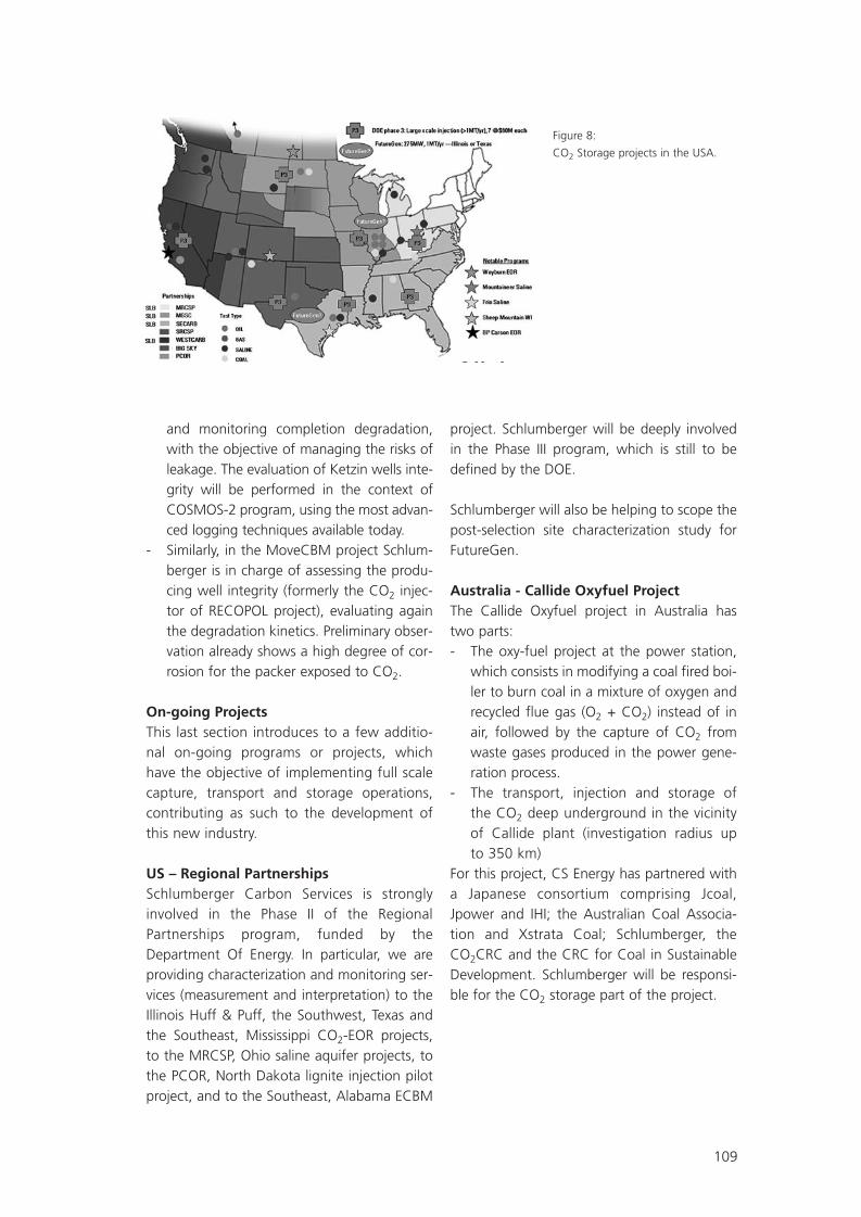
109
and monitoring completion degradation,with the objective of managing the risks ofleakage. The evaluation of Ketzin wells inte-grity will be performed in the context ofCOSMOS-2 program, using the most advan-ced logging techniques available today.
- Similarly, in the MoveCBM project Schlum-berger is in charge of assessing the produ-cing well integrity (formerly the CO2 injec-tor of RECOPOL project), evaluating againthe degradation kinetics. Preliminary obser-vation already shows a high degree of cor-rosion for the packer exposed to CO2.
On-going ProjectsThis last section introduces to a few additio-nal on-going programs or projects, whichhave the objective of implementing full scalecapture, transport and storage operations,contributing as such to the development ofthis new industry.
US – Regional PartnershipsSchlumberger Carbon Services is stronglyinvolved in the Phase II of the RegionalPartnerships program, funded by theDepartment Of Energy. In particular, we areproviding characterization and monitoring ser-vices (measurement and interpretation) to theIllinois Huff & Puff, the Southwest, Texas andthe Southeast, Mississippi CO2-EOR projects,to the MRCSP, Ohio saline aquifer projects, tothe PCOR, North Dakota lignite injection pilotproject, and to the Southeast, Alabama ECBM
project. Schlumberger will be deeply involvedin the Phase III program, which is still to bedefined by the DOE.
Schlumberger will also be helping to scope thepost-selection site characterization study forFutureGen.
Australia - Callide Oxyfuel ProjectThe Callide Oxyfuel project in Australia hastwo parts:- The oxy-fuel project at the power station,
which consists in modifying a coal fired boi-ler to burn coal in a mixture of oxygen andrecycled flue gas (O2 + CO2) instead of inair, followed by the capture of CO2 fromwaste gases produced in the power gene-ration process.
- The transport, injection and storage of the CO2 deep underground in the vicinityof Callide plant (investigation radius up to 350 km)
For this project, CS Energy has partnered witha Japanese consortium comprising Jcoal,Jpower and IHI; the Australian Coal Associa-tion and Xstrata Coal; Schlumberger, theCO2CRC and the CRC for Coal in SustainableDevelopment. Schlumberger will be responsi-ble for the CO2 storage part of the project.
Figure 8:
CO2 Storage projects in the USA.
SR09_FGS07.qxd 25.05.2007 14:43 Uhr Seite 109

110
Europe/Africa – Well Integrity study for the Hassi-Touareg CO2 Injection Field
In various parts of Algeria, the gas producedfrom the deepest horizons often contains CO2.The Gassi Touil integrated project (GTIP) hasindeed found that two of the gas fields have an8 to 10% CO2 content. For environmental rea-sons and, to a lesser extent, because of exportregulations, the partners have decided to sepa-rate and store the produced CO2 in one of thedepleted fields of the project: Hassi Touareg.
Schlumberger, in partnership with OXAND,conducted a comprehensive analysis to quanti-fy the potential leakage from existing wells,under a CO2 injection environment. Amongthe Hassi Touareg 14 wells, some were old pro-ducers, others were suspended and a fewplugged. The partners also wanted to assessthe possibility of converting existing wells toCO2 injectors, instead of drilling new wells.The results of this study, of which the work-flow is displayed below, have been presentedat the 2007 Schlumberger Well EvaluationConference in Algeria.
France – Integrated Capture and Storagedemonstrator in the Paris Basin
This project is still in a scoping phase and con-sists in realizing the first integrated CO2 captu-re and storage demonstrator onshore inEurope. The CO2 would result from a coal oxy-combustion pilot, on an existing vapor proces-sing plant, and would be directly injected onsi-te into the Trias formation of the Paris Basin. Schlumberger is currently positioned to be thestorage operator. The project involves the con-struction of 3 wells (1 injector and 2 monito-ring wells) and plans to inject 100 to 130 thou-sands tones of CO2 over 3 years. Highly sup-ported by public funds, it aims at providing aresearch platform for future national andEuropean projects, and a support to establishfuture European storage legislation onshore.
ConclusionFor now about 7 years, Schlumberger has beeninvolved in CO2 geological storage at differentlevels: providing services to industries or insti-tutes coordinating injection projects, as well asdeveloping technologies and services throughan internal R&D effort.
Figure 9: CS Energy Callide oxy-fuel project.
SR09_FGS07.qxd 25.05.2007 14:43 Uhr Seite 110

111
Carbon Capture and Storage can play a majorrole in mitigating climate change issues byreducing greenhouse gases emissions in theatmosphere. Schlumberger is actively contribu-ting to developing this new industry, by joiningmost of the research collaboration to overco-me current issues, and by participating to pilotprojects and preparing for an industrial deploy-ment of the technology.
Figure 9: CS Energy Callide oxy-fuel project.
SR09_FGS07.qxd 25.05.2007 14:43 Uhr Seite 111

112
Natural analogues studies using noble gases geochemistry
Studies of natural analogues can be used tounderstand long-term processes affecting CO2
in geological storage. Noble gases are useful inert tracers to monitorCO2 origin, migration, physical processes andquantify its behaviour in the subsurface.
We collected gas samples from natural CO2
reservoirs and surface seeps in French carbo-gaseous province: Sainte Marguerite seeps(Allier, France), Montmiral natural CO2 field(Drôme, France), and in the Colorado Plateau(Green River seeps (Utah), Springerville StJohns natural CO2 field (Arizona)).The preliminary results obtained provide strongevidence for a mantle-derived magmatic sour-ce for CO2 in the natural accumulations and inthe spring gases and are indicative of variousphysical processes affecting CO2 during itsmigration.
For example, natural CO2-degassing springsnear Sainte Marguerite, Allier, France show evi-dence of Rayleigh fractionation on argon,neon isotopes and elementary ratio of atmos-pheric-derived noble gases. This distillationprocess highlights rapid migration of CO2
toward the surface, consistent with small accu-mulation of radiogenic/nucleogenic isotopes.
The Helium concentrations range between0.28 and 8.22 ppmv, consistent with a magmadegassing at depth. Such low concentrationsimply that solubilization of CO2 in water occurs
at shallow depth, thus CO2 migration mainlyoccurred in the gaseous state.
Travertine-depositing springs and fossil traver-tine deposits are geological records that tracethe movement and discharge of CO2 and asso-ciated fluids to the Earth’s surface (Crossey etal., 2006). These deposits were observed onthe various natural analogues studied, and arecommonly located along faults.
Travertines samples were also collected toobtain information about the origin of CO2
carried by the water from which the travertinesdeposited, using the classification of Pentecost(2005). Selected travertines were analyzed forδ13C and δ18O by mass-spectrometry.
In certain cases, travertines can reflect deepCO2 leakages, or on the contrary underline thegood containment of the deep CO2 reservoir.
ReferencesCrossey L.J., Fischer T.P., Patchett P.J., KarlstromK.E., Hilton D.R., Newell D.L., Huntoon P., Rey-nolds A.C. and G.A.M. de Leeuw, 2006. Dissec-ted hydrologic system at the Grand Canyon:Interaction between deeply derived fluids andplateau aquifer waters in modern springs andtravertine. Geology, 34, 1, pp. 25-28.
Pentecost A., 2005. Travertine. Springer-Ver-lag, Tiergartenstrasse 17, D-69121 Heidelberg,Germany. Hardcover, 446 pp., 204
Jeandel E. (1, 2), Battani A. (1), Sarda P. (2), Emmanuel L. (3) , Tocqué E. (1)
(1) Institut Français du Pétrole, 1-4, av. de Bois Préau, 92852 Rueil-Malmaison Cedex, France
(2) Dept. Sciences de la Terre, bât. 504, 91405 Orsay cedex, France
(3) Laboratoire Biominéralisations et Paléoenvironnements – J.E. 2477, Univ. P. & M. Curie,
4 place Jussieu, 75252 Paris cedex 05
SR09_FGS07.qxd 25.05.2007 14:43 Uhr Seite 112
113
Experimental Characterization of Lavoux Limesfor the Geological Storage of CO2
Since 2005, the French National ResearchAgency supports several scientific projectsintended to select, validate and implement ageological site for CO2 storage in France. Thework presented in this paper is carried withinthe frame of the Geocarbone-lnjectivity projectaimed to study the suitability of a carbonatedeep saline aquifer located in the Par basin.
The injection of super critical CO2 through awell implies a radial two-phase low in the aqui-fer. As the geometry of the flow is radial, velo-cities will decrease with the distance to theinjection well and thus, different flow regimeswill be observed with the distance o the well.Near the injection well, flow velocities will behigh and the flow may reach the inertial regi-me. On the opposite, far from the injectionwell, velocities will be very low and capillaryforces may dominate the flow. Of course, inbetween, the classical Darcy regime will beobserved. Moreover, porosity and permeabilityheterogeneities in the aquifer may lead to flowinstabilities and then to a spatially heterogene-ous distribution of the CO2.
In addition, it is well known that CO2-brine-rock interactions may lead to two possiblereactions: i) partial dissolution of the originalcalcite and/or ii) precipitation of anhydrite. Inboth cases the pore structure of the aquiferwill be modified. Therefore, hydrodynamic pro-perties are highly coupled to the acidificationproduced by the CO2-saturated brine in theaquifer under storage conditions of pressureand temperature.
Several characterization experiments wereconducted on Lavoux limestone samples,which is a geological analog (i.e. same compo-sition) to the aquifer. Measured parameterswere porosity, permeability, inertia coefficient,Klinkenberg coefficient and relative permeabi-lities. Also, in order to evaluate the degree ofheterogeneity of the samples, tracer experi-ments were conducted and the results wereanalyzed by two different approaches: i) theclassical convection dispersion equation whichgives the dispersion coefficient and ii) the stra-tification factor approach which gives a quali-tative evaluation of the heterogeneity of thesample at the core scale. Finally, CT Scan ima-ges of samples were performed in order tovisualize the pore structure.
For each sample, the above characterizationwas done twice. Once in its original state andonce after a phase of CO2-brine-rock interac-tion. The interaction experiments were con-ducted under storage conditions and for diffe-rent duration periods.
Results allow to visualize the modification ofthe pore structure and to quantify the inducedmodification on the hydrodynamic propertiesof the limestone due to the CO2-brine-rockinteractions under storage conditions.
Kacem M. (1) , Radilla G. (1) , Lombard J.M. (2) and Fourar M. (1)
(1) Laboratoire d'Energetique et de Mécanique Théorique et Appliquée -Nancy Université, CNRS 2,
avenue de la Foret de HayeJ BP 160 54504 Vandoouvre CedexJ France
(2) Institut Francais du Pétrole -Petrophysics Department 1, Avenue de Bois Préau -92500 Rueil Malmaison, France
SR09_FGS07.qxd 25.05.2007 14:43 Uhr Seite 113

114
CO2-free Power Plant »Schwarze Pumpe«Vattenfall`s Oxyfuel Pilot Plant
Introduction - Electricity Generation Based on Fossil FuelsIn the year 2006, Vattenfall generated anamount of 165 TWh of electricity altogether,thereof 45% was based on fossil fuels. In thenorthern countries generation is mainly basedon nuclear power and renewables, while fossilfuels are predominantly used by the Germanpart of the Group (Vattenfall Europe).
A closer look on Vattenfall Europe’s powerplants shows that the generation capacity alto-gether is about 16.6 GW and 73% of it isbased on fossil fuels, mainly lignite. With aninstalled output of more than 11 GW at coal-fired power plants these days, VattenfallEurope is going to implement new projectswithin the next 4 years, among them a new
lignite-fired power unit in the Lausitz area andthree new hard coal-fired power units nearHamburg and in Berlin which will mean anincrease in capacity by 3,100 MW. In2011/2012 Vattenfall Europe’s total capacitybased on coal will come up to more than 14GW. Vattenfall Europe’s way of electricitygeneration is based on lignite and there areseveral reasons for this. The company is basedin the Lausitz area where large lignite resour-ces can be found that will last for at least anot-her 50 or 60 years, maybe even longer.Another reason of course is the price. The abili-ty to produce lignite at reasonable costs makesthe future price development for energy gene-ration quite calculable.
Kosel D.
Vattenfall Europe Generation AG & Co. KG
SR09_FGS07.qxd 25.05.2007 14:43 Uhr Seite 114

115
Having in mind that this is the basis for its elec-tricity generation in Germany, Vattenfall is wellaware of its responsibility regarding the deve-lopment of advanced and highly efficientgeneration processes and technologies forCO2-free power plants.
Reducing CO2 – Vattenfall`s Strategy forCO2-free Power PlantsThere are two ways to reduce CO2 emissionsfrom coal-fired power plants. One the onehand side you can increase the efficiency of theoverall process and on the other hand sidethere is the chance to implement some carboncapture and storage (CCS) technology.Increasing efficiency means that a plant emitsless CO2 per produced quantity unit of electri-city. Installing some CCS technology means toseparate the CO2 from the flue gas and avoidits emission into the atmosphere.
a) Increased EfficiencyOne example for reduced CO2 emissions viahighly efficient state-of-the-art lignite powerplant technology is the new project in Boxberg(Saxony). Boxberg is a power plant locationwhich can look back on a long tradition. From1970 to 1996, 12 lignite-fired power plantswith an output of 210 MW each were opera-ted here. However, these units have beendecommissioned. Since 1979, two 500 MWlignite-fired units have been run there andsince the year 2000 a 900 MW unit has beenoperated as well.
The new block will be a 675 MW unit, whichis under construction at the moment. With anefficiency factor of 43.3 per cent as well asmain steam temperatures of 600 degrees andreheat temperatures of 610 degrees, this unitwill meet the highest economical and technicalrequirements. A comparison between the 500MW units and the new 675 MW unit inBoxberg shows that using state-of-the-arttechnology will reduce specific CO2 emissionsby 25 %.
SR09_FGS07.qxd 25.05.2007 14:43 Uhr Seite 115

116
For the future Vattenfall sees two major waysto increase efficiency levels considerably. Thefirst one is to build water-steam cycles withsteam temperatures of around 700° C. Theother is the process of integrated lignite dry-ing. Applying all this, future net efficiency fac-tors of around 53 per cent will be achievable.Such efficiency factors would guarantee areduction of specific CO2 emissions by nearly40%, compared to a 500 MW unit in Boxberg.According to IEA`s clean coal centre, theworldwide average efficiency of coal-firedpower plants is lower than 32%. So an increa-se of efficiency could have a huge impact onthe reduction of CO2 emissions worldwide.Just implementing state-of-the-art technologycould reduce CO2 emissions of coal-basedelectricity generation by more than 25 %worldwide.
b) CCS TechnologiesIn a medium range perspective, there are threepossible technical options for large scalepower plants with implemented CCS.- Post-combustion capture: scrubbing out
the CO2 from the flue gas of a conventio-nal power station.
- Pre-combustion capture: gasifying the coaland separating the CO2 from the generatedfuel gas before the combustion process.
- Oxyfuel: combustion of the coal by usingpure oxygen.
Among the feasible technologies for CO2 freepower plants, Vattenfall is favouring the Oxyfuelprocess and there are a number of reasons topromote its development. Vattenfall considersOxyfuel as a process with a huge potential forincreasing efficiency, and the highest capabilityfor CO2 separation. Not less important to us isthe fact that an Oxyfuel power plant is based onthe conventional water steam cycle. Powerplant engineers already know the advantagesand the silver lining of this process and theOxyfuel process can be built up on this know-ledge. This allows a quite good estimationregarding investment and operating costs.
SR09_FGS07.qxd 25.05.2007 14:43 Uhr Seite 116

117
Vattenfall`s Oxyfuel Pilot PlantDuring the Oxyfuel process, coal is not combu-sted by use of the surrounding air, but withpure oxygen. A huge amount (a. 60-75%) ofthe flue gas is re-circulated into the combus-tion chamber. This re-circulation is necessaryfor controlling the combustion temperature toavoid exceeding thermal stress for the boilermaterials. By burning coal with pure oxygen, aCO2-rich flue gas stream is generated which isthen cleaned in the subsequent process steps.The flue gas is dedusted and desulphurised ina way, similar to that in the conventionalpower station process. Finally, the remainingwater content is condensed and separated, sothat a clean and dry flue gas with a maximumcontent of CO2 is available at the end of theprocess chain.
Vattenfall will erect and operate the firstOxyfuel plant worldwide, including the com-plete process chain from the air separation unitto the CO2 unit. The structure and the equip-ment of the plant consist of the following maincomponents. The first facility is the air separa-tion unit, followed by the boiler, the electrostatic precipitator, the flue gas desulphurisa-
tion unit, the flue gas condenser and the CO2
cleaning and liquefaction unit. All units areintegrated. There will be no turbine becauseoperating a turbine isn’t part of the test pro-gram for the Oxyfuel process. Process steamwill be produced and supplied to the full scalepower plant Schwarze Pumpe to support cer-tain systems there. The pilot plant will have athermal output of 30 MW and will produceabout 9 t of liquid CO2 per hour. The wholeplant makes an investment of more than 60million Euro necessary. After the start of ope-ration in 2008, several test programmes forthe entire plant are planned.
The boiler will be fired using different types offuel, dried lignite as well as hard coal. Testswith fuels of different quality will be run aswell. It is planned to vary burner registers andrecirculation. The focus will be on the combus-tion performance, ash qualities, flue gas com-position and radiant heat transfer in the com-bustion chamber, flame characteristics as wellas the corrosion potential in the chamber.Besides the boiler, there will be tests with othercomponents as well. So it is very important tocheck the interaction between the air separa-
SR09_FGS07.qxd 25.05.2007 14:43 Uhr Seite 117

118
tion unit and the boiler regarding the loadalternation mode. We require information onseparation rates of the electro static precipita-tor and of the flue gas desulphurisation plantat different levels of flue gas composition. Thetest operation will enable the determination ofthe entire plant’s CO2 recovery rate and theoperating performance of a whole powerplant so that the planning for a demonstrationplant can be started successfully.
OutlookSince 2005/2006 there have been test facilitiesof different power levels operating in Cottbusand Dresden. Smaller power levels shouldmake it possible to transfer important scientificfindings onto the pilot plant. The ADECOS-project at the university in Dresden is subsidi-sed by the German Department of Trade andIndustry. After a successful start of our pilotplant in Schwarze Pumpe, Vattenfall will erecta larger demonstration plant that is supposedto start operation in 2015. After demonstra-ting the Oxyfuel process successfully, it is plan-ned to erect a large power plant with an instal-led capacity of 1,000 MW based on theOxyfuel process.
ConclusionThere is still a lot to do to make the Oxyfuelprocess ready for use at large scale powerplants. Anyway, with the decision to build apilot plant Vattenfall made a first vital step inthe right direction, a first step to cope with thistask. The economic efficiency of CO2-freepower plants has not been proved yet and itwill definitely depend to a large amount on thesurrounding political conditions and the tech-nical development of components necessaryfor this process. Despite all questions that willstill have to be answered, Vattenfall is sure thatCO2-free power plant technology based onfossil fuels, and especially lignite, will prove itsfunctionality. In this process, all technicaloptions have to be used, including gasification,flue gas scrubbing and Oxyfuel.
SR09_FGS07.qxd 25.05.2007 14:43 Uhr Seite 118

119
SR09_FGS07.qxd 25.05.2007 14:43 Uhr Seite 119

120
Experimental studies on physical sorption processes and seal efficiency as related to the geological storage of CO2
IntroductionThe extraction of CO2 from flue gas of powerplants and other point sources with subsequentdeposition in appropriate geological formationsis presently considered an option that couldcontribute significantly to short and interme-diate term greenhouse gas emission reduction.During the past decade, numerous research pro-jects have investigated in great detail variousaspects of the geological storage of CO2.
Concerns about CO2 emission penalties andthe initiation of emission trading have triggeredefforts of large-scale CO2 emitters to exploreand secure geological storage options in antici-pation of a legal framework - which is still mis-sing. Mainstream R&D for CO2 storage present-ly focuses on saline aquifers which combinehigh storage capacities and high injectivities.Depleted oil and gas fields, if available, repre-sent interesting storage options with smallercapacities but short-term availability. All ofthese underground storage options, however,are presently economically interesting targetsfor intermediate storage of natural gas.
Carbon dioxide storage in unminable or unmi-ned coal has been under study for some time;taking advantage of the high specific gas sto-rage capacity of coals at low to moderate pres-sures. There is a common understanding thatthis storage option is feasible only in a syner-getic way in combination with coalbed metha-ne production.
The technical feasibility of CO2 injection intogeological formations under various conditions(offshore and onshore) has meanwhile beendemonstrated. Even before the launch of large-scale dedicated flagship projects such as theSleipner field, CO2 injection has been used - forother purposes though, and almost unnoticed -in enhanced oil recovery (EOR) over decades.
Research on geological storage of CO2 nowconcentrates on the long-term integrity of geo-logical storage systems, the assessment of risks,tolerances and potential intensities of leakage,and the design of monitoring procedures.Furthermore, the fate of CO2 in the subsurfaceand its impact on the geochemical, mineralogi-cal and rock-mechanical properties of storageformations has become a focus of recent rese-arch. Tackling these issues requires interdiscipli-nary skills very similar to those required inpetroleum and natural gas exploration. Basedon this background of expertise in the analysisof gas and petroleum-related processes in sedi-mentary basins, both on the experimental andthe modelling side, our institute has been enga-ged in research on various aspects of geologicalstorage of CO2 for nearly a decade.
RWTH/LEK research profileIn the context of exploration for petroleum,natural gas, coal and coalbed methane ourgroup has been actively involved in providingexperimental data on fluid generation andtransport processes in sedimentary basins
Krooss B. M. and Busch A.
Institute of Geology and Geochemistry of Petroleum and Coal (LEK), RWTH Aachen University, Lochnerstr. 4-20,
D-52056 Aachen, Germany, E-Mail: [email protected]; [email protected]
SR09_FGS07.qxd 25.05.2007 14:43 Uhr Seite 120

121
(GASCHNITZ et al., 1997; KROOSS andSCHAEFER, 1987; KROOSS, 1992; KROOSSand LEYTHAEUSER, 1988; KROOSS and LEY-THAEUSER, 1997; KROOSS et al., 1992;SCHLOEMER and KROOSS, 1997). Based onthis expertise experimental procedures havebeen modified in recent years and adapted tothe special requirements of research for CO2
storage in geological systems. Funding for thisresearch came initially from the two EU pro-jects, NASCENT [1] and RECOPOL[2].
The experimental approaches have been andare being used in a number of internationaland national follow-up projects listed in Table1. Among these, the CO2TRAP project in thecontext of the German GEOTECHNOLOGIENprogramme is presently our main activity inCO2 sequestration research. Selected resultsfrom the projects listed in Table 1will be pres-ented below.
Experimental methodsThe two main lines of experimental work followed at RWTH/LEK in the context of CO2
storage are: - characterisation of the efficiency of geolo-
gic seals and - high-pressure sorptive gas storage on coals.An overview of the experimental proceduresand methods is given in Table 2.
Seal efficiency of geologic formationsThe characterisation of seal efficiency and qua-lity is usually based on a combination of expe-rience from geological systems (natural analo-gues) and experimental evidence. Due to limi-tations in scale and representative elements ofvolume (REV) only caprock/seal processes rela-ting to the petrophysical properties of more orless homogeneous rock samples are amenableto laboratory measurements. Fluid flow pro-cesses controlled by large-scale fracturesystems are essentially unpredictable on a geo-
Table 1: Overview of past and ongoing projects on CO2 storage with participation of RWTH/LEK.
SR09_FGS07.qxd 25.05.2007 14:43 Uhr Seite 121

122
logic time scale. The occurrence of large-sizenatural gas reservoirs - even in tectonicallyactive zones - indicates, however, that (i)gases can be trapped in the subsurface effi-ciently over long geologic periods of time and(ii) in many instances seal efficiency is con-trolled by the petrophysical properties acces-sible by laboratory experiments. Figure 1shows a scheme of the triaxial flow cell usedfor the study of fluid transport processes infine-grained sedimentary rocks.
The transport processes studied with this expe-rimental set-up comprise pressure-driven volu-me flow (Darcy flow) of single- and two-phase(water-gas) systems and gas diffusion in water-saturated rocks.
Pressure-driven volume flow- Single phase flow tests are usually carried
out with water in a steady-state mode toassess the permeability coefficients of thefine-grained seal lithotypes (shales, siltsto-nes) and for water saturation of the con-ducting flow system. Permeability coeffi-cients down to the sub-nanodarcy range(<10-21 m2) can be determined with thisprocedure.
- Gas-breakthrough tests with differentgases (He, N2, CO2) have been extensivelyperformed to assess the capillary sealingefficiency of the water-saturated rocks andthe rate of gas flow after the capillary entrypressure has been exceeded. The experi-mental procedure has been described in
Table 2: Overview of experimental procedures used at RWTH/LEK in the research on CO2 storage in geological systems.
Figure 1: Triaxial fluid flow cell used for the study of fluid transport processes in fine-grained sedi-
mentary rocks (seal lithotypes). Sample size: diameter 28.5 mm, length: 5 – 25 mm.
SR09_FGS07.qxd 25.05.2007 14:43 Uhr Seite 122

123
several publications related to hydrocarbonseals and CO2 storage (HILDENBRAND etal., 2004; HILDENBRAND et al., 2002;SCHLOEMER and KROOSS, 2004; SCHLOE-MER and KROOSS, 1997).
Molecular diffusion- Diffusive transport of CO2 in water-satura-
ted rocks is measured by a procedure origi-nally developed for hydrocarbon gases andnitrogen (KROOSS and SCHAEFER, 1987;SCHLOEMER and KROOSS, 2004; ZHANGand KROOSS, 2001). Here the phase beha-viour and the chemical reactivity constitu-ted a major experimental challenge.Although molecular diffusion is not consi-
dered a relevant process for large-scale lea-kage of gases from reservoirs it constitutesa rate-controlling process in geochemicalreactions that may affect the mechanicaland petrophysical properties of seal layers.The nonsteady-state experimental procedu-re used in our laboratory also providesinformation on the gas storage capacity ofthe lithotype due to adsorption or, particu-larly in the case of CO2, chemical reactionswith the mineral matrix.
High-pressure gas sorption on coalsThe experimental methods for high-pressuregas sorption measurements on natural coalswere based on procedures originally developed
Figure 2: Schematic diagram of gas breakthrough experiments to
assess the capillary sealing efficiency and gas permeability (kgas)
after breakthrough for fine-grained sedimentary rocks.
Figure 3: Conceptual scheme of gas
breakthrough and imbibition process
during laboratory test.
SR09_FGS07.qxd 25.05.2007 14:43 Uhr Seite 123

124
for coalbed methane (CBM) studies. A schemeof the set-up is shown in Figure 5. The adapta-tion to CO2 measurements was not trivial dueto the fact that the experimental conditions(pressure, temperature) required were relative-ly close to the critical point of CO2 (30.98 °C,7.38 MPa). High-precision pressure and tem-perature measuring devices in combinationwith modern equations of state (EOS) (SPANand WAGNER, 1996) resulted in good repro-ducibility and inter-laboratory comparability asdemonstrated by round robin tests (GOOD-MAN et al., 2007; GOODMAN et al., 2004).
Results, achievements and perspectivesThe following chapters give a brief overview ofthe experimental results and achievements ofthe past and ongoing research projects.
NASCENTThe objective of the NASCENT (NaturalAnalogues for the Storage of CO2 in the Geo-logical Environment) project was the investiga-tion of geologic situations with natural occur-rences and different intensities of CO2 emis-sion in France, Germany, Greece, Hungary andItaly. Each of these locations was studied ingreat detail to analyse the conditions, effectsand processes related to long-term under-ground storage of CO2.
Within the NASCENT project, RWTH/LEK per-formed fundamental experimental laboratorywork to assess the sealing efficiency of caprock sequences overlying natural CO2 reservo-irs. The experiments comprised permeabilityand gas breakthrough tests for the assessmentof the capillary gas-sealing efficiency. Within
Figure 4: Scheme of diffusion experiments for CO2 in water-saturated sedimentary rocks with cumulative dif-
fusion curve measured on a Carboniferous coal sample from Poland (RECOPOL project).
Figure 5: Scheme of the manometric set-up for high-
pressure (up to 25 MPa) sorption experiments with pure
gases (CO2, N2, CH4) and gas mixtures.
SR09_FGS07.qxd 25.05.2007 14:43 Uhr Seite 124

125
this project the experimental procedure forCO2 diffusion measurements in water-satura-ted rocks was developed and first measure-ments were performed. The experimentalresults obtained during this project were sum-marised in several publications (HILDENBRANDet al., 2003; HILDENBRAND et al., 2004; HIL-DENBRAND et al., 2002).
Results of numerous gas breakthrough experi-ments were compiled in a mudrock databasetogether with other relevant petrophysicalparameters. These data were systematicallyevaluated for correlations. As an example, cor-relations between capillary breakthrough pres-sure and effective permeability for N2, CH4 andCO2 are shown in Figure 6. It is evident fromthis diagram that the capillary sealing efficien-cy of fine-grained rocks for CO2 tends to beslightly less than for other gases, probably dueto lower interfacial tension and/or higher wet-tability. Based on the experimental data, esti-mates can be made on the potential gas lossesafter the capillary entry pressure has beenexceeded. The experiments also indicate thatafter a decline in reservoir pressure re-imbibi-tion of water will lock up the conducting poresand gas leakage by pressure-driven volumeflow will come to a stop.
The capillary leakage concept and the experi-mental data have been implemented into asimple dynamic leakage model to estimatepotential gas leakage over geologic time.
The diffusion experiments with CO2 that wereinitiated in the NASCENT project were conti-nued on different sample sets in subsequentprojects (e.g. CASTOR) and are presentlyessential parts of the CO2TRAP and the »NRWcaprock« projects.
Experiments have shown that the CO2 storagecapacities of different shale and silt lithotypesvary by more than one order of magnitude.These findings have prompted us to conductmore detailed investigations into the mineralo-gical and chemical composition of these litho-types. Present results indicate that besides theirpetrophysical sealing properties, certain shalecaprocks possess a considerable storage capa-city for CO2 and may act as buffer systems. Theinterrelationship of capillary sealing, diffusivetransport, mineral reactions and changes ofmechanical properties is a challenging but alsohighly promising field for future research.
RECOPOLBetween 2001 and 2004 RWTH/LEK participa-ted in the EU-funded RECOPOL (Reduction of
Figure 6: Relationship between capillary breakthrough
pressure and effective permeability for N2, CH4 and CO2
in fine-grained (shale, siltstone) sedimentary rocks.
SR09_FGS07.qxd 25.05.2007 14:43 Uhr Seite 125

126
CO2 Emissions by means of CO2 storage in theSilesian coal Basin of Poland) project co-ordi-nated by the Netherlands Institute of AppliedGeosciences-National Geological Survey (NITG-TNO). This project represented the first onsho-re field demonstration test for CO2 injection inEurope. In the Upper Silesian Basin in Poland,south of Katowice, CO2 was injected into coalseams by means of a 1200 m deep well whilegas was produced from an existing adjacentCBM production well. The field test was targe-ted at an enhancement of coalbed methaneproduction (ECBM) by CO2-injection and it wasaccompanied by laboratory experiments to elu-cidate the interaction of CO2 and methanewith coals under in situ conditions of pressure,temperature and moisture content.
Within the RECOPOL project extensive series ofhigh-pressure sorption experiments with indivi-dual gases (CO2,CH4) and gas mixtures(CO2/CH4) were performed by RWTH/LEK oncoals ranging in rank from 0.25 to 1.69 % VRr.The measurements were performed with dryand moisture-equilibrated coals of variousgrain sizes (<63 µm to about 3000 µm), at dif-ferent temperatures (22, 32, and 45°C) andpressures up to 23 MPa. This provided an exten-sive data base of thermodynamic parameterswhich was complemented by detailed investiga-tions on the kinetics of sorption and desorptionprocesses. Results of these studies have beenpublished by (BUSCH et al., 2004; BUSCH et al.,2006; BUSCH et al., 2003; MAZUMDER et al.,2006; SIEMONS and BUSCH, 2007)
The main results of the RECOPOL laboratorystudies can be summarised as follows:- high-pressure CH4 and in particular (super-
critical) CO2 excess sorption isotherms oncoals exhibit a distinct maximum in the 8 –10 MPa pressure range and decline at hig-her pressures; this phenomenon is attribu-ted to the increase in relative volume ofthe adsorbed phase and to swelling of thecoal matrix
- a 2:1 ratio of CO2 vs. CH4 sorption capaci-ty is only an approximation; observed ratiosrange from 1.3 – 3
- in contrast to common expectations, CO2 isnot always preferentially sorbed on coals inexperiments with CO2/CH4 mixtures; prefe-rential adsorption of CH4, when observed,occurs however, only in the lower pressurerange (up to about 8 MPa); the coal pro-perties controlling selective sorption of CH4
or CO2 are not yet known.- kinetic studies on different coals reveal
unambiguously that CO2 exhibits consider-ably higher sorption and desorption ratesthan methane; the mathematical descrip-tion of the gas sorption kinetics on coalsrequires the assumption of at least two setsof kinetic parameters; the sorption processin coal can be subdivided into a fast and aslow step which may be attributed to diffu-sive transport in the macro- and mesopo-rous and in the microporous system of thecoal matrix, respectively
While the RECOPOL project has providedenhanced insight into the mechanism and pro-cesses of the interaction of CH4, CO2 and theirmixtures with coals, the field test revealed sub-stantial problems associated with the low per-meability and injectivity of deeply buriedCentral European Carboniferous coal seams.
This experience gave rise to the idea of lookingfor targets with a better accessibility of coals forgas injection. Such situations exist in the dama-ge zones of active and abandoned coal mines.In view of the decline of coal mining activities inGermany, the investigation of excavationdamage zones of abandoned coal mines forsorptive CO2 storage was proposed within theGerman GEOTECHNOLOGIEN programme.
GEOTECHNOLOGIEN (CO2TRAP)The GEOTECHNOLOGIEN R&D programme isjointly funded by the German Ministry ofEducation and Technology (BMBF) and theGerman Research Foundation (DFG). Amongsome 10 different projects on different aspectsof CO2 storage the project CO2TRAP (Develop-ment and Evaluation of Innovative Strategiesfor Sequestration and Permanent Immobili-sation of CO2 in Geological Formations) com-
SR09_FGS07.qxd 25.05.2007 14:43 Uhr Seite 126

127
prises three research groups at RWTH AachenUniversity and two groups at the Universitiesof Stuttgart and Bayreuth, respectively. HereRWTH/LEK is involved in the evaluation of theconcepts of using abandoned coal mines forpermanent CO2 storage and in the develop-ment and application of methods for the cha-racterisation of caprock sealing efficiency.
Sorptive CO2 storage in excavation dama-ge zones of abandoned coal minesWhile abandoned coal mines offer the advan-tage of higher permeability/injectivity in com-bination with considerable amounts of residu-al coal, two main problems are associated withthis storage option: (i) the accessibility of theresidual coal (depending on the extension andgeometry of the damage zone in relation tounmined coal) and (ii) the effects of the miningactivities on the integrity of the overlying seals.A reliable assessment of this risk factor, especi-ally for mines at depth < 500 m needs to beperformed prior to injecting flue gas or CO2.Sorptive CO2 storage is assumed to significant-ly reduce this likelihood and intensity of leaka-ge because most CO2 is transferred to the sor-bed (solid) state and cannot migrate from thedeposit to the surface as long as pressure andtemperature remain constant in the reservoir.Figure 7 summarises the concepts and strate-gies presently under consideration in this pro-ject. The accessible residual coal volume con-stitutes one of the main uncertainty factors.
While this project was initially focused on thesorption capacity of the residual coal (whichcan amount to 75% of the mined coal) theunexpectedly high CO2 storage capacity of cer-tain shales has introduced a new perspectiveinto this part of the project. Experimental workis under way in the »seal characterisation« sec-tion of the CO2TRAP project to explore thepetrophysical, mineralogical and chemical pro-perties of shales in the target areas. Dependingon their accessibility and composition the sha-les may be capable of immobilising additionalamounts of CO2.
Various scenarios have been investigatedbased on the presently available experimentaldata on storage capacity and selectivity ofsorption processes. These comprise low-pres-sure injection, followed by pressure increasedue to flooding of the mine or, alternatively,injection at hydrostatic pressure after completeflooding. The option of direct injection of fluegas is also under consideration because itwould reduce costs for capturing CO2.Although CO2 is selectively sorbed from aN2/CO2 the efficiency of this process needs tobe explored in more detail (BUSCH et al.,2007a; BUSCH et al., 2007b; SIEMONS andBUSCH, 2007).
NRW caprock study (WestLB)Within this PhD project, RWTH/LEK is involvedin the characterisation of cap rocks. Thesemeasurements comprise gas breakthrough and
Figure 7: CO2 storage concepts and strategies for
abandoned coal mines.
SR09_FGS07.qxd 25.05.2007 14:43 Uhr Seite 127

128
diffusion tests on sample plugs as well as sorp-tion experiments on powdered samples.Additionally, mineralogical investigations aswell as numerical simulations will be perfor-med. The aim of this study is to provide gene-ric information on seal lithologies and identifypotential cap rocks in North Rhine Westphalia(W Germany) for the geological storage of CO2.
MOVECBMThe MOVECBM project is a follow-up of theRECOPOL project aiming at the developmentof monitoring and verification schemes forlong-term reliable and safe storage of CO2 incoal seams. The role of RWTH/LEK within thisproject is appraisal of cap rock integrity abovecoal seams used for CO2 storage. A conceptu-al approach is considered here, using a largedata base on cap rock properties to predict thesealing efficiency of certain cap rocks.Furthermore, geochemical alterations (mineraltransformations) along with petrophysicalchanges of cap rocks samples due to the inter-action with CO2 will be investigated by usingthe triaxial flow-through cells at LEK.
ConclusionThrough its collaboration in various projects onCO2 storage in geological systems RWTH/LEKhas acquired expertise in the experimental inve-stigation of a wide scope of processes related totransport, sorption thermodynamics and kine-tics of gases in sedimentary systems. The groupis strongly integrated into an international net-work of research groups in Australia, USA,China, Japan and many European countries.
ReferencesBusch A., Gensterblum Y., Krooss B., and LittkeR. (2004) Methane and carbon dioxide adsorp-tion–diffusion experiments on coal: upscalingand modeling. International Journal of CoalGeology 60, 151-168.
Busch A., Gensterblum Y., and Krooss B. M.(2007a) High-pressure sorption of nitrogen,carbon dioxide and their mixtures on ArgonnePremium Coals. Energy and Fuels in press.
Busch A., Gensterblum Y., Krooss B. M., andSiemons N. (2006) Investigation of High-Pressure Selective Adsorption/DesorptionBehaviour of CO2 and CH4 on Coals: AnExperimental Study. International Journal ofCoal Geology 66, 53-68.
Busch A., Kempka T., Waschbüsch M.,Fernández-Steeger T., Schlüter R., and KroossB. M. (2007b) CO2 storage in abandoned coalmines. In Carbon Dioxide Sequestration inGeological Media - State of the Art. Specialpublication of the American Association ofPetroleum Geologists (in press).
Busch A., Krooss B. M., Gensterblum Y., vanBergen F., and Pagnier H. J. M. (2003) High-pressure adsorption of methane, carbon dioxi-de and their mixtures on coals with a specialfocus on the preferential sorption behaviour.Presented at Geofluids IV, May 12-16, Utrecht.,J. Geochem. Expl. 78-79, 671-674.
Gaschnitz R., Krooss B. M., and Littke R. (1997)Coalbed methane; adsorptive gas storagecapacity of coal seams in the Upper Car-boniferous of the Ruhr Basin, Germany. AAPGEastern Section and the Society for OrganicPetrology joint meeting 81(9), 1551-1552.
Goodman A. L., Busch A., Bustin R. M.,Chikatamarla L., Day S., Duffy G. J., FitzgeraldJ. E., Gasem K. A. M., Gensterblum Y., HartmanC., Jing C., Krooss B. M., Mohammed S., PrattT., Robinson J., R. L., Romanova V., Sakurovs R.,Schroeder K., and White C. M. (2007) Inter-laboratory comparison II: CO2 isotherms mea-sured on moisture-equilibrated Argonne pre-mium coals at 55 °C and up to 15 MPa.International Journal of Coal Geology in press.
Goodman A. L., Busch A., Duffy G. J.,Fitzgerald J. E., Gasem K. A. M., GensterblumY., Krooss B. M., Levy J., Ozdemir E., Pan Z.,Robinson J., R. L., Schroeder K., SudibandriyoM., and White C. M. (2004) An Inter-laborato-ry Comparison of CO2 Isotherms Measured onArgonne Premium Coal Samples. Energy &Fuels 18(4), 1175-1182.
SR09_FGS07.qxd 25.05.2007 14:43 Uhr Seite 128

129
Hildenbrand A., Krooss B. M., Schlömer S.,and Littke R. (2003) Dynamic gas leakagethrough fine-grained seal lithologies. EAGEConference 8.-11.September 2003: Fault andTop Seals. What do we know and where dowe go?, O-15, 1-10.
Hildenbrand A., Schloemer S., Krooss B., andLittke R. (2004) Gas breakthrough experimentson pelitic rocks: comparative study with N2,CO2 and CH4. Geofluids 4, 61-80.
Hildenbrand A., Schlömer S., and Krooss B. M.(2002) Gas breakthrough experiments on fine-grained sedimentary rocks. Geofluids 2, 3-23.
Krooss B. and Schaefer R. G. (1987) Experimen-tal measurements of the diffusion parametersof light hydrocarbons in water-saturated sedi-mentary rocks: I. A new experimental procedu-re. Organic Geochemistry 11(2), 193-199.
Krooss B. M. (1992) Diffusive losses of hydro-carbons through cap rock. Experimental stu-dies and theoretical considerations. Erdoel &Kohle - Erdgas - Petrochemie/HydrocarbonTechnology 45, 387-396.
Krooss B. M. and Leythaeuser D. (1988)Experimental measurements of the diffusionparameters of light hydrocarbons in water-saturated sedimentary rocks: II. Results andgeochemical significance. Organic Geochemis-try 12(2), 91-108.
Krooss B. M. and Leythaeuser D. (1997)Diffusion of methane and ethane through thereservoir cap rock; implications for the timingand duration of catagenesis; discussion. AAPGBulletin 81(1), 155-161.
Krooss B. M., Leythaeuser D., and Schaefer R.G. (1992) The quantification of diffusivehydrocarbon losses through cap rocks ofnatural gas reservoirs - a reevaluation. AAPGBulletin 76(3), 403-406.
Mazumder S., van Hemert P., Busch A., WolfK.-H. A. A., and Tejera-Cuesta P. (2006) Fluegas and pure CO2 sorption properties of coal:A comparative study. International Journal ofCoal Geology 67, 267-279.
Schloemer S. and Krooss B. (2004) Moleculartransport of methane, ethane and nitrogenand the influence of diffusion on the chemicaland isotopic composition of natural gas accu-mulations. Geofluids 4(1), 81-108.
Schloemer S. and Krooss B. M. (1997) Experi-mental characterisation of the hydrocarbonsealing efficiency of cap rocks. Marine andPetroleum Geology 14(5), 565-580.
Siemons N. and Busch A. (2007) Measurementand Interpretation of Supercritical CO2 Adsorp-tion on Various Coals. International Journal ofCoal Geology 69, 229-242.
Span R. and Wagner W. (1996) A new equa-tion of state for carbondioxide covering thefluid region from the triple-point temperatureto 1100 K at pressures up to 800 MPa.Journal of Physical and Chemical ReferenceData 25.(6), 1509-1596.
Zhang T. and Krooss B. M. (2001) Experimentalinvestigation on the carbon isotope fractiona-tion of methane during gas migration by diffu-sion through sedimentary rocks at elevatedtemperature and pressure. Geochimica etCosmochimica Acta 65(16), 2723-2742.
SR09_FGS07.qxd 25.05.2007 14:43 Uhr Seite 129

130
Isotope-sensitive CO2 analysis and CH4detection by NIR diode laser absorption spectroscopy (DLAS) for monitoring at theKetzin carbon dioxide storage site
The steep increase of carbon dioxide emissionshas accelerated the greenhouse effect. Toantagonize this process several methods havebeen considered to reduce the CO2 concentra-tion in the atmosphere. The capture of CO2
and its storage in the underground (sequestra-tion) is a promising strategy, which requiressophisticated techniques to monitor possibleleakages at the storage site. As an importantEuropean reference CO2 storage site, theKetzin saline aquifer near Potsdam, Germany,is under intense investigation. Both, the rese-arch of CO2 and methane within the naturalgas reservoir provides valuable information.The determination of the isotopic signature ofcarbon dioxide (12C16O2,
13C16O2 and 12C18O16O) isof great interest about the CO2 source and theevaluation of underground gas transportpaths. The CH4 monitoring can lead to impor-tant information about displacement reactionsand its influence as a greenhouse gas.
Methane and the main three isotopologues ofcarbon dioxide can be measured by near-infra-red (NIR) absorption spectroscopy with tunablediode lasers in the spectral range around 1.6µm. A tunable diode laser absorption spectro-meter (DLAS) using an external cavity diodelaser and a Herriott-type multipass cell hasbeen developed to detect simultaneously theovertone bands of several gases. The measure-ment technique is based on wavelengthmodulation spectroscopy with electronically
balanced receiving. In the selected spectralarea there is no interference with water vapourand no cross-sensitivities towards other gases. In a national BMBF (German Federal Ministryof Education and Research) priority program aflexible and compact fiber-optic diode laserabsorption spectrometer suitable for field cam-paigns (field-DLAS) has been designed. Thenew experimental setup with a distributedfeedback (DFB) diode laser realizes the highisotopic resolution of carbon dioxide and thesimultaneous detection of methane at theKetzin storage site.
To evaluate the spectrometer, certified gassamples were filled into the multipass cell upto a total pressure of 50 mbar. The overallexperimental precision of the spectrometerwas tested by iterative runs, long-time measu-rements and calibration plots. Limits of detec-tion (LOD) in the low ppm range for each spe-cies were obtained. The high performances ofthe spectrometers make the detection of furt-her gases possible, e.g. the isotopic resolutionof carbon monoxide. Gas samples withdrawnat the storage site were characterized.
In cooperation with our partners in Florence(Italy) volcanic gases were measured in a fieldcampaign (May 2007).
Lau S., Salffner K., Löhmannsröben H.-G.
Institute of Chemistry, Physical Chemistry, University of Potsdam, Karl-Liebknecht-Str. 24-25, 14476 Potsdam-Golm,
Germany, E-Mail: [email protected], Fon: +49-331-9775176
SR09_FGS07.qxd 25.05.2007 14:43 Uhr Seite 130

131
Recent Development for long term modeling of CO2 storage
IntroductionFollowing the active R&D program initiated byANR, several teams are currently actively invol-ved in modeling CO2 geological storages withdifferent focus of interest in time (injection orstorage period) and space (near well bore, fullfield, geosphere). Therefore, different tools aredeveloped and used depending on the bak-kground of the modeling team (nuclear wastedisposal, hydrogeology, oil&gas). This papersummarizes the recent developments of theseteams and focuses on application to field scalerather than mechanistic modeling of the diffe-rent processes involved.
ModelsMost teams develop in part or fully their mode-ling tools. Thus, model development rangesfrom add-on to an existing tool such asTOUGHREACT (Xu and Pruess, 2001) , Cast3M(Le Potier, 1998 and Genty, 2000) up to deve-lopment of dedicated tools such as COORES(Le Gallo et al 2006 and Trenty et al, 2006) orHYTEC (van der lee et al., 2002, 2003).The code uses different numerical approachesbased upon finite volume (HYTEC, COORES,TOUGHREACT) or Mixed-Hybrid Finite Element(Cast3M) to solve the flow governing equa-tions in 3-D. However, differences exist bet-ween the codes regarding multiphase flows(most of them are only 2 phase) and reactivetransport (only one does not model it).
The coupling approaches between geochemi-cal and flow equations are different in everycodes (HYTEC, COORES, TOUGHREACT) whichrely on different geochemical modules. Allgeochemical modules integrate kinetic ratelaws but different level of development existsregarding reactive surface modeling in precipi-tation/dissolution reaction or high ionic strengthsolution model (Debye-Hückel vs. Pitzermodel). The feed back of mineral alterationson flow is mainly focus toward permeabilitychanges but other changes in flow parametersare computed for diffusion flux in HYTEC(Lagneau, 2000) and capillary pressure (COO-RES, TOUGHREACT).
Most of the codes assume compressible multi-phase flow and a few of them currently accountfor hysteresis of relative permeability. Most ofthe available tools account for thermal effects.
The geomechanical impacts are mainly hand-led through external coupling with dedicatedgeomechanical software with various couplingalgorithm. The main focus of the modelingteam is not yet on geomechanical interactionsbut rather on geochemical interactions eventhough work is currently underway in variousANR projects e.g. Geocarbon Injectivity,Geocarbon Integrity.
Le Gallo Y. (1), Trenty L. (1), Lagneau V. (2), Audigane P. (3), Bildstein O. (4), Mugler C. (5), Mugler E. (5)
(1) Reservoir Enginneering dept., Institut Français du Pétrole (IFP), 1&4 ave. Bois Préau,
92852 Rueil Malmaison Cédex, E-Mail: [email protected]
(2) Centre de Géosciences, École des Mines de Paris, 77305 Fontainebleau Cédex, E-Mail: [email protected]
(3) BRGM 3 ave. Claude Guillemin, BP 36009, 45060 ORLEANS Cédex 2, E-Mail: [email protected]
(4) DTN/SMTM/LMTE , CEA, Bat. 307, 13108 St Paul-lez-Durance, E-Mail: [email protected]
(5) Laboratoire des Sciences du Climat et de l’Environnement (LSCE/IPSL), CEA-CNRS-UVSQ, Orme des Merisiers,
91191 Gif-sur-Yvette Cédex, E-Mail: [email protected]
SR09_FGS07.qxd 25.05.2007 14:43 Uhr Seite 131

132
To handle the necessary coupling, softwareplatforms such as ALLIANCE which was origi-nally developed by the CEA, ANDRA and EDFto perform calculations of the long term evo-lution of radioactive waste disposal or ICAR-RE which is currently developed by IFP for oilindustry calculations connecting third partysoftware (reservoir and geosciences models)are started to be applied to CO2 storagemodeling.Besides featuring the implementation of dif-ferent existing (stand-alone) codes (compo-nents), the platform main advantage is toprovide a unified set of data, multi-domaincomputation, and coupling between somecomponents (e.g. flow, mass and heat trans-port, geochemistry).
ApplicationsThe modeling teams are focused on differentmodeling problems ranging from well scale tofull field simulations and from injection periodto storage life. This paper does not intend tothoroughly consider the various applications ofthe modeling tools to CO2 geological storagebut rather focus on key applications selectedby the various contributing teams.
Well scale applicationA simplified two-phase flow module has beendeveloped for HYTEC to investigate the pro-cesses in the near-field of an injection wellduring the early phase of injection, using a 1D-radial geometry. The fluid-rock interactions arecomplex: they are controlled by rapidly chan-ging saturation states (progression of the gasfront). The progression of reacted water and ofthe desaturation front defines a moving reac-tion zone (). The fast flow in the vicinity of thewell, and the dilution of the velocity at largerdistances from the well (radial propagation),leads to a decreasing propagation velocity ofthe reacting zone and its spreading out in timeand space. Accordingly, slower reactions beco-me important, causing a spatial zonation ofthe precipitates. Simultaneously, the solutecomposition is strongly modified along theflow path since all the previous reactions closerto the well alter the solution composition.Hence, the hydrodynamic and chemical pro-cesses are strongly coupled and simple reac-tion path simulations fail to describe the com-petition between kinetics of reactions andhydrodynamics.
Figure 1: Schematic view of the reacting zone in the well injection simulation: reac-
tions are bounded by the arrival of disequilibriated water (gas dissolution, previous
mineral reactions) and the final disappearance of water (pressure drive followed by
vaporization in the dry injected gas).
SR09_FGS07.qxd 25.05.2007 14:43 Uhr Seite 132

133
Aquifer hydrodynamics and upscalingAs large volume of CO2 should be injected andthe expected plume lateral scale, kilometricscale, it is probable that permeability willdisplay spatial variability due to rock heteroge-neity. Several numerical studies showed thatlarge scale heterogeneities (facies heterogenei-ties) have a significant impact on the behaviourof the injected carbon dioxide (Johnson, 2001)(Flett, 2006). Indeed, heterogeneities induce preferentialflow-paths for the gas-like CO2 plume which ispushed by the injection velocity field and sub-mitted to strong buoyancy forces. It results ina lateral spreading of the CO2 plume which inturn increases the contact surface between theplume and the host formation. Moreover, Kumar et al. (2005) showed thathorizontal to vertical permeability ratio has asignificant impact on gas migration. These pro-cesses affect CO2 dissolution in brine and car-bon mineralization (Kumar et al, 2005). Theintrinsic permeability value and the type ofrelative permeability curves are also veryimportant (Doughty, 2004). At the plume lateral scale, the numerical repre-sentation of small scale geological heteroge-neities is out of reach and one must upscalethe storage model. This is a classical problem inpetroleum reservoir engineering. One of themain processes which have to be upscaled isthe plume paths dispersion through permeableflow-paths resulting in a global spreading in alldirections. Consequently, one of the main modellingobjective is to derive for large scale modelseffective permeability and macro dispersiontensors. This problem has been studied bynumerous authors in several domains: inhydrology (Gelhar, 1993), hydrogeology(Sahimi, 1995) and oil reservoir engineering(Langlo, 1994, Christie, 1996).The case of CO2 migration in an heterogene-ous porous media is quite more difficult: flowis non stationary, equations describing flowand transport are hardly non linear, several for-ces play an important part in the CO2 migra-tion such as those due to gravity, capillary pres-sure, CO2 dissolution is important... The
impact of heterogeneities on these processesand the way to upscale them has been tackleonly recently (Panfilov and Floriat, 2004).An upscaling methodology and initial results ofan assessment of the impact of host-rockheterogeneity on CO2 plume migration is pres-ented. The CO2 injection in the porous mediais simulated with an incompressible two-phaseflow model. As a detailed characterization ofthe geological formation is too difficult toobtain, the impact of aquifer heterogeneitieson the CO2 plume migration is assessed in theframework of stochastic modelling throughMonte Carlo simulations and ensemble avera-ging. The stochastic approach provides a stati-stical description of the plume migration interms of means and variances. 2-D grids simu-late aquifer vertical sections with an injectionpoint located at the bottom of the aquifer. Inthese first simulations, we neglected capillarypressure forces and CO2 dissolution in water.
First, simulations of CO2 migration in a homo-geneous aquifer allowed to characterize theinfluence of the intrinsic permeability value onthe plume migration, and in particular on itsspreading. If the permeability is very low, buoy-ancy effects are negligible around the injectionpoint and the bubble migration is piloted bythe injection rate: it grows radially, accordingto the Buckley-Leverett theory. On the contra-ry, if the permeability is high, buoyancy effectsbecome rapidly predominant, and plumemigration becomes essentially vertical. In allcases, far enough from the injection well,migration bubble is buoyancy driven (Muglerand Mouche, 2006). These two behaviours arestill present in the case of a heterogeneousaquifer: if the intrinsic permeability is low(injection driven case), the plume first spreadsradially through permeable flow-paths andreaches rapidly the lateral limits. In a secondstep, it migrates in the low permeable strata.On the contrary, if the intrinsic permeability ishigh enough (buoyancy driven case) the plumerises vertically through strata distribution in aquasi 1D migration (Mugler and Mouche,2006). These first simulations showed theimportance of the intrinsic permeability: in the
SR09_FGS07.qxd 25.05.2007 14:43 Uhr Seite 133

134
buoyancy driven case, the plume should occu-py the top of the aquifer only; at the contrary,in the injection driven case, the plume shouldinvade all the aquifer.
Second, Monte Carlo simulations of injectionof CO2 were performed in a 2D heterogeneousaquifer. The host-formation intrinsic permeabi-lity is assume to be a lognormal anisotropicrandom process. The domain extent is 20 λH
wide and 27 λV high, where λH and λV are thehorizontal and vertical correlation lengths,respectively, with λH/λV=10 and λV=1 m. Thelog10 permeability covariance is assumed tobe exponential, with a mean log10 intrinsicpermeability <log10K> equal to 12.3 and alog10 standard deviation σ equal to one. Twohundreds realizations of permeability fieldwere generated and these fields were used asinput to the two phase flow model. The dura-tion of each simulation was about two to threeCPU hours. Figure 2 shows various CO2 plumedistributions obtained with 5 different realiza-tions of the permeability field, after four daysof injection. By comparison, (a) gives the CO2
plume obtained with a homogeneous permea-bility K equal to 5 x 10-13 m2 (log10K= 12.3).These various patterns illustrate the influenceof heterogeneities on the behaviour of CO2
which rises upwards and spreads through per-meable flow-paths.
The different types of spreading obtained fromMonte Carlo simulations may be quantified bya moment analysis of the CO2 saturation spa-tial distribution (Gelhar, 1993). In the simplecase where the solute transport equation is 1-D convection-dispersion type, the time deriva-tive of the first spatial moment is equal to theflow velocity and the dispersion coefficient isproportional to the time rate of change of thespatial second moment (Gelhar, 1993). In ourcase, these relations are no more valid becau-se of the presence of non linearities and gravi-ty forces. For each Monte Carlo simulation, thehorizontal and vertical second spatial momentsaround the center of mass are calculated . Thetime evolution of these 200 moments allow toquantify the CO2 plume dispersion (see Figure3). The challenge is now to determine a homo-geneous media equivalent to the heterogene-ous one giving horizontal and vertical secondspatial moments quite identical to themoments averaged over the 200 Monte Carlo simulations.
It is well-known that heterogeneities which arevery likely to be present in formations ofporous media will have a significant effect onthe migration of injected CO2. Low permeabi-lity zones (for example mud, shales, ...) slowdown the upward migration of CO2 and helpits lateral distribution. Mean permeability valueis very important. For low values, the meanmigration is radial and macro dispersion seems
Figure 2: CO2 saturation distributions after 4 days of injection, with <log10K> = -12.3
and (a) σ = 0 (homogeneous case) and (b)-(f) σ =1 (heterogeneous cases).
SR09_FGS07.qxd 25.05.2007 14:43 Uhr Seite 134

135
to be similar to a single phase injection in amultiphase reservoir: the plume exhibits fin-gers moving radially in permeable flow paths.For high values, buoyancy is predominant: themean migration is vertical and macro disper-sion should occur only vertically. One of the final objectives of this work is todefine equivalent migration parameters forlarge scale simulations, corresponding to thosethat would be obtained for an equivalenthomogeneous media. Monte Carlo simulationsand a moment analysis of CO2 saturationdistribution will allow us to define equivalentmigration parameters for volumes of rock andsediment with sizes comparable to grid blocksused in large scale flow simulations (about tensto hundreds of meters). These scaled-up para-meters will be used as input to a large scaleflow model of CO2 injection, with the aim ofassessing the importance of accounting for theeffects of rock and sediment heterogeneity onthe behavior of injected supercritical CO2.
Gas storage and geochemical impactThe K12-B field is a depleted methane reser-voir located in the North Sea produced by Gazde France Netherlands since the 80’s. This fieldis one of the four sites of the CASTOR projectfunded by the European Commission within the6th European Framework. Within the CASTORproject, a numerical modeling study on hydro-dynamic and geochemical impact of the CO2
injection at K12-B was developed (Audigane etal., 2007). Due to the complexity of the multi-phase system (CO2 and CH4 gas mixture anddissolution coupled with fluid rock geochemicalinteraction), a complete coupled simulation ofthe CO2 injection into a methane gas field esti-mating at the same time the geochemical reac-tivity was divided in two separate simulationsusing (i) TOUGHREACT to estimate mineraltrapping (case A) and (ii) using TOUGH2/EOS7Cto estimate structural and solubility trapping(case B). The injection rate is chosen at 10 kg/swhile production rate has been chosen arbitraryten times smaller than injection rate at 1 kg/s foreach producer K12-B1 and K12-B5 in order tolimit the CO2 breakthrough time.
Figure 3: Evolution versus time of the
second spatial moments of the 200
Monte Carlo simulations: (a) horizontal
second spatial moments, (b) vertical
second spatial moments.
SR09_FGS07.qxd 25.05.2007 14:43 Uhr Seite 135

136
This simulation was carried out assuming thatthe storage of large quantities of CO2 was aprimary objective. Results show that mineraltrapping plays a minor role in terms of CO2
storage. As the reservoir contained initially13% of CO2 in the gas phase, the geochemi-cal system is equilibrated between fluid androck minerals. Therefore, injection of CO2 willnot induce large modification of the system.As illustrated by Figure 4a for the pH field after10 years of injection simulated values rangefrom 4.40 to 4.58 with slight variations distin-guished in for regions through the reservoir.
The simulation for Case B (Figure 4b) shows arelatively short CO2 arrival time in the produ-cers (60 days and one year) and a linear incre-ase of reservoir pressure between 47 bar to104 bar. Though, these breakthrough timesare relatively short and therefore the predictionof the enhanced gas recovery efficiency is rat-her poor, the capacity of CO2 storage remainsgood as only 20 % of the injected mass of CO2
is produced from the reservoir.
Reactive transport modeling of the CO2 injec-tion into saline aquifers is well addressed whenusing TOUGHREACT. Nevertheless, when con-sidering gas mixtures (impurities or gas reser-voir), some simplifications are to be made.Either considering a gas phase constitutedwith pure CO2 with geochemical fluid rockinteractions, or using a EOS module able tohandle the gas mixtures (CO2, CH4 S2H…) butneglecting induced geochemical reactivity. The
present case study is a perfect illustration ofsuch limitation as two separate simulationshad to be performed to complete a full studyof the structural dissolution and mineral trap-ping occurring during the injection of CO2 intothe depleted methane reservoir.
Aquifer storage and geochemical impactA 3-D saline aquifer is modeled ( 3000 x 6000x 200 m) with about 50 000 grid blocks. Thedifferent sand bodies, with a permeability of2500 mD and porosity of 35%, are separatedby shaly layers with permeability of about 10mD and porosity of 10%. The mineralogy isderived from literature (Nghiem et al, 2004).The mineral volume fractions are different inthe shale, kaolinite and k-feldspar rich, andsand, quartz rich. The aquifer water is initiallyat equilibrium with the rocks. CO2 is injected ata rate of 1Mt/y for 40 years. The lateral boun-daries of the model are at hydrostatic condi-tions and the top and base boundaries areassumed to be no-flow.
From the assumed initial mineral composition(7 minerals), aqueous species (8 chemical ele-ments and 16 aqueous species), Figure 5 illu-strates the geochemical alteration of the hostrocks (sand and shale) link with the CO2 plumeevolution. The influence of geochemistry isquite minor as well since there is no significantporosity and consequently permeability varia-tion (see Figure 5) computed over the wholestorage life (1000 years). As illustrated by thepH variations (Figure 5), most of the geoche-
Figure 4 a) Case A: Four zones for pH field are distinguished: (i) the liquid phase saturated part, (ii) the gaseous phase,
(iii) the cap rock and (iv) the gas water contact area within the cap rock, with a pH average value of 4.58, 4.51, 4.55
and 4.0, respectively. b ) Case B simulation: methane gas field after 10 years of CO2 injection. The methane is also
produced from two producers.
SR09_FGS07.qxd 25.05.2007 14:43 Uhr Seite 136

137
Figure 5: CO2 fraction free (upper left) and dissolved in the water (upper right), porosity (lower left), permea-
bility (lower center) and pH (lower right) changes with respect to initial at the end of injection (40 years)
above and at the end of storage (1000 years) below. The purple dot indicate the injection point.
Figure 6: CO2 fraction free (left), dissolved in the water (center) and pH (right) at the end of injection (50
years) above and at the end of storage (1000 years) below assuming shale capillary barrier.
SR09_FGS07.qxd 25.05.2007 14:43 Uhr Seite 137

138
mical changes occur within the CO2-rich waterregion. This altered zone extends long after theCO2 injection is finished since the CO2-richwater migrates downward due to buoyancy.Figure 5 also illustrate the open lateral boun-dary condition (hydrostatic pressure) of themodel as the CO2-rich water spread over thetop of the aquifer. Due to the parallel kineticreactions with different reaction rates, calcitemainly dissolves fairly rapidly in the reservoirwhile illite mostly precipitates over long stora-ge time (Le Gallo et al, 2006).
Figure 6 illustrates the influence of capillarypressure of the shale barrier on the CO2 distri-bution at the end of injection and end of sto-rage life. Shale layers with significant poreentry pressure (capillary pressure) will induce asignificantly different distribution of Free andthus dissolved CO2 in the reservoir. The capilla-ry properties and heterogeneities, i.e. rocktype, significantly alter the CO2 distributionand consequently the storage capacity of theaquifer (Le Gallo et al, 2006).
Future stepsSeveral research paths are pursued by the dif-ferent modeling teams ranging from multi-domain computation to uncertainty/sensitivityanalysis and model capability enhancements.Future developments mainly concern the reac-tive multiphase flow both in fractures reactiva-ted by geochemical/geomechanical processesand also in aquifer matrix where the impact ofheterogeneities and consequently the impactof increased dispersion of injected CO2 on therate at which CO2 dissolves in the formationwaters and reacts with the host sediments tobecome permanently stored.
ReferencesIndigene, P., Oldenburg, C., van der Meer, B.,Geel, K., Lions, J., Robelin, Ch., Durst, P. (2007).»Geochemical Modelling of the CO2 Injectioninto a Methane Gas Reservoir at the K12-B Field,North Sea.« Submitted to AAPG special publica-tion on CO2 sequestration in geological media.
Christie MA. (1996) »Upscaling for reservoir si-mulation« Journal of Petroleum Technology 48.
Doughty C., Pruess K. (2004) »Modeling super-critical carbon dioxide injection in heterogene-ous porous media« Vadose Zone Journal 3,837-847.
Flett M., Gurton R., Weir G. (2006) »Hetero-geneous saline formations for carbon dioxidedisposal: impact of varying heterogeneity oncontainment and trapping«. J. Pet.Sci. Eng.(2006), doi:10.1016/j.petrol.2006.08.016.
Gelhar LW. (1993) »Stochastic subsurfacehydrology«. Prentice Hall, Englewood Cliffs.New Jersey.
Genty A., Le Potier C., Renard P. (2000) »Two-phase flow upscaling with heterogeneous ten-sorial relative permeability«. ComputationalMethods in Water Resources XIII, Vol. 2.Computational Mechanics Publications.
Johnson JW, Nitao JJ, Steefel CI, Knauss KG.(2001) »Reactive transport modeling of geolo-gic CO2 sequestration in saline aquifers: theinfluence of intra-aquifer shales and the relati-ve effectiveness of structural, solubility, andmineral trapping during prograde and retro-grade sequestration« Proceedings of the FirstNational Conference on Carbon Sequestration.Washington DC, May 14-17.
Kumar A., Ozah O., Noh M., Pope GA., BryantS., Sepehrnoori K., Lake LW. (2005) »Reservoirsimulation of CO2 storage in deep saline aqui-fers« SPE Journal 336-348.
Lagneau V. (2000) »Influence des processusgéochimiques sur le transport en milieuporeux; application au colmatage de barriersde confinement potentielles dans un stockageen formation Géologique«, Thèse Ecole desMines de Paris.
SR09_FGS07.qxd 25.05.2007 14:43 Uhr Seite 138

139
Langlo P., Espedal M.S. (1994) »Macrodisper-sion for two-phase, immiscible flow inporous media« Advances in Water Resources17, 297-316.
Le Gallo Y., L. Trenty, A. Michel, S. Vidal-Gilbert, T. Parra, L. Jeannin (2006) »Long-termflow simulations of CO2 storage in saline aqui-fer« Proceedings of International Conferenceon Greenhouse Gas Control Technologies,Trondheim, 19-23 June .
Le Potier C., Mouche E., Genty A., Benet L.V.,Plas F. (1998) »Mixed Hybrid Finite Elementformulation for water flow in unsaturatedporous media«. Computational Methods inWater Resources XII, Vol. 1. ComputationalMechanics Publications.
Mugler C., Mouche E. (2006) »Stochasticmodelling of CO2 migration in a heterogene-ous aquifer«. 8th International Conference onGreenhouse Gas Control Technologies,Trondheim, 19-22 June.
Nghiem, L., P. Sammon, J. Grabenstetter andH. Ohkuma (2004) »Modeling CO2 storage inaquifers with a fully-coupled geochemical EOScompositional simulator« SPE 89474, Procee-dings of 14th SPE/DOE Symposium on Im-proved Oil Recovery, Tulsa
Panfilov M., Floriat S. (2004) »Nonlinear twophase flow mixing in heterogeneous porousmedia« Transport in Porous Media, 57.
Sahimi M. (1995) »Flow and transport inporous media and fractured rock«. VCH Ed.
Trenty,L. , A. Michel, E. Tillier, Y. Le Gallo(2006) »A sequential splitting strategy for CO2
storage modelling« Proceedings of the 10thEuropean Conference on the Mathematics ofOil Recovery, Amsterdam, The Netherlands 4-7September .
van der Lee J., L. De Windt, V. Lagneau and P.Goblet (2002) »Presentation and application ofthe reactive transport code HYTEC«,Computational Methods in Water Resources,1, 599-606.
van der Lee J., L. De Windt, V. Lagneau and P.Goblet (2003) »Module-oriented modelling ofreactive transport with HYTEC«, Computerand Geosciences, 29, 265-275.
Xu, T., and K. Pruess (2001) »Modeling multi-phase non-isothermal fluid flow and reactivegeochemical transport in variably saturatedfractured rocks: 1. Methodology« AmericanJournal of Science, v. 301, p. 16-33.
SR09_FGS07.qxd 25.05.2007 14:43 Uhr Seite 139

140
Impact of dissolution / precipitation processes on injectivity during a CO2 injection
The presented study is conducted within the»GeoCarbone-Injectivity« project co-funded bythe National Research Agency (ANR).
During a CO2 injection, geochemical reactionsoccur between the mobile acidified brine andthe host formation, leading to modificationsof the rock petrophysical properties. Far fieldregions are rather facing long term reactionsas CO2 and brine flow at reduced rates. Onthe other hand, near well-bore regions aresubjected mainly to fluids at higher flow ratesand fast carbonate and sulphate dissolu-tion/precipitation reactions may impact dra-stically the injectivity.
The objectives of this project phase are to inve-stigate the reactive-transport phenomenaduring a CO2 injection for various distancesfrom the injection well and under representati-ve reservoir conditions aiming to evaluate thepossible injectivity modifications depending onthe magnitude of governing geochemical reac-tion paths (dissolution only or dissolution/pre-cipitation). To tackle this problem, experimen-tal and numerical approaches are carried out.
Experiments consist in co-injections of CO2
and brine in carbonate samples. The studiedrock samples are outcrop Lavoux limestonesand limestones from the Dogger formation ofthe Paris Basin which is, in the same time, stu-died within the companion project »GeoCar-bone-PICOREF«. The temperature and pressureconditions are such that the CO2 is in supercri-tical state and always present as a CO2 phase
(biphasic system). The results show the influen-ce of the flow rate (effect of Damkhöler para-meter), leading to various dissolution patternsat the entrance of reactive column. In somecases, mineral precipitations (essentially cal-cium sulfate) are observed, leading to the per-meability reduction. These phenomena havebeen observed and quantified using variousnon-destructive techniques (NMR, CT-scanner)for carbonate samples and chemical analysesfor the produced fluids.
Reactive transport numerical simulationstaking into account geochemical reactionswith relevant hydrodynamic parameters areconducted to interpret the experiments. Thekinetic law derived from the Transition StateTheory is used. Reactive surface of initial mine-rals and precipitation kinetic rate are used asadjustable parameters constrained by theagreement with the experimental data.
This integrated approach based on dedicatedexperiments and numerical simulations willlead to a comprehensive understanding ofthe coupled mechanisms assumed to takeplace within the reservoir, and to develop amethodology to anticipate potential injectivi-ty impairment.
Lombard J.M. (1), Egermann P. (1), (3), Lions J. (2), André L. (2), Azaroual M. (2)
(1) IFP, 92500 Rueil-Malmaison, France
(2) BRGM, 45000 Orléans, France
(3) Gaz de France, 93200 Saint-Denis-La-Plaine, France
SR09_FGS07.qxd 25.05.2007 14:43 Uhr Seite 140

141
The »ANR GeoCarbone-Injectivity« Project
During the lifetime of CO2 geological storageoperations the well injectivity is crucial for theenvironmental, technical and economical suc-cess of such projects. The specificity of a CO2
injection compared to a conventional hydrocar-bon gas injection is the possibility for geochemi-cal reactions to occur between the mobile acidi-fied reactive brine and the host rock, leading tomodifications of the rock petrophysical andgeomechanical properties. The main goal of the»GeoCarbone-Injectivity« project is to develop amethodology to understand and predict theinjectivity evolution of a CO2 well during thestorage operations in saline aquifers. To demon-strate the relevance of developed/adoptedapproaches, this methodology will be applied toa pilot site in the Paris Basin which is studiedwithin the framework of the progressing com-panion project »GeoCarbone-PICOREF«.
The »GeoCarbone-Injectivity« project is fundedby the National Research Agency (ANR) for the2006-2007 period. It is supported by a consor-tium of companies (Gaz de France, Geostock,Total) and research institutions (IFP, BRGM,INPL and LFC).
The project is organized in five complementaryphases:Phase 1: this scientific phase is focused on thecharacterization of rock/fluid interactions. Thegoal is to understand and predict the physicalmechanisms which can modify the petrophysi-cal properties of the rock near the CO2 injec-tion well and, consequently, the injectivity ofthis well. Representative batch and flow expe-riments are thus performed in several involvedlaboratories. The interpretation of the experi-mental results is performed through numericalsimulations using different numerical modelswhich can be compared.
Phase 2: the second phase is dedicated to theevolution of transport properties near the CO2
well (both one phase and multiphase flows). Re-lative permeability curve modifications, inertialcoefficient variations and fine particle migrationsnear the well are investigated after the porestructure changes induced by CO2 injection.
Phase 3: this phase is devoted to the impact ofgeomechanical effects on injectivity. The effectsof the pore structure variations on poroelasticproperties as well as the rupture criteria (indu-ce fracturing) are taken into account. Theachievement of this phase is based on experi-mental and numerical approaches.
Lombard J.M. (1), Egermann P. (1,5), Azaroual M. (2), Pironon J. (3), Broseta D. (4),
Rigollet C. (5), Lescanne M. (6), Munier G. (7)
(1) IFP, 92500 Rueil-Malmaison, France
(2) BRGM, 45000 Orléans, France
(3) Institut National Polytechnique de Lorraine, 54501 Vandoeuvre-lès-Nancy, France
(4) Laboratoire des Fluides Complexes, 64013 Pau, France
(5) Gaz de France, 93200 Saint-Denis-La-Plaine, France
(6) Total, 64000 Pau, France
(7) Geostock, 92500 Rueil-Malmaison, France
SR09_FGS07.qxd 25.05.2007 14:43 Uhr Seite 141

142
Phase 4: the objective of this phase is the inte-gration, at the well scale, of the mechanismsstudied in previous phases. A conceptualmodel of near well bore, integrating actualinjection conditions, will thus be developed,and several injection scenarios will be testedand analysed.
Phase 5: the objective of this phase is to syn-thesise the results of the project and to definenecessary actions to improve the injectivitycontrol. Within this phase, coordinationactions are also conducted with the other»GeoCarbone« projects devoted to the geolo-gical CO2 storage.
SR09_FGS07.qxd 25.05.2007 14:43 Uhr Seite 142

143
CO2 Storage Potential of Natural Gas Fields in Germany
After a missed winter season and the damagesleft by the storm Kyrill, the general public inGermany is aware of the dangers of climatechange. Many recognise the general need forurgent actions to be taken. One option,though the legal framework is still missing,could be the underground storage of CO2 indepleted natural gas fields.
May et al. (2003) have proposed a ranking ofdifferent underground storage options, basedon capacity and on a qualitative comparison ofdifferent properties. Accordingly, we expect thatdepleted gas fields offer the best conditions forstorage projects that could be realized in thenear future. The other promising option is sto-rage in deep saline aquifers. Further options areprobably niche opportunities only, still needconsiderable technical development, or are theyare disqualified because of safety concerns.
Efficient storage will require porous rocks inmore than one km depth. These can be foundin basins and graben structures, filled byporous sedimentary rocks. The most extensivearea is the large and deep North Germanbasin, followed by the Molasse Basin and someother smaller depressions and grabens. In theNorth German basin only, natural gas fields areof sufficient size, for CO2 storage. A minimumcapacity of 5 Mt of CO2 is considered to beneeded for the cost-effective implementationof capture, transport and storage projects.Most of theese fields are found in a regionstretching from the Dutch boarder in the West,to the river Elbe in the East, Hamburg in theNorth and Hanover in the south. The under-ground formations that are considered for the
underground storage of CO2 essentially arethree main gas bearing formations: Rotliegendsandstones, Zechstein carbonates and Buntersandstone. Most of the natural gas has beenproduced from the two Permian formations(Pasternak et al. 2006).
39 of the natural gas fields have producedmore than 2 km3, until 2006, which is equiva-lent to a storage capacity of more than 5 Mt ofCO2 approximately. Under initial reservoir con-ditions the cumulative production of thesefields would be about 2180 Mt of CO2. Addingthe capacity of the known reserves would yielda capacity of about 2750 Mt of CO2.
This estimate includes some simplificationsthat could increase or decrease the storagecapacity. Structures that are not gas-filled totheir spill points could take up more gas bydisplacement of formation water contained inthe reservoir. On the other hand, irreduciblecompaction may have reduced the capacity ofdepleted reservoirs. And, formation water thatcould have invaded formerly gas-filled parts ofa reservoir may not be entirely pushed out ofthe reservoir by CO2 injection again. Anothersimplification is the assumption of pure CO2.At typical pressure and temperature conditionsat more than 800 m depth, CO2 is a fluid of lowcompressibility. Thus, its density does not chan-ge much further down. Under initial pressureand temperature reservoir conditions, the densi-ty of CO2 is in the range of 650 to 750 kg/m3.
Impurities left from a separation process willreduce the gas density, especially in reservoirsat 1 to 2 km depth. Mixing with residual gas in
May F.
Bundesanstalt für Geowissenschaften und Rohstoffe, Hannover (BGR)
SR09_FGS07.qxd 25.05.2007 14:43 Uhr Seite 143

144
depleted reservoirs additionally reduces densityand CO2 concentration of the gas phase.Compared to pure CO2 these effects candecrease the storage capacity of reservoirs sig-nificantly (Schöneich et al. 2007, Figure 1). Forthis first guess however, it is assumed that CO2
is pure, that the initial reservoir pressures canbe re-established with CO2, and that increa-
sing and decreasing effects counterbalanceeach other.
A ranking of the estimated storage capacities ofthe 39 larger gas fields is shown in Figure 2.These fields have been grouped into four cate-gories from small fields of less than 20 Mt to verybig fields of more than 250 Mt CO2 (Table 1).
Figure 1: Effect of gaseous impurities on the density variation of pure CO2 with depth, calculated with the
GERG 2004 software (Kunz et al. 2005) for typical underground pressure and temperature gradients. The
vapour-liquid-equilibrium (VLE) of CO2 is encountered at 582 m depth.
Figure 2: Histogram of storage
capacities, ranked by field size.
The shares of the different size
classes contributing to the
accumulated capacity (2180 Mt
CO2) are drawn in blue colour.
SR09_FGS07.qxd 25.05.2007 14:43 Uhr Seite 144

145
These classes and the accumulated capacity ofthe ranked fields are shown by blue curve andlines in Figure 2. Just two very big fields con-tain 40 % of the total storage capacity. 80 %of the capacity is in the big and very big fields.
The calculated capacities are merely volumetricestimates, without any consideration of thegeological properties of the reservoir that willaffect injection rates, storage capacity, or longterm safety of the reservoir. The number andcondition of former, sealed wells has to beconsidered as well in order to derive realistic
storage capacities. Even if a natural gas reser-voir is geotechnically suited for CO2 storage, itmay still not be used because of regulatoryconstraints, legal issues, public opposition,large distances between sources and sinks, ormerely because of economic reasons. Thus, theso called »viable capacity« (Bradshaw et al.2006, Figure 3) will be smaller than the volu-metric capacities presented in Figure 2. Morereliable estimates on realistic capacities can bederived from site specific investigations andreservoir models. The viable capacity canhardly be predicted before industrial expe-rience has been gained in demonstration pro-jects. Some of these restricting influences arepresented in the following.
In order to compare the storage capacity withthe possible storage demand, a similar classifi-cation of industrial CO2 sources has beenmade: Ranging from mall sources of less than0.5 Mt annual emissions to the very big onesof more than 6 Mt. In Figure 4 as well, thecurve of the accumulated emissions indicatesthat 40 % of the total CO2 emitted from thenearly 400 sources of more than 0.1 Mt is fromthe big and very big sources respectively.
Figure 3: Illustration demonstrating the relation
between storage capacity for natural gas fields in
Germany and uncertainty in estimates.
Figure 4: Histogram of annual
CO2-emissions, ranked by source
size (light blue). The shares of the
different size classes contributing to
the accumulated capacity (2180 Mt
CO2) are drawn in dark blue colour.
SR09_FGS07.qxd 25.05.2007 14:43 Uhr Seite 145

146
Comparing the number of CO2 sources withthe number of matching fields shows that inany category there are more sources thansinks. Absolute values are shown in table 1.
The accumulated values would yield a theore-tical storage potential for just 3 to 6 years ineach of the classes. However, realistic combi-nations of emission sources and storage reser-voirs have to consider the actual sites. It isobvious, that not all sources can deliver CO2 tonatural gas reservoirs.
A comparison of the big and very big sourcesand natural gas reservoirs is shown in the twomaps of Figure 5. The diameter of the circles isequivalent to the CO2 storage capacity and tothe extrapolated emissions in a 25 years peri-od, both in Mt. Matching sources to the twovery big fields exist in a distance of about 300km. More sources of suitable size are locatedcloser to the big fields. Existing pipeline corri-dors could be considered for CO2 transport.Even if the existing pipes may rarely be availa-ble and suitable for CO2 transport, using theexisting corridors may save planning and per-mitting time. For the 12 big and very big fieldsdirect pipeline connections may be build toappropriate sources. Regional networks in thesource and sink areas would offer additionaloptions to include smaller sources and sinksinto complex storage projects. A national CO2
network that could tap more big sources, e.g.from the Rhine and Ruhr area would makesense only if additional storage in aquiferscould be used extensively. In this case quality
issues may arise from mixing CO2 comingfrom different fuels, combustion processes,and capture plants.
Apart from matching capacities, the timeswhen CO2 becomes available from a separa-tion unit and the time when a gas field is suf-ficiently depleted have to match as well - atleast, when existing gas field infrastructureshall be used further for CO2 injection. Figure 6 shows the production history of thetwo very big natural gas fields in Germany. Thediagram for the largest gas field in the Altmarkindicates that the end of production can beexpected soon. In contrast to the Altmark, thesecond largest field Hengstlage still appears tobe in a stable state of production. When thisfield might be come available for CO2 storage,can only be estimated by the operator whoknows the predictions of recoverable reservesand resources.
It is proposed that CO2 can be injected intomature gas fields in order to enhance recovery(EGR), similar to measures in mature oil fields.Thus the extra costs and energy demand forCO2 capture could be reduced by the revenuesform additional gas sales.
The world’s first field test has been made onthe Gas de France K12-B platform off-shoreThe Netherlands (e.g. van der Meer et al. 2006).Another storage project in a depleted naturalgas reservoir has been announced by Totalnear Lacq in the southwest of France for 2008(TOTAL 2007). Feasibility studies for CO2 stora-
Table 1: Classification and comparison of industrial CO2 sources and storage capacity in natural gas fields.
SR09_FGS07.qxd 25.05.2007 14:43 Uhr Seite 146

147
Figure 5: Geographical distribution of natural gas
fields (red) and industrial CO2 sources (blue). »Very
big« category: left; »big« category: right. The purple
lines mark the regional gas pipeline network.
Figure 6: Annual and cumulative natural gas production in
the Altmark (left) an in the Hengstlage field (right).
SR09_FGS07.qxd 25.05.2007 14:43 Uhr Seite 147

148
ge and EGR in the Upper Austrain natural gasfield Atzbach-Schwanenstadt are carried outby a consortium of the European CASTOR pro-ject (Polak et al. 2006).
Concerning capacity and availability the bestchances for the realization of large scale stora-ge projects in German gas fields are offered bythe Altmark Rotliegend reservoirs, operted byEEG, a Gaz de France company. Within theEuropean RnD project CO2STORE numericalstudies have been performed to simulate CO2-enhanced gas recovery in an Altmark-like mo-del. Accordingly, CO2 would migrate laterally,away from the injection well (right) throughhigh-permeable layers towards a productionwell. Before CO2 break-through, natural gascould still be produced for a few years(Rebscher and May, 2004). More detailed reser-voir simulations based on geological models ofthe field are currently performed in the CSEGRproject of the German GeotechnologienProgram (May et al. 2005). Additional tasks inthis project are geochemical investigationsabout the potential impact of CO2 cementsused in plugged wells. About 400 wells havebeen drilled into the various reservoir compart-ments. Potential reactions between residualgas, CO2, formation water, reservoir and caprocks are the other focus of the CSEGR project.Apart from the Altmark, this project comprisesa second case study using the Barrien field asan example for the Bunter sandstone reservoirs.
EGR is an emerging topic not only for theore-tical research, but one of several options theoperator EEG is considering for a future use oftheir assets in the depleted Altmark reservoir.And thus we hope that we soon will haveindustrial CO2 injection wells near Salzwedel inthe Altmark, in order to learn from practicalexperience so that we can focus future RnDactivities accordingly. Climate change is happe-ning and causing costs and casualties now. IfCO2 capture and storage should contributesignificantly and effectively to emission reduc-tions, we need to develop technologicaloptions such as EGR soon.
Acknowledgements I want to mention the help of colleagues wor-king in various CO2 projects within BGR fortheir support, namely, Peer Hoth, StefanKnopf, Kaija Rantala, Dorothee Rebscher,Sonja Schöneich, Hans-Dieter Vosteen, BirgitWillscher.
ReferencesBradshaw, J., S. Bachu, D. Bonijoly, R. Burruss,S. Holloway, N. P. Christensen, O.M. Mathias-sen, 2006, CO2 storage capacity estimation:issues and development of standards. – 8thInternational Conference on Greenhouse GasControl Technologies, Trondheim, Norway.
Kunz, O., Klimeck, R., Wagner, W., Jaeschke,M.; The GERG-2004 wide-range referenceequation of state for natural gases. – To be pub-lished as GERG Technical Monograph. Fort-schr.-Ber. VDI, VDI-Verlag, Düsseldorf (2005).
May, F., S. Brune, P. Gerling, P. Krull (2003):Möglichkeiten zur untertägigen Speicherungvon CO2 in Deutschland – eine Bestandsauf-nahme. – Geotechnik 26,3: 162–172.
May, F., Pusch, G., Reinicke, K., Blendinger, W.(2005): Feasibility study on the potential ofCO2-storagae for enhancing the recovery fac-tor in mature gas reservoirs (CSEGR). –Geo-technologien Science Report 6: 28-41 (ISSN1619-7399).
van der Meer, L.G.H., Kreft, E., Geel, C.R.,D’Hoore, D., Hartman, J. (2006): Enhanced gasrecovery testing in the K12-B reservoir by CO2
injection, a reservoir engineering study. – 8thInternational Conference on Greenhouse GasControl Technologies, Trondheim, Norway.
Pasternak, M., Brinkmann, S., Messner, J.,Sedlacek, R. (2006): Erdöl und Erdgas in derBundesrepublik Deutschland 2005. –Landes-amt für Bergbau, Energie und Rohstoffe,Hannover, 67 p.
SR09_FGS07.qxd 25.05.2007 14:43 Uhr Seite 148

149
Polak, S., Zweigel, J., Lindeberg, E., Pannetier-Lescoffit, S., Schulz, H.-M. Faber, E., Teschner,M., Poggenburg, J., May, F., Krooss, B., Alles,S., Kunaver, D., Mawa-Isaac, E., Zweigel, P.(2006): The Atzbach-Schwanenstadt gas field -a potential site for onshore CO2 storage andEGR – The Leading Edge 25,10: 1272 -1275.
Rebscher, D., May, F (2004): Numerical simula-tions of CO2 enhanced gas recovery in matureRotliegend gas Fields – DGMK-Tagungsbericht2004-2:109-117.
Schöneich, S., May, F., Vosteen, H.-D. (2007):Influence of impurities in CO2-rich gas mixtu-res on the storage capacity of mature naturalgas fields. – DGMK/ÖGEW-Frühjahrstagung2007, Fachbereich Aufsuchung und Ge-winnung, Celle.
TOTAL (2007): Total startet erstes integriertesProjekt für Separierung und unterirdischeLagerung von CO2 in ehemaligem Gasfeld. –Pressemitteilung vom 8.2.2007
SR09_FGS07.qxd 25.05.2007 14:43 Uhr Seite 149

150
Impact of the deep biosphere on CO2 storage performance
AbstractThe presence of extensive and active microbialpopulations in the subsurface and their invol-vement in global geochemical cycling mayhave strong implications for anthropogenicCO2 sequestration in deep reservoirs. To avoidunforeseen consequences at all time scales,the impact of CO2 injection on this deep biotawith an unknown ecology and its retrospectiveeffects on the capacity and long-term stabilityof CO2 sequestration have to be considered asa major concern. In this paper, selected fieldsof research performed in France in this domainare presented. They focus on (1) the methodo-logies developed to explore and understandthe nature to the ecology of the deep bios-phere. This includes the strategies to collectrepresentative deep subsurface samples and tocharacterize microbial community structureand activities in complex mineralized environ-ments, together with the modelling of the evo-lution of microbial population at the site scale
(2) the experimental work performed aroundthe concept of biomineralization and the assess-ment of its potential for long-term CO2 storage.
1. Microbial aspects of carbon dioxidestorageGeological storage of CO2 in the subsurface isan important option envisaged to mitigateenhanced CO2 atmospheric greenhouse effectin the coming decades. It requires however theability to model the behaviour of carbon dioxi-de into deep geological reservoirs and to pre-dict and to monitor the fate of the injectedCO2 and the reservoir stability for thousands ofyears following the injection. For this purpose,identification of the critical controlling proces-ses and a proper understanding of their phy-sics and chemistry are strongly required. Therecent discovery of extensive and active micro-bial populations in deep environments (see forrecent reviews, (1-6)) had also lead to considerbiologically mediated processes potentially cri-
Ménez B. (1)*, Dupraz S. (1), Gérard E. (1), Guyot F. (1), Rommevaux-Jestin C. (1), Libert M. (2),
Jullien M. (2), Michel C. (3), Delorme F. (3), Battaglia-Brunet F. (3), Ignatiadis I. (3), Garcia B. (4),
Blanchet D. (4), Huc A.-Y. (4), Haeseler F. (4), Oger P. (5), Dromart G. (5), Ollivier B. (6), Magot M. (7)
(1) IPGP, CNRS-UMR 7154/ Centre de Recherches sur le Stockage Géologique du CO2 (IPGP/TOTAL/SCHLUMBERGER),
case 89, 4 place Jussieu, 75252 Paris cedex 05, France
Corresponding author. Current address: IPGP, Equipe Géobiosphère Actuelle et Primitive, case 89, 4 place Jussieu,
75252 Paris cedex 05, France. tel: 00 33-1 44 27 77 23; fax: 00 33-1 44 27 99 69; E-Mail: [email protected]
(2) CEA, Centre de Cadarache DEN / Département de Technologie Nucléaire / Service de Modélisation des Transferts et
Mesures Nucléaires / Laboratoire de Modélisation des Transferts dans l'Environnement, Bat. 307, 13108 St Paul lez
Durance cedex, France
(3) BRGM, 3, avenue Claude Guillemin, 45060 Orléans cedex 02, France
(4) Institut Français du Pétrole (IFP), 1 et 4 avenue de Bois Préau, 92500 Rueil-Malmaison, France
(5) Ecole Normale Supérieure de Lyon, 46 allée d'Italie, 69364 Lyon, France
(6) Institut de Recherche pour le Développement (IRD), Laboratoire de Microbiologie et Biotechnologie des
Environnements Chauds, Universités de Provence et de la Méditerranée, 163, Avenue de Luminy, ESIL-GBMA,
case 925, 13288 Marseille cedex 09, France
(7) Université de Pau et des Pays de l'Adour, Institut Pluridisciplinaire de Recherche en Environnement et Matériaux –
UMR 5254, Equipe Environnement et Microbiologie (EEM), IBEAS - BP 1155, 64013 Pau, France
SR09_FGS07.qxd 25.05.2007 14:43 Uhr Seite 150

151
tical to CO2 sequestration itself. Indeed, it isnow well recognized that the Earth subsurface,previously thought to be uninhabited, is amajor habitat for prokaryotes, and the numberof microbes that reside deep below groundmay exceed the number found in other ecosy-stems of the biosphere (7). The proven involve-ment of these highly adapted microorganismsin global biogeochemical cycling has in accor-dance far reaching implications for CO2 seque-stration in deep reservoirs. To avoid unforeseenconsequences at all time scales, the impact ofCO2 injection on this deep biota with anunknown ecology and its retrospective effectson the capacity and long term stability of CO2
sequestration have to be considered as a majorconcern for microbiologists and geomicrobio-logists involved in this field.
Beyond the ecological impact of storage ofhigh levels of CO2 in deep environments whichis actually very poorly constrained (8), particu-larly important is the ability of intraterrestrialmicrobes to potentially interact with the injec-ted fluids. As microbial life has proven to behighly adaptive to environmental changes, bio-geochemical interactions could turn out to beextremely rapid and efficient. However at pre-sent, although evidence suggests that thepotential impact of microbes on CO2 seque-stration is great (e. g. (9)), we still don’t knowthe magnitude of the biologically-mediated or-induced processes. Are they negligible com-pared to inorganic reactions or do they contri-bute significantly to the system, by circumven-ting thermodynamic barriers or influencing, asgeochemical catalysts, kinetics of fluid-rocksinteractions? Is the presence of biofilms at themineral surfaces problematical as it couldsimultaneously limit the elemental flux fromthe underlying substrate into the fluid phase,but also enhance or inhibit its dissolution orcatalyze mineral formation? Moreover, themicrobial aspects of carbon sequestration godeeper than the influence of microbes on flu-ids-rocks interactions. The injection of CO2 intosuch systems may provoke a variety of un-known biochemical reactions on both shortand long time scales that may either be bene-
ficial or detrimental to the capacity and longterm stability of CO2 sequestration. For exam-ple, does microbial activity lead to the forma-tion of H2S, CH4, or other undesirable productsfor the reduction of greenhouse gas budgetand the safety of the storage? Which impactwill have the introduction of exogenousmicroorganisms in the system? Which role willplay the impurities present in the injected flu-ids on indigenous communities? Could micro-bial processes be harnessed to improve theefficiency and the reliability of the storage?Finally, the potentialities of certain subsurfacemicroorganisms to induce CO2 mineralizationinto carbonates could strongly enhance thestability of the CO2 containment by cementingthe borders or even stabilizing significantamounts of injected CO2 into solid carbonates.Little is known, however, about the biochemi-cal processes involved.
To address fundamental questions on themutual impact of the deep biosphere on CO2
sequestration, different approaches wereundertaken by several French teams. Selectedexamples are presented in this paper. Theyfocus mainly on (1) the methodologies develo-ped to explore and understand the nature tothe ecology of the deep biosphere. This inclu-des the strategies to collect representativedeep subsurface samples and characterizemicrobial community structure and activities incomplex mineralized environments, togetherwith the modelling of the evolution of micro-bial population at the site scale; (2) the experi-mental work performed around the concept ofbiomineralization and the assessment of itspotential for long term CO2 storage.
2. Investigating the nature of the deepbiosphere and its potential interactionswith injected fluidsMicrobial life colonizes all lithospheric environ-ments wherever carbon and energy sources,subsurface porosity, and temperature permit.As such, depending on the nature and envi-ronmental conditions of storage sites, anintrinsic deep biosphere can be present and
SR09_FGS07.qxd 25.05.2007 14:43 Uhr Seite 151

152
active prior to the injection. To anticipate theresponse of deep subsurface populations andpredict their potential role on the fate of thesequestered CO2, it is necessary to define theinitial state of the site in terms of identificationof microbial community structure and activi-ties. It is then critical to be able to evaluatehow these microbial communities are affectedby the CO2 injection and to track changes inthe populations of microbes which might haveunforeseen consequences for the storage. Theinvestigation of the nature, significance andconsequences of such biota on carbon seque-stration will require direct sampling of reservoirfluids and cores and appropriate techniques ofmicrobial ecology. This is a scientific and tech-nological challenge: the actual geochemicalrole of microorganisms in fractures and poresof subsurface rocks is a major pending scienti-fic question of Earth Sciences and the methodsto image such microorganisms and their meta-bolic products are still in their infancy. Indeed,owing to the small number of appropriatemethods for probing deep ecosystems, theexploration of their metabolic diversity, energysources, and biogeochemical transformationsremains limited. Moreover our knowledge islimited by the inaccessibility of subsurfacemicrobial niches, the omnipresent risk of con-tamination and the low number of appropria-te methods for the in situ probing of theseecosystems. To circumvent these difficulties,increasing efforts by several French teams werededicated these last years to the developmentof appropriate methodologies. This includesstrategies to collect representative deep sub-surface samples and characterize microbialcommunity structure and activities in complexmineralized environments.
2. 1 Design and testing of techniques to collectrepresentative samples of deep subsurfacewaters (EEM)A protocol designed to remove unspecific con-taminant biofilms present on the walls of deep(500-1000 m) water wells was developed bythe EEM. This procedure included extensivepurges of the well, a mechanical cleaning of itswall, and three successive chlorine injections to
disinfect the whole line before sampling. Totalbacterial counts in water samples collected atwellheads were shown to decrease during thecleaning procedure. Culture experiments sho-wed that the samples were dominated by dif-ferent bacterial communities at the beginningor the end of the well preparation. Communitystructures established by the diversity of the16S rRNA genes (Terminal Restriction FragmentLength Polymorphism; T-RFLP) and data analy-sis revealed that the water sample collectedafter a purge without removal of the tubingbiofilm was characterized by numerous phylawhich are not representative of the deep sub-surface water. On the other hand, several bac-terial phyla were only detected after the fullcleaning of the well, and were considered asimportant components of the subsurface eco-system, which would have been missed in theabsence of well cleaning. This procedure is cur-rently systematically used to collect deep sub-surface water samples (10).
Note that for hard rock samples, contamina-tion is hardly avoided even in the case of steri-le core sectioning but can be quantified by per-fluorocarbon tracers (11) or Latex fluorescentmicrospheres (12). Other strategies rely ondefining the microbial diversity of the drillingfluids to identify potential contaminants.
2. 2. Characterizing microbial communitystructure and activities (EEM, IRD)One of the key challenges in the understan-ding of the complexities of the subsurface andits microbial inhabitants is the exploration ofthe metabolic diversity of the prokaryoticpopulations, their energy sources, and biogeo-chemical transformations. This can be achievedthrough isolation of microorganisms in purecultures that allows studying their physiologyand biochemistry. However, it is generallyaccepted that less than 1% of microbes havebeen successfully cultured by standard techni-ques (13). One of the reasons is linked to syn-trophy, which is a metabolic association whereeach microbial species exhibit growth charac-teristics depending on the presence of otherorganism. This point is critical to the survival of
SR09_FGS07.qxd 25.05.2007 14:43 Uhr Seite 152

153
most of the species within this complex envi-ronment. The identification of ribosomal RNA(rRNA) genes from the environment by amplifi-cation of genomic ribosomal DNA (rDNA)directly extracted from mixed microbiota allevi-ates the requirement for enrichment and culti-vation. Molecular techniques have indeed pro-ved to be particularly useful for localizing andidentifying the phylogenetic affiliation ofmicroorganisms in their natural environmentsand have thus become an essential tool inmicrobial ecology to inventory and replaceindividual species into taxonomic groups basedon comparisons of their 16S rRNA sequences.Those approaches were combined by the EEMand IRD teams, which have been involved inresearch on the microbiology of the deep sub-surface and extreme environments for manyyears through collaborative industrial projects.They described many new bacterial species andstudied their activities in the context of oilexploration and production, e. g. microbial cor-rosion and reservoir souring (14-24), thus con-tributing significantly to the emerging conceptof deep biosphere (25-28). Examples dedicatedto the study of microbial communities in deepaquifer waters by the EEM are presented.
Microbial community structure of deep aquiferwaters: The microbial community structure of5 deep aquifer samples were studied by cultu-re-dependent and independent techniques.For culture experiments, 25 to 30 different cul-ture media were used, allowing to isolate mostof cultivable bacterial from strictly anaerobicgroups present in these ecosystems. More than200 bacterial isolates were identified by 16SrRNA gene sequencing, and several new bac-terial species were physiologically and taxono-mically characterized (29, 30). Culture-inde-pendent approaches by cloning and sequen-cing the 16S rRNA genes of the whole bacteri-al communities confirmed that the biodiversityin the deep subsurface is high, mainly compo-sed (>60%) of new, undescribed bacterial spe-cies, and that very few bacterial species werecommon to different sampling sites (31).
Microbial activities in deep aquifers: Bacterialactivities are studied in microcosm experimentsunder strictly anaerobic conditions. Analyticaltechniques are necessary to monitor these acti-vities, and are available in the EEM laboratory(Solid-Phase Microextraction/Gas Chromato-graphy, SPME-GC) or through industrial colla-borations. The active microbial communitiesare characterized by using molecular techni-ques targeted on the 16S rRNA or other genes,either by T-RFLP or gene cloning and sequen-cing. The results will be used to design specificisolation strategies, intended to cultivate newbacterial species of metabolic interest and studytheir physiological and genetic characteristics.
2. 3. Imaging the presence and nature of livingmicroorganisms in rock samples (IPGP)Among the molecular techniques, fluorescent-ly labeled rRNA-targeted nucleic acid probesallow to specifically determine the abundance,location, and activity of individual microbialcells in situ (32). However, fluorescence in situhybridization (FISH) has several limitations withregards to the study of microbe-mineral inter-action and particularly the evaluation of theimpact of microorganisms on the formation ordissolution of minerals. These limitations inclu-de the autofluorescence of the surroundingmineralized environment (33) and the inabilityto simultaneously obtain chemical, crystallo-graphic or spectroscopic information on asso-ciated mineral phases. Recently, the IPGP teamdemonstrated the ability of electronic micro-scopy and X-ray imaging using synchrotronradiation to localize and investigate the phylo-genetic affiliation of individual prokaryotic cellson mineral surfaces. This was achieved byapplying a newly developed protocol based onfluorescence in situ hybridization coupled toultra-small immunogold. For this purpose, uni-versal and specific fluorescein-labelled oligonu-cleotide probes were hybridised to the riboso-mal RNA of prokaryotic microorganisms inheterogeneous cell mixtures. Antibodiesagainst fluorescein coupled to subnanometergold particles where then used to label thehybridised probes in the ribosome. After incre-asing the diameter of the metal particles by sil-
SR09_FGS07.qxd 25.05.2007 14:43 Uhr Seite 153

154
ver enhancement, the specific gold–silver sig-nal was visualised on various substrates byoptical microscopy, transmission electronmicroscopy (TEM), scanning electron and X-raymicroscopy (SEM and SXM, respectively). Thepossibility of associating simultaneously thephylogenetic identification of microorganismswith the chemical and structural characteriza-tion of associated mineral phases (i. e. inorga-nic substrate and biomineralizations that con-stitute metabolic reactants and byproducts),offers great interest for assessing the geoche-mical impact of subsurface microbial commu-nities and unravelling microbe and mineralinteractions in the deep biosphere (34, 35).
2. 4. Modelling the evolution of microbialpopulation at the site scale (CEA)In deep geological environments, microbiologi-cal development can be enhanced by multi-stress effects. The pressure increase related tothe CO2 injection adding to the lithologic pres-sure could develop fractures and changes inporosity of the reservoir and cap-rocks.Bacterial activities, well adapted to depth con-ditions, are capable of colonizing newly for-med porosity. As moderate temperatures, notexceeding 120°C, do not prevent microbiologi-cal development, the thermal disturbanceinduced by the fluid injection could also modi-fy the microbial distribution within the reser-voir. To the opposite, the hydric stress due tothe migration of supercritical CO2 could beco-me incompatible for bacteria especially closeto the injection point. The chemical conditionsplay one of the most important roles. Bacterianeed to access to nutrients and energetic sub-strates reservoirs. The bioavailability of thesecomponents is conditioned by global reactivity,implying the reservoir, the cap-rock and all theexogenous materials from the well such assteel and concrete. In these conditions, micro-bial processes and activity together with theformation of biocarbonates (see section 3)need to be described in terms of cations andenergetic nutrient bioavailability which couldlimit or favour specific biogenic processes (36),as it was previously done in the case of nucle-ar waste disposal (37, 38). This would help
identifying parameters that condition and limitbiological development and activity. Then, themain reactions occurring in the system can beinvestigated and organized in a hierarchy. Another question is also of interest: will theopen space in the rock allow bacterial deve-lopment (39)? Colonization of these open spa-ces could induce biomineralization inside theporosity of the cap-rocks. Moreover, whendealing with geological CO2 storage, thesecarbonaceous deposits can be responsible forporosity clogging in soils limiting the leaks ofsequestrated CO2 (40). Perturbations of thesystem will also occur with the industrial CO2
injection processes, mainly the introduction ofexogenous microorganisms. An experimentalwork performed by the CEA will consist inaccelerating the identified mechanisms by sti-mulating the microbial community to generatechemical conditions favouring carbonate preci-pitation. This work is associated with model-ling in order to predict and compare the geo-chemical reaction pathways, including theparameters for the reaction kinetics of pureminerals with CO2(aq)/CO2(g)/supercriticalCO2/Na-Cl solutions. This reactive transportmodelling will be performed with the Chesscode (41) and the Crunch code (42). Thesetools allow to describe the bioavailability ofnutrients and energetic substrates from reser-voirs, cap-rocks and all the exogenous materialsfrom the injection well as steel and concrete.The geochemical modelling calculates the che-mical fluxes leading to bacterial development.
3. Assessment of the potential of biomine-ralization for long term storageAmong the strategies envisaged for CO2
sequestration in deep geological media ismineral trapping through carbonatation, imply-ing mineral alteration, leading to precipitationof primary and secondary mineral phases. Thiscould be influenced by microbiological activitiesthat are also responsible for initiation or deve-lopment of mineralization processes.
Several biological processes can lead to forma-tion, migration, assimilation or subsurface
SR09_FGS07.qxd 25.05.2007 14:43 Uhr Seite 154

155
accumulation through carbonatation processesof various amounts of carbon dioxide (43): - Some microorganisms will remove dissol-
ved CO2 inducing an increase in carbonateion concentration due to the subsequentpH shift. In this context, an important pro-cess of CO2 trapping is photosynthesis:Photosynthetic organisms or other microor-ganisms are able through assimilation ofCO2 (carbon source), to precipitate CaCO3
around their structure with formation ofcalcareous nodules (calcium carbonatedeposits). Photosynthetic removal of CO2 isprobably one of the most important mecha-nisms of biogenic CaCO3 deposition in theopen aerobic environment. Such microbialcarbonatation processes have been descri-bed in Springerville (Arizona, USA) in anactive CO2 exploitation field (44, 45). Largeamounts of travertines may result from thecontribution of cyanobacteria.
- Aerobic or anaerobic oxidation of organicmatter by heterotrophic microorganismscan lead to the production of CO2. The pre-sence in such environment of alkaline con-ditions and calcium or other cations willtransform the generated CO2 into carbona-te, which will then precipitate with calciumor appropriate cation (e. g. (9)).
- Aerobic or anaerobic oxidation of organicnitrogen compounds by heterotrophic bac-teria releases NH3 and CO2 and increasesthe pH of the environment, leading to thetransformation of the produced CO2 intocarbonates.
- Autotrophic anaerobic microorganisms willassimilate CO2 (carbon source), and couldthen transform CO2 into methane or aceta-te. The methanogenesis and acetogenesisare major processes that probably sustainlife development in the subsurface (6). Thiscan explain that natural gas deposits con-tain other gases than CO2, such as CH4, orH2S coming from bacterial activity.
- Anaerobic reduction of sulphate by sul-phate reducing bacteria (SRB) is widelyrecognized as being able to promote car-bonate precipitation (e. g. (46)). Thosemicroorganisms are typical of numerous
subsurface environments.- Enzymatic activities such as the hydrolysis
of urea by urease lead to the formation ofammonium and carbonate ions precipita-ting rapidly as calcium carbonates in pre-sence of suitable concentrations of cal-cium (e. g. (47)).
A large variety of aerobic and anaerobicmicroorganisms are implicated in these reac-tions. But calcium carbonate biomineralizationis not necessary linked to any particular groupof microorganisms but rather to particular geo-chemical conditions in their environment (i. e.concentration of CO2, carbonates, cations, pre-sence of suitable buffer system, developmentof alkaline conditions). Microbial formation ofcarbonates other than those containing cal-cium are also reported. Mixed deposits inclu-ding manganeous and ferrous carbonates havealso been found in sediments and attributed tobiological activity. Strontium and magnesiumcould also precipitate with biogenic sulphate.Moreover, at temperatures exceeding the ope-rating conditions of live microorganisms, therole of the remnant biologically-produced orga-nic molecules (e. g. spores, organic clusters,enzymes, lysed cells) on the mineralization pro-cesses has also to be considered.
The direct or indirect roles of microorganismson CO2 trapping through carbonatation pro-cess are currently investigated by several teams.Various metabolisms and processes are underevaluation. It comprises enzymatic activity, sul-phate reduction, homoacetogenesis andphotosynthesis but also carbonatation throughmineral alteration by acidifying bacteria.
3. 1. Work performed at IPGPThe biocarbonate precipitation rates are mea-sured in a newly developed BiomineralizationControl Cell (BCC) that can operate to 100°Cwith CO2 pressures up to 6 bars. This devicecorresponds to a flow-through core reactorespecially designed for experiments in bioticcontext. It is an adaptation to biological inocu-lation and monitoring of an instrument deve-loped for reactive transport purposes (48, 49).
SR09_FGS07.qxd 25.05.2007 14:43 Uhr Seite 155

156
It allows direct determination of the mineralprecipitation or dissolution rates within rockcores and their effect on mineral surface areaand rock permeability in response to reactivefluid flow and biological activity. The core per-meability during experiments is measured bypressure transducers thus allowing to estimatethe flow properties of the rocks. Changes insolution composition between the inlet andthe outlet fluids (i. e., pH, redox potential, cal-cium concentration, optical density) are mea-sured continuously by means of appropriateprobes and a flow-through spectrophotome-ter. Other chemical parameters are determinedthrough regular sampling. Rock samples fromthe potential storage site are used.
These experiments also allow determination ofthe effect of biological coating on the rates ofmineral dissolution and precipitation. Indeed,in natural environments, microbial organismsthat colonize mineral surfaces are predomi-nantly found in biofilm communities. Biofilmsform when bacterial consortia attach themsel-ves to mineral surfaces and produce films ofhydrated extracellular polymers, thus leadingto complex interfaces with the surroundingaqueous solution. The biofilms may act as aninsulating layer between the solution and themineral surface or form microenvironmentswith chemical conditions locally different from
those in the bulk solution (50). Reactive func-tional groups, such as carboxyl, hydroxyl,amino and phosphoryl groups, present on thebacterial surfaces and exopolysaccharidematrix, are potentially problematical as theycould simultaneously block surface sites on theunderlying substrate thus limiting the elemen-tal flux into the fluid phase, but also enhanceor inhibit its dissolution or catalyze carbonateformation. All of these combined interactionsmay strongly affect the mechanisms of mineraldissolution and carbonate precipitation.
This reactor has already been used successfullyto conduct CO2 mineralization experimentsusing Bacillus pasteurii, a model ureolyticstrain, which was inoculated in an artificialground water representative of the Doggeraquifer of the Paris basin (51), and submittedto different conditions including variations ininoculum size, substrate amounts and CO2
partial pressures (Fig. 1). Complex pH/cellquantity/ureolytic activity histories were mea-sured, evidencing strong interplays betweenenzymatic activity, calcite precipitation andCO2 transfer at the gas/solution interface.Alkalinization due to the enzymatic hydrolysisof urea, part of which is shown to occur byextracellular processes, is regulated by the aci-difying effect of CO2 diffusion into theaqueous solution. The effect of strong cellular
Figure 1: SEM image of biocarbonate
formed by Bacillus pasteurii visible at the
mineral surface (scale bar: 5 µm).
SR09_FGS07.qxd 25.05.2007 14:43 Uhr Seite 156

157
mortalities induced by calcite precipitation wasalso investigated and quantified. Implicationsfor constructing appropriate numerical andanalogical models of CO2 biomineralization insubsurface environments were evaluated (52,53). Experiments with microorganisms and thecorresponding abiotic controls are in parallelcharacterized using stable isotopes of C and Oon selected fluid and solid samples. These iso-topic signatures are essential tracers that canprovide constraints on the fractionationstaking place during these processes, as well asthe sources of carbon in the fluid and solidphases. Taking advantage of this overall exper-tise, this protocol was extended to metabo-lisms representative of the subsurface (sulpha-te reduction, acetogenesis) with appropriatestrains isolated from deep environments,which could be grown in consortium (54, 17).
The characterization of the evolution of thenumber and distribution of cells and their co-location with precipitates at the fluid/mineralinterface will also benefit from the recentdevelopments in imaging performed by theteam (55-60, 34, 35). In particular, advancedmethods would allow to study nanoscale dis-solution features in minerals from the hostrocks (e.g. (55, 59)), as well as growth zona-tions in formed carbonates (e.g. (58, 60)). Thehigh resolution study of host rocks/carbonateinterface will be of particular interest forunderstanding the involved mechanisms.Additionally, coupling TEM with ScanningTransmission X-ray Microscopy imaging oforganic matter would allow the study of possi-ble biofilms or abiotic CO2 conversion to orga-nics in some cases (e. g. (57, 58, 60)).
3. 2. Work performed at BRGMSulphate reducing bacteria contribute to theimmobilization of CO2 in solid phases by crea-ting physico-chemical conditions favourable tocarbonate precipitation. While reducing sul-phate into sulphide, they induce an increase ofpH that facilitates dissolution of gaseous CO2.As an example, precipitation of dolomiteCaMg(CO3)2 was observed in presence of SRBfrom the Brasilian Lagoon Vermelha (61, 62),
because sulphate usually inhibits the formationof this specific carbonate form. The aim of thework performed in the framework of the GEO-MEX project (2003-2004) was to investigateCO2 bio-precipitation into carbonate forms asa potential CO2 sequestration process. As car-bonate precipitation should be more efficientat high temperature, thermophilic sulphate-reducing microorganisms isolated from geo-thermal water production wells are goodpotential candidates for this type of applica-tion. A sampling campaign was performed inJanuary 2004 at the geothermal well PM4 ofMelun-L’Almont (MLA), which was drilled in1995 and situated in the south-south-east ofthe Paris sedimentary Basin (France). The geo-thermal water (GW) comes by artesianismfrom a depth of 1,900 m (Dogger reservoircomposed mainly of porous limestone) passingthrough a composite casing, so that there is nointeraction between the water and the casingwalls (corrosion, scaling), and no contamina-tion of the water by other surface waters (63,64). Water and gas samples were collected atthe well-head. The GW is hot (72°C), anaer-obic (-350 mV vs Ag-AgCl) and slightly acidic(pH 6.40). It mainly contains (in mg l-1) Na+
(3680), K+ (58), Ca2+ (517), Mg2+ (140), Cl- (7342),SO4
2- (710), HCO3- (326), SiO2 (39.9), acetate
(2.0) and total hydrogen sulfide as S2- (15.75)and dissolved gases (Gas Liquid Ratio of 14.9%(v/v)) mainly as CO2 (12.3%), N2 (29.3%),methane (50.5%), ethane (2.5%), propane(1.5%). The total content of C1 to C6 gaseoussaturated hydrocarbons in the GW is thus of55.92 %. Total organic (TOC) and inorganic(TIC) carbon in the GW are respectively 2.3 mgl-1 and 67 mg l-1. The Dissolved Organic Carbonequals also 2.3 mg l-1, being equivalent to TOC. Gas and water compositions of the GW testifythat at least two bioprocesses have beenoccurred, not inevitably simultaneously: sulfi-de- and methane genesis respectively by end-ogenous sulphate-reducing and methanoge-nic bacteria. These bacteria, together withmethanotrophic, are very common in deepgeological media.
SR09_FGS07.qxd 25.05.2007 14:43 Uhr Seite 157

158
A thermophilic SRB-containing bacterial popu-lation was selected from the sampled water,then cultivated in a liquid medium preparedwith the real site water, which contained bothsulphate (necessary for SRB growth), calciumand magnesium (that may lead to enhancecarbonate precipitation). The well water wassterilized by filtration at 0.22 µm. The culturemedium contained lactate and acetate, but nophosphate was added in order to avoid the pre-cipitation of hydroxyl-apatite (Ca10(PO4)6(OH)2).CO2 precipitation was tested with the SRBpopulation in liquid medium in equilibriumwith a gaseous phase whose composition wasclose to that of the site, but with different CO2
concentrations: 1, 10 and 20%. N2 concentra-tion was 25%, and the complementary gaswas CH4. The initial gas pressure was adjustedto 0.6 bars over atmospheric pressure atambient temperature and then, the cultureswere incubated at 72°C. The precipitatedminerals were observed using SEM.
The bacterial concentration increased during 3days (Fig. 2A), and the growth was sloweddown when CO2 concentration increased. Thecomplete consumption of sulphate and an
increase in the pH value (Fig. 2B) were obser-ved during bacterial growth. The initial pHvalues were 6.5, 7.0 and 7.5 for 20, 10 and 1 % CO2 respectively. The final pH value wasclose to 8 in all conditions. This evolution ofphysico-chemical conditions, associated withthe growth of thermophilic bacterial popula-tion, should favour the precipitation of carbo-nate minerals. Among the mineral phasesgenerated during the experiments, many sul-phides, such as iron and zinc sulphides, wereobserved in all experimental conditions.Calcium carbonate was only observed in theculture medium incubated at 20% CO2, after2 weeks of incubation (Fig. 3). At this CO2 con-centration, the pH increase was higher than inthe other conditions. This increase in pH com-bined to the high CO2 availability can explainthat carbonate was preferentially formed at20% CO2. However, carbonate precipitationwas slow and not temporally related to bac-terial growth. Modelling of the geochemicalbehaviour of the system (using PHREEQ Ccode) predicted that a more pronounced preci-pitation should have occurred. However, orga-nic compounds are not taken into account inthis prediction. Some organic product (acetate,
Figure 2: Cultures of geothermal SRB population at diffe-
rent CO2 concentrations in the gas phase. A: evolution of
cells concentration; B: evolution of pH. Cultures were
performed in triplicate.
SR09_FGS07.qxd 25.05.2007 14:43 Uhr Seite 158
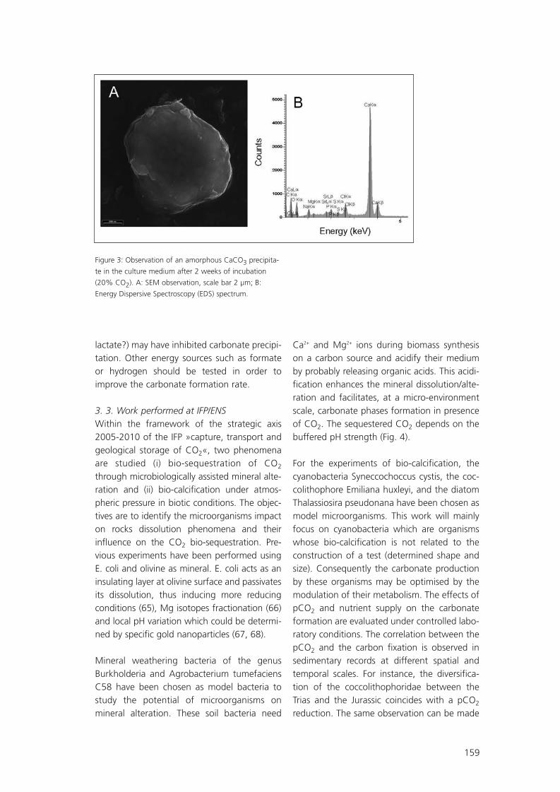
159
lactate?) may have inhibited carbonate precipi-tation. Other energy sources such as formateor hydrogen should be tested in order toimprove the carbonate formation rate.
3. 3. Work performed at IFP/ENSWithin the framework of the strategic axis2005-2010 of the IFP »capture, transport andgeological storage of CO2«, two phenomenaare studied (i) bio-sequestration of CO2
through microbiologically assisted mineral alte-ration and (ii) bio-calcification under atmos-pheric pressure in biotic conditions. The objec-tives are to identify the microorganisms impacton rocks dissolution phenomena and theirinfluence on the CO2 bio-sequestration. Pre-vious experiments have been performed usingE. coli and olivine as mineral. E. coli acts as aninsulating layer at olivine surface and passivatesits dissolution, thus inducing more reducingconditions (65), Mg isotopes fractionation (66)and local pH variation which could be determi-ned by specific gold nanoparticles (67, 68).
Mineral weathering bacteria of the genusBurkholderia and Agrobacterium tumefaciensC58 have been chosen as model bacteria tostudy the potential of microorganisms onmineral alteration. These soil bacteria need
Ca2+ and Mg2+ ions during biomass synthesison a carbon source and acidify their mediumby probably releasing organic acids. This acidi-fication enhances the mineral dissolution/alte-ration and facilitates, at a micro-environmentscale, carbonate phases formation in presenceof CO2. The sequestered CO2 depends on thebuffered pH strength (Fig. 4).
For the experiments of bio-calcification, thecyanobacteria Syneccochoccus cystis, the coc-colithophore Emiliana huxleyi, and the diatomThalassiosira pseudonana have been chosen asmodel microorganisms. This work will mainlyfocus on cyanobacteria which are organismswhose bio-calcification is not related to theconstruction of a test (determined shape andsize). Consequently the carbonate productionby these organisms may be optimised by themodulation of their metabolism. The effects ofpCO2 and nutrient supply on the carbonateformation are evaluated under controlled labo-ratory conditions. The correlation between thepCO2 and the carbon fixation is observed insedimentary records at different spatial andtemporal scales. For instance, the diversifica-tion of the coccolithophoridae between theTrias and the Jurassic coincides with a pCO2
reduction. The same observation can be made
Figure 3: Observation of an amorphous CaCO3 precipita-
te in the culture medium after 2 weeks of incubation
(20% CO2). A: SEM observation, scale bar 2 µm; B:
Energy Dispersive Spectroscopy (EDS) spectrum.
SR09_FGS07.qxd 25.05.2007 14:43 Uhr Seite 159

160
experimentally since a pCO2 enhancement willreduce the carbonate precipitation due to coc-colithophoridae. The opposite correlation isobserved for cyanobacteria since these micro-organisms were more abundant before theMesozoic when the pCO2 was about 100times higher than now. The objective will be tomake mass balances between the carbonates,the CO2 and the organic carbon in order todetermine the possible effect of pCO2 varia-tions on the sedimentation velocities of diffe-rent model organisms. Different pCO2 will betested that represent possible future environ-mental conditions. Other environmental condi-tions that prevailed in the past (correspondingto marked transitions in the carbonate accu-mulation) will be tested as well. This work willalso aim to understand the factors limiting thecapacities of calcifying organisms to fix atmos-pheric CO2 under present natural conditions.
4. ConclusionAs shown in this paper, the current researchactivity in France integrates various aspectsallowing to assess the important role of deepsubsurface microbial organisms in the fate ofthe injected CO2 and the efficiency of itssequestration in a defined reservoir. All thesedevelopments underline the strong need ofexperimental and field investigations in micro-
biology to better understand the influence ofdeep biota on the evolving chemistry andpetrophysic of reservoirs and inversely the injec-tion impact on the microbial ecology of thedeep reservoirs. To predict the consequent envi-ronmental impacts, these have to be integratedin long-term reservoir modelling. This wouldalso allow defining relevant tools to monitorbiogeochemical interactions over the life-timeof the reservoirs. No doubt that the successfulstorage of CO2 in deep reservoirs will requireinterdisciplinary understanding of the criticalcontrolling processes at all time scales.
References1. Amend, J. P. & Teske, A. (2005) Palaeogeogr.,Palaeoclimatol., Palaeoecol. 219, 131-155.
2. Fredrickson, J. K. & Onstott, T. C. (2001) inSubsurface Microbiology and Biogeochemistry,eds. Fredrickson, J. K. & Fletcher, M., NewYork), pp. 3-37.
3. Kieft, T. L. & Phelps, T. J. (1997) in Themicrobiology of the terrestrial subsurface, eds.Amy, P. S. & Haldeman, D. L. (CRC Press, BocaRaton, FL), pp. 137-164.
4. Krumholz, L. (2000) Hydrogeol. J. 8, 4-10.
5. Parkes, R. J. & Wellsbury, P. (2004) in
Figure 4: CO2 quantities produced during mineral altera-
tion and carbon source biodegradation (left); CO2 quanti-
ties sequestered as a function of pH (right)
SR09_FGS07.qxd 25.05.2007 14:43 Uhr Seite 160

161
Microbial diversity and bioprospecting, ed.Bull, A. T. (ASM Press, Washington, D. C.), pp.120-129.
6. Pedersen, K. (2000) FEMS Microbiol. Lett.185, 9-16.
7. Whitman, W. B., Coleman, D. C. & Wiebe,W. J. (1998) Proc. Natl. Acad. Sci. USA 95,6578-6583.
8. Holloway, S. (2001) Annual Review ofEnergy and the Environment 26, 145-166.
9. Aloisi, G., Bouloubassi, I., Heijs, S. K.,Pancost, R. D., Pierre, C., et al. (2002) EarthPlanet. Sc. Lett. 203, 195-203.
10. Basso, O., Lascourreges, J. F., Jarry, M. &Magot, M. (2005) Env. Microbiol. 7, 13-21.
11. McKinley, J. P. & Colwell, F. S. (1996) J.Microbiol. Methods 26, 1-9.
12. D'Hondt, S. L., Jørgensen, B. B., Miller,D. J., Aiello, I. W., Bekins, B., et al. (2003) inProceedings of the Ocean Drilling Vol. 201.
13. Pace, N. R. (1997) Science 276, 734-740.
14. Alazard, D., Dukan, S., Urios, A., Verhé, F.,Bouabida, N., et al. (2003) Int. J. Syst. Evol.Microbiol. 52, 173-178.
15. Audiffrin, C., Cayol, J. L., Joulian, C.,Casalot, L., Garcia, J. L. & Ollivier, B. (2003) Int.J. Syst. Evol. Microbiol. 53, 1585-1590.
16. Magot, M., Basso, O., Tardy-Jacquenod, C.& Caumette, P. (2004) Int. J. Syst. Evol.Microbiol. 54, 1693-1697.
17. Magot, M., Caumette, P., Desperrier, J. M.,Matheron, R., Dauga, C., Grimont, F. & Carreau,L. (1992) Int. J. Syst. Bacteriol. 42, 398-403.
18. Magot, M., Ravot, G., Campaignolle, X.,Ollivier, B., Patel, B. K., et al. (1997) Int. J. Syst.Bacteriol. 47, 818-824.
19. Ollivier, B., Caumette, P., Garcia, J. L. &Mah, R. A. (1994) Microbiol. Rev. 58.
20. Ollivier, B., Cayol, J. L., Patel, B. K. C.,Magot, M., Fardeau, M. L. & Garcia, J. L.(1997) FEMS Microbiol. Lett. 147.
21. Ollivier, B., Fardeau, M. L., Cayol, J. L.,Magot, M., Patel, B. K., Prensier, G. & Garcia,J. L. (1998) Int. J. Syst. Bacteriol. 48, 821-828.
22. Ollivier, B., Hatchikian, C. E., Prensier, G.,Guezenec, J. & Garcia, J. L. (1991) Int. J. Syst.Bacteriol. 41, 74-81.
23. Ollivier, B., Patel, B. K. C. & Garcia, J. L.(2000) in Journey to Diverse Microbial Worlds:Adaptation to Exotic Environments, ed. Seck-bach, J. (Kluwer, the Netherlands, pp. 73-90.
24. Thevenieau, F., Fardeau, M. L., Joulian, C.,Ollivier, B., Zapata, D. & Baena, S. (2006)Extremophiles, in press.
25. Fauque, G. & Ollivier, B. (2003) in MicrobialDiversity and Bioprospecting, ed. Bull, A. T.(ASM Press, Washington D. C.), pp. 169-176.
26. Magot, M. (2005) in Petroleum Micro-biology, eds. Ollivier, B. & Magot, M. (ASMPress, Washington D. C., USA), pp. 21-33.
27. Magot, M., Ollivier, B. & Patel, B. K. C.(2000) Antonie van Leeuwenhoek 77, 103-116.
28.Ollivier, B., Cayol, J. L. & Fauque, G. (2007)in Sulphate-Reducing Bacteria: Environmentaland Engineered Systems, eds. Barton, L. &Hamilton, W. (Cambridge University Press,London), pp. in press.
29.Basso, O., Caumette, P. & Magot, M.(2005) Int. J. Syst. Evol. Microbiol. 55.
30. Nihel, K., Fardeau, M. L., Lascourreges, J. F.,Cayol, J. L., Hacene, H., Thomas, P. & Magot, M.(2007) Int. J. Syst. Evol. Microbiol. (in press).
SR09_FGS07.qxd 25.05.2007 14:43 Uhr Seite 161

162
31. Basso, O. (2005) (Université de Pau et desPays de l'Adour, Vol. Thèse de doctorat.
32. Amann, R., Glöckner, F. O. & Neef, A.(1997) FEMS Microbiol. Rev. 20, 191-200.
33. Lopez-Archilla, A. I., Gérard, E., Moreira, D.& Lopez-Garcia, P. (2004) FEMS Microbiol. Lett.235, 221-228.
34. Gérard, E., Guyot, F., Philippot, P. & Lopez-Garcia, P. (2005) J. Microbiol. Methods 63, 20-28.
35. Ménez, B., Rommevaux-Jestin, C., Salomé,M., Wang, Y., Philippot, P., Bonneville, A. & Gé-rard, E. (2007) Chem. Geol. doi:10.1016/j.chek-geo.2007.02.009.
36. Coleman, M. L., Hedrick, D. F., Lovley, D.R., White, D. C. & Pye, K. (1993) Nature 361,436-438.
37. Haveman, S. A. & Pedersen, K. (2002) J.Cont. Hydrol. 55, 161-174.
38. Mauclaire, L., Mc Kenzie, J. A., Schwyn, B.& Bossart, P. (2007) Phys. Chem. Earth 32.
39. Stroes-Gascoyne, S. & West, J. M. (1997)FEMS Microbiol. Rev. 20, 573-590
40. Stocks-Fischer, S., Galinat, J. K. & Bang, S.S. (1999) Soil Biol. Biochem. 31, 1563-1571.
41. Van der Lee, J. (1998) Technical ReportLHM/RD/98/39, CIG, Ecole des Mines de Paris,Fontainebleau, France.
42. Steefel, C. I. (2001) User’s Guide, UCRL-MA-143182, Livermore, California.
43. Ehrlich, H. L. (2002) in Geomicrobiology,4th edition (Marcel Dekker, New York).
44. Haszeldine, R. S., Quinn, O., England, G.,Wilkinson, M., Shipton, Z. K., et al. (2005) OilGas Sc. Tech. 60, 33-49.
45. Rauzi, S. L. (1999) Arizona Geological Sur-vey Open file report 99-2.
46. Aloisi, G., Gloter, A., Krüger, M., Wall-mann, K., Guyot, F. & Zuddas, P. (2006) Geo-logy 34, 1017-1020.
47. Fujita, Y., Ferris, F. G., Lawson, R. D.,Colwell, F. S. & Smith, R. W. (2000) Geo-microbiol. J. 17, 305-318.
48. Gouze, P., Noiriel, C., Bruderer, C., Loggia, D.& R., L. (2003) Geophys. Res. Lett. 30, 195-243.
49. Noiriel, C., Gouze, P. & Bernard, D. (2004)Geophys. Res. Lett. 31, L24603, doi:10.1029/2004GL021572.
50. Templeton, A. S., Trainor, T. P., Traina, S. J.,Spormann, A. M. & Brown, J., G. E. (2001)Proc. Natl. Acad. Sci. USA 98, 11897-11902.
51. Azaroual, M., Fouillac, C. & Matray, J. M.(1997) Chem. Geol. 140, 167-179.
52. Dupraz, S., Ménez, B. & Guyot, F. (2007)Geophys. Res. Abstr. 9, 03967.
53. Dupraz, S., Ménez, B., Parmentier, M. &Guyot, F. Geochim. Cosmochim. Acta, to besubmitted.
54. Eichler, B. & Schink, B. (1984) Arch. Micro-biol. 140, 147-152.
55. Benzerara, K., Barakat, M., Menguy, N.,Guyot, F., De Luca, G., Audrain, C. & Heulin, T.(2004) Geomicrobiol. J. 21, 341-349.
56. Benzerara, K., Menguy, N., Guyot, F.,Skouri, F., de Luca, G., Barakat, M. & Heulin, T.(2004) Earth Planet. Sc. Lett. 228, 439-449.
57. Benzerara, K., Menguy, N., Guyot, F., Van-ni, C. & Gillet, P. (2005) Geochim. Cosmochim.Acta 69, 1413-1422.
SR09_FGS07.qxd 25.05.2007 14:43 Uhr Seite 162

163
58. Benzerara, K., Menguy, N., Lopez-Garcia,P., Yoon, T.-H., Kazmierczak, J., et al. (2006)Proc. Natl. Acad. Sci. USA 103, 9440-9445.
59. Benzerara, K., Yoon, T. H., Menguy, N.,Tyliszczak, T. & Brown, J., G. E. (2005) Proc.Natl. Acad. Sci. USA 102, 979-982.
60. Benzerara, K., Yoon, T. H., Tyliszczak, T.,Constantz, B., Spormann, A. M. & Brown, J.,G. E. (2005) Geobiol. 2, 249-259.
61. Van Lith, Y., Warthmann, R., Vasconcelos,C. & Mc Kenzie, J. (2003) Geobiol. 1, 71-79.
62. Warthmann, R., Van Lith, Y., Vasconcelos,C., Mc Kenzie, J. & Karpoff, A. M. (2000)Geology 12.
63. Fardeau, M. L., Goulhen, F., Bruschi, M.,Khelifi, N., Cayol, J. L., et al. (2007) FEMSMicrobiology Ecology, submitted.
64. Ignatiadis, I., Amalhay, M., Abou Akar, A.& Cotiche, C. (1998) in Biodétérioration desmatériaux, eds. Lemaître, C., Pébère, N. &Festy, D. (EDP Sciences, Les Ulis, France).
65. Garcia, B., Lemelle, L. & Gillet, P. Chem.Geol., to be submitted.
66. Garcia, B., Lemelle, L., Rose-Koga, E. F.,Telouk, P., Gillet, P. & Albarède, F. Chem. Geol.,to be submitted.
67. Garcia, B., Salomé, M., Lemelle, L., Bridot,J. L., Gillet, P., et al. (2005) Chem. Commun.,369-371.
68. Roux, S., Garcia, B., Bridot, J. L., Salomé,M., Marquette, C., et al. (2005) Langmuir 21,2526-2536.
SR09_FGS07.qxd 25.05.2007 14:43 Uhr Seite 163

164
Research and Developments needs and sche-dule For an industrial deployment of carbonsequestration in 2020 Point of view of anindustry actor in Underground Gas Storage
Géostock is bringing its experience comingfrom day-to-day operations and design ofunderground gas storage facilities to variousR&D projects in France. The technology deri-ved from underground gas storage (from cha-racterisation of sites down to post-injectionmonitoring and follow-up), which has beendeveloping for more than 80 years, gives a safeand solid ground for future projects aimed atgeological storage of carbon dioxide. Issuesrelated to specific geochemistry, induced geo-mechanics and hydro-dynamism of carbon dio-xide injection are today largely dealt withthrough numerous R&D projects around theworld, some of then being financed by the
French National Research Agency. Keeping inmind year 2020 as the ultimate horizon forindustrial deployment of CCS, in order to copewith internationally accepted goals for reduc-tion of greenhouse gases, the laboratory expe-riments and digital simulations are starting tomake benefit of a feed-back coming from pilotprojects. This »return from experience« shouldbe accelerated in the coming years with asmany as possible pilot projects launched inEurope, in order for regulatory frameworksand sites qualification criteria to be adapted.
Munier G.
Géostock
SR09_FGS07.qxd 25.05.2007 14:43 Uhr Seite 164

165
Fiber optic evanescent-field-sensor for the CO2 – monitoring
For the online und insitu monitoring of CO2
during the sequestration process methods areneeded which require no sample taking. Oneof those is the evanescent-field-laserspectro-scopy in the near infrared spectral region thatuses optical fibers or multireflection elementsas sensing elements.
A single-mode distributed feedback (DFB) laserdiode with an emission wavelength around1.57 µm is used as a light source. A fused silicamultimode optical fiber with a core diameter of200 µm coiled on a teflon holder, is used as sen-sor element. The jacket and the cladding of thefiber are removed in the sensing region, so thatinteraction between the fiber and the surroun-ding medium can take place. The length of theactive sensing part is about 4m. The laser light iscoupled into the fiber and the transmittedintensity is measured with an infrared photodio-de. The experimental setup is shown in fig.1.
The operation principle of such sensors isbased on the total reflection at the interfacebetween two media with different index ofrefraction. When the totally internally reflectedray penetrates into the thin medium, an eva-nescent wave is built parallel to the interfaceand its amplitude decreases exponentially. Thisfield is called the evanescent field.
If the thin medium is non-absorbing, no changesin the intensity occur. If the thin medium is anabsorbing one, the intensity of the evanescentwave in this medium is attenuated and the trans-mitted power is reduced. These losses are usedas criterion for the detection of absorbing mate-rials. The major advantage of this technique isthat the sensing region can be inserted into flu-ids, so that the real-time determination of theCO2-content in water is possible. Measurements in the gas and fluid phase are done at this time in laboratory and will be presented.
Orghici R. , Willer U., Schade W.
Institut für Physik und Physikalische Technologien, Technische Universität Clausthal, Leibnizstrasse 4,
38678 Clausthal Zellerfeld, Germany
Figure 1: Schematic diagram of the setup.
SR09_FGS07.qxd 25.05.2007 14:43 Uhr Seite 165

166
Are »caprocks« safe seals for CO2?
IntroductionThe constant increase of carbon dioxide in theatmosphere is regarded as being the principalcause of the current global warming (Fluteau,2003). Geological sequestration seems to beone of the key solutions to reduce the increa-se of greenhouse gases (of which CO2 is one)in the atmosphere (Jean-Baptiste and Ducroux,2003; Little et al., 2004). A potential CO2 reser-voir must fulfil several conditions: the storagecapacities must be sufficiently high, the reser-voir must keep its integrity for several hund-reds or thousands of years, the reservoir musthave a low environmental impact and alsoneeds to be economically viable and conformto contemporary laws and regulations (Bachu,2002; IEA, 2001). Two main options have beenproposed to store CO2 in deep geological for-mations: i) saline aquifers, which represent thegreatest storage capacity in the long-term,demonstrated at Sleipner (IEA, 2001; Kongs-jorden et al., 1997; Torp and Gale, 2004), ii)depleted hydrocarbon reservoirs, where CO2
injection can be associated with enhancedoil/gas recovery, as in the Weyburn site(Canada) (Emberley et al., 2004).
CO2 can be trapped in three different forms(Hitchon, 1996): (1) as a supercritical phase(hydrodynamic trapping); (2) dissolved in porewater (trapping by solubility); (3) by carbonateprecipitation (mineralogical trapping) (Xu et al.,2000; Emberley et al., 2004, IPCC, 2005; Gale,2004). CO2 storage is generally expected to
take place at depths below 800m, where theambient pressures and temperatures will usu-ally result in CO2 being in a liquid or supercriti-cal state. Under these conditions, the densityof CO2 will range from 50 to 80% of the den-sity of water and the injected CO2 will risebuoyantly to the top of the reservoir structureand accumulate beneath the caprock, a low-permeable and porous material saturated withbrine. Vertical movement of CO2 may result indriving forces, including diffusion, buoyancyand regional hydraulic gradient. Storage safetyis thus limited by the caprock’s ability to retainthe trapped CO2 over very long periods oftime. CO2 leakage processes through thecaprock must be evaluated prior to any CO2
storage project.
Several origins for caprock failure in presenceof CO2 can be listed:- CO2 diffusion through the caprock formation,- Capillary breakthrough via a permeable
path (pore network or pre-existing or crea-ted microcracks) through the caprock,
- Leakage of CO2 through cracks created byhydraulic fracturing during the injection,
- Creation of new flow paths by dilatancy ofthe cap rock induced by overpressure,
- Chemical alteration of the mineralogicalassemblage of the caprock formation,
- Migration of CO2 through pre-existing frac-tures re-opened by chemical alteration ofthe mineral filling.
Pironon J. (1), Hubert G (1), Delay J. (2), Vinsot A. (2), Bildstein O. (3), Jullien M. (3), Chiquet P. (4,5),
Broseta D. (5), Lagneau V. (6)
(1) INPL (Images), Nancy Université, CNRS, BP 239, 54506 Vandoeuvre-lès-Nancy, France
(2) ANDRA, Laboratoire de recherche souterrain de Meuse/Haute-Marne, 55290 Bure, France
(3) CEA-Cadarache, 13108 St Paul-lez-Durance, France
(4) TOTAL, CSTJF, Avenue Larribau, 64018 Pau, France
(5) LFC, Université de Pau et des Pays de l’Adour, BP 1155, 64013 Pau, France
(6) Centre de Géosciences, École des Mines de Paris, 77305 Fontainebleau Cedex, France
SR09_FGS07.qxd 25.05.2007 14:43 Uhr Seite 166

167
In addition to these »natural« pathways,»anthropogenic« pathways such as existingboreholes must be considered. Carey et al.(2005) described alteration at the seal-wellbo-re interface after samples of cement and sha-les were recovered from a well used in a long-term CO2 enhanced oil recovery operationduring 30 years (SACROC unit, Permian Basin,Texas). There was evidence for CO2 migrationalong the casing-cement and cement-shaleinterfaces, marked by precipitation of poly-morphs of calcium carbonate (calcite, aragoni-te and vaterite). Since transport of CO2
through »anthropogenic« pathways may be ofthe order of tens to hundreds of years, naturalpathways can lead to very slow transport ontimescales of tens of thousands of years (Celiaand Bachu, 2002, Savage et al., 2003). Forexample, Lindeberg and Bergmo (2003) simula-ted the behaviour of CO2 injected into anunderground aquifer. They concluded i) thatthe long-term fate of CO2 in a reservoir willdepend on the topography of the cap rock, ii)most of the CO2 should dissolve in the brinebetween 5 000 and 50 000 years, iii) and CO2
should reach the surface after molecular diffu-sion through a capillary seal of 700 m in depthafter more than 500 000 years. The time forCO2 dissolution into the brine of the reservoirshould be shorter, on the order of hundreds ofyears taking into account convective mixingrather than pure diffusion (Ennis-King andPatterson, 2005). Diffusion will not have realclimatic impact at a time-scale shorter than thelong ice-age cycle (100 000 years). The futuresites of CO2 storage must be monitored, inparticular via seismic 3D, which is an essentialtool to understand the evolution of the CO2
plume in the reservoir (Arts et al., 2004). A leakof a CO2-rich fluid towards the outside of thereservoir can have dramatic consequences onthe environment and human beings (Wangand Jaffe, 2004).
The study of integrity of caprocks is the objec-tive of the Geocarbone-Intégrité programmesupported by the French National ResearchAgency (ANR-05-CO2-006), which bringstogether eleven partners from academia and
industry. All are involved in the different topicslisted above. Only capillary breakthrough, che-mical alteration and migration through fractu-res will be discussed in this paper.
Characterisation of the caprockEfficient caprocks overlying reservoirs are usu-ally composed of salt or clay formations. Clayformation is the target of the Geocarbone-Intégrité programme considering a possibleCO2 storage site in the Dogger limestones ofthe central Paris basin at Saint-Martin deBossenay. The limestones are locally oil reser-voirs or aquifers.
Such low permeability rocks are well known inFrance, because they are considered to begood candidates for nuclear waste storage.Because of the small size of their pores, theirraised tortuosity, their important specific surfa-ce and their high polarity, the clay materialsexhibit very good containment properties(Jullien et al., 2005). Of course, CO2 cannot becompared to nuclear wastes, but a good scien-tific approach to the integrity of seals musttake into account the experience acquired overmore than 20 years on clay formations by thecommunity involved in nuclear waste storage.Since 1999, the French National RadioactiveWaste Management Agency (Agence nationa-le pour la gestion des déchets radioactifs –Andra) has been constructing an undergroundtest facility to study the feasibility of a radioac-tive waste disposal in the Jurassic-age Callovo-Oxfordian argillites. The geological formationunder consideration is a 130-m-thick layer ofargillaceous rocks that lies between about 420and 550 m below the surface and is probablythe best caprock-equivalent based on itshomogeneity and lateral extension throughthe Paris basin.
The main objective of the research is to cha-racterize the confining properties of the argil-laceous rock through in situ water and gashydrogeological tests, chemical measurementsand diffusion experiments. In order to achievethis goal, a fundamental understanding of thegeoscientific properties and processes that
SR09_FGS07.qxd 25.05.2007 14:43 Uhr Seite 167

168
govern geological isolation in clay-rich rockshas been acquired. This understanding inclu-des both the host rocks at the laboratory siteand the regional geological context. From 1994 to 2003, the mapping survey andborehole drilling work performed in a sectorcovering several hundreds of square kilometersmade it possible to identify the properties ofsedimentary formations over a thickness ofapproximately 700 m including the Callovo-Oxfordian formation (Delay et al, 2007a). Thesurveying process was very significantly refinedon-site (Meuse/Haute-Marne undergroundresearch laboratory construction site) througha series of directional boreholes whose purpo-se was to identify the petrophysical and hydro-geological properties and variability of theCallovo-Oxfordian formation.
In 2004, Andra started a new phase of itsexperimental programme in the drifts of theUnderground Research Laboratory (URL) (Delayet al, 2007b). The Laboratory consists of twoshafts, an experimental drift at 445 m depthand a set of technical and experimental driftsat the main level at 490 m depth (Figure 1).
Containment capability comes from the speci-fic physical characteristics of the rock and thephysico-chemical characteristics of the intersti-tial fluids and their interaction with the rock.The fundamental physical characteristic is per-meability. The results obtained from measure-ments carried out on samples, as well asthrough a series of tests carried out in deep
boreholes from the surface and short boreho-les from the experimentation drift at 445-mdepth, are coherent, although the methodsand investigation scales are different. At thescale of the laboratory site, permeability isbelow 10-12 ms-1 over the entire thickness of theargillaceous formation, with a minimum valueestimated at 10-14 ms-1 (Delay et al., 2006). Thechemical characteristics of the interstitial fluidscondition the mobility of the various radionu-clides likely to be found in the natural environ-ment. The studies focus on knowledge of thegeochemistry of the interstitial fluids in equili-brium with the minerals in the rock and on thediffusion and retention capabilities of theradionuclides.
During the seven years of construction workand scientific experiments, more than 180boreholes have been drilled. They are almostall equipped with various types of completions.Currently more than 1800 transducers andscientific probes are continuously monitoredon-line. Some geochemical equipment isremotely operated through the internal net.
The mineralogy of the argillites has been deter-mined using FTIR, X-ray diffraction (XRD), DTA,gas adsorption, Scanning electron microscopy(SEM) coupled to an energy-dispersion spec-trometer (EDS) and TEM. The mineralogicalcomparison between one sample originatingfrom the RIO carbonate rich level of theCallovo-Oxfordian argillites of Bure and threesamples of the same geological formation at
Figure 1: Left: location of Saint-Martin de Bossenay area and the Underground Research Laboratory of Meuse/Haute-
Marne at Bure. Right: general layout drawing of the Meuse/Haute-Marne URL drifts.
SR09_FGS07.qxd 25.05.2007 14:43 Uhr Seite 168

169
Saint-Martin de Bossenay shows good agree-ment in terms of mineral content and relativeproportion (Figure 2). A detailed description ofmineralogical data of the Callovo-Oxfordianformation around Bure based on numeroussample analyses can be found in Andra (2005).This geological layer shows a remarkablehomogeneity over long distances in terms ofmineral composition: carbonates (calcite), clays(interstratified illite/smectite and illite), andquartz. The experience of the URL can be easi-ly transferred to the study of the caprock atSaint-Martin de Bossenay.
Geochemical and geomechanical reactivityThe experimental studies aim at gaining know-ledge of the processes that govern geologicalisolation and determining the controlling para-meters of these processes in order to assess thelong-term sequestration of CO2. The experi-ments mainly focus on the confinement proper-ties of the caprock argillites described aboveand on the mechanisms by which CO2 mightleak and escape from the depleted oil reservoiror the saline aquifer. To investigate the geoche-mical reactivity two main types of experimentswere designed to explore the two key scenariosof the performance and safety assessment:batch systems to look at the geochemical reac-tivity of CO2 (in dissolved and in supercriticalform) with the mineral assemblage of the cap-rock, and percolation systems to look at reacti-ve flow of supercritical CO2 (CO2-SC) throughchemically or mechanically activated fractures.
The operating mode for the batch experimentsis to start reactivity experiments with an initialwater composition as close as possible to theformation brine or a composition at equili-brium with the mineral assemblage. This watercomposition is then modified to match theexpected conditions after CO2 injection: equili-bration with CO2 gas or CO2-SC. For the batchexperiments performed at the CEA inCadarache with the SMB samples, the rocksamples are crushed and reduced to powder (< 500 µm), to maximize the reactive specificsurface, and then placed into a titanium auto-clave where fluids are maintained at constanttemperature and pressure. The initial waterwas synthesised from the composition given byAzaroual et al. (1997). Four sets of experimentswere systematically carried out: SMB withbrine, SMB with brine acidified with CO2(g),SMB with dry CO2-SC, and SMB with brine andCO2-SC. The pressure was maintained at 150bars during 30/90 days and two temperatureswere chosen for the experiments: 80°C whichis the temperature at the depth of the caprockat SMB, and 150°C which allows for an activa-tion of slow reactions in order to extrapolateresults for the long term assessment of thecaprock reactivity. For each of the tests, threereplicates of brine were analysed before andafter reaction by inducted coupled Plasma –Atomic Emission Spectrometer (ICP-AES).Preliminary results show that the reactivity ofminerals with dry CO2-SC is not significant (thisresult has to be confirmed, see Regnault et al.,2005). In contrast, significant changes were
Figure 2: Mineralogical comparison between Callovo-Oxfordian argillites from Saint-Martin de Bossenay (SMB) and one
sample of the RIO carbonate rich level from the Underground Research Laboratory of Bure.
SR09_FGS07.qxd 25.05.2007 14:43 Uhr Seite 169

170
found when brine was present, resulting in adestabilisation of clay minerals and precipita-tion of calcium sulfates and carbonates.
The same kind of experiments were carried outwith pure homoionic Ca-Montmorillonite andwith Bure claystone at INPL-Nancy. In this case,the crushed samples were placed into smallgold capsule cells together with the brine anddry CO2 ice. The conditions of the experimentwere similar to those described above.Different solutions were used: brine which waspreviously equilibrated during one week withthe powder, the same brine acidified withCO2(g), with CO2-SC. A series of experiments areperformed at a pressure of 150 bars and atemperature of 80°C and 150°C during twoand six months. First results on the aging ofCa-Montmorillonite at 150°C in the presenceof aqueous brine show dissolution and recry-stallization of Ca-Na-Montmorillonite with adecrease of the interlayer charge and an incre-ase of the Al content in the octahedral layerassociated with iron oxide and silica precipita-tion.For the second type of experiments originaldevices were designed at the CEA inCadarache (Figure 3) and at INPL in Nancy toinvestigate the percolation of CO2-SC throughfractured or non-fractured samples respective-ly. The device developed at the CEA is compo-sed of a triaxial confinement cell with a seriesof injection pumps for CO2. The mechanicalintegrity of the fractured sample is assured by
the counter-pressure exerted by a confiningfluid on the protective tube containing thesample. At the moment, the devices are in atesting phase. In parallel, geomechanical cha-racterisations are also performed to determinethe deformation properties of the caprock(elastic properties, fracturing strength, …). Inorder to evaluate the damage caused by geo-chemical alteration this type of characteriza-tion is also planned for pristine caprock plugsand for plugs that underwent degradation dueto interaction with CO2-SC and brine.
Geochemical simulationsGeochemical models were developed to simu-late the batch experiments. These models havebeen subsequently extrapolated in time andspace to simulate the long term behaviour ofthe caprock in contact with large quantities ofCO2. The simulations presented here havebeen carried out using the geochemical speci-ation code CHESS, and its companion coupledhydrodynamics and reactions code HYTEC,both developed at the Ecole des Mines de Paris(van der Lee et al, 2002, 2003, see Le Gallo etal., this issue).
Simulation of Batch Experiments A model SMB rock sample was prepared basedon mineralogical observations (Table 1). Calciteand anhydrite are considered at equilibrium, butall other mineral reactions are kinetically control-led. This paper focuses on reactions with thereservoir-like water equilibrated with supercritical
Figure 3: Triaxial percolation cell for reactive CO2 –SC flow-through experiments at the CEA Cadarache.
The oven (left picture) containing the experimental cell (in the middle) allows for complete temperature control.
CO2 gas is injected with a series of pumps (at the left and right of the oven), which maintain the pressure inside the
cell. CO2 becomes supercritical due to temperature increase in the heating coil (hc). It then reacts with the fractured
sample inside the cell (right picture).
SR09_FGS07.qxd 25.05.2007 14:43 Uhr Seite 170

171
CO2 at 80°C-160 bar ([CO2(aq)]=0.997 molal,see fluid composition Table 2): a three-monthlong simulation has been carried out, with1.25 g of rock in contact with 50 ml of solutionin open system (an excess supercritical CO2
maintaining the aqueous CO2 concentration).
The low initial pH induces complete dissolutionof the calcite and prevents the precipitation ofdolomite. The silicate system, with slower kine-tic rates, starts reacting but remains far fromequilibrium. The reactions are characterised bydissolution of illite and Ca-montmorilloniteand precipitation of kaolinite and quartz (ofthe order of -0.2% for Ca-montmorillonite and+1.1% for kaolinite). The excess dissolved cal-cium and magnesium stays in solution, as thecarbonates are still under-saturated.
More long-term batch reactions have beensimulated. On longer time scales, the silicatesystem continues its evolution, with a succes-sion of reaction paths (Figure 4A). The reactionpath starts with the dissolution of illite and Ca-montmorillonite associated with the precipita-tion of kaolinite and a slow precipitation ofquartz (t=0 to 16 y). The very slow precipita-tion of quartz cannot control all the dissolvedsilica produced by the dissolution of illite.
When the build-up in silica is sufficient, thereaction path changes into illite dissolutionwith associated precipitation of Ca-montmoril-lonite, kaolinite and quartz (t=16 to 300 y). At t=300 y, the illite is nearly completely dis-solved, its reactive surface and reaction ratedrops, and it ceases to control the dissolvedaluminium. A third reaction path starts, withthe dissolution of Ca-montmorillonite and pre-cipitation of kaolinite and quartz, until theexhaustion of the Ca-montmorillonite (t=300 yto 32 ky). At 14 ky, the build-up in calcium andmagnesium is enough to allow the precipita-tion of dolomite.
Coupled reactions and transportTaking the batch simulations further, the che-mical problem has been transposed into areactive transport setting: contact between aCO2-rich reservoir and a cap-rock. The chemi-stry of the cap-rock is identical to the batchsamples, with an initially equilibrated interstiti-al fluid. Several configurations have beentested: 1D diffusive transport at the interface,weak upward advective transport to simulate apressure gradient due to the buoyancy of CO2,and 2D heterogeneous geometry with explicitfracturing. Note that the system was conside-red single (water and dissolved CO2) phase.
Table 1: mineralogy of the model SMB rock sample (in g).
Table 2: sample properties of the reacting fluids(concentrations are total dissolved species in mmolal,
temperature = 80°C). Other components (Mg, Ca, Fe, Al, …) are not reported here.
SR09_FGS07.qxd 25.05.2007 14:43 Uhr Seite 171

172
Results from the 1D diffusive (and slow advec-tion) simulations show a very slow progressionof a reacting front on a 1000 y timescale(Figure 4B). The reaction fronts for calcite anddolomite are very slow, and are not expectedto markedly modify the caprock properties.Due to the slow kinetics, the silicates do notdisplay reaction fronts: the reactions occurslowly, on a longer range, with an even lowerimpact on porosity.
However, heterogeneities can strongly enhan-ce the impact on the caprock, by concentra-ting the reactions on smaller spatial ranges.The presence of fractures has thus been tested,
both by explicit vertical fractures in 2D simula-tions and by using 1D double porosity models.Fractures are initially filled with calcite, withpermeabilities initially three orders of magnitu-de larger than in the caprock. In both cases,the simulation results display a faster velocityinside the fracture (succession of calcite-dolo-mite fronts). Moreover, the rapid advancementof aggressive water inside the fracture has animpact on the caprock in the vicinity of thefracture (Figure 5), with enhanced reactions asfar as the reaction front inside the fracture; onthe other hand, the reacting fronts far fromthe fracture are very slow (similar to 1D advec-tive simulation).
Figure 4:
A: Calculated mineral evolution in the extended supercritical CO2 batch experiment: illite dissolves throughout the evo-
lution, with precipitation of kaolinite, dolomite appears after 10 ky.
B: Calculated profiles at time 1000 y of degradation of the caprock due to CO2-rich fluid progression, diffusive and
slightly advective cases. The velocity of the reacting front displacement is very slow and no real degradation of the
caprock properties is expected.
Figure 5: Effect of a discrete hetero-
geneity on the simulation. left: calcite
fronts inside and in the vicinity of a
fracture (first column of cells on the
left). right: porosity increase (%) in
the vicinity of the fracture. Note: the
x-scale is enlarged for better reading.
SR09_FGS07.qxd 25.05.2007 14:43 Uhr Seite 172

173
The presence of a fracture thus canalizes thereactions along the fracture (calcite, dolomite),with an effect on the close vicinity of the frac-ture for all the mineralogy. The impact in termsof caprock integrity is predictable, with the dis-solution of all the minerals inside the fracture,and an increase of 25% of the porosity in thevicinity of the fracture. However, the transfor-mation of an observed mean mineralogical(and porosity) variation into permeability chan-ges is not simple: these relations will have tobe designed carefully, according to the localpore structure and its evolution.
Finally, it is essential to bear in mind that theimportant point is not the impact of the reac-tions on the mineralogy in itself, but the evo-lution of the CO2 migration rate according tothe scenarios and the degradation of thecaprock. Simulations are being carried out toquantify the fluxes of CO2 on a medium scale(~10 m) according to several scenarios.
Capillary breakthroughIf CO2 leakage can occur subsequent to thepressure build up and temperature decreaseresulting from the CO2 injection, via pre-exi-sting or hydraulic or thermal newly formedfractures of the caprock, it may also occur bycapillary breakthrough of the CO2 phase.In aquifers, there is no proven capillary barrierof the caprock with respect to CO2, while in
hydrocarbon reservoirs the initial capillary bar-rier is indeed proven, but with respect tohydrocarbons. As illustrated in the followingimage, this capillary barrier is an interfacialeffect. In fact, caprocks are fine (usually clayey,but sometimes evaporitic) porous media imbi-bed with water (brine), most often at hydro-static pressure. Breakthrough of CO2 occurs,i.e., water is displaced by CO2, when the radiusof curvature of the water-CO2 menisci (seeFigure 6) reaches a characteristic pore radius Rcharacteristic of the caprock structure. Thiscorresponds to an excess pressure in the CO2
phase (as compared to the water or hydrosta-tic pressure Pw) given by the Laplace law:
(1)
where γw,CO2 is the interfacial tension betweenthe water and CO2 phases, and θ the contactangle (in water) of the rock substrate/water/CO2
system. The caprock's capillary-sealing efficiencywith respect to CO2 is quantified by this excesspressure, which is nothing more than the capil-lary entry pressure Pce of CO2 into the water-fil-led caprock; this pressure can itself be easilyconverted into a maximum height of storedCO2, i.e., into a storage capacity.
From Equation (1) it is clearly apparent that agood capillary barrier is provided by a largeenough water-CO2 interfacial tension and a
Figure 6: Schematic representation of the interfacial phenomena involved in capillary retention of CO2 (stored in the
reservoir-rock) by the water-imbibed caprock.
SR09_FGS07.qxd 25.05.2007 14:43 Uhr Seite 173

174
good water-wettability (i.e., a small enoughcontact angle ı) of the caprock substrate.Those two properties have been examinedunder the conditions of CO2 geological stora-ge, i.e., at high pressures and temperatures.
Water-CO2 interfacial tensions (IFTs) have beenmeasured by the pendent drop technique in atemperature and pressure interval of 35-110°Cand 50-450 bar. Perhaps the most interestingresult from the point of view of CO2 geologicalstorage is that water-CO2 IFT values are signifi-cant – above 20 mN/m – at high pressures andtemperatures (Chiquet et al., 2007a,b).
On the other hand, contact angle measure-ments with planar substrates representative ofcaprock minerals, such as mica (representativeof illite) and quartz, demonstrate that denseCO2 has a detrimental effect on water-wetta-bility. These measurements have been carriedout at 35°C and in a pressure range of 10-110bar using an optomechanical setup that allowsthe measurement of both the advancing andreceding angles (in water) – only the latter isrelevant here. The results, depicted in the fol-lowing figure 7, indicate that CO2 alters thewater-wettability of mineral substrates: thealteration is more pronounced in the case ofmica than in the case of quartz. One importantcause of such wetability alteration is the decre-ase of brine pH that follows CO2 dissolution.
The pH decreases to values in the range of 3 athigh pressure (> 80 bar) strongly reducing thesurface negative charges carried by the mine-ral/brine interfaces, thus depressing the elec-trostatic interfacial repulsion between mine-ral/brine and brine/CO2 interfaces.
The low (but finite) values of water/CO2 IFTand the alteration of water-wettability ofcaprock minerals by dense CO2 are detrimentalto CO2 geological storage because they inducelower CO2 breakthrough pressures across thecaprock. A careful analysis of recent capillarybreakthrough experiments in both shaly(Hildenbrand et al., 2004) and evaporitic (Li etal., 2005) caprocks confirms this expectation:the apparent contact angles inferred from thebreakthrough pressures are significantly above0°, which is in line with the above observationsof contact angles on model (planar) substratesunder similar pressure conditions.
These results have an impact, not only for thesafety of geological storage, but also for stora-ge capacity: because of the differences in con-tact angles and interfacial tensions with water,CO2 leaks more easily (i.e., at lower pressures)than hydrocarbon (e.g., CH4) through a givencaprock. This has to be taken into account whenestimating the maximum CO2 storage pressureand CO2 storage capacity in depleted hydrocar-bon reservoirs and deep saline aquifers.
Figure 7: Contact angles corresponding to the drainage of the water phase by CO2 at 35°C as a function of pressure
for mica (left) and quartz (right).
SR09_FGS07.qxd 25.05.2007 14:43 Uhr Seite 174
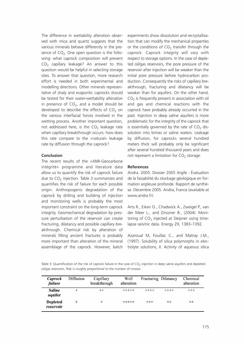
175
The difference in wettability alteration obser-ved with mica and quartz suggests that thevarious minerals behave differently in the pre-sence of CO2. One open question is the follo-wing: what caprock composition will preventCO2 capillary leakage? An answer to thisquestion would be helpful in selecting storagesites. To answer that question, more researcheffort is needed in both experimental andmodelling directions. Other minerals represen-tative of shaly and evaporitic caprocks shouldbe tested for their water-wettability alterationin presence of CO2, and a model should bedeveloped to describe the effects of CO2 onthe various interfacial forces involved in thewetting process. Another important question,not addressed here, is the CO2 leakage ratewhen capillary breakthrough occurs: how doesthis rate compare to the »natural« leakagerate by diffusion through the caprock?
ConclusionThe recent results of the »ANR-Géocarboneintégrité« programme and literature dataallow us to quantify the risk of caprock failuredue to CO2 injection. Table 3 summarizes andquantifies the risk of failure for each possibleorigin. Anthropogenic degradation of thecaprock by drilling and building of injectionand monitoring wells is probably the mostimportant constraint on the long-term caprockintegrity. Geomechanical degradation by pres-sure perturbation of the reservoir can createfracturing, dilatancy and possible capillary bre-akthrough. Chemical risk by alteration ofminerals filling ancient fractures is probablymore important than alteration of the mineralassemblage of the caprock. However, batch
experiments show dissolution and recrystallisa-tion that can modify the mechanical propertiesor the conditions of CO2 transfer through thecaprock. Caprock integrity will vary withrespect to storage options. In the case of deple-ted oil/gas reservoirs, the pore pressure of thereservoir after injection will be weaker than theinitial pore pressure before hydrocarbon pro-duction. Consequently the risks of capillary bre-akthrough, fracturing and dilatancy will beweaker than for aquifers. On the other hand,CO2 is frequently present in association with oiland gas and chemical reactions with thecaprock have probably already occurred in thepast. Injection in deep saline aquifers is moreproblematic for the integrity of the caprock thatis essentially governed by the rate of CO2 dis-solution into brines or saline waters. Leakageby diffusion, for caprocks several hundredmeters thick will probably only be significantafter several hundred thousand years and doesnot represent a limitation for CO2 storage.
ReferencesAndra. 2005. Dossier 2005 Argile : Évaluationde la faisabilité du stockage géologique en for-mation argileuse profonde. Rapport de synthè-se. Décembre 2005. Andra, France (available atwww.andra.fr).
Arts R., Eiken O., Chadwick A., Zweigel P., vander Meer L., and Zinszner B., (2004). Moni-toring of CO2 injected at Sleipner using time-lapse seismic data. Energy 29, 1383–1392.
Azaroual M, Fouillac C., and Matray J.M.,(1997). Solubility of silica polymorphs in elec-trolyte solutions, II. Activity of aqueous silica
Table 3: Quantification of the risk of caprock failure in the case of CO2 injection in deep saline aquifers and depleted
oil/gas reservoirs. Risk is roughly proportional to the number of crosses.
SR09_FGS07.qxd 25.05.2007 14:43 Uhr Seite 175

176
and solid silica polymorphs in deep solutionsfrom the sedimentary Paris Basin, ChemicalGeology, 140, 3-4, pp. 67-179.
Bachu S., 2002. Sequestration of CO2 in geo-logical media in response to climate change :road map for site selection using the transformof the geological space into the CO2 phasespace. Energy Conversion and Management43, 87-102.
Carey J.W., Wigand M., Chipera S.,Woldegabriel G., Pawar R., Lichtner P.C.,Wehner S., Raines M., and Guthrie G.D. (2005)Analysis of the wellbore seal at well 49-6 in theSACROC CO2 Enhanced Oil Recovery Field,West Texas. American Geophysical Union, FallMeeting, abstract #GC13A-1222.
Chiquet P., Broseta D., and Thibeau S. (2007a)Wettability alteration of caprock minerals bycarbon dioxide. Geofluids 7, 112-122.
Chiquet P., Daridon JL, Broseta D., andThibeau. S. (2007b) CO2/water interfacial ten-sions under the pressure and temperature con-ditions of geological storage. Energy Conver-sion and Management 48, 736-744
Delay, J. Trouiller, A. and Lavanchy, J.M. (2006).Propriétés hydrodynamiques du Callovo-Oxfordien dans l’Est du bassin de Paris : comparaison des résultats obtenus selon diffé-rentes approches, C. R. Geosciences, 338(12-13) : 892-907.
Delay, J. Rebours, H. Vinsot, A. and Robin, P.(2007a). Scientific Investigation in deep wellsat the Meuse/Haute-Marne underground rese-arch laboratory, northeastern France. Physicsand Chemistry of the Earth, 32 (1-7), 42-57.
Delay, J. Vinsot, A. Krieguer, J.M., Rebours, H.and Armand, G. (2007b). Making of the un-derground scientific experimental programmeat the Meuse/Haute-Marne underground rese-arch laboratory, North Eastern France. Physicsand Chemistry of the Earth. 32 (1-7), 2-18.
Emberley S., Hutcheon I., Shevalier M., Duro-cher K., Gunter W.D., and Perkins E.H., (2004).Geochemical monitoring of fluid-rock interac-tion and CO2 storage at the Weyburn CO2-injection enhanced oil recovery site, Sas-katchewan, Canada. Energy 29, 1393–1401.
Ennis-King J. and Paterson L. (2005) Role ofconvective mixing in the long-term storage ofcarbon dioxide in deep saline formations. SPEJournal, 10 (3), 349-356.
Fluteau F., (2003). Earth dynamics and climatechanges. C. R. Geoscience 335, 157–174.
Gale J., (2004). Geological storage of CO2:what do we know, where are the gaps andwhat more needs to be done? Energy 29,1329–1338.
Hitchon B., (1996). Aquifer disposal of carbondioxide. Geoscience Publishing.
Hildenbrand A, Schlömer S, Krooss BM, andLittke R (2004) Gas breakthrough experimentson pelitic rocks: comparative study with N2,CO2 and CH4. Geofluids, 4, 61-80.
IEA Greenhouse Gas R&D Programme, (2001).Putting carbon back into the ground.
IPCC Special report on carbon dioxide captureand storage, (2005). Summary for policymakers.
Jean-Baptiste P., and Ducroux R., (2003).Potentiel des méthodes de séparation et stok-kage du CO2 dans la lutte contre l’effet deserre. C. R. Geoscience 335, 611–625.
Jullien M., Raynal J., Kohler É., and BildsteinO., (2005). Physicochemical reactivity in clay-rich materials : tools for safety assessment. Oil& Gas Science and Technology – Rev. IFP, 60,No. 1, 107–120.
Kongsjorden H., Kårstad O., and Torp T. A.,(1997). Saline aquifer storage of carbon dioxi-de in the Sleipner project. Waste Management17, No. 5/6, 303–308.
SR09_FGS07.qxd 25.05.2007 14:43 Uhr Seite 176

177
Li S, Dong M, Li Z, Huang S, Qing H, and NickelE (2005) Gas breakthrough pressure for hydro-carbon reservoir seal rock: implications for thesecurity of long-term CO2 storage in theWeyburn field. Geofluids, 5, 326-334.
Lindeberg, E. and P. Bergmo, (2003) The long-term fate of CO2 injected into an aquifer.Proceedings of the 6th InternationalConference on Greenhouse Gas ControlTechnologies (GHGT-6), J. Gale and Y. Kaya(eds.), 1–4 October 2002, Kyoto, Japan,Pergamon, v.I, 489–494.
Little K., Lang S.C., and Payenberg T. H.D.,(2004). CO2 geological storage : a review ofthe various storage methods and their statuswithin Australia.
Regnault O., Lagneau V., Catalette H., andSchneider H., (2005). Etude expérimentale dela réactivité du CO2 supercritique vis-à-vis dephases minérales pures. Implications pour laséquestration géologique du CO2. C. R.Geoscience 337, pp. 1331-1339.
Savage D, Maul P R, Benbow S J andStenhouse, M. (2003) The assessment of thelong-term fate of carbon dioxide in geologicalsystems. In Coping with Climate Change, 25-27 March 2003. Geological Society of LondonOnline Extended Abstracts.
Torp T. A., and Gale J., (2004). Demonstratingstorage of CO2 in geological reservoirs : the Sleip-ner and SACS projects. Energy 29, 1361–1369.
van der Lee J., De Windt L., Lagneau V. andGoblet P. (2002) »Presentation and applicationof the reactive transport code HYTEC«,Computational Methods in Water Resources,1, 599-606.
van der Lee J., De Windt L., Lagneau V. andGoblet P. (2003) »Module-oriented modelingof reactive transport with HYTEC«, Computersand Geosciences, 29, 265-275.
Wang F., and Jaffe P.R., (2004). Dissolution of amineral phase in potable aquifers due to CO2
releases from deep formations; Effect of disso-lution kinetics. Energy Conversion andManagement 45 (18-19), 2833–2848.
Xu, T, J. A. Apps, and K. Pruess, (2000)Analysis of mineral trapping for CO2 disposalin deep aquifers, Lawrence Berkeley NationalLaboratory Report LBNL-47315, Berkeley,California, 106 pp.
SR09_FGS07.qxd 25.05.2007 14:43 Uhr Seite 177

178
Oolitic limestones ageing in batch reactor in various CO2 environments
Injection of CO2 in deep geological formationsis one possible solution to reduce greenhousegas emission into the atmosphere. Feasibility ofCO2 injection must be proved before any indu-strial storage project. Feasibility demonstrationcan be acquired by different ways, at differentscales: laboratory experiment, numerical simu-lation, on-site monitoring. Chemical on-sitemonitoring at the real scale of a storage pro-ject is not trivial: in situ chemical survey requi-res technological development and is probablynot the best way to validate an injection pro-cedure. Numerical simulations, coupling trans-port and chemical reaction are not totally cons-trained; high temperature and pressure effectson water-mineral equilibria, gas effect on dis-solution/precipitation of minerals, gas solubili-ties in saline waters, multiphase flow, are notperfectly known and represent the main limita-tions to hydrogeochemical simulations. Onanother hand, numerical simulation requiresvalidation, using experiments in laboratory.
Batch experiment in lab must be as represen-tative as possible to natural systems. This is thereason why we developed the »images« auto-clave. It is a batch reactor of a volume of 2 lit-res, connected with two pumps for the admis-sion of liquid water and/or liquid CO2. Severalvalves allow gas or liquid sampling at differentlevels of the reactor during or at the end of theexperiment. Temperature range is between 20and 200°C and a pressure of 350 bar can bereached. Duration of the experiment is around1 month. Solid samples are collected afterquenching by rapid temperature drop inducedby gas decompression.
This device has been used for oolitic samplesfrom Lavoux limestone (France) with around20% of porosity. Sample ageing in presence ofCO2 has been realised at 80°C and 150 bar.These P,T conditions are in good agreementwith storage conditions of an hypothetical CO2
storage into the Dogger formations of the Parisbasin. Experiment simulations have been acqui-red with core samples immersed in CO2-satura-ted saline water or supercritical hydrous CO2.
Core samples are characterized before andafter experiment by optical microscopy, scan-ning electron microscopy, cathodoluminescen-ce and confocal scanning laser microscopy.Cathodoluminescence is highly sensitive toweak chemical variations of the oolites andcalcite cements. It is an efficient tool to revealdissolution and precipitation undetectable bySEM or optical microscopy. Confocal scanninglaser microscopy has been used to characterizeand localize different pore families revealed byinjection of fluorescent resin under pressure.Water chemistry is determined by ICP-MS/EOSor ion chromatography.
Dissolution/precipitation processes are checkeand petrophysical properties are evaluated.Mechanical behaviour is characterized andcomparisons are made between batch andreactive fluid flow experiments achieved inNancy (see Remond et al. in this issue).
This work is part of the ANR-Géocarbone-Injectivité programme (see Lombard et al. inthis issue) and was also supported by INPL-Images programme.
Pironon J., Sterpenich J., Gehin A., Perfetti E., Hubert G., Sausse J.
IMAGES group of INPL, Nancy-Université, BP 239, 54506 Vandoeuvre-lès-Nancy, France
E-Mail: [email protected]
SR09_FGS07.qxd 25.05.2007 14:43 Uhr Seite 178

179
Effect of organic and inorganic ligands on calcite and magnesite dissolution rates at60°C and 30 atm pCO2
Calcite and magnesite dissolution rates weremeasured at 60 °C, 30 atm pCO2 0.1 M NaCl,and pH from 5 to 5.6 as a function of organic(acetate, oxalate, malonate, succinate, phtha-late, citrate, EDTA) and inorganic (sulphate,phosphate, borate, silicate) ligand concentra-tion. These conditions can be considered asmodel solution for deep sedimentary oil-fieldbasins of underground CO2 storage and se-questration. Experiments on calcite crystal pla-nes dissolution were performed in batch reac-tor under controlled hydrodynamic conditionsusing the rotating disk technique. Magnesitedissolution rates were measured using batch
titanium high-pressure and hydrothermalmixed-flow reactor on 100-200 µm powders.The pH was measured in-situ using a solid-con-tact electrode in a cell without liquid junction.In circumneutral solutions in the presence of0.02 M NaHCO3 (pH = 4.95), calcite dissolu-tion is weakly affected by the presence ofligands: the rates increase maximum by a fac-tor of 2 and, 0.01 M ligand concentration insolution, the order is: silicate < citrate < NaCl ?borate < malonate < EDTA < sulphate < aceta-te. The order of ligands effect on calcite disso-lution at pH = 5.55 (0.1 M NaHCO3) is phos-phate < NaCl < citrate < acetate < succinate <
Pokrovsky O. S. (1), Golubev S.V. (1), Jordan G. (2)
(1) Géochimie et Biogéochimie Expérimentale, LMTG-OMP-CNRS, 14, Avenue Edouard Belin, 31400 Toulouse, France
(2) Dept. of Earth & Environment, Ludwig-Maximilians-Universität München, Theresienstr. 41, 80333 München,Germany
Figure 1: Effect of different ligands at their concentration of 0.01 M on calcite dissolution rates in
circumneutral solutions (60°C, 30 atm pCO2, 0.1 M NaCl + 0.1 M NaHCO3).
SR09_FGS07.qxd 25.05.2007 14:43 Uhr Seite 179

180
malonate < phthalate < EDTA for 0.01 Mligand concentration in solution (Figure 1).Finally, magnesite dissolution rates were wea-kly affected by the presence of acetate, silica-te, borate and NaCl but increase in the pre-sence of sulphate, EDTA, citrate and oxalate.The sequence of ligand effects can be under-stood from the view point of ligand protona-tion reactions and surface and aqueous stabi-lity constant between a ligand and a metalion. These ligand-affected rates were rationa-lized using a phenomenological equationwhich postulates the Langmurian adsorptionof a negatively-charged or neutral ligand onrate-controlling surface sites, presumably>Mg(Ca)OH2
+ (Figure 2). Proposed equationsof Rate – [ligand] dependencies can be directlyincorporated into reaction transport codes.The results obtained in this study demonstrate
that both magnesite and calcite reactivity atthe conditions pertinent to CO2 geologicalsequestering sites is not appreciably affectedby the ligands that are likely to be present indeep carbonate aquifers (acetate, oxalate,citrate, succinate, sulphate, phosphate). Theconcentration of ligands necessary to increasethe rates appreciably, by a factor of 3 to 10 areon the order of 0.01 M. Such high concentra-tions are very unlikely to be encountered indeep sedimentary basins. Therefore, reactivetransport modelling of CO2 injection in carbo-nate rocks does not require to explicitlyaccount for the effect of dissolved organics.
Figure 2: Effect of acetate, citrate, and oxalate (A) and sulfate, borate and silicate (B) on magnesite dissolution rate at
conditions pertinent to CO2 sequestration (60°C, 30 atm pCO2, 0.1 M NaCl + 0.02 M NaHCO3).
SR09_FGS07.qxd 25.05.2007 14:43 Uhr Seite 180

181
High-resolution 3D CRS imaging for seismicassessment and monitoring of subsurface CO2 storage sites
Seismic measurements - a key control toolfor CO2 subsurface storage The long-term storage of CO2 in the subsurfa-ce is one of the key technologies for reducingthe emission of green-house gases into theatmosphere. For the economic and socialacceptance of underground CO2 storage, it isessential to identify appropriate storage forma-tions in the subsurface, and to predict theirlong-term safety with a high reliability. A tho-rough monitoring must be implemented duringthe actual storage process, and beyond. Inorder to detect possible hazards and breakouts,the monitoring has to continue for a long timeafter filling the available storage volume, andremoving the injection infrastructure.
Due to the long monitoring period, expensivemonitoring methods are not feasible. The mosteffective monitoring strategies must be selec-ted from a variety of methods that comprise 1. local measurements in the subsurface, 2. local measurement at the surface,3. remote subsurface measurements from
the surface.Local measurements are not sufficient, sincethey obviously cover only parts of the storagesite. Moreover, local measurements in the sub-surface are confined to the lifetime of instru-ments that were buried during the develop-ment and operation of the storage site.
Remote surveying from the surface, on thecontrary, may cover the whole underground at
the storage site, with straightforward deploy-ment and exchange of instruments. Amongthese methods, 3D reflection seismic surveyinghas proven to be highly effective in obtaining astructural image of a full subsurface volume,and in investigating the properties of potentialstorage formations. Modern 4D (or time lapse)seismic measurements have been establishedas methods to explore and monitor the deve-lopment of reservoir and gas storage sites inthe subsurface.
High-resolution CRS imaging of 3D reflec-tion seismic dataSeismic measurements offer an excellent cost-benefit relation for a detailed resolution oflarge subsurface structures and processes. Thisresolution is available in the final subsurfaceimages after extensive seismic data processing.Processing costs, however, are small in compa-rison to acquisition costs. Hence, any signifi-cant improvement of the subsurface resolutionby new processing techniques can be readilyadopted in a monitoring scheme, and mayeven be used to cut the overall costs by redu-cing the acquisition efforts.
Such new processing techniques are providedby the 3D Common-Reflection-Surface (CRS)stack methodology that is developed withinthe R & D Program »Geotechnologies« in Ger-many. The developments focus on imaging,i.e., on the reconstruction of subsurface struc-tures by localizing the seismic energy scattered
Pruessmann J. (1), Mann J. (2), Buske S. (3)
(1) TEEC, Isernhagen
(2) University of Karlsruhe
(3) Free University of Berlin, CO2CRS project within the R & D Program Geotechnologies
SR09_FGS07.qxd 25.05.2007 14:43 Uhr Seite 181

182
by these structures, and by collecting this ener-gy into a structural image. Because of its quitegeneral subsurface assumptions, the CRSmethod may localize the contributions to acertain structure in very large portions of theseismic data, thus achieving a very clear imageof that structure.
As a consequence, the CRS images provideboth, an excellent signal-to-noise ratio, and ahigh resolution, which are often superior toPrestack Depth Migration (PreSDM) results.PreSDM is a powerful imaging method thatcan handle almost any kind of seismic wave-field without approximation, but it requires avery good knowledge of the subsurface veloci-ty model. On the contrary the CRS method,although it imposes some approximations onthe wavefield, provides excellent imaging re-sults with much less model information oreven without such information in model-inde-pendent applications.
The 3D CRS methodology that is developed inthe CO2CRS project consists of three workpackages (WP), which deliver a high-qualityimage of the storage reservoir:
WP 1: 3D CRS imaging for improved time processingIn the first step, the 3D imaging method andsoftware delivers a time domain image withexcellent resolution and signal-to-noise ratio.Additionally, it provides densely sampled volu-mes of CRS stacking attributes which provideaccess to an abundance of local wavefieldinformation, like wave front curvatures, inci-dence angle, slowness, geometrical spreading,projected Fresnel zone, etc.
WP 2: 3D CRS tomography software for reliable velocity depth modelsThe 3D CRS attribute information is input tothe second step. A 3D CRS tomography me-thod and software inverts these attributes withrespect to a reliable velocity-depth model. Thisvelocity-depth model allows to performPoststack Depth Migration on the CRS stackwhich transfers the excellent resolution andsignal-to-noise ratio from the time to thedepth domain.
WP 3: 3D Fresnel volume migration using CRS slownessesThe slowness information contained in the 3DCRS attributes of the first step, and the veloci-ty-depth model from 3D CRS tomography ofthe second step are input to the third step. Thisallows to determine local Fresnel volumes foran extended 3D Kirchhoff PreSDM methodand software. Migration noise is reduced, andsignal-to-noise ratio of the depth section isincreased by restricting PreSDM to the physi-cally relevant portions of the data.
The development and test stages of themethods are followed by a final evaluation onpossible gas/CO2 reservoirs and the informa-tion increase with respect to conventionalmethods.
SR09_FGS07.qxd 25.05.2007 14:43 Uhr Seite 182

183
Study of the evolution of the physical andmechanical properties of rocks due to theinjection of CO2
AbstractThe storage of CO2 in deep geological forma-tions is a possible way to reduce greenhousegas emission into the atmosphere. The workpresented in this poster is a part of an ANR(french National Agency for Research) project,called »Géocarbone« (see Lombard et al. in thisissue), which is related to the challenge of CO2
storage in the Saint-Martin of Bossenay(France) site, in the carbonates reservoirs ofMiddle Jurassic. The feasibility demonstrationof this project can be acquired by differentways, at different scales: laboratory experi-ment, numerical simulation, on-site monito-ring. In addition, these numerical simulationsrequire validation thanks to laboratory experi-ments. Many physical phenomena are impliedin reservoir and cap rocks due to the CO2 injec-tion under high temperature and high pressu-re: dissolution/precipitation of minerals, textu-ral modifications (grains or ooliths, cement,porous network). These modifications mayinduce important changes in both physical(e.g. evolution of the porosity and the perme-ability) and mechanical behaviours of reservoirrocks and cap rocks.
These modifications are not perfectly knownup to now; therefore two specific (»flow-throgh«) triaxial cells have been developed wit-hin the »Images« framework. These triaxialcells allow the study of the mechanical beha-viour of rocks under triaxial mechanical loa-ding, and under high confining and interstitialpressure and high temperature (corresponding
to the in situ conditions). The flow-through tri-axial cell allow also the control of the injectionand percolation of the interstitial fluids, i.e. eit-her water or CO2 (supercritical and gaseous),and the measures of the permeability and thedeformations (by strain gages, LVDT’s or exten-someters) during the long-term tests. The stu-died rocks are a limestone (from Lavoux),which is a porous rock equivalent to the reser-voir rock of the experimental site, and an argil-lite, which represents the cap rock. Only theresults obtained on the limestone rock arepresented in this poster.
The focus of the work presented in the posteris to study:- The physical and mechanical properties of
»healthy« rocks: porosity, permeability, mi-neralogy, characteristic (yield and failure)surfaces, elastic parameters.
- The evolution of the material deformationand the elastic properties during the long-term CO2 injection (under high interstitialand confining pressures) under ambient (20°C) or high temperature (80 °C).
- The physical and mechanical properties of»weathered« rocks, i.e. after CO2 percola-tion with (see Pironon et al. in this issue) orwithout high confining pressure: porosity,permeability, mineralogy, characteristic (yieldand failure) surfaces, elastic parameters.
The first results obtained have shown that theLavoux limestone has a mechanical behaviourthat resembles that of chalk, with a pore col-
Rémond F., Homand F., Grgic D.
IMAGES group of INPL, Nancy-Université, BP 239, 54506 Vandoeuvre-lès-Nancy, France
E-Mail: [email protected]
SR09_FGS07.qxd 25.05.2007 14:43 Uhr Seite 183

184
lapse mechanism. In addition, it is a very per-meable and porous rock with a bimodal distri-bution for the porous network. The CO2
injection induces some dissolution and alsodilatant deformations that could be explainedby precipitation of minerals. The final focus isto characterize the kinetic of the ageing inorder to propose a constitutive model takinginto account the chemo-thermo-hydro-mechanical coupling.
SR09_FGS07.qxd 25.05.2007 14:43 Uhr Seite 184

185
Petrographic indicators of CO2 migration inthe Montmiral natural analogue
IntroductionCO2 is a major greenhouse gas species andgeological storage of industrially-producedCO2 is one of the considered options to stabi-lise its atmospheric content (Holloway & vander Straaten, 1995; GIEC, 2001; GIEC 2005).The study of natural reservoirs is a way toassess the long term safety of the CO2 under-ground storage and to demonstrate that itsenvironmental and human impacts will besustainable (Stevens et al., 2001). In this per-spective, the natural CO2 reservoir ofMontmiral (Valence Basin, France), through theV.Mo.2 exploitation well, offers a uniqueaccess to deep fluids and rocks. The CO2 istrapped in Triassic reservoirs, at a depth of2400 metres and is currently exploited forindustrial purposes. The main objective of thepresent work is to detect in the mineral pha-ses, underneath and above the reservoir, evi-dences of possible migration of the CO2 duringthe geological history.
BackgroundThe V.Mo.2 well was completed in 1961 andintersects geological formations from Palaeo-zoic to Miocene age, including the reservoir.Previous petrographic studies of cores fromthis borehole in the Trias-Hettangian interval,concluded that CO2 accumulation in sandsto-ne of the Triassic reservoir induced dissolutionof K-feldspar and precipitation of kaolinite andcarbonates, late in the diagenetic sequence(Pearce et al., 2003). CO2 leakage into Rhaetianand Hettangian limestones was revealed by thepresence of carbonic fluid inclusions, in the
latest »dog tooth« calcite fractures, sometimesassociated with oil inclusions (Shepherd, 2003).Previous stable isotopic studies of CO2 gas de-termined a mantle origin, mixed with a crustalcarbonated component (Blavoux & Dazy, 1990,NASCENT report, 2005).
Material and methodsIn order to complement the results from theNASCENT project, this study was carried outthroughout the entire stratigraphic sequence.Twenty three cores are available from Palae-ozoic to Oligocene, for an overall thickness of100 metres. The techniques used include opti-cal and fluorescence microscope, scanningelectronic microscope and cathodoluminescen-ce in order to distinguish the different fractu-re generations by their texture, and their orga-nic or mineral luminescence. The chemistry ofthe mineralised phases was characterised byelectron and nuclear microprobes.
Results- The Palaeozoic metamorphic substratum
(from 2480 to 2471m depth) in contactwith the Triassic sediments exhibits an in-tense fracturing associated with a pervasivealteration essentially marked by K-feldspar,illite and ankerite/siderite with numerousminor accessory minerals such as fluorapa-tite, anatase, goyazite and pyrite, with lateveins of ankerite and Sr-barite (≈ 10 wt. %celestite).
- Rhaetian and Sinemurian limestones (from2432 to 2337m depth) display paragenesesassociated with four fracturing stages: 1)
Rubert Y. (1,2), Ramboz C. (2), Lerouge C. (1), Le Nindre Y.-M. (1), Lescanne M. (3), Beny C. (1)
(1) brgm, Service Eau , 3 Avenue Claude Guillemin - BP 36009, 45060 ORLEANS cedex 2
(2) ISTO – CNRS, 1A rue de la Ferollerie, 45071 ORLEANS cedex 2
(3) TOTAL, CSTJF, avenue Larribeau, 64018 PAU,cedex
SR09_FGS07.qxd 25.05.2007 14:43 Uhr Seite 185

186
sulphide and calcite, 2) calcite, locally repla-ced by Sr-barite or Ba-celestite, 3) calciteand Fe-bearing dolomite, and 4) in severalsamples, late calcite veins. By contrast,Hettangian (between Triassic and Sinemu-rian levels) is exclusively crosscut by calcitefractures. Using cathodoluminescence, cal-cite fractures of these three levels appearslightly zoned and the calcite crystal coresare often rich in bright-orange luminescentinclusions. Fluorescence observations revealhydrocarbon fluid inclusions, mainly in cal-cite, more rarely in dolomite. These fluidinclusions have a yellow, green or orangefluorescence.
- From the Domerian to Callovo-Oxfordianinterval (575 metres from 2337 to 1840mdepth) only one core was drilled. Thesesediments are entirely marly and corre-spond to the reservoir seal.
- The late Jurassic to Oligocene sediments(from 1613 to 1094m depth) display onlycarbonate-mineralised fractures, mainlywith calcite cements. Calcite crystals aregenerally more limpid than in deeper sam-ples. Using cathodoluminescence, crystalgrains appear finely zoned with few bright-orange inclusions. No organic fluid inclu-sions were revealed by fluorescence. Somecalcites have a light-green fluorescenceunderlining growth zones. A phase of kar-stification affected Early Cretaceous sam-ples, marked by irregular vacuoles filled bystratified microsparite and sparite. Thisstage predates the fracturing stages andmay be contemporaneous of a phase ofbasin uplift.
- As observed in Rhaetian and Hettangianhorizons (Shepherd, 2003), geodic calcitewith a »dog tooth« fabric is present in frac-tures crosscutting Sinemurian, Cretaceousand Oligocene levels.
ConclusionsThe alteration paragenesis observed in the Pa-laeozoic substratum suggests the circulation oflow temperature carbonate-rich fluids. Similarhabits of ankerite and sulphate veins and simi-lar compositions of the sulphate are foundboth in the substratum and its Triassic cover.This suggests a post-Triassic basement altera-tion. Underneath the seal, fracture infillings aremore diverse (sulphide, sulphate, calcite, dolo-mite) than above, with only calcitic mineralisa-tions. The overburden series seems to presenttwo systems of fluid circulation separated bythe thick marly seal from Domerian toOxfordian.
Complementary stable isotope and microther-mometric data are in progress to determine:- what is the correlation between diagenetic
phases and regional tectonism,- whether the dog tooth calcites belong to
the same event, whatever their stratigra-phic position
- and what is the highest horizon of CO2
trapped in inclusions.
ReferencesBlavoux B.,Dazy J. (1990) - Caractérisationd'une province à CO2 dans le bassin du Sud-Estde la France. Hydrogéologie, 4, p. 241-252.
GIEC (2005) - Rapport spécial. Piégeage et stok-kage du dioxyde de carbone. Résumé à l'inten-tion des décideurs et résumé technique. 66 pp.
GIEC (2001) - Changements climatiques 2001:rapport de synthèse. Contribution des groupesde travail I, II et III au troisième rapport d'éva-luation. 205 pp.
Holloway S.,van der Straaten R. (1995) - TheJoule II project the underground disposal ofcarbon dioxide. Energy Conversion andManagement, 36, p. 519-522.
NASCENT project, Final report (2005) -Natural analogues for the geological storageof CO2. 92 pp.
SR09_FGS07.qxd 25.05.2007 14:43 Uhr Seite 186

187
Pearce J. M., Shepherd T. J., Kemp S. J. et al.(2003) - A petrographic, fluid inclusion and mi-neralogical study of Jurassic limestones andTriassic sandstones from the Montmiral area ofthe Southeast Basin of France. British GeologicalSurvey External Report, 76 pp., CR/03/144.
Shepherd T. J. (2003) - Fluid inclusion investi-gation of a natural CO2 gas reservoir,Montmiral, France, with reference to sites inGreece and Germany. British Geological SurveyExternal Report, 46 pp., CR/03/144.
Stevens S. H., Pearce J. M., Rigg A. A. J. (2001) -Natural analogues for geologic storage of CO2:an integrated global research program. In : FirstNational Conference on Carbon Sequestration,U.S. Department of Energy, National EnergyTechnology Laboratory, May 15-17 2001,Washington, D.C.
SR09_FGS07.qxd 25.05.2007 14:43 Uhr Seite 187

188
Modelling the transport of particulate suspen-sions and formation damage during the deepinjection of carbon dioxide
AbstractPrediction of CO2 injection performance indeep subsurface aquifers and reservoirs rely inpart on the interplay and integration ofmechanistic transport processes at the labora-tory and field scales. Dynamics of solid particu-late suspensions in permeable media is one ofthe three major factors leading to injectionwell blow-out, beside other impacts caused byprecipitating mineral reactions and clay swel-ling. The invading supercritical CO2 fluid cancontain significant concentrations of particula-te suspensions generated in-situ, during theoperations of well completion. Suspendedsolids can plug the pores leading to significantformation damage and permeability reductionin the vicinity of the injector. As such, modelswhich can predict wells injectivity decline areuseful in the operations of planning, design,and maintenance related to carbon dioxideinjection. In the current work, the internal cakebuild-up is modelled as a mass filtration pro-cess. In this study we developed a finite ele-ment based simulator to predict the injectivitydecline of CO2 injector on the laboratory scaleconsidering single phase flow, and at the fieldscale where two-phase flow dynamics of waterand CO2 are of important concern. The nume-rical model solves implicitly a system of two orthree coupled sets of finite element equations.In the single phase case, these equations arethe global pressure and the particles convec-tive-diffusive mass conservation equations,while in the more general two-phase flow set-tings the non-wetting phase (i.e. CO2) satura-
tion equation and the relative-permeability-saturation-capillary-pressure closure relations-hips are equally provided. Permeability reduc-tion is modelled as a function of (i) porosityreduction, (ii) increased surface area, and (iii)increased tortuosity. The simulator provides apractical tool to study the well injectivity accor-ding to the thermo-physical properties of CO2-particles mixture, the petrophysical propertiesof the host formation, the injection flow rateand the well completion. Results of the nume-rical experiments and parametric sensitivityanalysis indicate well injectivity dependence onthe fluid quality (i.e. concentration of particu-late suspensions), initial permeability of thehost formation, initial well damage, and theflow rate and/or the injection pressure. Highparticulate concentrations, a relatively lowflow rate of injection (or low pressures of injec-tion), and low permeability favour rapid injec-tivity loss as a function of time. Finally, we pro-vide a demonstration test case supporting asuggestion to build-up the injectivity of thewell periodically by alternating periods of highinjection rates and well shutoff.
Acknowledgments Co-funding support for this work has beenprovided in the framework of French ANR(»Agence Nationale de la Recherche«) GEO-CARBONE-INJECTIVITE project (See the accom-panying Poster).
Sbai* M. A. and Azaroual M.
BRGM, Water Division 3, avenue Claude-Guillemin - BP 36009 – 45060 - Orléans Cedex 2 - France*Corresponding author – E-Mail: [email protected], Tel: +33 (0)2 38 64 35 27, Fax: +33 (0)2 38 64 34 46
SR09_FGS07.qxd 25.05.2007 14:43 Uhr Seite 188

189
Experimental and numerical simulation of thermodynamic properties of water-salt-gas mixture (CO2 + co-contaminant) under geological storage conditionsANR Project »Gaz Annexes« n° ANR-06-CO2-005
In the context of the reduction of greenhousegas emissions, capture processes of CO2 con-stitute the main problem to solve. Indeed thisstep has the most important cost of all the tre-atment chain: capture/transport/sequestration.As a function of the industrial process (energyproduction, iron industry, concrete production,etc.) and capture process, the composition ofthe gaseous mixture should considerably varyin nature and concentration. The degree ofpurity of captured CO2 is thus a key factor fortransportation, injection and sequestration. Inaddition to CO2 and water, important quanti-ties of other gases (O2, N2, SOx, NOx, H2, CO…)would be associated at different amounts.These gases are taken into account in industri-al processes of capture but they still poorly stu-died for the development of geological stora-ge technologies. Furthermore, co-injectedgases can mix with pre-existing natural gases(CH4, H2S) in depleted hydrocarbon reservoirs.Gas mixing can induce mineral dissolution – pre-cipitation reactions and/or modifications of PVTproperties of the obtained multi-phasic system.The impact of such co-injected and/or residualgases on the mineral assemblage from reservoir,cap-rock and well-bore completion has to be
understood under geological storage condi-tions at high pressures and high temperatures. The goal of the project »Gaz Annexes« is toacquire new data to characterize phase equili-bria of these systems in order to progress inour understanding of the reactivity of suchgeological systems. Hence, new thermodynamicdata relevant for CO2 injection-storage con-ditions will be measured and fitted to extractthe lacking EOS parameters. The project is divi-ded in five phases: i) Qualitative and quantita-tive compilation of co-injected gases genera-ted as a function of industrial and capture pro-cesses, ii) Acquisition of new experimentaldata on water/gas/salt systems by performinglab experiments and in situ measurements(Raman spectroscopy), iii) Thermodynamic cha-racterization of equilibrium between such pha-ses (gas mixtures and saline waters), iv)Integration of the relevant new data intohydro-geochemical codes in order to betterpredict CO2+co-injected gases behaviour intosaline aquifers and oil reservoirs, v) Validation/application of augmented geochemical codesto laboratory experimental data on rock/water/gas interactions.
Sterpenich J. (1), Lagneau V. (2), Lachet V. (3), Lescanne M. (4), Azaroual M. (5)
(1) INPL-G2R-IMAGES
(2) ARMINES
(3) IFP
(4) TOTAL
(5) BRGM
SR09_FGS07.qxd 25.05.2007 14:43 Uhr Seite 189
190
Modelling the mechanical impact of CO2 injection into a carbonate reservoir of the Paris Basin
CO2 injection into a depleted hydrocarbon fieldor a deep saline aquifer can induce a variety ofmore or less strongly coupled physical and che-mical processes. In an oil field pore pressurevariations due to hydrocarbon production andCO2 injection directly impact mechanical pro-perties, through stress field changes in andaround the reservoir. Such modifications canlead to reservoir or caprock failures, reservoircompaction or uplift and the reactivation offaults. These phenomena can influence the sea-ling efficiency of geological storage.
To be able to correctly design CO2 storage, andto perform the associated risk assessment, anaccurate prediction of reservoir and subsurfacemechanical behaviour is needed.
To assess geological hazards related to hydro-carbon extraction or to underground gas sto-rage, we use integrated 3D geomechanicalmodelling. In this approach a reservoir simula-tor is used first to compute the whole pressurehistory during depletion and CO2 injection
periods. The pressure computed by the multi-phase fluid-flow description of the reservoirsimulator is then used as an input parameterof a geomechanical simulator. This is a one-way coupling procedure, that does notaccount for feedback of mechanical deforma-tion on pore pressure. The results of the geo-mechanical modelling are analysed in order tostudy the induced deformation and in-situstress changes due successively to oil produc-tion and CO2 injection.
The influence of both production and injectionsteps are illustrated by a numerical model builtfrom a carbonate reservoir in the context of theParis Basin. The modelling is performed in theframework of the project PICOREF, supportedby the French National Agency of Research.
Vidal-Gilbert S., Thoraval A.
(1) IFP, France
(2) INERIS, France
SR09_FGS07.qxd 25.05.2007 14:43 Uhr Seite 190

191
Experimental investigation of the CO2 sealingefficiency of cap rocks
In the context of geological storage of CO2 theissue of long-term sealing efficiency and sealintegrity play a prominent role. Using a combi-nation of experimental, petrophysical andmineralogical methods, transport processes ofCO2 in shales and marls and the associatedinteractions of this reactive species with themineral phase are being studied. The investi-gations comprise permeability, gas breakth-rough and diffusion experiments under in-situP/T conditions on cylindrical plugs of 10-20mm thickness and 28.5 mm diameter.
Single phase flow tests with water are conduc-ted to assess permeability coefficients andensure complete water saturation of sampleplugs before each gas breakthrough and diffu-sion experiment.
Capillary gas breakthrough tests are perfor-med as described by Hildenbrand et al.(2002). In order to test for reproducibility andpetrophysical changes that might result fromthe interaction of the samples with CO2, repeti-tive runs are carried out on the same sample.Series of experiments with Helium and CO2
under the same conditions have been con-ducted to compare the transport propertieswith respect to inert and reactive gases.
For the CO2 diffusion experiments a procedurebased on the one described by Schloemer andKrooss (2004) is used. These obtained unex-pectedly high CO2 storage capacities. Additio-nally significant increases in (water) permeabi-
lity coefficients were observed after CO2 diffu-sion experiments.
Repetitive CO2 gas breakthrough tests revealedirreversible changes of the petrophysical pro-perties, possibly due to the interaction bet-ween the CO2 and the sample. An increase in(water) permeability was noted after the firstCO2 gas-breakthrough test while permeabilityremained constant after the follow-up tests.Mass balance calculations indicated significantCO2 loss from the gas phase during the firstbreakthrough tests, whereas subsequent runsdid not show any CO2 loss. This lack of CO2 inthe gas phase is attributed to dissolution, sorp-tion and mineral reactions.
High CO2 storage capacities were also eviden-ced by manometric sorption experiments onpowdered samples. In order to further clarifythis issue, XRD-, BET-, and Hg porosimetrymeasurements are presently being performedon the original and CO2-exposed samples.
ReferencesHildenbrand A., Schloemer S., and Krooss B. M.(2002) Gas breakthrough experiments on fine-grained sedimentary rocks. Geofluids 2, 3-23.
Schloemer S. and Krooss B. (2004) Moleculartransport of methane, ethane and nitrogenand the influence of diffusion on the chemicaland isotopic composition of natural gas accu-mulations. Geofluids 4(1), 81-108.
Wollenweber* J., Alles S., Busch A., Krooss B. M.
Institute of Geology and Geochemistry of Petroleum and Coal, Lochnerstr. 4-20, RWTH Aachen University,
52056 Aachen, Germany, E-Mail: *[email protected], Tel. +49 (0)2418095747
SR09_FGS07.qxd 25.05.2007 14:43 Uhr Seite 191

192
Direct CO2 measurements in deep boreholes –Development and Application of a GasMembrane Sensor for in-situ down hole observation of Carbon Dioxide duringGeological Storage
SummaryThe geological storage of carbon dioxide (CO2)in deep permeable reservoir rocks is regardedas one of the most promising technologies fora considerable reduction of greenhouse gasesentering the atmosphere from stationary pointsources such as large fossil fuel power plants.However, comprehensive research is essentialto characterize and map the geological stora-ge structures and to better understand thebehaviour of CO2 during storage. Thereforewe aim to develop and apply a new, innovati-ve geochemical monitoring tool for the realtime and in-situ observation of CO2 and addi-tional physical parameters during geologicalsequestration.
The method uses a phase separating siliconemembrane, permeable for gases, in order toextract the gases dissolved in borehole fluids,water and brines and a carrier gas to conductthe gathered gas through capillaries to theearth surface. At the surface, the gas phase isanalyzed directly, e.g. in real-time with a massspectrometer allowing for the determination ofall permanent gases, and/or can be sampled formore detailed investigations in the laboratory.
The permeation rates of the used membranefor CO2 at given concentrations and tempera-tures (bore hole conditions) have been deter-
mined in a specially developed calibration devi-ce and an empiric formula was created to cal-culate the dissolved gas concentrations.
The concept for on-line determination of gasesdissolved in brines with the gas membranesensor technique was proved successful duringa test at the site of the German ContinentalScientific Drilling Program, KTB.
Introduction and motivationThe geological storage of CO2 serves as apotential method for the significant reductionof CO2 emissions into the atmosphere frompoint sources (e.g. power plants, cementindustry) over the next decades. Especially thedeep saline aquifers, existing worldwide,represent the largest potential storage capaci-ty (Ploetz, 2003).
To address and alleviate possible public con-cerns regarding the safety and environmentalimpact of geological storage, an improvedunderstanding of CO2 storage is needed. [seee.g. Bruant et al., 2002, Wilson et al., 2003, andliterature cited therein].
The integrated EU-project CO2SINK aims atadvancing the current knowledge on seque-stration processes through the injection of CO2
into a saline aquifer at the village of Ketzin
Zimmer M. & Erzinger J.
GeoForschungsZentrum Potsdam, Telegrafenberg, D-14473 Potsdam
E-Mail: [email protected], [email protected]
SR09_FGS07.qxd 25.05.2007 14:43 Uhr Seite 192

193
near Berlin, Germany, followed by an intensivemonitoring of the fate of the injected CO2
using a broad range of geophysical techniquesand the definition of risk assessment strate-gies. In addition to the planned indirect geo-physical methods, direct chemical measure-ments are necessary to determine the proces-ses in the reservoir. The in-situ measurement ofthe gas composition of subsurface brines indeep boreholes is indispensable for the cha-racterization of existing natural fluids and themonitoring of changes of reservoir gasesduring sequestration. However to date, onlyrelatively expensive and sophisticated techni-ques (e.g. fluid production with submersiblepumps, lift tests, down hole fluid samplers, U-tube etc.) provide the sole possibility for theexecution of direct measurements and forobtaining uncontaminated gases from a deepreservoir horizon for detailed chemical and iso-tope studies. These methods typically involvethe collection of discrete samples that aretransported to a laboratory for analyses. Thisapproach, however, will result in limited spati-al and temporal sampling densities. In situmeasurements by down hole sensors can eli-minate many problems inherent in these tradi-tional sampling methods (sample handling andstorage) and greatly enhance the temporal andspatial resolution of gas measurements.
Therefore, the joint project CHEMKIN in theGeotechnologien-Program was initiated, aim-ing at the development and application of realtime in-situ chemical monitoring tools. Withinthe consortium a partnership is formed with
research institutes and private companies whoshare a common interest in developing andapplying new methods, some very innovative,for in-situ analyses of CO2 in deep boreholes.Each partner proposes a different technique,so that several complementary methods will bedeveloped. These new modern experimentaltechnologies (optical, electrochemical, massspectrometric) shall be established as methodsof choice to assist the installation of an indu-strial real-time CO2 monitoring network to beused during active sequestration of CO2.This contribution focuses mainly on the sub-project of the GeoForschungsZentrum Potsdam(GFZ), - the development and application of agas membrane sensor for in-situ down holeobservation of carbon dioxide during geo-logical storage.
Setup of the gas membrane sensor (GMS)systemThe GMS system allows for a permanent col-lection of gas in the subsurface as well as forthe continuous conveyance of the gatheredgas to the surface. A gas sensor consisting of atube-shaped membrane installed, togetherwith a piezoresistive pressure and temperaturetransmitter (PA-36XW, Keller AG) in a protec-ting aluminium housing (Figure 1A) forms themain component of this method. The housingis perforated allowing the fluids to enter forcontact with the membrane and the sensors.The membrane material is a silicone tubing(polydimethylsiloxan) of 1 m in length with anouter diameter of 6.4 mm and a thickness of0.8 mm. The membrane material is stable bet-
Figure 1: (A) Membrane gas sampling tool (total length about
1m, diameter 60 mm) and (B) bore hole cable with fittings.
A B
SR09_FGS07.qxd 25.05.2007 14:43 Uhr Seite 193

194
ween -40 to +200°C (Novodirect, 2006).Furthermore, silicon membranes have a specialadvantage of a high gas permeation rate, inparticular CO2 permeation rate (Kesson, 1984),which is of special interest in experiments forCO2-storage in geological formations. Collap-sing of the membrane due to the high pressu-re prevailing in bore holes, is avoided througha filler material comprising glass spheres with adiameter of 0.1-0.2 mm. The filler materialconserves the membranes form allowing gasesto pass through.
The membrane’s interior is continuously flus-hed with argon carrier gas (10 ml/min), con-ducted through a capillary (diameter 1 /16”)from a pressure vessel at the surface.
Through a second capillary, the argon, loadedwith the bore hole gases, is led back to the sur-face. Both capillaries are embedded in a speci-ally developed borehole cable of 950 m length(Figure 1B), which additionally contains a strainrelief and two double core wires for transmis-sion of the electrical signals from the pressureand temperature sensors.
At the surface, the gas phase is analyzed inreal-time with a portable quadrupole massspectrometer and can be sampled for moredetailed investigations in the laboratory.
Determination of the membrane gas per-meation ratesThe transport of gas through a solid material isalso known as permeation. The permeationcoefficient (P) is a property of the used materi-als and is correlated to the diffusion coefficient(D) and the solubility coefficient (S) by:P=D*SThe rate of diffusion is proportional to the sur-face area of the membrane and inversely pro-portional to its thickness. Thus, for improvingthe sensitivity, the membrane surface can beincreased (increasing the length or the diame-ter of the silicon tube) or the wall thickness canbe reduced.
The physical model for the gas transfer from aliquid environment into the dry inner space ofa membrane is described with a solution-diffu-sion model based on the assumption ofadsorption and desorption of the gas on the
Figure 2: Principle mode of
operation of the GMS.
SR09_FGS07.qxd 25.05.2007 14:43 Uhr Seite 194

195
membrane surface and dissolution and diffu-sion of the gas through the membrane materi-al (Beckmann & Seider, 1967).
The permeation of the gas through the mem-brane takes place in several steps (Figure 3). Atfirst, gas is adsorbed from the liquid environ-ment onto the outer surface of the membrane.Absorption in the membrane material is consi-dered to be a dissolution process (gas molecu-les are dissolved into the membrane material).Inside the membrane the gas molecules diffu-se according to the concentration gradientalong the membrane thickness. When the gasmolecules reach the inner membrane surface,the mass transfer proceeds in reverse order, i.e.gas leaves the membrane material and is sub-sequently desorbed into the inner space. Thedesorbed gas loads the carrier gas and is ledthrough the second capillary to the quadrupo-le mass spectrometer for analyses.
Laboratory experiments to determine themembrane CO2-permeabilityThe permeation rates of the membrane forCO2 (and other gases) at given concentrations
and temperatures (bore hole conditions) mustbe known, in order to quantify and to determi-ne the concentration of the dissolved gases. Tomeasure these membrane properties, a specialcalibration device was developed and set-up inthe laboratory (Figure 4). The system can be fil-led with defined water and gas mixtures atpressures of up to 250 bars and temperaturesof up to 60°C to simulate borehole conditions.
The tubular membrane is installed in the pres-sure vessel which is vented with a certainamount of test gas. Using a high pressureliquid pump mounted to the system, the pres-sure vessel, containing the test gas, is filledwith degassed fresh or saltwater to the desiredpressure. After a short equilibration time, toallow the gas to dissolve in the water, the inte-rior of the membrane is flushed with a con-stant carrier argon flux retained by a gas flowcontroller. The test gas, desorbed from themembrane mixes with the carrier gas. The fluxand composition is measured with a gas flowmeter and a quadrupole mass spectrometer,respectively. During the measurement, thefluid is continuously circulated through the
Figure 3: Physical model of the gas
permeation process in the membra-
ne element.
SR09_FGS07.qxd 25.05.2007 14:43 Uhr Seite 195
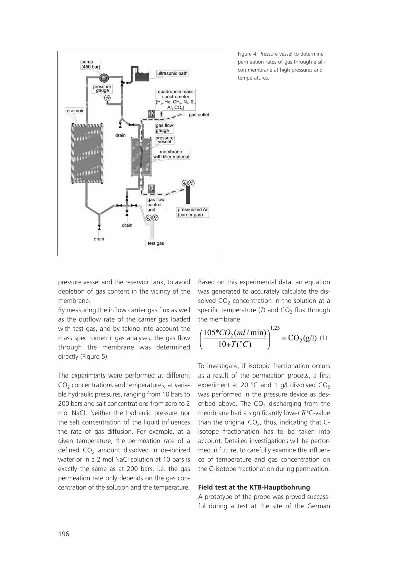
196
pressure vessel and the reservoir tank, to avoiddepletion of gas content in the vicinity of themembrane. By measuring the inflow carrier gas flux as wellas the outflow rate of the carrier gas loadedwith test gas, and by taking into account themass spectrometric gas analyses, the gas flowthrough the membrane was determineddirectly (Figure 5).
The experiments were performed at differentCO2 concentrations and temperatures, at varia-ble hydraulic pressures, ranging from 10 bars to200 bars and salt concentrations from zero to 2mol NaCl. Neither the hydraulic pressure northe salt concentration of the liquid influencesthe rate of gas diffusion. For example, at agiven temperature, the permeation rate of adefined CO2 amount dissolved in de-ionizedwater or in a 2 mol NaCl solution at 10 bars isexactly the same as at 200 bars, i.e. the gaspermeation rate only depends on the gas con-centration of the solution and the temperature.
Based on this experimental data, an equationwas generated to accurately calculate the dis-solved CO2 concentration in the solution at aspecific temperature (T) and CO2 flux throughthe membrane.
(1)
To investigate, if isotopic fractionation occursas a result of the permeation process, a firstexperiment at 20 °C and 1 g/l dissolved CO2
was performed in the pressure device as des-cribed above. The CO2 discharging from themembrane had a significantly lower δ13C-valuethan the original CO2, thus, indicating that C-isotope fractionation has to be taken intoaccount. Detailed investigations will be perfor-med in future, to carefully examine the influen-ce of temperature and gas concentration onthe C-isotope fractionation during permeation.
Field test at the KTB-HauptbohrungA prototype of the probe was proved success-ful during a test at the site of the German
Figure 4: Pressure vessel to determine
permeation rates of gas through a sili-
con membrane at high pressures and
temperatures.
SR09_FGS07.qxd 25.05.2007 14:43 Uhr Seite 196

197
Continental Scientific Drilling Program, KTB(http://icdp.gfz-potsdam.de/sites/ktb/index/index.html). The GMS was lowered to a depthof 860 m into the KTB main drill hole and leftthere for 16 hours. The hydrostatic pressureat depth was 87,94 bars and the temperatu-re 29,6°C. The argon carrier flow was adju-sted to 10 ml/min and the composition of thereturning gas was continuous analyzed with aquadrupole mass spectrometer (Table 1).
By inserting the carbon dioxide flux of0,00058 ml/min and the temperature of29.6°C into equation 1, the CO2 concentra-tion in the formation fluid was calculated to0,3 mg/l. Despite the relative low concentra-tions, this result is in good agreement withdissolved CO2 concentrations of 0.47 mg/ldetermined at a long term pumping test inthe KTB pilot hole (4000 m) and from fluidssampled in the KTB-HB at depths between
3063 and 6031 m (Erzinger & Stober 2005).
In order to allow for the universal employmentof this successfully tested tool in the future,the determination of gas permeation rates isplanned for gases often encountered in natu-ral formation fluids like nitrogen, methane andhelium, and for krypton, which shall be used asa tracer in the CO2SINK project.
Figure 5: CO2 flux permeating through a 1 m silicone tubing (polydimethylsiloxan) of
an outer diameter of 6.4 mm and a wall thickness of 0.8 mm. Measurements where
performed in a temperature range between 20°C to 60°C and dissolved carbon dioxide
concentration between 0.5 and 4 g/l. Hydrostatic pressure was adjusted to 80 bar.
Table 1: Composition of the returning gas in the KTB-HB.
Ar = 98,2vol%CO2 = 58 ppmvH2 = 1090 ppmvO2 = 15 ppmvN2 = 1,09 vol%He = 210 ppmvCH4 = 5540 ppmv
SR09_FGS07.qxd 25.05.2007 14:43 Uhr Seite 197

198
ConclusionThe GMS system allows the online determina-tion of the dissolved gases in bore hole fluids.In addition, the system can be employed,under extreme pressure conditions, for the col-lection of gas samples for further detailed inve-stigations in laboratory, however special atten-tion must be given to isotope fractionation.
The restrictions of conventional techniques, inparticular with regard to the discontinuousoperation are avoided. The system is thereforesuitable for long term investigations and todirectly monitor changes of CO2 and other gasconcentrations at depth, i.e. the GMS is a toolsfor cost-effective gas monitoring and can assistthe installation of an industrial real-time CO2
monitoring network to be used during activestorage of CO2 in geological formations.
LiteratureBeckmann, W., & Seider, M., H., (1967):Gasdurchlässigkeit von gummiartigen Werk-stoffen für Stickstoff. Kolloid-Zeitschrift & Zeit-schrift für Polymere, Band 220, Heft 2, 97-107.
Bruant, jr., R., G., Celia, M. A., Guswa, A. J.and Peters, C., A., (2002): Safe storage of CO2
in deep saline aquifers, Environ. Sci. Technol.36, 240A-245A.
Erzinger, J., & Stober, I. (2005): Introduction toa Special Issue: long-term fluid production inthe KTB pilot hole Germany. Geofluids 5, 1-7.
Kesson, J., (1984): The Diffusion of GasesThrough a Silicon Rubber Membrane, and Itsapplication to an In-Line Carbonation Meter.MBAA Technical Quarterly, Vol. 21, No.3,143-146.
Novodirect, GmbH (2006): Fisher BioblockScientific, 1008 p.
Ploetz, C., (2003): Sequestrierung von CO2:Technologien, Potenziale, Kosten und Umwelt-auswirkungen. Externe Expertise für dasWBGU-Hauptgutachten 2003 »Welt im Wan-del: Energiewende zur Nachhaltigkeit«, Berlin,Heidelberg, New York: Springer Verlag,1-23.
Wilson E.J. Johnson, T. L., Keith, D.W. (2003):Regulating the ultimate sink: managing therisks of geological CO2 storage, Environ. Sci.Technol. 37, 3476 – 3483.
SR09_FGS07.qxd 25.05.2007 14:43 Uhr Seite 198

199
SR09_FGS07.qxd 25.05.2007 14:43 Uhr Seite 199

Author’s Index
200
AAimard , N. . . . . . . . . . . . . . . . . . . . . 1Alles S.. . . . . . . . . . . . . . . . . . . . . . 191André L. . . . . . . . . . . . . . . . 2, 18, 140Asmus S. . . . . . . . . . . . . . . . . . . . . . . 3Audigane P. . . . . . . . . . . . . . . . 18, 131Azaroual M . . . . 2, 140, 141, 188, 189
BBachaud P. . . . . . . . . . . . . . . . . . . . . 4Back M. . . . . . . . . . . . . . . . . . . . . . . 5Balthasar K. . . . . . . . . . . . . . . . . . . . . 6Barlet-Gouédard V. . . . . . . . . . . 14, 39Barrès O. . . . . . . . . . . . . . . . . . . . . . 85Battaglia-Brunet F. . . . . . . . . . . . . . 150Battani A. . . . . . . . . . . . . . . . . . . . 112Becquey M. . . . . . . . . . . . . . . . . . 8, 69Behra .. . . . . . . . . . . . . . . . . . . . . . . 50Bénézeth P. . . . . . . . . . . 14, 16, 47, 82Beny C. . . . . . . . . . . . . . . . . . . . . . 185Bernard D. . . . . . . . . . . . . . . . . . 14, 82Berne P. . . . . . . . . . . . . . . . . . . . . . . . 4Bildstein O. . . . . . . . . . . . . . . 131, 166Blaisonneau A.. . . . . . . . . . . . . . . . . 18Blanchet D. . . . . . . . . . . . . . . . . . . 150Bonijoly D. . . . . . . . . . . . . . . . . . . . 36Borm G. . . . . . . . . . . . . . . . . . . . . . 19Bouc O. . . . . . . . . . . . . . . . . . . . . . 27Broseta D. . . . . . . . . . . . . . . . 141, 166Brosse E. . . . . . . . . . . . . . . . 14, 36, 99Bruneau J. . . . . . . . . . . . . . . . . . . . . . 8Brunet F. . . . . . . . . . . . . . . . . . . . . . 39Busch A. . . . . . . . . . . . . . . . . 120, 191Buske S.. . . . . . . . . . . . . . . . . . . . . 181Bychkov A.Y. . . . . . . . . . . . . . . . . . . 47
CCailteau C.. . . . . . . . . . . . . . . . . . . . 85Carles P. . . . . . . . . . . . . . . . . . . . . . . 49Charrière D. . . . . . . . . . . . . . . . . . . . 50Chiquet P. . . . . . . . . . . . . . . . . . . . 166 Class H. . . . . . . . . . . . . . . . . . . . . . . 51Clauser C. . . . . . . . . . . . . . . . . . . . . 59Corvisier J. . . . . . . . . . . . . . . . . . . . 39
DDandurand J.L.. . . . . . . . . . . . . . . . . 16De Donato P. . . . . . . . . . . . . . . . . . . 85De Gennaro . . . . . . . . . . . . . . . . . . 14Delay J. . . . . . . . . . . . . . . . . . . . . . 166Delmas J. . . . . . . . . . . . . . . . . . . . . . 99Delorme F. . . . . . . . . . . . . . . . . . . . 150Didier C. . . . . . . . . . . . . . . . . . . . . . 50Dietrich M . . . . . . . . . . . . . . . . . . . . . 8Dromart G . . . . . . . . . . . . . . . . . . . 150Dupraz S . . . . . . . . . . . . . . . . . . . . 150
EEbigbo A.. . . . . . . . . . . . . . . . . . . . . 51Egermann P.. . . . . . . . . . . . 2, 140, 141Ehinger S . . . . . . . . . . . . . . . . . . 68, 89Emmanuel L.. . . . . . . . . . . . . . . . . 112Erzinger J. . . . . . . . . . . . . . . . . . . . 192
FFabbri A. . . . . . . . . . . . . . . . . . . . . . 39Fabriol H. . . . . . . . . . . . . . . . . . . . . . 69Fleury M. . . . . . . . . . . . . . . . . . . . . . 72Florette M.. . . . . . . . . . . . . . . . . . . . 73Flukiger F. . . . . . . . . . . . . . . . . . . . . 82Fourar M.. . . . . . . . . . . . . . . . . . . . 113
SR09_FGS07.qxd 25.05.2007 14:43 Uhr Seite 200

GGarcia B. . . . . . . . . . . . . . . . . . . . . 150Garcia D. . . . . . . . . . . . . . . . . . . 14, 36 Garnier C. . . . . . . . . . . . . . . . . . . . . 85Gaucher E.C. . . . . . . . . . . . . . . . . . . 87Gehin A. . . . . . . . . . . . . . . . . . . . . 178Gérard E. . . . . . . . . . . . . . . . . . . . . 140Goffé B. . . . . . . . . . . . . . . . . . . . . . . 39Golubev S. . . . . . . . . . . . . . . . . . . . . 16Golubev S.V. . . . . . . . . . . . . . . . . . 179Gouze P. . . . . . . . . . . . . . . . . . . . . . 14Grgic D. . . . . . . . . . . . . . . . . . . . . . 183Gudehus G. . . . . . . . . . . . . . . . . . . . . 6Guyot F. . . . . . . . . . . . . . . . . . . . . . 150
HHaeseler F. . . . . . . . . . . . . . . . . . . . 150Hasanov V. . . . . . . . . . . . . . . . . . . . . 36Hauser-Fuhlberg M. . . . . . . . . . . . . . . 6Homand F. . . . . . . . . . . . . . . . . . . . 183Hoth N. . . . . . . . . . . . . . . . . . . . 68, 89Houel P. . . . . . . . . . . . . . . . . . . . . . . 99Hubert G. . . . . . . . . . . . . . . . 166, 178Huc A.-Y. . . . . . . . . . . . . . . . . . . . . 150Huguet F. . . . . . . . . . . . . . . . . . . . 8, 69
IIgnatiadis I. . . . . . . . . . . . . . . . . . . 150
JJammes L. . . . . . . . . . . . . . . . . . . . 100Jeandel E. . . . . . . . . . . . . . . . . . . . 112Jordan G. . . . . . . . . . . . . . . . . . . . . 179Jullien M. . . . . . . . . . . . . . . . . 150, 166
KKacem M. . . . . . . . . . . . . . . . . . . . 113Kassahun A.. . . . . . . . . . . . . . . . . . . 89Kervévan C . . . . . . . . . . . . . . . . . . . . 2Kopp A. . . . . . . . . . . . . . . . . . . . . . . 50Kosel D. . . . . . . . . . . . . . . . . . . . . . 114Krooss B. M. . . . . . . . . . . . . . 120, 191Kühn M. . . . . . . . . . . . . . . . . . . . 5, 59
LLachet V. . . . . . . . . . . . . . . . . . . . . 189Lagneau V.. . . . . . . . . . . 131, 166, 189Lau S. . . . . . . . . . . . . . . . . . . . . . . 130Le Gallo Y. . . . . . . . . . . . . . . . . . . . 131Le Gouevec J.. . . . . . . . . . . . . . . . . . 27Le Nindre Y.-M. . . . . . . . . . . . . . . . 185Lerouge C. . . . . . . . . . . . . . . . . . . . 185Lescanne M. 14, 36, 69, 141, 185, 189Libert M. . . . . . . . . . . . . . . . . . . . . 150Lions J.. . . . . . . . . . . . . . . . . . . . . . 140Löhmannsröben H.-G. . . . . . . . . . . 130Lombard J.M. . . . . . . 2, 113, 140, 141
MMagot M. . . . . . . . . . . . . . . . . . . . 150Mann J. . . . . . . . . . . . . . . . . . . . . . 181May F. . . . . . . . . . . . . . . . . . . . . . . 143Ménez B. . . . . . . . . . . . . . . . . . 14, 150Menjoz. A . . . . . . . . . . . . . . . . . . . . . 2Meunier J. . . . . . . . . . . . . . . . . . . . . . 8Michel C. . . . . . . . . . . . . . . . . . . . . 150Mugler C. . . . . . . . . . . . . . . . . . . . 131Mugler E.. . . . . . . . . . . . . . . . . . . . 131Munier G. . . . . . . . . . . . . 36, 141, 164Muschalle T.. . . . . . . . . . . . . . . . . . . 89Mutschler T. . . . . . . . . . . . . . . . . . . . . 6
Author’s Index
201
SR09_FGS07.qxd 25.05.2007 14:43 Uhr Seite 201

202
Author’s Index
OOger P. . . . . . . . . . . . . . . . . . . . . . . 150Ollivier B. . . . . . . . . . . . . . . . . . . . . 150Orghici R. . . . . . . . . . . . . . . . . . . . . 165
PPeiffer S. . . . . . . . . . . . . . . . . . . . . . . . 5Perfetti E. . . . . . . . . . . . . . . . . . . . . 178Pironon J. . . . . . . 69, 85, 141, 166, 178Pokrovsky O. S. . . . . . . . . . . . . . 47, 179Pokryszka Z. . . . . . . . . . . . . . . . . 50, 69Porcherie O. . . . . . . . . . . . . . . . . . . . 39Pruessmann J. . . . . . . . . . . . . . . . . . 181
QQuisel N. . . . . . . . . . . . . . . . . . . . . . 27
RRadilla G. . . . . . . . . . . . . . . . . . . . . 113Ramboz C.. . . . . . . . . . . . . . . . . . . 185Rasolofosaon P. . . . . . . . . . . . . . . . . . 8Rémond F. . . . . . . . . . . . . . . . . . . . 183Renard F. . . . . . . . . . . . . . . . . . . . . . 14Rigollet C. . . . . . . . . . . . . . 14, 36, 141Rimmelé G. . . . . . . . . . . . . . . . . . . . 39Rommevaux-Jestin C.. . . . . . . . . . . 150Rübel S. . . . . . . . . . . . . . . . . . . . . . . . 6Rubert Y. . . . . . . . . . . . . . . . . . . . . 185Rückheim J. . . . . . . . . . . . . . . . . . . . 73
SSalffner K.. . . . . . . . . . . . . . . . . . . . 130Sarda P. . . . . . . . . . . . . . . . . . . . . . . 112Sausse J. . . . . . . . . . . . . . . . . . . . . . 178Sbai M. A . . . . . . . . . . . . . . . . . . . . 188Schade W.. . . . . . . . . . . . . . . . . . . . 165Schilling F. . . . . . . . . . . . . . . . . . . . . 19Schlömann M. . . . . . . . . . . . . . . 68, 89Schott J. . . . . . . . . . . . . . . . . . . . 16, 47Schubnel A. . . . . . . . . . . . . . . . . . . . 39Seifert J. . . . . . . . . . . . . . . . . . . . 68, 89Sterpenich J. . . . . . . . . . . . . . . 178, 189
TThielemann T. . . . . . . . . . . . . . . . . . . . 3Thoraval A. . . . . . . . . . . . . . . . . 36, 190Tocqué E. . . . . . . . . . . . . . . . . . . . . 112Trenty L. . . . . . . . . . . . . . . . . . . . . . 131Triantafyllidis T. . . . . . . . . . . . . . . . . . . 6
VVidal-Gilbert S. . . . . . . . . . . . . . . 8, 190Vinsot A.. . . . . . . . . . . . . . . . . . . . . 166Voigtlander G. . . . . . . . . . . . . . . . . . 73Vu Hoang D. . . . . . . . . . . . . . . . . . . . 69
WWeidler P. . . . . . . . . . . . . . . . . . . . . . . 6Wendel H.. . . . . . . . . . . . . . . . . . . . . 73Willer U. . . . . . . . . . . . . . . . . . . . . . 165Wollenweber J. . . . . . . . . . . . . . . . . 191
ZZimmer M. . . . . . . . . . . . . . . . . . . . 192
SR09_FGS07.qxd 25.05.2007 14:43 Uhr Seite 202

203
Notes
SR09_FGS07.qxd 25.05.2007 14:43 Uhr Seite 203

204
Notes
SR09_FGS07.qxd 25.05.2007 14:43 Uhr Seite 204

1. French-German Symposium onGeological Storage of CO2
June 21./22., 2007GeoForschungsZentrum Potsdam
Abstracts
GEOTECHNOLOGIENScience Report
No. 9
1. French-German Symposium on Geological Storage of CO2
ISSN: 1619-7399
National R&D programmes on CO2 storage exist both in France and Germany. In France, theAgence Nationale de la Recherche (ANR) launched a CO2 programme in 2005. In Germany, theFederal Ministry of Education and Research (BMBF) launched research projects on CO2 storage inthe same year, as part of the R&D programme GEOTECHNOLOGIEN. The prime aim of the firstFrench-German Symposium is to bring together specialists on CO2 storage in order to increase thejointly held knowledge of CO2 storage R&D activities in both countries. A further objective of thesymposium is to initiate bi-lateral projects between the various research groups to enable benefitto be obtained from synergies of the expertise and skills available in the two countries.
The GEOTECHNOLOGIEN programme is funded by the Federal Ministry for
Education and Research (BMBF) and the German Research Council (DFG)
No.
91.
Fren
ch-G
erm
anSy
mpo
sium
onG
eolo
gica
lSto
rage
ofCO
2G
EOTE
CHN
OLO
GIE
NSc
ienc
eRe
port
Umschlag_SR09.qxd 25.05.2007 14:15 Uhr Seite 1


![Building science report [malaysia]](https://img.dokumen.tips/doc/110x75/555c909cd8b42a85758b4a5f/building-science-report-malaysia.jpg)
![Building science report [singapore]](https://img.dokumen.tips/doc/110x75/555c9099d8b42a85758b4a5d/building-science-report-singapore.jpg)