Embed Size (px)
Citation preview

NGE-TFT Project # 5139-18
GEOTECHNICAL ENGINEERING REPORT for the proposed
COOK INLET HOUSING AUTHORITY OLD SEWARD SENIOR HOUSING PROJECT
ANCHORAGE, ALASKA
Prepared for: Spark Design, LLC
5401 Cordova Street, Suite 301 Anchorage, AK 99518
Prepared by:
Northern Geotechnical Engineering, Inc. d.b.a. Terra Firma Testing
OCTOBER 2018

Page 1 of 1
11301 Olive Lane Anchorage, Alaska 99515 · Phone: (907) 344-5934 · Fax: (907) 344-5993 · Website: www.nge-tft.com
October 30, 2018 NGE-TFT Project # 5139-18 Spark Design, LLC 5401 Cordova Street, Suite 301 Anchorage, AK 99518 Attn: Deanna Wlad, AIA - Architect RE: GEOTECHNICAL ENGINEERING ASSESSMENT OF THE PROPOSED COOK
INLET HOUSING AUTHORITY OLD SEWARD SENIOR HOUSING PROJECT TO BE CONSTRUCTED AT LOT 4 OF THE RECYCLED PROPERTIES SUBDIVISION, ANCHORAGE, ALASKA.
Deanna,
We (Northern Geotechnical Engineering, Inc. d.b.a. Terra Firma Testing) have completed a geotechnical engineering assessment of the aforementioned project. Our assessment suggests that the undisturbed, native glacial till deposits which underlie the project site are suitable for supporting the proposed improvements provided that proper engineering controls are incorporated in to the design and construction of the proposed site improvements. However, the southwestern portion of the project site is overlain by varying amounts of non-structural fill that is not suitable for foundation support and will need to be removed from the footprint of the proposed building prior to foundation construction.
In the following report we provide a summary of our field and laboratory programs, as well as provide our conclusions regarding the suitability of the project site to support the proposed site improvements and our recommendations for the design and construction of the proposed site improvements.
We greatly appreciate the opportunity to provide you with our professional service. Please contact us directly with any questions or comments you may have regarding the information that we present in this report, or if you have any other questions, comments, and/or requests.
Sincerely, Northern Geotechnical Engineering, Inc. d.b.a. Terra Firma Testing
Eva X. Ge, P.E. Keith F. Mobley, P.E. Project Engineer President

Geotechnical Engineering Report NGE-TFT Project #5139-18 CIHA Old Seward Senior Housing – Anchorage, AK Spark Design, LLC October 30, 2018
Page i of ii
11301 Olive Lane Anchorage, Alaska 99515 · Phone: (907) 344-5934 · Fax: (907) 344-5993 · Website: www.nge-tft.com
Table of Contents 1.0 INTRODUCTION ...............................................................................................................1 2.0 PROJECT OVERVIEW ......................................................................................................1 3.0 PREVIOUS PROJECT SITE ACTIVITIES ........................................................................2 4.0 CURRENT PROJECT SITE ACTIVITIES.........................................................................2
4.1 Subsurface Exploration .....................................................................................................2 4.2 Groundwater Level Monitoring ........................................................................................3
5.0 LABORATORY TESTING.................................................................................................3 6.0 DESCRIPTION OF SUBSURFACE CONDITIONS .........................................................4
6.1 General Subsurface Profile ................................................................................................4 6.2 Groundwater ......................................................................................................................5 6.3 Frozen Soils .......................................................................................................................5
7.0 ENGINEERING CONCLUSIONS .....................................................................................5 7.1 General Site Conclusions ..................................................................................................5 7.2 Earthworks ........................................................................................................................5 7.3 Foundations .......................................................................................................................6 7.4 Underground Utilities ........................................................................................................6 7.5 Pavement ...........................................................................................................................6 7.6 Settlements ........................................................................................................................6 7.7 Seismic Design Parameters ...............................................................................................7
8.0 DESIGN RECOMMENDATIONS .....................................................................................7 8.1 Earthworks ........................................................................................................................7 8.2 Shallow Foundations .........................................................................................................8
8.2.1 Soil Bearing Capacity ................................................................................................8 8.2.2 Continuous Strip Footings and Spread Footings .......................................................8 8.2.3 Thickened Edge Slab Foundations and Floor Slabs ..................................................9 8.2.4 Footing Uplift...........................................................................................................10 8.2.5 Foundation Insulation ..............................................................................................10 8.2.6 Cold (Unheated) Shallow Foundations ....................................................................11 8.2.7 Lateral Loads for Foundation and Retaining Walls .................................................12
8.3 Underground Utilities ......................................................................................................13 8.4 Pavement Sections ...........................................................................................................14 8.5 Surface Drainage .............................................................................................................16
9.0 CONSTRUCTION RECOMMENDATIONS ...................................................................16 9.1 Earthwork ........................................................................................................................16 9.2 Heated Shallow Foundations ...........................................................................................17 9.3 Cold (Unheated) Shallow Foundations ...........................................................................17 9.4 Underground Utilities ......................................................................................................18 9.5 Pavement .........................................................................................................................18 9.6 Insulation .........................................................................................................................18 9.7 Winter Construction ........................................................................................................18
10.0 THE OBSERVATIONAL METHOD ...............................................................................19 11.0 CLOSURE .........................................................................................................................20

Geotechnical Engineering Report NGE-TFT Project #5139-18 CIHA Old Seward Senior Housing – Anchorage, AK Spark Design, LLC October 30, 2018
Page ii of ii
11301 Olive Lane Anchorage, Alaska 99515 · Phone: (907) 344-5934 · Fax: (907) 344-5993 · Website: www.nge-tft.com
List of Figures
Figure 1 ................................................................................................... Project Site Location Map Figure 2 .................................................... Current Surface Topography and Exploration Locations Figure 3 ........................................................................................................... Proposed Site Layout Figure 4 ...................................................................................................... Blow Count Corrections Figure 5 ........................................................................................ Footing Uplift Capacity Diagram Figure 6 ................................................................ Uninsulated Shallow Foundation Configurations Figure 7 ..................................................................... Insulated Shallow Foundation Configurations Figure 8 ....................................................................... Lateral Retaining Wall Pressure Schematics Figure 9 .............................................................................................. MOA Material Specifications
List of Tables
Table 1: Equivalent Fluid Specific Weight for Lateral Loading Design ...................................... 13 Table 2: Recommended Uninsulated Pavement Section .............................................................. 15 Table 3: Type B, Class 1 Geotextile Fabric Strengths .................................................................. 15
List of Appendices
Appendix A .................................. Graphical Borehole Logs and Split-Spoon Sample Photographs Appendix B ................................................................................................. Laboratory Test Results Appendix C .................................................................... USGS Seismic Site Classification Reports

Page 1 of 21
11301 Olive Lane Anchorage, Alaska 99515 · Phone: (907) 344-5934 · Fax: (907) 344-5993 · Website: www.nge-tft.com
1.0 INTRODUCTION In this report, we (Northern Geotechnical Engineering, Inc. d.b.a. Terra Firma Testing) present the results of a geotechnical assessment that we conducted at Lot 4 of the Recycled Properties Subdivision, Anchorage, Alaska; hereafter referred to as “the project site”. We provided our professional service in accordance with our service fee proposal #18-145 which we submitted to Spark Design, LLC (SPARK) on July 24, 2018. SPARK approved our proposed scope of service on September 17, 2018 via signature of the authorization page contained within fee proposal #18-145.
SPARK contracted us to characterize the subsurface conditions across the project site in an effort to assess the suitability of the subgrade to support the proposed three-story senior housing facility which is to be constructed at the project site and to develop general geotechnical engineering recommendations for the proposed site improvements.
In this report, we provide a summary of our field and laboratory testing efforts, as well as provide our conclusions and recommendations regarding the design and construction of the proposed site improvements.
2.0 PROJECT OVERVIEW As we detail in Figure 1 of this report, the project site is located along the southwest side of the Old Seward Highway, just south of its intersection with Dare Avenue, in Anchorage, Alaska. The legal description of the project site (as we understand it to be) is Lot 4 of the Recycled Properties Subdivision, Anchorage, Alaska.
The project site is approximately two acres in area. The majority of the project site is relatively flat, with the southwestern edge sloping downwards in an approximately 2.2H:1V slope (approximately 22 feet vertical drop in total). We have included a recent topographic survey of the project site in Figure 2 of this report.
Proposed improvements to the project site include the construction of a three-story, multi-unit senior housing facility and associated utilities and paved parking areas/driveways. We present the proposed site layout in Figure 3 of this report. The current 35% drawings developed by SPARK (dated October 11, 2018) indicate that the proposed facility will be above grade, without any basement or subgrade levels.
The project site, and adjacent Lots 1 - 3 of the Recycled Subdivision (to the north), are all part of the former Laborers’ Union Local 341 Training complex, which has since been vacated. The project site was used for materials/equipment storage and for apprenticeship training; which included earthworks training exercises (mock underground utility installation, equipment handling, etc.). As such, we expect that some of the surficial soils on-site have been disturbed.

Geotechnical Engineering Report NGE-TFT Project #5139-18 CIHA Old Seward Senior Housing – Anchorage, AK Spark Design, LLC October 30, 2018
Page 2 of 21
11301 Olive Lane Anchorage, Alaska 99515 · Phone: (907) 344-5934 · Fax: (907) 344-5993 · Website: www.nge-tft.com
3.0 PREVIOUS PROJECT SITE ACTIVITIES We conducted a limited subsurface exploration program at the project site in July 2017 (in support of a previous site development concept) during which time we oversaw the advancement of two soil borings, designated as B1 and B2, along the crest of the existing slope (which parallels the southwest property line). We present the approximate borehole locations in Figure 2 of this report, and graphical borehole logs in Appendix A of this report. Details of our 2017 exploration effort can be found in our geotechnical letter entitled “Subsurface Exploration Findings for Lot 4 of the Recycled Properties Subdivision in Anchorage, Alaska” which we submitted to Cook Inlet Housing Authority on July 6, 2017.
Our exploration effort confirmed that this portion of the project site is overlain with approximately 6 to 8 feet of fill. The fill is generally granular in composition, contains trace percentages of mixed organic debris, and is (at least partially) underlain by a layer of peat approximately 2 to 3 feet in thickness. Penetration test information that we collected during our exploration effort suggest that the fill may be variably consolidated.
4.0 CURRENT PROJECT SITE ACTIVITIES 4.1 Subsurface Exploration
We conceived, coordinated, and directed a subsurface exploration program at the project site in an effort to further characterize the subsurface conditions of the project site as they currently exist. We subcontracted Discovery Drilling, Inc. (DDI) to provide the necessary geotechnical exploration services. A qualified representative from our office was present on-site during the entire exploration program to select the exploration locations, direct the exploration activities, log the geology of each exploration, and collect representative samples for further identification and laboratory analysis. Under our direction, DDI advanced a total of seven additional soil borings, designated as B3 to B9, at the project site on October 3, 2018 to depths ranging from approximately 16.5 to 31.5 feet below the existing ground surface (bgs). We present the approximate borehole locations on Figure 2 of this report.
Under our direction, DDI performed a Modified Penetration Test (MPT) at regular intervals during the drilling of each borehole. A MPT can be used to assess the consistency of a soil interval and to collect representative soil samples. A MPT is performed by driving a 3.0-inch O.D. (2.4-inch I.D.) split-spoon sampler at least 18 inches past the bottom of the advancing augers with blows from a 340-lb drop-hammer, free-falling 30 inches onto an anvil attached to the top of the drill rod stem. Our field representative recorded the hammer blows required to drive the modified split-spoon sampler the entire length of each sample interval, or until sampler refusal was encountered. We have provided the field blow count data for each sample interval (in six-inch increments) on the graphical borehole logs contained in Appendix A of this report.

Geotechnical Engineering Report NGE-TFT Project #5139-18 CIHA Old Seward Senior Housing – Anchorage, AK Spark Design, LLC October 30, 2018
Page 3 of 21
11301 Olive Lane Anchorage, Alaska 99515 · Phone: (907) 344-5934 · Fax: (907) 344-5993 · Website: www.nge-tft.com
We corrected the field blow count data for all seven boreholes for standard confining pressure, drill rod length, and drop-hammer operation procedure to estimate a standard (N1)60 value for each sample interval. (N1)60 values are a measure of the relative density (compactness) and consistency (stiffness) of cohesionless or cohesive soils, respectively. Our estimate of the (N1)60 values is based on the drop-hammer blows required to drive the spilt-spoon sampler the final 12-inches of an 18-inch MPT. We have provided our estimated (N1)60 values for each sample interval on the graphical borehole logs contained in Appendix A of this report. The automatic drop-hammer that DDI used for this project is not standard, so we applied a correction factor of 1.1 to the (N1)60 values to account for the efficiency of the automatic drop-hammer used. We have provided a graphical plot of the field blow count corrections that we used to correct for confining pressure and drill rod length in Figure 3 of this report.
Our field representative photographed each split-spoon sample that they collected during our exploration program and we have included these photographs in Appendix A of this report. Our field representative sealed each sample that they collected during our subsurface exploration program inside of an air-tight bag, to help preserve the moisture content of each sample, and then submitted each sample to our laboratory for further identification and analysis.
We directed DDI to install one-inch diameter, open-ended PVC pipes from the ground surface down to the bottom of boreholes B3, B5 and B9 to serve as conduits (i.e., monitoring wells) for future groundwater level monitoring. As per our instruction, DDI hand-slotted the bottom 6.5 to 15 feet of the monitoring well casings prior to installation and then backfilled the annulus of each monitoring well borehole with prescribed amounts of drill cuttings and then hydrated the bentonite chips (to form a seal against surface water infiltration). We have included construction diagrams for each groundwater monitoring well on the graphical borehole logs contained in Appendix A of this report.
4.2 Groundwater Level Monitoring
We conducted groundwater level monitoring efforts at the project site on October 4, 2018 to help determine the static groundwater level. We used an electronic water level meter (with 0.01-foot increments) to measure the relative depth of the groundwater surface (below the existing ground surface) at each monitoring well location. We did not observe groundwater in any of the three monitoring wells.
5.0 LABORATORY TESTING We collected a total of 59 soil samples from all nine boreholes that DDI advanced at the project site and submitted all of the soil samples to our laboratory for further identification and geotechnical analysis. We tested select soil samples in accordance with the respective ASTM standard test methods including:

Geotechnical Engineering Report NGE-TFT Project #5139-18 CIHA Old Seward Senior Housing – Anchorage, AK Spark Design, LLC October 30, 2018
Page 4 of 21
11301 Olive Lane Anchorage, Alaska 99515 · Phone: (907) 344-5934 · Fax: (907) 344-5993 · Website: www.nge-tft.com
moisture content analysis (ASTM D-2216);
determination of fines content (a.k.a. P200 – ASTM D-1140);
grain size sieve and hydrometer analysis (ASTM D-6913 & D-422); and
organic content (ASTM D2974).
It is important to note that ASTM test method D-6913 requires that any soil sample specimen which is to be submitted for gradational analysis (by ASTM D-422 or other methods) must satisfy a minimum mass requirement based on the maximum particle size of the sample specimen. Split-spoon sampling techniques (standard or modified), as well as other small-diameter soil sampling techniques (e.g., macro-core, etc.), typically recover anywhere from approximately 1 to 10 pounds of sample specimen. The amount of sample specimen recovered can be influenced by (amongst other variables) the soil gradation, soil density, sample interval, sampler tooling, and soil moisture content. As a result, samples of coarse-grained soils (with individual soil particles greater than approximately 0.75 inches in diameter) collected with small-diameter sampling methods (e.g., split-spoons, macro-core, etc.) may not meet the minimum mass requirement specified by Table 2 of ASTM D-6913. This may result in inaccurate gradational and frost classification results. The use of small-diameter sampling devices in coarse-grained soils (e.g., sand and gravel) can result in the collection of unrepresentative samples due to: the exclusion of oversized particles (larger than the opening of the sampler) from the sample; and the mechanical breakdown/degradation of coarse-grained particles by the sampling process (producing an unrepresentative increase in smaller-diameter particles in the sample). Both of these sampling biases can skew laboratory test results towards the fine-grained end of the gradational spectrum.
The laboratory test results, along with the observations we made during our subsurface exploration efforts, aid in our evaluation of the subsurface conditions at the project site and help us to assess the suitability of the subsurface materials located at the project site to support the proposed improvements. We have included the results of our geotechnical laboratory analyses on the graphical exploration logs contained in Appendix A of this report and on the laboratory data sheets contained in Appendix B of this report.
6.0 DESCRIPTION OF SUBSURFACE CONDITIONS We compiled our field observations with the results from our laboratory analyses to produce graphical logs of each subsurface exploration (Appendix A). The graphical exploration logs depict the subsurface conditions that we identified at each exploration location and help us to interpret/extrapolate the subsurface conditions for areas adjacent to, and immediately surrounding, each exploration location across the project site.
6.1 General Subsurface Profile
The majority of the project site, excluding area surrounding B8, is overlain by approximately 2 to 9 feet of non-structural fill, which is not generally suitable for foundation and/or floor slab support. The thickest amounts of fill appear to be located along the southern and southwestern portions of

Geotechnical Engineering Report NGE-TFT Project #5139-18 CIHA Old Seward Senior Housing – Anchorage, AK Spark Design, LLC October 30, 2018
Page 5 of 21
11301 Olive Lane Anchorage, Alaska 99515 · Phone: (907) 344-5934 · Fax: (907) 344-5993 · Website: www.nge-tft.com
the project site. There are also several moderate-sized stockpiles of non-structural fill, concrete debris, etc. (generally less than approximately 20-30 yds in volume) located at various locations across the project site.
In B2, the non-structural fill material is underlain by a three-foot thick layer of peat, which does not appear to be laterally continuous across the project site and may also be fill. The entire project site is subsequently underlain by massive deposits of dense silty sand with gravel which are consistent with local glacial till deposits and extend to depths of at least 31 feet bgs.
6.2 Groundwater
We did not encounter groundwater during either of our subsurface exploration programs (2017 & 2018), or during our groundwater monitoring efforts on October 4, 2018. We do not expect groundwater to occur above depths of 30 feet bgs across the project site, and we do not expect groundwater to impact any foundation and/or underground utility excavations.
6.3 Frozen Soils
We did not observe any indications of frozen soils during our subsurface exploration program and we do not expect permafrost to occur anywhere across the project site.
7.0 ENGINEERING CONCLUSIONS 7.1 General Site Conclusions
Based on the findings of our field and laboratory testing efforts, it is our conclusion that the undisturbed, native dense glacial till deposits which we observed across the project site are generally suitable to support the proposed improvements; provided that our concerns and recommendations that we present in this report are addressed by the design and construction processes.
7.2 Earthworks
The existing fill and/or organic material that we observed at the project site is unsuitable for supporting shallow foundations and gravity-fed utilities as differential settlements will likely occur as loads are applied (due to the uncertainty of the compactness of the existing fill and/or the presence of compressible organic debris). Any existing fill and/or organic soils which is located within the footprint of any foundations or gravity utilities will need to be completely removed and be replaced with properly placed structural fill to achieve the planned footing/utility grade.
Any of the existing fill material which is excavated from the project site can be re-used as structural fill on-site as long as they are free of any organic materials and are placed using proper placement and compaction techniques. The existing silt-rich fill material, however should not be re-used as structural fill in any areas which will be subjected to freezing temperatures during winter months;

Geotechnical Engineering Report NGE-TFT Project #5139-18 CIHA Old Seward Senior Housing – Anchorage, AK Spark Design, LLC October 30, 2018
Page 6 of 21
11301 Olive Lane Anchorage, Alaska 99515 · Phone: (907) 344-5934 · Fax: (907) 344-5993 · Website: www.nge-tft.com
as it is susceptible to the formation of ice lenses and frost heaving/jacking forces. We discuss our earthworks recommendations in more detail in Sections 8.1 and 9.1 of this report.
7.3 Foundations
A conventional shallow foundation is suitable to support the proposed building at the project site given the existing fill material is completely removed and replaced with proper placed structural fill. Foundation configurations and minimum burial depths will be a function of the frost susceptibility of the subgrade soils and whether or not the foundation subgrade will be allowed to freeze during winter months. We provide detailed recommendations regarding the design and construction of any shallow foundations at the project site in Sections 8.2, 9.2 and 9.3.
7.4 Underground Utilities
In general, the soils in which deep, gravity-fed utility trenches (6 to 10 feet bgs) are to be constructed likely consist of fill material and/or undisturbed, native silty sand with gravel. The existing fill material may be suitable for supporting buried utilities, as long as the utilities are not susceptible to damage from differential movements. Gravity-fed utilities can be founded directly onto the undisturbed, native glacial till deposits and/or structural fill, assuming proper placement and compaction techniques are employed. We provide more detailed recommendations for underground utility design in Section 8.3 and 9.4 of this report.
7.5 Pavement
Our laboratory testing suggests that the both the fill and native glacial till deposits which occur at the project site classify as F2 to F3 on the Municipality of Anchorage (MOA) frost classification scale. Pavement sections may be designed to “float” above the existing fill assuming proper engineering controls are incorporated into the pavement section design to help reduce the likelihood of differential settlement. We present our pavement section design and construction recommendations in detail in Sections 8.4 and 9.5 of this report.
7.6 Settlements
Settlements for shallow foundations should be within tolerable limits, provided that they are placed directly onto the undisturbed, native glacial till deposits (or properly placed structural fill located directly above the undisturbed, native glacial till deposits). We anticipate a total settlement for shallow concrete foundations placed on either the undisturbed, native glacial till deposits and/or or structural fill placed above the undisturbed, native glacial till deposits (as we discuss in Section 8.2 of this report) to be less than three-quarters (3/4) of an inch, with differential settlements comprising about one-half (1/2) of the total anticipated settlement. Settlement amounts could increase substantially if the structural fill material used to bring any foundation pads to grade is not properly compacted. Most of the settlements should occur as the building loads are applied, such that additional long-term settlements should be relatively small and within tolerable limits.

Geotechnical Engineering Report NGE-TFT Project #5139-18 CIHA Old Seward Senior Housing – Anchorage, AK Spark Design, LLC October 30, 2018
Page 7 of 21
11301 Olive Lane Anchorage, Alaska 99515 · Phone: (907) 344-5934 · Fax: (907) 344-5993 · Website: www.nge-tft.com
Settlements under driveways and parking areas are expected to vary more than under any buildings, especially where utility trenches are located. Proper earthwork is necessary to help reduce the settlement potential. The settlement potential can be reduced by performing all utility excavation and backfill efforts as early in the construction schedule as possible and placing any pavement as last in the construction schedule as possible.
7.7 Seismic Design Parameters
We have assumed that the International Building Code (IBC) 2012/2015 will be used for the design of the proposed structure. The seismic site classification for the project site is D based on the (N1)60 values that we calculated for the dense glacial till deposits that occur at the project site. We utilized the United States Geological Survey (USGS) Seismic Design Maps tool (http://earthquake.usgs.gov/designmaps/us/application.php) to calculate the seismic design parameters for the project site, which are Fa = 1.0 (Ss = 1.5 g) and Fv = 1.5 (S1 = 0.681 g). A copy of the USGS Design Maps report for the project site is contained in Appendix C of this report.
Given the gradation and the relatively dense consistency of the glacial till deposits, as well as the lack of shallow groundwater on-site, we expect there to be little to no potential for soil liquefaction at the project site. The potential for earthquake-induced lateral spreading and pressure ridges is unlikely.
8.0 DESIGN RECOMMENDATIONS We have presented our design recommendations in the general order that the project site will most likely be developed. Our design recommendations can be used in parts (as needed) for the final design configuration.
8.1 Earthworks
As we mentioned in Section 7.2 of this report, the existing fill and/or organic material that we observed at the project site are both unsuitable for supporting shallow foundations and gravity-fed utilities as differential settlements will likely occur as loads are applied (due to the uncertainty of the compactness of the existing fill and compressibility of the organic soils). Any existing fill and/or organic materials located under foundations and gravity utilities footprint will need to be completely removed and replaced with properly placed structural fill to achieve the planned footing/utility grade. The excavation needs to extend a minimum of five feet beyond the edge of the proposed foundation footprint in all directions.
Our recommendations assume that any shallow foundations (i.e., poured-concrete footings) will be founded either directly onto the undisturbed, native glacial till deposits or compacted structural fill pads constructed directly above the undisturbed, native glacial till deposits. Any structural fill materials used on-site should be compacted to a minimum of 95 percent of the modified Proctor density.

Geotechnical Engineering Report NGE-TFT Project #5139-18 CIHA Old Seward Senior Housing – Anchorage, AK Spark Design, LLC October 30, 2018
Page 8 of 21
11301 Olive Lane Anchorage, Alaska 99515 · Phone: (907) 344-5934 · Fax: (907) 344-5993 · Website: www.nge-tft.com
Any material removed during the initial site grading and excavation activities, which does not contain any organic/deleterious material, and has relatively low silt content (less than 15 percent passing the #200 sieve), can be re-used on-site as structural fill. Proper placement and compaction techniques need to be applied during the backfill process (see Section 9.1 of this report for more details). Additional laboratory testing may be required to verify the frost susceptibility of any excavated soil for use in shallow fill applications.
All earthworks should be completed with quality control inspection, including: bottom-of-hole inspections; fill gradation classification; and in-situ compacting testing. A bottom-of-hole inspection should be conducted by a qualified geotechnical engineer, geologist, or special inspector following site excavation activities (and before any foundation construction begins) in order to visually confirm the findings of this report and provide recommendations for any non-conforming conditions encountered during the excavation activities.
8.2 Shallow Foundations
For the purposes of this report, a shallow foundation can be considered any foundation which will require over-excavation of the existing fill and/or organic-rich soils prior to structural fill placement and/or foundation construction.
8.2.1 Soil Bearing Capacity
Concrete foundations placed on either the undisturbed, native glacial till deposits or on structural fill pads (constructed directly above the undisturbed, native glacial till deposits) may be designed for an allowable soil bearing capacity of 3,500 pounds per square foot (psf). The soil bearing capacity may be increased by one-third (1/3) to accommodate short-term wind and/or seismic loads. Larger footings (smallest dimension greater than two feet in plan dimension) may be designed for greater bearing capacities at a rate of 250 psf for every additional horizontal linear foot of footing up to a maximum value of 4,000 psf.
8.2.2 Continuous Strip Footings and Spread Footings
Continuous strip footings and/or spread footings can be founded directly onto either: 1) the undisturbed, native glacial till deposits, or 2) properly placed structural fill (located directly above the undisturbed, native glacial till deposits). The minimum horizontal dimension for continuous strip footings should be 16 inches. The minimum horizontal dimension for individual spread footings should be 24 inches. Interior footings should extend a minimum of 12 inches below the finished interior grade to achieve the recommended allowable soil bearing capacity and help resist any lateral forces. Perimeter and exterior footing burial depths will vary, however, based on whether or not the foundation subgrade will be allowed to freeze during winter months (See Sections 8.2.5 and 8.2.6 of this report for more details regarding foundation insulation and cold foundations). Shallow foundation footings should extend laterally a minimum of one-eighth (1/8) of the footing width beyond any foundation walls to help resist any anticipated uplift/overturning

Geotechnical Engineering Report NGE-TFT Project #5139-18 CIHA Old Seward Senior Housing – Anchorage, AK Spark Design, LLC October 30, 2018
Page 9 of 21
11301 Olive Lane Anchorage, Alaska 99515 · Phone: (907) 344-5934 · Fax: (907) 344-5993 · Website: www.nge-tft.com
forces (Figure 4). We discuss the effects of various uplift and lateral forces on foundations in more detail in Sections 8.2.4 and 8.2.7 of this report.
8.2.3 Thickened Edge Slab Foundations and Floor Slabs
Thickened edge slab foundations and/or floor slabs can also be founded directly onto the undisturbed, native glacial till deposits or properly placed structural fill located directly above the undisturbed, native glacial till deposits. Thickened slab edges (i.e., perimeter slab footings) should extend a minimum of 16 inches below the finished exterior grade to achieve the recommended allowable soil bearing capacity and help resist any lateral forces. As we mention in Section 8.1 of this report, the upper structural fill material (at or above the footing grade) used to construct the structural pad for a heated building should be relatively free draining (sands and gravels) with less than 15 percent of the fill material passing through a #200 sieve. Furthermore, the top four to six inches of the structural pad located beneath the slabs should be free draining, with less than three percent passing the #200 sieve. This “blanket” will serve as a capillary break to help maintain a dry slab.
Concrete slabs constructed directly on the undisturbed, native glacial till deposits or on properly constructed granular fill pads (located directly above the undisturbed, native glacial till deposits), as we described above, may be designed using a modulus of subgrade reaction of k1=130 pci (k1 is the value for a 1-ft × 1-ft rigid plate). For this project, the following equations can be used (with standard English units) to calculate the appropriate modulus of subgrade reaction for load footprints bearing onto the undisturbed, native glacial till deposits or on properly placed granular structural fill located directly above the undisturbed, native glacial till deposits:
(1)
Where:
B = the load footprint width of a square load in feet k1 = the modulus of subgrade reaction for a 1-ft × 1-ft rigid plate in pci k(B x B) = the modulus of subgrade reaction for a square load footprint of width B in pci
The following equation (2) can be used for a rectangular load having the dimensions B × L (in feet) with similar bearing soils as the square footprint loading equation above (1).
.
. (2)

Geotechnical Engineering Report NGE-TFT Project #5139-18 CIHA Old Seward Senior Housing – Anchorage, AK Spark Design, LLC October 30, 2018
Page 10 of 21
11301 Olive Lane Anchorage, Alaska 99515 · Phone: (907) 344-5934 · Fax: (907) 344-5993 · Website: www.nge-tft.com
Where:
k(B x B) = the modulus of subgrade reaction for a B × B square load footprint k(B x L) = the modulus of subgrade reaction for B × L rectangular load footprint B = the least horizontal dimension of a rectangular load footprint L = the larger horizontal dimension of a rectangular load footprint
8.2.4 Footing Uplift
Shallow foundations should be buried sufficiently deep so as to resist any anticipated uplift/overturning forces (e.g. wind, seismic, frost jacking, etc.). The uplift capacity of a foundation is a function of its weight, configuration, and depth. The ultimate uplift capacity can be calculated by using 80 percent of the weight of the foundation plus 80 percent of the weight of the effective soil mass located above the footing. In Figure 4 of this report, we illustrate the impact that effective soil mass has on the uplift capacity of a shallow foundation footing. An effective unit weight of 130 pcf can be used for granular structural backfill material. The ultimate uplift load includes any short-term load factors, so no increase in uplift capacity should be added for short-term loading.
Frost heaving forces can generate significant footing uplift loads. As such, footings need to be buried sufficiently deep and/or be adequately insulated so as to reduce the potential for freezing of the foundation subgrade and any associated frost heaving forces. For the project site, the minimum burial depth for any uninsulated shallow foundation footings should be as follows (measured from the bottom of the foundation footing):
1. 12 inches (D1 in Figure 5) for interior footings located entirely within an enclosed, continuously heated space* (measured from the bottom of the footing to the surface of the interior finished grade or bottom of the floor slab);
2. 42 inches (D2 in Figure 5) for foundation footings located along the perimeter of an enclosed, continuously heated space* (measured from the bottom of the footing to the exterior finished grade); and
3. 96 inches (D3 in Figure 5) for cold (unheated) footings (measured from the bottom of the footing to the lowest elevation of either the interior or exterior finished grade – including floor slabs). The minimum burial depth (D3) can be reduced if the cold foundation is placed above a properly constructed NFS fill pad and/or proper amounts of artificial insulation (See Section 8.2.6 of this report for more details regarding cold foundation design).
*The temperature of an enclosed, continuously heated space must be maintained above 40 F and allow for adequate heat transfer to foundation soils in order for our recommendations to apply.
8.2.5 Foundation Insulation
Artificial insulation can be used to decrease minimum burial depths for both heated and unheated foundations by helping to reduce the potential for freezing of foundation soils, as well as help increase heating efficiency. We have provided our recommended insulation configurations for

Geotechnical Engineering Report NGE-TFT Project #5139-18 CIHA Old Seward Senior Housing – Anchorage, AK Spark Design, LLC October 30, 2018
Page 11 of 21
11301 Olive Lane Anchorage, Alaska 99515 · Phone: (907) 344-5934 · Fax: (907) 344-5993 · Website: www.nge-tft.com
both shallow strip/spread footings and thickened edge slab foundations in Figure 6 of this report. For this project site, we recommend using insulation configurations A or B (Figure 6) for a heated shallow foundation. Insulation may be placed beneath of interior floors/slabs. However, no insulation should be placed directly underneath of any perimeter footings, as this can promote freezing of the foundation soils by preventing adequate heat transfer from the interior of the structure to the foundation soils. Alternatively, insulation should be placed along the exterior of the footing/stem wall to prevent freezing (and associated frost heaving) of the foundation soils along the perimeter of the foundation. We have provided our recommended insulation configurations for insulated floors/slabs in Figure 6 of this report (configurations C and D). Other heated shallow foundation insulation configurations do exist, and we should be consulted if alternative foundation insulation configurations are to be utilized for this project so that we can evaluate their suitability as it pertains to the existing site conditions and proposed foundation.
Any subsurface insulation should consist of extruded polystyrene such as DOW Styrofoam™ Highload or UC Industries Foamular. Any subsurface insulation used under structural slabs should be closed cell, board stock with a minimum compressive strength of 60 psi at five percent deflection. Subsurface insulation around foundations should have a minimum compressive strength of 25 psi at five percent deflection. The insulation should not absorb more than two percent water per ASTM Test Method C-272. The thermal conductivity (k) of the insulation should not exceed 0.25 BTU-in/hr-ft2-°F when tested at 75°F. Proper bedding material should be used to provide a flat, smooth surface for the insulation.
8.2.6 Cold (Unheated) Shallow Foundations
It is difficult to predict the depth of frost penetration and extent of ice lens formation at any given site. Therefore, we do not recommend the construction of cold (unheated) shallow foundations as the formation of ice lenses beneath of a foundation can result in deformation to the overlying foundation. Therefore, avoid placing shallow foundation footings in unheated areas so as to reduce the potential for differential movements. If cold (unheated) foundations are required, then they should be placed on granular structural pads constructed of NFS fill material (NFS material should have less than six percent of the material passing a #200 sieve) which extends from the minimum cold foundation burial depth (D3) up to our minimum recommended heated shallow foundation burial depth (D2). Insulation may be incorporated into the cold foundation design to help protect the foundation soils from freezing. Insulation may be used in lieu of some of the NFS backfill. In terms of insulating properties, one inch of rigid board insulation can be considered equivalent to one foot of NFS fill. A minimum of 18 inches of NFS fill must be present between the bottom of any footing and the top of any insulation to help protect the insulation from damage. We have detailed our recommended insulation configurations for cold shallow foundations in Figure 6 of this report (configurations E and F). We do not recommend the construction of a cold (unheated) thickened edge slab foundation unless it is supported by an appropriately constructed NFS/insulated structural pad (as we discuss above).
Geotechnical Engineering Report NGE-TFT Project #5139-18 CIHA Old Seward Senior Housing – Anchorage, AK Spark Design, LLC October 30, 2018
Page 12 of 21
11301 Olive Lane Anchorage, Alaska 99515 · Phone: (907) 344-5934 · Fax: (907) 344-5993 · Website: www.nge-tft.com
Deep foundation systems such as driven piling, helical piers, under-reamed concrete piers, or other deep foundation systems can serve as an alternative means of cold foundation support, as they can provide the uplift resistance needed to counteract any frost heaving/jacking forces. Cost and constructability will typically be the driving force behind which type of cold foundation is ultimately selected for a given project. We can provide specific deep cold foundation recommendations once a foundation system has been selected and loading criteria established.
8.2.7 Lateral Loads for Foundation and Retaining Walls
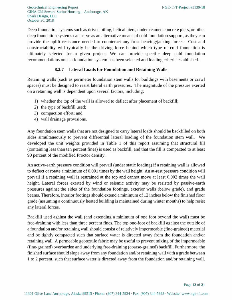
Retaining walls (such as perimeter foundation stem walls for buildings with basements or crawl spaces) must be designed to resist lateral earth pressures. The magnitude of the pressure exerted on a retaining wall is dependent upon several factors, including:
1) whether the top of the wall is allowed to deflect after placement of backfill; 2) the type of backfill used; 3) compaction effort; and 4) wall drainage provisions.
Any foundation stem walls that are not designed to carry lateral loads should be backfilled on both sides simultaneously to prevent differential lateral loading of the foundation stem wall. We developed the unit weights provided in Table 1 of this report assuming that structural fill (containing less than ten percent fines) is used as backfill, and that the fill is compacted to at least 90 percent of the modified Proctor density.
An active-earth pressure condition will prevail (under static loading) if a retaining wall is allowed to deflect or rotate a minimum of 0.001 times by the wall height. An at-rest pressure condition will prevail if a retaining wall is restrained at the top and cannot move at least 0.002 times the wall height. Lateral forces exerted by wind or seismic activity may be resisted by passive-earth pressures against the sides of the foundation footings, exterior walls (below grade), and grade beams. Therefore, interior footings should extend a minimum of 12 inches below the finished floor grade (assuming a continuously heated building is maintained during winter months) to help resist any lateral forces.
Backfill used against the wall (and extending a minimum of one foot beyond the wall) must be free-draining with less than three percent fines. The top one-foot of backfill against the outside of a foundation and/or retaining wall should consist of relatively impermeable (fine-grained) material and be tightly compacted such that surface water is directed away from the foundation and/or retaining wall. A permeable geotextile fabric may be useful to prevent mixing of the impermeable (fine-grained) overburden and underlying free-draining (coarse-grained) backfill. Furthermore, the finished surface should slope away from any foundation and/or retaining wall with a grade between 1 to 2 percent, such that surface water is directed away from the foundation and/or retaining wall.

Geotechnical Engineering Report NGE-TFT Project #5139-18 CIHA Old Seward Senior Housing – Anchorage, AK Spark Design, LLC October 30, 2018
Page 13 of 21
11301 Olive Lane Anchorage, Alaska 99515 · Phone: (907) 344-5934 · Fax: (907) 344-5993 · Website: www.nge-tft.com
Seismic loading on foundation and/or retaining walls generally increases the lateral pressures on the wall and decreases the passive resistance. For foundation systems where the building foundation is continuous, the differential lateral movement between the soil and foundation is very small, and as such, essentially no excess lateral loading on the foundation wall is experienced. Foundation walls with a differential in backfill heights of over six feet (basements, crawl spaces, etc.) will experience seismic lateral loading from the inertial effects of seismic waves passing through the foundation.
The lateral soil pressures can be represented by equivalent fluid pressures. The pressure distribution is a function of wall restraint, seismic loading, and drainage conditions. In Figure 7 of this report we provide distribution diagrams for various loading conditions. In Table 1 of this report we provide the unit weights to be used with the pressure distribution diagrams included in Figure 7.
Table 1: Equivalent Fluid Specific Weight for Lateral Loading Design
LOADING CONDITION
DRAINED EQUIVALENT FLUID SPECIFIC WEIGHT
UN-DRAINED EQUIVALENT FLUID SPECIFIC WEIGHT
SPECIFIC WEIGHT (pcf) SYMBOL SPECIFIC WEIGHT (pcf) SYMBOL
ACTIVE 40 t1 32 t2
AT-REST 75 t3 34 t4
PASSIVE 420 t5 280 t6
SEISMIC 16 (UNRESTRAINED) t7 9 (RESTRAINED) t8
Lateral forces may also be resisted by friction between the concrete foundations and the underlying soil. The frictional resistance may be calculated using a coefficient of friction of 0.4 between the concrete and soil.
8.3 Underground Utilities
In general, the soils in which deep utility trenches (6 to 10 feet bgs) are to be constructed are composed of fill material and/or undisturbed, native glacial till deposits. Any gravity-fed utility trenches extending into the undisturbed, native glacial till deposits should be a minimum of three feet wide at the bottom with the utility piping located in the center of the trenches. Structural fill should be used to bring the gravity-fed utilities to the proper installation grade. Utilities that are not sensitive to settlement may be placed in the existing fill material.
Underground utilities which are susceptible to damage from freezing need to be frost-protected by sufficient amounts of backfill, insulation, and/or active freeze protection systems (e.g., heat tape, thaw wire, etc.); or some combination of the above. Any utilities which are susceptible to damage from freezing that are planned to be constructed less than eight feet below the planned finished

Geotechnical Engineering Report NGE-TFT Project #5139-18 CIHA Old Seward Senior Housing – Anchorage, AK Spark Design, LLC October 30, 2018
Page 14 of 21
11301 Olive Lane Anchorage, Alaska 99515 · Phone: (907) 344-5934 · Fax: (907) 344-5993 · Website: www.nge-tft.com
grade should contain some level of additional frost-protection (e.g., insulation, active freeze protection systems, or a combination of both).
Any insulation used should conform to the specifications detailed in Section 9.6 of this report and should extend a minimum of two feet (and a maximum of four feet) perpendicular to either side of the proposed utility alignment. The thickness of the insulation used will be a function of the burial depth. In general, one inch of insulation is equal to approximately 12 inches of compacted NFS backfill. Underground utilities which are susceptible to damage from freezing should not be constructed within four feet of the planned finished grade (regardless of insulation measures or active freeze-protection systems).
8.4 Pavement Sections
Construction of the pavement section for the proposed driveway and parking areas will be guided (in part) by the amount of cut/fill needed to achieve the final street grade. The composition, structure, and thickness of the pavement section will be further controlled by the frost susceptibility of, and overall potential for ice lens development within, the subgrade soils. Based on our laboratory testing efforts, the existing soils on-site range from F2 to F3 on the MOA frost classification scale. Furthermore, the project site is overlain by approximately 2 to 9 feet of non-structural fill material. Therefore, there must be an appropriate structural section constructed above the existing fill materials in order to reduce the likelihood of future damage to the pavement sections as a result of differential settlement, ice lens development, and subsequent thaw-related settlements. A geo-textile fabric will need to be incorporated into the pavement section design in order to help distribute vehicle loads and reduce the potential for differential settlements resulting from traffic loading. We, therefore, recommend a “floating” pavement section constructed above the existing fill for this project.
There are three primary factors that influence the potential for ice lens formation at a given site:
1. soil gradation (i.e., ability to draw up moisture through capillary tension); 2. the presence of sufficient volumes of water (i.e., surface water, pore water, or groundwater)
near the freeze front to foster ice lens development; and 3. the rate and duration of free-front advancement due to air temperature and wind variations.
All three factors need to occur simultaneously in order for ice lenses to develop in the subgrade. We did not observe groundwater during our exploration program or during our subsequent groundwater monitoring efforts at the project site. Furthermore, the coarse gradation of the subgrade soils are not conductive to capillary water transport. As such, it is our opinion that there exists a relatively low potential for ice lens development in the subgrade soils. We detail our recommended pavement section for construction above the existing frost susceptible soils in Table 2 this report.

Geotechnical Engineering Report NGE-TFT Project #5139-18 CIHA Old Seward Senior Housing – Anchorage, AK Spark Design, LLC October 30, 2018
Page 15 of 21
11301 Olive Lane Anchorage, Alaska 99515 · Phone: (907) 344-5934 · Fax: (907) 344-5993 · Website: www.nge-tft.com
Table 2: Recommended Uninsulated Pavement Section
SECTION THICKNESS
MATERIAL
2 INCHES MIN. ASPHALT CONCRETE (AC) PAVEMENT
2 INCHES MAX. NFS LEVELING COURSE (A.K.A. “D-1” OR RAP)
12 INCHES TYPE II-A
22 INCHES TYPE II or II-A
N/A GEOTEXTILE FABRIC (REQUIRED)
N/A EXISTING SUBGRADE (FILL OR NATIVE GLACIAL TILL)
Confirmation frost classification testing of the subgrade soils should be conducted after the completion of all overburden removal and any utility installation activities. The results of the confirmation frost classification testing can be used to ensure that the proper pavement section is used for the soil conditions exposed.
A permeable geotextile fabric is required for this project. Any geotextile fabric used should meet the specifications in the 2015 Municipality of Anchorage Standard Specifications (MASS), Section 20.25. For the project site, we recommend a Type B, Class 1 (i.e., reinforcement) geotextile fabric. The geotextile fabric may be either: 1) woven, or 2) non-woven with perforations. We have provided the various strengths for both a woven and non-woven Type B, Class 1 geotextile fabric in Table 3 of this report.
Table 3: Type B, Class 1 Geotextile Fabric Strengths
FABRIC PROPERTY ASTM STANDARD USED
TO DETERMINE STRENGTH WOVEN FABRIC
STRENGTH NON-WOVEN
FABRIC STRENGTH
GRAB STRENGTH D4632 315 200
SEWN SEAM STRENGTH D4632 285 182
TEAR STRENGTH D4533 115 80
PUNCTURE STRENGTH D6241 620 435 Note: Units in lbs per foot.
The leveling course, Type II, and Type II-A materials used should conform to the specifications we provide in Figure 8 of this report. Any leveling course used should be NFS in order to maintain a low potential for ice lens development within the leveling course. It is our experience that the “D-1” leveling course material currently available in Anchorage area may not be NFS following compaction, because the compaction with a vibratory compactor further increases the frost susceptibility of the leveling course by increasing the percentage of fine-grained material (due to degradation of the soil particles from the impact of the compaction equipment). As such, we recommend the use of two inches of recycled asphalt pavement (RAP) for the leveling course, as

Geotechnical Engineering Report NGE-TFT Project #5139-18 CIHA Old Seward Senior Housing – Anchorage, AK Spark Design, LLC October 30, 2018
Page 16 of 21
11301 Olive Lane Anchorage, Alaska 99515 · Phone: (907) 344-5934 · Fax: (907) 344-5993 · Website: www.nge-tft.com
RAP has a low frost susceptibility. Otherwise, the leveling course thickness should be kept to two inches or less to reduce the potential for ice lens formation in the leveling course. Type II-A materials can be used as a substitute for Type II materials, as Type II materials are becoming difficult to procure in the Anchorage area. However, no Type II materials should be placed within 12 inches of any pavement surfaces to help reduce the risk of pavement dimpling (from oversized particles contained within the Type II material). All of these materials should be placed in thin lifts and each lift should be compacted to a minimum of 95 percent of the modified Proctor density.
8.5 Surface Drainage
After the property is brought to grade it should be relatively flat, such that storm water will tend to accumulate and flow off the site slowly. Water accumulation will have a detrimental effect on foundations, retaining structures, and pavement sections. Provisions should be included in the design to collect runoff and divert it away from any foundations, retaining structures, and pavement sections. The ground surface surrounding the proposed developments should be graded such that surface runoff is channeled away from foundations, retaining walls, and pavement sections. The soils on the surface should be tightly compacted to help reduce surface runoff infiltration. Roof, parking lot, and driveway drainage should be directed away from foundations. If storm sewer is available, tight-line connections from roof drain collectors should be made.
9.0 CONSTRUCTION RECOMMENDATIONS We have presented our construction recommendations in the general order that the project site will most likely be developed. Our construction recommendations are intended to aid the construction contractor(s) during the construction process.
9.1 Earthwork
Any and all fill material used should be placed at 95 percent of the modified Proctor density as determined by ASTM D-1557, unless specifically stated otherwise in other sections of this report. The thickness of individual lifts will be determined based on the equipment used, the soil type, and existing soil moisture content. Typically, fill material will need to be placed in lifts of less than one-foot in thickness. All earthworks should be completed with quality control inspection.
In our professional experience, structural fill should have less than approximately 15 percent passing the #200 sieve for ease of placement. Soils with higher silt contents can be used within the foundation footprint. However, the effort required to achieve proper compaction of silt-rich soils may be more costly than purchasing better grade materials. The time of year, existing moisture content, rainfall, air temperature, and fill temperature can all have an impact on the effort required to adequately compact silt-rich material.
Any excavated fill or native glacial till deposits soils (which are free of organic material and have relatively low silt contents) which are stockpiled on-site (for later use as structural backfill) should be protected from additional moisture inputs (precipitation, etc.) through the use of plastic tarps,

Geotechnical Engineering Report NGE-TFT Project #5139-18 CIHA Old Seward Senior Housing – Anchorage, AK Spark Design, LLC October 30, 2018
Page 17 of 21
11301 Olive Lane Anchorage, Alaska 99515 · Phone: (907) 344-5934 · Fax: (907) 344-5993 · Website: www.nge-tft.com
etc. Additional moisture inputs can have detrimental effects on the effort needed to achieve proper compaction rates.
9.2 Heated Shallow Foundations
Care should be taken during foundation excavation activities to limit the disturbance of the bottom of any foundation excavations. The bottom of any foundation excavation should be moisture conditioned and proof-rolled as necessary to return the exposed soils to their original in-situ density.
In general, the soils in which the proposed foundation pads are to be constructed consist primarily undisturbed, native glacial till deposits or properly placed structural fill. As such, any surface water (e.g., from precipitation, snowmelt, etc.) that enters into foundation excavations may tend to dissipate relatively fast. Excess water will have a negative impact on any backfill and compaction efforts. Therefore, if surface water does accumulate in any open foundation excavations it can be controlled by excavating a shallow drainage trench around the perimeter of the excavation. The drainage trench will collect surface water and direct it to a sump area, which should be located outside of the foundation footprint. The excess water can then be pumped from the sump area and be discharged at an appropriate location away from the excavation and any other existing foundations.
It is imperative that shallow building foundations for heated structures remain in a thawed state for the entire construction period; even when dealing with soils that have little to no frost susceptibility. Foundation soils that are allowed to freeze during the initial construction (before the building is enclosed and heated) may be compromised by the development of ice lenses. Upon thawing, which may take several weeks or months, potential differential settlements could distort the structure resulting in damaged foundations, cracked sheetrock, skewed door frames, and broken windows. If construction extends into the winter months, temporary enclosures should be constructed which completely enclose warm foundations and heat should be applied to the enclosure to prevent freezing of the soils located beneath any warm foundation and/or floor slab.
9.3 Cold (Unheated) Shallow Foundations
The frost susceptibility of the existing native glacial till deposits (as we describe in Section 7.5 of this report) range from F2 to F3. Therefore, the existing native glacial till deposits are unsuitable to support any cold (unheated) shallow foundations without freeze protection, as they may experience ice lens development and/or thaw-weakening, which could result in damages to the proposed foundations. As we mention in Section 8.2.6 of this report, the minimum cold foundation burial depth (D3) can be reduced, if the foundation is placed on a structural pad constructed of NFS fill. The NFS structural pad thickness may be reduced by using insulation at a rate of one inch of insulation to one foot of NFS material.

Geotechnical Engineering Report NGE-TFT Project #5139-18 CIHA Old Seward Senior Housing – Anchorage, AK Spark Design, LLC October 30, 2018
Page 18 of 21
11301 Olive Lane Anchorage, Alaska 99515 · Phone: (907) 344-5934 · Fax: (907) 344-5993 · Website: www.nge-tft.com
9.4 Underground Utilities
We expect that utility trench wall stability in the existing fill and/or undisturbed, native glacial till deposits be moderate. The utility trench wall stability may decrease where utility trenches extend below the groundwater table. However, we do not expect groundwater during utility trench excavations. The contractor should be responsible for trench safety and regulation compliance. If groundwater is encountered during utility trench excavation, then dewatering efforts may be required to facilitate proper utility installation and trench backfill.
All piping should be bedded per the manufacturer’s recommendations, with the bedding material compacted to provide pipe support. Above the bedding materials, the backfill should be similar to, and compacted to the approximate density of, the surrounding soils.
9.5 Pavement
All of the earthwork within any areas to be paved should be completed as early in the construction schedule as possible, and the pavement placed as late in the construction schedule as possible. This will give the subgrade soils time to settle, compress, and stabilize prior to placement of the pavement. Any structural fill used should be placed in thin lifts (less than one foot in thickness) and each lift should be compacted to a minimum of 95 percent of the modified Proctor density. Prior to paving, any surface fill material should be re-leveled and re-compacted. All backfill and paving materials should be inspected and tested for material specification compliance and compaction.
Underground utility piping should be installed prior to construction of any pavement sections such that trenching is done through the subgrade soils only. This will help ensure that a uniform pavement section is maintained, which will reduce the potential for differential settlements along underground utility trench alignments.
The minimum thickness for any asphalt concrete (AC) pavement surfaces is two inches. The minimum thickness of any Portland cement concrete (PCC) pavement surfaces will be a function of the reinforcement required. All applicable ACI and IBC standards should be followed.
9.6 Insulation
The satisfactory performance of any subsurface insulation is in part controlled by the details of construction including: 1) the care taken to ensure that the board stock lies flat on a smooth, level surface; and 2) the adjoining ends of the insulation are closely butted together. Any vertical joints should be staggered where more than one layer of insulation is used.
9.7 Winter Construction
Proper placement and compaction of structural fill is not possible when fill material is frozen, and as such, frozen fill material should never be used for structural support unless it has been

Geotechnical Engineering Report NGE-TFT Project #5139-18 CIHA Old Seward Senior Housing – Anchorage, AK Spark Design, LLC October 30, 2018
Page 19 of 21
11301 Olive Lane Anchorage, Alaska 99515 · Phone: (907) 344-5934 · Fax: (907) 344-5993 · Website: www.nge-tft.com
subsequently thawed and compacted to 95 percent of the modified Proctor density (throughout its vertical extent). Furthermore, subgrade soils (fill or native) need to be completely thawed prior to the placement and compaction of additional lifts of thawed fill material. In our professional
experience, ambient soil temperatures need to be above 37 F in order to achieve efficient compaction. It is extremely difficult to achieve compaction levels equal to 95 percent of the
modified Proctor density in fill material that is between 32 F to 37 F.
10.0 THE OBSERVATIONAL METHOD A comprehensive geoprofessional service (e.g., geotechnical, geological, civil, and/or environmental engineering, etc.) should consist of an interdependent, two-part process comprised of:
Part I - pre-construction site assessment, engineering, and design; and
Part II - continuous construction oversight and design support.
This process, commonly referred to in the geoprofessional industry as “The Observational Method”, was developed to reduce the costs required to complete a construction project, while simultaneously reducing the overall risk associated with the design and construction of the project.
In geotechnical engineering, Part I of the Observational Method (OM) begins with a geotechnical assessment of the site, which typically consists of some combination of literature research, site reconnaissance, subsurface exploration, laboratory testing, and geotechnical engineering. These efforts are usually documented in a formal report (e.g., such as this report) that summarizes the findings of the geotechnical assessment, and presents provisional geotechnical engineering recommendations for design and construction. Geotechnical assessment reports (and the findings and recommendations contained within) are considered provisional due to the fact that their contents are typically based primarily on limited subsurface information for a site. Most conventional geotechnical exploration programs only physically characterize a very small percentage of a given site, as it is typically cost prohibitive to conduct extensive (i.e. high density/frequency) exploration programs. As an alternative, geoprofessionals use the subsurface information available for a site to extrapolate subsurface conditions between exploration locations and develop appropriate provisional recommendations based on the inferred site conditions. As a result, the geoprofessional of record cannot be certain that the provisional recommendations will be wholly applicable to the site, as subsurface conditions other than those identified during the geotechnical assessment may exist at the site which could present obstacles and/or increased risk to the proposed design and construction.
Part II of the OM is employed by geoprofessionals to help reduce the risk associated with unidentified and/or unexpected subsurface conditions. Geoprofessionals accomplish Part II of the OM by providing construction oversight (e.g., construction observation, inspection, and testing). Part II of the OM is a valuable service, as the geoprofessional of record is available if unexpected

Geotechnical Engineering Report NGE-TFT Project #5139-18 CIHA Old Seward Senior Housing – Anchorage, AK Spark Design, LLC October 30, 2018
Page 20 of 21
11301 Olive Lane Anchorage, Alaska 99515 · Phone: (907) 344-5934 · Fax: (907) 344-5993 · Website: www.nge-tft.com
conditions are encountered during the construction process (e.g., during excavation, fill placement, etc.) to make timely assessments of the unexpected conditions and modify their design and construction recommendations accordingly; thus reducing considerable cost resulting from potential construction delays and reducing the risk of future problems resulting from inappropriate design and construction practices.
Oftentimes, a client may be persuaded to use an alternative geoprofessional firm to conduct Part II of the OM for a given project; as some geoprofessional firms offer the same services at discounted prices in order to help them obtain the overall construction materials engineering and testing (CoMET) commission. The geoprofessional industry as a whole recommends against this practice. An alternative geoprofessional firm cannot provide the same level of service as the geoprofessional of record. The geoprofessional of record has (amongst other things) a unique familiarity with the project including; an intimate understanding of the subsurface conditions, the proposed design, and the client’s unique concerns and needs, as well as other factors that could impact the successful completion of a construction project. An alternative geoprofessional firm is not aware of the inferences made and the judgment applied by the geoprofessional of record in developing the provisional recommendations, and may overlook opportunities to provide extra value during Part II of the geoprofessional service.
Clients that prevent the geoprofessional of record from performing a complete service can be held solely liable for any complications stemming from engineering omissions as a result of unidentified conditions. The geoprofessional of record may not be liable for any resulting complications that occur, as the geoprofessional of record was not able to complete their services. Furthermore, the replacement geoprofessional firm may also be found to have no liability for the same reasons.
We are available at any time to discuss the OM in more detail, or to provide you with an estimate for any additional construction observation and testing services required.
11.0 CLOSURE We (Northern Geotechnical Engineering, Inc. d.b.a. Terra Firma Testing) prepared this report exclusively for the use Spark Design, LLC and their client/consultants/contractors/etc. for use in the design and construction of the proposed improvements. We should be notified if significant changes are to occur in the nature, design, or location of the proposed improvements in order that we may review our conclusions and recommendations that we present in this report and, if necessary, modify them to satisfy the proposed changes.
This report should always be read and/or distributed in its entirety (including all figures, exploration logs, appendices, etc.) so that all of the pertinent information contained within is effectively disseminated. Otherwise, an incomplete or misinterpreted understanding of the site conditions and/or our engineering recommendations may occur. Our recommended best practice is to make this report accessible, in its entirety, to any design professional and/or contractor

Geotechnical Engineering Report NGE-TFT Project #5139-18 CIHA Old Seward Senior Housing – Anchorage, AK Spark Design, LLC October 30, 2018
Page 21 of 21
11301 Olive Lane Anchorage, Alaska 99515 · Phone: (907) 344-5934 · Fax: (907) 344-5993 · Website: www.nge-tft.com
working on the project. Any part of this report (e.g., exploration logs, calculations, material values, etc.) which is presented in the design/construction plans and/or specifications for the project should have an adequate reference which clearly identifies where the report can be obtained for further review.
Due to the natural variability of earth materials, variations in the subsurface conditions across the project site may exist other than those we identified during the course of our geotechnical assessment. Therefore, a qualified geotechnical engineer, geologist, and/or special inspector be on-site during construction activities to provide corrective recommendations for any unexpected conditions revealed during construction (see our discussion of the Observational Method in Section 10.0 of this report for more detail). Furthermore, the construction budget should allow for any unanticipated conditions that may be encountered during construction activities.
We conducted this evaluation following the standard of care expected of professionals undertaking similar work in the State of Alaska under similar conditions. No warranty, expressed or implied, is made.

NGE-TFT Project #5139-18
REPORT FIGURES

FIGURE NUMBER:
PROJECT ID:
PROJECT LOCATION:
PROJECT NAME:
FIGURE TITLE:
ALASKA ANCHORAGE
PROJECT SITE LOCATION MAP
CHIA OLD SEWARD SENIOR HOUSING
ANCHORAGE, AK
5139-18
1
= PROJECT SITE

FIGURE NUMBER:
PROJECT ID:
PROJECT LOCATION:
PROJECT NAME:
FIGURE TITLE:
CURRENT SURFACE TOPOGRAPHY AND EXPLORATION LOCATIONS
CHIA OLD SEWARD SENIOR HOUSING
ANCHORAGE, ALASKA
5139-18
2
B8
B3
B5
B7
B6
B1
B2
B4
B9
= APPROX. BOREHOLE LOCATION
BASE IMAGE PRODUCED BY GASTALDI LAND SURVEY, LLC (OCTOBER 12, 2018)

FIGURE NUMBER:
PROJECT ID:
PROJECT LOCATION:
PROJECT NAME:
FIGURE TITLE:
PROPOSED SITE LAYOUT
CHIA OLD SEWARD SENIOR HOUSING
ANCHORAGE, ALASKA
5139-18
3
35% DRAWINGS PROVIDED BY SPARK DESIGN, LLC

FIGURE NUMBER:
PROJECT ID:
PROJECT LOCATION:
PROJECT NAME:
FIGURE TITLE:
BLOW COUNT CORRECTIONS
CHIA OLD SEWARD SENIOR HOUSING
ANCHORAGE, AK
5139-18
4
Notes:
• Overburden correction factor is used only for cohesionless soils
• CN is the ratio of the measured blow count to what the blow count would be at an overburden pressure of 1 ton/ft2
• σ’vo is the effective overburden pressure at the point of measurement (ton/ft2)
Liao and Whitman, 1986. Skempton, 1986.
vo
NC
=1

FIGURE NUMBER:
PROJECT ID:
PROJECT LOCATION:
PROJECT NAME:
FIGURE TITLE:
FOOTING UPLIFT CAPACITY DIAGRAM
CHIA OLD SEWARD SENIOR HOUSING
ANCHORAGE, AK
5139-18
5
UPLIFT CAPACITY = 0.8 × (EFFECTIVE SOIL WEIGHT + WEIGHT OF FOUNDATION)
FINISH GRADE
FOUNDATION WEIGHT
EFFECTIVE
SOIL MASS
45° 45°
FOUNDATION WIDTH (X)
FOUNDATION FOOTING
EXTENSION (MIN.: 0.125X)
DRAWING NOT TO SCALE
= FOOTING / STEM WALL

PROJECT ID:
FIGURE TITLE:
PROJECT NAME:
PROJECT LOCATION: FIGURE NUMBER:
CRAWL SPACE
INTERIOR FINISHED GRADE
SHALLOW FOUNDATION FOOTING LOCATED ENTIRELY WITHIN AN ENCLOSED, CONTINUOUSLY HEATED SPACE*
INTERIOR SPREAD FOOTING /
GRADE BEAM
CO
LU
MN
/
ST
EM
WA
LL
FLOOR
SLAB
SHALLOW FOUNDATION FOOTING LOCATED ALONG THE PERIMETER OF AN ENCLOSED, CONTINUOUS HEATED
SPACE*
D1 D1
EXTERIOR FINISHED GRADE
D2 D2
CRAWL SPACE
FLOOR
SLAB
FOOTING FOOTING
ST
EM
WA
LL
ST
EM
WA
LL
ENCLOSED, HEATED
SPACE ENCLOSED, HEATED
SPACE
SHALLOW FOUNDATION FOOTING EXPOSED TO FREEZING TEMPERATURES
FOOTING
ST
EM
WA
LL
EXTERIOR FINISHED GRADE
INTERIOR FINISH GRADE
DRAWING NOT TO SCALE
D3
UNHEATED SPACE
ENCLOSED, HEATED
SPACE
ENCLOSED, HEATED SPACE
FOOTING
ST
EM
WA
LL
INTERIOR FINISH GRADE
D3
INTERIOR SPREAD FOOTING /
GRADE BEAM
*HEATED FOUNDATION TEMPERATURE MUST BE CONTINUOUSLY MAINTAINED AT/ABOVE 400F
UNINSULATED SHALLOW FOUNDATION CONFIGURATIONS
CHIA OLD SEWARD SENIOR HOUSING
ANCHORAGE, AK
5139-18
6

DRAWING NOT TO SCALE
FIGURE NUMBER:
PROJECT ID:
PROJECT LOCATION:
PROJECT NAME:
FIGURE TITLE:
NOTE: INSULATION FOR HEATING EFFICIENCY PURPOSES ONLY. IF INSULATION IS PLACED UNDER FLOOR/SLAB USE CONFIGURATION C.
TE CAN BE ANY THICKNESS
NOTE: DO NOT INSULATE BOTTOM OF FOOTING. TS CAN BE ANY
THICKNESS. EXTERIOR INSULATION NOT REQUIRED IF FLOOR IS
NOT INSULATED (SEE CONFIGURATION A)
TH
ICK
EN
ED
ED
GE
SL
AB
HEATED FOUNDATIONS (CONTINUOUSLY HEATED INTERIOR SPACE)* COLD (UNHEATED) FOUNDATIONS
MIN 42”
CONFIGURATION C
SOILS PREPARED AS DESCRIBED IN TEXT
TE=TS+4”
MIN 16”
TE
12TE
SOILS PREPARED AS DESCRIBED IN TEXT
CONFIGURATION B
TE
12TE
SOILS PREPARED AS DESCRIBED IN TEXT
CONFIGURATION D
TE=TS+4”
NOTE: DO NOT INSULATE BOTTOM OF THICKENED EDGE FOOTING.
TS CAN BE ANY THICKNESS.
TS
FINISHED GRADE FINISHED GRADE
FINISHED GRADE
TE=TS+4”
TE=TS+4”
NOTE: IF INSULATION IS PLACED UNDER SLAB USE
CONFIGURATION D. TE MINIMUM = 2”.
THICKENED EDGE
SLAB
TF = INSULATION THICKNESS UNDER ENTIRE FOUNDATION (INCHES)
TS= INSULATION THICKNESS UNDER FLOOR/SLAB ONLY (INCHES)
TE = INSULATION ALONG EXTERIOR OF FOUNDATION (INCHES)
*HEATED FOUNDATION TEMPERATURE MUST BE CONTINUOUSLY MAINTAINED AT/ABOVE 40F
EXISTING FROST SUSCEPTIBLE SUBGRADE
FINISHED GRADE
12TF
TF
MIN. 18” NFS
NFS FILL
CONFIGURATION F
NOTE: INSULATION OPTIONAL TO REDUCE DEPTH OF NFS FILL AT A RATE OF 1” INSULATION TO 12” NFS FILL. TF MIN. = 1”
EXISTING FROST SUSCEPTIBLE SUBGRADE
PER TEXT (D2)
CONFIGURATION E
12TF
MIN. 18” NFS
TF
NOTE: INSULATION OPTIONAL TO REDUCE DEPTH OF NFS FILL AT A RATE OF 1” INSULATION TO 12” NFS FILL. TF MIN. = 1”
FINISHED GRADE
= RIGID BOARD INSULATION
**FLOOR SYSTEM CAN BE STRUCTURAL (W/ CRAWLSPACE) OR SLAB-ON-GRADE
THICKENED EDGE
SLAB
THICKENED EDGE
SLAB
PER TEXT (D3)
BEDDING/NFS FILL
ST
RIP
FO
OT
ING
/ST
EM
WA
LL
MIN 42”
CONFIGURATION A
SOILS PREPARED AS DESCRIBED IN TEXT
FINISHED GRADE FLOOR/SLAB**
TE
ST
EM
WA
LL
FOOTING
INTERIOR GRADE (FOR STRUCTURES
W/ SUB-FLOOR CRAWL SPACES
CRAWL SPACE/FILL
FLOOR/SLAB**
ST
EM
WA
LL
INTERIOR GRADE (FOR STRUCTURES
W/ SUB-FLOOR CRAWL SPACES
CRAWL SPACE/FILL
FOOTING
TS
FLOOR/SLAB**
ST
EM
WA
LL
FOOTING
INTERIOR GRADE (FOR STRUCTURES
W/ SUB-FLOOR CRAWL SPACES
CRAWL SPACE/NFS FILL
PER TEXT (D3)
FOR STRUCTURES W/
CRAWLSPACES
PER TEXT (D3)
BEDDING/NFS FILL
MIN 16” MIN 16”
INSULATED SHALLOW FOUNDATION CONFIGURATIONS
CHIA OLD SEWARD SENIOR HOUSING
ANCHORAGE, AK
5139-18
7

FIGURE NUMBER:
PROJECT ID:
PROJECT LOCATION:
PROJECT NAME:
FIGURE TITLE:
H
t1H
DRAINAGE PIPE
ACTIVE PRESSURE CONDITION AT-REST PRESSURE CONDITION
PASSIVE PRESSURE CONDITION SEISMIC
H
WITH DRAINAGE WITHOUT DRAINAGE
t1(H-H1)
t2H1 + t1(H-H1)
+
H1
MAX
ANTICIPATED
62.4H1
H
t5H
DRAINAGE PIPE
H
WITH DRAINAGE WITHOUT DRAINAGE
t5(H-H1)
t6H1 + t5(H-H1)
-
H1
62.4H1
H
t3H
DRAINAGE PIPE
H
WITH DRAINAGE WITHOUT DRAINAGE
t3(H-H1)
t4H1 + t3(H-H1)
+
H1
MAX
ANTICIPATED
62.4H1
H
t7H
H t8H
RESTRAINED UNRESTRAINED
NOTE: SEISMIC LOADS ARE VALID FOR WALLS RETAINING LESS THAN 8 FEET VERTICAL
OF EARTH. THE SEISMIC LOAD IS ADDED TO ACTIVE CONDITIONS AND IS SUBTRACTED
FROM PASSIVE CONDITIONS.
LATERAL RETAINING WALL PRESSURE SCHEMATICS
CHIA OLD SEWARD SENIOR HOUSING
ANCHORAGE, AK
5139-18
8
NOTE: WALLS CAN BE EITHER FREE OR RESTRAINED AT THE TOP FOR THE PASSIVE PRES-
SURE CONDITION. EQUATIONS ARE ONLY VALID FOR UNITS OF t1-8 (PCF) AND H-H1(FT).
MAX
ANTICIPATED

PROJECT ID:
FIGURE TITLE:
PROJECT NAME:
PROJECT LOCATION: FIGURE NUMBER:
MOA MATERIAL SPECIFICATIONS
CHIA OLD SEWARD SENIOR HOUSING
ANCHORAGE, AK
5139-18
9
LEVELING COURSE
SIEVE SIZE % BY MASS PASSING
1” 100
3/4” 70-100
3/8” 50-80
#4 35-65
#8 20-50
#50 8-28
#200 2-6
0.02 0-3
TYPE II
SIEVE SIZE % BY MASS PASSING
8” 100
3” 70-100
1-1/2” 55-100
3/4” 45-85
#4 20-60
#10 12-50
#40 4-30
#200 *2-6
0.02 0-3
*IN ADDITION TO THE GRADING LIMITS LISTED ABOVE, THE FRACTION OF MATERIAL PASSING THE #200 SIEVE SHALL NOT BE
GREATER THAN FIFTEEN PERCENT (15 %) OF THAT FRACTION PASSING THE #4 SIEVE.
TYPE II - A
SIEVE SIZE % BY MASS PASSING
3” 100
3/4” 50-100
#4 25-60
#10 15-50
#40 4-30
#200 *2-6
0.02 0-3
*IN ADDITION TO THE GRADING LIMITS LISTED ABOVE, THE FRACTION OF MATERIAL PASSING THE #200 SIEVE SHALL NOT BE
GREATER THAN TWENTY PERCENT (20 %) OF THAT FRACTION PASSING THE #4 SIEVE.

NGE-TFT Project #5139-18
APPENDIX A
GRAPHICAL BOREHOLE LOGS AND SPLIT-SPOON SAMPLE PHOTOGRAPHS

25
23
12
36
37
55
71
48
18
14
12
19
15
18
18
18
478
768
236
121516
101819
263029
152550
42037
S1
S2
S3
S4
S5
S6
S7
S8
Always refer to our complete geotechnical report for this project for a more detailed explanation of the subsurfaceconditions at the project site and how they may affect any existing and/or prospective project site development.
NGE-TFT PROJECT NAME: Lot 4, Recycled Properties Subd. NGE-TFT PROJECT NUMBER: 4718-17
PROJECT LOCATION: Anchorage, AK
Northern Geotechnicaal Engineering andTerra Firma Testing11301 Olive LaneAnchorage, AK 99515Telephone: 907-344-5934
PAGE 1 OF 1
DE
PT
H(f
t)
0
5
10
15
20
25
GR
AP
HIC
LOG
FR
OZ
EN
SO
ILS
EXPLORATION METHOD: Hollow Stem Auger w/ Center Drill Rods
DATE COMPLETED: 6/28/2017
SAMPLING METHOD: Modified Split-spoon w/ 340lb autohammer
EXPLORATION CONTRACTOR: Discovery Drilling, Inc.
LOGGED BY: S. McCoy
EXPLORATION COMPLETION: Backfilled w/ cuttings
EXPLORATION EQUIPMENT: CME 55
WEATHER CONDITIONS:
DATE STARTED: 6/28/2017
EXPLORATION LOCATION: See Figure 2 in the report
EXPLORATION B1
GROUND ELEVATION: Not Known
GROUNDWATER (ATD): GROUNDWATER ():
SA
MP
LE T
YP
E
(N1)
60
RE
CO
VE
RY
(in
)
FIE
LD B
LOW
S
FIE
LD S
AM
PLE
ID
LA
B R
ES
ULT
S
SILTY GRAVEL TO GRAVEL WITH SILT AND SAND (GM), brown, damp, gravel up to 0.5'' indiameter, trace organics near surface
SILTY SAND WITH GRAVEL (SM), trace organics, brown, damp, gravel up to 2'' in diameter
SAND WITH GRAVEL (SP), medium dense, brown to reddish brown, damp to moist, gravel up to1'' in diameter, some interbedded sand layers SILTY SAND WITH GRAVEL (SM), very dense to hard, brown, damp, gravel up to 1'' in diameter
Bottom of borehole at 26.5 ft bgs.
MATERIAL DESCRIPTION

PHOTO APPENDIX
Exploration B1 Sample S2Sample Interval 2.5 - 4 ft bgs
Exploration B1 Sample S1Sample Interval 0 - 1.5 ft bgs
CLIENT Cook Inlet housing Authority
PROJECT NUMBER 4718-17
PROJECT NAME Lot 4, Recycled Properties Subd.
PROJECT LOCATION Anchorage, AK
Northern Geotechnical Engineering Inc. d.b.a. Terra Firma Testing11301 Olive LaneAnchorage, AK 99515Telephone: 907-344-5934Fax: 907-344-5993

PHOTO APPENDIX
Exploration B1 Sample S4Sample Interval 7.5 - 9 ft bgs
Exploration B1 Sample S3Sample Interval 5 - 6.5 ft bgs
CLIENT Cook Inlet housing Authority
PROJECT NUMBER 4718-17
PROJECT NAME Lot 4, Recycled Properties Subd.
PROJECT LOCATION Anchorage, AK
Northern Geotechnical Engineering Inc. d.b.a. Terra Firma Testing11301 Olive LaneAnchorage, AK 99515Telephone: 907-344-5934Fax: 907-344-5993

PHOTO APPENDIX
Exploration B1 Sample S6Sample Interval 15 - 16.5 ft bgs
Exploration B1 Sample S5Sample Interval 10 - 11.5 ft bgs
CLIENT Cook Inlet housing Authority
PROJECT NUMBER 4718-17
PROJECT NAME Lot 4, Recycled Properties Subd.
PROJECT LOCATION Anchorage, AK
Northern Geotechnical Engineering Inc. d.b.a. Terra Firma Testing11301 Olive LaneAnchorage, AK 99515Telephone: 907-344-5934Fax: 907-344-5993

PHOTO APPENDIX
Exploration B1 Sample S8Sample Interval 25 - 26.5 ft bgs
Exploration B1 Sample S7Sample Interval 20 - 21.5 ft bgs
CLIENT Cook Inlet housing Authority
PROJECT NUMBER 4718-17
PROJECT NAME Lot 4, Recycled Properties Subd.
PROJECT LOCATION Anchorage, AK
Northern Geotechnical Engineering Inc. d.b.a. Terra Firma Testing11301 Olive LaneAnchorage, AK 99515Telephone: 907-344-5934Fax: 907-344-5993
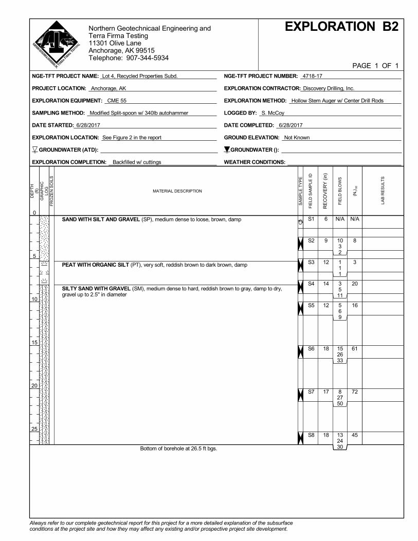
N/A
8
3
20
16
61
72
45
6
9
12
14
12
18
17
18
N/A
1032
111
3511
569
152633
82750
132430
S1
S2
S3
S4
S5
S6
S7
S8
Always refer to our complete geotechnical report for this project for a more detailed explanation of the subsurfaceconditions at the project site and how they may affect any existing and/or prospective project site development.
NGE-TFT PROJECT NAME: Lot 4, Recycled Properties Subd. NGE-TFT PROJECT NUMBER: 4718-17
PROJECT LOCATION: Anchorage, AK
Northern Geotechnicaal Engineering andTerra Firma Testing11301 Olive LaneAnchorage, AK 99515Telephone: 907-344-5934
PAGE 1 OF 1
DE
PT
H(f
t)
0
5
10
15
20
25
GR
AP
HIC
LOG
FR
OZ
EN
SO
ILS
EXPLORATION METHOD: Hollow Stem Auger w/ Center Drill Rods
DATE COMPLETED: 6/28/2017
SAMPLING METHOD: Modified Split-spoon w/ 340lb autohammer
EXPLORATION CONTRACTOR: Discovery Drilling, Inc.
LOGGED BY: S. McCoy
EXPLORATION COMPLETION: Backfilled w/ cuttings
EXPLORATION EQUIPMENT: CME 55
WEATHER CONDITIONS:
DATE STARTED: 6/28/2017
EXPLORATION LOCATION: See Figure 2 in the report
EXPLORATION B2
GROUND ELEVATION: Not Known
GROUNDWATER (ATD): GROUNDWATER ():
SA
MP
LE T
YP
E
(N1)
60
RE
CO
VE
RY
(in
)
FIE
LD B
LOW
S
FIE
LD S
AM
PLE
ID
LA
B R
ES
ULT
S
SAND WITH SILT AND GRAVEL (SP), medium dense to loose, brown, damp
PEAT WITH ORGANIC SILT (PT), very soft, reddish brown to dark brown, damp
SILTY SAND WITH GRAVEL (SM), medium dense to hard, reddish brown to gray, damp to dry,gravel up to 2.5'' in diameter
Bottom of borehole at 26.5 ft bgs.
MATERIAL DESCRIPTION

PHOTO APPENDIX
Exploration B2 Sample S3Sample Interval 5 - 6.5 ft bgs
Exploration B2 Sample S2Sample Interval 2.5 - 4 ft bgs
CLIENT Cook Inlet housing Authority
PROJECT NUMBER 4718-17
PROJECT NAME Lot 4, Recycled Properties Subd.
PROJECT LOCATION Anchorage, AK
Northern Geotechnical Engineering Inc. d.b.a. Terra Firma Testing11301 Olive LaneAnchorage, AK 99515Telephone: 907-344-5934Fax: 907-344-5993

PHOTO APPENDIX
Exploration B2 Sample S5Sample Interval 10 - 11.5 ft bgs
Exploration B2 Sample S4Sample Interval 7.5 - 9 ft bgs
CLIENT Cook Inlet housing Authority
PROJECT NUMBER 4718-17
PROJECT NAME Lot 4, Recycled Properties Subd.
PROJECT LOCATION Anchorage, AK
Northern Geotechnical Engineering Inc. d.b.a. Terra Firma Testing11301 Olive LaneAnchorage, AK 99515Telephone: 907-344-5934Fax: 907-344-5993

PHOTO APPENDIX
Exploration B2 Sample S7Sample Interval 20 - 21.5 ft bgs
Exploration B2 Sample S6Sample Interval 15 - 16.5 ft bgs
CLIENT Cook Inlet housing Authority
PROJECT NUMBER 4718-17
PROJECT NAME Lot 4, Recycled Properties Subd.
PROJECT LOCATION Anchorage, AK
Northern Geotechnical Engineering Inc. d.b.a. Terra Firma Testing11301 Olive LaneAnchorage, AK 99515Telephone: 907-344-5934Fax: 907-344-5993

PHOTO APPENDIX
Exploration B2 Sample S8Sample Interval 25 - 26.5 ft bgs
CLIENT Cook Inlet housing Authority
PROJECT NUMBER 4718-17
PROJECT NAME Lot 4, Recycled Properties Subd.
PROJECT LOCATION Anchorage, AK
Northern Geotechnical Engineering Inc. d.b.a. Terra Firma Testing11301 Olive LaneAnchorage, AK 99515Telephone: 907-344-5934Fax: 907-344-5993

S1
S2AS2B
S3
S4
S5
S7
S8
N/A
N/A
N/A
N/A
N/A
N/A
N/A
N/A
16
13
18
17
18
6
20
18
323
1210334841162729
152134
50/3
71419
133650 1"
S1
S2
S3
S4
S5
S6
S7
S8
P200 = 45.2%OC = 4.6%
46.0% gravel,39.7% sand,
14.3% silt
P200 = 42.6%
Broken rocks insampler from approx.6.75-7 ft bgs.
Lots of broken rocksin sampler.
Cobble blocking endof sampler. Poorrecovery.
Always refer to our complete geotechnical report for this project for a more detailed explanation of the subsurfaceconditions at the project site and how they may affect any existing and/or prospective project site development.
NGE-TFT PROJECT NAME: CIHA Old Seward Senior Housing NGE-TFT PROJECT NUMBER: 5139-18
PROJECT LOCATION: Anchorage, AK
Northern Geotechnicaal Engineering andTerra Firma Testing11301 Olive LaneAnchorage, AK 99515Telephone: 907-344-5934
PAGE 1 OF 1
DE
PT
H(f
t)
0
5
10
15
20
25
30
GR
AP
HIC
LOG
FR
OZ
EN
SO
ILS
EXPLORATION METHOD: Hollow Stem Auger
DATE/TIME COMPLETED: 10/3/2018 @ 12:45:00 PM
SAMPLING METHOD: Modified Split-spoon w/ 340lb autohammer
EXPLORATION CONTRACTOR: Discovery Drilling, Inc.
LOGGED BY: A. Smith
EXPLORATION COMPLETION: See comments below
EXPLORATION EQUIPMENT: CME-85
WEATHER CONDITIONS: Overcast, calm, 50°F
DATE/TIME STARTED: 10/3/2018 @ 10:40:00 AM
EXPLORATION LOCATION: See report Figure 2
EXPLORATION B3
GROUND ELEVATION: Not Known
GROUNDWATER (ATD): None observed GROUNDWATER (10/4/2018): None observed
WE
LLD
IAG
RA
M
SA
MP
LE T
YP
E
LAB
SA
MP
LE ID
(N1)
60
RE
CO
VE
RY
(in
)
SA
MP
LE IN
T. C
OLL
EC
T
FIE
LD B
LOW
S
FIE
LD S
AM
PLE
ID
LA
B R
ES
ULT
S
REMARKS/NOTES
FILL, SILTY SAND WITH GRAVEL (SM), loose, olivebrown, damp, gravel up to 1'' in diameter, trace organics
FILL, SAND WITH SILT AND GRAVEL (SP-SM), traceorganics, loose, olive brown, damp NATIVE, SILTY SAND (SM), loose, orangish brown, damp SAND WITH GRAVEL (SP-SM), medium dense to dense,olive brown, damp, gravel up to 3'' in diameter GLACIAL TILL DEPOSITS, SILTY SAND WITH GRAVEL(SM), dense, olive gray, damp, gravel up to 3'' in diameter
Bottom of borehole at 31.1 ft bgs. Set 1" PVC to BOH. Hand slotted casing from approx.
31.1-16 ft bgs. Backfilled with cuttings from 31.1-3 ft bgs,then hydrated chips from 3-0.5 ft bgs and cuttings from 0.5-0
ft bgs.
MATERIAL DESCRIPTION

Exploration B3 Sample S2Sample Interval 5.5 - 7 ft bgs
Exploration B3 Sample S1Sample Interval 2.5 - 4 ft bgs
PHOTO LOGEXPLORATION B3
CLIENT CIHA
PROJECT NUMBER 5139-18
PROJECT NAME CIHA Old Seward Senior Housing
PROJECT LOCATION Anchorage, AK
Northern Geotechnical Engineering, Inc. d.b.a. Terra Firma Testing11301 Olive LaneAnchorage, AK 99515Telephone: 907-344-5934Fax: 907-344-5993

Exploration B3 Sample S4Sample Interval 10 - 11.5 ft bgs
Exploration B3 Sample S3Sample Interval 7.5 - 9 ft bgs
PHOTO LOGEXPLORATION B3
CLIENT CIHA
PROJECT NUMBER 5139-18
PROJECT NAME CIHA Old Seward Senior Housing
PROJECT LOCATION Anchorage, AK
Northern Geotechnical Engineering, Inc. d.b.a. Terra Firma Testing11301 Olive LaneAnchorage, AK 99515Telephone: 907-344-5934Fax: 907-344-5993

Exploration B3 Sample S6Sample Interval 20 - 21.5 ft bgs
Exploration B3 Sample S5Sample Interval 15 - 16.5 ft bgs
PHOTO LOGEXPLORATION B3
CLIENT CIHA
PROJECT NUMBER 5139-18
PROJECT NAME CIHA Old Seward Senior Housing
PROJECT LOCATION Anchorage, AK
Northern Geotechnical Engineering, Inc. d.b.a. Terra Firma Testing11301 Olive LaneAnchorage, AK 99515Telephone: 907-344-5934Fax: 907-344-5993

Exploration B3 Sample S8Sample Interval 30 - 31.1 ft bgs
Exploration B3 Sample S7Sample Interval 25 - 26.5 ft bgs
PHOTO LOGEXPLORATION B3
CLIENT CIHA
PROJECT NUMBER 5139-18
PROJECT NAME CIHA Old Seward Senior Housing
PROJECT LOCATION Anchorage, AK
Northern Geotechnical Engineering, Inc. d.b.a. Terra Firma Testing11301 Olive LaneAnchorage, AK 99515Telephone: 907-344-5934Fax: 907-344-5993

S0
S1
S2
S4
S5
N/A
N/A
N/A
N/A
N/A
N/A
10
14
0
15
18
342
349
478
91312
142630
S0
S1
S2
S3
S4
S5
P200 = 25.9%
61.0% gravel,30.9% sand,
8.1% silt
37.4% gravel,39.3% sand,
23.3% siltP0.02 = 11.2%
FC = F2
Some cobbles atapprox. 10" bgs.
No recovery. Cobbleblocking end ofsampler.
Always refer to our complete geotechnical report for this project for a more detailed explanation of the subsurfaceconditions at the project site and how they may affect any existing and/or prospective project site development.
NGE-TFT PROJECT NAME: CIHA Old Seward Senior Housing NGE-TFT PROJECT NUMBER: 5139-18
PROJECT LOCATION: Anchorage, AK
Northern Geotechnicaal Engineering andTerra Firma Testing11301 Olive LaneAnchorage, AK 99515Telephone: 907-344-5934
PAGE 1 OF 1
DE
PT
H(f
t)
0
5
10
15
GR
AP
HIC
LOG
FR
OZ
EN
SO
ILS
EXPLORATION METHOD: Hollow Stem Auger
DATE/TIME COMPLETED: 10/3/2018 @ 3:15:00 PM
SAMPLING METHOD: Modified Split-spoon w/ 340lb autohammer
EXPLORATION CONTRACTOR: Discovery Drilling, Inc.
LOGGED BY: A. Smith
EXPLORATION COMPLETION: Backfilled with cuttings
EXPLORATION EQUIPMENT: CME-85
WEATHER CONDITIONS: Overcast, calm, 50°F
DATE/TIME STARTED: 10/3/2018 @ 2:35:00 PM
EXPLORATION LOCATION: See report Figure 2
EXPLORATION B4
GROUND ELEVATION: Not Known
GROUNDWATER (ATD): GROUNDWATER ():
SA
MP
LE T
YP
E
LAB
SA
MP
LE ID
(N1)
60
RE
CO
VE
RY
(in
)
SA
MP
LE IN
T. C
OLL
EC
T
FIE
LD B
LOW
S
FIE
LD S
AM
PLE
ID
LA
B R
ES
ULT
S
REMARKS/NOTES
FILL, SILTY SAND WITH GRAVEL (SM/GM), loose, mediumbrown, damp, gravel up to 3'' in diameter
NATIVE GLACIAL TILL, SILTY SAND WITH GRAVEL (SM),medium dense, olive gray, damp, gravel up to 1'' in diameter
Bottom of borehole at 16.5 ft bgs.
MATERIAL DESCRIPTION

Exploration B4 Sample S2Sample Interval 5 - 6.5 ft bgs
Exploration B4 Sample S1Sample Interval 2.5 - 4 ft bgs
PHOTO LOGEXPLORATION B4
CLIENT CIHA
PROJECT NUMBER 5139-18
PROJECT NAME CIHA Old Seward Senior Housing
PROJECT LOCATION Anchorage, AK
Northern Geotechnical Engineering, Inc. d.b.a. Terra Firma Testing11301 Olive LaneAnchorage, AK 99515Telephone: 907-344-5934Fax: 907-344-5993

Exploration B4 Sample S4Sample Interval 10 - 11.5 ft bgs
Exploration B4 Sample S3Sample Interval 7.5 - 9 ft bgs
PHOTO LOGEXPLORATION B4
CLIENT CIHA
PROJECT NUMBER 5139-18
PROJECT NAME CIHA Old Seward Senior Housing
PROJECT LOCATION Anchorage, AK
Northern Geotechnical Engineering, Inc. d.b.a. Terra Firma Testing11301 Olive LaneAnchorage, AK 99515Telephone: 907-344-5934Fax: 907-344-5993

Exploration B4 Sample S5Sample Interval 15 - 16.5 ft bgs
PHOTO LOGEXPLORATION B4
CLIENT CIHA
PROJECT NUMBER 5139-18
PROJECT NAME CIHA Old Seward Senior Housing
PROJECT LOCATION Anchorage, AK
Northern Geotechnical Engineering, Inc. d.b.a. Terra Firma Testing11301 Olive LaneAnchorage, AK 99515Telephone: 907-344-5934Fax: 907-344-5993

S1
S2AS2B
S3
S4
S5
N/A
N/A
N/A
N/A
N/A
6
18
18
17
21
456
61417
171928
151716
163236
S1
S2
S3
S4
S5
P200 = 24.2%
21.9% gravel,48.7% sand,
29.4% siltP0.02 = 16.6%
FC = F3
P200 = 25.4%
Always refer to our complete geotechnical report for this project for a more detailed explanation of the subsurfaceconditions at the project site and how they may affect any existing and/or prospective project site development.
NGE-TFT PROJECT NAME: CIHA Old Seward Senior Housing NGE-TFT PROJECT NUMBER: 5139-18
PROJECT LOCATION: Anchorage, AK
Northern Geotechnicaal Engineering andTerra Firma Testing11301 Olive LaneAnchorage, AK 99515Telephone: 907-344-5934
PAGE 1 OF 1
DE
PT
H(f
t)
0
5
10
15
GR
AP
HIC
LOG
FR
OZ
EN
SO
ILS
EXPLORATION METHOD: Hollow Stem Auger
DATE/TIME COMPLETED: 10/3/2018 @ 1:45:00 PM
SAMPLING METHOD: Modified Split-spoon w/ 340lb autohammer
EXPLORATION CONTRACTOR: Discovery Drilling, Inc.
LOGGED BY: A. Smith
EXPLORATION COMPLETION: See comments below
EXPLORATION EQUIPMENT: CME-85
WEATHER CONDITIONS: Overcast, calm, 50°F
DATE/TIME STARTED: 10/3/2018 @ 12:55:00 PM
EXPLORATION LOCATION: See report Figure 2
EXPLORATION B5
GROUND ELEVATION: Not Known
GROUNDWATER (ATD): GROUNDWATER (10/4/2018): None observed
WE
LLD
IAG
RA
M
SA
MP
LE T
YP
E
LAB
SA
MP
LE ID
(N1)
60
RE
CO
VE
RY
(in
)
SA
MP
LE IN
T. C
OLL
EC
T
FIE
LD B
LOW
S
FIE
LD S
AM
PLE
ID
LA
B R
ES
ULT
S
FILL, SAND WITH GRAVEL (SP), trace organics, loose, olive brown, damp, gravelup to 0.75'' in diameter
NATIVE, SILTY SAND (SM), loose, orangish brown, damp
GLACIAL TILL DEPOSITS, SILTY SAND WITH GRAVEL (SM), medium dense,olive gray, damp, gravel up to 2'' in diameter
Bottom of borehole at 16.5 ft bgs. Set 1" PVC to BOH. Hand slotted casing from approx. 16.5-10 ft bgs. Backfilled with
cuttings from 15-3 ft bgs, then hydrated chips from 3-0.5 ft bgs and cuttings from0.5-0 ft bgs.
MATERIAL DESCRIPTION

Exploration B5 Sample S2Sample Interval 5 - 6.5 ft bgs
Exploration B5 Sample S1Sample Interval 2.5 - 4 ft bgs
PHOTO LOGEXPLORATION B5
CLIENT CIHA
PROJECT NUMBER 5139-18
PROJECT NAME CIHA Old Seward Senior Housing
PROJECT LOCATION Anchorage, AK
Northern Geotechnical Engineering, Inc. d.b.a. Terra Firma Testing11301 Olive LaneAnchorage, AK 99515Telephone: 907-344-5934Fax: 907-344-5993

Exploration B5 Sample S4Sample Interval 10 - 11.5 ft bgs
Exploration B5 Sample S3Sample Interval 7.5 - 9 ft bgs
PHOTO LOGEXPLORATION B5
CLIENT CIHA
PROJECT NUMBER 5139-18
PROJECT NAME CIHA Old Seward Senior Housing
PROJECT LOCATION Anchorage, AK
Northern Geotechnical Engineering, Inc. d.b.a. Terra Firma Testing11301 Olive LaneAnchorage, AK 99515Telephone: 907-344-5934Fax: 907-344-5993

Exploration B5 Sample S5Sample Interval 15 - 16.5 ft bgs
PHOTO LOGEXPLORATION B5
CLIENT CIHA
PROJECT NUMBER 5139-18
PROJECT NAME CIHA Old Seward Senior Housing
PROJECT LOCATION Anchorage, AK
Northern Geotechnical Engineering, Inc. d.b.a. Terra Firma Testing11301 Olive LaneAnchorage, AK 99515Telephone: 907-344-5934Fax: 907-344-5993

S1
S2
S3
S4
S5
N/A
N/A
N/A
N/A
N/A
13
8
16
18
18
322
444
193642
152124
153133
S1
S2
S3
S4
S5
24.1% gravel,49.3% sand,
26.6% silt
P200 = 16.8%
Broken rocks insampler from approx.15.5-16.5 ft bgs.
Always refer to our complete geotechnical report for this project for a more detailed explanation of the subsurfaceconditions at the project site and how they may affect any existing and/or prospective project site development.
NGE-TFT PROJECT NAME: CIHA Old Seward Senior Housing NGE-TFT PROJECT NUMBER: 5139-18
PROJECT LOCATION: Anchorage, AK
Northern Geotechnicaal Engineering andTerra Firma Testing11301 Olive LaneAnchorage, AK 99515Telephone: 907-344-5934
PAGE 1 OF 1
DE
PT
H(f
t)
0
5
10
15
GR
AP
HIC
LOG
FR
OZ
EN
SO
ILS
EXPLORATION METHOD: Hollow Stem Auger
DATE/TIME COMPLETED: 10/3/2018 @ 2:30:00 PM
SAMPLING METHOD: Modified Split-spoon w/ 340lb autohammer
EXPLORATION CONTRACTOR: Discovery Drilling, Inc.
LOGGED BY: A. Smith
EXPLORATION COMPLETION: Backfilled with cuttings
EXPLORATION EQUIPMENT: CME-85
WEATHER CONDITIONS: Overcast, calm, 50°F
DATE/TIME STARTED: 10/3/2018 @ 1:55:00 PM
EXPLORATION LOCATION: See report Figure 2
EXPLORATION B6
GROUND ELEVATION: Not Known
GROUNDWATER (ATD): GROUNDWATER ():
SA
MP
LE T
YP
E
LAB
SA
MP
LE ID
(N1)
60
RE
CO
VE
RY
(in
)
SA
MP
LE IN
T. C
OLL
EC
T
FIE
LD B
LOW
S
FIE
LD S
AM
PLE
ID
LA
B R
ES
ULT
S
REMARKS/NOTES
FILL, SILTY SAND WITH GRAVEL (SM), loose, medium brown,damp, gravel up to 2'' in diameter
NATIVE GLACIAL TILL, SILTY SAND WITH GRAVEL (SM),dense, olive gray, damp, gravel up to 2'' in diameter
Bottom of borehole at 16.5 ft bgs.
MATERIAL DESCRIPTION

Exploration B6 Sample S2Sample Interval 5 - 6.5 ft bgs
Exploration B6 Sample S1Sample Interval 2.5 - 4 ft bgs
PHOTO LOGEXPLORATION B6
CLIENT CIHA
PROJECT NUMBER 5139-18
PROJECT NAME CIHA Old Seward Senior Housing
PROJECT LOCATION Anchorage, AK
Northern Geotechnical Engineering, Inc. d.b.a. Terra Firma Testing11301 Olive LaneAnchorage, AK 99515Telephone: 907-344-5934Fax: 907-344-5993

Exploration B6 Sample S4Sample Interval 10 - 11.5 ft bgs
Exploration B6 Sample S6Sample Interval 7.5 - 9 ft bgs
PHOTO LOGEXPLORATION B6
CLIENT CIHA
PROJECT NUMBER 5139-18
PROJECT NAME CIHA Old Seward Senior Housing
PROJECT LOCATION Anchorage, AK
Northern Geotechnical Engineering, Inc. d.b.a. Terra Firma Testing11301 Olive LaneAnchorage, AK 99515Telephone: 907-344-5934Fax: 907-344-5993

Exploration B6 Sample S5Sample Interval 15 - 16.5 ft bgs
PHOTO LOGEXPLORATION B6
CLIENT CIHA
PROJECT NUMBER 5139-18
PROJECT NAME CIHA Old Seward Senior Housing
PROJECT LOCATION Anchorage, AK
Northern Geotechnical Engineering, Inc. d.b.a. Terra Firma Testing11301 Olive LaneAnchorage, AK 99515Telephone: 907-344-5934Fax: 907-344-5993

S1
S2
S3
S4
S5
S6
N/A
N/A
N/A
N/A
N/A
N/A
16
16
17
17
18
22
223
121513
81736
172326
163635
122127
S1
S2
S3
S4
S5
S6
P200 = 35.1%
27.7% gravel,43.6% sand,
28.7% siltP0.02 = 16.5%
FC = F3
Some fractured rockin sampler at approx.6.25 ft bgs.
Always refer to our complete geotechnical report for this project for a more detailed explanation of the subsurfaceconditions at the project site and how they may affect any existing and/or prospective project site development.
NGE-TFT PROJECT NAME: CIHA Old Seward Senior Housing NGE-TFT PROJECT NUMBER: 5139-18
PROJECT LOCATION: Anchorage, AK
Northern Geotechnicaal Engineering andTerra Firma Testing11301 Olive LaneAnchorage, AK 99515Telephone: 907-344-5934
PAGE 1 OF 1
DE
PT
H(f
t)
0
5
10
15
GR
AP
HIC
LOG
FR
OZ
EN
SO
ILS
EXPLORATION METHOD: Hollow Stem Auger
DATE/TIME COMPLETED: 10/3/2018 @ 5:15:00 PM
SAMPLING METHOD: Modified Split-spoon w/ 340lb autohammer
EXPLORATION CONTRACTOR: Discovery Drilling, Inc.
LOGGED BY: A. Smith
EXPLORATION COMPLETION: N/A
EXPLORATION EQUIPMENT: CME-85
WEATHER CONDITIONS: Overcast, calm, 50°F
DATE/TIME STARTED: 10/3/2018 @ 4:30:00 PM
EXPLORATION LOCATION: See report Figure 2
EXPLORATION B7
GROUND ELEVATION: Not Known
GROUNDWATER (ATD): GROUNDWATER ():
SA
MP
LE T
YP
E
LAB
SA
MP
LE ID
(N1)
60
RE
CO
VE
RY
(in
)
SA
MP
LE IN
T. C
OLL
EC
T
FIE
LD B
LOW
S
FIE
LD S
AM
PLE
ID
LA
B R
ES
ULT
S
REMARKS/NOTES
SOD/TOPSOILFILL, SILTY SAND WITH GRAVEL (SM), loose, tannish brown,damp
NATIVE GLACIAL TILL, SILTY SAND WITH GRAVEL (SM),medium dense, olive gray, damp
Bottom of borehole at 16.5 ft bgs.
MATERIAL DESCRIPTION

Exploration B7 Sample S2Sample Interval 2.5 - 4 ft bgs
Exploration B7 Sample S1Sample Interval 0 - 1.5 ft bgs
PHOTO LOGEXPLORATION B7
CLIENT CIHA
PROJECT NUMBER 5139-18
PROJECT NAME CIHA Old Seward Senior Housing
PROJECT LOCATION Anchorage, AK
Northern Geotechnical Engineering, Inc. d.b.a. Terra Firma Testing11301 Olive LaneAnchorage, AK 99515Telephone: 907-344-5934Fax: 907-344-5993

Exploration B7 Sample S4Sample Interval 7.5 - 9 ft bgs
Exploration B7 Sample S3Sample Interval 5 - 6.5 ft bgs
PHOTO LOGEXPLORATION B7
CLIENT CIHA
PROJECT NUMBER 5139-18
PROJECT NAME CIHA Old Seward Senior Housing
PROJECT LOCATION Anchorage, AK
Northern Geotechnical Engineering, Inc. d.b.a. Terra Firma Testing11301 Olive LaneAnchorage, AK 99515Telephone: 907-344-5934Fax: 907-344-5993

Exploration B7 Sample S6Sample Interval 15 - 16.5 ft bgs
Exploration B7 Sample S5Sample Interval 10 - 11.5 ft bgs
PHOTO LOGEXPLORATION B7
CLIENT CIHA
PROJECT NUMBER 5139-18
PROJECT NAME CIHA Old Seward Senior Housing
PROJECT LOCATION Anchorage, AK
Northern Geotechnical Engineering, Inc. d.b.a. Terra Firma Testing11301 Olive LaneAnchorage, AK 99515Telephone: 907-344-5934Fax: 907-344-5993

S1
S2
S3
S4
S5
S6
S7
N/A
N/A
N/A
N/A
N/A
N/A
N/A
18
13
18
18
18
18
18
545
2899
252937
152225
112035
232336
232836
S1
S2
S3
S4
S5
S6
S7
P200 = 35.3%
5.6% gravel,48.4% sand,
46.0% silt
P200 = 23.9%
P200 = 40.1%
Drilled throughcobble from approx.5-5.5 ft bgs.
Broken rock insampler from approx.7.5-8 ft bgs.
Always refer to our complete geotechnical report for this project for a more detailed explanation of the subsurfaceconditions at the project site and how they may affect any existing and/or prospective project site development.
NGE-TFT PROJECT NAME: CIHA Old Seward Senior Housing NGE-TFT PROJECT NUMBER: 5139-18
PROJECT LOCATION: Anchorage, AK
Northern Geotechnicaal Engineering andTerra Firma Testing11301 Olive LaneAnchorage, AK 99515Telephone: 907-344-5934
PAGE 1 OF 1
DE
PT
H(f
t)
0
5
10
15
20
25
GR
AP
HIC
LOG
FR
OZ
EN
SO
ILS
EXPLORATION METHOD: Hollow Stem Auger
DATE/TIME COMPLETED: 10/3/2018 @ 10:25:00 AM
SAMPLING METHOD: Modified Split-spoon w/ 340lb autohammer
EXPLORATION CONTRACTOR: Discovery Drilling, Inc.
LOGGED BY: A. Smith
EXPLORATION COMPLETION: N/A
EXPLORATION EQUIPMENT: CME-85
WEATHER CONDITIONS: Overcast, calm, 50°F
DATE/TIME STARTED: 10/3/2018 @ 8:45:00 AM
EXPLORATION LOCATION: See report Figure 2
EXPLORATION B8
GROUND ELEVATION: Not Known
GROUNDWATER (ATD): GROUNDWATER ():
SA
MP
LE T
YP
E
LAB
SA
MP
LE ID
(N1)
60
RE
CO
VE
RY
(in
)
SA
MP
LE IN
T. C
OLL
EC
T
FIE
LD B
LOW
S
FIE
LD S
AM
PLE
ID
LA
B R
ES
ULT
S
REMARKS/NOTES
SOD/TOPSOILGLACIAL TILL DEPOSITS, SILTY SAND WITH GRAVEL (SM),medium dense, olive gray, damp, gravel up to 2'' in diameter
Bottom of borehole at 26.5 ft bgs.
MATERIAL DESCRIPTION

Exploration B8 Sample S2Sample Interval 5 - 6.5 ft bgs
Exploration B8 Sample S1Sample Interval 2.5 - 4 ft bgs
PHOTO LOGEXPLORATION B8
CLIENT CIHA
PROJECT NUMBER 5139-18
PROJECT NAME CIHA Old Seward Senior Housing
PROJECT LOCATION Anchorage, AK
Northern Geotechnical Engineering, Inc. d.b.a. Terra Firma Testing11301 Olive LaneAnchorage, AK 99515Telephone: 907-344-5934Fax: 907-344-5993

Exploration B8 Sample S4Sample Interval 10 - 11.5 ft bgs
Exploration B8 Sample S3Sample Interval 7.5 - 9 ft bgs
PHOTO LOGEXPLORATION B8
CLIENT CIHA
PROJECT NUMBER 5139-18
PROJECT NAME CIHA Old Seward Senior Housing
PROJECT LOCATION Anchorage, AK
Northern Geotechnical Engineering, Inc. d.b.a. Terra Firma Testing11301 Olive LaneAnchorage, AK 99515Telephone: 907-344-5934Fax: 907-344-5993

Exploration B8 Sample S6Sample Interval 20 - 21.5 ft bgs
Exploration B8 Sample S5Sample Interval 15 - 16.5 ft bgs
PHOTO LOGEXPLORATION B8
CLIENT CIHA
PROJECT NUMBER 5139-18
PROJECT NAME CIHA Old Seward Senior Housing
PROJECT LOCATION Anchorage, AK
Northern Geotechnical Engineering, Inc. d.b.a. Terra Firma Testing11301 Olive LaneAnchorage, AK 99515Telephone: 907-344-5934Fax: 907-344-5993

Exploration B8 Sample S7Sample Interval 25 - 26.5 ft bgs
PHOTO LOGEXPLORATION B8
CLIENT CIHA
PROJECT NUMBER 5139-18
PROJECT NAME CIHA Old Seward Senior Housing
PROJECT LOCATION Anchorage, AK
Northern Geotechnical Engineering, Inc. d.b.a. Terra Firma Testing11301 Olive LaneAnchorage, AK 99515Telephone: 907-344-5934Fax: 907-344-5993

S1
S2
S3
S4
S5
S6
N/A
N/A
N/A
N/A
N/A
N/A
16
12
10
16
18
19
379
534
324
132324
143430
143343
S1
S2
S3
S4
S5
S6
49.1% gravel,43.1% sand,
7.8% silt
41.7% gravel,43.7% sand,
14.6% siltP0.02 = 9.0%
FC = F2
P200 = 9.9%
Piece of plasticsheeting at approx. 1ft bgs.
Broken rockfragments in samplerat approx. 10.75 ftbgs.
Always refer to our complete geotechnical report for this project for a more detailed explanation of the subsurfaceconditions at the project site and how they may affect any existing and/or prospective project site development.
NGE-TFT PROJECT NAME: CIHA Old Seward Senior Housing NGE-TFT PROJECT NUMBER: 5139-18
PROJECT LOCATION: Anchorage, AK
Northern Geotechnicaal Engineering andTerra Firma Testing11301 Olive LaneAnchorage, AK 99515Telephone: 907-344-5934
PAGE 1 OF 1
DE
PT
H(f
t)
0
5
10
15
GR
AP
HIC
LOG
FR
OZ
EN
SO
ILS
EXPLORATION METHOD: Hollow Stem Auger
DATE/TIME COMPLETED: 10/3/2018 @ 4:20:00 PM
SAMPLING METHOD: Modified Split-spoon w/ 340lb autohammer
EXPLORATION CONTRACTOR: Discovery Drilling, Inc.
LOGGED BY: A. Smith
EXPLORATION COMPLETION: See comments below
EXPLORATION EQUIPMENT: CME-85
WEATHER CONDITIONS: Overcast, calm, 50°F
DATE/TIME STARTED: 10/3/2018 @ 3:30:00 PM
EXPLORATION LOCATION: See report Figure 2
EXPLORATION B9
GROUND ELEVATION: Not Known
GROUNDWATER (ATD): GROUNDWATER (10/4/2018): None observed
WE
LLD
IAG
RA
M
SA
MP
LE T
YP
E
LAB
SA
MP
LE ID
(N1)
60
RE
CO
VE
RY
(in
)
SA
MP
LE IN
T. C
OLL
EC
T
FIE
LD B
LOW
S
FIE
LD S
AM
PLE
ID
LA
B R
ES
ULT
S
REMARKS/NOTES
FILL, SAND WITH SILT AND GRAVEL (SP-SM), loose tomedium dense, olive brown, damp, gravel up to 2'' indiameter
NATIVE GLACIAL TILL, SILTY SAND WITH GRAVEL(SM), dense, olive gray, damp
Bottom of borehole at 16.5 ft bgs. Set 1" PVC to BOH. Hand slotted casing from approx.
16.5-10 ft bgs. Backfilled with cuttings from 16.5-3 ft bgs,then hydrated chips from 3-0.5 ft bgs and cuttings from 0.5-0
ft bgs.
MATERIAL DESCRIPTION

Exploration B9 Sample S2Sample Interval 2.5 - 4 ft bgs
Exploration B9 Sample S1Sample Interval 0 - 1.5 ft bgs
PHOTO LOGEXPLORATION B9
CLIENT CIHA
PROJECT NUMBER 5139-18
PROJECT NAME CIHA Old Seward Senior Housing
PROJECT LOCATION Anchorage, AK
Northern Geotechnical Engineering, Inc. d.b.a. Terra Firma Testing11301 Olive LaneAnchorage, AK 99515Telephone: 907-344-5934Fax: 907-344-5993

Exploration B9 Sample S4Sample Interval 7.5 - 9 ft bgs
Exploration B9 Sample S3Sample Interval 5 - 6.5 ft bgs
PHOTO LOGEXPLORATION B9
CLIENT CIHA
PROJECT NUMBER 5139-18
PROJECT NAME CIHA Old Seward Senior Housing
PROJECT LOCATION Anchorage, AK
Northern Geotechnical Engineering, Inc. d.b.a. Terra Firma Testing11301 Olive LaneAnchorage, AK 99515Telephone: 907-344-5934Fax: 907-344-5993

Exploration B9 Sample S6Sample Interval 15 - 16.5 ft bgs
Exploration B9 Sample S5Sample Interval 10 - 11.5 ft bgs
PHOTO LOGEXPLORATION B9
CLIENT CIHA
PROJECT NUMBER 5139-18
PROJECT NAME CIHA Old Seward Senior Housing
PROJECT LOCATION Anchorage, AK
Northern Geotechnical Engineering, Inc. d.b.a. Terra Firma Testing11301 Olive LaneAnchorage, AK 99515Telephone: 907-344-5934Fax: 907-344-5993

CLIENT CIHA
PROJECT LOCATION Anchorage, AKNGE-TFT PROJECT NUMBER 5139-18
NGE-TFT PROJECT NAME CIHA Old Seward Senior Housing
ABBREVIATIONS
Grab Sample
Modified Penetration Test
No Recovery
SAMPLER SYMBOLSLITHOLOGIC SYMBOLS(Unified Soil Classification System)
SM: USCS Silty Sand
SP: USCS Poorly-graded Sand
SP-SM: USCS Poorly-graded Sand withSilt
TOPSOIL: Topsoil
WELL CONSTRUCTION SYMBOLS
Northern Geotechnicaal Engineeringand Terra Firma Testing11301 Olive LaneAnchorage, AK 99515Telephone: 907-344-5934
EXPLORATION LEGEND
LIQUID LIMIT (%)PLASTIC INDEX (%)MOISTURE CONTENT (%)DRY DENSITY (PCF)NON PLASTICPERCENT PASSING NO. 200 SIEVEPERCENT PASSING 0.02mm SIEVEPOCKET PENETROMETER (tons/ft2)CASING STICK-UP
LLPIMCDDNPP200P0.02PPS/U
---------
TORVANEPHOTOIONIZATION DETECTORUNCONFINED COMPRESSIONPARTS PER MILLION
TVPIDUCppm
----
Water Level at TimeDrilling, or as ShownWater Level After 24Hours, or as Shown
Bentonite Seal Slotted Pipe
Slough BackfillSlotted PipeBackfilled withSlough

CLIENT CIHA PROJECT NAME CIHA Old Seward Senior Housing
PROJECT LOCATION Anchorage, AKNGE-TFT PROJECT NUMBER 5139-18
Northern Geotechnicaal Engineeringand Terra Firma Testing11301 Olive LaneAnchorage, AK 99515Telephone: 907-344-5934
SOIL CLASSIFICATION CHART
GRAVELAND
GRAVELLYSOILS
MAJOR DIVISIONS
HIGHLY ORGANIC SOILS
SILTSAND
CLAYS
MORE THAN 50%OF MATERIAL ISSMALLER THAN
NO. 200 SIEVE SIZE
LIQUID LIMITGREATER THAN 50
SILTSAND
CLAYSFINE
GRAINEDSOILS
LIQUID LIMITLESS THAN 50
(APPRECIABLE AMOUNTOF FINES)
SANDS WITHFINES
(LITTLE OR NO FINES)
CLEAN SANDS
(APPRECIABLE AMOUNTOF FINES)
GRAVELS WITHFINES
(LITTLE OR NO FINES)
CLEANGRAVELS
MORE THAN 50%OF COARSEFRACTION
RETAINED ON NO.4 SIEVE
SANDAND
SANDYSOILS
MORE THAN 50%OF COARSEFRACTION
PASSING ON NO. 4SIEVE
MORE THAN 50%OF MATERIAL IS
LARGER THAN NO.200 SIEVE SIZE
COARSEGRAINED
SOILS
GW
GP
GM
GC
SW
SP
SM
SC
ML
CL
OL
MH
CH
OH
PT
GRAPH
SYMBOLSLETTER
TYPICALDESCRIPTIONS
WELL-GRADED GRAVELS, GRAVEL -SAND MIXTURES, LITTLE OR NO FINES
PEAT, HUMUS, SWAMP SOILS WITHHIGH ORGANIC CONTENTS
ORGANIC CLAYS OF MEDIUM TO HIGHPLASTICITY, ORGANIC SILTS
INORGANIC CLAYS OF HIGHPLASTICITY
INORGANIC SILTS, MICACEOUS ORDIATOMACEOUS FINE SAND OR SILTYSOILS
ORGANIC SILTS AND ORGANIC SILTYCLAYS OF LOW PLASTICITY
INORGANIC CLAYS OF LOW TOMEDIUM PLASTICITY, GRAVELLYCLAYS, SANDY CLAYS, SILTY CLAYS,LEAN CLAYS
INORGANIC SILTS AND VERY FINESANDS, ROCK FLOUR, SILTY ORCLAYEY FINE SANDS OR CLAYEYSILTS WITH SLIGHT PLASTICITY
CLAYEY SANDS, SAND - CLAYMIXTURES
SILTY SANDS, SAND - SILT MIXTURES
POORLY-GRADED SANDS, GRAVELLYSAND, LITTLE OR NO FINES
WELL-GRADED SANDS, GRAVELLYSANDS, LITTLE OR NO FINES
CLAYEY GRAVELS, GRAVEL - SAND -CLAY MIXTURES
SILTY GRAVELS, GRAVEL - SAND -SILT MIXTURES
POORLY-GRADED GRAVELS, GRAVEL -SAND MIXTURES, LITTLE OR NO FINES
NOTE: DUAL SYMBOLS ARE USED TO INDICATE BORDERLINE SOIL CLASSIFICATIONS. DIAGONAL LINES INDICATE UNKNOWN DEPTH OF SOIL TRANSITION.

CLIENT CIHA PROJECT NAME CIHA Old Seward Senior Housing
PROJECT LOCATION Anchorage, AKNGE-TFT PROJECT NUMBER 5139-18
Northern Geotechnicaal Engineeringand Terra Firma Testing11301 Olive LaneAnchorage, AK 99515Telephone: 907-344-5934
EXPLORATION LOG KEY
SAMPLER SYMBOLS
WELL SYMBOLS
Rock Core Sample
SPT w/ 140# Hammer30" Drop and 2.0" O.D. Sampler
Modified SPT w/ 340# Hammer30" Drop and 3.0 O.D. Sampler
Grab Sample
Shelby Tube Sample
N/E
No Recovery
Not Encountered
Direct Push Sample
Larger than 12 in3 in to 12 in3 in to No. 4 (4.5mm)3 in to 3/4 in3/4 in to No. 4 (4.5 mm)No. 4 (4.5 mm) to No. 200No. 4 (4.5 mm) to No. 10 (2.0 mm)No. 10 (2.0 mm) to No. 40 (0.42 mm)No. 40 (0.42 mm) to No. 200 (0.074 mm)Smaller than No. 200 (0.074 mm)
BouldersCobblesGravel Coarse gravel Fine gravelSand Coarse sand Medium sand Fine sandSilt and Clay
SIZE RANGECOMPONENT
COMPONENT DEFINITIONS
MOISTURE CONTENT
Visible free water, usually soil is below water table
No visible water; near optimum moisture content
Some perceptible moisture; below optimum
Absence of moisture, dusty, dry to the touchDRY
DAMP
MOIST
WET
COHESIONLESS SOILS
N(BLOWS/FT)
N(BLOWS/FT)
< 250
250-500
500-1000
1000-2000
2000-4000
> 4000
RELATIVE DENSITY OR CONSISTENCY VERSUS SPT N-VALUE
DENSITY
VERY LOOSE
LOOSE
MEDIUM DENSE
DENSE
VERY DENSE
0-4
5-10
11-25
26-50
> 50
APPROXIMATERELATIVE DENSITY
(%)
0-15
15-35
35-65
65-85
85-100
CONSISTENCY
VERY SOFT
SOFT
MEDIUM STIFF
STIFF
VERY STIFF
HARD
COHESIVE SOILS
APPROXIMATEUNDRAINED SHEAR
STRENGTH (PSF)
0-1
2-4
5-8
9-15
16-30
> 30
TraceFewLittleSomeAnd
1-5%5-10%
10-20%20-35%35-50%
DESCRIPTIVE TERMS RANGE OF PROPORTION
COMPONENT PROPORTIONS
1" Slotted Pipe
1" PVC PipeBackfilled with Auger Cuttings
1" PVC Pipewith Bentonite Seal
Capped Riser
Backfilled with Silica Sand

CLIENT CIHA PROJECT NAME CIHA Old Seward Senior Housing
PROJECT LOCATION Anchorage, AKNGE-TFT PROJECT NUMBER 5139-18
Northern Geotechnicaal Engineeringand Terra Firma Testing11301 Olive LaneAnchorage, AK 99515Telephone: 907-344-5934
EXPLORATION LOG KEY
FROSTGROUP(M.O.A.)
% FINERTHAN 0.02mm
BY MASS
(A) GRAVELS CRUSHED STONE CRUSHED ROCK
(A) GRAVELS CRUSHED STONE CRUSHED ROCK(B) SANDS
NFS* NFS*
0 - 1.5
0 - 3
NFS*
SW, SP
GW, GP
F2 3 - 10
GRAVELLY SOILSF1 3 - 6 GW, GP, GW-GM, GP-GM
F2S2 3 - 6
GRAVELLY SOILSF1 6 - 10
F2 10 - 206 - 15
GM, GCSM, SCCL, CH
(A) ALL SILTS(B) VERY FINE SILTY SANDS(C) CLAYS, PI<12(D) VARVED CLAYS AND OTHER FINE GRAINED, BANDED SEDIMENTS
F4
FROSTGROUP
(USACOE)
PFS+
TYPICAL SOIL TYPES UNDERUNIFIED SOIL
CLASSIFICATION SYSTEM
GW, GP
1.5 - 3
(B) SANDS SW, SP
S1
SANDY SOILS SW, SP, SW-SM, SP-SM
F1 GM, GW-GM, GP-GM
SOIL TYPE
FROST DESIGN SOIL CLASSIFICATION
(A) GRAVELLY SOILS(B) SANDSF2 GM, GW-GM, GP-GM
SM, SW-SM, SP-SM(A) GRAVELLY SOILS(B) SANDS, EXCEPT VERY FINE SILTY SANDS(C) CLAYS, PI>12
Over 20Over 15- - - - - -
F3F3
- - - - - -Over 15- - - - - -
- - - - - -
ML, MHSM
CL, CL-ML
CL & ML;CL, ML, & SM;CL, CH, & ML;
CL, CH, ML, & SM
F4
ICE VISIBILITY
SEGREGATED ICE NOTVISIBLE BY EYE
ICE IS GREATER THANONE INCH INTHICKNESS
N
V
SEGREGATED ICE ISVISIBLE BY EYE AND ISONE INCH OR LESS IN
THICKNESS
GROUP
ICE
DESCRIPTION
POORLY BONDED OR FRIABLE
INDIVIDUAL ICE CRYSTALS OR INCLUSIONS
ICE COATINGS ON PARTICLES
RANDOM OR IRREGULARY ORIENTED ICE
STRATIFIED OR DISTINCTLY ORIENTED ICE
UNIFORMLY DISTRIBUTED ICE
ICE WITH SOILS INCLUSIONS
ICE WITHOUT SOILS INCLUSIONS
NO EXCESS ICE
EXCESS MICROSCOPIC ICE
WELLBONDED
SYMBOL
Nf
Vx
Vc
Vr
Vs
Vu
ICE + Soil Type
ICE
NbNbn
Nbe
ICE CLASSIFICATION SYSTEM
*Non-frost susceptible+Possibly frost susceptible, but requires lab testing to determine frost design soils classification.

NGE-TFT Project #5139-18
APPENDIX B
LABORATORY TEST RESULTS

Summary of Laboratory Test ResultsOld Seward Senior Housing
Anchorage, AKNGE-TFT Project #:5139-18
Moisture Content Passing #200 Passing 0.02mm Frost Class. Organic Unified Soil Classification
ASTM D2216 ASTM D1140 ASTM D422 (MOA) Content ASTM D2487
(ft) (ft) (% By Dry Mass) (% By Mass) (% By Mass) (ASTM D2974)
Top Bottom Gravel Sand Silt/Clay (% By Mass)
B3 S1 2.5 4.0 22.0 45.2 4.6
B3 S2A 5.5 6.0 22.2
B3 S2B 6.0 6.5 36.9
B3 S3 7.5 9.0 3.1 46.0 39.7 14.3 N/A N/A (GM) Silty gravel w/ sand
B3 S4 10.0 11.5 4.5
B3 S5 15.0 16.5 8.0
B3 S7 25.0 26.5 10.1 42.6
B3 S8 30.0 31.1 8.3
B4 S0 0.0 1.0 9.3 25.9
B4 S1 2.5 4.0 14.1
B4 S2 5.0 6.5 5.2 61.0 30.9 8.1 N/A N/A (GW-GM) Well-graded gravel w/ silt and sand
B4 S4 10.0 11.5 4.9 37.4 39.3 23.3 11.2 F2 (SM) Silty sand w/ gravel
B4 S5 15.0 16.5 6.1
B5 S1 2.5 4.0 7.2
B5 S2A 5.0 5.5 17.5 24.2 4.9
B5 S2B 5.5 6.5 5.5 21.9 48.7 29.4 16.6 F3 (SM) Silty sand w/ gravel
B5 S3 7.5 9.0 5.3 25.4
B5 S4 10.0 11.5 7.3
B5 S5 15.0 16.5 6.7
B6 S1 2.5 4.0 8.1 24.1 49.3 26.6 N/A N/A (SM) Silty sand w/ gravel
B6 S2 5.0 6.5 8.3
B6 S3 7.5 9.0 3.2 16.8
B6 S4 10.0 11.5 6.4
B6 S5 15.0 16.5 8.7
B7 S1A 0.5 1.5 21.4 35.1
B7 S2 2.5 4.0 5.7 27.7 43.6 28.7 16.5 F3 (SM) Silty sand w/ gravel
B7 S3 5.0 6.5 3.8
B7 S4 7.5 9.0 5.0
B7 S5 10.0 11.5 5.3
B7 S6 15.0 16.5 7.2
B8 S1 2.5 4.0 10.0 35.3
B8 S2 5.0 6.5 9.9 5.6 48.4 46.0 N/A N/A (SM) Silty sand
B8 S3 7.5 9.0 4.7 23.9
B8 S4 10.0 11.5 7.8
B8 S5 15.0 16.5 9.0
B8 S6 20.0 21.3 8.8
B8 S7 25.0 26.5 7.8 40.1
B9 S1 0.0 1.5 5.2 49.1 43.1 7.8 N/A N/A (GP-GM) Poorly-graded gravel w/ silt and sand
B9 S2 2.5 4.0 8.8 41.7 43.7 14.6 9.0 F2 (SM) Silty sand w/ gravel
B9 S3 5.0 6.5 8.7 9.9
B9 S4 7.5 9.0 3.4
B9 S5 10.0 11.5 3.5
B9 S6 15.0 16.5 6.5
ExplorationID
SampleNumber
Depth Interval Particle Size Analysis
ASTM C136/D422/D6913
(% By Mass)

PROJECT CLIENT: % GRAVEL 46.0 USCS GM
PROJECT NAME: % SAND 39.7 USACOE FC N/A
PROJECT NO.: % SILT/CLAY 14.3 % PASS. 0.02 mm N/A
SAMPLE LOC.: % MOIST. CONTENT 3.1 % PASS. 0.002 mm N/A
NUMBER/ DEPTH: UNIFORMITY COEFFICIENT (Cu)
DESCRIPTION: COEFFICIENT OF GRADATION (Cc)
DATE RECEIVED: ASTM D1557 (uncorrected) N/A
TESTED BY: ASTM D4718 (corrected) N/A
REVIEWED BY: OPTIMUM MOIST. CONTENT. (corrected) N/A
SIEVE SIEVE TOTAL % SPECIFICATION
SIZE (mm) SIZE (U.S.) PASSING (% PASSING)
152.40 6"
76.20 3" 100
38.10 1.5" 88
19.00 3/4" 74
12.70 1/2" 68
9.50 3/8" 64
4.75 #4 54
2.00 #10 43
0.85 #20 35
0.43 #40 29
0.25 #60 25
0.15 #100 21
0.075 #200 14.3
ELAPSED DIAMETER
TIME (MIN) (mm)
0
1
2
5
8
15
30
60
250
1440
HYDRAULIC COND.
(ASTM D2434)
DEGRADATION
(ATM T-313)
PLASTICITY INDEX
ASTM 4318
PASSING
The testing services reported herein have been performed to recognized industry standards, unless otherwise noted. No other warranty is made. Should engineering
interpretation or opinion be required, NGE-TFT will provide upon written request.
11301 Olive Lane ∙ Anchorage, Alaska 99515 ∙ Phone: 907-344-5934 ∙ Fax: 907-344-5993 ∙ www.nge-tft.com
N/A
N/A
UNKNOWN
UNKNOWN
CIHA
HYDROMETER RESULT
N/A
SIEVE ANALYSIS RESULT
Old Seward Senior Housing
5139-18
B3
S3 / 7.5 - 9'
Silty gravel w/ sand
10/4/2018
JA
ACS
TOTAL %
115
120
125
130
135
140
145
0 2 4 6 8 10 12 14 16
DR
Y D
EN
SIT
Y (
pcf
)
MOISTURE CONTENT (%)
MOISTURE-DENSITY RELATIONSHIP ASTM D1557
SILT or CLAYCOBBLESGRAVEL
Coarse Fine
SAND
Coarse Medium Fine
0
10
20
30
40
50
60
70
80
90
100
0.0010.010.1110100
FIN
ER
BY
M
AS
S
(%)
GRAIN SIZE (mm)
PARTICLE SIZE ANALYSIS ASTM D7928 / C136 #200#40#101.5 1/236 3/4 #4 #20 #60 #1003/8
U.S. SIEVE OPENING IN INCHES U.S. SIEVE NUMBERS HYDROMETER

PROJECT CLIENT: % GRAVEL 61.0 USCS GW-GM
PROJECT NAME: % SAND 30.9 USACOE FC N/A
PROJECT NO.: % SILT/CLAY 8.1 % PASS. 0.02 mm N/A
SAMPLE LOC.: % MOIST. CONTENT 5.2 % PASS. 0.002 mm N/A
NUMBER/ DEPTH: UNIFORMITY COEFFICIENT (Cu)
DESCRIPTION: COEFFICIENT OF GRADATION (Cc)
DATE RECEIVED: ASTM D1557 (uncorrected) N/A
TESTED BY: ASTM D4718 (corrected) N/A
REVIEWED BY: OPTIMUM MOIST. CONTENT. (corrected) N/A
SIEVE SIEVE TOTAL % SPECIFICATION
SIZE (mm) SIZE (U.S.) PASSING (% PASSING)
152.40 6"
76.20 3" 100
38.10 1.5" 78
19.00 3/4" 67
12.70 1/2" 59
9.50 3/8" 53
4.75 #4 39
2.00 #10 30
0.85 #20 22
0.43 #40 16
0.25 #60 13
0.15 #100 10
0.075 #200 8.1
ELAPSED DIAMETER
TIME (MIN) (mm)
0
1
2
5
8
15
30
60
250
1440
HYDRAULIC COND.
(ASTM D2434)
DEGRADATION
(ATM T-313)
PLASTICITY INDEX
ASTM 4318
PASSING
The testing services reported herein have been performed to recognized industry standards, unless otherwise noted. No other warranty is made. Should engineering
interpretation or opinion be required, NGE-TFT will provide upon written request.
11301 Olive Lane ∙ Anchorage, Alaska 99515 ∙ Phone: 907-344-5934 ∙ Fax: 907-344-5993 ∙ www.nge-tft.com
N/A
N/A
99.2
2.3
CIHA
HYDROMETER RESULT
N/A
SIEVE ANALYSIS RESULT
Old Seward Senior Housing
5139-18
B4
S2 / 5 - 6.5'
Well-graded gravel w/ silt and sand
10/4/2018
JA
ACS
TOTAL %
115
120
125
130
135
140
145
0 2 4 6 8 10 12 14 16
DR
Y D
EN
SIT
Y (
pcf
)
MOISTURE CONTENT (%)
MOISTURE-DENSITY RELATIONSHIP ASTM D1557
SILT or CLAYCOBBLESGRAVEL
Coarse Fine
SAND
Coarse Medium Fine
0
10
20
30
40
50
60
70
80
90
100
0.0010.010.1110100
FIN
ER
BY
M
AS
S
(%)
GRAIN SIZE (mm)
PARTICLE SIZE ANALYSIS ASTM D7928 / C136 #200#40#101.5 1/236 3/4 #4 #20 #60 #1003/8
U.S. SIEVE OPENING IN INCHES U.S. SIEVE NUMBERS HYDROMETER

PROJECT CLIENT: % GRAVEL 37.4 USCS SM
PROJECT NAME: % SAND 39.3 MOA FC F2
PROJECT NO.: % SILT/CLAY 23.3 % PASS. 0.02 mm 11.2
SAMPLE LOC.: % MOIST. CONTENT 4.9 % PASS. 0.002 mm N/A
NUMBER/ DEPTH: UNIFORMITY COEFFICIENT (Cu)
DESCRIPTION: COEFFICIENT OF GRADATION (Cc)
DATE RECEIVED: ASTM D1557 (uncorrected) N/A
TESTED BY: ASTM D4718 (corrected) N/A
REVIEWED BY: OPTIMUM MOIST. CONTENT. (corrected) N/A
SIEVE SIEVE TOTAL % SPECIFICATION
SIZE (mm) SIZE (U.S.) PASSING (% PASSING)
152.40 6"
76.20 3"
38.10 1.5" 100
19.00 3/4" 78
12.70 1/2" 74
9.50 3/8" 70
4.75 #4 63
2.00 #10 55
0.85 #20 48
0.43 #40 42
0.25 #60 36
0.15 #100 31
0.075 #200 23.3
ELAPSED DIAMETER
TIME (MIN) (mm)
0
1 0.0447
2 0.0324
5 0.0214
8 0.0171
15 0.0128
30
60
250
1440
HYDRAULIC COND.
(ASTM D2434)
DEGRADATION
(ATM T-313)
PLASTICITY INDEX
ASTM 4318
PASSING
10.2
The testing services reported herein have been performed to recognized industry standards, unless otherwise noted. No other warranty is made. Should engineering
interpretation or opinion be required, NGE-TFT will provide upon written request.
8.4
18.1
15.4
11.2
11301 Olive Lane ∙ Anchorage, Alaska 99515 ∙ Phone: 907-344-5934 ∙ Fax: 907-344-5993 ∙ www.nge-tft.com
N/A
N/A
228.6
0.3
CIHA
HYDROMETER RESULT
N/A
SIEVE ANALYSIS RESULT
Old Seward Senior Housing
5139-18
B4
S4 / 10 - 11.5'
Silty sand w/ gravel
10/4/2018
JA
ACS
TOTAL %
115
120
125
130
135
140
145
0 2 4 6 8 10 12 14 16
DR
Y D
EN
SIT
Y (
pcf
)
MOISTURE CONTENT (%)
MOISTURE-DENSITY RELATIONSHIP ASTM D1557
SILT or CLAYCOBBLESGRAVEL
Coarse Fine
SAND
Coarse Medium Fine
0
10
20
30
40
50
60
70
80
90
100
0.0010.010.1110100
FIN
ER
BY
M
AS
S
(%)
GRAIN SIZE (mm)
PARTICLE SIZE ANALYSIS ASTM D7928 / C136 #200#40#101.5 1/236 3/4 #4 #20 #60 #1003/8
U.S. SIEVE OPENING IN INCHES U.S. SIEVE NUMBERS HYDROMETER

PROJECT CLIENT: % GRAVEL 21.9 USCS SM
PROJECT NAME: % SAND 48.7 MOA FC F3
PROJECT NO.: % SILT/CLAY 29.4 % PASS. 0.02 mm 16.6
SAMPLE LOC.: % MOIST. CONTENT 5.5 % PASS. 0.002 mm N/A
NUMBER/ DEPTH: UNIFORMITY COEFFICIENT (Cu)
DESCRIPTION: COEFFICIENT OF GRADATION (Cc)
DATE RECEIVED: ASTM D1557 (uncorrected) N/A
TESTED BY: ASTM D4718 (corrected) N/A
REVIEWED BY: OPTIMUM MOIST. CONTENT. (corrected) N/A
SIEVE SIEVE TOTAL % SPECIFICATION
SIZE (mm) SIZE (U.S.) PASSING (% PASSING)
152.40 6"
76.20 3"
38.10 1.5" 100
19.00 3/4" 94
12.70 1/2" 89
9.50 3/8" 85
4.75 #4 78
2.00 #10 69
0.85 #20 61
0.43 #40 54
0.25 #60 46
0.15 #100 39
0.075 #200 29.4
ELAPSED DIAMETER
TIME (MIN) (mm)
0
1 0.0463
2 0.0336
5 0.0219
8 0.0173
15 0.0129
30
60
250
1440
HYDRAULIC COND.
(ASTM D2434)
DEGRADATION
(ATM T-313)
PLASTICITY INDEX
ASTM 4318
PASSING
15.0
The testing services reported herein have been performed to recognized industry standards, unless otherwise noted. No other warranty is made. Should engineering
interpretation or opinion be required, NGE-TFT will provide upon written request.
11.6
23.5
20.1
15.4
11301 Olive Lane ∙ Anchorage, Alaska 99515 ∙ Phone: 907-344-5934 ∙ Fax: 907-344-5993 ∙ www.nge-tft.com
N/A
N/A
UNKNOWN
UNKNOWN
CIHA
HYDROMETER RESULT
N/A
SIEVE ANALYSIS RESULT
Old Seward Senior Housing
5139-18
B5
S2B / 5.5 - 6.5'
Silty sand w/ gravel
10/4/2018
JA
ACS
TOTAL %
115
120
125
130
135
140
145
0 2 4 6 8 10 12 14 16
DR
Y D
EN
SIT
Y (
pcf
)
MOISTURE CONTENT (%)
MOISTURE-DENSITY RELATIONSHIP ASTM D1557
SILT or CLAYCOBBLESGRAVEL
Coarse Fine
SAND
Coarse Medium Fine
0
10
20
30
40
50
60
70
80
90
100
0.0010.010.1110100
FIN
ER
BY
M
AS
S
(%)
GRAIN SIZE (mm)
PARTICLE SIZE ANALYSIS ASTM D7928 / C136 #200#40#101.5 1/236 3/4 #4 #20 #60 #1003/8
U.S. SIEVE OPENING IN INCHES U.S. SIEVE NUMBERS HYDROMETER

PROJECT CLIENT: % GRAVEL 24.1 USCS SM
PROJECT NAME: % SAND 49.3 USACOE FC N/A
PROJECT NO.: % SILT/CLAY 26.6 % PASS. 0.02 mm N/A
SAMPLE LOC.: % MOIST. CONTENT 8.1 % PASS. 0.002 mm N/A
NUMBER/ DEPTH: UNIFORMITY COEFFICIENT (Cu)
DESCRIPTION: COEFFICIENT OF GRADATION (Cc)
DATE RECEIVED: ASTM D1557 (uncorrected) N/A
TESTED BY: ASTM D4718 (corrected) N/A
REVIEWED BY: OPTIMUM MOIST. CONTENT. (corrected) N/A
SIEVE SIEVE TOTAL % SPECIFICATION
SIZE (mm) SIZE (U.S.) PASSING (% PASSING)
152.40 6"
76.20 3"
38.10 1.5" 100
19.00 3/4" 89
12.70 1/2" 86
9.50 3/8" 84
4.75 #4 76
2.00 #10 67
0.85 #20 58
0.43 #40 50
0.25 #60 43
0.15 #100 37
0.075 #200 26.6
ELAPSED DIAMETER
TIME (MIN) (mm)
0
1
2
5
8
15
30
60
250
1440
HYDRAULIC COND.
(ASTM D2434)
DEGRADATION
(ATM T-313)
PLASTICITY INDEX
ASTM 4318
PASSING
The testing services reported herein have been performed to recognized industry standards, unless otherwise noted. No other warranty is made. Should engineering
interpretation or opinion be required, NGE-TFT will provide upon written request.
11301 Olive Lane ∙ Anchorage, Alaska 99515 ∙ Phone: 907-344-5934 ∙ Fax: 907-344-5993 ∙ www.nge-tft.com
N/A
N/A
UNKNOWN
UNKNOWN
CIHA
HYDROMETER RESULT
N/A
SIEVE ANALYSIS RESULT
Old Seward Senior Housing
5139-18
B6
S1 / 2.5 - 4'
Silty sand w/ gravel
10/4/2018
JA
ACS
TOTAL %
115
120
125
130
135
140
145
0 2 4 6 8 10 12 14 16
DR
Y D
EN
SIT
Y (
pcf
)
MOISTURE CONTENT (%)
MOISTURE-DENSITY RELATIONSHIP ASTM D1557
SILT or CLAYCOBBLESGRAVEL
Coarse Fine
SAND
Coarse Medium Fine
0
10
20
30
40
50
60
70
80
90
100
0.0010.010.1110100
FIN
ER
BY
M
AS
S
(%)
GRAIN SIZE (mm)
PARTICLE SIZE ANALYSIS ASTM D7928 / C136 #200#40#101.5 1/236 3/4 #4 #20 #60 #1003/8
U.S. SIEVE OPENING IN INCHES U.S. SIEVE NUMBERS HYDROMETER

PROJECT CLIENT: % GRAVEL 27.7 USCS SM
PROJECT NAME: % SAND 43.6 MOA FC F3
PROJECT NO.: % SILT/CLAY 28.7 % PASS. 0.02 mm 16.5
SAMPLE LOC.: % MOIST. CONTENT 5.7 % PASS. 0.002 mm N/A
NUMBER/ DEPTH: UNIFORMITY COEFFICIENT (Cu)
DESCRIPTION: COEFFICIENT OF GRADATION (Cc)
DATE RECEIVED: ASTM D1557 (uncorrected) N/A
TESTED BY: ASTM D4718 (corrected) N/A
REVIEWED BY: OPTIMUM MOIST. CONTENT. (corrected) N/A
SIEVE SIEVE TOTAL % SPECIFICATION
SIZE (mm) SIZE (U.S.) PASSING (% PASSING)
152.40 6"
76.20 3"
38.10 1.5" 100
19.00 3/4" 92
12.70 1/2" 85
9.50 3/8" 81
4.75 #4 72
2.00 #10 61
0.85 #20 53
0.43 #40 46
0.25 #60 41
0.15 #100 36
0.075 #200 28.7
ELAPSED DIAMETER
TIME (MIN) (mm)
0
1 0.0453
2 0.0327
5 0.0214
8 0.0169
15 0.0125
30
60
250
1440
HYDRAULIC COND.
(ASTM D2434)
DEGRADATION
(ATM T-313)
PLASTICITY INDEX
ASTM 4318
PASSING
15.7
The testing services reported herein have been performed to recognized industry standards, unless otherwise noted. No other warranty is made. Should engineering
interpretation or opinion be required, NGE-TFT will provide upon written request.
14.3
23.0
20.5
16.8
11301 Olive Lane ∙ Anchorage, Alaska 99515 ∙ Phone: 907-344-5934 ∙ Fax: 907-344-5993 ∙ www.nge-tft.com
N/A
N/A
UNKNOWN
UNKNOWN
CIHA
HYDROMETER RESULT
N/A
SIEVE ANALYSIS RESULT
Old Seward Senior Housing
5139-18
B7
S2 / 2.5 - 4'
Silty sand w/ gravel
10/4/2018
JA
ACS
TOTAL %
115
120
125
130
135
140
145
0 2 4 6 8 10 12 14 16
DR
Y D
EN
SIT
Y (
pcf
)
MOISTURE CONTENT (%)
MOISTURE-DENSITY RELATIONSHIP ASTM D1557
SILT or CLAYCOBBLESGRAVEL
Coarse Fine
SAND
Coarse Medium Fine
0
10
20
30
40
50
60
70
80
90
100
0.0010.010.1110100
FIN
ER
BY
M
AS
S
(%)
GRAIN SIZE (mm)
PARTICLE SIZE ANALYSIS ASTM D7928 / C136 #200#40#101.5 1/236 3/4 #4 #20 #60 #1003/8
U.S. SIEVE OPENING IN INCHES U.S. SIEVE NUMBERS HYDROMETER

PROJECT CLIENT: % GRAVEL 5.6 USCS SM
PROJECT NAME: % SAND 48.4 USACOE FC N/A
PROJECT NO.: % SILT/CLAY 46.0 % PASS. 0.02 mm N/A
SAMPLE LOC.: % MOIST. CONTENT 9.9 % PASS. 0.002 mm N/A
NUMBER/ DEPTH: UNIFORMITY COEFFICIENT (Cu)
DESCRIPTION: COEFFICIENT OF GRADATION (Cc)
DATE RECEIVED: ASTM D1557 (uncorrected) N/A
TESTED BY: ASTM D4718 (corrected) N/A
REVIEWED BY: OPTIMUM MOIST. CONTENT. (corrected) N/A
SIEVE SIEVE TOTAL % SPECIFICATION
SIZE (mm) SIZE (U.S.) PASSING (% PASSING)
152.40 6"
76.20 3"
38.10 1.5"
19.00 3/4" 100
12.70 1/2" 99
9.50 3/8" 98
4.75 #4 94
2.00 #10 88
0.85 #20 81
0.43 #40 75
0.25 #60 68
0.15 #100 60
0.075 #200 46.0
ELAPSED DIAMETER
TIME (MIN) (mm)
0
1
2
5
8
15
30
60
250
1440
HYDRAULIC COND.
(ASTM D2434)
DEGRADATION
(ATM T-313)
PLASTICITY INDEX
ASTM 4318
PASSING
The testing services reported herein have been performed to recognized industry standards, unless otherwise noted. No other warranty is made. Should engineering
interpretation or opinion be required, NGE-TFT will provide upon written request.
11301 Olive Lane ∙ Anchorage, Alaska 99515 ∙ Phone: 907-344-5934 ∙ Fax: 907-344-5993 ∙ www.nge-tft.com
N/A
N/A
UNKNOWN
UNKNOWN
CIHA
HYDROMETER RESULT
N/A
SIEVE ANALYSIS RESULT
Old Seward Senior Housing
5139-18
B8
S2 / 5 - 6.5'
Silty sand
10/4/2018
JA
ACS
TOTAL %
115
120
125
130
135
140
145
0 2 4 6 8 10 12 14 16
DR
Y D
EN
SIT
Y (
pcf
)
MOISTURE CONTENT (%)
MOISTURE-DENSITY RELATIONSHIP ASTM D1557
SILT or CLAYCOBBLESGRAVEL
Coarse Fine
SAND
Coarse Medium Fine
0
10
20
30
40
50
60
70
80
90
100
0.0010.010.1110100
FIN
ER
BY
M
AS
S
(%)
GRAIN SIZE (mm)
PARTICLE SIZE ANALYSIS ASTM D7928 / C136 #200#40#101.5 1/236 3/4 #4 #20 #60 #1003/8
U.S. SIEVE OPENING IN INCHES U.S. SIEVE NUMBERS HYDROMETER

PROJECT CLIENT: % GRAVEL 49.1 USCS GP-GM
PROJECT NAME: % SAND 43.1 USACOE FC N/A
PROJECT NO.: % SILT/CLAY 7.8 % PASS. 0.02 mm N/A
SAMPLE LOC.: % MOIST. CONTENT 5.2 % PASS. 0.002 mm N/A
NUMBER/ DEPTH: UNIFORMITY COEFFICIENT (Cu)
DESCRIPTION: COEFFICIENT OF GRADATION (Cc)
DATE RECEIVED: ASTM D1557 (uncorrected) N/A
TESTED BY: ASTM D4718 (corrected) N/A
REVIEWED BY: OPTIMUM MOIST. CONTENT. (corrected) N/A
SIEVE SIEVE TOTAL % SPECIFICATION
SIZE (mm) SIZE (U.S.) PASSING (% PASSING)
152.40 6"
76.20 3"
38.10 1.5" 100
19.00 3/4" 85
12.70 1/2" 70
9.50 3/8" 64
4.75 #4 51
2.00 #10 41
0.85 #20 30
0.43 #40 19
0.25 #60 13
0.15 #100 10
0.075 #200 7.8
ELAPSED DIAMETER
TIME (MIN) (mm)
0
1
2
5
8
15
30
60
250
1440
HYDRAULIC COND.
(ASTM D2434)
DEGRADATION
(ATM T-313)
PLASTICITY INDEX
ASTM 4318
PASSING
The testing services reported herein have been performed to recognized industry standards, unless otherwise noted. No other warranty is made. Should engineering
interpretation or opinion be required, NGE-TFT will provide upon written request.
11301 Olive Lane ∙ Anchorage, Alaska 99515 ∙ Phone: 907-344-5934 ∙ Fax: 907-344-5993 ∙ www.nge-tft.com
N/A
N/A
55.8
0.6
CIHA
HYDROMETER RESULT
N/A
SIEVE ANALYSIS RESULT
Old Seward Senior Housing
5139-18
B9
S1 / 0 - 1.5'
Poorly-graded gravel w/ silt and sand
10/4/2018
JA
ACS
TOTAL %
115
120
125
130
135
140
145
0 2 4 6 8 10 12 14 16
DR
Y D
EN
SIT
Y (
pcf
)
MOISTURE CONTENT (%)
MOISTURE-DENSITY RELATIONSHIP ASTM D1557
SILT or CLAYCOBBLESGRAVEL
Coarse Fine
SAND
Coarse Medium Fine
0
10
20
30
40
50
60
70
80
90
100
0.0010.010.1110100
FIN
ER
BY
M
AS
S
(%)
GRAIN SIZE (mm)
PARTICLE SIZE ANALYSIS ASTM D7928 / C136 #200#40#101.5 1/236 3/4 #4 #20 #60 #1003/8
U.S. SIEVE OPENING IN INCHES U.S. SIEVE NUMBERS HYDROMETER

PROJECT CLIENT: % GRAVEL 41.7 USCS SM
PROJECT NAME: % SAND 43.7 MOA FC F2
PROJECT NO.: % SILT/CLAY 14.6 % PASS. 0.02 mm 9.0
SAMPLE LOC.: % MOIST. CONTENT 8.8 % PASS. 0.002 mm N/A
NUMBER/ DEPTH: UNIFORMITY COEFFICIENT (Cu)
DESCRIPTION: COEFFICIENT OF GRADATION (Cc)
DATE RECEIVED: ASTM D1557 (uncorrected) N/A
TESTED BY: ASTM D4718 (corrected) N/A
REVIEWED BY: OPTIMUM MOIST. CONTENT. (corrected) N/A
SIEVE SIEVE TOTAL % SPECIFICATION
SIZE (mm) SIZE (U.S.) PASSING (% PASSING)
152.40 6"
76.20 3"
38.10 1.5" 100
19.00 3/4" 98
12.70 1/2" 82
9.50 3/8" 76
4.75 #4 58
2.00 #10 42
0.85 #20 32
0.43 #40 25
0.25 #60 20
0.15 #100 17
0.075 #200 14.6
ELAPSED DIAMETER
TIME (MIN) (mm)
0
1 0.0469
2 0.0339
5 0.0219
8 0.0173
15 0.0129
30
60
250
1440
HYDRAULIC COND.
(ASTM D2434)
DEGRADATION
(ATM T-313)
PLASTICITY INDEX
ASTM 4318
PASSING
8.1
The testing services reported herein have been performed to recognized industry standards, unless otherwise noted. No other warranty is made. Should engineering
interpretation or opinion be required, NGE-TFT will provide upon written request.
6.2
12.0
10.4
8.5
11301 Olive Lane ∙ Anchorage, Alaska 99515 ∙ Phone: 907-344-5934 ∙ Fax: 907-344-5993 ∙ www.nge-tft.com
N/A
N/A
166.1
3.1
CIHA
HYDROMETER RESULT
N/A
SIEVE ANALYSIS RESULT
Old Seward Senior Housing
5139-18
B9
S2 / 2.5 - 4'
Silty sand w/ gravel
10/4/2018
JA
ACS
TOTAL %
115
120
125
130
135
140
145
0 2 4 6 8 10 12 14 16
DR
Y D
EN
SIT
Y (
pcf
)
MOISTURE CONTENT (%)
MOISTURE-DENSITY RELATIONSHIP ASTM D1557
SILT or CLAYCOBBLESGRAVEL
Coarse Fine
SAND
Coarse Medium Fine
0
10
20
30
40
50
60
70
80
90
100
0.0010.010.1110100
FIN
ER
BY
M
AS
S
(%)
GRAIN SIZE (mm)
PARTICLE SIZE ANALYSIS ASTM D7928 / C136 #200#40#101.5 1/236 3/4 #4 #20 #60 #1003/8
U.S. SIEVE OPENING IN INCHES U.S. SIEVE NUMBERS HYDROMETER

NGE-TFT Project #5139-18
APPENDIX C
USGS SEISMIC SITE CLASSIFICATION REPORTS

Report Title
Building Code Reference Document
Site Coordinates
Site Soil Classification
Risk Category
Design Maps Summary ReportUser–Specified Input
5139-18 CIHA Old Seward Senior HousingWed October 10, 2018 20:18:19 UTC
2012/2015 International Building Code(which utilizes USGS hazard data available in 2008)
61.09727°N, 149.84944°W
Site Class D – “Stiff Soil”
I/II/III
USGS–Provided Output
SS = 1.500 g SMS = 1.500 g SDS = 1.000 g
S1 = 0.681 g SM1 = 1.021 g SD1 = 0.681 g
For information on how the SS and S1 values above have been calculated from probabilistic (risk-targeted) anddeterministic ground motions in the direction of maximum horizontal response, please return to the application andselect the “2009 NEHRP” building code reference document.
Although this information is a product of the U.S. Geological Survey, we provide no warranty, expressed or implied, as to theaccuracy of the data contained therein. This tool is not a substitute for technical subject-matter knowledge.

From Figure 1613.3.1(4) [1]
From Figure 1613.3.1(5) [2]
Design Maps Detailed Report2012/2015 International Building Code (61.09727°N, 149.84944°W)
Site Class D – “Stiff Soil”, Risk Category I/II/III
Section 1613.3.1 — Mapped acceleration parameters
Note: Ground motion values provided below are for the direction of maximum horizontalspectral response acceleration. They have been converted from corresponding geometricmean ground motions computed by the USGS by applying factors of 1.1 (to obtain SS) and1.3 (to obtain S1). Maps in the 2012/2015 International Building Code are provided forSite Class B. Adjustments for other Site Classes are made, as needed, in Section1613.3.3.
SS = 1.500 g
S1 = 0.681 g
Section 1613.3.2 — Site class definitions
The authority having jurisdiction (not the USGS), site-specific geotechnical data, and/orthe default has classified the site as Site Class D, based on the site soil properties inaccordance with Section 1613.
2010 ASCE-7 Standard – Table 20.3-1 SITE CLASS DEFINITIONS
Site Class vS N or Nch su
A. Hard Rock >5,000 ft/s N/A N/A
B. Rock 2,500 to 5,000 ft/s N/A N/A
C. Very dense soil and soft rock 1,200 to 2,500 ft/s >50 >2,000 psf
D. Stiff Soil 600 to 1,200 ft/s 15 to 50 1,000 to 2,000 psf
E. Soft clay soil <600 ft/s <15 <1,000 psf
Any profile with more than 10 ft of soil having thecharacteristics:
Plasticity index PI > 20,Moisture content w ≥ 40%, andUndrained shear strength su < 500 psf
F. Soils requiring site responseanalysis in accordance with Section21.1
See Section 20.3.1
For SI: 1ft/s = 0.3048 m/s 1lb/ft² = 0.0479 kN/m²

Section 1613.3.3 — Site coefficients and adjusted maximum considered earthquake spectralresponse acceleration parameters
TABLE 1613.3.3(1) VALUES OF SITE COEFFICIENT Fa
Site Class Mapped Spectral Response Acceleration at Short Period
SS ≤ 0.25 SS = 0.50 SS = 0.75 SS = 1.00 SS ≥ 1.25
A 0.8 0.8 0.8 0.8 0.8
B 1.0 1.0 1.0 1.0 1.0
C 1.2 1.2 1.1 1.0 1.0
D 1.6 1.4 1.2 1.1 1.0
E 2.5 1.7 1.2 0.9 0.9
F See Section 11.4.7 of ASCE 7
Note: Use straight–line interpolation for intermediate values of SS
For Site Class = D and SS = 1.500 g, Fa = 1.000
TABLE 1613.3.3(2) VALUES OF SITE COEFFICIENT Fv
Site Class Mapped Spectral Response Acceleration at 1–s Period
S1 ≤ 0.10 S1 = 0.20 S1 = 0.30 S1 = 0.40 S1 ≥ 0.50
A 0.8 0.8 0.8 0.8 0.8
B 1.0 1.0 1.0 1.0 1.0
C 1.7 1.6 1.5 1.4 1.3
D 2.4 2.0 1.8 1.6 1.5
E 3.5 3.2 2.8 2.4 2.4
F See Section 11.4.7 of ASCE 7
Note: Use straight–line interpolation for intermediate values of S1
For Site Class = D and S1 = 0.681 g, Fv = 1.500

Equation (16-37):
Equation (16-38):
Equation (16-39):
Equation (16-40):
SMS = FaSS = 1.000 x 1.500 = 1.500 g
SM1 = FvS1 = 1.500 x 0.681 = 1.021 g
Section 1613.3.4 — Design spectral response acceleration parameters
SDS = ⅔ SMS = ⅔ x 1.500 = 1.000 g
SD1 = ⅔ SM1 = ⅔ x 1.021 = 0.681 g

Section 1613.3.5 — Determination of seismic design category
TABLE 1613.3.5(1) SEISMIC DESIGN CATEGORY BASED ON SHORT-PERIOD (0.2 second) RESPONSE ACCELERATION
VALUE OF SDS
RISK CATEGORY
I or II III IV
SDS < 0.167g A A A
0.167g ≤ SDS < 0.33g B B C
0.33g ≤ SDS < 0.50g C C D
0.50g ≤ SDS D D D
For Risk Category = I and SDS = 1.000 g, Seismic Design Category = D
TABLE 1613.3.5(2) SEISMIC DESIGN CATEGORY BASED ON 1-SECOND PERIOD RESPONSE ACCELERATION
VALUE OF SD1
RISK CATEGORY
I or II III IV
SD1 < 0.067g A A A
0.067g ≤ SD1 < 0.133g B B C
0.133g ≤ SD1 < 0.20g C C D
0.20g ≤ SD1 D D D
For Risk Category = I and SD1 = 0.681 g, Seismic Design Category = D
Note: When S1 is greater than or equal to 0.75g, the Seismic Design Category is E forbuildings in Risk Categories I, II, and III, and F for those in Risk Category IV, irrespectiveof the above.
Seismic Design Category ≡ “the more severe design category in accordance withTable 1613.3.5(1) or 1613.3.5(2)” = D
Note: See Section 1613.3.5.1 for alternative approaches to calculating Seismic DesignCategory.
References
1. Figure 1613.3.1(4): https://earthquake.usgs.gov/hazards/designmaps/downloads/pdfs/IBC-2012-Fig1613p3p1(4).pdf
2. Figure 1613.3.1(5): https://earthquake.usgs.gov/hazards/designmaps/downloads/pdfs/IBC-2012-Fig1613p3p1(5).pdf