Embed Size (px)
Citation preview

Report onPreliminary Geotechnical Assessment
Proposed Development of Spectator PrecinctRoyal Randwick Racecourse, Randwick
Prepared forThe Australian Jockey Club
Project 71976 September 2010

Document History
Document details Project No. 71976 Document No. 1 Document title Report on Preliminary Geotechnical Assessment
Proposed Development of Spectator Precinct Site address Royal Randwick Racecourse Report prepared for The Australian Jockey Club File name
Document status and review Revision Prepared by Reviewed by Date issued
1 R W Lumsdaine Michael J Thom 9 September 2010 2 R W Lumsdaine Michael J Thom 17 September 2010 3 22 September 2010
Distribution of copies Revision Electronic Paper Issued to
1 0 AJC, Urbis, Arup 2 0 AJC, Urbis, Arup 3 0 Urbis
The undersigned, on behalf of Douglas Partners Pty Ltd, confirm that this document and all attached drawings, logs and test results have been checked and reviewed for errors, omissions and inaccuracies.
Douglas Partners Pty Ltd ABN 75 053 980 117
www.douglaspartners.com.au 96 Hermitage Road
West Ryde NSW 2114 PO Box 472
West Ryde NSW 1685 Phone (02) 9809 0666
Fax (02) 9809 4095
Proposed Development of Spectator Precinct Project 71976Royal Randwick Racecourse, Randwick September 2010
Table of Contents
Page
1. Introduction......................................................................................................................1
2. Site Description and Geology..........................................................................................1
3. Field Work .......................................................................................................................2 3.1 Methods ................................................................................................................ 2 3.2 Results .................................................................................................................. 2 3.3 Groundwater ......................................................................................................... 3
4. Proposed Development...................................................................................................3
5. Comments .......................................................................................................................4 5.1 Proposed Stands................................................................................................... 4 5.2 Basements and Tunnel ......................................................................................... 4 5.3 Parade Ring .......................................................................................................... 5 5.4 Concluding Remarks............................................................................................. 6
6. Limitations .......................................................................................................................6
Appendices:
Appendix A: About this Report
Appendix B: Results of Field Work
Drawings:
Drawing 1: Location of CPTs and Bore Hole
Drawing 2: Summary of CPTs, Proposed Stands
Drawing 3: Summary of CPTs, Proposed Parade Ring

1 of 6
Proposed Development of Spectator Precinct Project 71976Royal Randwick Racecourse, Randwick September 2010
Report on Preliminary Geotechnical Assessment Proposed Development of Spectator Precinct Royal Randwick Racecourse, Randwick 1. Introduction
This report presents the results of a preliminary geotechnical assessment carried out by Douglas Partners Pty Ltd (DP) of the proposed development of the Spectator Precinct at the Royal Randwick Racecourse, Randwick. The assessment was requested by The Australian Jockey Club (AJC). It will be used as a base factual document for subsequent design and discussion with tenderers and also as part of a submission relating to the Director-General Environment Assessment Requirements (DGRs). This geotechnical assessment has been directed at those two parts of the Spectator Precinct where spectator stands will be both modified and demolished/reconstructed, and also where an amphitheatre-style parade ring will be constructed. Geotechnical fieldwork, involving cone penetration testing (CPT), was undertaken to provide subsurface information for the eventual detailed design of foundations, excavation and retaining structures. DP also undertook a soil and groundwater contamination investigation, the results of which will be reported separately. The contamination report will also address the issues of acid sulphate soils and salinity. 2. Site Description and Geology
The site investigated is indicated by the spread of test locations shown on Drawing 1. It covers a truncated triangular-shaped area of major dimensions of approximately 140m by 150m. The site is currently occupied by a large area of lawn; the two storey ‘Tea House’; surrounding paved areas; and the Paddock stand and part of the QEII stand. There is an overall fall in ground level of less than 1m from north to south, although the intervening ground surface level is variable in places. Lower ground levels occur at the delivery dock at the ‘southern’ end of the Paddock Stand, and in the pedestrian tunnel that starts under the QEII stand and continues out under the race tracks. Reference to the Sydney1:100,000 Geological Series Sheet indicates that the racecourse is underlain by medium to fine-grained ‘marine’ sands with podsols, formed as transgressive dunes, and commonly referred to as the Botany Sands. Reference to the New South Wales Department of Mines Bulletin No. 18 (‘The Botany Basin’), Map 3, dated June 1962, indicates that the basement rock of the Botany Basin, under the Spectator Precinct is at approximately RL-10 feet (say RL-3m AHD). This implies that the depth to bedrock is greater than 30 m.
2 of 6
Proposed Development of Spectator Precinct Project 71976Royal Randwick Racecourse, Randwick September 2010
3. Field Work
3.1 Methods
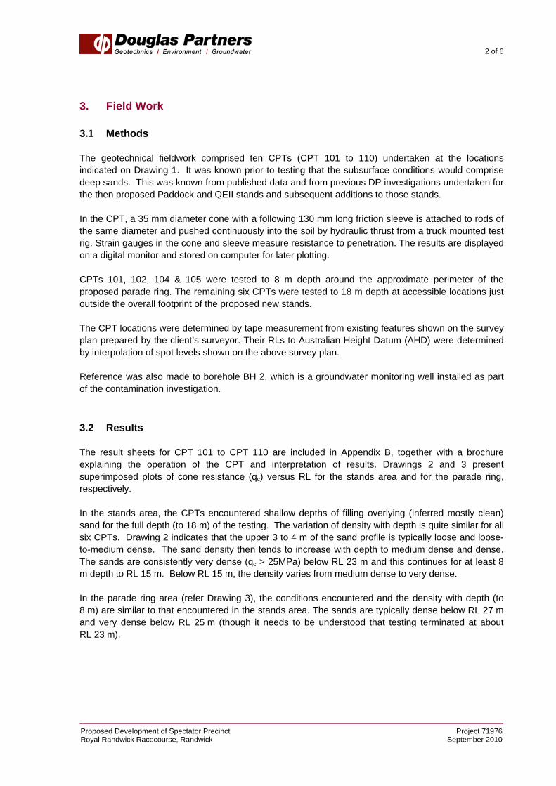
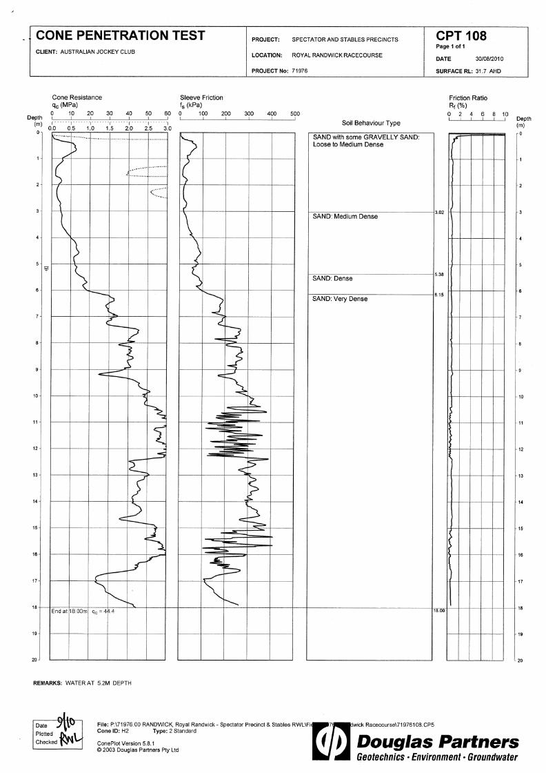
The geotechnical fieldwork comprised ten CPTs (CPT 101 to 110) undertaken at the locations indicated on Drawing 1. It was known prior to testing that the subsurface conditions would comprise deep sands. This was known from published data and from previous DP investigations undertaken for the then proposed Paddock and QEII stands and subsequent additions to those stands. In the CPT, a 35 mm diameter cone with a following 130 mm long friction sleeve is attached to rods of the same diameter and pushed continuously into the soil by hydraulic thrust from a truck mounted test rig. Strain gauges in the cone and sleeve measure resistance to penetration. The results are displayed on a digital monitor and stored on computer for later plotting. CPTs 101, 102, 104 & 105 were tested to 8 m depth around the approximate perimeter of the proposed parade ring. The remaining six CPTs were tested to 18 m depth at accessible locations just outside the overall footprint of the proposed new stands. The CPT locations were determined by tape measurement from existing features shown on the survey plan prepared by the client’s surveyor. Their RLs to Australian Height Datum (AHD) were determined by interpolation of spot levels shown on the above survey plan. Reference was also made to borehole BH 2, which is a groundwater monitoring well installed as part of the contamination investigation. 3.2 Results
The result sheets for CPT 101 to CPT 110 are included in Appendix B, together with a brochure explaining the operation of the CPT and interpretation of results. Drawings 2 and 3 present superimposed plots of cone resistance (qc) versus RL for the stands area and for the parade ring, respectively. In the stands area, the CPTs encountered shallow depths of filling overlying (inferred mostly clean) sand for the full depth (to 18 m) of the testing. The variation of density with depth is quite similar for all six CPTs. Drawing 2 indicates that the upper 3 to 4 m of the sand profile is typically loose and loose-to-medium dense. The sand density then tends to increase with depth to medium dense and dense. The sands are consistently very dense (qc > 25MPa) below RL 23 m and this continues for at least 8 m depth to RL 15 m. Below RL 15 m, the density varies from medium dense to very dense. In the parade ring area (refer Drawing 3), the conditions encountered and the density with depth (to 8 m) are similar to that encountered in the stands area. The sands are typically dense below RL 27 m and very dense below RL 25 m (though it needs to be understood that testing terminated at about RL 23 m).

3 of 6
Proposed Development of Spectator Precinct Project 71976Royal Randwick Racecourse, Randwick September 2010
3.3 Groundwater At the completion of each CPT, the cone rods were withdrawn and an attempt made to measure the depth to groundwater. This process is not always successful in sands because of collapse of the CPT hole. A water level measurement was also taken in BH 2. The results are summarised in Table 1. Table 1: Groundwater Level Measurements
Location Date Measured Ground Surface (RL m.AHD)
Depth to Water (m)
Water Level (RL m.AHD)
BH 2 3/09/10 32.0 5.3 26.7 CPT 101 30/08/10 32.0 5.5 26.5 CPT 102 27/08/10 32.1 5.9 26.2 CPT 103 27/08/10 29.3 2.9 26.4 CPT 107 30/08/10 31.2 4.5 26.7 CPT 108 30/08/10 31.7 5.2 26.5 CPT 109 30/08/10 31.5 5.1 26.4 CPT 110 30/08/10 31.4 5.2 26.2
Note: Groundwater level measurements made in a BH are typically more accurate than those made in a CPT hole. 4. Proposed Development
The proposed refurbishment of the Spectator Precinct involves the following features of relevance to geotechnical investigation:
• The Paddock Stand will be demolished and a replacement stand constructed. Large column loads will result from the new structure.
• Part of the footprint of the new stand will be occupied by basement areas of several metres depth. Part of the basement area will be at RL26.5 m, whereas part of the main service corridor will be at RL24.5 m.
• Structural modifications will be made to the existing QEII Stand, requiring the installation of some heavily loaded piles.
• A parade ring will be constructed in the area currently occupied by the Tea House and the lawn behind it. The parade ring will essentially involve an excavation to 4 m depth, with battered sideslopes for seating, and a three storey building at the southern end, represented by CPT 102 (refer Drawing 1).
• A tunnel for the passage of horses will be constructed from the parade ring to the existing race track, and will have a base level of RL27.5 m.
• There will of course be other, relatively minor civil and structural works such as localised cut and fill, retaining walls etc that need not be addressed in this general report.
The comments that follow are of a general and broad nature and have the purpose of flagging the main geotechnical issues that will need to be addressed at the detailed planning and design stages.

4 of 6
Proposed Development of Spectator Precinct Project 71976Royal Randwick Racecourse, Randwick September 2010
5. Comments
5.1 Proposed Stands
It is expected that the maximum column loads from the new and modified stands will be of substantial magnitude. (A maximum ultimate compression load of 20,000 kN has been tentatively indicated by the designer). The likely range of loads is currently uncertain. The major geotechnical issue in the Spectator Precinct is expected to be that of deciding the appropriate type of foundation to the stands. Considering the presence of loose sand in places within the upper 4 m, it is likely that major structural loads will be carried by piles. Design consideration could be given to the following pile types:
• Type (a) - cased bored piles founded on bedrock at depths in excess of 30 m. Depending on the conditions between the current depth (18 m) of CPT testing and the top of suitable bedrock (depth currently unknown), the use of large diameter (1200 mm) continuous flight auger (CFA) piles might also be suitable. It is DP’s understanding that a single 1200 mm diameter pile (using 70 MPa concrete) has the structural capacity to carry the above-mentioned large compression load.
• Type (b) - groups of say 900 mm diameter CFA piles founded in the thick stratum of very dense sand below about RL 23 m. Preliminary analysis indicates that such piles would have a Design Geotechnical Strength (Rg*) of a least 6000 kN. Hence a pile group of four piles might be required to carry the heaviest loads.
• Type (c) - driven, cast-in-situ, enlarged based piles (“Frankipiles”). Such piles were probably used in places for the existing stands. They could found at the top of the very dense sand stratum, and are capable of carrying large loads. Their method of construction, however, results in some large vibrations, which might be deemed unacceptable to adjacent structures.
• Type (d) - for more modest column loadings, consideration could be given to the use of Atlas piles, which are a proprietary cast-in-situ, concrete screw displacement pile. An Atlas pile in sand typically has a greater geotechnical strength than a CFA pile of comparable diameter and length, by virtue of it being a displacement pile rather than a bored pile, such as the CFA pile.
The main issues (apart from geotechnical and structural strengths) with whatever pile types are adopted will relate to constructability (e.g. vibrations, available headroom) and to the resultant settlements of piles and pile groups. The appropriate piling design will be determined at the detailed design phase of the project. 5.2 Basements and Tunnel
The geotechnical issues relating to the basement in the new stand, and to the new tunnel leading to the parade ring, are quite similar. The base slab levels of the basement and the tunnel range between RL26.5 m and RL27.5 m. The base slab level of the main service corridor will be RL24.5 m. These levels are either below or just above the recently measured groundwater level of RL26.7 m in BH2. Hence provision will need to be made for a ground water level continuously above the slab level of some areas of the basement, and possibly above the slab level in other areas during or after periods of prolonged rainfall.

5 of 6
Proposed Development of Spectator Precinct Project 71976Royal Randwick Racecourse, Randwick September 2010
Design consideration will need to be given to the following issues:
• The need for localised dewatering in places during construction.
• The need to ‘tank’ the structures so as to make them water-tight.
• The need for a method to overcome any resultant buoyancy forces. Tension piles in sand tend not to be very efficient and hence the use of deadweight might be more suitable. The latter should be readily achievable within the building basement, but might not be so readily achievable within the tunnel.
• The method of construction of the basement and tunnel walls. Several options are available:
− Seacant pile walls, cantilevered if possible during construction or else temporarily braced/anchored. Permanent bracing of the walls in the basement would be achieved by the ground level floor slab, and in the tunnel by the roof slab.
− Driven steel sheet piling with temporary anchors, and with the walls and base slab subsequently built in open space.
− If space permits, construction within an open excavation that has temporarily battered side slopes. The sideslopes would have to be no steeper than 1.5:1 (h:v) and hence the footprint of the excavation would be substantially larger than the final footprint of the basement or tunnel.
5.3 Parade Ring
Bulk excavation to 4 m depth for the parade ring will encounter a shallow depth of filling underlain by sand for the remaining depth of the excavation. Excavation will be readily achievable by use of conventional earth moving plant. The sides of the parade ring will be battered to allow the construction of tiered seating and standing areas around sections of the perimeter. Permanent batters in sand are typically constructed at slopes no steeper than 2:1 (h:v) provided there are no surcharge loads applied at the crest or on the batter. Vegetation of slopes and subsequent maintenance usually require batters no steeper than 3:1 (h:v). It is currently not known if the faces of the batters will be protected by concrete surfacing or revetment-like blockwork etc. Architectural requirements for the seating and standing areas call for overall slope batters of between 2:1 and 3:1 (h:v). Structural loads from the tiered seating and from crest structures will probably need to be supported on piles bearing in sand strata of suitable density at levels below the bulk excavation level. Driven timber piles or steel screw piles would be appropriate for support of the expected modest structural loads. Current groundwater level is at about 5.3 m depth below existing ground level. Hence if the base of the parade ring is at 4 metres depth, then it will be approximately 1.5 m above the current groundwater level. Rising groundwater levels would have to be expected after periods of prolonged rainfall. Design consideration will need to be given to whether the base of the ring needs to be tanked in some manner, or whether potential flooding of the base is acceptable. Additionally, the prepared subgrade to the ring will presumably comprise some imported and compacted material, overlain by turfed soil. Hence the ring surface is likely to be substantially less permeable than what it would be were the surface merely to comprise the natural in-situ sand. If this were to be the case, then a system of

6 of 6
Proposed Development of Spectator Precinct Project 71976Royal Randwick Racecourse, Randwick September 2010
perimeter drainage and pumpout pits might be required to remove ponded water resulting from heavy rainfall, even if the groundwater level has not risen. It is understood that a three storey Owners’ and Trainers’ Pavillion structure will be constructed at the southern end of the ring. The expected relatively modest column loads could be carried by Atlas piles (Pile Type (d) in Section 5.1) bearing in dense sand at say 6 m depth. Of the four CPTs undertaken for the parade ring, the poorest subsurface conditions were encountered in CPT 102. Preliminary pile analysis indicates that a 560/710 mm Atlas pile bearing at 6 m depth at CPT 102 would have a Design Geotechnical Strength (Rg*) of about 2200 kN. 5.4 Concluding Remarks
The broad geotechnical issues concerning the design and construction of the two stands, the basement and tunnel, and the parade ring have been addressed in this report. None of these issues are considered to be outside the normal range of issues routinely encountered on any relatively large comparable project. 6. Limitations
Douglas Partners (DP) has prepared this report for a project at Royal Randwick Racecourse, NSW in accordance with DP's proposal dated 13 August 2010 and 19 August 2010, and acceptance received from Mr Daniel Lacey of The AJC. The report is provided for the exclusive use of The AJC for this project only and for the purposes described in the report. It should not be used for other projects or by a third party. In preparing this report DP has necessarily relied upon information provided by the client and/or their agents. The results provided in the report are indicative of the sub-surface conditions only at the specific sampling or testing locations, and then only to the depths investigated and at the time the work was carried out. Sub-surface conditions can change abruptly due to variable geological processes and also as a result of anthropogenic influences. Such changes may occur after DP's field testing has been completed. DP's advice is based upon the conditions encountered during this investigation. The accuracy of the advice provided by DP in this report may be limited by undetected variations in ground conditions between sampling locations. The advice may also be limited by budget constraints imposed by others or by site accessibility. This report must be read in conjunction with all of the attached notes and should be kept in its entirety without separation of individual pages or sections. DP cannot be held responsible for interpretations or conclusions made by others unless they are supported by an expressed statement, interpretation, outcome or conclusion given in this report.
Douglas Partners Pty Ltd

Appendix A
About this Report

July 2010
Introduction These notes have been provided to amplify DP's report in regard to classification methods, field procedures and the comments section. Not all are necessarily relevant to all reports. DP's reports are based on information gained from limited subsurface excavations and sampling, supplemented by knowledge of local geology and experience. For this reason, they must be regarded as interpretive rather than factual documents, limited to some extent by the scope of information on which they rely. Copyright This report is the property of Douglas Partners Pty Ltd. The report may only be used for the purpose for which it was commissioned and in accordance with the Conditions of Engagement for the commission supplied at the time of proposal. Unauthorised use of this report in any form whatsoever is prohibited. Borehole and Test Pit Logs The borehole and test pit logs presented in this report are an engineering and/or geological interpretation of the subsurface conditions, and their reliability will depend to some extent on frequency of sampling and the method of drilling or excavation. Ideally, continuous undisturbed sampling or core drilling will provide the most reliable assessment, but this is not always practicable or possible to justify on economic grounds. In any case the boreholes and test pits represent only a very small sample of the total subsurface profile. Interpretation of the information and its application to design and construction should therefore take into account the spacing of boreholes or pits, the frequency of sampling, and the possibility of other than 'straight line' variations between the test locations. Groundwater Where groundwater levels are measured in boreholes there are several potential problems, namely: • In low permeability soils groundwater may
enter the hole very slowly or perhaps not at all during the time the hole is left open;
• A localised, perched water table may lead to an erroneous indication of the true water table;
• Water table levels will vary from time to time with seasons or recent weather changes. They may not be the same at the time of construction as are indicated in the report; and
• The use of water or mud as a drilling fluid will mask any groundwater inflow. Water has to be blown out of the hole and drilling mud must first be washed out of the hole if water measurements are to be made.
More reliable measurements can be made by installing standpipes which are read at intervals over several days, or perhaps weeks for low permeability soils. Piezometers, sealed in a particular stratum, may be advisable in low permeability soils or where there may be interference from a perched water table. Reports The report has been prepared by qualified personnel, is based on the information obtained from field and laboratory testing, and has been undertaken to current engineering standards of interpretation and analysis. Where the report has been prepared for a specific design proposal, the information and interpretation may not be relevant if the design proposal is changed. If this happens, DP will be pleased to review the report and the sufficiency of the investigation work. Every care is taken with the report as it relates to interpretation of subsurface conditions, discussion of geotechnical and environmental aspects, and recommendations or suggestions for design and construction. However, DP cannot always anticipate or assume responsibility for: • Unexpected variations in ground conditions.
The potential for this will depend partly on borehole or pit spacing and sampling frequency;
• Changes in policy or interpretations of policy by statutory authorities; or
• The actions of contractors responding to commercial pressures.
If these occur, DP will be pleased to assist with investigations or advice to resolve the matter.

July 2010
Site Anomalies In the event that conditions encountered on site during construction appear to vary from those which were expected from the information contained in the report, DP requests that it be immediately notified. Most problems are much more readily resolved when conditions are exposed rather than at some later stage, well after the event. Information for Contractual Purposes Where information obtained from this report is provided for tendering purposes, it is recommended that all information, including the written report and discussion, be made available. In circumstances where the discussion or comments section is not relevant to the contractual situation, it may be appropriate to prepare a specially edited document. DP would be pleased to assist in this regard and/or to make additional report copies available for contract purposes at a nominal charge. Site Inspection The company will always be pleased to provide engineering inspection services for geotechnical and environmental aspects of work to which this report is related. This could range from a site visit to confirm that conditions exposed are as expected, to full time engineering presence on site.

Appendix B
Results of Field Work


July 2010
Introduction The Cone Penetration Test (CPT) is a sophisticated soil profiling test carried out in-situ. A special cone shaped probe is used which is connected to a digital data acquisition system. The cone and adjoining sleeve section contain a series of strain gauges and other transducers which continuously monitor and record various soil parameters as the cone penetrates the soils. The soil parameters measured depend on the type of cone being used, however they always include the following basic measurements • Cone tip resistance qc • Sleeve friction fs • Inclination (from vertical) i • Depth below ground z Figure 1: Cone Diagram The inclinometer in the cone enables the verticality of the test to be confirmed and, if required, the vertical depth can be corrected. The cone is thrust into the ground at a steady rate of about 20 mm/sec, usually using the hydraulic rams of a purpose built CPT rig, or a drilling rig. The testing is carried out in accordance with the Australian Standard AS1289 Test 6.5.1.
Figure 2: Purpose built CPT rig The CPT can penetrate most soil types and is particularly suited to alluvial soils, being able to detect fine layering and strength variations. With sufficient thrust the cone can often penetrate a short distance into weathered rock. The cone will usually reach refusal in coarse filling, medium to coarse gravel and on very low strength or better rock. Tests have been successfully completed to more than 60 m. Types of CPTs Douglas Partners (and its subsidiary GroundTest) owns and operates the following types of CPT cones:
Type Measures Standard Basic parameters (qc, fs, i & z) Piezocone Dynamic pore pressure (u) plus
basic parameters. Dissipation tests estimate consolidation parameters
Conductivity Bulk soil electrical conductivity (σ) plus basic parameters
Seismic Shear wave velocity (Vs), compression wave velocity (Vp), plus basic parameters
Strata Interpretation The CPT parameters can be used to infer the Soil Behaviour Type (SBT), based on normalised values of cone resistance (Qt) and friction ratio (Fr). These are used in conjunction with soil classification charts, such as the one below (after Robertson 1990)

July 2010
Figure 3: Soil Classification Chart DP's in-house CPT software provides computer aided interpretation of soil strata, generating soil descriptions and strengths for each layer. The software can also produce plots of estimated soil parameters, including modulus, friction angle, relative density, shear strength and over consolidation ratio. DP's CPT software helps our engineers quickly evaluate the critical soil layers and then focus on developing practical solutions for the client's project. Engineering Applications There are many uses for CPT data. The main applications are briefly introduced below: Settlement CPT provides a continuous profile of soil type and strength, providing an excellent basis for settlement analysis. Soil compressibility can be estimated from cone derived moduli, or known consolidation parameters for the critical layers (eg. from laboratory testing). Further, if pore pressure dissipation tests are undertaken using a piezocone, in-situ consolidation coefficients can be estimated to aid analysis.
Pile Capacity The cone is, in effect, a small scale pile and, therefore, ideal for direct estimation of pile capacity. DP's in-house program ConePile can analyse most pile types and produces pile capacity versus depth plots. The analysis methods are based on proven static theory and empirical studies, taking account of scale effects, pile materials and method of installation. The results are expressed in limit state format, consistent with the Piling Code AS2159. Dynamic or Earthquake Analysis CPT and, in particular, Seismic CPT are suitable for dynamic foundation studies and earthquake response analyses, by profiling the low strain shear modulus G0. Techniques have also been developed relating CPT results to the risk of soil liquefaction. Other Applications Other applications of CPT include ground improvement monitoring (testing before and after works), salinity and contaminant plume mapping (conductivity cone), preloading studies and verification of strength gain. Figure 4: Sample Cone Plot

Drawings
Drawings 1, 2 and 3

CONC
PATH
PATH
PATH
PATH
CONC
CONC
CONC
BRICK
PAVING
BRICK
PAVING
CONC
PATH
BRICK
PAVING
BRICK
PAVING
GRASSED
AR EA
GRASSED
AREASOFT
PAVING
GARDEN
GARDEN
GARDEN
GARDEN
SOFT
PAVING
SOF
T
PAV
ING
UPPER S
TAND
MIDD LE
STAND
BRICK
PAVING
CONC
PATH
BRICKPAVING
CONCPATH
PAVING
GAR
DEN
GAR
DEN
BRI
CK
PAV
ING
TILE
D
STE
PS
RAMP
CARPETED
GRASSED GARDEN
T ILED
STEPS
GRA
SSED
AR
EA
SOF
T
PAV
ING
GARDEN
GARDEN
GARDEN
SOFT
PAVING
SOFT
PAVING
GAR
DEN
SO
FT
PA
VIN
G
SOFT
PAVING
CON
C
PAV
ING
GR
ASS
EDA
REA
PATH
GAR
DEN
R AMP
OF
OF
OF
STAND
STAND
STAND
RL 42.58
RL 46.40
RL 35.07
STAIRS
ROOF
RL 45.77
LINE
OF
GLASS
UNDERSIDE
OF
STAND
RL 35.05
TIMBE
R
BENC HES
TIMBER
BENCHES
MOVATORS
GRANDSTAND
BED
CON
C
LAWN
EDGE
OF
BITUMEN
PADDOCK
TEA
HOUSE
BRI
DGE
GAR DEN BED
ROUGH BR ICK
PAVING
BETTING
PAVILION
MOVATOR
MOVATOR
STE
PS
STE
PS
ES
CA
LATOR
S
ES
CA
LATOR
S
MOVATORS
MOVATORS STEPS
WINNERS AREA
HO
RSE
W
ALKW
AY
EDG E OF PAVING
TURNSTILES
BRICKPAVING
PAVINGBRICK
CONC
GRASSEDAREA
GRASSED
AREA
GRASSED
AREA
GRASSED
AREA
GRASSED
AREA
UND ERSIDE
UND ERSIDE
UND ERSIDE
BITUMEN
PAVED
PAVED
SURFACE
AREA
GRASSED
AREA
SOFT
PAVING
WA
LKW
AY
HEDGE & GARDEN
GRASSED
AREA
CONCRETE
97
EDGE PAVING
206°
07'40
"B
ITUM
ENC
ONC
RETE
GRASSED
AREAPAT
H
BIT
UMEN
CO
NCRE
TE
TUNNEL
31.000
GARDEN
TOILETS
BRICK
SEE
74163 "THE TEA HOUSE"
FOR 2010 SURVEY'S
SEE
74163
"THE PADDOCK"
FOR 2010
SURVEY'S
SEE
74163
"THE Q
E2 STAND"
FOR 2010
SURVEY'S
SEE
74163 "MEMBERS STAND"
FOR 2010 SURVEY'S
BRI
CK
PAV
ING
TUR
NTILES
IN
CO
VER
ED EN
TRY
GRASSED
AREA
BITUMEN
BITUMEN AREA
BIT
UM
EN
31.00
32.00
EXTENT OF SURVEYAUG/2010
QEII
106
101
102
103
104
105
107
108
109
110
BH2
LEGEND
DRAWING No:
PROJECT No: 71976
REVISION: B31.8.2010
CLIENT:
DRAWN BY:
APPROVED BY:
SCALE:
DATE:
OFFICE: SydneyPSCH As shown
Australian Jockey Club TITLE: Location of CPTs and Bore HoleSpectator PrecinctRoyal Randwick Racecourse, RANDWICK
1
LOCALITY PLAN
STABLES
SPECTATORPRECINCT
PRECINCT
P:\7
1976
.00
RAN
DW
ICK,
Roy
al R
andw
ick
- Sp
ecta
tor
Prec
inct
& S
tabl
es R
WL\
Dra
win
gs\7
1976
-1 R
evB.
dwg,
9/7
/201
0 11
:45:
35 A
M