Embed Size (px)
Citation preview
218
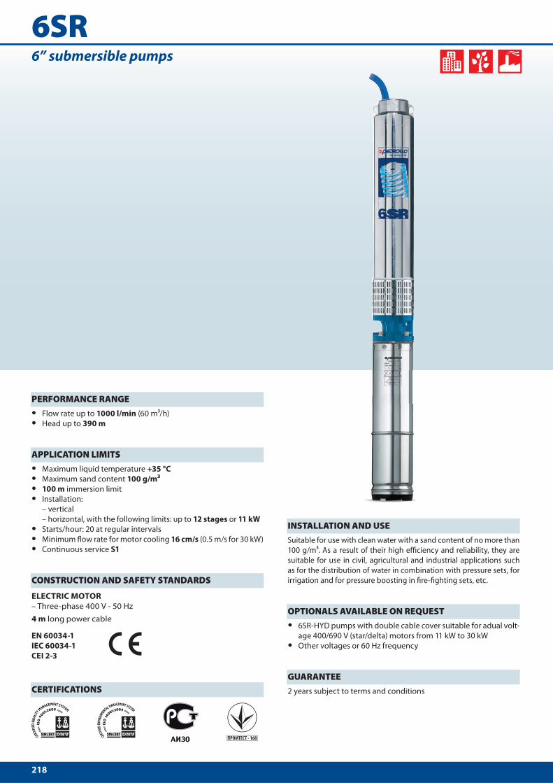
6SR6” submersible pumps
PERFORMANCE RANGE • Flow rate up to 1000 l/min (60 m³/h)
• Head up to 390 m
APPLICATION LIMITS • Maximum liquid temperature +35 °C
• Maximum sand content 100 g/m³
• 100 m immersion limit
• Installation:
– vertical
– horizontal, with the following limits: up to 12 stages or 11 kW
• Starts/hour: 20 at regular intervals
• Minimum fl ow rate for motor cooling 16 cm/s (0.5 m/s for 30 kW)
• Continuous service S1
CONSTRUCTION AND SAFETY STANDARDS
ELECTRIC MOTOR
– Three-phase 400 V - 50 Hz
4 m long power cable
EN 60034-1
IEC 60034-1
CEI 2-3
CERTIFICATIONS
INSTALLATION AND USESuitable for use with clean water with a sand content of no more than
100 g/m³. As a result of their high effi ciency and reliability, they are
suitable for use in civil, agricultural and industrial applications such
as for the distribution of water in combination with pressure sets, for
irrigation and for pressure boosting in fi re-fi ghting sets, etc.
OPTIONALS AVAILABLE ON REQUEST • 6SR-HYD pumps with double cable cover suitable for adual volt-
age 400/690 V (star/delta) motors from 11 kW to 30 kW
• Other voltages or 60 Hz frequency
GUARANTEE 2 years subject to terms and conditions
219
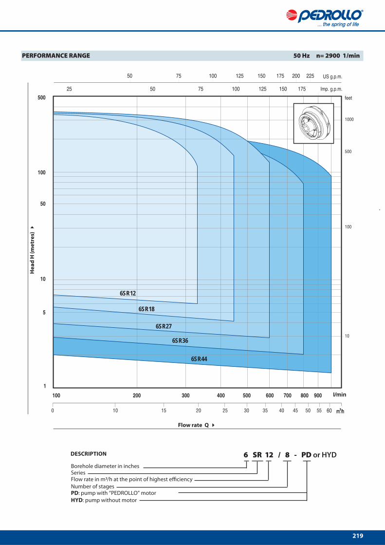
6SR12
6SR18
6SR27
6SR36
6SR44
Flow rate Q
He
ad
H (
me
tre
s)
PERFORMANCE RANGE 50 Hz n= 2900 1/min
Flow rate in m3/h at the point of highest effi ciencySeriesBorehole diameter in inches
6 SR 12 / 8 - PD or HYDDESCRIPTION
Number of stagesPD: pump with “PEDROLLO” motor
HYD: pump without motor

222
0 100 200 300 400 500 6000
50
100
150
200
250
300
350
400
0
100
200
300
400
500
600
700
800
900
100
1100
1200
0 20 40 60 80 100 120 140
0 20 40 60 80 100 120 140 160
0 5 10 15 20 25 30 35 40
56
41
=68%6SR27/27
6SR27/20
6SR27/17
6SR27/14
6SR27/12
6SR27/10
6SR27/8
6SR27/7
6SR27/5
6SR27/4
US g.p.m.
Imp g.p.m.
l/min
m³/h
feet
6SR27CHARACTERISTIC CURVES AND PERFORMANCE DATA 50 Hz n= 2900 1/min
Flow rate Q
He
ad
H (
me
tre
s)
Q = Flow rate H = Total manometric head Tolerance of characteristic curves in compliance with EN ISO 9906 App. A.
MODEL POWERQ
m³/h 0 6 12 18 24 30 36
Three-phase kW HP l/min 0 100 200 300 400 500 600
6SR27/4 4 5.5
H metres
54 53 49 45 40 30 18
6SR27/5 5.5 7.5 68 66 62 57 50 37 22
6SR27/7 7.5 10 95 92 87 80 70 52 31
6SR27/8 9.2 12.5 109 106 99 91 80 59 35
6SR27/10 11 15 136 132 124 114 100 74 44
6SR27/12 13 17.5 164 159 149 137 120 89 53
6SR27/14 15 20 191 185 174 160 140 104 62
6SR27/17 18.5 25 231 224 211 194 170 126 75
6SR27/20 22 30 272 264 248 228 200 148 88
6SR27/27 30 40 367 356 335 308 270 205 119
225
6SR
9
10
4
12
8 5
11
6 7
1
3
2
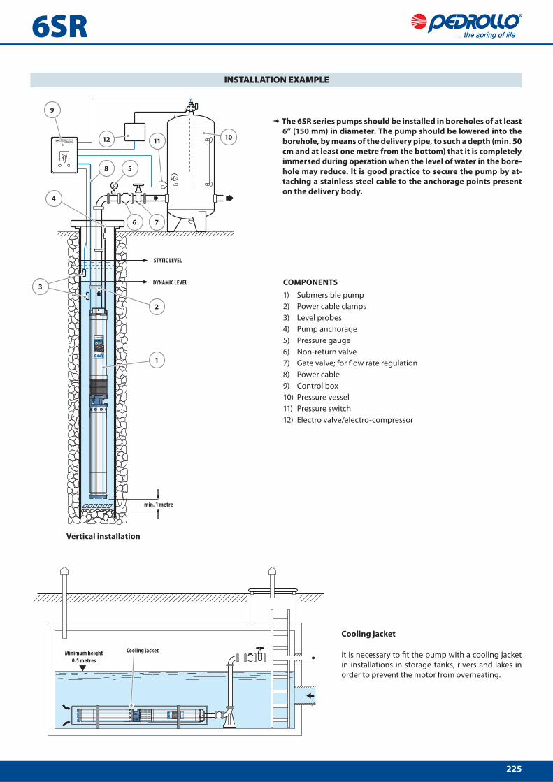
INSTALLATION EXAMPLE
COMPONENTS
1) Submersible pump
2) Power cable clamps
3) Level probes
4) Pump anchorage
5) Pressure gauge
6) Non-return valve
7) Gate valve; for fl ow rate regulation
8) Power cable
9) Control box
10) Pressure vessel
11) Pressure switch
12) Electro valve/electro-compressor
➠ The 6SR series pumps should be installed in boreholes of at least
6” (150 mm) in diameter. The pump should be lowered into the
borehole, by means of the delivery pipe, to such a depth (min. 50
cm and at least one metre from the bottom) that it is completely
immersed during operation when the level of water in the bore-
hole may reduce. It is good practice to secure the pump by at-
taching a stainless steel cable to the anchorage points present
on the delivery body.
Minimum height
0.5 metres
Cooling jacket
It is necessary to fi t the pump with a cooling jacket
in installations in storage tanks, rivers and lakes in
order to prevent the motor from overheating.
Vertical installation
STATIC LEVEL
DYNAMIC LEVEL
min. 1 metre
Cooling jacket
226
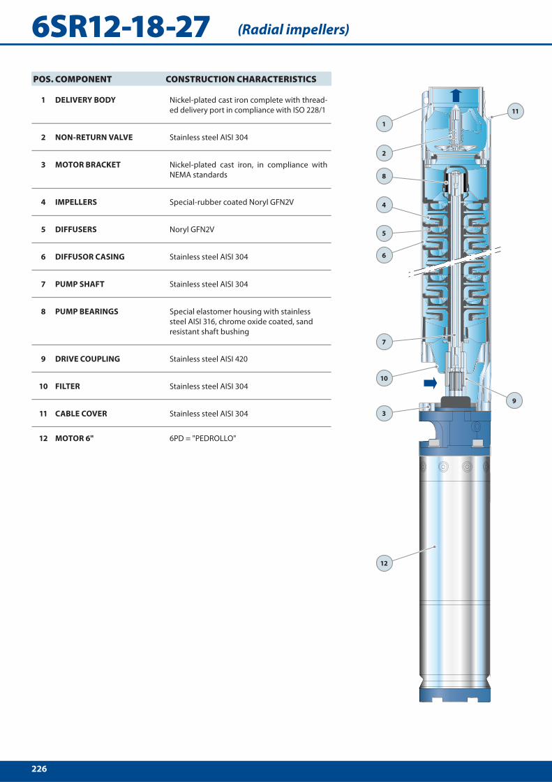
6SR12-18-27
1
2
8
4
5
11
6
9
7
3
12
10
POS. COMPONENT CONSTRUCTION CHARACTERISTICS
1 DELIVERY BODY Nickel-plated cast iron complete with thread-
ed delivery port in compliance with ISO 228/1
2 NON-RETURN VALVE Stainless steel AISI 304
3 MOTOR BRACKET Nickel-plated cast iron, in compliance with
NEMA standards
4 IMPELLERS Special-rubber coated Noryl GFN2V
5 DIFFUSERS Noryl GFN2V
6 DIFFUSOR CASING Stainless steel AISI 304
7 PUMP SHAFT Stainless steel AISI 304
8 PUMP BEARINGS Special elastomer housing with stainless
steel AISI 316, chrome oxide coated, sand
resistant shaft bushing
9 DRIVE COUPLING Stainless steel AISI 420
10 FILTER Stainless steel AISI 304
11 CABLE COVER Stainless steel AISI 304
12 MOTOR 6" 6PD = "PEDROLLO"
(Radial impellers)

228
6SR-PD
h1
Ø
DN
h2
h
Safety cable
anchorage point
DIMENSIONS AND WEIGHT
MODEL PORT DIMENSIONS mm kg
Three-phase DN Ø h1 h2 h 3~
6 SR 12/8 - PD
3" 149.5
719 633 1352 53.8
6 SR 12/11 - PD 849 667 1516 60.9
6 SR 12/15 - PD 1068 698 1766 66.8
6 SR 12/18 - PD 1198 731 1929 73.0
6 SR 12/21 - PD 1328 826 2154 83.9
6 SR 12/25 - PD 1502 894 2396 96.0
6 SR 12/28 - PD 1632 894 2526 98.1
6 SR 18/4 - PD 545 633 1178 49.6
6 SR 18/6 - PD 632 667 1299 53.6
6 SR 18/9 - PD 762 698 1460 60.3
6 SR 18/11 - PD 849 731 1580 67.0
6 SR 18/13 - PD 981 826 1807 76.9
6 SR 18/15 - PD 1068 894 1962 84.6
6 SR 18/18 - PD 1198 894 2092 87.6
6 SR 18/22 - PD 1371 959 2330 99.7
6 SR 18/26 - PD 1545 1116 2661 125.7
6 SR 27/4 - PD 583 633 1216 47.9
6 SR 27/5 - PD 636 667 1303 53.5
6 SR 27/7 - PD 742 698 1440 58.8
6 SR 27/8 - PD 795 731 1526 63.0
6 SR 27/10 - PD 901 826 1727 74.1
6 SR 27/12 - PD 1051 894 1945 83.6
6 SR 27/14 - PD 1157 894 2051 85.9
6 SR 27/17 - PD 1316 959 2275 97.5
6 SR 27/20 - PD 1474 1116 2590 123.0
6 SR 27/27 - PD 1845 1243 3088 135.8
6 SR 36/4 - PD 823 633 1456 55.4
6 SR 36/6 - PD 1049 667 1716 64.0
6 SR 36/8 - PD 1275 698 1973 71.0
6 SR 36/10 - PD 1501 731 2232 76.2
6 SR 36/11 - PD 1613 826 2439 90.0
6 SR 36/13 - PD 1839 894 2733 102.0
6 SR 36/15 - PD 2065 894 2959 107.0
6 SR 36/19 - PD 2517 959 3476 121.0
6 SR 36/23 - PD 2969 1116 4085 154.0
6 SR 44/3 - PD 710 633 1343 54.0
6 SR 44/4 - PD 823 667 1490 57.5
6 SR 44/5 - PD 936 698 1634 63.1
6 SR 44/6 - PD 1049 731 1780 70.0
6 SR 44/8 - PD 1275 826 2101 82.2
6 SR 44/9 - PD 1388 894 2282 92.0
6 SR 44/11 - PD 1613 894 2507 97.0
6 SR 44/13 - PD 1839 959 2798 110.0
6 SR 44/16 - PD 2178 1116 3294 141.0
6 SR 44/21 - PD 2743 1243 3986 154.3