Embed Size (px)
Citation preview
CHAPTER 4
GAS PIPING INSTALLATIONS
SECTION 401 (IFGC)GENERAL
401.1 Scope. This chapter shall govern the design, installation,modification and maintenance of piping systems. The applica-bility of this code to piping systems extends from the point ofdelivery to the connections with the equipment and includes thedesign, materials, components, fabrication, assembly, installa-tion, testing, inspection, operation and maintenance of suchpiping systems.
401.1.1 Utility piping systems located within buildings.Utility service piping located within buildings shall be in-stalled in accordance with the structural safety and fire pro-tection provisions of the International Building Code.
401.2 Liquefied petroleum gas storage. The storage systemfor liquefied petroleum gas shall be designed and installed inaccordance with the International Fire Code and NFPA 58.
401.3 Modifications to existing systems. In modifying or add-ing to existing piping systems, sizes shall be maintained in ac-cordance with this chapter.
401.4 Additional appliances. Where an additional applianceis to be served, the existing piping shall be checked to deter-mine if it has adequate capacity for all appliances served. If in-adequate, the existing system shall be enlarged as required orseparate piping of adequate capacity shall be provided.
401.5 Identification. For other than black steel pipe, exposedpiping shall be identified by a yellow label marked “Gas” inblack letters. The marking shall be spaced at intervals not ex-ceeding 5 feet (1524 mm). The marking shall not be required onpipe located in the same room as the equipment served.
401.6 Interconnections. Where two or more meters are in-stalled on the same premises but supply separate consumers,the piping systems shall not be interconnected on the outlet sideof the meters.
401.7 Piping meter identification. Piping from multiple me-ter installations shall be marked with an approved permanentidentification by the installer so that the piping system suppliedby each meter is readily identifiable.
401.8 Minimum sizes. All pipe utilized for the installation, ex-tension and alteration of any piping system shall be sized tosupply the full number of outlets for the intended purpose andshall be sized in accordance with Section 402.
SECTION 402 (IFGS)PIPE SIZING
402.1 General considerations. Piping systems shall be of suchsize and so installed as to provide a supply of gas sufficient tomeet the maximum demand without undue loss of pressure be-tween the point of delivery and the gas utilization equipment.
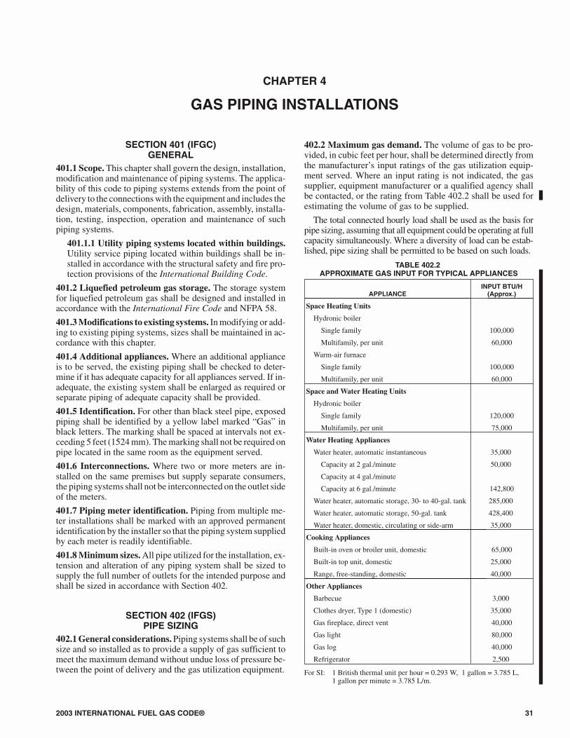
402.2 Maximum gas demand. The volume of gas to be pro-vided, in cubic feet per hour, shall be determined directly fromthe manufacturer’s input ratings of the gas utilization equip-ment served. Where an input rating is not indicated, the gassupplier, equipment manufacturer or a qualified agency shallbe contacted, or the rating from Table 402.2 shall be used forestimating the volume of gas to be supplied.
The total connected hourly load shall be used as the basis forpipe sizing, assuming that all equipment could be operating at fullcapacity simultaneously. Where a diversity of load can be estab-lished, pipe sizing shall be permitted to be based on such loads.
TABLE 402.2APPROXIMATE GAS INPUT FOR TYPICAL APPLIANCES
APPLIANCEINPUT BTU/H
(Approx.)
Space Heating Units
Hydronic boiler
Single family 100,000
Multifamily, per unit 60,000
Warm-air furnace
Single family 100,000
Multifamily, per unit 60,000
Space and Water Heating Units
Hydronic boiler
Single family 120,000
Multifamily, per unit 75,000
Water Heating Appliances
Water heater, automatic instantaneous 35,000
Capacity at 2 gal./minute 50,000
Capacity at 4 gal./minute
Capacity at 6 gal./minute 142,800
Water heater, automatic storage, 30- to 40-gal. tank 285,000
Water heater, automatic storage, 50-gal. tank 428,400
Water heater, domestic, circulating or side-arm 35,000
Cooking Appliances
Built-in oven or broiler unit, domestic 65,000
Built-in top unit, domestic 25,000
Range, free-standing, domestic 40,000
Other Appliances
Barbecue 3,000
Clothes dryer, Type 1 (domestic) 35,000
Gas fireplace, direct vent 40,000
Gas light 80,000
Gas log 40,000
Refrigerator 2,500
For SI: 1 British thermal unit per hour = 0.293 W, 1 gallon = 3.785 L,1 gallon per minute = 3.785 L/m.
2003 INTERNATIONAL FUEL GAS CODE® 31
GAS PIPING INSTALLATIONS
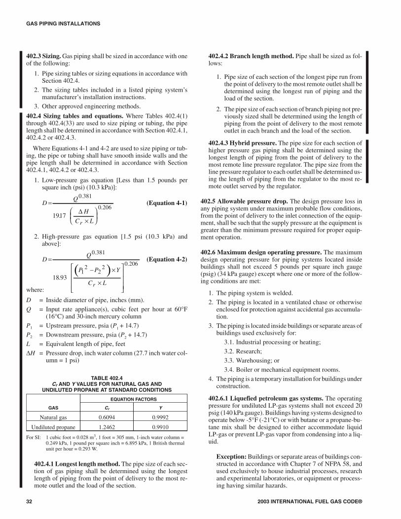
402.3 Sizing. Gas piping shall be sized in accordance with one of the following:
1. Pipe sizing tables or sizing equations in accordance with Section 402.4.
2. The sizing tables included in a listed piping system’s manufacturer’s installation instructions.
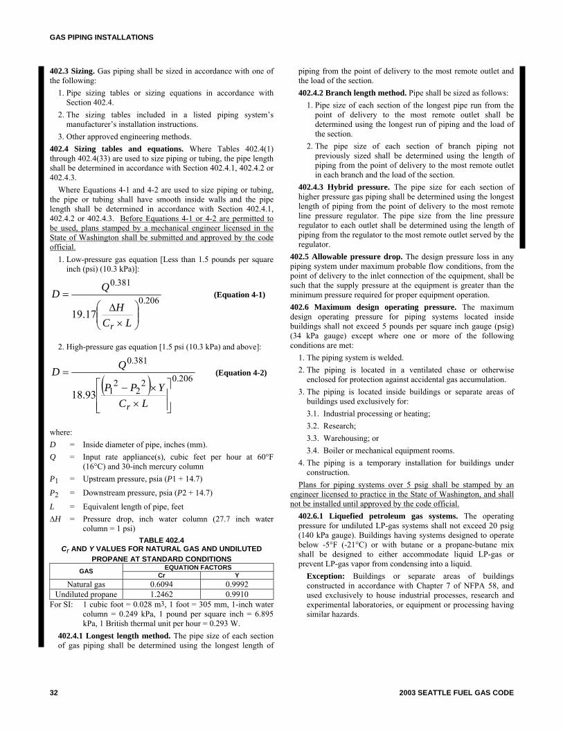
3. Other approved engineering methods. 402.4 Sizing tables and equations. Where Tables 402.4(1) through 402.4(33) are used to size piping or tubing, the pipe length shall be determined in accordance with Section 402.4.1, 402.4.2 or 402.4.3. Where Equations 4-1 and 4-2 are used to size piping or tubing, the pipe or tubing shall have smooth inside walls and the pipe length shall be determined in accordance with Section 402.4.1, 402.4.2 or 402.4.3. Before Equations 4-1 or 4-2 are permitted to be used, plans stamped by a mechanical engineer licensed in the State of Washington shall be submitted and approved by the code official.
1. Low-pressure gas equation [Less than 1.5 pounds per square inch (psi) (10.3 kPa)]:
206.0
381.0
17.19 ⎟⎟⎠
⎞⎜⎜⎝
⎛×
Δ=
LCH
QD
r
(Equation 4-1)
2. High-pressure gas equation [1.5 psi (10.3 kPa) and above]:
( ) 206.022
21
381.0
93.18⎥⎥⎦
⎤
⎢⎢⎣
⎡
××−
=
LCYPP
QD
r
(Equation 4-2)
where: D = Inside diameter of pipe, inches (mm). Q = Input rate appliance(s), cubic feet per hour at 60°F
(16°C) and 30-inch mercury column P1 = Upstream pressure, psia (P1 + 14.7)
P2 = Downstream pressure, psia (P2 + 14.7)
L = Equivalent length of pipe, feet ∆H = Pressure drop, inch water column (27.7 inch water
column = 1 psi) TABLE 402.4
Cr AND Y VALUES FOR NATURAL GAS AND UNDILUTED PROPANE AT STANDARD CONDITIONS
EQUATION FACTORS GAS Cr Y Natural gas 0.6094 0.9992
Undiluted propane 1.2462 0.9910 For SI: 1 cubic foot = 0.028 m3, 1 foot = 305 mm, 1-inch water
column = 0.249 kPa, 1 pound per square inch = 6.895 kPa, 1 British thermal unit per hour = 0.293 W.
402.4.1 Longest length method. The pipe size of each section of gas piping shall be determined using the longest length of
piping from the point of delivery to the most remote outlet and the load of the section. 402.4.2 Branch length method. Pipe shall be sized as follows:
1. Pipe size of each section of the longest pipe run from the point of delivery to the most remote outlet shall be determined using the longest run of piping and the load of the section.
2. The pipe size of each section of branch piping not previously sized shall be determined using the length of piping from the point of delivery to the most remote outlet in each branch and the load of the section.
402.4.3 Hybrid pressure. The pipe size for each section of higher pressure gas piping shall be determined using the longest length of piping from the point of delivery to the most remote line pressure regulator. The pipe size from the line pressure regulator to each outlet shall be determined using the length of piping from the regulator to the most remote outlet served by the regulator.
402.5 Allowable pressure drop. The design pressure loss in any piping system under maximum probable flow conditions, from the point of delivery to the inlet connection of the equipment, shall be such that the supply pressure at the equipment is greater than the minimum pressure required for proper equipment operation. 402.6 Maximum design operating pressure. The maximum design operating pressure for piping systems located inside buildings shall not exceed 5 pounds per square inch gauge (psig) (34 kPa gauge) except where one or more of the following conditions are met:
1. The piping system is welded. 2. The piping is located in a ventilated chase or otherwise
enclosed for protection against accidental gas accumulation. 3. The piping is located inside buildings or separate areas of
buildings used exclusively for: 3.1. Industrial processing or heating; 3.2. Research; 3.3. Warehousing; or 3.4. Boiler or mechanical equipment rooms.
4. The piping is a temporary installation for buildings under construction.
Plans for piping systems over 5 psig shall be stamped by an engineer licensed to practice in the State of Washington, and shall not be installed until approved by the code official.
402.6.1 Liquefied petroleum gas systems. The operating pressure for undiluted LP-gas systems shall not exceed 20 psig (140 kPa gauge). Buildings having systems designed to operate below -5°F (-21°C) or with butane or a propane-butane mix shall be designed to either accommodate liquid LP-gas or prevent LP-gas vapor from condensing into a liquid.
Exception: Buildings or separate areas of buildings constructed in accordance with Chapter 7 of NFPA 58, and used exclusively to house industrial processes, research and experimental laboratories, or equipment or processing having similar hazards.
32 2003 SEATTLE FUEL GAS CODE
2003 INTERNATIONAL FUEL GAS CODE® 33
GAS PIPING INSTALLATIONS
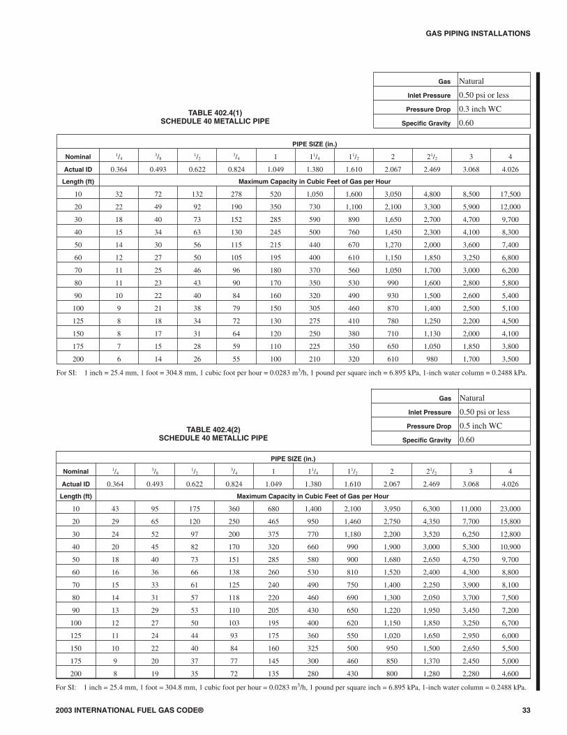
TABLE 402.4(1)SCHEDULE 40 METALLIC PIPE
Gas Natural
Inlet Pressure 0.50 psi or less
Pressure Drop 0.3 inch WC
Specific Gravity 0.60
PIPE SIZE (in.)
Nominal 1/43/8
1/23/4 1 11/4 11/2 2 21/2 3 4
Actual ID 0.364 0.493 0.622 0.824 1.049 1.380 1.610 2.067 2.469 3.068 4.026
Length (ft) Maximum Capacity in Cubic Feet of Gas per Hour
10 32 72 132 278 520 1,050 1,600 3,050 4,800 8,500 17,500
20 22 49 92 190 350 730 1,100 2,100 3,300 5,900 12,000
30 18 40 73 152 285 590 890 1,650 2,700 4,700 9,700
40 15 34 63 130 245 500 760 1,450 2,300 4,100 8,300
50 14 30 56 115 215 440 670 1,270 2,000 3,600 7,400
60 12 27 50 105 195 400 610 1,150 1,850 3,250 6,800
70 11 25 46 96 180 370 560 1,050 1,700 3,000 6,200
80 11 23 43 90 170 350 530 990 1,600 2,800 5,800
90 10 22 40 84 160 320 490 930 1,500 2,600 5,400
100 9 21 38 79 150 305 460 870 1,400 2,500 5,100
125 8 18 34 72 130 275 410 780 1,250 2,200 4,500
150 8 17 31 64 120 250 380 710 1,130 2,000 4,100
175 7 15 28 59 110 225 350 650 1,050 1,850 3,800
200 6 14 26 55 100 210 320 610 980 1,700 3,500
For SI: 1 inch = 25.4 mm, 1 foot = 304.8 mm, 1 cubic foot per hour = 0.0283 m3/h, 1 pound per square inch = 6.895 kPa, 1-inch water column = 0.2488 kPa.
TABLE 402.4(2)SCHEDULE 40 METALLIC PIPE
Gas Natural
Inlet Pressure 0.50 psi or less
Pressure Drop 0.5 inch WC
Specific Gravity 0.60
PIPE SIZE (in.)
Nominal 1/43/8
1/23/4 1 11/4 11/2 2 21/2 3 4
Actual ID 0.364 0.493 0.622 0.824 1.049 1.380 1.610 2.067 2.469 3.068 4.026
Length (ft) Maximum Capacity in Cubic Feet of Gas per Hour
10 43 95 175 360 680 1,400 2,100 3,950 6,300 11,000 23,000
20 29 65 120 250 465 950 1,460 2,750 4,350 7,700 15,800
30 24 52 97 200 375 770 1,180 2,200 3,520 6,250 12,800
40 20 45 82 170 320 660 990 1,900 3,000 5,300 10,900
50 18 40 73 151 285 580 900 1,680 2,650 4,750 9,700
60 16 36 66 138 260 530 810 1,520 2,400 4,300 8,800
70 15 33 61 125 240 490 750 1,400 2,250 3,900 8,100
80 14 31 57 118 220 460 690 1,300 2,050 3,700 7,500
90 13 29 53 110 205 430 650 1,220 1,950 3,450 7,200
100 12 27 50 103 195 400 620 1,150 1,850 3,250 6,700
125 11 24 44 93 175 360 550 1,020 1,650 2,950 6,000
150 10 22 40 84 160 325 500 950 1,500 2,650 5,500
175 9 20 37 77 145 300 460 850 1,370 2,450 5,000
200 8 19 35 72 135 280 430 800 1,280 2,280 4,600
For SI: 1 inch = 25.4 mm, 1 foot = 304.8 mm, 1 cubic foot per hour = 0.0283 m3/h, 1 pound per square inch = 6.895 kPa, 1-inch water column = 0.2488 kPa.
GAS PIPING INSTALLATIONS
34 2003 INTERNATIONAL FUEL GAS CODE®
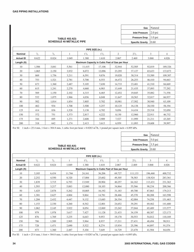
TABLE 402.4(3)SCHEDULE 40 METALLIC PIPE
Gas Natural
Inlet Pressure 2.0 psi
Pressure Drop 1.0 psi
Specific Gravity 0.60
PIPE SIZE (in.)
Nominal 1/23/4 1 11/4 11/2 2 21/2 3 4
Actual ID 0.622 0.824 1.049 1.380 1.610 2.067 2.469 3.068 4.026
Length (ft) Maximum Capacity in Cubic Feet of Gas per Hour
10 1,506 3,041 5,561 11,415 17,106 32,944 52,505 92,819 189,326
20 1,065 2,150 3,932 8,072 12,096 23,295 37,127 65,633 133,873
30 869 1,756 3,211 6,591 9,876 19,020 30,314 53,589 109,307
40 753 1,521 2,781 5,708 8,553 16,472 26,253 46,410 94,663
50 673 1,360 2,487 5,105 7,650 14,733 23,481 41,510 84,669
60 615 1,241 2,270 4,660 6,983 13,449 21,435 37,893 77,292
70 569 1,150 2,102 4,315 6,465 12,452 19,845 35,082 71,558
80 532 1,075 1,966 4,036 6,048 11,647 18,563 32,817 66,937
90 502 1,014 1,854 3,805 5,702 10,981 17,502 30,940 63,109
100 462 934 1,708 3,508 5,257 10,125 16,138 28,530 58,194
125 414 836 1,528 3,138 4,702 9,056 14,434 25,518 52,050
150 372 751 1,373 2,817 4,222 8,130 12,960 22,911 46,732
175 344 695 1,271 2,608 3,909 7,527 11,999 21,211 43,265
200 318 642 1,174 2,413 3,613 6,959 11,093 19,608 39,997
For SI: 1 inch = 25.4 mm, 1 foot = 304.8 mm, 1 cubic foot per hour = 0.0283 m3/h, 1 pound per square inch = 6.895 kPa.
TABLE 402.4(4)SCHEDULE 40 METALLIC PIPE
Gas Natural
Inlet Pressure 5.0 psi
Pressure Drop 3.5 psi
Specific Gravity 0.60
PIPE SIZE (in.)
Nominal 1/23/4 1 11/4 11/2 2 21/2 3 4
Actual ID 0.622 0.824 1.049 1.380 1.610 2.067 2.469 3.068 4.026
Length (ft) Maximum Capacity in Cubic Feet of Gas per Hour
10 3,185 6,434 11,766 24,161 36,206 69,727 111,133 196,468 400,732
20 2,252 4,550 8,320 17,084 25,602 49,305 78,583 138,924 283,361
30 1,839 3,715 6,793 13,949 20,904 40,257 64,162 113,431 231,363
40 1,593 3,217 5,883 12,080 18,103 34,864 55,566 98,234 200,366
50 1,425 2,878 5,262 10,805 16,192 31,183 49,700 87,863 179,213
60 1,301 2,627 4,804 9,864 14,781 28,466 45,370 80,208 163,598
70 1,204 2,432 4,447 9,132 13,685 26,354 42,004 74,258 151,463
80 1,153 2,330 4,260 8,542 12,801 24,652 39,291 69,462 141,680
90 1,062 2,145 3,922 8,054 12,069 23,242 37,044 65,489 133,577
100 979 1,978 3,617 7,427 11,128 21,433 34,159 60,387 123,173
125 876 1,769 3,235 6,643 9,953 19,170 30,553 54,012 110,169
150 786 1,589 2,905 5,964 8,937 17,211 27,431 48,494 98,911
175 728 1,471 2,690 5,522 8,274 15,934 25,396 44,897 91,574
200 673 1,360 2,487 5,104 7,649 14,729 23,478 41,504 84,656
For SI: 1 inch = 25.4 mm, 1 foot = 304.8 mm, 1 cubic foot per hour = 0.0283 m3/h, 1 pound per square inch = 6.895 kPa.
2003 INTERNATIONAL FUEL GAS CODE® 35
GAS PIPING INSTALLATIONS
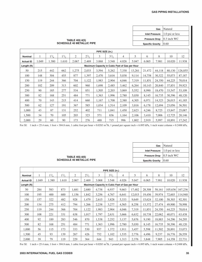
TABLE 402.4(6)SCHEDULE 40 METALLIC PIPE
Gas Natural
Inlet Pressure 1.0 psi or less
Pressure Drop 0.5 inch WC
Specific Gravity 0.60
PIPE SIZE (in.)
Nominal 1 11/4 11/2 2 21/2 3 31/2 4 5 6 8 10 12
Actual ID 1.049 1.380 1.610 2.067 2.469 3.068 3.548 4.026 5.047 6.065 7.981 10.020 11.938
Length (ft) Maximum Capacity in Cubic Feet of Gas per Hour
50 284 583 873 1,681 2,680 4,738 6,937 9,663 17,482 28,308 58,161 105,636 167,236
100 195 400 600 1,156 1,842 3,256 4,767 6,641 12,015 19,456 39,974 72,603 114,940
150 157 322 482 928 1,479 2,615 3,828 5,333 9,649 15,624 32,100 58,303 92,301
200 134 275 412 794 1,266 2,238 3,277 4,565 8,258 13,372 27,474 49,900 78,998
250 119 244 366 704 1,122 1,983 2,904 4,046 7,319 11,851 24,350 44,225 70,014
300 108 221 331 638 1,017 1,797 2,631 3,666 6,632 10,738 22,062 40,071 63,438
400 92 189 283 546 870 1,538 2,252 3,137 5,676 9,190 18,883 34,296 54,295
500 82 168 251 484 771 1,363 1,996 2,780 5,030 8,145 16,735 30,396 48,120
1,000 56 115 173 333 530 937 1,372 1,911 3,457 5,598 11,502 20,891 33,073
1,500 45 93 139 267 426 752 1,102 1,535 2,776 4,496 9,237 16,776 26,559
2,000 39 79 119 229 364 644 943 1,313 2,376 3,848 7,905 14,358 22,731
For SI: 1 inch = 25.4 mm, 1 foot = 304.8 mm, 1 cubic foot per hour = 0.0283 m3/h, 1 pound per square inch = 6.895 kPa, 1-inch water column = 0.2488 kPa.
TABLE 402.4(5)SCHEDULE 40 METALLIC PIPE
Gas Natural
Inlet Pressure 1.0 psi or less
Pressure Drop 0.3 inch WC
Specific Gravity 0.60
PIPE SIZE (in.)
Nominal 1 11/4 11/2 2 21/2 3 31/2 4 5 6 8 10 12
Actual ID 1.049 1.380 1.610 2.067 2.469 3.068 3.548 4.026 5.047 6.065 7.981 10.020 11.938
Length (ft) Maximum Capacity in Cubic Feet of Gas per Hour
50 215 442 662 1,275 2,033 3,594 5,262 7,330 13,261 21,472 44,118 80,130 126,855
100 148 304 455 877 1,397 2,470 3,616 5,038 9,114 14,758 30,322 55,073 87,187
150 119 244 366 704 1,122 1,983 2,904 4,046 7,319 11,851 24,350 44,225 70,014
200 102 209 313 602 960 1,698 2,485 3,462 6,264 10,143 20,840 37,851 59,923
250 90 185 277 534 851 1,505 2,203 3,069 5,552 8,990 18,470 33,547 53,109
300 82 168 251 484 771 1,363 1,996 2,780 5,030 8,145 16,735 30,396 48,120
400 70 143 215 414 660 1,167 1,708 2,380 4,305 6,971 14,323 26,015 41,185
500 62 127 191 367 585 1,034 1,514 2,109 3,816 6,178 12,694 23,056 36,501
1,000 43 87 131 252 402 711 1,041 1,450 2,623 4,246 8,725 15,847 25,087
1,500 34 70 105 203 323 571 836 1,164 2,106 3,410 7,006 12,725 20,146
2,000 29 60 90 173 276 488 715 996 1,802 2,919 5,997 10,891 17,242
For SI: 1 inch = 25.4 mm, 1 foot = 304.8 mm, 1 cubic foot per hour = 0.0283 m3/h, 1 pound per square inch = 6.895 kPa, 1-inch water column = 0.2488 kPa.

GAS PIPING INSTALLATIONS
36 2003 INTERNATIONAL FUEL GAS CODE®
TABLE 402.4(7)SEMI-RIGID COPPER TUBING
Gas Natural
Inlet Pressure 0.5 psi or less
Pressure Drop 0.3 inch WC
Specific Gravity 0.60
TUBE SIZE (in.)
NominalK & L 1/4
3/81/2
5/83/4 1 11/4 11/2 2 21/2
ACR 3/81/2
5/83/4
7/8 11/8 13/8 15/8 21/8 25/8
Outside 0.375 0.500 0.625 0.750 0.875 1.125 1.375 1.625 2.125 2.625
Inside 0.305 0.402 0.527 0.652 0.745 0.995 1.245 1.481 1.959 2.435
Length (ft) Maximum Capacity in Cubic Feet of Gas per Hour
10 20 42 85 148 210 448 806 1,271 2,646 4,682
20 14 29 58 102 144 308 554 873 1,819 3,218
30 11 23 47 82 116 247 445 701 1,461 2,584
40 10 20 40 70 99 211 381 600 1,250 2,212
50 8.4 17 35 62 88 187 337 532 1,108 1,960
60 7.6 16 32 56 79 170 306 482 1,004 1,776
70 7.0 14 29 52 73 156 281 443 924 1,634
80 6.5 13 27 48 68 145 262 413 859 1,520
90 6.1 13 26 45 64 136 245 387 806 1,426
100 5.8 12 24 43 60 129 232 366 761 1,347
125 5.1 11 22 38 53 114 206 324 675 1,194
150 4.7 10 20 34 48 103 186 294 612 1,082
175 4.3 8.8 18 31 45 95 171 270 563 995
200 4.0 8.2 17 29 41 89 159 251 523 926
250 3.5 7.3 15 26 37 78 141 223 464 821
300 3.2 6.6 13 23 33 71 128 202 420 744
Note: Table capacities are based on Type K copper tubing inside diameter (shown), which has the smallest inside diameter of the copper tubing products.For SI: 1 inch = 25.4 mm, 1 foot = 304.8 mm, 1 cubic foot per hour = 0.0283 m3/h, 1 pound per square inch = 6.895 kPa, 1-inch water column = 0.2488 kPa.

2003 INTERNATIONAL FUEL GAS CODE® 37
GAS PIPING INSTALLATIONS
TABLE 402.4(8)SEMI-RIGID COPPER TUBING
Gas Natural
Inlet Pressure 0.5 psi or less
Pressure Drop 0.5 inch WC
Specific Gravity 0.60
TUBE SIZE (in.)
NominalK & L 1/4
3/81/2
5/83/4 1 11/4 11/2 2 21/2
ACR 3/81/2
5/83/4
7/8 11/8 13/8 15/8 21/8 25/8
Outside 0.375 0.500 0.625 0.750 0.875 1.125 1.375 1.625 2.125 2.625
Inside 0.305 0.402 0.527 0.652 0.745 0.995 1.245 1.481 1.959 2.435
Length (ft) Maximum Capacity in Cubic Feet of Gas per Hour
10 27 55 111 195 276 590 1,062 1,675 3,489 6,173
20 18 38 77 134 190 406 730 1,151 2,398 4,242
30 15 30 61 107 152 326 586 925 1,926 3,407
40 13 26 53 92 131 279 502 791 1,648 2,916
50 11 23 47 82 116 247 445 701 1,461 2,584
60 10 21 42 74 105 224 403 635 1,323 2,341
70 9.3 19 39 68 96 206 371 585 1,218 2,154
80 8.6 18 36 63 90 192 345 544 1,133 2,004
90 8.1 17 34 59 84 180 324 510 1,063 1,880
100 7.6 16 32 56 79 170 306 482 1,004 1,776
125 6.8 14 28 50 70 151 271 427 890 1,574
150 6.1 13 26 45 64 136 245 387 806 1,426
175 5.6 12 24 41 59 125 226 356 742 1,312
200 5.2 11 22 39 55 117 210 331 690 1,221
250 4.7 10 20 34 48 103 186 294 612 1,082
300 4.2 8.7 18 31 44 94 169 266 554 980
Note: Table capacities are based on Type K copper tubing inside diameter (shown), which has the smallest inside diameter of the copper tubing products.For SI: 1 inch = 25.4 mm, 1 foot = 304.8 mm, 1 cubic foot per hour = 0.0283 m3/h, 1 pound per square inch = 6.895 kPa, 1-inch water column = 0.2488 kPa.
301.15 Prohibited location. The appliances, equipment andsystems regulated by this code shall not be located in an eleva-tor shaft.
SECTION 302 (IFGC)STRUCTURAL SAFETY
[B] 302.1 Structural safety. The building shall not be weak-ened by the installation of any gas piping. In the process of in-stalling or repairing any gas piping, the finished floors, walls,ceilings, tile work or any other part of the building or premiseswhich is required to be changed or replaced shall be left in asafe structural condition in accordance with the requirementsof the International Building Code.
[B] 302.2 Penetrations of floor/ceiling assemblies andfire-resistance-rated assemblies. Penetrations of floor/ceil-ing assemblies and assemblies required to have a fire-resis-tance rating shall be protected in accordance with theInternational Building Code.
[B] 302.3 Cutting, notching and boring in wood members.The cutting, notching and boring of wood members shall com-ply with Sections 302.3.1 through 302.3.4.
[B] 302.3.1 Engineered wood products. Cuts, notches andholes bored in trusses, laminated veneer lumber, glued-lam-inated members and I-joists are prohibited except where theeffects of such alterations are specifically considered in thedesign of the member.
[B] 302.3.2 Joist notching. Notching at the ends of joistsshall not exceed one-fourth the joist depth. Holes bored injoists shall not be within 2 inches (51 mm) of the top andbottom of the joist and their diameter shall not exceedone-third the depth of the member. Notches in the top or bot-tom of the joist shall not exceed one-sixth the depth andshall not be located in the middle one-third of the span.
[B] 302.3.3 Stud cutting and notching. In exterior wallsand bearing partitions, any wood stud is permitted to be cutor notched to a depth not exceeding 25 percent of its width.Cutting or notching of studs to a depth not greater than 40percent of the width of the stud is permitted innonload-bearing partitions supporting no loads other thanthe weight of the partition.
[B] 302.3.4 Bored holes. A hole not greater in diameter than40 percent of the stud depth is permitted to be bored in anywood stud. Bored holes not greater than 60 percent of thedepth of the stud are permitted in nonload-bearing partitionsor in any wall where each bored stud is doubled, providednot more than two such successive doubled studs are sobored. In no case shall the edge of the bored hole be nearerthan 5/8 inch (15.9 mm) to the edge of the stud. Bored holesshall not be located at the same section of stud as a cut ornotch.
[B] 302.4 Alterations to trusses. Truss members and compo-nents shall not be cut, drilled, notched, spliced or otherwise al-tered in any way without the written concurrence and approvalof a registered design professional. Alterations resulting in theaddition of loads to any member (e.g., HVAC equipment, waterheaters) shall not be permitted without verification that thetruss is capable of supporting such additional loading.
[B] 302.5 Cutting, notching and boring holes in structuralsteel framing. The cutting, notching and boring of holes instructural steel framing members shall be as prescribed by theregistered design professional.
[B] 302.6 Cutting, notching and boring holes incold-formed steel framing. Flanges and lips of load-bearing,cold-formed steel framing members shall not be cut or notched.Holes in webs of load-bearing, cold-formed steel framingmembers shall be permitted along the centerline of the web ofthe framing member and shall not exceed the dimensional limi-tations, penetration spacing or minimum hole edge distance asprescribed by the registered design professional. Cutting,notching and boring holes of steel floor/roof decking shall be asprescribed by the registered design professional.
[B] 302.7 Cutting, notching and boring holes innonstructural cold-formed steel wall framing. Flanges andlips of nonstructural cold-formed steel wall studs shall be per-mitted along the centerline of the web of the framing member,shall not exceed 11/2 inches (38 mm) in width or 4 inches (102mm) in length, and the holes shall not be spaced less than 24inches (610 mm) center to center from another hole or less than10 inches (254 mm) from the bearing end.
SECTION 303 (IFGC)APPLIANCE LOCATION
303.1 General. Appliances shall be located as required by thissection, specific requirements elsewhere in this code and theconditions of the equipment and appliance listing.
303.2 Hazardous locations. Appliances shall not be located ina hazardous location unless listed and approved for the specificinstallation.
303.3 Prohibited locations. Appliances shall not be located in,or obtain combustion air from, any of the following rooms orspaces:
1. Sleeping rooms.
2. Bathrooms.
3. Toilet rooms.
4. Storage closets.
5. Surgical rooms.
Exceptions:
1. Direct-vent appliances that obtain all combustion airdirectly from the outdoors.
2. Vented room heaters, wall furnaces, vented decorativeappliances and decorative appliances for installationin vented solid fuel-burning fireplaces, provided thatthe room meets the required volume criteria of Sec-tion 304.5.
3. A single wall-mounted unvented room heaterequipped with an oxygen depletion safety shutoff sys-tem and installed in a bathroom, provided that the in-put rating does not exceed 6,000 Btu/h (1.76kW) andthe bathroom meets the required volume criteria ofSection 304.5.
4. A single wall-mounted unvented room heaterequipped with an oxygen depletion safety shutoff sys-
GENERAL REGULATIONS
20 2003 INTERNATIONAL FUEL GAS CODE®
tem and installed in a bedroom, provided that the in-put rating does not exceed 10,000 Btu/h (2.93 kW)and the bedroom meets the required volume criteria ofSection 304.5.
5. Appliances installed in an enclosure in which all com-bustion air is taken from the outdoors, in accordancewith Section 304.6. Access to such enclosure shall bethrough a solid weather-stripped door, equipped withan approved self-closing device.
303.4 Protection from physical damage. Appliances shall notbe installed in a location where subject to physical damage un-less protected by approved barriers meeting the requirementsof the International Fire Code.
303.5 Indoor locations. Furnaces and boilers installed in clos-ets and alcoves shall be listed for such installation.
303.6 Outdoor locations. Equipment installed in outdoor lo-cations shall be either listed for outdoor installation or providedwith protection from outdoor environmental factors that influ-ence the operability, durability and safety of the equipment.
303.7 Pit locations. Appliances installed in pits or excavationsshall not come in direct contact with the surrounding soil. Thesides of the pit or excavation shall be held back a minimum of12 inches (305 mm) from the appliance. Where the depth ex-ceeds 12 inches (305 mm) below adjoining grade, the walls ofthe pit or excavation shall be lined with concrete or masonry,such concrete or masonry shall extend a minimum of 4 inches(102 mm) above adjoining grade and shall have sufficient lat-eral load-bearing capacity to resist collapse. The applianceshall be protected from flooding in an approved manner.
SECTION 304 (IFGS)COMBUSTION, VENTILATION AND DILUTION AIR
304.1 General. Air for combustion, ventilation and dilution offlue gases for gas utilization equipment installed in buildingsshall be provided by application of one of the methods pre-scribed in Sections 304.5 through 304.9. Where the require-ments of Section 304.5 are not met, outdoor air shall beintroduced in accordance with one of the methods prescribed inSections 304.6 through 304.9. Direct-vent appliances, gas ap-pliances of other than natural draft design and vented gas appli-ances other than Category I shall be provided with combustion,ventilation and dilution air in accordance with the equipmentmanufacturer’s instructions.
Exception: Type 1 clothes dryers that are provided withmakeup air in accordance with Section 614.5.
304.2 Appliance/equipment location. Equipment shall be lo-cated so as not to interfere with proper circulation of combus-tion, ventilation and dilution air.
304.3 Draft hood/regulator location. Where used, a drafthood or a barometric draft regulator shall be installed in thesame room or enclosure as the equipment served so as to pre-vent any difference in pressure between the hood or regulatorand the combustion air supply.
304.4 Makeup air provisions. Makeup air requirements forthe operation of exhaust fans, kitchen ventilation systems,
clothes dryers and fireplaces shall be considered in determiningthe adequacy of a space to provide combustion air requirements.
304.5 Indoor combustion air. The required volume of indoorair shall be determined in accordance with Section 304.5.1 or304.5.2, except that where the air infiltration rate is known to beless than 0.40 air changes per hour (ACH), Section 304.5.2shall be used. The total required volume shall be the sum of therequired volume calculated for all appliances located withinthe space. Rooms communicating directly with the space inwhich the appliances are installed through openings not fur-nished with doors, and through combustion air openings sizedand located in accordance with Section 304.5.3, are consideredto be part of the required volume.
304.5.1 Standard method. The minimum required volumeshall be 50 cubic feet per 1,000 Btu/h (4.8 m3/kW) of the ap-pliance input rating.
304.5.2 Known air-infiltration-rate method. Where theair infiltration rate of a structure is known, the minimum re-quired volume shall be determined as follows:
For appliances other than fan-assisted, calculate volumeusing Equation 3-1.
Required Volumeother ≥
21
1 000
3ft
ACH
I
B u hrother
, /t
(Equation 3-1)
For fan-assisted appliances, calculate volume usingEquation 3-2.
Required Volumefan ≥
15
1 000
3ft
ACH
I
B u hrfan
, /t
(Equation 3-2)where:
Iother = All appliances other than fan assisted (input inBtu/h).
Ifan = Fan-assisted appliance (input in Btu/h).
ACH = Air change per hour (percent of volume of spaceexchanged per hour, expressed as a decimal).
For purposes of this calculation, an infiltration rategreater than 0.60 ACH shall not be used in Equations 3-1and 3-2.
304.5.3 Indoor opening size and location. Openings usedto connect indoor spaces shall be sized and located in accor-dance with Sections 304.5.3.1 and 304.5.3.2 (see Figure304.5.3).
304.5.3.1 Combining spaces on the same story. Eachopening shall have a minimum free area of 1 square inchper 1,000 Btu/h (2,200 mm2/kW) of the total input ratingof all gas utilization equipment in the space, but not lessthan 100 square inches (0.06 m2). One opening shallcommence within 12 inches (305 mm) of the top and oneopening shall commence within 12 inches (305 mm) ofthe bottom of the enclosure. The minimum dimension ofair openings shall be not less than 3 inches (76 mm).
304.5.3.2 Combining spaces in different stories. Thevolumes of spaces in different stories shall be consideredas communicating spaces where such spaces are con-
2003 INTERNATIONAL FUEL GAS CODE® 21
GENERAL REGULATIONS
�
�
nected by one or more openings in doors or floors havinga total minimum free area of 2 square inches per 1,000Btu/h (4402 mm2/kW) of total input rating of all gas utili-zation equipment.
304.6 Outdoor combustion air. Outdoor combustion air shallbe provided through opening(s) to the outdoors in accordancewith Section 304.6.1 or 304.6.2. The minimum dimension ofair openings shall be not less than 3 inches (76 mm).
304.6.1 Two-permanent-openings method. Two perma-nent openings, one commencing within 12 inches (305 mm)of the top and one commencing within 12 inches (305 mm)of the bottom of the enclosure, shall be provided. The open-ings shall communicate directly, or by ducts, with the out-doors or spaces that freely communicate with the outdoors.
Where directly communicating with the outdoors, orwhere communicating with the outdoors through verticalducts, each opening shall have a minimum free area of 1square inch per 4,000 Btu/h (550 mm2/kW) of total inputrating of all equipment in the enclosure [see Figures304.6.1(1) and 304.6.1(2)].
Where communicating with the outdoors through hori-zontal ducts, each opening shall have a minimum free areaof not less than 1 square inch per 2,000 Btu/h (1,100mm2/kW) of total input rating of all equipment in the enclo-sure [see Figure 304.6.1(3)].
304.6.2 One-permanent-opening method. One perma-nent opening, commencing within 12 inches (305 mm) ofthe top of the enclosure, shall be provided. The equipmentshall have clearances of at least 1 inch (25 mm) from thesides and back and 6 inches (152 mm) from the front of theappliance. The opening shall directly communicate with theoutdoors or through a vertical or horizontal duct to the out-doors or spaces that freely communicate with the outdoors[see Figure 304.6.2] and shall have a minimum free area of 1square inch per 3,000 Btu/h (734 mm2/kW) of the total inputrating of all equipment located in the enclosure, and not lessthan the sum of the areas of all vent connectors in the space.
304.7 Combination indoor and outdoor combustion air.The use of a combination of indoor and outdoor combustion airshall be in accordance with Sections 304.7.1 through 304.7.3.
304.7.1 Indoor openings. Where used, openings connect-ing the interior spaces shall comply with Section 304.5.3.
304.7.2 Outdoor opening location. Outdoor opening(s)shall be located in accordance with Section 304.6.
304.7.3 Outdoor opening(s) size. The outdoor opening(s)size shall be calculated in accordance with the following:
1. The ratio of interior spaces shall be the available vol-ume of all communicating spaces divided by the re-quired volume.
2. The outdoor size reduction factor shall be one minusthe ratio of interior spaces.
3. The minimum size of outdoor opening(s) shall be thefull size of outdoor opening(s) calculated in accor-dance with Section 304.6, multiplied by the reductionfactor. The minimum dimension of air openings shallbe not less than 3 inches (76 mm).
304.8 Engineered installations. Engineered combustion airinstallations shall provide an adequate supply of combustion,ventilation and dilution air and shall be approved.
304.9 Mechanical combustion air supply. Where all combus-tion air is provided by a mechanical air supply system, the com-bustion air shall be supplied from the outdoors at a rate not lessthan 0.35 cubic feet per minute per 1,000 Btu/h (0.034 m3/minper kW) of total input rating of all appliances located within thespace.
304.9.1 Makeup air. Where exhaust fans are installed,makeup air shall be provided to replace the exhausted air.
304.9.2 Appliance interlock. Each of the appliances servedshall be interlocked with the mechanical air supply systemto prevent main burner operation when the mechanical airsupply system is not in operation.
304.9.3 Combined combustion air and ventilation airsystem. Where combustion air is provided by the building’smechanical ventilation system, the system shall provide thespecified combustion air rate in addition to the required ven-tilation air.
304.10 Louvers and grilles. The required size of openings forcombustion, ventilation and dilution air shall be based on thenet free area of each opening. Where the free area through a de-sign of louver or grille is known, it shall be used in calculatingthe size opening required to provide the free area specified.Where the design and free area are not known, it shall be as-sumed that wood louvers will have 25-percent free area andmetal louvers and grilles will have 75-percent free area.Nonmotorized louvers and grilles shall be fixed in the open po-sition. Motorized louvers shall be interlocked with the equip-ment so that they are proven to be in the full open position priorto main burner ignition and during main burner operation.Means shall be provided to prevent the main burner from ignit-ing if the louvers fail to open during burner start-up and to shutdown the main burner if the louvers close during operation.
304.11 Combustion air ducts. Combustion air ducts shallcomply with all of the following:
1. Ducts shall be of galvanized steel complying with Chap-ter 6 of the International Mechanical Code or of equiva-lent corrosion-resistant material approved for thisapplication.
Exception: Within dwellings units, unobstructed studand joist spaces shall not be prohibited from convey-ing combustion air, provided that not more than onerequired fireblock is removed.
2. Ducts shall terminate in an unobstructed space allowingfree movement of combustion air to the appliances.
3. Ducts shall serve a single enclosure.
4. Ducts shall not serve both upper and lower combustionair openings where both such openings are used. The sep-aration between ducts serving upper and lower combus-tion air openings shall be maintained to the source ofcombustion air.
5. Ducts shall not be screened where terminating in an atticspace.
GENERAL REGULATIONS
22 2003 INTERNATIONAL FUEL GAS CODE®
�

6. Horizontal upper combustion air ducts shall not slopedownward toward the source of combustion air.
7. The remaining space surrounding a chimney liner, gasvent, special gas vent or plastic piping installed within amasonry, metal or factory-built chimney shall not beused to supply combustion air.
Exception: Direct-vent gas-fired appliances de-signed for installation in a solid fuel-burning fireplacewhere installed in accordance with the listing and themanufacturer’s instructions.
8. Combustion air intake openings located on the exterior ofa building shall have the lowest side of such openings lo-cated not less than 12 inches (305 mm) vertically fromthe adjoining grade level.
304.12 Protection from fumes and gases. Where corrosive orflammable process fumes or gases, other than products of com-bustion, are present, means for the disposal of such fumes orgases shall be provided. Such fumes or gases include carbonmonoxide, hydrogen sulfide, ammonia, chlorine andhalogenated hydrocarbons.
In barbershops, beauty shops and other facilities wherechemicals that generate corrosive or flammable products, suchas aerosol sprays, are routinely used, nondirect-vent-type ap-pliances shall be located in an equipment room separated orpartitioned off from other areas with provisions for combustionair and dilution air from the outdoors. Direct-vent appliancesshall be installed in accordance with the appliance manufac-turer's installation instructions.
2003 INTERNATIONAL FUEL GAS CODE® 23
GENERAL REGULATIONS
FIGURE 304.5.3ALL AIR FROM INSIDE THE BUILDING (see Section 304.5.3)
FIGURE 304.6.1(1)ALL AIR FROM OUTDOORS—INLET AIR FROM VENTILATED
CRAWL SPACE AND OUTLET AIR TO VENTILATED ATTIC(see Section 304.6.1)
FIGURE 304.6.1(2)ALL AIR FROM OUTDOORS THROUGH VENTILATED ATTIC
(see Section 304.6.1)
For SI: 1 foot = 304.8 mm.

SECTION 305 (IFGC)INSTALLATION
305.1 General. Equipment and appliances shall be installed asrequired by the terms of their approval, in accordance with theconditions of listing, the manufacturer’s instructions and thiscode. Manufacturers’ installation instructions shall be avail-able on the job site at the time of inspection. Where a code pro-vision is less restrictive than the conditions of the listing of theequipment or appliance or the manufacturer’s installation in-structions, the conditions of the listing and the manufacturer’sinstallation instructions shall apply.
Unlisted appliances approved in accordance with Section301.3 shall be limited to uses recommended by the manufac-turer and shall be installed in accordance with the manufac-turer’s instructions, the provisions of this code and therequirements determined by the code official.
305.2 Hazardous area. Equipment and appliances having anignition source shall not be installed in Group H occupancies orcontrol areas where open use, handling or dispensing of com-bustible, flammable or explosive materials occurs.
305.3 Elevation of ignition source. Equipment and applianceshaving an ignition source shall be elevated such that the sourceof ignition is not less than 18 inches (457 mm) above the floorin hazardous locations and public garages, private garages, re-pair garages, motor fuel-dispensing facilities and parking ga-rages. For the purpose of this section, rooms or spaces that arenot part of the living space of a dwelling unit and that communi-cate directly with a private garage through openings shall beconsidered to be part of the private garage.
Exception: Elevation of the ignition source is not requiredfor appliances that are listed as flammable vapor resistantand for installation without elevation.
305.4 Public garages. Appliances located in public garages,motor fuel-dispensing facilities, repair garages or other areasfrequented by motor vehicles shall be installed a minimum of 8feet (2438 mm) above the floor. Where motor vehicles exceed 6feet (1829 mm) in height and are capable of passing under anappliance, appliances shall be installed a minimum of 2 feet(610 mm) higher above the floor than the height of the tallestvehicle.
Exception: The requirements of this section shall not applywhere the appliances are protected from motor vehicle im-pact and installed in accordance with Section 305.3 andNFPA 88B.
305.5 Private garages. Appliances located in private garagesshall be installed with a minimum clearance of 6 feet (1829mm) above the floor.
Exception: The requirements of this section shall not applywhere the appliances are protected from motor vehicle im-pact and installed in accordance with Section 305.3.
305.6 Construction and protection. Boiler rooms and furnacerooms shall be protected as required by the International Build-ing Code.
305.7 Clearances from grade. Equipment and appliances in-stalled at grade level shall be supported on a level concrete slabor other approved material extending above adjoining grade orshall be suspended a minimum of 6 inches (152 mm) above ad-joining grade.
305.8 Clearances to combustible construction. Heat-produc-ing equipment and appliances shall be installed to maintain therequired clearances to combustible construction as specified inthe listing and manufacturer’s instructions. Such clearancesshall be reduced only in accordance with Section 308. Clear-ances to combustibles shall include such considerations as doorswing, drawer pull, overhead projections or shelving and win-dow swing. Devices, such as door stops or limits and closers,shall not be used to provide the required clearances.
GENERAL REGULATIONS
24 2003 INTERNATIONAL FUEL GAS CODE®
FIGURE 304.6.1(3)ALL AIR FROM OUTDOORS
(see Section 304.6.1)
FIGURE 304.6.2SINGLE COMBUSTION AIR OPENING,
ALL AIR FROM THE OUTDOORS(see Section 304.6.2)
SECTION 306 (IFGC)ACCESS AND SERVICE SPACE
[M] 306.1 Clearances for maintenance and replacement.Clearances around appliances to elements of permanent con-struction, including other installed appliances, shall be suffi-cient to allow inspection, service, repair or replacementwithout removing such elements of permanent construction ordisabling the function of a required fire-resistance-rated as-sembly.
[M] 306.2 Appliances in rooms. Rooms containing appliancesrequiring access shall be provided with a door and an unob-structed passageway measuring not less than 36 inches (914mm) wide and 80 inches (2032 mm) high.
Exception: Within a dwelling unit, appliances installed in acompartment, alcove, basement or similar space shall beprovided with access by an opening or door and an unob-structed passageway measuring not less than 24 inches (610mm) wide and large enough to allow removal of the largestappliance in the space, provided that a level service space ofnot less than 30 inches (762 mm) deep and the height of theappliance, but not less than 30 inches (762 mm), is present atthe front or service side of the appliance with the door open.
[M] 306.3 Appliances in attics. Attics containing appliancesrequiring access shall be provided with an opening and unob-structed passageway large enough to allow removal of the larg-est component of the appliance. The passageway shall not beless than 30 inches (762 mm) high and 22 inches (559 mm)wide and not more than 20 feet (6096 mm) in length when mea-sured along the centerline of the passageway from the openingto the equipment. The passageway shall have continuous solidflooring not less than 24 inches (610 mm) wide. A level servicespace not less than 30 inches (762 mm) deep and 30 inches (762mm) wide shall be present at the front or service side of theequipment. The clear access opening dimensions shall be aminimum of 20 inches by 30 inches (508 mm by 762 mm),where such dimensions are large enough to allow removal ofthe largest component of the appliance.
Exceptions:
1. The passageway and level service space are not re-quired where the appliance is capable of being ser-viced and removed through the required opening.
2. Where the passageway is not less than 6 feet (1829mm) high for its entire length, the passageway shall benot greater than 50 feet (15 250 mm) in length.
[M] 306.3.1 Electrical requirements. A lighting fixture con-trolled by a switch located at the required passageway openingand a receptacle outlet shall be provided at or near the equip-ment location in accordance with the ICC Electrical Code.
[M] 306.4 Appliances under floors. Under-floor spaces con-taining appliances requiring access shall be provided with anaccess opening and unobstructed passageway large enough toremove the largest component of the appliance. The passage-way shall not be less than 30 inches (762 mm) high and 22inches (559 mm) wide, nor more than 20 feet (6096 mm) inlength when measured along the centerline of the passagewayfrom the opening to the equipment. A level service space notless than 30 inches (762 mm) deep and 30 inches (762 mm)
wide shall be present at the front or service side of theappliance. If the depth of the passageway or the service spaceexceeds 12 inches (305 mm) below the adjoining grade, thewalls of the passageway shall be lined with concrete or ma-sonry extending 4 inches (102 mm) above the adjoining gradeand having sufficient lateral-bearing capacity to resist collapse.The clear access opening dimensions shall be a minimum of 22inches by 30 inches (559 mm by 762 mm), where such dimen-sions are large enough to allow removal of the largest compo-nent of the appliance.
Exceptions:
1. The passageway is not required where the level ser-vice space is present when the access is open and theappliance is capable of being serviced and removedthrough the required opening.
2. Where the passageway is not less than 6 feet high(1829 mm) for its entire length, the passageway shallnot be limited in length.
[M] 306.4.1 Electrical requirements. A lighting fixture con-trolled by a switch located at the required passageway openingand a receptacle outlet shall be provided at or near the equip-ment location in accordance with the ICC Electrical Code.
[M] 306.5 Appliances on roofs or elevated structures. Whereappliances requiring access are installed on roofs or elevatedstructures at a height exceeding 16 feet (4877 mm), such accessshall be provided by a permanent approved means of access,the extent of which shall be from grade or floor level to the ap-pliance’s level service space. Such access shall not requireclimbing over obstructions greater than 30 inches high (762mm) or walking on roofs having a slope greater than four unitsvertical in 12 units horizontal (33-percent slope).
Permanent ladders installed to provide the required accessshall comply with the following minimum design criteria.
1. The side railing shall extend above the parapet or roofedge not less than 30 inches (762 mm).
2. Ladders shall have a rung spacing not to exceed 14 inches(356 mm) on center.
3. Ladders shall have a toe spacing not less than 6 inches(152 mm) deep.
4. There shall be a minimum of 18 inches (457 mm) be-tween rails.
5. Rungs shall have a minimum diameter of 0.75-inch (19mm) and shall be capable of withstanding a 300-pound(136.1 kg) load.
6. Ladders over 30 feet (9144 mm) in height shall be pro-vided with offset sections and landings capable of with-standing a load of 100 pounds per square foot (488.2kg/m2).
7. Ladders shall be protected against corrosion by approvedmeans.
Catwalks installed to provide the required access shall be notless than 24 inches wide (610 mm) and shall have railings as re-quired for service platforms.
Exception: This section shall not apply to Group R-3 occu-pancies.
2003 INTERNATIONAL FUEL GAS CODE® 25
GENERAL REGULATIONS
[M] 306.5.1 Sloped roofs. Where appliances are installedon a roof having a slope of three units vertical in 12 unitshorizontal (25-percent slope) or greater and having an edgemore than 30 inches (762 mm) above grade at such edge, alevel platform shall be provided on each side of the appli-ance to which access is required by the manufacturer’s in-stallation instructions for service, repair or maintenance.The platform shall not be less than 30 inches (762 mm) inany dimension and shall be provided with guards in accor-dance with Section 306.6.
[M] 306.5.2 Electrical requirements. A receptacle outletshall be provided at or near the equipment location in accor-dance with the ICC Electrical Code.
[M] 306.6 Guards. Guards shall be provided where appli-ances, fans or other components that require service are locatedwithin 10 feet (3048 mm) of a roof edge or open side of a walk-ing surface and such edge or open side is located more than 30inches (762 mm) above the floor, roof or grade below. Theguard shall extend not less than 30 inches (762 mm) beyondeach end of such appliances, fans or other components and thetop of the guard shall be located not less than 42 inches (1067mm) above the elevated surface adjacent to the guard. Theguard shall be constructed so as to prevent the passage of a21-inch-diameter (533 mm) sphere and shall comply with theloading requirements for guards specified in the InternationalBuilding Code.
SECTION 307 (IFGC)CONDENSATE DISPOSAL
307.1 Fuel-burning appliances. Liquid combustion by-prod-ucts of condensing appliances shall be collected and dis-charged to an approved plumbing fixture or disposal area inaccordance with the manufacturer’s installation instructions.Condensate piping shall be of approved corrosion-resistantmaterial and shall not be smaller than the drain connection onthe appliance. Such piping shall maintain a minimum slope inthe direction of discharge of not less than one-eighth unit verti-cal in 12 units horizontal (1-percent slope).
[M] 307.2 Drain pipe materials and sizes. Components of thecondensate disposal system shall be cast iron, galvanized steel,copper, polybutylene, polyethylene, ABS, CPVC or PVC pipeor tubing. All components shall be selected for the pressure andtemperature rating of the installation. Condensate waste anddrain line size shall be not less than 3/4-inch internal diameter(19 mm) and shall not decrease in size from the drain connec-tion to the place of condensate disposal. Where the drain pipesfrom more than one unit are manifolded together for conden-sate drainage, the pipe or tubing shall be sized in accordancewith an approved method. All horizontal sections of drain pip-ing shall be installed in uniform alignment at a uniform slope.
307.3 Traps. Condensate drains shall be trapped as required bythe equipment or appliance manufacturer.
SECTION 308 (IFGS)CLEARANCE REDUCTION
308.1 Scope. This section shall govern the reduction in re-quired clearances to combustible materials and combustible as-semblies for chimneys, vents, appliances, devices andequipment. Clearance requirements for air-conditioning equip-ment and central heating boilers and furnaces shall complywith Sections 308.3 and 308.4.
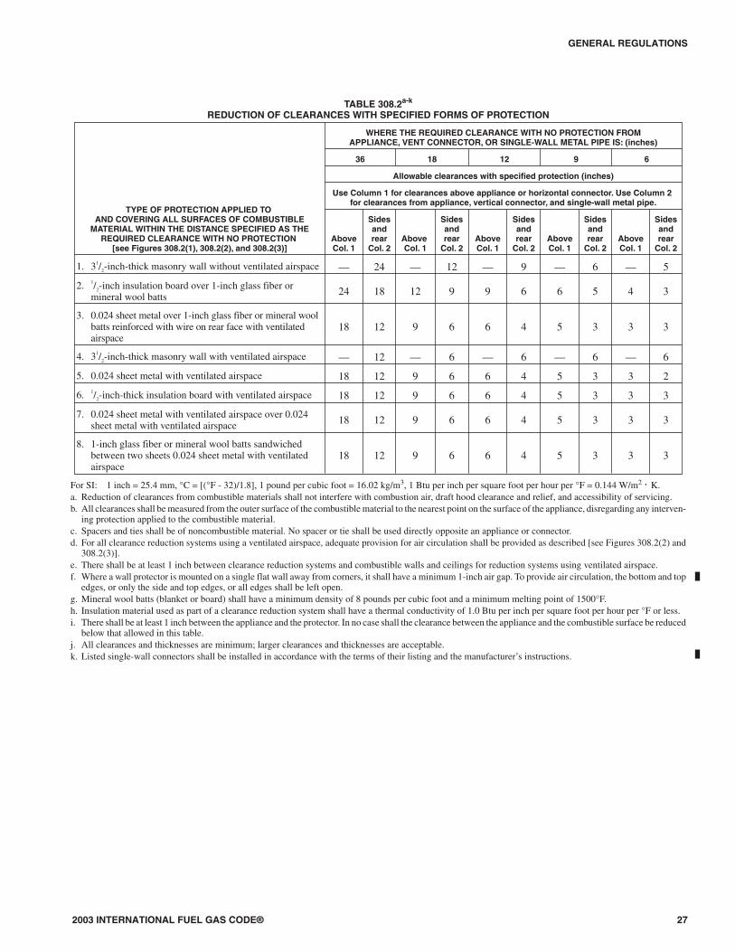
308.2 Reduction table. The allowable clearance reductionshall be based on one of the methods specified in Table 308.2 orshall utilize an assembly listed for such application. Where re-quired clearances are not listed in Table 308.2, the reducedclearances shall be determined by linear interpolation betweenthe distances listed in the table. Reduced clearances shall not bederived by extrapolation below the range of the table. The re-duction of the required clearances to combustibles for listedand labeled appliances and equipment shall be in accordancewith the requirements of this section except that such clear-ances shall not be reduced where reduction is specifically pro-hibited by the terms of the appliance or equipment listing [seeFigures 308.2(1) through 308.2(3)].
308.3 Clearances for indoor air-conditioning equipment.Clearance requirements for indoor air-conditioning equipmentshall comply with Sections 308.3.1 through 308.3.5.
308.3.1 Equipment installed in rooms that are large incomparison with the size of the equipment. Air-condi-tioning equipment installed in rooms that are large in com-parison with the size of the equipment shall be installed withclearances in accordance with the terms of their listing andthe manufacturer’s instructions.
308.3.2 Equipment installed in rooms that are not largein comparison with the size of the equipment. Air-condi-tioning equipment installed in rooms that are not large incomparison with the size of the equipment, such as alcovesand closets, shall be listed for such installations and in-stalled in accordance with the manufacturer’s instructions.Listed clearances shall not be reduced by the protectionmethods described in Table 308.2, regardless of whether theenclosure is of combustible or noncombustible material.
308.3.3 Clearance reduction. Air-conditioning equipmentinstalled in rooms that are large in comparison with the sizeof the equipment shall be permitted to be installed with re-duced clearances to combustible material provided the com-bustible material or equipment is protected as described inTable 308.2.
308.3.4 Plenum clearances. Where the furnace plenum isadjacent to plaster on metal lath or noncombustible materialattached to combustible material, the clearance shall bemeasured to the surface of the plaster or othernoncombustible finish where the clearance specified is 2inches (51 mm) or less.
308.3.5 Clearance from supply ducts. Air-conditioningequipment shall have the clearance from supply ductswithin 3 feet (914 mm) of the furnace plenum be not lessthan that specified from the furnace plenum. No clearance isnecessary beyond this distance.
GENERAL REGULATIONS
26 2003 INTERNATIONAL FUEL GAS CODE®
2003 INTERNATIONAL FUEL GAS CODE® 27
GENERAL REGULATIONS
TABLE 308.2a-k
REDUCTION OF CLEARANCES WITH SPECIFIED FORMS OF PROTECTION
TYPE OF PROTECTION APPLIED TOAND COVERING ALL SURFACES OF COMBUSTIBLE
MATERIAL WITHIN THE DISTANCE SPECIFIED AS THEREQUIRED CLEARANCE WITH NO PROTECTION
[see Figures 308.2(1), 308.2(2), and 308.2(3)]
WHERE THE REQUIRED CLEARANCE WITH NO PROTECTION FROMAPPLIANCE, VENT CONNECTOR, OR SINGLE-WALL METAL PIPE IS: (inches)
36 18 12 9 6
Allowable clearances with specified protection (inches)
Use Column 1 for clearances above appliance or horizontal connector. Use Column 2for clearances from appliance, vertical connector, and single-wall metal pipe.
AboveCol. 1
Sidesandrear
Col. 2AboveCol. 1
Sidesandrear
Col. 2AboveCol. 1
Sidesandrear
Col. 2AboveCol. 1
Sidesandrear
Col. 2AboveCol. 1
Sidesandrear
Col. 2
1. 31/2-inch-thick masonry wall without ventilated airspace — 24 — 12 — 9 — 6 — 5
2. 1/2-inch insulation board over 1-inch glass fiber ormineral wool batts 24 18 12 9 9 6 6 5 4 3
3. 0.024 sheet metal over 1-inch glass fiber or mineral woolbatts reinforced with wire on rear face with ventilatedairspace
18 12 9 6 6 4 5 3 3 3
4. 31/2-inch-thick masonry wall with ventilated airspace — 12 — 6 — 6 — 6 — 6
5. 0.024 sheet metal with ventilated airspace 18 12 9 6 6 4 5 3 3 2
6. 1/2-inch-thick insulation board with ventilated airspace 18 12 9 6 6 4 5 3 3 3
7. 0.024 sheet metal with ventilated airspace over 0.024sheet metal with ventilated airspace 18 12 9 6 6 4 5 3 3 3
8. 1-inch glass fiber or mineral wool batts sandwichedbetween two sheets 0.024 sheet metal with ventilatedairspace
18 12 9 6 6 4 5 3 3 3
For SI: 1 inch = 25.4 mm, °C = [(°F - 32)/1.8], 1 pound per cubic foot = 16.02 kg/m3, 1 Btu per inch per square foot per hour per °F = 0.144 W/m2 ⋅ K.a. Reduction of clearances from combustible materials shall not interfere with combustion air, draft hood clearance and relief, and accessibility of servicing.b. All clearances shall be measured from the outer surface of the combustible material to the nearest point on the surface of the appliance, disregarding any interven-
ing protection applied to the combustible material.c. Spacers and ties shall be of noncombustible material. No spacer or tie shall be used directly opposite an appliance or connector.d. For all clearance reduction systems using a ventilated airspace, adequate provision for air circulation shall be provided as described [see Figures 308.2(2) and
308.2(3)].e. There shall be at least 1 inch between clearance reduction systems and combustible walls and ceilings for reduction systems using ventilated airspace.f. Where a wall protector is mounted on a single flat wall away from corners, it shall have a minimum 1-inch air gap. To provide air circulation, the bottom and top
edges, or only the side and top edges, or all edges shall be left open.g. Mineral wool batts (blanket or board) shall have a minimum density of 8 pounds per cubic foot and a minimum melting point of 1500°F.h. Insulation material used as part of a clearance reduction system shall have a thermal conductivity of 1.0 Btu per inch per square foot per hour per °F or less.i. There shall be at least 1 inch between the appliance and the protector. In no case shall the clearance between the appliance and the combustible surface be reduced
below that allowed in this table.j. All clearances and thicknesses are minimum; larger clearances and thicknesses are acceptable.k. Listed single-wall connectors shall be installed in accordance with the terms of their listing and the manufacturer’s instructions.
308.4 Central-heating boilers and furnaces. Clearance re-quirements for central-heating boilers and furnaces shall com-ply with Sections 308.4.1 through 308.4.6. The clearance tothis equipment shall not interfere with combustion air, drafthood clearance and relief, and accessibility for servicing.
308.4.1 Equipment installed in rooms that are large incomparison with the size of the equipment. Central-heat-ing furnaces and low-pressure boilers installed in roomslarge in comparison with the size of the equipment shall beinstalled with clearances in accordance with the terms oftheir listing and the manufacturer’s instructions.
GENERAL REGULATIONS
28 2003 INTERNATIONAL FUEL GAS CODE®
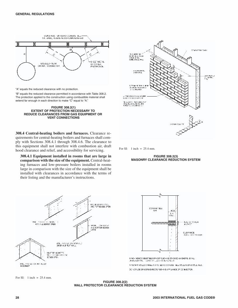
For SI: 1 inch = 25.4 mm.FIGURE 308.2(2)
WALL PROTECTOR CLEARANCE REDUCTION SYSTEM
For SI: 1 inch = 25.4 mm.
FIGURE 308.2(3)MASONRY CLEARANCE REDUCTION SYSTEM
“A” equals the reduced clearance with no protection.
“B” equals the reduced clearance permitted in accordance with Table 308.2.The protection applied to the construction using combustible material shallextend far enough in each direction to make “C” equal to “A.”
FIGURE 308.2(1)EXTENT OF PROTECTION NECESSARY TO
REDUCE CLEARANCES FROM GAS EQUIPMENT ORVENT CONNECTIONS

308.4.2 Equipment installed in rooms that are not large incomparison with the size of the equipment. Central-heat-ing furnaces and low-pressure boilers installed in rooms thatare not large in comparison with the size of the equipment,such as alcoves and closets, shall be listed for such installa-tions. Listed clearances shall not be reduced by the protectionmethods described in Table 308.2 and illustrated in Figures308.2(1) through 308.2(3), regardless of whether the enclo-sure is of combustible or noncombustible material.
308.4.3 Clearance reduction. Central-heating furnacesand low-pressure boilers installed in rooms that are large incomparison with the size of the equipment shall be permit-ted to be installed with reduced clearances to combustiblematerial provided the combustible material or equipment isprotected as described in Table 308.2.
308.4.4 Clearance for servicing equipment. Front clear-ance shall be sufficient for servicing the burner and the fur-nace or boiler.
308.4.5 Plenum clearances. Where the furnace plenum isadjacent to plaster on metal lath or noncombustible materialattached to combustible material, the clearance shall bemeasured to the surface of the plaster or othernoncombustible finish where the clearance specified is 2inches (51 mm) or less.
308.4.6 Clearance from supply ducts. Central-heating fur-naces shall have the clearance from supply ducts within 3feet (914 mm) of the furnace plenum be not less than thatspecified from the furnace plenum. No clearance is neces-sary beyond this distance.
SECTION 309 (IFGC)ELECTRICAL
309.1 Grounding. Gas piping shall not be used as a groundingelectrode.
309.2 Connections. Electrical connections between equip-ment and the building wiring, including the grounding of theequipment, shall conform to the ICC Electrical Code.
SECTION 310 (IFGS)ELECTRICAL BONDING
310.1 Gas pipe bonding. Each above-ground portion of a gaspiping system that is likely to become energized shall be elec-trically continuous and bonded to an effective ground-fault cur-rent path. Gas piping shall be considered to be bonded where itis connected to gas utilization equipment that is connected tothe equipment grounding conductor of the circuit supplyingthat equipment.
2003 INTERNATIONAL FUEL GAS CODE® 29
GENERAL REGULATIONS

30 2003 INTERNATIONAL FUEL GAS CODE®

CHAPTER 4
GAS PIPING INSTALLATIONS
SECTION 401 (IFGC)GENERAL
401.1 Scope. This chapter shall govern the design, installation,modification and maintenance of piping systems. The applica-bility of this code to piping systems extends from the point ofdelivery to the connections with the equipment and includes thedesign, materials, components, fabrication, assembly, installa-tion, testing, inspection, operation and maintenance of suchpiping systems.
401.1.1 Utility piping systems located within buildings.Utility service piping located within buildings shall be in-stalled in accordance with the structural safety and fire pro-tection provisions of the International Building Code.
401.2 Liquefied petroleum gas storage. The storage systemfor liquefied petroleum gas shall be designed and installed inaccordance with the International Fire Code and NFPA 58.
401.3 Modifications to existing systems. In modifying or add-ing to existing piping systems, sizes shall be maintained in ac-cordance with this chapter.
401.4 Additional appliances. Where an additional applianceis to be served, the existing piping shall be checked to deter-mine if it has adequate capacity for all appliances served. If in-adequate, the existing system shall be enlarged as required orseparate piping of adequate capacity shall be provided.
401.5 Identification. For other than black steel pipe, exposedpiping shall be identified by a yellow label marked “Gas” inblack letters. The marking shall be spaced at intervals not ex-ceeding 5 feet (1524 mm). The marking shall not be required onpipe located in the same room as the equipment served.
401.6 Interconnections. Where two or more meters are in-stalled on the same premises but supply separate consumers,the piping systems shall not be interconnected on the outlet sideof the meters.
401.7 Piping meter identification. Piping from multiple me-ter installations shall be marked with an approved permanentidentification by the installer so that the piping system suppliedby each meter is readily identifiable.
401.8 Minimum sizes. All pipe utilized for the installation, ex-tension and alteration of any piping system shall be sized tosupply the full number of outlets for the intended purpose andshall be sized in accordance with Section 402.
SECTION 402 (IFGS)PIPE SIZING
402.1 General considerations. Piping systems shall be of suchsize and so installed as to provide a supply of gas sufficient tomeet the maximum demand without undue loss of pressure be-tween the point of delivery and the gas utilization equipment.
402.2 Maximum gas demand. The volume of gas to be pro-vided, in cubic feet per hour, shall be determined directly fromthe manufacturer’s input ratings of the gas utilization equip-ment served. Where an input rating is not indicated, the gassupplier, equipment manufacturer or a qualified agency shallbe contacted, or the rating from Table 402.2 shall be used forestimating the volume of gas to be supplied.
The total connected hourly load shall be used as the basis forpipe sizing, assuming that all equipment could be operating at fullcapacity simultaneously. Where a diversity of load can be estab-lished, pipe sizing shall be permitted to be based on such loads.
TABLE 402.2APPROXIMATE GAS INPUT FOR TYPICAL APPLIANCES
APPLIANCEINPUT BTU/H
(Approx.)
Space Heating Units
Hydronic boiler
Single family 100,000
Multifamily, per unit 60,000
Warm-air furnace
Single family 100,000
Multifamily, per unit 60,000
Space and Water Heating Units
Hydronic boiler
Single family 120,000
Multifamily, per unit 75,000
Water Heating Appliances
Water heater, automatic instantaneous 35,000
Capacity at 2 gal./minute 50,000
Capacity at 4 gal./minute
Capacity at 6 gal./minute 142,800
Water heater, automatic storage, 30- to 40-gal. tank 285,000
Water heater, automatic storage, 50-gal. tank 428,400
Water heater, domestic, circulating or side-arm 35,000
Cooking Appliances
Built-in oven or broiler unit, domestic 65,000
Built-in top unit, domestic 25,000
Range, free-standing, domestic 40,000
Other Appliances
Barbecue 3,000
Clothes dryer, Type 1 (domestic) 35,000
Gas fireplace, direct vent 40,000
Gas light 80,000
Gas log 40,000
Refrigerator 2,500
For SI: 1 British thermal unit per hour = 0.293 W, 1 gallon = 3.785 L,1 gallon per minute = 3.785 L/m.
2003 INTERNATIONAL FUEL GAS CODE® 31
402.3 Sizing. Gas piping shall be sized in accordance with oneof the following:
1. Pipe sizing tables or sizing equations in accordance withSection 402.4.
2. The sizing tables included in a listed piping system’smanufacturer’s installation instructions.
3. Other approved engineering methods.
402.4 Sizing tables and equations. Where Tables 402.4(1)through 402.4(33) are used to size piping or tubing, the pipelength shall be determined in accordance with Section 402.4.1,402.4.2 or 402.4.3.
Where Equations 4-1 and 4-2 are used to size piping or tub-ing, the pipe or tubing shall have smooth inside walls and thepipe length shall be determined in accordance with Section402.4.1, 402.4.2 or 402.4.3.
1. Low-pressure gas equation [Less than 1.5 pounds persquare inch (psi) (10.3 kPa)]:
DQ
H
C Lr
=
×
0 381
0 206
1917
.
.
.∆
(Equation 4-1)
2. High-pressure gas equation [1.5 psi (10.3 kPa) andabove]:
( )D
Q
P P Y
C Lr
=− ×
×
0 381
12
22
0 206
18 93
.
.
.
(Equation 4-2)
where:
D = Inside diameter of pipe, inches (mm).
Q = Input rate appliance(s), cubic feet per hour at 60°F(16°C) and 30-inch mercury column
P1 = Upstream pressure, psia (P1 + 14.7)
P2 = Downstream pressure, psia (P2 + 14.7)
L = Equivalent length of pipe, feet
∆H = Pressure drop, inch water column (27.7 inch water col-umn = 1 psi)
TABLE 402.4Cr AND Y VALUES FOR NATURAL GAS AND
UNDILUTED PROPANE AT STANDARD CONDITIONS
GAS
EQUATION FACTORS
Cr Y
Natural gas 0.6094 0.9992
Undiluted propane 1.2462 0.9910
For SI: 1 cubic foot = 0.028 m3, 1 foot = 305 mm, 1-inch water column =0.249 kPa, 1 pound per square inch = 6.895 kPa, 1 British thermalunit per hour = 0.293 W.
402.4.1 Longest length method. The pipe size of each sec-tion of gas piping shall be determined using the longestlength of piping from the point of delivery to the most re-mote outlet and the load of the section.
402.4.2 Branch length method. Pipe shall be sized as fol-lows:
1. Pipe size of each section of the longest pipe run fromthe point of delivery to the most remote outlet shall bedetermined using the longest run of piping and theload of the section.
2. The pipe size of each section of branch piping not pre-viously sized shall be determined using the length ofpiping from the point of delivery to the most remoteoutlet in each branch and the load of the section.
402.4.3 Hybrid pressure. The pipe size for each section ofhigher pressure gas piping shall be determined using thelongest length of piping from the point of delivery to themost remote line pressure regulator. The pipe size from theline pressure regulator to each outlet shall be determined us-ing the length of piping from the regulator to the most re-mote outlet served by the regulator.
402.5 Allowable pressure drop. The design pressure loss inany piping system under maximum probable flow conditions,from the point of delivery to the inlet connection of the equip-ment, shall be such that the supply pressure at the equipment isgreater than the minimum pressure required for proper equip-ment operation.
402.6 Maximum design operating pressure. The maximumdesign operating pressure for piping systems located insidebuildings shall not exceed 5 pounds per square inch gauge(psig) (34 kPa gauge) except where one or more of the follow-ing conditions are met:
1. The piping system is welded.
2. The piping is located in a ventilated chase or otherwiseenclosed for protection against accidental gas accumula-tion.
3. The piping is located inside buildings or separate areas ofbuildings used exclusively for:
3.1. Industrial processing or heating;
3.2. Research;
3.3. Warehousing; or
3.4. Boiler or mechanical equipment rooms.
4. The piping is a temporary installation for buildings underconstruction.
402.6.1 Liquefied petroleum gas systems. The operatingpressure for undiluted LP-gas systems shall not exceed 20psig (140 kPa gauge). Buildings having systems designed tooperate below -5°F (-21°C) or with butane or a propane-bu-tane mix shall be designed to either accommodate liquidLP-gas or prevent LP-gas vapor from condensing into a liq-uid.
Exception: Buildings or separate areas of buildings con-structed in accordance with Chapter 7 of NFPA 58, andused exclusively to house industrial processes, researchand experimental laboratories, or equipment or process-ing having similar hazards.
GAS PIPING INSTALLATIONS
32 2003 INTERNATIONAL FUEL GAS CODE®

2003 INTERNATIONAL FUEL GAS CODE® 33
GAS PIPING INSTALLATIONS
TABLE 402.4(1)SCHEDULE 40 METALLIC PIPE
Gas Natural
Inlet Pressure 0.50 psi or less
Pressure Drop 0.3 inch WC
Specific Gravity 0.60
PIPE SIZE (in.)
Nominal 1/43/8
1/23/4 1 11/4 11/2 2 21/2 3 4
Actual ID 0.364 0.493 0.622 0.824 1.049 1.380 1.610 2.067 2.469 3.068 4.026
Length (ft) Maximum Capacity in Cubic Feet of Gas per Hour
10 32 72 132 278 520 1,050 1,600 3,050 4,800 8,500 17,500
20 22 49 92 190 350 730 1,100 2,100 3,300 5,900 12,000
30 18 40 73 152 285 590 890 1,650 2,700 4,700 9,700
40 15 34 63 130 245 500 760 1,450 2,300 4,100 8,300
50 14 30 56 115 215 440 670 1,270 2,000 3,600 7,400
60 12 27 50 105 195 400 610 1,150 1,850 3,250 6,800
70 11 25 46 96 180 370 560 1,050 1,700 3,000 6,200
80 11 23 43 90 170 350 530 990 1,600 2,800 5,800
90 10 22 40 84 160 320 490 930 1,500 2,600 5,400
100 9 21 38 79 150 305 460 870 1,400 2,500 5,100
125 8 18 34 72 130 275 410 780 1,250 2,200 4,500
150 8 17 31 64 120 250 380 710 1,130 2,000 4,100
175 7 15 28 59 110 225 350 650 1,050 1,850 3,800
200 6 14 26 55 100 210 320 610 980 1,700 3,500
For SI: 1 inch = 25.4 mm, 1 foot = 304.8 mm, 1 cubic foot per hour = 0.0283 m3/h, 1 pound per square inch = 6.895 kPa, 1-inch water column = 0.2488 kPa.
TABLE 402.4(2)SCHEDULE 40 METALLIC PIPE
Gas Natural
Inlet Pressure 0.50 psi or less
Pressure Drop 0.5 inch WC
Specific Gravity 0.60
PIPE SIZE (in.)
Nominal 1/43/8
1/23/4 1 11/4 11/2 2 21/2 3 4
Actual ID 0.364 0.493 0.622 0.824 1.049 1.380 1.610 2.067 2.469 3.068 4.026
Length (ft) Maximum Capacity in Cubic Feet of Gas per Hour
10 43 95 175 360 680 1,400 2,100 3,950 6,300 11,000 23,000
20 29 65 120 250 465 950 1,460 2,750 4,350 7,700 15,800
30 24 52 97 200 375 770 1,180 2,200 3,520 6,250 12,800
40 20 45 82 170 320 660 990 1,900 3,000 5,300 10,900
50 18 40 73 151 285 580 900 1,680 2,650 4,750 9,700
60 16 36 66 138 260 530 810 1,520 2,400 4,300 8,800
70 15 33 61 125 240 490 750 1,400 2,250 3,900 8,100
80 14 31 57 118 220 460 690 1,300 2,050 3,700 7,500
90 13 29 53 110 205 430 650 1,220 1,950 3,450 7,200
100 12 27 50 103 195 400 620 1,150 1,850 3,250 6,700
125 11 24 44 93 175 360 550 1,020 1,650 2,950 6,000
150 10 22 40 84 160 325 500 950 1,500 2,650 5,500
175 9 20 37 77 145 300 460 850 1,370 2,450 5,000
200 8 19 35 72 135 280 430 800 1,280 2,280 4,600
For SI: 1 inch = 25.4 mm, 1 foot = 304.8 mm, 1 cubic foot per hour = 0.0283 m3/h, 1 pound per square inch = 6.895 kPa, 1-inch water column = 0.2488 kPa.

GAS PIPING INSTALLATIONS
34 2003 INTERNATIONAL FUEL GAS CODE®
TABLE 402.4(3)SCHEDULE 40 METALLIC PIPE
Gas Natural
Inlet Pressure 2.0 psi
Pressure Drop 1.0 psi
Specific Gravity 0.60
PIPE SIZE (in.)
Nominal 1/23/4 1 11/4 11/2 2 21/2 3 4
Actual ID 0.622 0.824 1.049 1.380 1.610 2.067 2.469 3.068 4.026
Length (ft) Maximum Capacity in Cubic Feet of Gas per Hour
10 1,506 3,041 5,561 11,415 17,106 32,944 52,505 92,819 189,326
20 1,065 2,150 3,932 8,072 12,096 23,295 37,127 65,633 133,873
30 869 1,756 3,211 6,591 9,876 19,020 30,314 53,589 109,307
40 753 1,521 2,781 5,708 8,553 16,472 26,253 46,410 94,663
50 673 1,360 2,487 5,105 7,650 14,733 23,481 41,510 84,669
60 615 1,241 2,270 4,660 6,983 13,449 21,435 37,893 77,292
70 569 1,150 2,102 4,315 6,465 12,452 19,845 35,082 71,558
80 532 1,075 1,966 4,036 6,048 11,647 18,563 32,817 66,937
90 502 1,014 1,854 3,805 5,702 10,981 17,502 30,940 63,109
100 462 934 1,708 3,508 5,257 10,125 16,138 28,530 58,194
125 414 836 1,528 3,138 4,702 9,056 14,434 25,518 52,050
150 372 751 1,373 2,817 4,222 8,130 12,960 22,911 46,732
175 344 695 1,271 2,608 3,909 7,527 11,999 21,211 43,265
200 318 642 1,174 2,413 3,613 6,959 11,093 19,608 39,997
For SI: 1 inch = 25.4 mm, 1 foot = 304.8 mm, 1 cubic foot per hour = 0.0283 m3/h, 1 pound per square inch = 6.895 kPa.
TABLE 402.4(4)SCHEDULE 40 METALLIC PIPE
Gas Natural
Inlet Pressure 5.0 psi
Pressure Drop 3.5 psi
Specific Gravity 0.60
PIPE SIZE (in.)
Nominal 1/23/4 1 11/4 11/2 2 21/2 3 4
Actual ID 0.622 0.824 1.049 1.380 1.610 2.067 2.469 3.068 4.026
Length (ft) Maximum Capacity in Cubic Feet of Gas per Hour
10 3,185 6,434 11,766 24,161 36,206 69,727 111,133 196,468 400,732
20 2,252 4,550 8,320 17,084 25,602 49,305 78,583 138,924 283,361
30 1,839 3,715 6,793 13,949 20,904 40,257 64,162 113,431 231,363
40 1,593 3,217 5,883 12,080 18,103 34,864 55,566 98,234 200,366
50 1,425 2,878 5,262 10,805 16,192 31,183 49,700 87,863 179,213
60 1,301 2,627 4,804 9,864 14,781 28,466 45,370 80,208 163,598
70 1,204 2,432 4,447 9,132 13,685 26,354 42,004 74,258 151,463
80 1,153 2,330 4,260 8,542 12,801 24,652 39,291 69,462 141,680
90 1,062 2,145 3,922 8,054 12,069 23,242 37,044 65,489 133,577
100 979 1,978 3,617 7,427 11,128 21,433 34,159 60,387 123,173
125 876 1,769 3,235 6,643 9,953 19,170 30,553 54,012 110,169
150 786 1,589 2,905 5,964 8,937 17,211 27,431 48,494 98,911
175 728 1,471 2,690 5,522 8,274 15,934 25,396 44,897 91,574
200 673 1,360 2,487 5,104 7,649 14,729 23,478 41,504 84,656
For SI: 1 inch = 25.4 mm, 1 foot = 304.8 mm, 1 cubic foot per hour = 0.0283 m3/h, 1 pound per square inch = 6.895 kPa.

2003 INTERNATIONAL FUEL GAS CODE® 35
GAS PIPING INSTALLATIONS
TABLE 402.4(6)SCHEDULE 40 METALLIC PIPE
Gas Natural
Inlet Pressure 1.0 psi or less
Pressure Drop 0.5 inch WC
Specific Gravity 0.60
PIPE SIZE (in.)
Nominal 1 11/4 11/2 2 21/2 3 31/2 4 5 6 8 10 12
Actual ID 1.049 1.380 1.610 2.067 2.469 3.068 3.548 4.026 5.047 6.065 7.981 10.020 11.938
Length (ft) Maximum Capacity in Cubic Feet of Gas per Hour
50 284 583 873 1,681 2,680 4,738 6,937 9,663 17,482 28,308 58,161 105,636 167,236
100 195 400 600 1,156 1,842 3,256 4,767 6,641 12,015 19,456 39,974 72,603 114,940
150 157 322 482 928 1,479 2,615 3,828 5,333 9,649 15,624 32,100 58,303 92,301
200 134 275 412 794 1,266 2,238 3,277 4,565 8,258 13,372 27,474 49,900 78,998
250 119 244 366 704 1,122 1,983 2,904 4,046 7,319 11,851 24,350 44,225 70,014
300 108 221 331 638 1,017 1,797 2,631 3,666 6,632 10,738 22,062 40,071 63,438
400 92 189 283 546 870 1,538 2,252 3,137 5,676 9,190 18,883 34,296 54,295
500 82 168 251 484 771 1,363 1,996 2,780 5,030 8,145 16,735 30,396 48,120
1,000 56 115 173 333 530 937 1,372 1,911 3,457 5,598 11,502 20,891 33,073
1,500 45 93 139 267 426 752 1,102 1,535 2,776 4,496 9,237 16,776 26,559
2,000 39 79 119 229 364 644 943 1,313 2,376 3,848 7,905 14,358 22,731
For SI: 1 inch = 25.4 mm, 1 foot = 304.8 mm, 1 cubic foot per hour = 0.0283 m3/h, 1 pound per square inch = 6.895 kPa, 1-inch water column = 0.2488 kPa.
TABLE 402.4(5)SCHEDULE 40 METALLIC PIPE
Gas Natural
Inlet Pressure 1.0 psi or less
Pressure Drop 0.3 inch WC
Specific Gravity 0.60
PIPE SIZE (in.)
Nominal 1 11/4 11/2 2 21/2 3 31/2 4 5 6 8 10 12
Actual ID 1.049 1.380 1.610 2.067 2.469 3.068 3.548 4.026 5.047 6.065 7.981 10.020 11.938
Length (ft) Maximum Capacity in Cubic Feet of Gas per Hour
50 215 442 662 1,275 2,033 3,594 5,262 7,330 13,261 21,472 44,118 80,130 126,855
100 148 304 455 877 1,397 2,470 3,616 5,038 9,114 14,758 30,322 55,073 87,187
150 119 244 366 704 1,122 1,983 2,904 4,046 7,319 11,851 24,350 44,225 70,014
200 102 209 313 602 960 1,698 2,485 3,462 6,264 10,143 20,840 37,851 59,923
250 90 185 277 534 851 1,505 2,203 3,069 5,552 8,990 18,470 33,547 53,109
300 82 168 251 484 771 1,363 1,996 2,780 5,030 8,145 16,735 30,396 48,120
400 70 143 215 414 660 1,167 1,708 2,380 4,305 6,971 14,323 26,015 41,185
500 62 127 191 367 585 1,034 1,514 2,109 3,816 6,178 12,694 23,056 36,501
1,000 43 87 131 252 402 711 1,041 1,450 2,623 4,246 8,725 15,847 25,087
1,500 34 70 105 203 323 571 836 1,164 2,106 3,410 7,006 12,725 20,146
2,000 29 60 90 173 276 488 715 996 1,802 2,919 5,997 10,891 17,242
For SI: 1 inch = 25.4 mm, 1 foot = 304.8 mm, 1 cubic foot per hour = 0.0283 m3/h, 1 pound per square inch = 6.895 kPa, 1-inch water column = 0.2488 kPa.
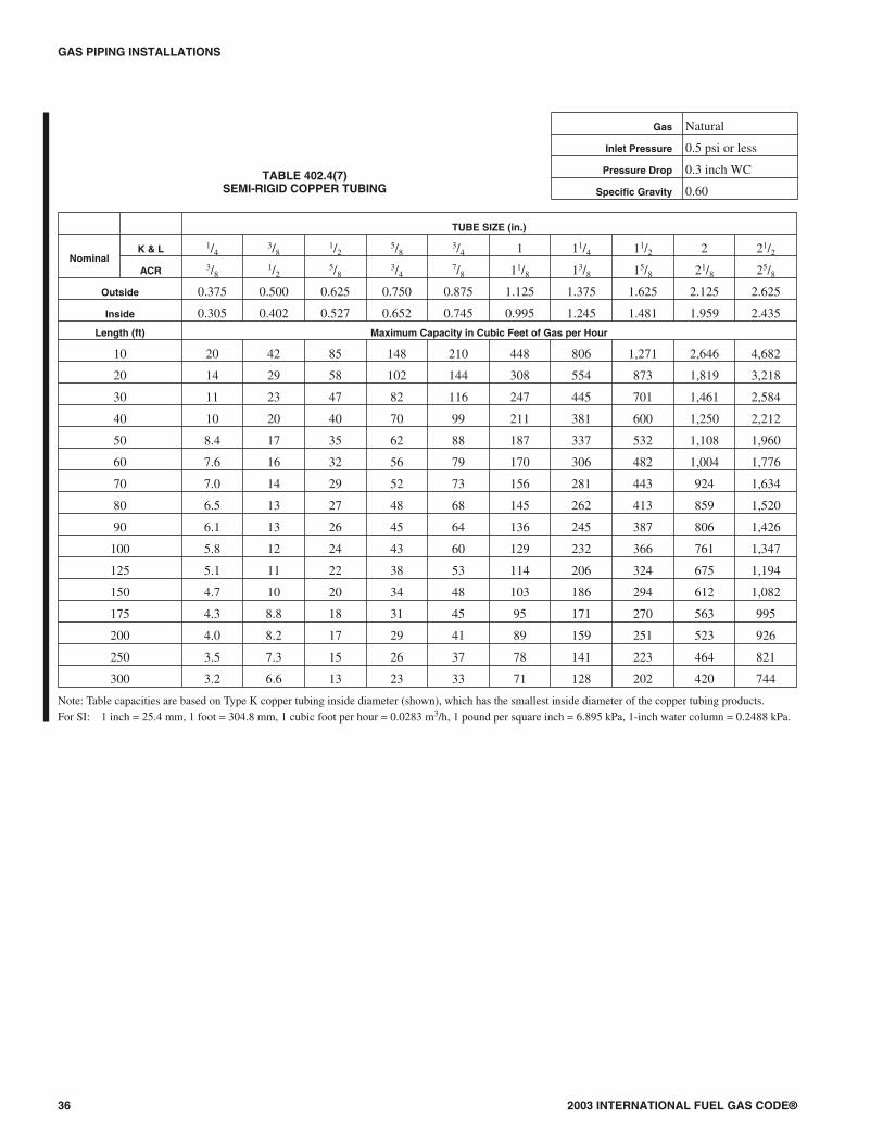
GAS PIPING INSTALLATIONS
36 2003 INTERNATIONAL FUEL GAS CODE®
TABLE 402.4(7)SEMI-RIGID COPPER TUBING
Gas Natural
Inlet Pressure 0.5 psi or less
Pressure Drop 0.3 inch WC
Specific Gravity 0.60
TUBE SIZE (in.)
NominalK & L 1/4
3/81/2
5/83/4 1 11/4 11/2 2 21/2
ACR 3/81/2
5/83/4
7/8 11/8 13/8 15/8 21/8 25/8
Outside 0.375 0.500 0.625 0.750 0.875 1.125 1.375 1.625 2.125 2.625
Inside 0.305 0.402 0.527 0.652 0.745 0.995 1.245 1.481 1.959 2.435
Length (ft) Maximum Capacity in Cubic Feet of Gas per Hour
10 20 42 85 148 210 448 806 1,271 2,646 4,682
20 14 29 58 102 144 308 554 873 1,819 3,218
30 11 23 47 82 116 247 445 701 1,461 2,584
40 10 20 40 70 99 211 381 600 1,250 2,212
50 8.4 17 35 62 88 187 337 532 1,108 1,960
60 7.6 16 32 56 79 170 306 482 1,004 1,776
70 7.0 14 29 52 73 156 281 443 924 1,634
80 6.5 13 27 48 68 145 262 413 859 1,520
90 6.1 13 26 45 64 136 245 387 806 1,426
100 5.8 12 24 43 60 129 232 366 761 1,347
125 5.1 11 22 38 53 114 206 324 675 1,194
150 4.7 10 20 34 48 103 186 294 612 1,082
175 4.3 8.8 18 31 45 95 171 270 563 995
200 4.0 8.2 17 29 41 89 159 251 523 926
250 3.5 7.3 15 26 37 78 141 223 464 821
300 3.2 6.6 13 23 33 71 128 202 420 744
Note: Table capacities are based on Type K copper tubing inside diameter (shown), which has the smallest inside diameter of the copper tubing products.For SI: 1 inch = 25.4 mm, 1 foot = 304.8 mm, 1 cubic foot per hour = 0.0283 m3/h, 1 pound per square inch = 6.895 kPa, 1-inch water column = 0.2488 kPa.
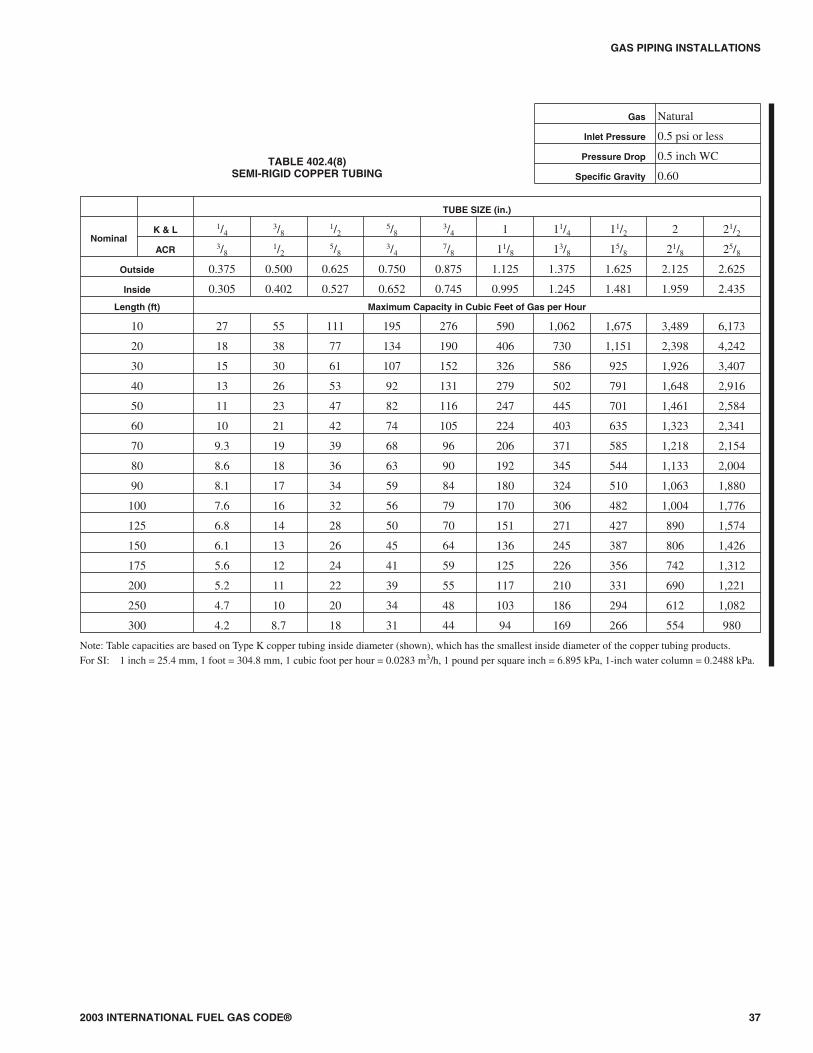
2003 INTERNATIONAL FUEL GAS CODE® 37
GAS PIPING INSTALLATIONS
TABLE 402.4(8)SEMI-RIGID COPPER TUBING
Gas Natural
Inlet Pressure 0.5 psi or less
Pressure Drop 0.5 inch WC
Specific Gravity 0.60
TUBE SIZE (in.)
NominalK & L 1/4
3/81/2
5/83/4 1 11/4 11/2 2 21/2
ACR 3/81/2
5/83/4
7/8 11/8 13/8 15/8 21/8 25/8
Outside 0.375 0.500 0.625 0.750 0.875 1.125 1.375 1.625 2.125 2.625
Inside 0.305 0.402 0.527 0.652 0.745 0.995 1.245 1.481 1.959 2.435
Length (ft) Maximum Capacity in Cubic Feet of Gas per Hour
10 27 55 111 195 276 590 1,062 1,675 3,489 6,173
20 18 38 77 134 190 406 730 1,151 2,398 4,242
30 15 30 61 107 152 326 586 925 1,926 3,407
40 13 26 53 92 131 279 502 791 1,648 2,916
50 11 23 47 82 116 247 445 701 1,461 2,584
60 10 21 42 74 105 224 403 635 1,323 2,341
70 9.3 19 39 68 96 206 371 585 1,218 2,154
80 8.6 18 36 63 90 192 345 544 1,133 2,004
90 8.1 17 34 59 84 180 324 510 1,063 1,880
100 7.6 16 32 56 79 170 306 482 1,004 1,776
125 6.8 14 28 50 70 151 271 427 890 1,574
150 6.1 13 26 45 64 136 245 387 806 1,426
175 5.6 12 24 41 59 125 226 356 742 1,312
200 5.2 11 22 39 55 117 210 331 690 1,221
250 4.7 10 20 34 48 103 186 294 612 1,082
300 4.2 8.7 18 31 44 94 169 266 554 980
Note: Table capacities are based on Type K copper tubing inside diameter (shown), which has the smallest inside diameter of the copper tubing products.For SI: 1 inch = 25.4 mm, 1 foot = 304.8 mm, 1 cubic foot per hour = 0.0283 m3/h, 1 pound per square inch = 6.895 kPa, 1-inch water column = 0.2488 kPa.
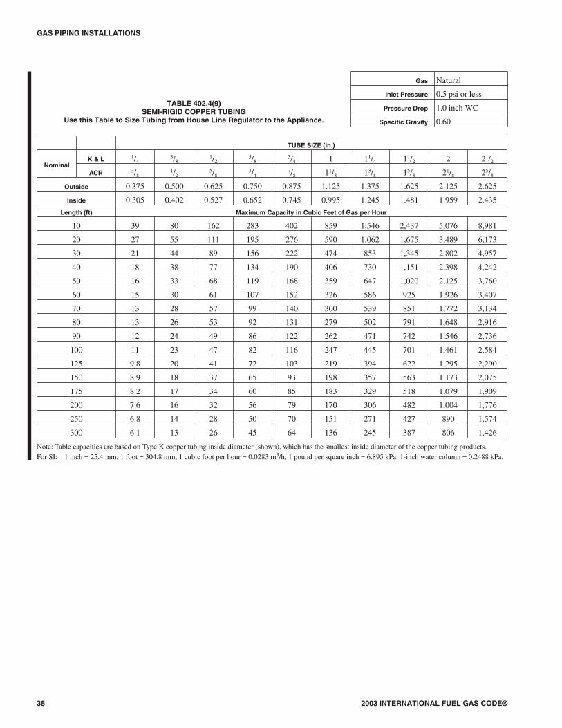
GAS PIPING INSTALLATIONS
38 2003 INTERNATIONAL FUEL GAS CODE®
TABLE 402.4(9)SEMI-RIGID COPPER TUBING
Use this Table to Size Tubing from House Line Regulator to the Appliance.
Gas Natural
Inlet Pressure 0.5 psi or less
Pressure Drop 1.0 inch WC
Specific Gravity 0.60
TUBE SIZE (in.)
NominalK & L 1/4
3/81/2
5/83/4 1 11/4 11/2 2 21/2
ACR 3/81/2
5/83/4
7/8 11/8 13/8 15/8 21/8 25/8
Outside 0.375 0.500 0.625 0.750 0.875 1.125 1.375 1.625 2.125 2.625
Inside 0.305 0.402 0.527 0.652 0.745 0.995 1.245 1.481 1.959 2.435
Length (ft) Maximum Capacity in Cubic Feet of Gas per Hour
10 39 80 162 283 402 859 1,546 2,437 5,076 8,981
20 27 55 111 195 276 590 1,062 1,675 3,489 6,173
30 21 44 89 156 222 474 853 1,345 2,802 4,957
40 18 38 77 134 190 406 730 1,151 2,398 4,242
50 16 33 68 119 168 359 647 1,020 2,125 3,760
60 15 30 61 107 152 326 586 925 1,926 3,407
70 13 28 57 99 140 300 539 851 1,772 3,134
80 13 26 53 92 131 279 502 791 1,648 2,916
90 12 24 49 86 122 262 471 742 1,546 2,736
100 11 23 47 82 116 247 445 701 1,461 2,584
125 9.8 20 41 72 103 219 394 622 1,295 2,290
150 8.9 18 37 65 93 198 357 563 1,173 2,075
175 8.2 17 34 60 85 183 329 518 1,079 1,909
200 7.6 16 32 56 79 170 306 482 1,004 1,776
250 6.8 14 28 50 70 151 271 427 890 1,574
300 6.1 13 26 45 64 136 245 387 806 1,426
Note: Table capacities are based on Type K copper tubing inside diameter (shown), which has the smallest inside diameter of the copper tubing products.For SI: 1 inch = 25.4 mm, 1 foot = 304.8 mm, 1 cubic foot per hour = 0.0283 m3/h, 1 pound per square inch = 6.895 kPa, 1-inch water column = 0.2488 kPa.
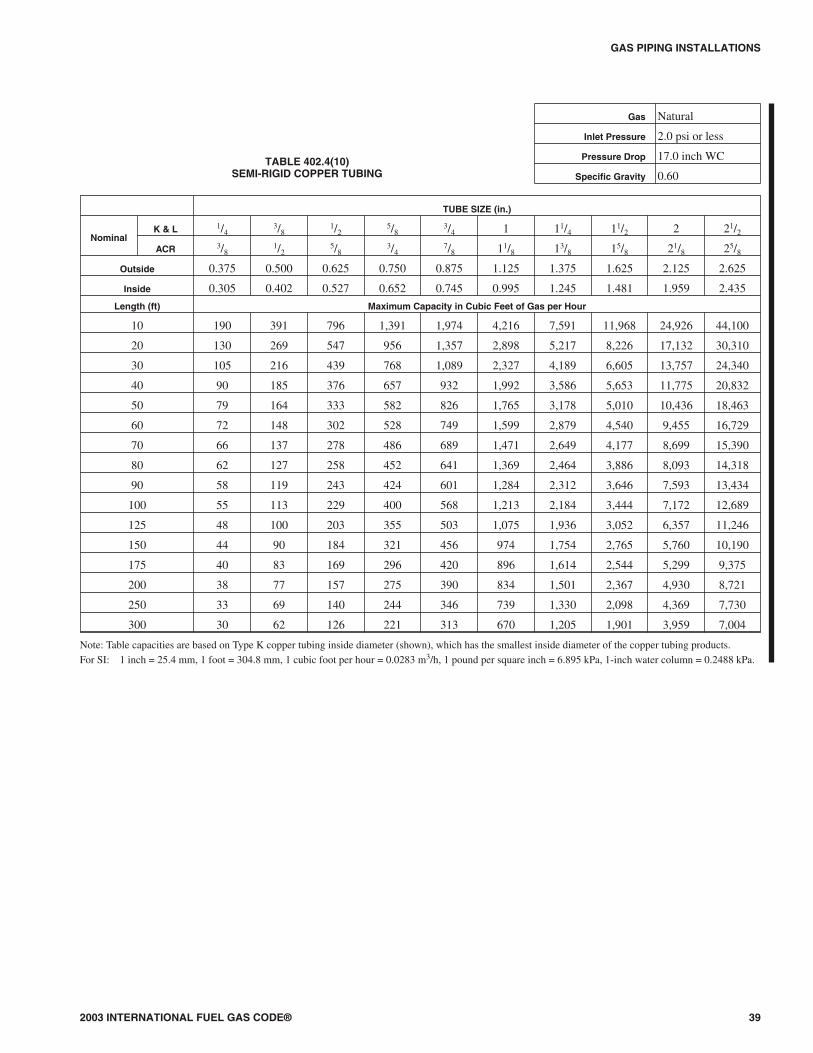
2003 INTERNATIONAL FUEL GAS CODE® 39
GAS PIPING INSTALLATIONS
TABLE 402.4(10)SEMI-RIGID COPPER TUBING
Gas Natural
Inlet Pressure 2.0 psi or less
Pressure Drop 17.0 inch WC
Specific Gravity 0.60
TUBE SIZE (in.)
NominalK & L 1/4
3/81/2
5/83/4 1 11/4 11/2 2 21/2
ACR 3/81/2
5/83/4
7/8 11/8 13/8 15/8 21/8 25/8
Outside 0.375 0.500 0.625 0.750 0.875 1.125 1.375 1.625 2.125 2.625
Inside 0.305 0.402 0.527 0.652 0.745 0.995 1.245 1.481 1.959 2.435
Length (ft) Maximum Capacity in Cubic Feet of Gas per Hour
10 190 391 796 1,391 1,974 4,216 7,591 11,968 24,926 44,100
20 130 269 547 956 1,357 2,898 5,217 8,226 17,132 30,310
30 105 216 439 768 1,089 2,327 4,189 6,605 13,757 24,340
40 90 185 376 657 932 1,992 3,586 5,653 11,775 20,832
50 79 164 333 582 826 1,765 3,178 5,010 10,436 18,463
60 72 148 302 528 749 1,599 2,879 4,540 9,455 16,729
70 66 137 278 486 689 1,471 2,649 4,177 8,699 15,390
80 62 127 258 452 641 1,369 2,464 3,886 8,093 14,318
90 58 119 243 424 601 1,284 2,312 3,646 7,593 13,434
100 55 113 229 400 568 1,213 2,184 3,444 7,172 12,689
125 48 100 203 355 503 1,075 1,936 3,052 6,357 11,246
150 44 90 184 321 456 974 1,754 2,765 5,760 10,190
175 40 83 169 296 420 896 1,614 2,544 5,299 9,375
200 38 77 157 275 390 834 1,501 2,367 4,930 8,721
250 33 69 140 244 346 739 1,330 2,098 4,369 7,730
300 30 62 126 221 313 670 1,205 1,901 3,959 7,004
Note: Table capacities are based on Type K copper tubing inside diameter (shown), which has the smallest inside diameter of the copper tubing products.For SI: 1 inch = 25.4 mm, 1 foot = 304.8 mm, 1 cubic foot per hour = 0.0283 m3/h, 1 pound per square inch = 6.895 kPa, 1-inch water column = 0.2488 kPa.
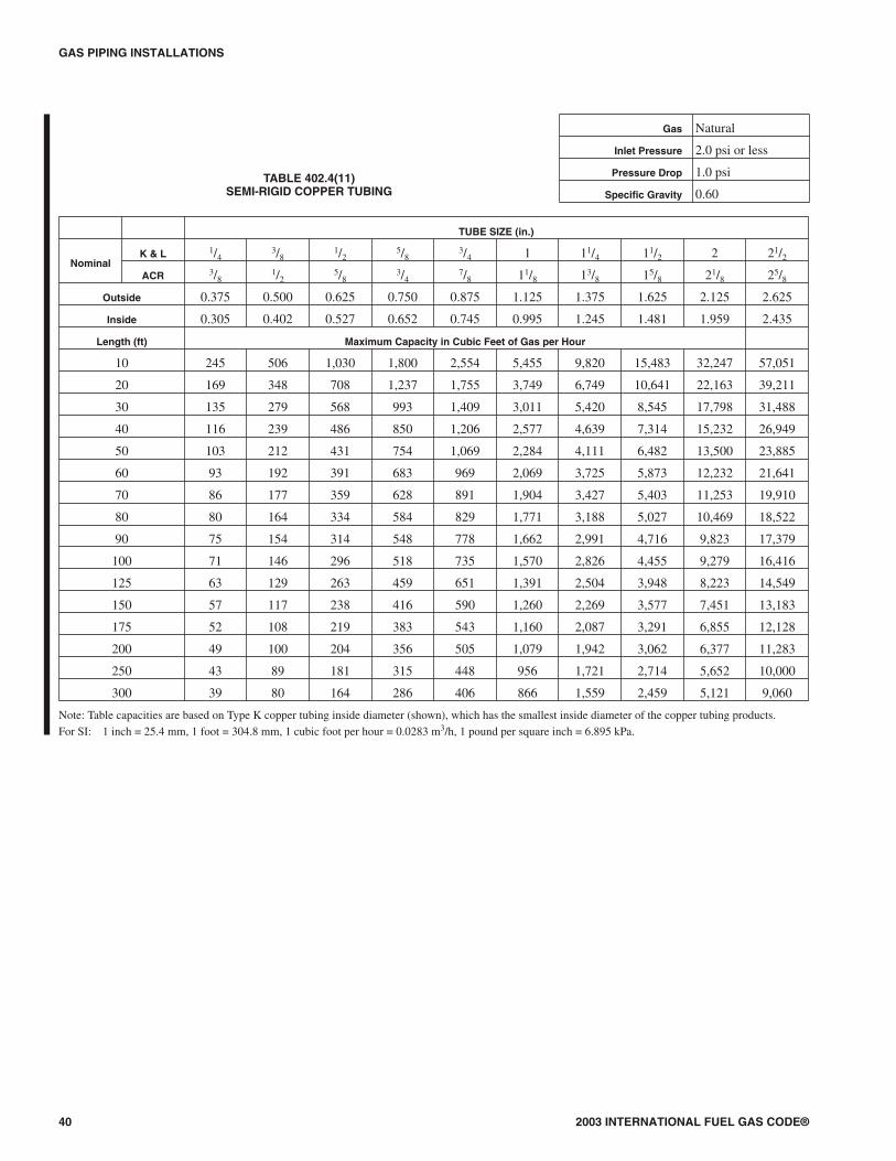
GAS PIPING INSTALLATIONS
40 2003 INTERNATIONAL FUEL GAS CODE®
TUBE SIZE (in.)
NominalK & L 1/4
3/81/2
5/83/4 1 11/4 11/2 2 21/2
ACR 3/81/2
5/83/4
7/8 11/8 13/8 15/8 21/8 25/8
Outside 0.375 0.500 0.625 0.750 0.875 1.125 1.375 1.625 2.125 2.625
Inside 0.305 0.402 0.527 0.652 0.745 0.995 1.245 1.481 1.959 2.435
Length (ft) Maximum Capacity in Cubic Feet of Gas per Hour
10 245 506 1,030 1,800 2,554 5,455 9,820 15,483 32,247 57,051
20 169 348 708 1,237 1,755 3,749 6,749 10,641 22,163 39,211
30 135 279 568 993 1,409 3,011 5,420 8,545 17,798 31,488
40 116 239 486 850 1,206 2,577 4,639 7,314 15,232 26,949
50 103 212 431 754 1,069 2,284 4,111 6,482 13,500 23,885
60 93 192 391 683 969 2,069 3,725 5,873 12,232 21,641
70 86 177 359 628 891 1,904 3,427 5,403 11,253 19,910
80 80 164 334 584 829 1,771 3,188 5,027 10,469 18,522
90 75 154 314 548 778 1,662 2,991 4,716 9,823 17,379
100 71 146 296 518 735 1,570 2,826 4,455 9,279 16,416
125 63 129 263 459 651 1,391 2,504 3,948 8,223 14,549
150 57 117 238 416 590 1,260 2,269 3,577 7,451 13,183
175 52 108 219 383 543 1,160 2,087 3,291 6,855 12,128
200 49 100 204 356 505 1,079 1,942 3,062 6,377 11,283
250 43 89 181 315 448 956 1,721 2,714 5,652 10,000
300 39 80 164 286 406 866 1,559 2,459 5,121 9,060
Note: Table capacities are based on Type K copper tubing inside diameter (shown), which has the smallest inside diameter of the copper tubing products.For SI: 1 inch = 25.4 mm, 1 foot = 304.8 mm, 1 cubic foot per hour = 0.0283 m3/h, 1 pound per square inch = 6.895 kPa.
TABLE 402.4(11)SEMI-RIGID COPPER TUBING
Gas Natural
Inlet Pressure 2.0 psi or less
Pressure Drop 1.0 psi
Specific Gravity 0.60
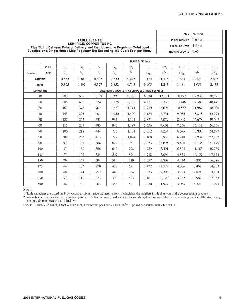
2003 INTERNATIONAL FUEL GAS CODE® 41
GAS PIPING INSTALLATIONS
TABLE 402.4(12)SEMI-RIGID COPPER TUBING
Pipe Sizing Between Point of Delivery and the House Line Regulator. Total LoadSupplied by a Single House Line Regulator Not Exceeding 150 Cubic Feet per Hour.2
Gas Natural
Inlet Pressure 2.0 psi
Pressure Drop 1.5 psi
Specific Gravity 0.60
TUBE SIZE (in.)
Nominal
K & L 1/43/8
1/25/8
3/4 1 11/4 11/2 2 21/2
ACR 3/81/2
5/83/4
7/8 11/8 13/8 15/8 21/8 25/8
Outside 0.375 0.500 0.625 0.750 0.875 1.125 1.375 1.625 2.125 2.625
Inside1 0.305 0.402 0.527 0.652 0.745 0.995 1.245 1.481 1.959 2.435
Length (ft) Maximum Capacity in Cubic Feet of Gas per Hour
10 303 625 1,272 2,224 3,155 6,739 12,131 19,127 39,837 70,481
20 208 430 874 1,528 2,168 4,631 8,338 13,146 27,380 48,441
30 167 345 702 1,227 1,741 3,719 6,696 10,557 21,987 38,900
40 143 295 601 1,050 1,490 3,183 5,731 9,035 18,818 33,293
50 127 262 533 931 1,321 2,821 5,079 8,008 16,678 29,507
60 115 237 483 843 1,197 2,556 4,602 7,256 15,112 26,736
70 106 218 444 776 1,101 2,352 4,234 6,675 13,903 24,597
80 98 203 413 722 1,024 2,188 3,939 6,210 12,934 22,882
90 92 191 388 677 961 2,053 3,695 5,826 12,135 21,470
100 87 180 366 640 908 1,939 3,491 5,504 11,463 20,280
125 77 159 324 567 804 1,718 3,094 4,878 10,159 17,974
150 70 145 294 514 729 1,557 2,803 4,420 9,205 16,286
175 64 133 270 473 671 1,432 2,579 4,066 8,469 14,983
200 60 124 252 440 624 1,333 2,399 3,783 7,878 13,938
250 53 110 223 390 553 1,181 2,126 3,352 6,982 12,353
300 48 99 202 353 501 1,070 1,927 3,038 6,327 11,193
Notes:1. Table capacities are based on Type K copper tubing inside diameter (shown), which has the smallest inside diameter of the copper tubing products.2. When this table is used to size the tubing upstream of a line pressure regulator, the pipe or tubing downstream of the line pressure regulator shall be sized using a
pressure drop no greater than 1 inch w.c.For SI: 1 inch = 25.4 mm, 1 foot = 304.8 mm, 1 cubic foot per hour = 0.0283 m3/h, 1 pound per square inch = 6.895 kPa.

GAS PIPING INSTALLATIONS
42 2003 INTERNATIONAL FUEL GAS CODE®
TUBE SIZE (in.)
NominalK & L 1/4
3/81/2
5/83/4 1 11/4 11/2 2 21/2
ACR 3/81/2
5/83/4
7/8 11/8 13/8 15/8 21/8 25/8
Outside 0.375 0.500 0.625 0.750 0.875 1.125 1.375 1.625 2.125 2.625
Inside 0.305 0.402 0.527 0.652 0.745 0.995 1.245 1.481 1.959 2.435
Length (ft) Maximum Capacity in Cubic Feet of Gas per Hour
10 511 1,054 2,144 3,747 5,315 11,354 20,441 32,229 67,125 118,758
20 351 724 1,473 2,575 3,653 7,804 14,049 22,151 46,135 81,622
30 282 582 1,183 2,068 2,934 6,267 11,282 17,788 37,048 65,545
40 241 498 1,013 1,770 2,511 5,364 9,656 15,224 31,708 56,098
50 214 441 898 1,569 2,225 4,754 8,558 13,493 28,102 49,719
60 194 400 813 1,421 2,016 4,307 7,754 12,225 25,463 45,049
70 178 368 748 1,308 1,855 3,962 7,134 11,247 23,425 41,444
80 166 342 696 1,216 1,726 3,686 6,636 10,463 21,793 38,556
90 156 321 653 1,141 1,619 3,459 6,227 9,817 20,447 36,176
100 147 303 617 1,078 1,529 3,267 5,882 9,273 19,315 34,172
125 130 269 547 955 1,356 2,896 5,213 8,219 17,118 30,286
150 118 243 495 866 1,228 2,624 4,723 7,447 15,510 27,441
175 109 224 456 796 1,130 2,414 4,345 6,851 14,269 25,245
200 101 208 424 741 1,051 2,245 4,042 6,374 13,275 23,486
250 90 185 376 657 932 1,990 3,583 5,649 11,765 20,815
300 81 167 340 595 844 1,803 3,246 5,118 10,660 18,860
Note: Table capacities are based on Type K copper tubing inside diameter (shown), which has the smallest inside diameter of the copper tubing products.For SI: 1 inch = 25.4 mm, 1 foot = 304.8 mm, 1 cubic foot per hour = 0.0283 m3/h, 1 pound per square inch = 6.895 kPa.
TABLE 402.4(13)SEMI-RIGID COPPER TUBING
Gas Natural
Inlet Pressure 5.0 psi or less
Pressure Drop 3.5 psi
Specific Gravity 0.60

2003 INTERNATIONAL FUEL GAS CODE® 43
GAS PIPING INSTALLATIONS
TUBE SIZE (EHD*)
FlowDesignation 13 15 18 19 23 25 30 31 37 46 62
Length (ft) Maximum Capacity in Cubic Feet of Gas per Hour
5 46 63 115 134 225 270 471 546 895 1,790 4,142
10 32 44 82 95 161 192 330 383 639 1,261 2,934
15 25 35 66 77 132 157 267 310 524 1,027 2,398
20 22 31 58 67 116 137 231 269 456 888 2,078
25 19 27 52 60 104 122 206 240 409 793 1,860
30 18 25 47 55 96 112 188 218 374 723 1,698
40 15 21 41 47 83 97 162 188 325 625 1,472
50 13 19 37 42 75 87 144 168 292 559 1,317
60 12 17 34 38 68 80 131 153 267 509 1,203
70 11 16 31 36 63 74 121 141 248 471 1,114
80 10 15 29 33 60 69 113 132 232 440 1,042
90 10 14 28 32 57 65 107 125 219 415 983
100 9 13 26 30 54 62 101 118 208 393 933
150 7 10 20 23 42 48 78 91 171 320 762
200 6 9 18 21 38 44 71 82 148 277 661
250 5 8 16 19 34 39 63 74 133 247 591
300 5 7 15 17 32 36 57 67 95 226 540
Note: Table includes losses for four 90-degree bends and two end fittings. Tubing runs with larger numbers of bends and/or fittings shall be increased by an equivalentlength of tubing to the following equation: L = 1.3n where L is additional length (ft) of tubing and n is the number of additional fittings and/or bends.
*EHD— Equivalent Hydraulic Diameter, which is a measure of the relative hydraulic efficiency between different tubing sizes. The greater the value of EHD, thegreater the gas capacity of the tubing.
For SI: 1 foot = 304.8 mm, 1 cubic foot per hour = 0.0283 m3/h, 1 pound per square inch = 6.895 kPa, 1-inch water column = 0.2488 kPa, 1 degree = 0.01745rad.
TABLE 402.4(14)CORRUGATED STAINLESS STEEL TUBING (CSST)
Gas Natural
Inlet Pressure 0.5 psi or less
Pressure Drop 0.5 inch WC
Specific Gravity 0.60
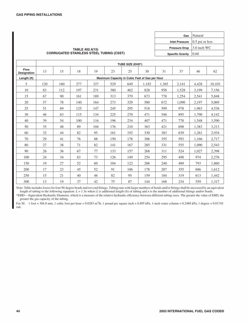
GAS PIPING INSTALLATIONS
44 2003 INTERNATIONAL FUEL GAS CODE®
TUBE SIZE (EHD*)
FlowDesignation 13 15 18 19 23 25 30 31 37 46 62
Length (ft) Maximum Capacity in Cubic Feet of Gas per Hour
5 120 160 277 327 529 649 1,182 1,365 2,141 4,428 10,103
10 83 112 197 231 380 462 828 958 1,528 3,199 7,156
15 67 90 161 189 313 379 673 778 1,254 2,541 5,848
20 57 78 140 164 273 329 580 672 1,090 2,197 5,069
25 51 69 125 147 245 295 518 599 978 1,963 4,536
30 46 63 115 134 225 270 471 546 895 1,790 4,142
40 39 54 100 116 196 234 407 471 778 1,548 3,590
50 35 48 89 104 176 210 363 421 698 1,383 3,213
60 32 44 82 95 161 192 330 383 639 1,261 2,934
70 29 41 76 88 150 178 306 355 593 1,166 2,717
80 27 38 71 82 141 167 285 331 555 1,090 2,543
90 26 36 67 77 133 157 268 311 524 1,027 2,398
100 24 34 63 73 126 149 254 295 498 974 2,276
150 19 27 52 60 104 122 206 240 409 793 1,860
200 17 23 45 52 91 106 178 207 355 686 1,612
250 15 21 40 46 82 95 159 184 319 613 1,442
300 13 19 37 42 75 87 144 168 234 559 1,317
Note: Table includes losses for four 90-degree bends and two end fittings. Tubing runs with larger numbers of bends and/or fittings shall be increased by an equivalentlength of tubing to the following equation: L = 1.3n where L is additional length (ft) of tubing and n is the number of additional fittings and/or bends.
*EHD— Equivalent Hydraulic Diameter, which is a measure of the relative hydraulic efficiency between different tubing sizes. The greater the value of EHD, thegreater the gas capacity of the tubing.
For SI: 1 foot = 304.8 mm, 1 cubic foot per hour = 0.0283 m3/h, 1 pound per square inch = 6.895 kPa, 1-inch water column = 0.2488 kPa, 1 degree = 0.01745rad.
TABLE 402.4(15)CORRUGATED STAINLESS STEEL TUBING (CSST)
Gas Natural
Inlet Pressure 0.5 psi or less
Pressure Drop 3.0 inch WC
Specific Gravity 0.60
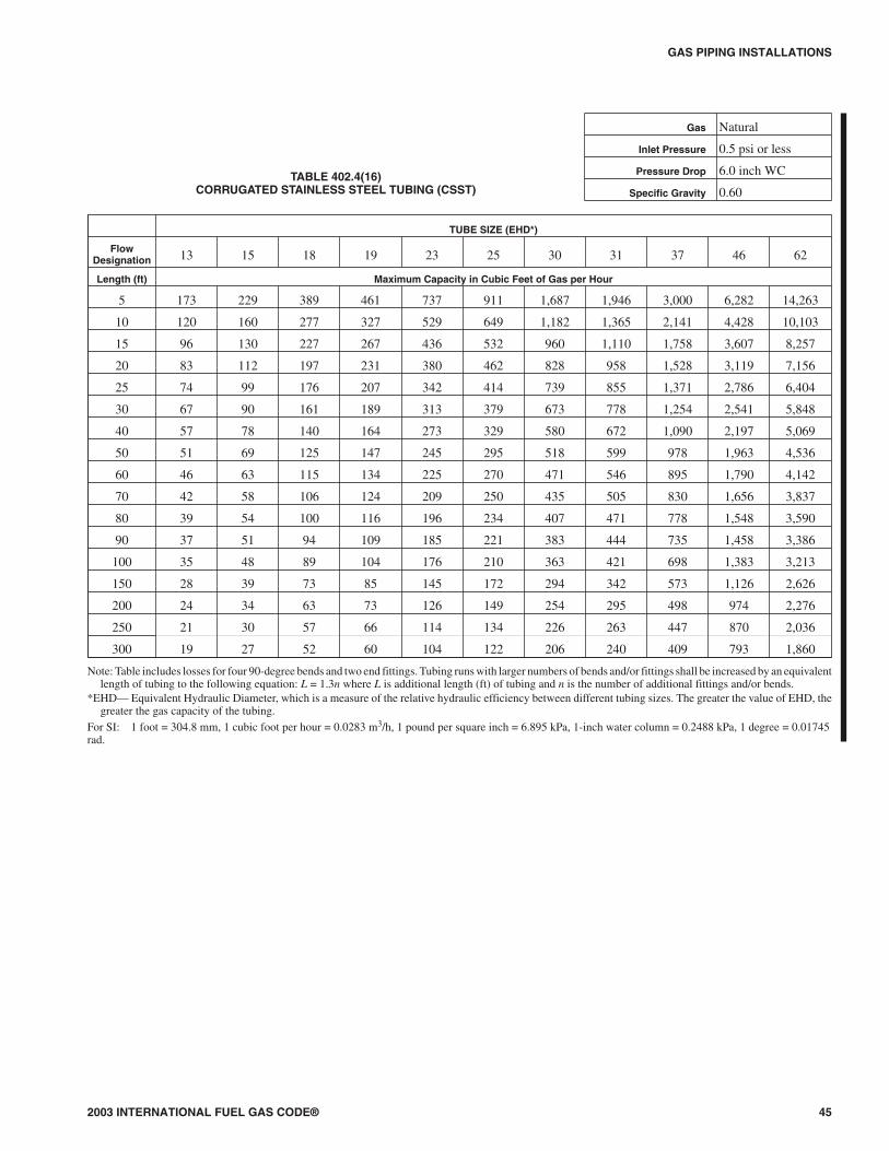
2003 INTERNATIONAL FUEL GAS CODE® 45
GAS PIPING INSTALLATIONS
TUBE SIZE (EHD*)
FlowDesignation 13 15 18 19 23 25 30 31 37 46 62
Length (ft) Maximum Capacity in Cubic Feet of Gas per Hour
5 173 229 389 461 737 911 1,687 1,946 3,000 6,282 14,263
10 120 160 277 327 529 649 1,182 1,365 2,141 4,428 10,103
15 96 130 227 267 436 532 960 1,110 1,758 3,607 8,257
20 83 112 197 231 380 462 828 958 1,528 3,119 7,156
25 74 99 176 207 342 414 739 855 1,371 2,786 6,404
30 67 90 161 189 313 379 673 778 1,254 2,541 5,848
40 57 78 140 164 273 329 580 672 1,090 2,197 5,069
50 51 69 125 147 245 295 518 599 978 1,963 4,536
60 46 63 115 134 225 270 471 546 895 1,790 4,142
70 42 58 106 124 209 250 435 505 830 1,656 3,837
80 39 54 100 116 196 234 407 471 778 1,548 3,590
90 37 51 94 109 185 221 383 444 735 1,458 3,386
100 35 48 89 104 176 210 363 421 698 1,383 3,213
150 28 39 73 85 145 172 294 342 573 1,126 2,626
200 24 34 63 73 126 149 254 295 498 974 2,276
250 21 30 57 66 114 134 226 263 447 870 2,036
300 19 27 52 60 104 122 206 240 409 793 1,860
Note: Table includes losses for four 90-degree bends and two end fittings. Tubing runs with larger numbers of bends and/or fittings shall be increased by an equivalentlength of tubing to the following equation: L = 1.3n where L is additional length (ft) of tubing and n is the number of additional fittings and/or bends.
*EHD— Equivalent Hydraulic Diameter, which is a measure of the relative hydraulic efficiency between different tubing sizes. The greater the value of EHD, thegreater the gas capacity of the tubing.
For SI: 1 foot = 304.8 mm, 1 cubic foot per hour = 0.0283 m3/h, 1 pound per square inch = 6.895 kPa, 1-inch water column = 0.2488 kPa, 1 degree = 0.01745rad.
TABLE 402.4(16)CORRUGATED STAINLESS STEEL TUBING (CSST)
Gas Natural
Inlet Pressure 0.5 psi or less
Pressure Drop 6.0 inch WC
Specific Gravity 0.60

GAS PIPING INSTALLATIONS
46 2003 INTERNATIONAL FUEL GAS CODE®
TABLE 402.4(17)CORRUGATED STAINLESS STEEL TUBING (CSST)
Gas Natural
Inlet Pressure 2.0 psi
Pressure Drop 1.0 psi
Specific Gravity 0.60
TUBE SIZE (EHD*)
FlowDesignation 13 15 18 19 23 25 30 31 37 46 62
Length (ft) Maximum Capacity in Cubic Feet of Gas per Hour
10 270 353 587 700 1,098 1,372 2,592 2,986 4,509 9,599 21,637
25 166 220 374 444 709 876 1,620 1,869 2,887 6,041 13,715
30 151 200 342 405 650 801 1,475 1,703 2,642 5,509 12,526
40 129 172 297 351 567 696 1,273 1,470 2,297 4,763 10,855
50 115 154 266 314 510 624 1,135 1,311 2,061 4,255 9,715
75 93 124 218 257 420 512 922 1,066 1,692 3,467 7,940
80 89 120 211 249 407 496 892 1,031 1,639 3,355 7,689
100 79 107 189 222 366 445 795 920 1,471 2,997 6,881
150 64 87 155 182 302 364 646 748 1,207 2,442 5,624
200 55 75 135 157 263 317 557 645 1,049 2,111 4,874
250 49 67 121 141 236 284 497 576 941 1,886 4,362
300 44 61 110 129 217 260 453 525 862 1,720 3,983
400 38 52 96 111 189 225 390 453 749 1,487 3,452
500 34 46 86 100 170 202 348 404 552 1,329 3,089
Notes:1. Table does not include effect of pressure drop across the line regulator. Where regulator loss exceeds 3/4 psi, DO NOT USE THIS TABLE. Consult with regulator
manufacturer for pressure drops and capacity factors. Pressure drops across a regulator may vary with flow rate.2. CAUTION: Capacities shown in table may exceed maximum capacity for a selected regulator. Consult with regulator or tubing manufacturer for guidance.3. Table includes losses for four 90-degree bends and two end fittings. Tubing runs with larger numbers of bends and/or fittings shall be increased by an equivalent
length of tubing to the following equation: L = 1.3n where L is additional length (ft) of tubing and n is the number of additional fittings and/or bends.*EHD— Equivalent Hydraulic Diameter, which is a measure of the relative hydraulic efficiency between different tubing sizes. The greater the value of EHD, the
greater the gas capacity of the tubing.For SI: 1 foot = 304.8 mm, 1 cubic foot per hour = 0.0283 m3/h, 1 pound per square inch = 6.895 kPa, 1 degree = 0.01745 rad.

2003 INTERNATIONAL FUEL GAS CODE® 47
GAS PIPING INSTALLATIONS
TABLE 402.4(18)CORRUGATED STAINLESS STEEL TUBING (CSST)
Gas Natural
Inlet Pressure 5.0 psi
Pressure Drop 3.5 psi
Specific Gravity 0.60
TUBE SIZE (EHD*)
FlowDesignation 13 15 18 19 23 25 30 31 37 46 62
Length (ft) Maximum Capacity in Cubic Feet of Gas per Hour
10 523 674 1,084 1,304 1,995 2,530 4,923 5,659 8,295 18,080 40,353
25 322 420 691 827 1,289 1,616 3,077 3,543 5,311 11,378 25,580
30 292 382 632 755 1,181 1,478 2,803 3,228 4,860 10,377 23,361
40 251 329 549 654 1,031 1,284 2,418 2,786 4,225 8,972 20,246
50 223 293 492 586 926 1,151 2,157 2,486 3,791 8,015 18,119
75 180 238 403 479 763 944 1,752 2,021 3,112 6,530 14,809
80 174 230 391 463 740 915 1,694 1,955 3,016 6,320 14,341
100 154 205 350 415 665 820 1,511 1,744 2,705 5,646 12,834
150 124 166 287 339 548 672 1,228 1,418 2,221 4,600 10,489
200 107 143 249 294 478 584 1,060 1,224 1,931 3,977 9,090
250 95 128 223 263 430 524 945 1,092 1,732 3,553 8,135
300 86 116 204 240 394 479 860 995 1,585 3,240 7,430
400 74 100 177 208 343 416 742 858 1,378 2,802 6,439
500 66 89 159 186 309 373 662 766 1,035 2,503 5,762
Notes:1. Table does not include effect of pressure drop across the line regulator. Where regulator loss exceeds 3/4 psi, DO NOT USE THIS TABLE. Consult with regulator
manufacturer for pressure drops and capacity factors. Pressure drops across a regulator may vary with flow rate.2. CAUTION: Capacities shown in table may exceed maximum capacity for a selected regulator. Consult with regulator or tubing manufacturer for guidance.3. Table includes losses for four 90-degree bends and two end fittings. Tubing runs with larger numbers of bends and/or fittings shall be increased by an equivalent
length of tubing to the following equation: L = 1.3n where L is additional length (ft) of tubing and n is the number of additional fittings and/or bends.*EHD— Equivalent Hydraulic Diameter, which is a measure of the relative hydraulic efficiency between different tubing sizes. The greater the value of EHD, the
greater the gas capacity of the tubing.For SI: 1 foot = 304.8 mm, 1 cubic foot per hour = 0.0283 m3/h, 1 pound per square inch = 6.895 kPa, 1 degree = 0.01745 rad.
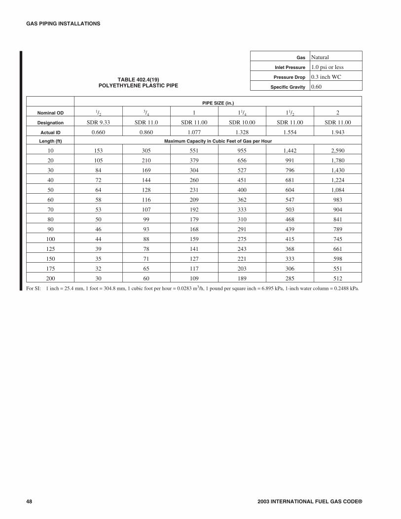
GAS PIPING INSTALLATIONS
48 2003 INTERNATIONAL FUEL GAS CODE®
TABLE 402.4(19)POLYETHYLENE PLASTIC PIPE
Gas Natural
Inlet Pressure 1.0 psi or less
Pressure Drop 0.3 inch WC
Specific Gravity 0.60
PIPE SIZE (in.)
Nominal OD 1/23/4 1 11/4 11/2 2
Designation SDR 9.33 SDR 11.0 SDR 11.00 SDR 10.00 SDR 11.00 SDR 11.00
Actual ID 0.660 0.860 1.077 1.328 1.554 1.943
Length (ft) Maximum Capacity in Cubic Feet of Gas per Hour
10 153 305 551 955 1,442 2,590
20 105 210 379 656 991 1,780
30 84 169 304 527 796 1,430
40 72 144 260 451 681 1,224
50 64 128 231 400 604 1,084
60 58 116 209 362 547 983
70 53 107 192 333 503 904
80 50 99 179 310 468 841
90 46 93 168 291 439 789
100 44 88 159 275 415 745
125 39 78 141 243 368 661
150 35 71 127 221 333 598
175 32 65 117 203 306 551
200 30 60 109 189 285 512
For SI: 1 inch = 25.4 mm, 1 foot = 304.8 mm, 1 cubic foot per hour = 0.0283 m3/h, 1 pound per square inch = 6.895 kPa, 1-inch water column = 0.2488 kPa.

2003 INTERNATIONAL FUEL GAS CODE® 49
GAS PIPING INSTALLATIONS
PIPE SIZE (in.)
Nominal OD 1/23/4 1 11/4 11/2 2
Designation SDR 9.33 SDR 11.0 SDR 11.00 SDR 10.00 SDR 11.00 SDR 11.00
Actual ID 0.660 0.860 1.077 1.328 1.554 1.943
Length (ft) Maximum Capacity in Cubic Feet of Gas per Hour
10 201 403 726 1,258 1,900 3,415
20 138 277 499 865 1,306 2,347
30 111 222 401 695 1,049 1,885
40 95 190 343 594 898 1,613
50 84 169 304 527 796 1,430
60 76 153 276 477 721 1,295
70 70 140 254 439 663 1,192
80 65 131 236 409 617 1,109
90 61 123 221 383 579 1,040
100 58 116 209 362 547 983
125 51 103 185 321 485 871
150 46 93 168 291 439 789
175 43 86 154 268 404 726
200 40 80 144 249 376 675
For SI: 1 inch = 25.4 mm, 1 foot = 304.8 mm, 1 cubic foot per hour = 0.0283 m3/h, 1 pound per square inch = 6.895 kPa, 1-inch water column = 0.2488 kPa.
TABLE 402.4(20)POLYETHYLENE PLASTIC PIPE
Gas Natural
Inlet Pressure 1.0 psi or less
Pressure Drop 0.5 inch WC
Specific Gravity 0.60

GAS PIPING INSTALLATIONS
50 2003 INTERNATIONAL FUEL GAS CODE®
TABLE 402.4(21)POLYETHYLENE PLASTIC PIPE
Gas Natural
Inlet Pressure 2.0 psi
Pressure Drop 1.0 psi
Specific Gravity 0.60
PIPE SIZE (in.)
Nominal OD 1/23/4 1 11/4 11/2 2
Designation SDR 9.33 SDR 11.0 SDR 11.00 SDR 10.00 SDR 11.00 SDR 11.00
Actual ID 0.660 0.860 1.077 1.328 1.554 1.943
Length (ft) Maximum Capacity in Cubic Feet of Gas per Hour
10 1,858 3,721 6,714 11,631 17,565 31,560
20 1,277 2,557 4,614 7,994 12,072 21,691
30 1,026 2,054 3,706 6,420 9,695 17,419
40 878 1,758 3,172 5,494 8,297 14,908
50 778 1,558 2,811 4,869 7,354 13,213
60 705 1,412 2,547 4,412 6,663 11,972
70 649 1,299 2,343 4,059 6,130 11,014
80 603 1,208 2,180 3,776 5,703 10,246
90 566 1,134 2,045 3,543 5,351 9,614
100 535 1,071 1,932 3,347 5,054 9,081
125 474 949 1,712 2,966 4,479 8,048
150 429 860 1,551 2,688 4,059 7,292
175 395 791 1,427 2,473 3,734 6,709
200 368 736 1,328 2,300 3,474 6,241
For SI: 1 inch = 25.4 mm, 1 foot = 304.8 mm, 1 cubic foot per hour = 0.0283 m3/h, 1 pound per square inch = 6.895 kPa.
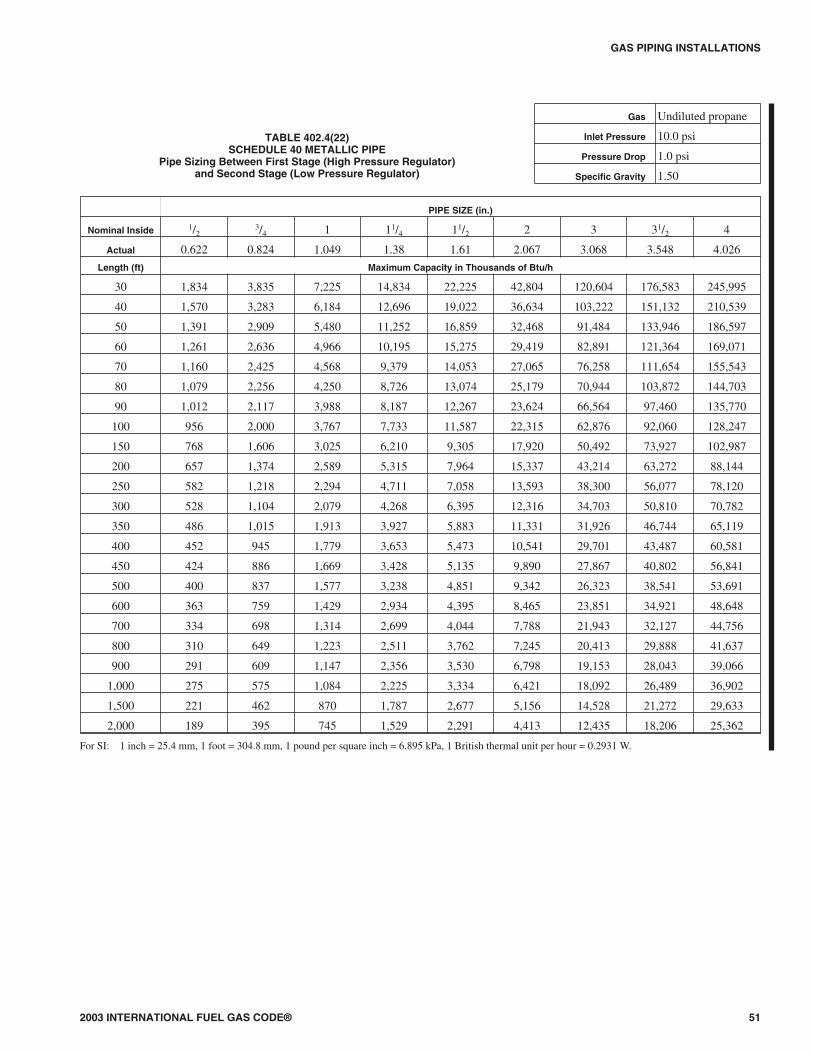
2003 INTERNATIONAL FUEL GAS CODE® 51
GAS PIPING INSTALLATIONS
TABLE 402.4(22)SCHEDULE 40 METALLIC PIPE
Pipe Sizing Between First Stage (High Pressure Regulator)and Second Stage (Low Pressure Regulator)
Gas Undiluted propane
Inlet Pressure 10.0 psi
Pressure Drop 1.0 psi
Specific Gravity 1.50
PIPE SIZE (in.)
Nominal Inside 1/23/4 1 11/4 11/2 2 3 31/2 4
Actual 0.622 0.824 1.049 1.38 1.61 2.067 3.068 3.548 4.026
Length (ft) Maximum Capacity in Thousands of Btu/h
30 1,834 3,835 7,225 14,834 22,225 42,804 120,604 176,583 245,995
40 1,570 3,283 6,184 12,696 19,022 36,634 103,222 151,132 210,539
50 1,391 2,909 5,480 11,252 16,859 32,468 91,484 133,946 186,597
60 1,261 2,636 4,966 10,195 15,275 29,419 82,891 121,364 169,071
70 1,160 2,425 4,568 9,379 14,053 27,065 76,258 111,654 155,543
80 1,079 2,256 4,250 8,726 13,074 25,179 70,944 103,872 144,703
90 1,012 2,117 3,988 8,187 12,267 23,624 66,564 97,460 135,770
100 956 2,000 3,767 7,733 11,587 22,315 62,876 92,060 128,247
150 768 1,606 3,025 6,210 9,305 17,920 50,492 73,927 102,987
200 657 1,374 2,589 5,315 7,964 15,337 43,214 63,272 88,144
250 582 1,218 2,294 4,711 7,058 13,593 38,300 56,077 78,120
300 528 1,104 2,079 4,268 6,395 12,316 34,703 50,810 70,782
350 486 1,015 1,913 3,927 5,883 11,331 31,926 46,744 65,119
400 452 945 1,779 3,653 5,473 10,541 29,701 43,487 60,581
450 424 886 1,669 3,428 5,135 9,890 27,867 40,802 56,841
500 400 837 1,577 3,238 4,851 9,342 26,323 38,541 53,691
600 363 759 1,429 2,934 4,395 8,465 23,851 34,921 48,648
700 334 698 1,314 2,699 4,044 7,788 21,943 32,127 44,756
800 310 649 1,223 2,511 3,762 7,245 20,413 29,888 41,637
900 291 609 1,147 2,356 3,530 6,798 19,153 28,043 39,066
1,000 275 575 1,084 2,225 3,334 6,421 18,092 26,489 36,902
1,500 221 462 870 1,787 2,677 5,156 14,528 21,272 29,633
2,000 189 395 745 1,529 2,291 4,413 12,435 18,206 25,362
For SI: 1 inch = 25.4 mm, 1 foot = 304.8 mm, 1 pound per square inch = 6.895 kPa, 1 British thermal unit per hour = 0.2931 W.

GAS PIPING INSTALLATIONS
52 2003 INTERNATIONAL FUEL GAS CODE®
TABLE 402.4(23)SCHEDULE 40 METALLIC PIPE
Gas Undiluted propane
Inlet Pressure 2.0 psi
Pressure Drop 1.0 psi
Specific Gravity 1.50
PIPE SIZE (in.)
Nominal 1/23/4 1 11/4 11/2 2 21/2 3 4
Actual ID 0.622 0.824 1.049 1.380 1.610 2.067 2.469 3.068 4.026
Length (ft) Maximum Capacity in Thousands of Btu/h
10 2,676 5,595 10,539 21,638 32,420 62,438 99,516 175,927 358,835
20 1,839 3,845 7,243 14,872 22,282 42,913 68,397 120,914 246,625
30 1,477 3,088 5,817 11,942 17,893 34,461 54,925 97,098 198,049
40 1,264 2,643 4,978 10,221 15,314 29,494 47,009 83,103 169,504
50 1,120 2,342 4,412 9,059 13,573 26,140 41,663 73,653 150,229
60 1,015 2,122 3,998 8,208 12,298 23,685 37,750 66,735 136,118
70 934 1,952 3,678 7,551 11,314 21,790 34,729 61,395 125,227
80 869 1,816 3,422 7,025 10,526 20,271 32,309 57,116 116,499
90 815 1,704 3,210 6,591 9,876 19,020 30,314 53,590 109,307
100 770 1,610 3,033 6,226 9,329 17,966 28,635 50,621 103,251
125 682 1,427 2,688 5,518 8,268 15,923 25,378 44,865 91,510
150 618 1,293 2,435 5,000 7,491 14,427 22,995 40,651 82,914
175 569 1,189 2,240 4,600 6,892 13,273 21,155 37,398 76,280
200 529 1,106 2,084 4,279 6,411 12,348 19,681 34,792 70,964
For SI: 1 inch = 25.4 mm, 1 foot = 304.8 mm, 1 pound per square inch = 6.895 kPa, 1 British thermal unit per hour = 0.2931 W.

2003 INTERNATIONAL FUEL GAS CODE® 53
GAS PIPING INSTALLATIONS
PIPE SIZE (in.)
Nominal Inside 1/23/4 1 11/4 11/2 2 3 31/2 4
Actual 0.622 0.824 1.049 1.38 1.61 2.067 3.068 3.548 4.026
Length (ft) Maximum Capacity in Thousands of Btu/h
10 291 608 1,145 2,352 3,523 6,786 19,119 27,993 38,997
20 200 418 787 1,616 2,422 4,664 13,141 19,240 26,802
30 160 336 632 1,298 1,945 3,745 10,552 15,450 21,523
40 137 287 541 1,111 1,664 3,205 9,031 13,223 18,421
50 122 255 480 984 1,475 2,841 8,004 11,720 16,326
60 110 231 434 892 1,337 2,574 7,253 10,619 14,793
80 94 197 372 763 1,144 2,203 6,207 9,088 12,661
100 84 175 330 677 1,014 1,952 5,501 8,055 11,221
125 74 155 292 600 899 1,730 4,876 7,139 9,945
150 67 140 265 543 814 1,568 4,418 6,468 9,011
200 58 120 227 465 697 1,342 3,781 5,536 7,712
250 51 107 201 412 618 1,189 3,351 4,906 6,835
300 46 97 182 373 560 1,078 3,036 4,446 6,193
350 42 89 167 344 515 991 2,793 4,090 5,698
400 40 83 156 320 479 922 2,599 3,805 5,301
For SI: 1 inch = 25.4 mm, 1 foot = 304.8 mm, 1-inch water column = 0.2488 kPa, 1 British thermal unit per hour = 0.2931 W.
TABLE 402.4(24)SCHEDULE 40 METALLIC PIPE
Pipe Sizing Between Single or Second Stage(Low Pressure Regulator) and Appliance
Gas Undiluted propane
Inlet Pressure 11.0 inch WC
Pressure Drop 0.5 inch WC
Specific Gravity 1.50
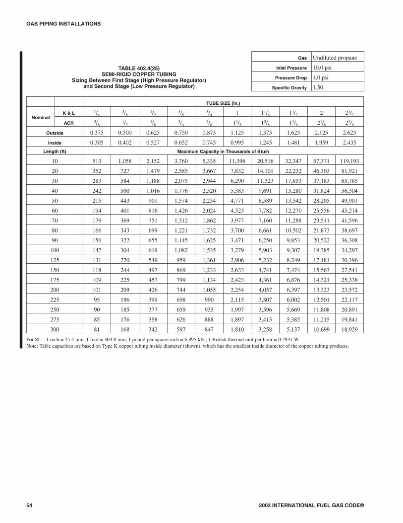
GAS PIPING INSTALLATIONS
54 2003 INTERNATIONAL FUEL GAS CODE®
TUBE SIZE (in.)
NominalK & L 1/4
3/81/2
5/83/4 1 11/4 11/2 2 21/2
ACR 3/81/2
5/83/4
7/8 11/8 13/8 15/8 21/8 25/8
Outside 0.375 0.500 0.625 0.750 0.875 1.125 1.375 1.625 2.125 2.625
Inside 0.305 0.402 0.527 0.652 0.745 0.995 1.245 1.481 1.959 2.435
Length (ft) Maximum Capacity in Thousands of Btu/h
10 513 1,058 2,152 3,760 5,335 11,396 20,516 32,347 67,371 119,193
20 352 727 1,479 2,585 3,667 7,832 14,101 22,232 46,303 81,921
30 283 584 1,188 2,075 2,944 6,290 11,323 17,853 37,183 65,785
40 242 500 1,016 1,776 2,520 5,383 9,691 15,280 31,824 56,304
50 215 443 901 1,574 2,234 4,771 8,589 13,542 28,205 49,901
60 194 401 816 1,426 2,024 4,323 7,782 12,270 25,556 45,214
70 179 369 751 1,312 1,862 3,977 7,160 11,288 23,511 41,596
80 166 343 699 1,221 1,732 3,700 6,661 10,502 21,873 38,697
90 156 322 655 1,145 1,625 3,471 6,250 9,853 20,522 36,308
100 147 304 619 1,082 1,535 3,279 5,903 9,307 19,385 34,297
125 131 270 549 959 1,361 2,906 5,232 8,249 17,181 30,396
150 118 244 497 869 1,233 2,633 4,741 7,474 15,567 27,541
175 109 225 457 799 1,134 2,423 4,361 6,876 14,321 25,338
200 101 209 426 744 1,055 2,254 4,057 6,397 13,323 23,572
225 95 196 399 698 990 2,115 3,807 6,002 12,501 22,117
250 90 185 377 659 935 1,997 3,596 5,669 11,808 20,891
275 85 176 358 626 888 1,897 3,415 5,385 11,215 19,841
300 81 168 342 597 847 1,810 3,258 5,137 10,699 18,929
For SI: 1 inch = 25.4 mm, 1 foot = 304.8 mm, 1 pound per square inch = 6.895 kPa, 1 British thermal unit per hour = 0.2931 W.Note: Table capacities are based on Type K copper tubing inside diameter (shown), which has the smallest inside diameter of the copper tubing products.
TABLE 402.4(25)SEMI-RIGID COPPER TUBING
Sizing Between First Stage (High Pressure Regulator)and Second Stage (Low Pressure Regulator)
Gas Undiluted propane
Inlet Pressure 10.0 psi
Pressure Drop 1.0 psi
Specific Gravity 1.50
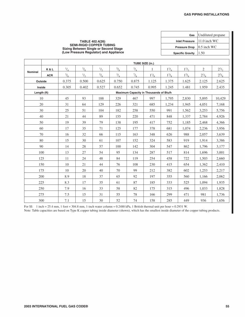
2003 INTERNATIONAL FUEL GAS CODE® 55
GAS PIPING INSTALLATIONS
TABLE 402.4(26)SEMI-RIGID COPPER TUBING
Sizing Between Single or Second Stage(Low Pressure Regulator) and Appliance
Gas Undiluted propane
Inlet Pressure 11.0 inch WC
Pressure Drop 0.5 inch WC
Specific Gravity 1.50
TUBE SIZE (in.)
NominalK & L 1/4
3/81/2
5/83/4 1 11/4 11/2 2 21/2
ACR 3/81/2
5/83/4
7/8 11/8 13/8 15/8 21/8 25/8
Outside 0.375 0.500 0.625 0.750 0.875 1.125 1.375 1.625 2.125 2.625
Inside 0.305 0.402 0.527 0.652 0.745 0.995 1.245 1.481 1.959 2.435
Length (ft) Maximum Capacity in Thousands of Btu/h
10 45 93 188 329 467 997 1,795 2,830 5,895 10,429
20 31 64 129 226 321 685 1,234 1,945 4,051 7,168
30 25 51 104 182 258 550 991 1,562 3,253 5,756
40 21 44 89 155 220 471 848 1,337 2,784 4,926
50 19 39 79 138 195 417 752 1,185 2,468 4,366
60 17 35 71 125 177 378 681 1,074 2,236 3,956
70 16 32 66 115 163 348 626 988 2,057 3,639
80 15 30 61 107 152 324 583 919 1,914 3,386
90 14 28 57 100 142 304 547 862 1,796 3,177
100 13 27 54 95 134 287 517 814 1,696 3,001
125 11 24 48 84 119 254 458 722 1,503 2,660
150 10 21 44 76 108 230 415 654 1,362 2,410
175 10 20 40 70 99 212 382 602 1,253 2,217
200 8.9 18 37 65 92 197 355 560 1,166 2,062
225 8.3 17 35 61 87 185 333 525 1,094 1,935
250 7.9 16 33 58 82 175 315 496 1,033 1,828
275 7.5 15 31 55 78 166 299 471 981 1,736
300 7.1 15 30 52 74 158 285 449 936 1,656
For SI: 1 inch = 25.4 mm, 1 foot = 304.8 mm, 1-inch water column = 0.2488 kPa, 1 British thermal unit per hour = 0.2931 W.Note: Table capacities are based on Type K copper tubing inside diameter (shown), which has the smallest inside diameter of the copper tubing products.
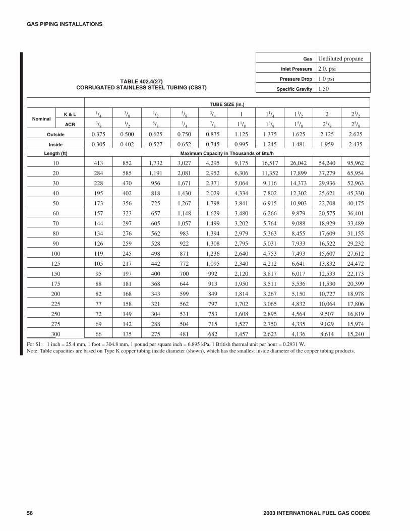
GAS PIPING INSTALLATIONS
56 2003 INTERNATIONAL FUEL GAS CODE®
TABLE 402.4(27)CORRUGATED STAINLESS STEEL TUBING (CSST)
Gas Undiluted propane
Inlet Pressure 2.0. psi
Pressure Drop 1.0 psi
Specific Gravity 1.50
TUBE SIZE (in.)
NominalK & L 1/4
3/81/2
5/83/4 1 11/4 11/2 2 21/2
ACR 3/81/2
5/83/4
7/8 11/8 13/8 15/8 21/8 25/8
Outside 0.375 0.500 0.625 0.750 0.875 1.125 1.375 1.625 2.125 2.625
Inside 0.305 0.402 0.527 0.652 0.745 0.995 1.245 1.481 1.959 2.435
Length (ft) Maximum Capacity in Thousands of Btu/h
10 413 852 1,732 3,027 4,295 9,175 16,517 26,042 54,240 95,962
20 284 585 1,191 2,081 2,952 6,306 11,352 17,899 37,279 65,954
30 228 470 956 1,671 2,371 5,064 9,116 14,373 29,936 52,963
40 195 402 818 1,430 2,029 4,334 7,802 12,302 25,621 45,330
50 173 356 725 1,267 1,798 3,841 6,915 10,903 22,708 40,175
60 157 323 657 1,148 1,629 3,480 6,266 9,879 20,575 36,401
70 144 297 605 1,057 1,499 3,202 5,764 9,088 18,929 33,489
80 134 276 562 983 1,394 2,979 5,363 8,455 17,609 31,155
90 126 259 528 922 1,308 2,795 5,031 7,933 16,522 29,232
100 119 245 498 871 1,236 2,640 4,753 7,493 15,607 27,612
125 105 217 442 772 1,095 2,340 4,212 6,641 13,832 24,472
150 95 197 400 700 992 2,120 3,817 6,017 12,533 22,173
175 88 181 368 644 913 1,950 3,511 5,536 11,530 20,399
200 82 168 343 599 849 1,814 3,267 5,150 10,727 18,978
225 77 158 321 562 797 1,702 3,065 4,832 10,064 17,806
250 72 149 304 531 753 1,608 2,895 4,564 9,507 16,819
275 69 142 288 504 715 1,527 2,750 4,335 9,029 15,974
300 66 135 275 481 682 1,457 2,623 4,136 8,614 15,240
For SI: 1 inch = 25.4 mm, 1 foot = 304.8 mm, 1 pound per square inch = 6.895 kPa, 1 British thermal unit per hour = 0.2931 W.Note: Table capacities are based on Type K copper tubing inside diameter (shown), which has the smallest inside diameter of the copper tubing products.
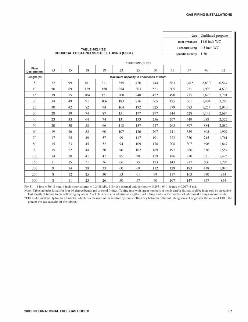
2003 INTERNATIONAL FUEL GAS CODE® 57
GAS PIPING INSTALLATIONS
TUBE SIZE (EHD*)
FlowDesignation 13 15 18 19 23 25 30 31 37 46 62
Length (ft) Maximum Capacity in Thousands of Btu/h
5 72 99 181 211 355 426 744 863 1,415 2,830 6,547
10 50 69 129 150 254 303 521 605 971 1,993 4,638
15 39 55 104 121 208 248 422 490 775 1,623 3,791
20 34 49 91 106 183 216 365 425 661 1,404 3,285
25 30 42 82 94 164 192 325 379 583 1,254 2,940
30 28 39 74 87 151 177 297 344 528 1,143 2,684
40 23 33 64 74 131 153 256 297 449 988 2,327
50 20 30 58 66 118 137 227 265 397 884 2,082
60 19 26 53 60 107 126 207 241 359 805 1,902
70 17 25 49 57 99 117 191 222 330 745 1,761
80 15 23 45 52 94 109 178 208 307 696 1,647
90 15 22 44 50 90 102 169 197 286 656 1,554
100 14 20 41 47 85 98 159 186 270 621 1,475
150 11 15 31 36 66 75 123 143 217 506 1,205
200 9 14 28 33 60 69 112 129 183 438 1,045
250 8 12 25 30 53 61 99 117 163 390 934
300 8 11 23 26 50 57 90 107 147 357 854
For SI: 1 foot = 304.8 mm, 1-inch water column = 0.2488 kPa, 1 British thermal unit per hour = 0.2931 W, 1 degree = 0.01745 rad.Note: Table includes losses for four 90-degree bends and two end fittings. Tubing runs with larger numbers of bends and/or fittings shall be increased by an equiva-
lent length of tubing to the following equation: L = 1.3n where L is additional length (ft) of tubing and n is the number of additional fittings and/or bends.*EHD—Equivalent Hydraulic Diameter, which is a measure of the relative hydraulic efficiency between different tubing sizes. The greater the value of EHD, the
greater the gas capacity of the tubing.
TABLE 402.4(28)CORRUGATED STAINLESS STEEL TUBING (CSST)
Gas Undiluted propane
Inlet Pressure 11.0 inch WC
Pressure Drop 0.5 inch WC
Specific Gravity 1.50

GAS PIPING INSTALLATIONS
58 2003 INTERNATIONAL FUEL GAS CODE®
TUBE SIZE (EHD*)
FlowDesignation 13 15 18 19 23 25 30 31 37 46 62
Length (ft) Maximum Capacity in Thousands of Btu/h
10 426 558 927 1,106 1,735 2,168 4,097 4,720 7,128 15,174 34,203
25 262 347 591 701 1,120 1,384 2,560 2,954 4,564 9,549 21,680
30 238 316 540 640 1,027 1,266 2,331 2,692 4,176 8,708 19,801
40 203 271 469 554 896 1,100 2,012 2,323 3,631 7,529 17,159
50 181 243 420 496 806 986 1,794 2,072 3,258 6,726 15,357
75 147 196 344 406 663 809 1,457 1,685 2,675 5,480 12,551
80 140 189 333 393 643 768 1,410 1,629 2,591 5,303 12,154
100 124 169 298 350 578 703 1,256 1,454 2,325 4,738 10,877
150 101 137 245 287 477 575 1,021 1,182 1,908 3,860 8,890
200 86 118 213 248 415 501 880 1,019 1,658 3,337 7,705
250 77 105 191 222 373 448 785 910 1,487 2,981 6,895
300 69 96 173 203 343 411 716 829 1,363 2,719 6,296
400 60 82 151 175 298 355 616 716 1,163 2,351 5,457
500 53 72 135 158 268 319 550 638 1,027 2,101 4,883
For SI: 1 foot = 304.8 mm, 1 pound per square inch = 6.895 kPa, 1-inch water column = 0.2488 kPa, 1 British thermal unit per hour = 0.2931 W, 1 degree =0.01745 rad.Notes:1. Table does not include effect of pressure drop across the line regulator. Where regulator loss exceeds 1/2 psi (based on 13 in. w.c. outlet pressure), DO NOT USE
THIS TABLE. Consult with regulator manufacturer for pressure drops and capacity factors. Pressure drops across a regulator may vary with flow rate.2. CAUTION: Capacities shown in table may exceed maximum capacity for a selected regulator. Consult with regulator or tubing manufacturer for guidance.3. Table includes losses for four 90-degree bends and two end fittings. Tubing runs with larger numbers of bends and/or fittings shall be increased by an equivalent
length of tubing to the following equation: L = 1.3n where L is additional length (ft) of tubing and n is the number of additional fittings and/or bends.*EHD—Equivalent Hydraulic Diameter, which is a measure of the relative hydraulic efficiency between different tubing sizes. The greater the value of EHD, the
greater the gas capacity of the tubing.
TABLE 402.4(29)CORRUGATED STAINLESS STEEL TUBING (CSST)
Gas Undiluted propane
Inlet Pressure 2.0 psi
Pressure Drop 1.0 psi
Specific Gravity 1.50
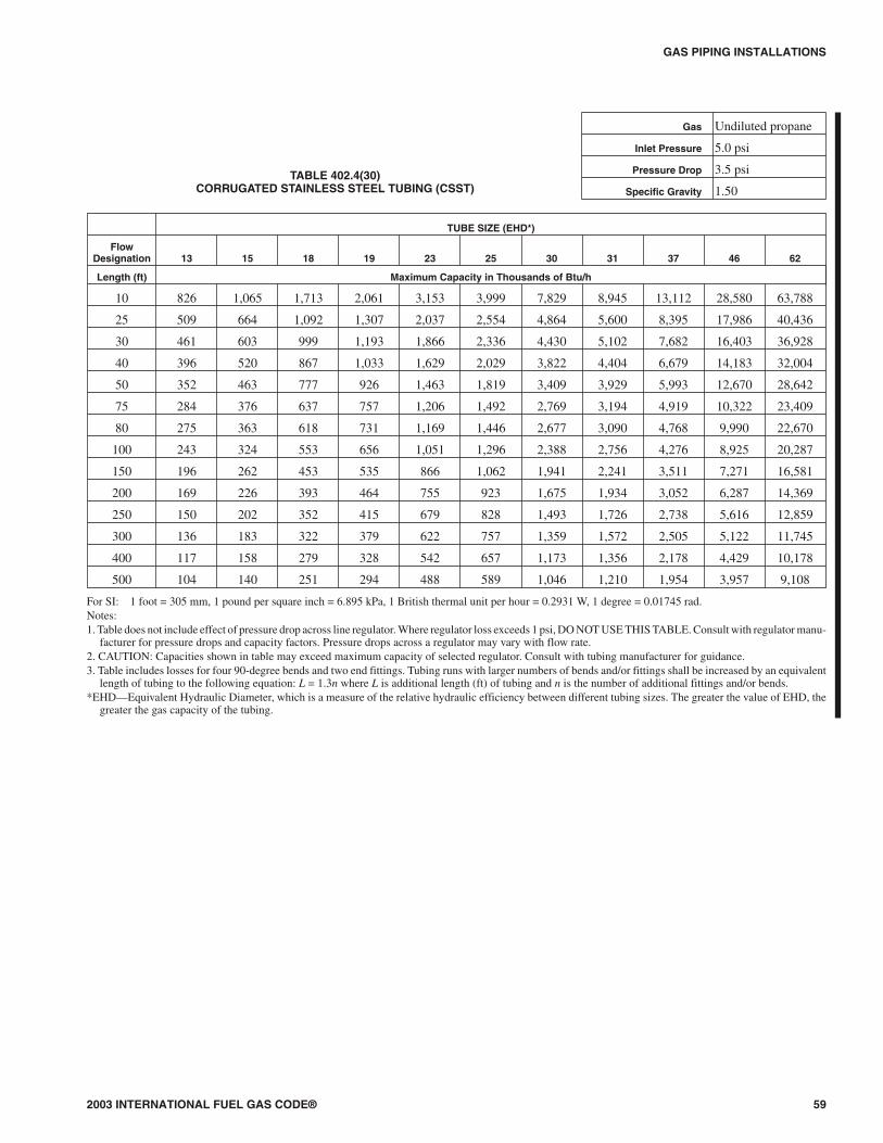
2003 INTERNATIONAL FUEL GAS CODE® 59
GAS PIPING INSTALLATIONS
TUBE SIZE (EHD*)
FlowDesignation 13 15 18 19 23 25 30 31 37 46 62
Length (ft) Maximum Capacity in Thousands of Btu/h
10 826 1,065 1,713 2,061 3,153 3,999 7,829 8,945 13,112 28,580 63,788
25 509 664 1,092 1,307 2,037 2,554 4,864 5,600 8,395 17,986 40,436
30 461 603 999 1,193 1,866 2,336 4,430 5,102 7,682 16,403 36,928
40 396 520 867 1,033 1,629 2,029 3,822 4,404 6,679 14,183 32,004
50 352 463 777 926 1,463 1,819 3,409 3,929 5,993 12,670 28,642
75 284 376 637 757 1,206 1,492 2,769 3,194 4,919 10,322 23,409
80 275 363 618 731 1,169 1,446 2,677 3,090 4,768 9,990 22,670
100 243 324 553 656 1,051 1,296 2,388 2,756 4,276 8,925 20,287
150 196 262 453 535 866 1,062 1,941 2,241 3,511 7,271 16,581
200 169 226 393 464 755 923 1,675 1,934 3,052 6,287 14,369
250 150 202 352 415 679 828 1,493 1,726 2,738 5,616 12,859
300 136 183 322 379 622 757 1,359 1,572 2,505 5,122 11,745
400 117 158 279 328 542 657 1,173 1,356 2,178 4,429 10,178
500 104 140 251 294 488 589 1,046 1,210 1,954 3,957 9,108
For SI: 1 foot = 305 mm, 1 pound per square inch = 6.895 kPa, 1 British thermal unit per hour = 0.2931 W, 1 degree = 0.01745 rad.Notes:1. Table does not include effect of pressure drop across line regulator. Where regulator loss exceeds 1 psi, DO NOT USE THIS TABLE. Consult with regulator manu-
facturer for pressure drops and capacity factors. Pressure drops across a regulator may vary with flow rate.2. CAUTION: Capacities shown in table may exceed maximum capacity of selected regulator. Consult with tubing manufacturer for guidance.3. Table includes losses for four 90-degree bends and two end fittings. Tubing runs with larger numbers of bends and/or fittings shall be increased by an equivalent
length of tubing to the following equation: L = 1.3n where L is additional length (ft) of tubing and n is the number of additional fittings and/or bends.*EHD—Equivalent Hydraulic Diameter, which is a measure of the relative hydraulic efficiency between different tubing sizes. The greater the value of EHD, the
greater the gas capacity of the tubing.
TABLE 402.4(30)CORRUGATED STAINLESS STEEL TUBING (CSST)
Gas Undiluted propane
Inlet Pressure 5.0 psi
Pressure Drop 3.5 psi
Specific Gravity 1.50
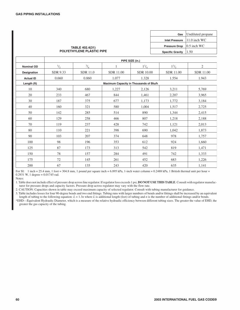
GAS PIPING INSTALLATIONS
60 2003 INTERNATIONAL FUEL GAS CODE®
PIPE SIZE (in.)
Nominal OD 1/23/4 1 11/4 11/2 2
Designation SDR 9.33 SDR 11.0 SDR 11.00 SDR 10.00 SDR 11.00 SDR 11.00
Actual ID 0.660 0.860 1.077 1.328 1.554 1.943
Length (ft) Maximum Capacity in Thousands of Btu/h
10 340 680 1,227 2,126 3,211 5,769
20 233 467 844 1,461 2,207 3,965
30 187 375 677 1,173 1,772 3,184
40 160 321 580 1,004 1,517 2,725
50 142 285 514 890 1,344 2,415
60 129 258 466 807 1,218 2,188
70 119 237 428 742 1,121 2,013
80 110 221 398 690 1,042 1,873
90 103 207 374 648 978 1,757
100 98 196 353 612 924 1,660
125 87 173 313 542 819 1,471
150 78 157 284 491 742 1,333
175 72 145 261 452 683 1,226
200 67 135 243 420 635 1,141
For SI: 1 inch = 25.4 mm, 1 foot = 304.8 mm, 1 pound per square inch = 6.895 kPa, 1-inch water column = 0.2488 kPa, 1 British thermal unit per hour =0.2931 W, 1 degree = 0.01745 rad.Notes:1. Table does not include effect of pressure drop across line regulator. If regulator loss exceeds 1 psi, DO NOT USE THIS TABLE. Consult with regulator manufac-
turer for pressure drops and capacity factors. Pressure drop across regulator may vary with the flow rate.2. CAUTION: Capacities shown in table may exceed maximum capacity of selected regulator. Consult with tubing manufacturer for guidance.3. Table includes losses for four 90-degree bends and two end fittings. Tubing runs with larger numbers of bends and/or fittings shall be increased by an equivalent
length of tubing to the following equation: L = 1.3n where L is additional length (feet) of tubing and n is the number of additional fittings and/or bends.*EHD—Equivalent Hydraulic Diameter, which is a measure of the relative hydraulic efficiency between different tubing sizes. The greater the value of EHD, the
greater the gas capacity of the tubing.
TABLE 402.4(31)POLYETHYLENE PLASTIC PIPE
Gas Undiluted propane
Inlet Pressure 11.0 inch WC
Pressure Drop 0.5 inch WC
Specific Gravity 1.50
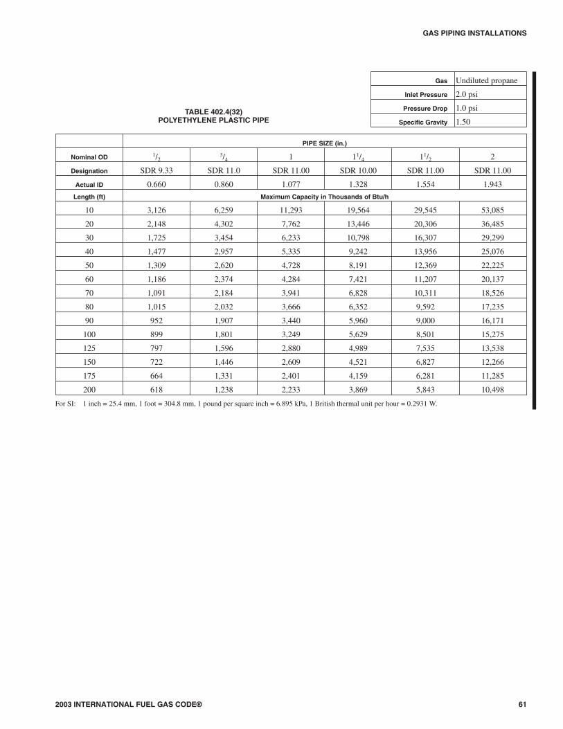
2003 INTERNATIONAL FUEL GAS CODE® 61
GAS PIPING INSTALLATIONS
PIPE SIZE (in.)
Nominal OD 1/23/4 1 11/4 11/2 2
Designation SDR 9.33 SDR 11.0 SDR 11.00 SDR 10.00 SDR 11.00 SDR 11.00
Actual ID 0.660 0.860 1.077 1.328 1.554 1.943
Length (ft) Maximum Capacity in Thousands of Btu/h
10 3,126 6,259 11,293 19,564 29,545 53,085
20 2,148 4,302 7,762 13,446 20,306 36,485
30 1,725 3,454 6,233 10,798 16,307 29,299
40 1,477 2,957 5,335 9,242 13,956 25,076
50 1,309 2,620 4,728 8,191 12,369 22,225
60 1,186 2,374 4,284 7,421 11,207 20,137
70 1,091 2,184 3,941 6,828 10,311 18,526
80 1,015 2,032 3,666 6,352 9,592 17,235
90 952 1,907 3,440 5,960 9,000 16,171
100 899 1,801 3,249 5,629 8,501 15,275
125 797 1,596 2,880 4,989 7,535 13,538
150 722 1,446 2,609 4,521 6,827 12,266
175 664 1,331 2,401 4,159 6,281 11,285
200 618 1,238 2,233 3,869 5,843 10,498
For SI: 1 inch = 25.4 mm, 1 foot = 304.8 mm, 1 pound per square inch = 6.895 kPa, 1 British thermal unit per hour = 0.2931 W.
TABLE 402.4(32)POLYETHYLENE PLASTIC PIPE
Gas Undiluted propane
Inlet Pressure 2.0 psi
Pressure Drop 1.0 psi
Specific Gravity 1.50

GAS PIPING INSTALLATIONS
62 2003 INTERNATIONAL FUEL GAS CODE®
PLASTIC TUBING SIZE (CTS) (in.)
Nominal OD 1/23/4
Designation SDR 7.00 SDR 11.00
Actual ID 0.445 0.927
Length (ft) Maximum Capacity in Thousands of Btu/h
10 121 828
20 83 569
30 67 457
40 57 391
50 51 347
60 46 314
70 42 289
80 39 269
90 37 252
100 35 238
125 31 211
150 28 191
175 26 176
200 24 164
225 22 154
250 21 145
275 20 138
300 19 132
350 18 121
400 16 113
For SI: 1 inch = 25.4 mm, 1 foot = 304.8 mm, 1 British thermal unit per hour = 0.2931 W, 1-inch water column = 0.2488 kPa.
TABLE 402.4(33)POLYETHYLENE PLASTIC TUBING
Gas Undiluted propane
Inlet pressure 11.0 inch WC
Pressure Drop 0.5 inch WC
Specific Gravity 1.50

GAS PIPING INSTALLATIONS
SECTION 403 (IFGS) PIPING MATERIALS
403.1 General. Materials used for piping systems shall comply with the requirements of this chapter or shall be approved. 403.2 Used materials. Pipe, fittings, valves and other materials shall not be used again except where they are free of foreign materials and have been ascertained to be adequate for the service intended. 403.3 Other materials. Material not covered by the standards specifications listed herein shall be investigated and tested to determine that it is safe and suitable for the proposed service, and, in addition, shall be recommended for that service by the manufacturer and shall be approved by the code official. 403.4 Metallic pipe. Metallic pipe shall comply with Sections 403.4.1 through 403.4.4.
403.4.1 Cast iron. Cast-iron pipe shall not be used. 403.4.2 Steel. Steel and wrought-iron pipe shall be at least of standard weight (Schedule 40) and shall comply with one of the following standards:
1. ASME B 36.10, 10M 2. ASTM A 53; or 3. ASTM A 106.
403.4.3 Copper and brass. Copper and brass pipe shall not be used if the gas contains more than an average of 0.3 grains of hydrogen sulfide per 100 standard cubic feet of gas (0.7 milligrams per 100 liters). Threaded copper, brass and aluminum-alloy pipe shall not be used with gases corrosive to such materials. 403.4.4 Aluminum. Aluminum-alloy pipe shall comply with ASTMB241 (except that the use of alloy 5456 is prohibited), and shall be marked at each end of each length indicating compliance. Aluminum-alloy pipe shall be coated to protect against external corrosion where it is in contact with masonry, plaster, or insulation, or is subject to repeated wettings by such liquids as water, detergents, or sewage. Aluminum-alloy pipe shall not be used in exterior locations or underground.
403.5 Metallic tubing. Seamless copper, aluminum alloy and steel tubing shall not be used with gases corrosive to such materials.
403.5.1 Steel tubing. Steel tubing shall comply with ASTM A 254 or ASTM A 539. 403.5.2 Copper and brass tubing. Copper tubing shall comply with Standard Type K or L of ASTM B 88 or ASTM B 280.
Copper and brass tubing shall not be used if the gas contains more than an average of 0.3 grains of hydrogen sulfide per 100 standard cubic feet of gas (0.7 milligrams per 100 liters). 403.5.3 Aluminum tubing. Aluminum-alloy tubing shall comply with ASTM B 210 or ASTM B 241. Aluminum-alloy tubing shall be coated to protect against external corrosion where it is in contact with masonry, plaster or insulation, or is subject to repeated wettings by such liquids as water, detergent or sewage.
Aluminum-alloy tubing shall not be used in exterior locations or underground. 403.5.4 Corrugated stainless steel tubing. Corrugated stainless steel tubing shall be tested and listed in compliance with the construction, installation and performance requirements of ANSI LC 1/CSA 6.26.
403.6 Plastic pipe, tubing and fittings. Plastic pipe, tubing and fittings shall be used outside, underground, only, and shall conform
to ASTM D 2513. Pipe shall be marked “gas” and “ASTM D 2513.”
403.6.1 Anodeless risers. Plastic pipe, tubing and anodeless risers shall comply with the following: 1. Factory-assembled anodeless risers shall be recommended by
the manufacturer for the gas used and shall be leak tested by the manufacturer in accordance with written procedures.
2. Service head adapters and field-assembled anodeless risers incorporating service head adapters shall be recommended by the manufacturer for the gas used, and shall be designed and certified to meet the requirements of Category I of ASTM D 2513, and U.S. Department of Transportation, Code of Federal Regulations, Title 49, Part 192.281(e). The manufacturer shall provide the user with qualified installation instructions as prescribed by the U.S. Department of Transportation, Code of Federal Regulations, Title 49, Part 192.283(b).
403.6.2 LP-gas systems. The use of plastic pipe, tubing and fittings in undiluted liquefied petroleum gas piping systems shall be in accordance with NFPA 58.
403.7 Workmanship and defects. Pipe, tubing and fittings shall be clear and free from cutting burrs and defects in structure or threading, and shall be thoroughly brushed, and chip and scale blown.
Defects in pipe, tubing and fittings shall not be repaired. Defective pipe, tubing and fittings shall be replaced (see Section 406.1.2).
No gas piping shall be strained or pinched, and no appliance shall be supported by, or develop any strain or stress on its supply piping.403.8 Protective coating. Where in contact with material or atmosphere exerting a corrosive action, metallic piping and fittings coated with a corrosion-resistant material shall be used. External or internal coatings or linings used on piping or components shall not be considered as adding strength. 403.9 Metallic pipe threads. Metallic pipe and fitting threads shall be taper pipe threads and shall comply with ASME B1.20.1.
403.9.1 Damaged threads. Pipe with threads that are stripped, chipped, corroded or otherwise damaged shall not be used. Where a weld opens during the operation of cutting or threading, that portion of the pipe shall not be used. 403.9.2 Number of threads. Field threading of metallic pipe shall be in accordance with Table 403.9.2.
TABLE 403.9.2 SPECIFICATIONS FOR THREADING METALLIC PIPE
IRON PIPE SIZE
(inches)
APPROXIMATE LENGTH OF THREADED PORTION
(inches)
APPROXIMATE NUMBER OF
THREADS TO BE CUT
1/2 3/4 10 3/4 3/4 10 1 7/8 10
11/4 1 11 11/2 1 11 2 1 11
21/2 11/2 12 3 11/2 12 4 15/8 13
For SI: 1 inch = 25.4 mm. 403.9.3 Thread compounds. Thread (joint) compounds (pipe dope) shall be resistant to the action of liquefied petroleum gas
2003 SEATTLE FUEL GAS CODE 63

GAS PIPING INSTALLATIONS
or to any other chemical constituents of the gases to be conducted through the piping.
403.10 Metallic piping joints and fittings. The type of piping joint used shall be suitable for the pressure-temperature conditions and shall be selected giving consideration to joint tightness and mechanical strength under the service conditions. The joint shall be able to sustain the maximum end force caused by the internal pressure and any additional forces caused by temperature expansion or contraction, vibration, fatigue or the weight of the pipe and its contents.
403.10.1 Pipe joints. Pipe joints shall be threaded, flanged, brazed or welded. Where nonferrous pipe is brazed, the brazing materials shall have a melting point in excess of 1,000°F (538°C). Brazing alloys shall not contain more than 0.05-percent phosphorus.
403.10.1.1 All welding in the piping system shall be done in accordance with ASME Boiler and Pressure Vessel Code Section IX.
403.10.2 Tubing joints. Tubing joints shall be either made with approved gas tubing fittings or brazed with a material having a melting point in excess of 1,000°F (538°C). Brazing alloys shall not contain more than 0.05-percent phosphorus. 403.10.3 Flared joints. Flared joints shall be used only in systems constructed from nonferrous pipe and tubing where experience or tests have demonstrated that the joint is suitable for the conditions and where provisions are made in the design to prevent separation of the joints. 403.10.4 Metallic fittings. Metallic fittings, including valves, strainers and filters, shall comply with the following:
1. Threaded fittings in sizes larger than 4 inches (102 mm) shall not be used except where approved.
2. Fittings used with steel or wrought-iron pipe shall be steel, brass, bronze, malleable iron or cast iron.
3. Fittings used with copper or brass pipe shall be copper, brass or bronze.
4. Fittings used with aluminum-alloy pipe shall be of aluminum alloy.
5. Cast-iron fittings: 5.1. Flanges shall be permitted. 5.2. Bushings shall not be used. 5.3. Fittings shall not be used in systems containing
flammable gas-air mixtures. 5.4. Fittings in sizes 4 inches (102 mm) and larger shall not
be used indoors except where approved. 5.5. Fittings in sizes 6 inches (152 mm) and larger shall not
be used except where approved. 6. Aluminum-alloy fittings. Threads shall not form the joint
seal. 7. Zinc aluminum-alloy fittings. Fittings shall not be used in
systems containing flammable gas-air mixtures. 8. Special fittings. Fittings such as couplings, proprietary-type
joints, saddle tees, gland-type compression fittings, and flared, flareless or compression-type tubing fittings shall be: used within the fitting manufacturer’s pressure-temperature recommendations; used within the service conditions anticipated with respect to vibration, fatigue, thermal expansion or contraction; installed or braced to prevent separation of the joint by gas pressure or external physical damage; and shall be approved.
403.11 Plastic pipe, joints and fittings. Plastic pipe, tubing and fittings shall be joined in accordance with the manufacturer’s instructions. Such joint shall comply with the following:
1. The joint shall be designed and installed so that the longitudinal pull-out resistance of the joint will be at least equal to the tensile strength of the plastic piping material.
2. Heat-fusion joints shall be made in accordance with qualified procedures that have been established and proven by test to produce gas-tight joints at least as strong as the pipe or tubing being joined. Joints shall be made with the joining method recommended by the pipe manufacturer. Heat fusion fittings shall be marked “ASTM D 2513.”
3. Where compression-type mechanical joints are used, the gasket material in the fitting shall be compatible with the plastic piping and with the gas distributed by the system. An internal tubular rigid stiffener shall be used in conjunction with the fitting. The stiffener shall be flush with the end of the pipe or tubing and shall extend at least to the outside end of the pipe or tubing and at least to the outside end of the compression fitting when installed. The stiffener shall be free of rough or sharp edges and shall not be a force fit in the plastic. Split tubular stiffeners shall not be used.
4. Plastic piping joints and fittings for use in liquefied petroleum gas piping systems shall be in accordance with NFPA 58.
403.12 Flanges. All flanges shall comply with ASME B16.1, ASME B16.20, AWWA C111/A21.11 or MSS SP-6. The pressure-temperature ratings shall equal or exceed that required by the application.
403.12.1 Flange facings. Standard facings shall be permitted for use under this code. Where 150-pound (1034 kPa) pressure-rated steel flanges are bolted to Class 125 cast-iron flanges, the raised face on the steel flange shall be removed. 403.12.2 Lapped flanges. Lapped flanges shall be used only above ground or in exposed locations accessible for inspection.
403.13 Flange gaskets. Material for gaskets shall be capable of withstanding the design temperature and pressure of the piping system, and the chemical constituents of the gas being conducted, without change to its chemical and physical properties. The effects of fire exposure to the joint shall be considered in choosing material. Acceptable materials include metal or metal-jacketed asbestos (plain or corrugated), asbestos, and aluminum “O” rings and spiral wound metal gaskets. When a flanged joint is opened, the gasket shall be replaced. Full-face gaskets shall be used with all bronze and cast-iron flanges.
SECTION 404 (IFGC) PIPING SYSTEM INSTALLATION
404.1 Prohibited locations. Piping shall not be installed in or through a circulating air duct, clothes chute, chimney or gas vent, ventilating duct, dumbwaiter or elevator shaft. 404.2 Piping in solid partitions and walls. Concealed piping shall not be located in solid partitions and solid walls, unless installed in a chase or casing. 404.3 Piping in concealed locations. Portions of a piping system installed in concealed locations shall not have unions, tubing fittings, right and left couplings, bushings, compression couplings and swing joints made by combinations of fittings.
Exceptions: 1. Tubing joined by brazing. 2. Fittings listed for use in concealed locations.
404.4 Piping through foundation wall. Underground piping, where installed below grade through the outer foundation or basement wall of a building, shall be encased in a protective pipe
64 2003 SEATTLE FUEL GAS CODE
GAS PIPING INSTALLATIONS
sleeve. The annular space between the gas piping and the sleeve shall be sealed. 404.5 Protection against physical damage. In concealed locations, where piping other than black or galvanized steel is installed through holes or notches in wood studs, joists, rafters or similar members less than 1 inch (25 mm) from the nearest edge of the member, the pipe shall be protected by shield plates. Shield plates shall be a minimum of 1/16-inch-thick (1.6 mm) steel, shall cover the area of the pipe where the member is notched or bored, and shall extend a minimum of 4 inches (102 mm) above sole plates, below top plates and to each side of a stud, joist or rafter. 404.6 Piping in solid floors. Piping in solid floors shall be laid in channels in the floor and covered in a manner that will allow access to the piping with a minimum amount of damage to the building. Where such piping is subject to exposure to excessive moisture or corrosive substances, the piping shall be protected in an approved manner. As an alternative to installation in channels, the piping shall be installed in a casing of Schedule 40 steel, wrought iron, PVC or ABS pipe with tightly sealed ends and joints. Both ends of such casing shall extend not less than 2 inches (51 mm) beyond the point where the pipe emerges from the floor. Piping shall not be installed in solid floors without prior approval of the code official.404.7 Above-ground outdoor piping. All piping installed outdoors shall be elevated not less than 31/2 inches (152 mm) above ground and where installed across roof surfaces, shall be elevated not less than 31/2 inches (152 mm) above the roof surface. Piping installed above ground, outdoors, and installed across the surface of roofs shall be securely supported and located where it will be protected from physical damage. Where passing through an outside wall, the piping shall also be protected against corrosion by coating or wrapping with an inert material. Where piping is encased in a protective pipe sleeve, the annular space between the piping and the sleeve shall be sealed. 404.8 Protection against corrosion. Metallic pipe or tubing exposed to corrosive action, such as soil condition or moisture, shall be protected in an approved manner. Zinc coatings (galvanizing) shall not be deemed adequate protection for gas piping underground. Ferrous metal exposed in exterior locations shall be protected from corrosion in a manner satisfactory to the code official. Where dissimilar metals are joined underground, an insulating coupling or fitting shall be used. Piping shall not be laid in contact with cinders.
404.8.1 Prohibited use. Uncoated threaded or socket welded joints shall not be used in piping in contact with soil or where internal or external crevice corrosion is known to occur. 404.8.2 Protective coatings and wrapping. Pipe protective coatings and wrappings shall be approved for the application and shall be factory applied.
Exception: Where installed in accordance with the manufacturer’s installation instructions, field application of coatings and wrappings shall be permitted for pipe nipples, fittings and locations where the factory coating or wrapping has been damaged or necessarily removed at joints.
404.9 Minimum burial depth. Underground piping systems shall be installed a minimum depth of 12 inches (305 mm) below grade, except as provided for in Section 404.9.1.
404.9.1 Individual outside appliances. Individual lines to outside lights, grills or other appliances shall be installed a minimum of 8 inches (203 mm) below finished grade, provided that such installation is approved and is installed in locations not susceptible to physical damage.
404.10 Trenches. The trench shall be graded so that the pipe has a firm, substantially continuous bearing on the bottom of the trench. 404.11 Piping underground beneath buildings. Piping installed underground beneath buildings is prohibited except where the piping is encased in a conduit of wrought iron, plastic pipe, or steel pipe designed to withstand the superimposed loads. Such conduit shall extend into an occupiable portion of the building and, at the point where the conduit terminates in the building, the space between the conduit and the gas piping shall be sealed to prevent the possible entrance of any gas leakage. Where the end sealing is capable of withstanding the full pressure of the gas pipe, the conduit shall be designed for the same pressure as the pipe. Such conduit shall extend not less than 4 inches (102 mm) outside the building, shall be vented above grade to the outdoors, and shall be installed so as to prevent the entrance of water and insects. The conduit shall be protected from corrosion in accordance with Section 404.8.
Where the installation of gas piping underground beneath buildings is unavoidable, the piping shall be encased in Schedule 40 steel, wrought iron, PVC or ABS pipe or other material approved by the building official. The casing shall be designed to withstand the superimposed loads. The casing shall extend into a normally usable and accessible portion of the building and, at the point where the casing terminates in the building, the space between the casing and the gas piping shall be sealed to prevent the possible entrance of any gas leakage. Where the end sealing is of a type that will retain the full pressure of the pipe, the casing shall be designed for the same pressure as the pipe. The casing shall extend at least 4 in. (100 mm) outside the building, be vented above grade to the outside, and be installed so as to prevent the entrance of water and insects. Piping shall not be installed underground beneath buildings without prior approval of the code official.404.12 Outlet closures. Gas outlets that do not connect to appliances shall be capped gas tight.
Exception: Listed and labeled flush-mounted-type quick-disconnect devices and listed and labeled gas convenience outlets shall be installed in accordance with the manufacturer’s installation instructions.
404.13 Location of outlets. The unthreaded portion of piping outlets shall extend not less than l inch (25 mm) through finished ceilings and walls and where extending through floors or outdoor patios and slabs, shall not be less than 2 inches (51 mm) above them. The outlet fitting or piping shall be securely supported. Outlets shall not be placed behind doors. Outlets shall be located in the room or space where the appliance is installed.
Exception: Listed and labeled flush-mounted-type quick-disconnect devices and listed and labeled gas convenience outlets shall be installed in accordance with the manufacturer’s installation instructions.
404.14 Plastic pipe. The installation of plastic pipe shall comply with Sections 404.14.1 through 404.14.3.
404.14.1 Limitations. Plastic pipe shall be installed outside underground only. Plastic pipe shall not be used within or under any building or slab or be operated at pressures greater than 100 psig (689 kPa) for natural gas or 30 psig (207 kPa) for LP-gas.
Exceptions: 1. Plastic pipe shall be permitted to terminate above ground
outside of buildings where installed in premanufactured anodeless risers or service head adapter risers that are installed in accordance with the manufacturer’s installation instructions.
2003 SEATTLE FUEL GAS CODE 65
GAS PIPING INSTALLATIONS
2. Plastic pipe shall be permitted to terminate with a wall head adapter within buildings where the plastic pipe is inserted in a piping material for fuel gas use in buildings.
404.14.2 Connections. Connections made outside and underground between metallic and plastic piping shall be made only with transition fittings categorized as Category I in accordance with ASTM D 2513. 404.14.3 Tracer. A yellow insulated copper tracer wire or other approved conductor shall be installed adjacent to underground nonmetallic piping. Access shall be provided to the tracer wire or the tracer wire shall terminate above ground at each end of the nonmetallic piping. The tracer wire size shall not be less than 18 AWG and the insulation type shall be suitable for direct burial.
404.15 Prohibited devices. A device shall not be placed inside the piping or fittings that will reduce the cross-sectional area or otherwise obstruct the free flow of gas.
Exception: Approved gas filters. 404.16 Testing of piping. Before any system of piping is put in service or concealed, it shall be tested to ensure that it is gas tight. Testing, inspection and purging of piping systems shall comply with Section 406.
SECTION 405 (IFGS) PIPING BENDS AND CHANGES IN DIRECTION
405.1 General. Changes in direction of pipe shall be permitted to be made by the use of fittings, factory bends, or field bends. 405.2 Metallic pipe. Metallic pipe bends shall comply with the following:
1. Bends shall be made only with bending equipment and procedures intended for that purpose.
2. All bends shall be smooth and free from buckling, cracks, or other evidence of mechanical damage.
3. The longitudinal weld of the pipe shall be near the neutral axis of the bend.
4. Pipe shall not be bent through an arc of more than 90 degrees (1.6 rad).
5. The inside radius of a bend shall be not less than six times the outside diameter of the pipe.
405.3 Plastic pipe. Plastic pipe bends shall comply with the following:
1. The pipe shall not be damaged and the internal diameter of the pipe shall not be effectively reduced.
2. Joints shall not be located in pipe bends. 3. The radius of the inner curve of such bends shall not be less
than 25 times the inside diameter of the pipe. 4. Where the piping manufacturer specifies the use of special
bending equipment or procedures, such equipment or procedures shall be used.
405.4 Mitered bends. Mitered bends are permitted subject to the following limitations:
1. Miters shall not be used in systems having a design pressure greater than 50 psig (340 kPa gauge). Deflections caused by misalignments up to 3 degrees (0.05 rad) shall not be considered as miters.
2. The total deflection angle at each miter shall not exceed 90 degrees (1.6 rad).
405.5 Elbows. Factory-made welding elbows or transverse segments cut therefrom shall have an arc length measured along the crotch at least 1 inch (25 mm) in pipe sizes 2 inches (51 mm) and larger.
SECTION 406 (IFGS) INSPECTION, TESTING AND PURGING
406.1 General. Prior to acceptance and initial operation, all piping installations shall be inspected and pressure tested to determine that the materials, design, fabrication, and installation practices comply with the requirements of this code.
406.1.1 Inspections. Inspection shall consist of visual examination, during or after manufacture, fabrication, assembly, or pressure tests as appropriate. Supplementary types of nondestructive inspection techniques, such as magnetic-particle, radiographic, ultrasonic, etc., shall not be required unless specifically listed herein or in the engineering design. 406.1.2 Repairs and additions. In the event repairs or additions are made after the pressure test, the affected piping shall be tested.
Minor repairs and additions, as determined by the building official, are not required to be pressure tested provided that the work is inspected and connections are tested with a noncorrosive leak-detecting fluid or other approved leak-detecting methods. 406.1.3 New branches. Where new branches are installed from the point of delivery to new appliances, only the newly installed branches shall be required to be pressure tested. Connections between the new piping and the existing piping shall be tested with a noncorrosive leak-detecting fluid or other approved leak-detecting methods. 406.1.4 Section testing. A piping system shall be permitted to be tested as a complete unit or in sections. Under no circumstances shall a valve in a line be used as a bulkhead between gas in one section of the piping system and test medium in an adjacent section, unless two valves are installed in series with a valved “telltale” located between these valves. A valve shall not be subjected to the test pressure unless it can be determined that the valve, including the valve-closing mechanism, is designed to safely withstand the test pressure. 406.1.5 Regulators and valve assemblies. Regulator and valve assemblies fabricated independently of the piping system in which they are to be installed shall be permitted to be tested with inert gas or air at the time of fabrication.
406.2 Test medium. The test medium shall be air, nitrogen, carbon dioxide or an inert gas. Oxygen shall not be used. 406.3 Test preparation. Pipe joints, including welds, shall be left exposed for examination during the test.
Exception: Covered or concealed pipe end joints that have been previously tested in accordance with this code. 406.3.1 Expansion joints. Expansion joints shall be provided with temporary restraints, if required, for the additional thrust load under test. 406.3.2 Equipment isolation. Equipment that is not to be included in the test shall be either disconnected from the piping or isolated by blanks, blind flanges, or caps. Flanged joints at which blinds are inserted to blank off other equipment during the test shall not be required to be tested. 406.3.3 Equipment disconnection. Where the piping system is connected to equipment or components designed for operating pressures of less than the test pressure, such equipment or equipment components shall be isolated from the piping system by disconnecting them and capping the outlet(s). 406.3.4 Valve isolation. Where the piping system is connected to equipment or components designed for operating pressures equal to or greater than the test pressure, such equipment shall be isolated from the piping system by closing the individual equipment shutoff valve(s).
66 2003 SEATTLE FUEL GAS CODE
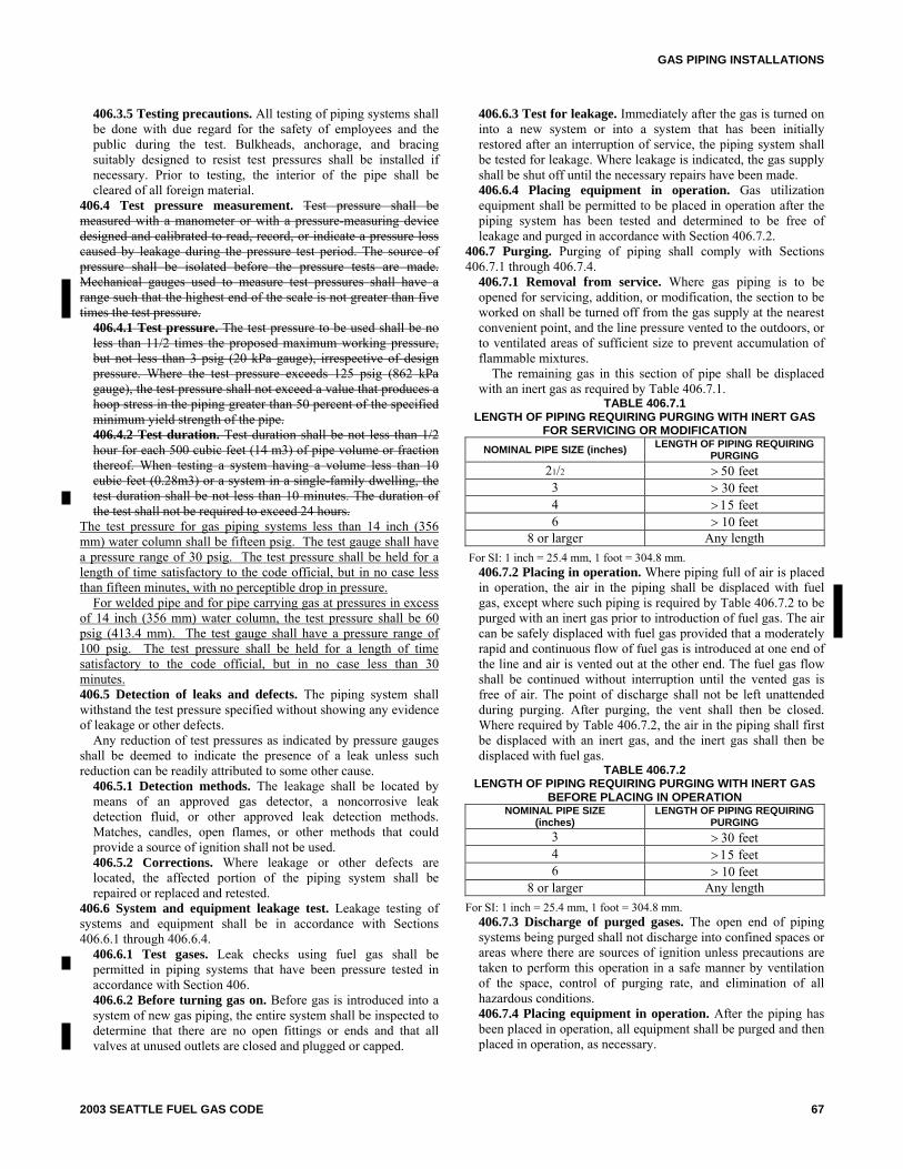
GAS PIPING INSTALLATIONS
406.3.5 Testing precautions. All testing of piping systems shall be done with due regard for the safety of employees and the public during the test. Bulkheads, anchorage, and bracing suitably designed to resist test pressures shall be installed if necessary. Prior to testing, the interior of the pipe shall be cleared of all foreign material.
406.4 Test pressure measurement. Test pressure shall be measured with a manometer or with a pressure-measuring device designed and calibrated to read, record, or indicate a pressure loss caused by leakage during the pressure test period. The source of pressure shall be isolated before the pressure tests are made. Mechanical gauges used to measure test pressures shall have a range such that the highest end of the scale is not greater than five times the test pressure.
406.4.1 Test pressure. The test pressure to be used shall be no less than 11/2 times the proposed maximum working pressure, but not less than 3 psig (20 kPa gauge), irrespective of design pressure. Where the test pressure exceeds 125 psig (862 kPa gauge), the test pressure shall not exceed a value that produces a hoop stress in the piping greater than 50 percent of the specified minimum yield strength of the pipe. 406.4.2 Test duration. Test duration shall be not less than 1/2 hour for each 500 cubic feet (14 m3) of pipe volume or fraction thereof. When testing a system having a volume less than 10 cubic feet (0.28m3) or a system in a single-family dwelling, the test duration shall be not less than 10 minutes. The duration of the test shall not be required to exceed 24 hours.
The test pressure for gas piping systems less than 14 inch (356 mm) water column shall be fifteen psig. The test gauge shall have a pressure range of 30 psig. The test pressure shall be held for a length of time satisfactory to the code official, but in no case less than fifteen minutes, with no perceptible drop in pressure.
For welded pipe and for pipe carrying gas at pressures in excess of 14 inch (356 mm) water column, the test pressure shall be 60 psig (413.4 mm). The test gauge shall have a pressure range of 100 psig. The test pressure shall be held for a length of time satisfactory to the code official, but in no case less than 30 minutes.406.5 Detection of leaks and defects. The piping system shall withstand the test pressure specified without showing any evidence of leakage or other defects.
Any reduction of test pressures as indicated by pressure gauges shall be deemed to indicate the presence of a leak unless such reduction can be readily attributed to some other cause.
406.5.1 Detection methods. The leakage shall be located by means of an approved gas detector, a noncorrosive leak detection fluid, or other approved leak detection methods. Matches, candles, open flames, or other methods that could provide a source of ignition shall not be used. 406.5.2 Corrections. Where leakage or other defects are located, the affected portion of the piping system shall be repaired or replaced and retested.
406.6 System and equipment leakage test. Leakage testing of systems and equipment shall be in accordance with Sections 406.6.1 through 406.6.4.
406.6.1 Test gases. Leak checks using fuel gas shall be permitted in piping systems that have been pressure tested in accordance with Section 406. 406.6.2 Before turning gas on. Before gas is introduced into a system of new gas piping, the entire system shall be inspected to determine that there are no open fittings or ends and that all valves at unused outlets are closed and plugged or capped.
406.6.3 Test for leakage. Immediately after the gas is turned on into a new system or into a system that has been initially restored after an interruption of service, the piping system shall be tested for leakage. Where leakage is indicated, the gas supply shall be shut off until the necessary repairs have been made. 406.6.4 Placing equipment in operation. Gas utilization equipment shall be permitted to be placed in operation after the piping system has been tested and determined to be free of leakage and purged in accordance with Section 406.7.2.
406.7 Purging. Purging of piping shall comply with Sections 406.7.1 through 406.7.4.
406.7.1 Removal from service. Where gas piping is to be opened for servicing, addition, or modification, the section to be worked on shall be turned off from the gas supply at the nearest convenient point, and the line pressure vented to the outdoors, or to ventilated areas of sufficient size to prevent accumulation of flammable mixtures.
The remaining gas in this section of pipe shall be displaced with an inert gas as required by Table 406.7.1.
TABLE 406.7.1 LENGTH OF PIPING REQUIRING PURGING WITH INERT GAS
FOR SERVICING OR MODIFICATION NOMINAL PIPE SIZE (inches) LENGTH OF PIPING REQUIRING
PURGING 21/2 > 50 feet 3 > 30 feet 4 > 15 feet 6 > 10 feet
8 or larger Any length For SI: 1 inch = 25.4 mm, 1 foot = 304.8 mm.
406.7.2 Placing in operation. Where piping full of air is placed in operation, the air in the piping shall be displaced with fuel gas, except where such piping is required by Table 406.7.2 to be purged with an inert gas prior to introduction of fuel gas. The air can be safely displaced with fuel gas provided that a moderately rapid and continuous flow of fuel gas is introduced at one end of the line and air is vented out at the other end. The fuel gas flow shall be continued without interruption until the vented gas is free of air. The point of discharge shall not be left unattended during purging. After purging, the vent shall then be closed. Where required by Table 406.7.2, the air in the piping shall first be displaced with an inert gas, and the inert gas shall then be displaced with fuel gas.
TABLE 406.7.2 LENGTH OF PIPING REQUIRING PURGING WITH INERT GAS
BEFORE PLACING IN OPERATION NOMINAL PIPE SIZE
(inches) LENGTH OF PIPING REQUIRING
PURGING 3 > 30 feet 4 > 15 feet 6 > 10 feet
8 or larger Any length For SI: 1 inch = 25.4 mm, 1 foot = 304.8 mm.
406.7.3 Discharge of purged gases. The open end of piping systems being purged shall not discharge into confined spaces or areas where there are sources of ignition unless precautions are taken to perform this operation in a safe manner by ventilation of the space, control of purging rate, and elimination of all hazardous conditions. 406.7.4 Placing equipment in operation. After the piping has been placed in operation, all equipment shall be purged and then placed in operation, as necessary.
2003 SEATTLE FUEL GAS CODE 67
GAS PIPING INSTALLATIONS
SECTION 407 (IFGC) PIPING SUPPORT
407.1 General. Piping shall be provided with support in accordance with Section 407.2. 407.2 Design and installation. Piping shall be supported with pipe hooks, metal pipe straps, bands, brackets, or hangers suitable for the size of piping, of adequate strength and quality, and located at intervals so as to prevent or damp out excessive vibration. Piping shall be anchored to prevent undue strains on connected equipment and shall not be supported by other piping. Pipe hangers and supports shall conform to the requirements of MSS SP-58 and shall be spaced in accordance with Section 415. Supports, hangers, and anchors shall be installed so as not to interfere with the free expansion and contraction of the piping between anchors. All parts of the supporting equipment shall be designed and installed so they will not be disengaged by movement of the supported piping.
SECTION 408 (IFGC) DRIPS AND SLOPED PIPING
408.1 Slopes. Piping for other than dry gas conditions shall be sloped not less than 1/4 inch in 15 feet (6.3 mm in 4572 mm) to prevent traps. 408.2 Drips. Where wet gas exists, a drip shall be provided at any point in the line of pipe where condensate could collect. A drip shall also be provided at the outlet of the meter and shall be installed so as to constitute a trap wherein an accumulation of condensate will shut off the flow of gas before the condensate will run back into the meter. 408.3 Location of drips. Drips shall be provided with ready access to permit cleaning or emptying. A drip shall not be located where the condensate is subject to freezing. 408.4 Sediment trap. Where a sediment trap is not incorporated as part of the gas utilization equipment, a sediment trap shall be installed downstream of the equipment shutoff valve as close to the inlet of the equipment as practical. The sediment trap shall be either a tee fitting with a capped nipple in the bottom opening of the run of the tee or other device approved as an effective sediment trap. Illuminating appliances, ranges, clothes dryers and outdoor grills need not be so equipped.
SECTION 409 (IFGC) SHUTOFF VALVES
409.1 General. Piping systems shall be provided with shutoff valves in accordance with this section.
409.1.1 Valve approval. Shutoff valves shall be of an approved type. Shutoff valves shall be constructed of materials compatible with the piping. Shutoff valves installed in a portion of a piping system operating above 0.5 psig shall comply with ASME B 16.33. Shutoff valves installed in a portion of a piping system operating at 0.5 psig or less shall comply with ANSI Z 21.15 or ASME B 16.33. 409.1.2 Prohibited locations. Shutoff valves shall be prohibited in concealed locations and furnace plenums. 409.1.3 Access to shutoff valves. Shutoff valves shall be located in places so as to provide access for operation and shall be installed so as to be protected from damage.
409.2 Meter valve. Every meter shall be equipped with a shutoff valve located on the supply side of the meter. 409.3 Shutoff valves for multiple-house line systems. Where a single meter is used to supply gas to more than one building or tenant, a separate shutoff valve shall be provided for each building or tenant.
409.3.1 Multiple tenant buildings. In multiple tenant buildings, where a common piping system is installed to supply other than
one- and two-family dwellings, shutoff valves shall be provided for each tenant. Each tenant shall have access to the shutoff valve serving that tenant’s space. 409.3.2 Individual buildings. In a common system serving more than one building, shutoff valves shall be installed outdoors at each building. 409.3.3 Identification of shutoff valves. Each house line shutoff valve shall be plainly marked with an identification tag attached by the installer so that the piping systems supplied by such valves are readily identified.
409.4 MP Regulator valves. A listed shutoff valve shall be installed immediately ahead of each MP regulator. 409.5 Equipment shutoff valve. Each appliance shall be provided with a shutoff valve separate from the appliance. The shutoff valve shall be located in the same room as the appliance, not further than 6 feet (1829 mm) from the appliance, and shall be installed upstream from the union, connector or quick disconnect device it serves. Such shutoff valves shall be provided with access.
Exception: Shutoff valves for vented decorative appliances and decorative appliances for installation in vented fireplaces shall not be prohibited from being installed in an area remote from the appliance where such valves are provided with ready access. Such valves shall be permanently identified and shall serve no other equipment. Piping from the shutoff valve to within 3 feet (914 mm) of the appliance connection shall be sized in accordance with Section 402. 409.5.1 Shutoff valve in fireplace. Equipment shutoff valves located in the firebox of a fireplace shall be installed in accordance with the appliance manufacturer’s instructions.
SECTION 410 (IFGC) FLOW CONTROLS
410.1 Pressure regulators. A line pressure regulator shall be installed where the appliance is designed to operate at a lower pressure than the supply pressure. Access shall be provided to pressure regulators. Pressure regulators shall be protected from physical damage. Regulators installed on the exterior of the building shall be approved for outdoor installation. 410.2 MP regulators. MP pressure regulators shall comply with the following:
1. The MP regulator shall be approved and shall be suitable for the inlet and outlet gas pressures for the application.
2. The MP regulator shall maintain a reduced outlet pressure under lockup (no-flow) conditions.
3. The capacity of the MP regulator, determined by published ratings of its manufacturer, shall be adequate to supply the appliances served.
4. The MP pressure regulator shall be provided with access. Where located indoors, the regulator shall be vented to the outdoors or shall be equipped with a leak-limiting device, in either case complying with Section 410.3.
5. A tee fitting with one opening capped or plugged shall be installed between the MP regulator and its upstream shutoff valve. Such tee fitting shall be positioned to allow connection of a pressure-measuring instrument and to serve as a sediment trap.
6. A tee fitting with one opening capped or plugged shall be installed not less than 10 pipe diameters downstream of the MP regulator outlet. Such tee fitting shall be positioned to allow connection of a pressure-measuring instrument.
410.3 Venting of regulators. Pressure regulators that require a vent shall have an independent vent to the outside of the building.
68 2003 SEATTLE FUEL GAS CODE

GAS PIPING INSTALLATIONS
The vent shall be designed to prevent the entry of water or foreign objects.
Exception: A vent to the outside of the building is not required for regulators equipped with and labeled for utilization with approved vent-limiting devices installed in accordance with the manufacturer’s instructions. Regulators equipped with limiting orifices capable of releasing not more than 5 cubic feet of gas per hour (0.04 L/sec), when supplied with medium pressure, need not be vented to an outside location when the regulators have been approved by the code official. The regulators shall:
1. Have an approved gas valve in the line upstream of the regulator;
2. Be accessible; 3. Have upstream pressure identified by a metal tag
permanently attached to the regulator that states: “WARNING 1/2 to 5 pounds (3.4- 34.5 kPa) natural gas pressure. DO NOT REMOVE”; and
4. Be in an area approved by the code official that communicates with a naturally ventilated area.
SECTION 411 (IFGC) APPLIANCE CONNECTIONS
411.1 Connecting appliances. Appliances shall be connected to the piping system by one of the following:
1. Rigid metallic pipe and fittings. 2. Semirigid metallic tubing and metallic fittings. Lengths shall
not exceed 6 feet (1829 mm) and shall be located entirely in the same room as the appliance. Semirigid metallic tubing shall not enter a motor-operated appliance through an unprotected knockout opening.
3. Listed and labeled appliance connectors installed in accordance with the manufacturer’s installation instructions and located entirely in the same room as the appliance.
4. Listed and labeled quick-disconnect devices used in conjunction with listed and labeled appliance connectors.
5. Listed and labeled convenience outlets used in conjunction with listed and labeled appliance connectors.
6. Listed and labeled appliance connectors complying with ANSI Z21.69 and listed for use with food service equipment having casters, or that is otherwise subject to movement for cleaning, and other large movable equipment.
411.1.1 Protection from damage. Connectors and tubing shall be installed so as to be protected against physical damage. 411.1.2 Appliance fuel connectors. Connectors shall have an overall length not to exceed 3 feet (914 mm), except for range and domestic clothes dryer connectors, which shall not exceed 6 feet (1829 mm) in length. Connectors shall not be concealed within, or extended through, walls, floors, partitions, ceilings or appliance housings. A shutoff valve not less than the nominal size of the connector shall be installed ahead of the connector in accordance with Section 409.5. Connectors shall be sized to provide the total demand of the connected appliance.
Exception: Fireplace inserts factory equipped with grommets, sleeves, or other means of protection in accordance with the listing of the appliance. Note: This exception applies to grommets that are included in the listing of the appliance.
411.1.3 Movable appliances. Where appliances are equipped with casters or are otherwise subject to periodic movement or relocation for purposes such as routine cleaning and maintenance, such appliances shall be connected to the supply system piping by means of an approved flexible connector
designed and labeled for the application. Such flexible connectors shall be installed and protected against physical damage in accordance with the manufacturer’s installation instructions.
SECTION 412 (IFGC) LIQUEFIED PETROLEUM GAS MOTOR VEHICLE FUEL-
DISPENSING STATIONS 412.1 General. Motor fuel-dispensing facilities for LP-gas fuel shall be in accordance with this section and the International Fire Code. The operation of LP-gas motor fuel-dispensing facilities shall be regulated by the International Fire Code. 412.2 Storage and dispensing. Storage vessels and equipment used for the storage or dispensing of LP-gas shall be approved or listed in accordance with Sections 412.3 and 412.4. 412.3 Approved equipment. Containers; pressure-relief devices, including pressure-relief valves; and pressure regulators and piping used for LP-gas shall be approved. 412.4 Listed equipment. Hoses, hose connections, vehicle fuel connections, dispensers, LP-gas pumps and electrical equipment used for LP-gas shall be listed. 412.5 Attendants. Motor vehicle fueling operations shall be conducted by qualified attendants or in accordance with Section 412.8 by persons trained in the proper handling of LP-gas. 412.6 Location. In addition to the fuel dispensing requirements of the International Fire Code, the point of transfer for dispensing operations shall be 25 feet (7620 mm) or more from buildings having combustible exterior wall surfaces, buildings having noncombustible exterior wall surfaces that are not part of a 1-hour fire-resistance-rated assembly or buildings having combustible overhangs, property which could be built on public streets, or sidewalks and railroads; and at least 10 feet (3048 mm) from driveways and buildings having noncombustible exterior wall surfaces that are part of a fire-resistance-rated assembly having a rating of 1 hour or more.
Exception: The point of transfer for dispensing operations need not be separated from canopies providing weather protection for the dispensing equipment constructed in accordance with the International Building Code. Liquefied petroleum gas containers shall be located in
accordance with the International Fire Code. Liquefied petroleum gas storage and dispensing equipment shall be located outdoors and in accordance with the International Fire Code. 412.7 Installation of dispensing devices and equipment. The installation and operation of LP-gas dispensing systems shall be in accordance with this section and the International Fire Code. Liquefied petroleum gas dispensers and dispensing stations shall be installed in accordance with manufacturers’ specifications and their listing.
412.7.1 Valves. A manual shutoff valve and an excess flow-control check valve shall be located in the liquid line between the pump and the dispenser inlet where the dispensing device is installed at a remote location and is not part of a complete storage and dispensing unit mounted on a common base.
An excess flow-control check valve or an emergency shutoff valve shall be installed in or on the dispenser at the point at which the dispenser hose is connected to the liquid piping. A differential backpressure valve shall be considered equivalent protection. A listed shutoff valve shall be located at the discharge end of the transfer hose. 412.7.2 Hoses. Hoses and piping for the dispensing of LP-gas shall be provided with hydrostatic relief valves. The hose length
2003 SEATTLE FUEL GAS CODE 69

GAS PIPING INSTALLATIONS
shall not exceed 18 feet (5486 mm). An approved method shall be provided to protect the hose against mechanical damage. 412.7.3 Vehicle impact protection. Vehicle impact protection for LP-gas storage containers, pumps and dispensers shall be provided in accordance with the International Fire Code.
412.8 Private fueling of motor vehicles. Self-service LP-gas dispensing systems, including key, code and card lock dispensing systems, shall not be open to the public and shall be limited to the filling of permanently mounted fuel containers on LP-gas powered vehicles. In addition to the requirements in the International Fire Code, self-service LP-gas dispensing systems shall be provided with an emergency shutoff switch located within 100 feet (30 480 mm) of, but not less than 20 feet (6096 mm) from, dispensers and the owner of the dispensing facility shall ensure the safe operation of the system and the training of users.
SECTION 413 (IFGC) COMPRESSED NATURAL GAS MOTOR VEHICLE FUEL-
DISPENSING STATIONS 413.1 General. Motor fuel-dispensing facilities for CNG fuel shall be in accordance with this section and the International Fire Code. The operation of CNG motor fuel-dispensing facilities shall be regulated by the International Fire Code. 413.2 General. Storage vessels and equipment used for the storage, compression or dispensing of CNG shall be approved or listed in accordance with Sections 413.2.1 and 413.2.2.
413.2.1 Approved equipment. Containers; compressors; pressure-relief devices, including pressure-relief valves; and pressure regulators and piping used for CNG shall be approved. 413.2.2 Listed equipment. Hoses, hose connections, dispensers, gas detection systems and electrical equipment used for CNG shall be listed. Vehicle fueling connections shall be listed and labeled.
413.3 Location of dispensing operations and equipment. Compression, storage and dispensing equipment shall be located above ground outside.
Exceptions: 1. Compression, storage or dispensing equipment is allowed
in buildings of noncombustible construction, as set forth in the International Building Code, which are unenclosed for three-quarters or more of the perimeter.
2. Compression, storage and dispensing equipment is allowed to be located indoors in accordance with the International Fire Code.
413.3.1 Location on property. In addition to the fuel-dispensing requirements of the International Fire Code, compression, storage and dispensing equipment shall not be installed:
1. Beneath power lines, 2. Less than 10 feet (3048 mm) from the nearest building or
property line which could be built on, public street, sidewalk, or source of ignition.
Exception: Dispensing equipment need not be separated from canopies providing weather protection for the dispensing equipment constructed in accordance with the International Building Code.
3. Less than 25 feet (7620 mm) from the nearest rail of any railroad track.
4. Less than 50 feet (15 240 mm) from the nearest rail of any railroad main track or any railroad or transit line where power for train propulsion is provided by an outside electrical source such as third rail or overhead catenary.
5. Less than 50 feet (15 240 mm) from the vertical plane below the nearest overhead wire of a trolley bus line.
413.4 Private fueling of motor vehicles. Self-service CNG-dispensing systems, including key, code and card lock dispensing systems, shall be limited to the filling of permanently mounted fuel containers on CNG-powered vehicles.
In addition to the requirements in the International Fire Code, the owner of a self-service CNG-dispensing facility shall ensure the safe operation of the system and the training of users. 413.5 Pressure regulators. Pressure regulators shall be designed, installed or protected so their operation will not be affected by the elements (freezing rain, sleet, snow, ice, mud or debris). This protection is allowed to be integral with the regulator. 413.6 Valves. Piping to equipment shall be provided with a manual shutoff valve. Such valve shall be provided with ready access. 413.7 Emergency shutdown equipment. An emergency shutdown device shall be located within 75 feet (22 860 mm) of, but not less than 25 feet (7620 mm) from, dispensers and shall also be provided in the compressor area. Upon activation, the emergency shutdown shall automatically shut off the power supply to the compressor and close valves between the main gas supply and the compressor and between the storage containers and dispensers. 413.8 Discharge of CNG from motor vehicle fuel storage containers. The discharge of CNG from motor vehicle fuel cylinders for the purposes of maintenance, cylinder certification, calibration of dispensers or other activities shall be in accordance with this section. The discharge of CNG from motor vehicle fuel cylinders shall be accomplished through a closed transfer system or an approved method of atmospheric venting in accordance with Section 413.8.1 or 413.8.2.
413.8.1 Closed transfer system. A documented procedure which explains the logical sequence for discharging the cylinder shall be provided to the code official for review and approval. The procedure shall include what actions the operator will take in the event of a low-pressure or high-pressure natural gas release during the discharging activity. A drawing illustrating the arrangement of piping, regulators and equipment settings shall be provided to the code official for review and approval. The drawing shall illustrate the piping and regulator arrangement and shall be shown in spatial relation to the location of the compressor, storage vessels and emergency shutdown devices. 413.8.2 Atmospheric venting. Atmospheric venting of motor vehicle fuel cylinders shall be in accordance with Sections 413.8.2.1 through 413.8.2.6.
413.8.2.1 Plans and specifications. A drawing illustrating the location of the vessel support, piping, the method of grounding and bonding, and other requirements specified herein shall be provided to the code official for review and approval. 413.8.2.2 Cylinder stability. A method of rigidly supporting the vessel during the venting of CNG shall be provided. The selected method shall provide not less than two points of support and shall prevent the horizontal and lateral movement of the vessel. The system shall be designed to prevent the movement of the vessel based on the highest gas-release velocity through valve orifices at the vessel’s rated pressure and volume. The structure or appurtenance shall be constructed of noncombustible materials. 413.8.2.3 Separation. The structure or appurtenance used for stabilizing the cylinder shall be separated from the site
70 2003 SEATTLE FUEL GAS CODE
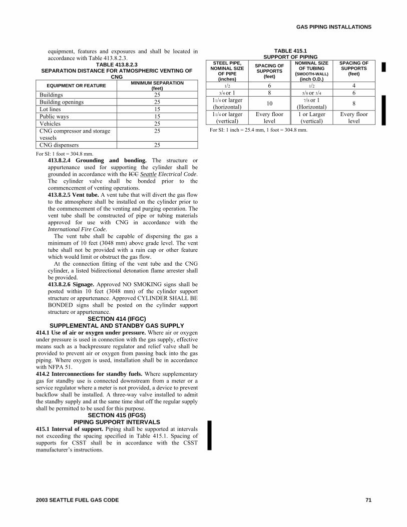
GAS PIPING INSTALLATIONS
equipment, features and exposures and shall be located in accordance with Table 413.8.2.3.
TABLE 413.8.2.3 SEPARATION DISTANCE FOR ATMOSPHERIC VENTING OF
CNG EQUIPMENT OR FEATURE MINIMUM SEPARATION
(feet) Buildings 25 Building openings 25 Lot lines 15 Public ways 15 Vehicles 25 CNG compressor and storage vessels
25
CNG dispensers 25 For SI: 1 foot = 304.8 mm.
413.8.2.4 Grounding and bonding. The structure or appurtenance used for supporting the cylinder shall be grounded in accordance with the ICC Seattle Electrical Code. The cylinder valve shall be bonded prior to the commencement of venting operations. 413.8.2.5 Vent tube. A vent tube that will divert the gas flow to the atmosphere shall be installed on the cylinder prior to the commencement of the venting and purging operation. The vent tube shall be constructed of pipe or tubing materials approved for use with CNG in accordance with the International Fire Code.
The vent tube shall be capable of dispersing the gas a minimum of 10 feet (3048 mm) above grade level. The vent tube shall not be provided with a rain cap or other feature which would limit or obstruct the gas flow.
At the connection fitting of the vent tube and the CNG cylinder, a listed bidirectional detonation flame arrester shall be provided. 413.8.2.6 Signage. Approved NO SMOKING signs shall be posted within 10 feet (3048 mm) of the cylinder support structure or appurtenance. Approved CYLINDER SHALL BE BONDED signs shall be posted on the cylinder support structure or appurtenance.
SECTION 414 (IFGC) SUPPLEMENTAL AND STANDBY GAS SUPPLY
414.1 Use of air or oxygen under pressure. Where air or oxygen under pressure is used in connection with the gas supply, effective means such as a backpressure regulator and relief valve shall be provided to prevent air or oxygen from passing back into the gas piping. Where oxygen is used, installation shall be in accordance with NFPA 51. 414.2 Interconnections for standby fuels. Where supplementary gas for standby use is connected downstream from a meter or a service regulator where a meter is not provided, a device to prevent backflow shall be installed. A three-way valve installed to admit the standby supply and at the same time shut off the regular supply shall be permitted to be used for this purpose.
SECTION 415 (IFGS) PIPING SUPPORT INTERVALS
415.1 Interval of support. Piping shall be supported at intervals not exceeding the spacing specified in Table 415.1. Spacing of supports for CSST shall be in accordance with the CSST manufacturer’s instructions.
TABLE 415.1 SUPPORT OF PIPING
STEEL PIPE, NOMINAL SIZE
OF PIPE (inches)
SPACING OF SUPPORTS
(feet)
NOMINAL SIZE OF TUBING
(SMOOTH-WALL)(inch O.D.)
SPACING OF SUPPORTS
(feet)
1/2 6 1/2 4 3/4 or 1 8 5/8 or 3/4 6
11/4 or larger(horizontal)
10 7/8 or 1 (Horizontal)
8
11/4 or larger(vertical)
Every floor level
1 or Larger (vertical)
Every floor level
For SI: 1 inch = 25.4 mm, 1 foot = 304.8 mm.
2003 SEATTLE FUEL GAS CODE 71

GAS PIPING INSTALLATIONS
72 2003 SEATTLE FUEL GAS CODE