Embed Size (px)
Citation preview
Nov. 25, 1941. W. H. FRANK 2,264,075 ELECTRICAL DISTRIBUTION SYSTEM
Filled Feb. 23, 1940 5. Sheets-Sheet l
. INVENTOR.
is ? BY all &/
ATTORNEY.
Nov. 25, 1941. W. H. FRANK 2,264,075 ELECTRICAL DISTRIBUTION SYSTEM
Filed Feb. 23, 1940 5 Sheets-Sheet 2
Leer-rrrrrrrrrrierrerraraz
ATTORNEY.
INVENTOR.
BY %it... %a-c-3/
Nov. 25, 1941. W. H. FRANK 2,264,075 ELECTRICAL DISTRIBUTION SYSTEM
Filed Feb. 23, 1940 5 Sheets-Sheet 3
//
asbestos - Z-f F/AAR
3 a. N
. 2 s 27 &
BY A. ATTORNEY.
Nov. 25, 1941. W. H. FRANK 2,264,075 ELECTRICAL DISTRIBUTION SYSTEM
Filed Feb. 23, 1940 5 Sheets-Sheet 4
is - 7-2-15 /7
- - - -
- - - - - -lt-le-le. Re - - - - - - - -
3
- Z-27-17 INVENTOR.
Nov. 25, 1941. W. H. FRANK 2,264,075 ELECTRICAL DISTRIBUTION SYSTEM
Filed Feb. 23, 1940 5. Sheets-Sheet 5
N N: Š NY &S. - 727 2 as
INVENTOR.
BY
ATTORNEY
Patented Nov. 25, 1941 2,264,075 UNITED STATES PATENT OFFICE
2,264,075 ELECTRICAL DISTRIBUTION SYSTEM
William H. Frank, Detroit, Mich., assignor to Bulldog Electric Products Company, Detroit, Mich., a corporation of West Virginia
Application February 23, 1940, Serial No. 320,454 (C. 173-334.1) 2 Clains.
This application relates to electrical distribu tion systems of the bus duct type as shown in a prior application, Serial No. 231,712, of Sep tember 26, 1938, now abandoned. Bus duct systems have been known before.
For example, Patent No. 2,041,675 of May 19, 1936, discloses a bus duct system. This applica tion relates specifically to an improved bus duct System. W
The system of this application is simple in form, inexpensive to manufacture, easy to take apart for replacement or repair of any part that might prove to be defective and contains many novel features, The system hereof is so constructed that it
effectively solves a serious problem found in the use of bus duct systems, namely the problem of destruction due to power arcs which start in the space between the bus bars and the metal duct commonly used. A bus duct system employs branch circuit
takeoff devices, commonly known as plugs, hav ing prongs for engaging the bus bars despite that the prongs directly engage and make contact with the bus bars. I am able to insulate the bus bars on their outside surfaces, even at prong engaged points. This is because the System is such that contact between the plug prongs and the bus bars is made, not on the outside of the bus bars, as is conventional, but on the insides of the bus bars, these being made hollow for this purpose. In this way, the bus bars may be insulated on their outside throughout their entire length. Consequently, power arcs will not arise, because these arcs arise only at uninsulated points of the bus bars. In the system hereof novel splices are provided
for the bus bar ends, and these Splices are So designed that they permit the bus bars to be insulated on their outsides continuously, even at the splices. A feature of the system hereof is the novel
arrangement for providing insulated openings through which plug prongs are inserted. At such openings there is provided a hollow insula tor through which the bus bar passes and having an opening or well through which the plug prong passes, the opening being sealed from the inside of the duct except where it intercepts the opening through which the bus bar passes.
In this way, a prong inserted into the duct through the prong opening of the insulator is sealed from the inside of the duct. The insula tor is longitudinally movable so that part thereof may be used as a shutter for the duct opening, if desired. Another feature is a novel construction of
the plug prong, constructed to provide a lateral resilient contact pressure on the bus bar. Another feature is a novel arrangement for
5
O
15
20
25
30
35
40
5 5
60
drawingS.
mounting insulators in the duct using shock absorbing material between the duct wall and the insulator. The system hereof is shown in the appended
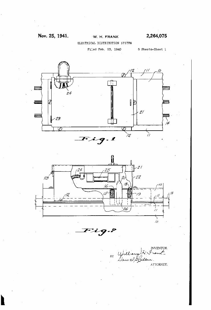
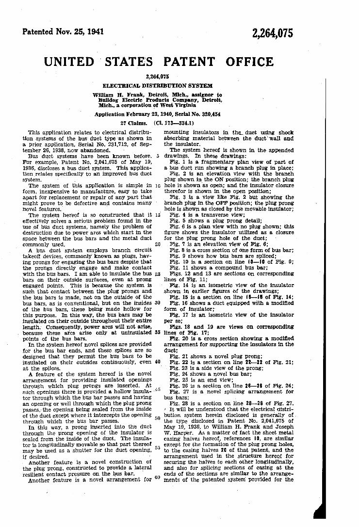
In these drawings: Fig. 1 is a fragmentary plan view of part of
a bus duct run showing a branch plug in place; Fig. 2 is an elevation view with the branch
plug shown in the ON position; the branch plug hole is shown as Open; and the insulator closure therefor is shown in the open position;
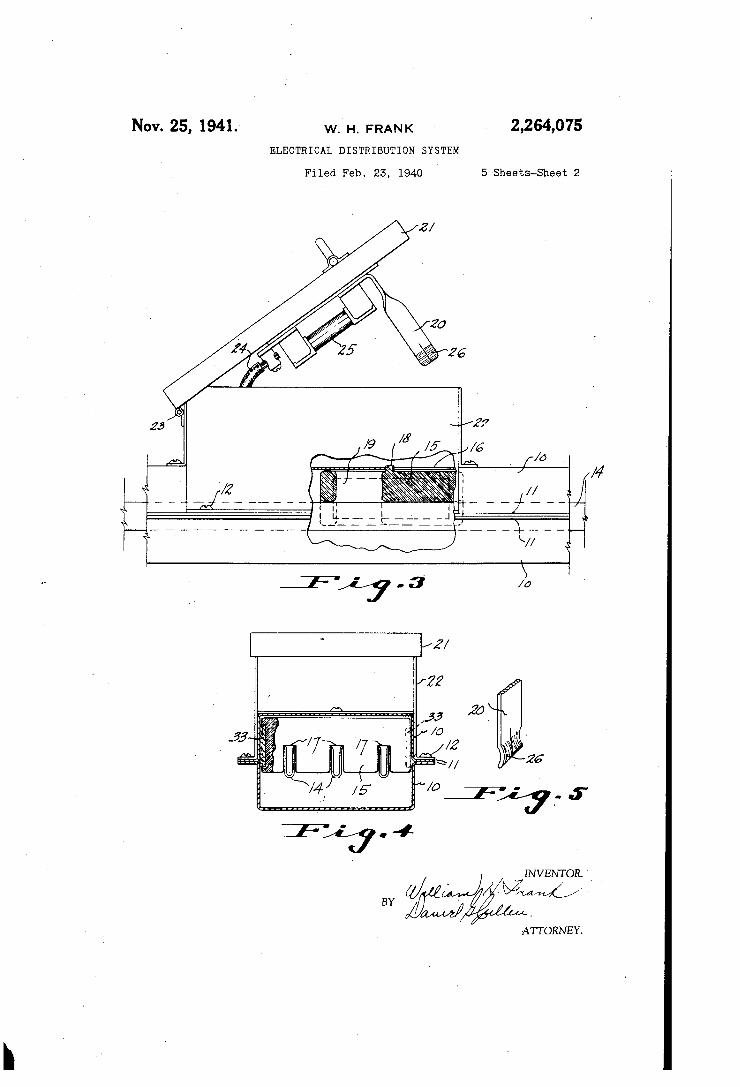
Fig. 3 is a view like Fig. 2 but showing the branch plug in the OFF position; the plug prong hole is shown as closed by the movable insulator;
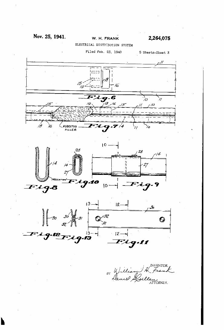
Fig. 4 is a transverse view; Fig. 5 shows a plug prong detail; Fig. 6 is a plan view with no plug shown; this
figure shows the insulator utilized as a closure for the plug prong hole of the duct;
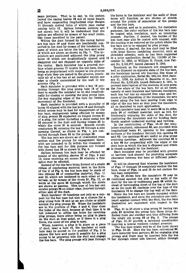
Fig. 7 is an elevation view of Fig. 6; Fig. 8 is a cross section of One form of bus bar; Fig. 9 shows how bus bars are spliced; Fig. 10 is a section on line O-O of Fig. 9; Fig. 11 shows a compound bus bar; Figs. 12 and 13 are Sections on corresponding
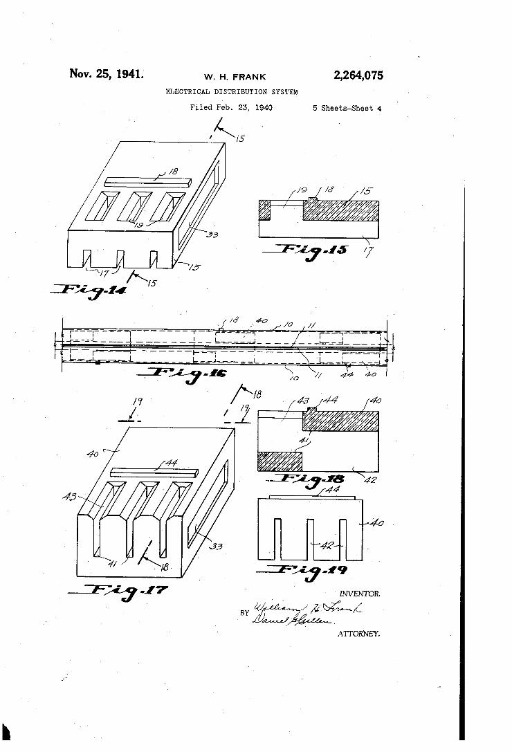
lines of Fig. 11; Fig. 4 is an isometric view of the insulator
shown in earlier figures of the drawings; Fig. 15 is a section on line 5-5 of Fig. 14; Fig. 16 shows a duct equipped with a modified
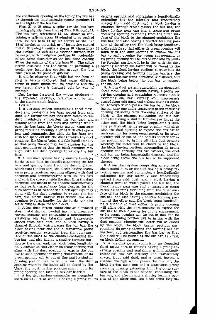
form of insulator; Fig. 17 is an isometric view of the insulator
per Se; Figs. 18 and 19 are views on corresponding
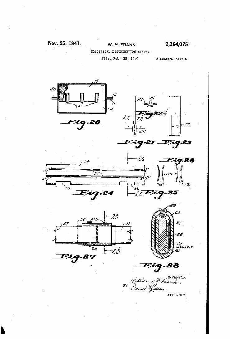
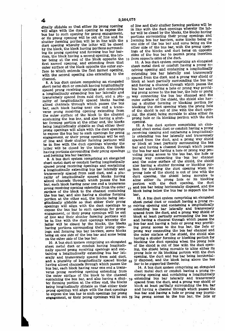
lines of Fig. 17; Fig. 20 is a cross section showing a modified
arrangement for supporting the insulators in the duct;
Fig. 21 shows a novel plug prong; Fig. 22 is a section on line 22-22 of Fig. 21; Fig. 23 is a side view of the prong; Fig. 24 shows a novel bus bar; Fig. 25 is an end view; Fig. 26 is a section on line 26-26 of Fig. 24;
. 27 is a novel splicing arrangement for bus bars;
Fig. 28 is a section on line 28-28 of Fig. 27. It will be understood that the electrical distri
bution system herein disclosed is generally of the type disclosed in Patent No. 2,041,675 of May 19, 1936, to William H. Frank and Joseph W. Harper. As a matter of fact the sheet metal casing halves hereof, references fo, are similar except for the formation of the plug prong holes, to the casing halves 20 of that patent, and the arrangement used in the structure hereof for securing the halves to each other longitudinally, and also for splicing sections of Casing at the ends of the sections are similar to the arrange ments of the patented system provided for the
2 Same purpose. That is to say, in the System Jhereof the casing halves. O are of equal length and have cooperating longitudinal edge flanges
through slotted holes of which pass casing joining bolts 2. Splices between sections are not shown but it will be understood that the Splices are effected by means of lap scarf joints, like those described in the patent. Within the duct formed by the casing halves
are bus bars 4 and these are insulatedly sup ported in the duct by means of the insulators 5, Some of which are below the bus bars and some of which are above, as shown in Fig. 7. The in Sulators are positioned adjacent the plug prong holes 6 which are longitudinally spaced and staggered and are disposed on opposite sides of the casing. Each insulator has a grooved sur face whose grooves 7 receive the bus bars, these being so proportioned with respect to the grooves that when they are seated in the grooves, practi cally all of a bus bar at an insulator except one edge is closely surrounded by the wall of the grooves (Fig. 4). Each insulator is provided with a key 18 pro
jecting through the plug prong hole 6 of the duct to enable the insulator to be slid longitudi rially for closing or opening the plug prong hole, the key engaging edges of the hole for limiting movement of the insulator.
Each insulator is provided with a plurality of bores 9 aligned with the bus bars 4 and through which access may be had for engagement of the bus bars, engagement being effected by means of plug prongs 20 supported on hinged covers 2 of a plug, the latter including a sheet metal box 22 secured to the duct and having hinges 23 to which the cover 2 is secured. Branch circuit conductors 24, entering the box 22 through a side Opening thereof, as shown in Fig. 1, are Con nected through fuses 25 to the prongs 20. The bus bars are shown as of channelled cross
section and the prongs for engagement there with are intended to fit within the channels of the bus bars and for this purpose are formed with flared tips 26 as shown in Fig. 5.
Splices between bus bars may be effected by means of the splicing sleeves 27 of FigS. 9 and 10, these receiving set screws 28 whereby a firm splice may be effected.
Instead of the bus bars being formed of a single ribbon of conducting material bent in the form of the U of Fig. 8, the bus bars may be made of two ribbons 30 of conducting material, Figs. 11 and 12, which are buttoned to each other at in tervals, as by means of the rivets 3, Fig. 13, or welds at the spots 32 through which the rivets are shown as passing. This type of bus bar can receive prongs 20 on either edge, inserted through either side of the duct.
Each insulator 5 functions not only as a Sup port for the bus bars but also as a closure for a plug prong hole 6 and as an arc chute or shield around the plug prongs 20. When the insulators are in the position of Figs. 3 and 6, they close the holes of the duct, because at that time it is not intended to utilize the holes for receiving plug prongs, there either being no plug in place
5
10
15
20
25
30
35
2,264,075 the bores in the insulator and the walls of these bores will function as arc chutes or shields around the points of separation of the prongs and the bus bars.
if desired, and as is preferable, for insulation purposes, the outer surface of the bus bars may be coated with insulation, such as insulating enamel. Further, if desired, the insides of the bus bars may also be coated with enamel, with the coating to be removed at the points where the bus bars are to be engaged by plug prongs.
Further, if desired, the bus duct may be filled with loose fibrous insulating material, such as shredded asbestos, such as has been suggested in a prior application, Serial No. 116,985 of De cember 21, 1936, of William H. Frank, now Pat ent No. 2,186,377, issued January 9, 1940.
Inasmuch as the insulators are staggered as well as disposed on opposite sides of the bus bars, the insulators hereof will function like those of a prior application, Serial No. 183,144, filed Janu ary 31, 1938, by Arthur S. Bassette et al., now Patent No. 2,230,423, issued February 4, 1941, to prevent interruption of the coursing of arcs along the free edges of the bus bars, for at all times, namely at each insulator and between insulators, each bus bar has an exposed free edge and be cause of the disposition of the insulators, the arcs travel along the bus bars moving from edge to edge of the bus bars as they pass the insulators, all as described in such application.
Each insulator may seat in seats 33 in its sides, pads 34 of resilient material, such as felt, for frictionally engaging the sides of the duct, for cushioning the insulators and for holding them firmly against undesired moving and rattling. In the construction of Figs. 16-19 the insu
lators employed, referenced 40, are provided with longitudinal bores 4, opening to the opposite
40
50 .
55
60
65
on the duct at that point, or if there is a plug there, the cover of the plug is Open. When, however, a plug is in place on a piece
of duct, near a hole f6, the insulator at such hole may be moved to the position of Fig. 2 to expose the hole and make it possible for a plug prong to be projected into the duct and engage the bus bars. The plug prongs will pass through
70
surfaces of the insulator through the opening 42 and 43; the openings 43 are useful as plug prong receiving openings. Adjacent the openings, 43 is a key 44 for cooperating with the edges of the duct hole in which the key is disposed and which is closed normally by the insulator.
Each insulator may be provided with grooves or barriers (not shown) for providing adequate clearance between bus bars or different polari ties.
It will be observed that whereas the insulators of Figs. 17 through 19 completely enclose the bus bars, those of Figs. 14 and 15 do not enclose the bus bars completely.
Fig. 20 shows how the insulators 5 may be cushioned against the side or top walls of the duct by the use of cushioning pads 50 which in stead of terminating short of the top of the duct as do the pads 33, continue over the tops of the insulators 5 to engage the top wall of the duct. Since the bus bars are loosely mounted within
the insulators, and since the insulators are cush ioned against contact with the duct, the bus bars themselves are cushioned with respect to the duct.
Figs. 21 to 23 show a plug prong 5 having two slots 52 dividing the prong into three strips de flected from one another and thus differing from the singly slit prong 20 of Fig. 3. The prongs of Figs. 21-23 provide a balanced construction insuring a lateral resilient contact pressure. The bus bars might well be of the form shown
in Figs. 24-26. Here the bus bars, referenced 54, have inwardly bent portions 55 for engaging plug
75 prongs and these may be inserted into the bus bar through either side thereof, either through
2,264,075 the continuous opening at the top of the bus bar or through the longitudinally spaced Openings 56 in the bight of the bus bar.
Figs. 27 to 28 show a splice for the bus bars differing slightly from that of Figs. 9 through 11. The bus bars, referenced 57, are shown as con taining a splicing strap 58 adapted to be wedged into the bus bars 57 by set screws or the like 59 of insulation material, or of insulation capped metal, threaded through a sleeve 60 whose inte rior surface, as well as its exterior Surface, may be coated with insulation coatings 6, preferably of the same character as the insulation coating 62 on the outside of the bus bars 57. The splice herein disclosed has the virtue of providing a continuous insulation coating around the bus runs even at the point of Splicing.
It will be observed that while but one form of plug is herein disclosed, that many different forms of plugs might well be provided and the one herein shown is disclosed only by way of example. Now having described the System disclosed in
the appended drawings, reference will be had to the claims which follow. I claim: 1. A bus duct System comprising a sheet metal
duct and containing bus bars spaced from said duct and having unitary insulator blocks in the duct insulatedly supporting the bus bars and : Spacing them from the duct and through which paSS the bus bars, the blocks having transverse prong receiving openings aligned with duct open ings and communicating with the bus bars and With the Space outside the duct through the duct Openings, the blocks being slidable longitudinally So that parts thereof may form closures for the duct openings or So that the block openings may align With the duct openings to expose the bus bars.
2. A bus duct System having unitary insulator blocks in the duct insulatedly supporting the bus bars and spacing them from the duct and thru which pass the bus bars, the blocks having trans Verse prong receiving openings aligned with duct openings and communicating with the bus bars and with the Space outside the duct thru the duct openings, the blocks being slidable longitudinally so that parts thereof may form closures for the duct openings or So that the block openings may align. With the duct openings to expose the bus bars, the blocks having keys within the duct openings to form handles for the blocks and also for Serving as stops for the blocks.
3. A bus duct System comprising an elongated sheet metal duct or conduit having a prong re ceiving opening and containing a longitudinally, extending bus bar laterally and transversely spaced from Said duct, and a block having a channel through which passes the bus bar, the block having near One end a transverse prong receiving opening extending from the outer Sur face of the block to the channel containing the bus bar, and also having a shutter forming por tion at the other end, the block being longitudi nally slidable so that either its prong opening Will align with the duct opening to expose the bus bar to such opening for prong engagement, or its prong opening Will be out of line and its shutter forming portion Will be in line With the duct opening whereby the latter will be closed by the block, the block having portions surrounding its prong opening and forming bus bar barriers.
4. A bus duct System comprising an elongated sheet metal duct or conduit having a prong re
20
20
40
50
55
60
65
70
75
3 ceiving opening and containing a longitudinally extending bus bar laterally and transversely Spaced from said duct, and a block having a channel through which passes the bus bar, the block having near one end a transverse prong receiving Opening extending from the outer Sur face of the block to the channel containing the bus bar, and also having a shutter forming por tion at the other end, the block being longitudi nally slidable so that either its prong opening will align with the duct opening to expose the bus bar to Such opening for prong engagement, or its prong Opening Will be out of line and its shut ter forming portion Will be in line with the duct opening whereby the latter will be closed by the block, the block having portions surrounding its prong opening and forming bus bar barriers, the duct and bus bar being horizontally disposed, and the block being below the bus bar to support the bus bar.
5. A bus duct System comprising an elongated sheet metal duct or conduit having a prong re ceiving Opening and containing a longitudinally extending bus bar laterally and transversely Spaced from said duct, and a block having a chan nel through which passes the bus bar, the block having near one end a transverse prong receiving opening extending from the outer surface of the block to the channel containing the bus bar, and also having a shutter forming portion at the other end, the block being longitudinally slid able so that either its prong opening will align With the duct opening to expose the bus bar to Such opening for prong engagement, or its prong opening Will be out of line and its shutter form ing portion will be in line with the duct opening whereby the latter will be closed by the block, the block having portions surrounding its prong Opening and forming bus bar barriers, the duct and bus bar being horizontally disposed, and the block being above the bus bar to be supported thereby.
6. A bus duct System comprising an elongated sheet metal duct or conduit having a prong re ceiving Opening and containing a longitudinally extending bus bar laterally and transversely Spaced from Said duct, and a block having a channel through which passes the bus bar, the block having near one end a transverse prong receiving Opening extending from the outer sur face of the block to the channel containing the bus bar, and also having a shutter forming por tion at the other end, the block being longitudi nally slidable so that either its prong opening Will align with the duct opening to expose the bus bar to such opening for prong engagement, or its prong opening will be out of line and its shutter forming portion will be in line with the duct opening whereby the latter will be closed by the block, the block having portions sur rounding its prong Opening and forming bus bar barriers, and surrounding the bus bar so that the block will be guided by the bus bar, as a rail, On block sliding movement.
7. A bus duct System comprising an elongated sheet metal duct or conduit having a prong re ceiving opening and containing a longitudinally extending bus bar laterally and transversely Spaced from Said duct, and a block having a channel through which passes the bus bar, the block having near one end a transverse prong receiving opening extending from the outer Sur face of the block to the channel containing the bus bar, and also having a shutter forming por tion at the other end, the block being longitu
4. dinally slidable so that either its prong opening will align with the duct opening to expose the bus bar to such opening for prong engagement, or its prong opening will be out of line and its shutter forming portion will be in line with the duct opening whereby the latter will be closed by the block, the block having portions surround ing its prong opening and forming bus bar bar riers, the block having a second opening, the lat ter being at the end of the block opposite the first named opening, and extending from that outer surface of the block opposite the Outer Sur face to which extends the first named opening, with the second opening also, extending to the channel.
8. A bus duct system comprising an elongated sheet metal duct or conduit having longitudinally spaced prong receiving openings and containing a longitudinally extending bus bar laterally and transversely spaced from said duct, and a plu rality of longitudinally spaced blocks having alined channels through which passes the bus bar, each block having near one end a trans verse prong receiving opening extending from the outer surface of the block to the channel containing the bus bar, and also having a shut ter forming portion at the other end, the blocks being longitudinally slidable so that either their prong openings will align with the duct openings to expose the bus bar to such openings for prong engagement, or their prong openings will be out of line and their shutter forming portions will be in line with the duct openings whereby the latter will be closed by the blocks, the blocks having portions surrounding their prong openings and forming bus bar barriers.
9. A bus duct system comprising an elongated sheet metal duct or conduit having longitudinally spaced prong receiving openings and containing a longitudinally extending bus bar laterally and transversely spaced from Said duct, and a plu rality of longitudinally spaced blocks having alined channels through which passes the bus bar, each block having near One end a transverse prong receiving opening extending from the Outer surface of the block to the channel containing the bus bar, and also having a shutter forming portion at the other end, the blocks being lon gitudinally slidable so that either their prong openings will align with the duct openings to expose the bus bar to such openings for prong engagement, or their prong openings will be out of line and their shutter forming portions will be in line with the duct openings whereby the latter will be closed by the blocks, the blocks having portions surrounding their prong open ings and forming bus bar barriers, some blocks being on one side of the bus bar and some being on the other side of the bus bar.
10. A bus duct System comprising an elongated sheet metal duct or conduit having longitudi nally spaced prong receiving openings and con taining a longitudinally extending bus bar lat erally and transversely spaced from said duct, and a plurality of longitudinally spaced blocks having allined channels through which passes the bus bar, each block having near one end a trans verse prong receiving opening extending from the outer surface of the block to the channel Containing the bus bar, and also having a shut ter forming portion at the other end, the blocks being longitudinally slidable so that either their prong openings will align with the duct openings to expose the bus bar to Such openings for prong engagement, or their prong openings will be out
()
2 5
30
3 s
40
55
60
65
70
75
2,264,075 of line and their shutter forming portions will be in line with the duct openings whereby the lat ...ter will be closed by the blocks, the blocks having portions surrounding their prong openings and forming bus bar barriers, Some blocks being on one side of the bus bar and some being on the other side of the bus bar, with the prong open ings of the blocks, and duct being on opposite sides of the bus bar to permit prong insertion from opposite sides of the duct.
11. A bus duct system comprising an elongated sheet metal duct or conduit having a prong re ceiving opening and containing a longitudinally extending bus bar laterally and transversely spaced from the duct, and a prong way. shield Or block at least partially surrounding the bus bar and having a channel through which passes the bus bar and having a hole or prong way provid ing prong access to the bus bar, the hole or prong way connecting the bus bar channel and the outer surface of the shield, the shield also hav ing a shutter forming or blocking portion for blocking the duct opening when the prong hole of the shield is out of line with the duct open ing, the shield being movable to aline either its prong hole or its blocking portion with the duct opening.
12. A bus duct system comprising an elon gated sheet metal duct or conduit having a prong receiving opening and containing a longitudinal ly extending bus bar laterally and transversely spaced from the duct, and a prong way shield or block at least partially surrounding the bus bar and having a channel through which passes the bus bar and having a hole or prong way pro viding prong access to the bus bar, the hole or prong way connecting the bus bar channel and the outer surface of the shield, the shield also having a shutter forming or blocking por tion for blocking the duct opening when the prong hole of the shield is out of line with the duct opening, the shield being movable to aline either its prong hole or its blocking portion with the duct opening, the duct
5 and bus bar being horizontally disposed, and the block being below the bus bar to support the bus bar.
13. A bus duct system comprising an elongated sheet metal duct or conduit having a prong re ceiving Opening and containing a longitudinally extending bus bar laterally and transversely Spaced from the duct, and a prong way shield or block at least partially surrounding the bus bar and having a channel through which passes the bus bar and having a hole or prong way provid ing prong access to the bus bar, the hole or prong Way connecting the bus bar channel and the outer surface of the shield, the shield also having a shutter forming or blocking portion for blocking the duct opening when the prong hole of the shield is out of line with the duct open ing, the shield being movable to aline either its prong hole or its blocking portion with the duct opening, the duct and bus bar being horizontal ly disposed, and the block being above the bus bar to be supported thereby.
14. A bus duct system comprising an elongated sheet metal duct or conduit having a prong re ceiving opening and containing a longitudinally extending bus bar laterally and transversely Spaced from the duct, and a prong way shield or block at least partially surrounding the bus, bar and having a channel through which passes the bus bar and having a hole or prong way provid ing prong access to the bus bar, the hole or
2,264,075 prong way connecting the bus bar channel and the outer surface of the shield, the shield also having a shutter forming or blocking portion for blocking the duct opening when the prong hole of the shield is out of line with the duct Open ing, the shield being movable to aline either its prong hole or its blocking portion with the duct opening, and surrounding the bus bar so that the block will be guided by the bus bar, as a rail, on block sliding movement.
15. A bus duct system comprising an elon gated sheet metal duct or conduit having a prong receiving opening and containing a longitudi
O
nally extending bus bar laterally and transverse ly spaced from the duct, and a prong way shield or block at least partially surrounding the bus bar and having a channel through which passes the bus bar and having a hole or prong Way pro viding prong access to the bus bar, the hole or prong way connecting the bus bar channel and the outer surface of the shield, the shield also having a shutter forming or blocking portion for blocking the duct, opening when the prong hole of the shield is out of line with the duct open ing, the shield being movable to alline either its prong hole or its blocking portion with the duct opening, the block having a second opening, the latter being at the end of the block opposite the first named opening, and extending from that outer surface of the block opposite the outer sur face to which extends the first named opening, with the second opening also extending to the channel.
16. A bus duct system comprising an elongated sheet metal duct or conduit having longitudinal ly spaced prong receiving openings and contain ing a longitudinally extending bus bar laterally and transversely spaced from the duct, and a plurality of longitudinally spaced prong way shields or blocks at least partially surrounding the bus bar and having allined channels through which passes the bus bar and having a hole pro viding prong access to the bus bar, the holes or prong Ways connecting the bus bar channel and the outer surfaces of the shields, the shields also having shutter forming or blocking portions for blocking the duct openings when the prong holes of the shields are out of line with the duct open ings, the shields being movable to aline either their prong holes or their blocking portions with the duct openings. .
17. A bus duct system comprising an elon gated sheet metal duct or conduit having longi tudinally spaced prong receiving openings and containing a longitudinally extending bus bar 5 laterally and transversely spaced from the duct, and a plurality of longitudinally spaced prong way shields or blocks at least partially surround ing the bus bar and having allined channels through which passes the bus bar and having a hole providing prong access to the bus bar, the holes or prong ways connecting the bus bar channel and the Outer surfaces of the shields, the shields also having shutter forming or blocking portions for blocking the duct openings when the prong holes of the shields are out of line with the duct openings, the shields being movable to aline either their prong holes or their blocking portions With the duct openings, some blocks being on One side of the bus bar and some being on the other side of the bus bar.
18. A bus duct System comprising an elongated sheet metal duct or conduit having longitudnally spaced prong receiving openings and containing
5
20
25
30
35
40
S transversely spaced from the duct, and a plurality of longitudinally spaced prong Way shields or blocks at least partially surrounding the bus bar and having allined channels through which passes the bus bar and having a hole providing prong access to the bus bar, the holes or prong ways connecting the bus bar channel and the outer surfaces of the shields, the shields also having shutter forming or blocking portions for blocking the duct openings when the prong holes of the shields are out of line with the duct openings, the shields being movable to alline either their prong holes or their blocking portions with the duct openings, with the prong openings of the blocks and duct being on opposite sides of the bus bar to permit prong insertion from opposite sides of the duct.
19. A bus duct system comprising an elongated sheet metal duct or conduit having longitudinally spaced prong receiving openings and containing a longitudinally extending bus bar laterally and transversely spaced from said duct, and a plural ity of longitudinally spaced blocks having allined channels through which passes the bus bar, each block having near one end a transverse prong re ceiving opening extending from the outer surface of the block to the channel containing the bus bar, and also having a shutter forming portion at the other end, the blocks being longitudinally slidable so that either their prong openings will align with the duct openings to expose the bus bar to such openings for prong engagement, or their prong openings will be out of line and their shutter forming portions will be in line with the duct openings whereby the latter will be closed by the blocks, the blocks having portions sur rounding their prong: openings and forming bus bar barriers, some blocks being on one side of the bus bar and some being on the other side of the bus bar, the duct and bus bar being horizontally disposed so that some blocks support the bus bar and Some blocks are supported by the bus bar.
20. A bus duct System comprising an elongated sheet metal duct nr conduit having longitudinally Spaced prong receiving openings and containing a longitudinally extending bus bar laterally and . transversely spaced from said duct, and a plural ity of longitudinally spaced blocks having alined channels through which passes the bus bar, each block having near one end a transverse prong re ceiving opening extending from the outer surface of the block to the channel containing the bus bar, and also having a shutter forming portion at the other end, the blocks being longitudinally
t()
slidable so that either their prong openings will align with the duct openings to expose the bus bar to such openings for prong engagement, or their prong openings will be out of line and their shutter forming portions will be in line with the duct openings whereby the latter will be closed by the blocks, the blocks having portions sur rounding their prong openings and forming bus bar barriers, some blocks being on one side of the bus bar and some being on the other side of the bus bar, the duct and bus bar being horizon tally disposed so that some blocks Support the pus bar and some blocks are supported by the bus bar, with the prong openings of the blocks and duct being On Opposite sides of the bus bar to Eit prong insertion from oppositesides of the
Ct.
21. A bus duct system comprising an elongated sheet metal duct or conduit having prong receiv ing openings in opposite sides and containing a
a longitudinally extending bus bar laterally and 3 longitudinally extending bus bar laterally, and
6 transversely spaced from the duct, accessible through said openings, insulator blocks within the duct for supporting the bus bar and arranged to form closures for said openings when in align ment therewith, and to expose said openings when out of alignment therewith, the bus bar, blocks and duct being formed relatively to permit the blocks to be moved within the duct without dis
2,264,075 said walls, and whose narrow edges are laterally spaced from said walls, with each support dis-, posed between and engaging a wall and the ad jacent edge of the bus run, and each being free of the other wall, the supports being staggered in their longitudinal arrangement whereby there is but one support at any one point of the bus run,
, so that the narrow edges of the bus run are free assembling the duct, bus, or blocks relatively, to and from those positions of the blocks wherein they expose or close the openings, the blocks hav ing transverse slots providing paths to the bus bar from the duct openings when such slots are alined with such openings.
22. A bus duct system comprising an elongated sheet metal duct or conduit having a prong re ceiving opening and containing a longitudinally extending bus bar laterally and transversely spaced from the duct, accessible through said opening, an insulator block within the duct for supporting the bus bar and arranged to form a closure for said Opening when in alignment there with, and to expose said opening when out of alignment therewith, the bus bar, block, and duct being formed relatively to permit the block to be moved within the duct without disassembling the duct, bus, or block relatively, to and from those
10
5
20
25
positions of the block wherein it exposes the opening or closes it, the block having a transverse slot which provides a path to the bus bar from the duct opening when the block is in the position where it closes said opening except for the slot of the block.
23. A bus duct system comprising a duct having Spaced prong openings on opposite sides thereof and containing a hollow bus bar spaced from said duct and having prong openings on opposite sides thereof allined with the prong openings of the duct, unitary insulator blocks in the duct in sulatedly supporting the bus bar and spacing it from the duct and through which passes the bus bar, the blocks having transverse prong receiving openings on opposite sides of the bus bar adapted for communicating the interior of the bus bar with the space outside the duct through the duct openings, the blocks being longitudinally slidable to place their transverse openings into or out of alignment with the bus and duct openings.
24. A bus duct including, a bus run, supports therefor, and a duct or casing having runs of Opposed parallel walls, the bus run being a run of wide thin ribbon whose wide faces are normal to said walls, and whose narrow edges are later ally Spaced from said walls, with each support disposed between and engaging a wall and the adjacent edge of the bus run, and each being free of the other wall, the supports being staggered in their longitudinal arrangement whereby there is but one support at any one point of the bus run, So that the narrow edges of the bus run are free between alternate, similarly facing, supports, the Supports and bus run having cooperating forma tions for laterally bracing the bus run against lateral shifting in a direction normal to the wide faces of the bus run, and adjustable means for adjustably determining the relative spacing of said walls and for holding the walls, supports, and bus run in a unitary assembly, with the rela tive lateral spacing of said walls, in a direction parallel to the wide faces of the bus run, being determined by the adjustment of said means.
25. A bus duct including, a bus run, supports therefor, and a duct or casing having runs of op posed parallel walls, the bus run being a run of wide thin ribbon whose wide faces are normal to
30
35
40
50
60
65
70
75
between alternate, similarly facing, supports, the supports and bus run having cooperating forma tions for laterally bracing the bus run against lateral shifting in a direction normal to the wide faces of the bus run, and adjustable means for adjustably determining the relative spacing of said walls and for holding the walls, supports, and bus run in a unitary assembly, with the rel ative lateral spacing of said walls, in a direction parallel to the wide faces of the bus run, being determined by the adjustment of Said means, the walls having openings at the supports, the supports being formed with wells registering with such openings and permitting prongs which en ter the supports through such openings to pass through the supports so as to wipe the wide faces of the bus run.
26. A bus duct comprising cooperating elon gated sheet metal pans which together form a duct, each pan having longitudinally spaced openings, longitudinally spaced insulator blocks in each pan at such openings and formed with longitudinally extending grooves on the sides thereof most remote from said openings and also formed with transversely extending slots opening to said grooves and arranged to open to and aline with said openings, bus bars in the grooves of both sets of blocks in both pans, and external ly accessible means for fastening the pans to each other and thus holding the blocks and bus. bars in assembly, the blocks in one pan term nating short of the opposite wall of the other pan, whereby the duct is not transversely bar riered completely, but is formed to permit air to flow continuously therethrough, each bus being hollow so that air can flow through the bus bars, and having openings on opposite sides alined with the slots of the blocks and the openings of the pans, the blocks being longitudinally slidable . to place their transverse openings into or out. Of alignment with the bus and duct openings.
27. A bus duct comprising cooperating elon gated sheet metal pans which together form a duct, each pan having longitudinally spaced openings, longitudinally spaced insulator blocks in each pan at such openings and formed with longitudinally extending grooves on the sides thereof most remote from said openings and also formed with transversely extending slots opening to said grooves and arranged to Open to and aline with said openings, bus bars in the grooves of both sets of blocks in both pans, and externally accessible means for fastening the pans to each other and thus holding the blocks and bus bars in assembly, the blocks in one pan terminating short of the opposite wall of the other pan, whereby the duct is not transversely barriered completely, but is formed to permit air to flow continuously therethrough, each bus being hollow and U shaped so that air can flow through the bus bars, and having spaced openings in its bight ained with slots of the blocks between the bight and a pan, and thus alined with the openings of that pan, the blocks being longitudinally slidable to place their transverse openings into or out of alignment with the bus and duct openings.
WAMI E. RANK,