Embed Size (px)
Citation preview

GALCIT Laboratory Safety Assessment
November 16, 2000
Facility Detonation Physics LaboratoryGALCIT Detonation Tube
Location Guggenheim 040
Faculty Supervisor Joseph Shepherd
Students Tong Wa Chao, Joanna Austin, Florian Pintgen, and Patrick Hung
1
Contents
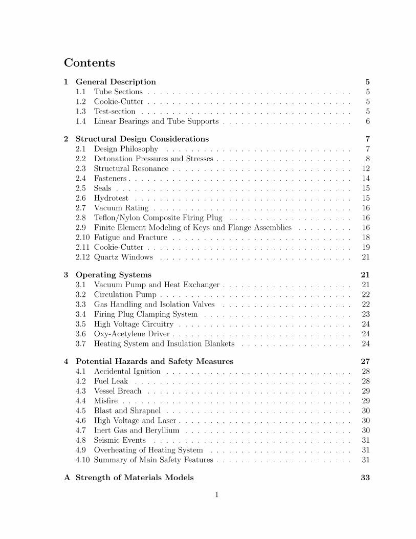
1 General Description 51.1 Tube Sections . . . . . . . . . . . . . . . . . . . . . . . . . . . . . . . . . 51.2 Cookie-Cutter . . . . . . . . . . . . . . . . . . . . . . . . . . . . . . . . . 51.3 Test-section . . . . . . . . . . . . . . . . . . . . . . . . . . . . . . . . . . 51.4 Linear Bearings and Tube Supports . . . . . . . . . . . . . . . . . . . . . 6
2 Structural Design Considerations 72.1 Design Philosophy . . . . . . . . . . . . . . . . . . . . . . . . . . . . . . 72.2 Detonation Pressures and Stresses . . . . . . . . . . . . . . . . . . . . . . 82.3 Structural Resonance . . . . . . . . . . . . . . . . . . . . . . . . . . . . . 122.4 Fasteners . . . . . . . . . . . . . . . . . . . . . . . . . . . . . . . . . . . . 142.5 Seals . . . . . . . . . . . . . . . . . . . . . . . . . . . . . . . . . . . . . . 152.6 Hydrotest . . . . . . . . . . . . . . . . . . . . . . . . . . . . . . . . . . . 152.7 Vacuum Rating . . . . . . . . . . . . . . . . . . . . . . . . . . . . . . . . 162.8 Teflon/Nylon Composite Firing Plug . . . . . . . . . . . . . . . . . . . . 162.9 Finite Element Modeling of Keys and Flange Assemblies . . . . . . . . . 162.10 Fatigue and Fracture . . . . . . . . . . . . . . . . . . . . . . . . . . . . . 182.11 Cookie-Cutter . . . . . . . . . . . . . . . . . . . . . . . . . . . . . . . . . 192.12 Quartz Windows . . . . . . . . . . . . . . . . . . . . . . . . . . . . . . . 21
3 Operating Systems 213.1 Vacuum Pump and Heat Exchanger . . . . . . . . . . . . . . . . . . . . . 213.2 Circulation Pump . . . . . . . . . . . . . . . . . . . . . . . . . . . . . . . 223.3 Gas Handling and Isolation Valves . . . . . . . . . . . . . . . . . . . . . 223.4 Firing Plug Clamping System . . . . . . . . . . . . . . . . . . . . . . . . 233.5 High Voltage Circuitry . . . . . . . . . . . . . . . . . . . . . . . . . . . . 243.6 Oxy-Acetylene Driver . . . . . . . . . . . . . . . . . . . . . . . . . . . . . 243.7 Heating System and Insulation Blankets . . . . . . . . . . . . . . . . . . 24
4 Potential Hazards and Safety Measures 274.1 Accidental Ignition . . . . . . . . . . . . . . . . . . . . . . . . . . . . . . 284.2 Fuel Leak . . . . . . . . . . . . . . . . . . . . . . . . . . . . . . . . . . . 284.3 Vessel Breach . . . . . . . . . . . . . . . . . . . . . . . . . . . . . . . . . 294.4 Misfire . . . . . . . . . . . . . . . . . . . . . . . . . . . . . . . . . . . . . 294.5 Blast and Shrapnel . . . . . . . . . . . . . . . . . . . . . . . . . . . . . . 304.6 High Voltage and Laser . . . . . . . . . . . . . . . . . . . . . . . . . . . . 304.7 Inert Gas and Beryllium . . . . . . . . . . . . . . . . . . . . . . . . . . . 304.8 Seismic Events . . . . . . . . . . . . . . . . . . . . . . . . . . . . . . . . 314.9 Overheating of Heating System . . . . . . . . . . . . . . . . . . . . . . . 314.10 Summary of Main Safety Features . . . . . . . . . . . . . . . . . . . . . . 31
A Strength of Materials Models 33
1

B Analytical Estimation of the Flexural Wave Speed in a Tube underDetonation Loading 34B.1 Steady-State (infinite length) Thin-Walled Formulation including Shear
and Rotary Inertia . . . . . . . . . . . . . . . . . . . . . . . . . . . . . . 34B.2 Simplified Steady-State (infinite length) Thin-Walled Formulation not in-
cluding Shear and Rotary Inertia . . . . . . . . . . . . . . . . . . . . . . 35
2
List of Figures
1 A perspective view of the GALCIT Detonation Tube with the soot foilinserted for cell size measurements. The flexible silicone rubber heatersand the steel braces that clamp down the tube are not shown here. . . . 6
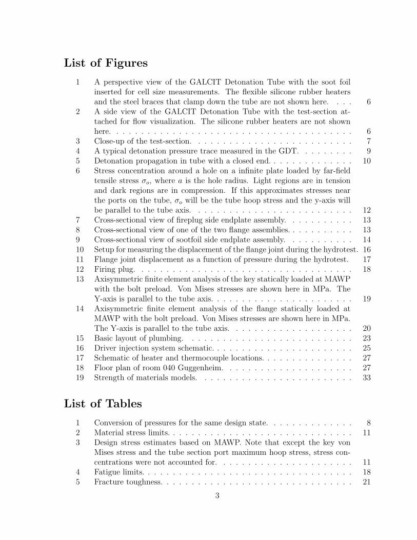
2 A side view of the GALCIT Detonation Tube with the test-section at-tached for flow visualization. The silicone rubber heaters are not shownhere. . . . . . . . . . . . . . . . . . . . . . . . . . . . . . . . . . . . . . . 6
3 Close-up of the test-section. . . . . . . . . . . . . . . . . . . . . . . . . . 74 A typical detonation pressure trace measured in the GDT. . . . . . . . . 95 Detonation propagation in tube with a closed end. . . . . . . . . . . . . . 106 Stress concentration around a hole on a infinite plate loaded by far-field
tensile stress σo, where a is the hole radius. Light regions are in tensionand dark regions are in compression. If this approximates stresses nearthe ports on the tube, σo will be the tube hoop stress and the y-axis willbe parallel to the tube axis. . . . . . . . . . . . . . . . . . . . . . . . . . 12
7 Cross-sectional view of fireplug side endplate assembly. . . . . . . . . . . 138 Cross-sectional view of one of the two flange assemblies. . . . . . . . . . . 139 Cross-sectional view of sootfoil side endplate assembly. . . . . . . . . . . 1410 Setup for measuring the displacement of the flange joint during the hydrotest. 1611 Flange joint displacement as a function of pressure during the hydrotest. 1712 Firing plug. . . . . . . . . . . . . . . . . . . . . . . . . . . . . . . . . . . 1813 Axisymmetric finite element analysis of the key statically loaded at MAWP
with the bolt preload. Von Mises stresses are shown here in MPa. TheY-axis is parallel to the tube axis. . . . . . . . . . . . . . . . . . . . . . . 19
14 Axisymmetric finite element analysis of the flange statically loaded atMAWP with the bolt preload. Von Mises stresses are shown here in MPa.The Y-axis is parallel to the tube axis. . . . . . . . . . . . . . . . . . . . 20
15 Basic layout of plumbing. . . . . . . . . . . . . . . . . . . . . . . . . . . 2316 Driver injection system schematic. . . . . . . . . . . . . . . . . . . . . . . 2517 Schematic of heater and thermocouple locations. . . . . . . . . . . . . . . 2718 Floor plan of room 040 Guggenheim. . . . . . . . . . . . . . . . . . . . . 2719 Strength of materials models. . . . . . . . . . . . . . . . . . . . . . . . . 33
List of Tables
1 Conversion of pressures for the same design state. . . . . . . . . . . . . . 82 Material stress limits. . . . . . . . . . . . . . . . . . . . . . . . . . . . . . 113 Design stress estimates based on MAWP. Note that except the key von
Mises stress and the tube section port maximum hoop stress, stress con-centrations were not accounted for. . . . . . . . . . . . . . . . . . . . . . 11
4 Fatigue limits. . . . . . . . . . . . . . . . . . . . . . . . . . . . . . . . . . 185 Fracture toughness. . . . . . . . . . . . . . . . . . . . . . . . . . . . . . . 21
3

6 Valve ratings. . . . . . . . . . . . . . . . . . . . . . . . . . . . . . . . . . 227 Heating system control zones. Heater output is listed as number of heaters
× wattage per heater. . . . . . . . . . . . . . . . . . . . . . . . . . . . . 26
4
1 General Description
The GALCIT detonation tube (GDT) is designed for use in fundamental studies ofgaseous detonations. The facility consists of three cylindrical tube sections, a ‘cookie-cutter,’ and an optically accessible test-section. The vessel was designed to contain dy-namic reflected shock pressure loadings of up to 1450 psi (100 bar). The tube sections areconnected by highly customized flanged joints that do not conform to ASME standards.A 10 kW electrical heating system and fiberglass insulation blankets were installed tostudy detonations of vapor-phase fuel-air mixtures with initial temperatures above roomtemperature. The tube can be evenly heated up to 100◦C from room temperature in 4hours.
1.1 Tube Sections
The tube sections are made of spin-cast 304L stainless steel honed on the inside to a63 micro-in finish. Each tube section is 8 ft long, and has an internal diameter of 11in and an outer diameter of 13 in. Each section also has 12 ports for instrumentationand plumbing mounts. Grooves have been cut near the ends of each tube section inorder to hold retaining rings that transfer longitudinal forces between the flange and thetube. The flanges and endplates are made of 4340 high strength carbon steel, 20 inchesin diameter, and 3.7 inches thick. Each flange assembly or endplate assembly is boltedtogether by sixteen 1” diameter grade 8 bolts (figure 1).
1.2 Cookie-Cutter
For flow visualization, a square tube cross-section is required. A ‘cookie-cutter’ is usedto effectively ‘cut out’ a wave of square cross-section from the incident detonation wave.The cookie-cutter consists of four 1/2” thick aluminum plates welded together to forma 6 inch square cross-section, and is mounted inside the end of the last cylindrical tubesection. The edges of these plates are relatively sharp to ‘cut’ the oncoming wave withminimal disturbance. The cutter is fitted into a 3 inch thick holding flange that couplesdirectly with the test-section.
1.3 Test-section
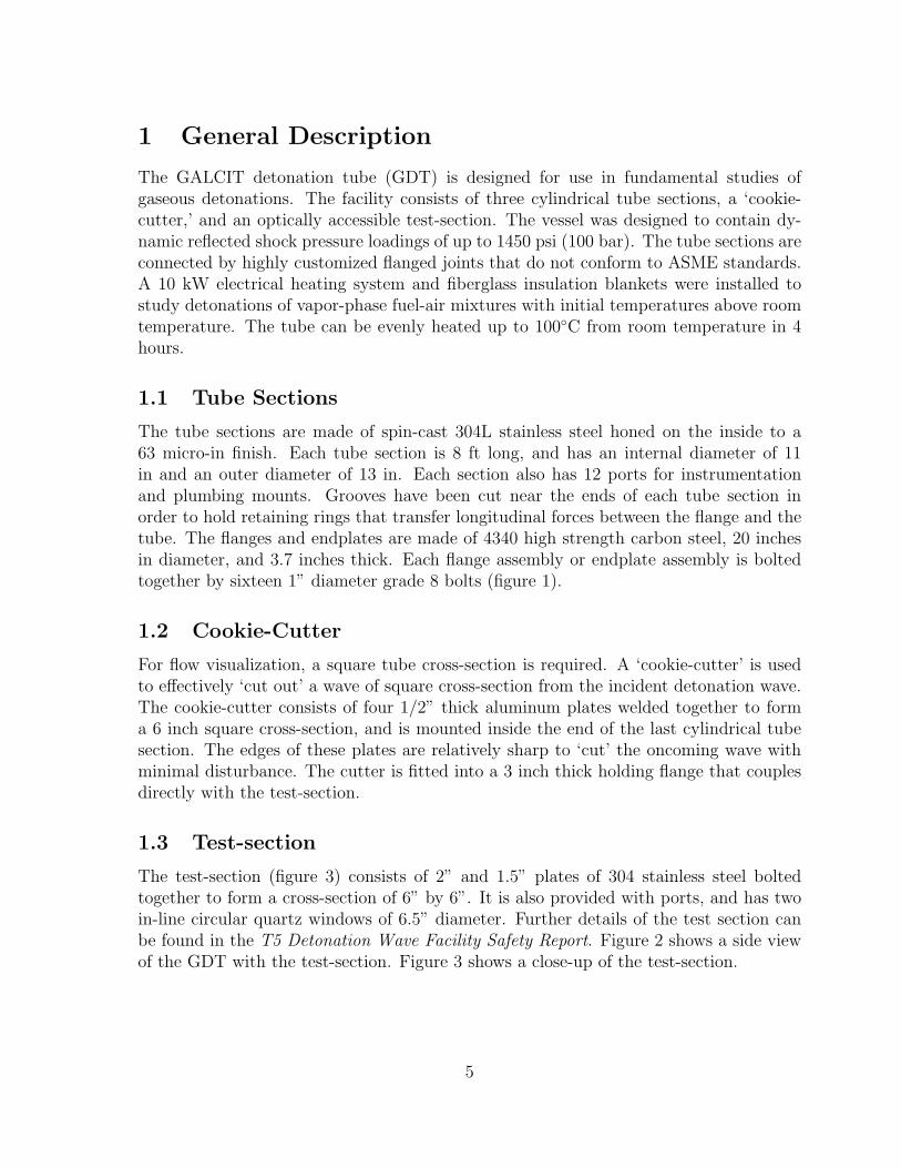
The test-section (figure 3) consists of 2” and 1.5” plates of 304 stainless steel boltedtogether to form a cross-section of 6” by 6”. It is also provided with ports, and has twoin-line circular quartz windows of 6.5” diameter. Further details of the test section canbe found in the T5 Detonation Wave Facility Safety Report. Figure 2 shows a side viewof the GDT with the test-section. Figure 3 shows a close-up of the test-section.
5

Figure 1: A perspective view of the GALCIT Detonation Tube with the soot foil insertedfor cell size measurements. The flexible silicone rubber heaters and the steel braces thatclamp down the tube are not shown here.
Figure 2: A side view of the GALCIT Detonation Tube with the test-section attachedfor flow visualization. The silicone rubber heaters are not shown here.
1.4 Linear Bearings and Tube Supports
Each section of the vessel is mounted on two structural steel square tubes with cut-outsthat are shaped to fit the tube surface. The tubes are held down by 0.063 inch straps
6

Figure 3: Close-up of the test-section.
bolted to the structural steel tubes. The structural steel is bolted to THK HSR-35 linearbearing blocks that travel on rail sections. This enables the vessel to move freely, as asingle unit, a maximum of 12” in each direction. The linear bearings are rated for muchhigher weights than that of the sections, and are also designed to sustain some momentloading. The travel of the bearings is limited by aluminum blocks mounted the ends ofthe rails. 0.25 inch thick phenolic blocks are installed between the linear bearing blocksand the structural streel tubes to minimize the heat loss to the rails.
2 Structural Design Considerations
2.1 Design Philosophy
A fully dynamic, transient, and non-linear contact model of the GDT’s response todetonations would be realistic but computationally expensive. For design of the GDT, themore pragmatic strength of materials approach was used with a static equivalent pressure
7
Design Pressure psi barDynamic CJ pressure magnitude 580 40
Static equivalent CJ pressure 1160 80Dynamic reflected shock pressure magnitude 1450 100
Static equivalent reflected shock pressure, or MAWP 2900 200Hydrostatic proof pressure 2900 200
Table 1: Conversion of pressures for the same design state.
concept. At places with stress concentrations where complicated geometry causes thestrength of material approach to fail, static finite element analysis was used. The designprinciple was to keep stresses at a safety factor of two with respect to the material staticyield stress in places sufficiently far away from stress concentrations such as grooves andholes. A small amount of localized yielding is accepted at these stress concentrationzones, but the stresses are never permitted to venture near the ultimate stress.
2.2 Detonation Pressures and Stresses
There are three types of phenomenon that are experienced by a detonation vessel andare of interest to its structural designer: 1) direct or ‘prompt’ initiation of detonation,2) deflagration to detonation transition (DDT), 3) resonance due to flexural waves. TheGDT is designed for the first case. It is not designed for DDT or flexural wave speedexperiments, but can be used for such experiments at low pressures.
The static equivalent pressure is defined as twice the amplitude of the correspondingdynamic pressure. This definition is based on that when the detonation wave velocity issufficiently far away from the flexural wave speed of the structure, the stresses inducedby the dynamic pressure is at most twice that of the stress induced by a static pressureof the same amplitude. According to Shepherd (1992), when the detonation wave reflectsoff as a shock wave from the closed end of a detonation tube, the pressure is about 2.5times the Chapman-Jouguet pressure, PCJ . Hence, static design formulas were used toapproximate maximum dynamic stresses with 2 × 2.5 × PCJ as the ‘static equivalentreflected shock pressure.’ As long as there is no structural resonance, this approximationis a conservative upper bound. For example, the maximum dynamic hoop stress in theGDT induced by the reflected shock wave is approximated by
σH,max =2 × 2.5 × PCJ
Rt(1)
where R and t are the tube radius and wall-thickness, respectively. The design pressuresare shown in table 1 for the same design state.
Such calculations depend on the value chosen for the dynamically applied pressure.A typical detonation trace picked up by a pressure transducer located at the tube wallis shown in figure 4. The one-dimensional pressure profile of a detonation can be labeledas shown in figure 5.
8
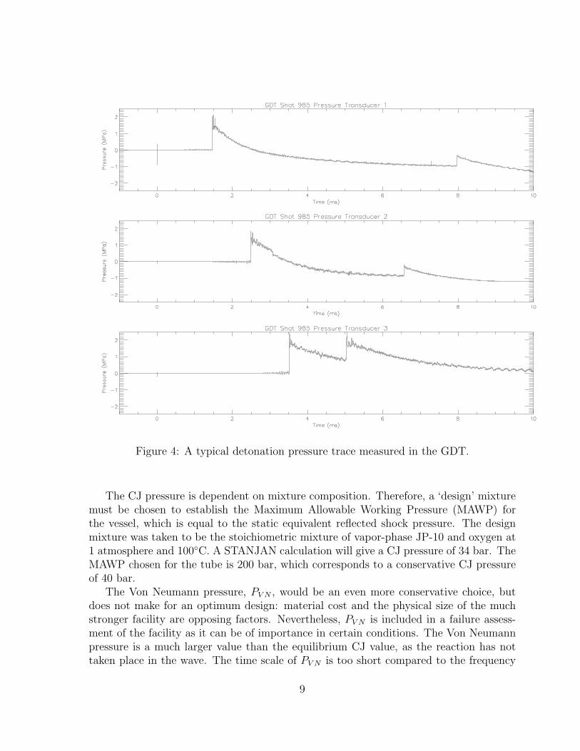
Figure 4: A typical detonation pressure trace measured in the GDT.
The CJ pressure is dependent on mixture composition. Therefore, a ‘design’ mixturemust be chosen to establish the Maximum Allowable Working Pressure (MAWP) forthe vessel, which is equal to the static equivalent reflected shock pressure. The designmixture was taken to be the stoichiometric mixture of vapor-phase JP-10 and oxygen at1 atmosphere and 100◦C. A STANJAN calculation will give a CJ pressure of 34 bar. TheMAWP chosen for the tube is 200 bar, which corresponds to a conservative CJ pressureof 40 bar.
The Von Neumann pressure, PV N , would be an even more conservative choice, butdoes not make for an optimum design: material cost and the physical size of the muchstronger facility are opposing factors. Nevertheless, PV N is included in a failure assess-ment of the facility as it can be of importance in certain conditions. The Von Neumannpressure is a much larger value than the equilibrium CJ value, as the reaction has nottaken place in the wave. The time scale of PV N is too short compared to the frequency
9

0
0��
0��
0��
0��
�
���
0 0�� 0�� 0�� 0�� � ��� ��� ��� ���
distance
pressure
p2 ��p ��
p�
p �
stationary reactantse� ansion �a�estationary ro��cts
�etonation
v cj
Figure 5: Detonation propagation in tube with a closed end.
response of the structure. Experiments done by Beltman and Shepherd (1998) on theGDT proved that the amplitudes of dynamic strains induced by detonations correspondto PCJ rather than PV N . However, PV N can be important in the loading of the facility ifthe pressure is not relieved quickly enough by the reaction. This can arise, for example,in the case of a mixture that has a very large cell size, and thus a large induction zonelength. It is neccessary for the operator of the facility to avoid these regimes, especiallyat high initial pressures. Cell size estimates using ZND calculations, a low pressure ex-perimental study and known data are neccessary along with the estimates for PV N andPCJ to assess the suitablility of a particular mixture.
It was assumed that the dynamic loading factor is at most two when there is nostructural resonance, and the peak loading behind the normally reflected CJ wave isabout 10 MPa (or about 100 bar or 1450 psi). The facility was designed with this valuein mind, with the requirement that any given part (except small stress concentratedregions) under this loading may statically yield at no less than twice this pressure (factorof safety of 2).
The tube section’s port edge maximum stress in table 3 requires some explanation.The regions being described are those near the ports and they are stress concentrations.The stress is calculated by multiplying the tube section hoop stress by a factor of 3. Thisis justified by the linear elastic theory, which predicts that the maximum stress arounda circular hole in an infinite flat plate is 3 times the far-field tensile stress (see figure 6).Two very localized yield regions are indicated by the two light regions around the holeedge. However, in reality the factor never reaches 3 because of the stress relief due tolocal plastic deformation. Nevertheless, the port edges should be one of the first places
10

Material GDT Component Yield Stress (ksi) Ultimate TensileStress (ksi)
SS304L Tube sections 39 704340 Flanges, keys, and endplates 66 95
Alloy steel Bolts 130 170Al6061-T6 Port Plugs 40 45
Teflon at 23◦C Fireplug 1.3 3Teflon at 121◦C Fireplug 0.5 -
Nylon (Zytel 101) at 23◦C Fireplug 8.5 -Nylon (Zytel 101) at 121◦C Fireplug 4.0 -
Table 2: Material stress limits.
Safety Factors w. r. t. :Part and Loading Type Load at MAWP (ksi) Yield Stress UTS
Tube section, hoop stress 17.4 2.2 4.0Tube section, groove hoop stress 23.6 1.7 3.0
Tube section, port edge maximum stress 52.2 0.7 1.3Flange, bending stress 21.3 3.1 4.5
Key, ‘average’ von Mises stress (from FEM) 23.0 2.9 4.2Endplate bending stress 15.2 4.3 6.3Flange bolts axial stress 37.5 3.5 4.5Port plug shear stress 1.5 27.6 31.0
Port plug bending stress 7.9 5.1 5.7Port plug bolts axial stress 12.9 10.1 13.2
Fireplug shear stress at 100◦C (Nylon) 1.5 2.8 –
Table 3: Design stress estimates based on MAWP. Note that except the key von Misesstress and the tube section port maximum hoop stress, stress concentrations were notaccounted for.
11

to check for cracks during maintenance after a high number of shots.
Figure 6: Stress concentration around a hole on a infinite plate loaded by far-field tensilestress σo, where a is the hole radius. Light regions are in tension and dark regions arein compression. If this approximates stresses near the ports on the tube, σo will be thetube hoop stress and the y-axis will be parallel to the tube axis.
2.3 Structural Resonance
Experiments were conducted by Beltman and Shepherd (1998) on the GDT to studythe effects of flexural wave excitation. Measured strains exceeded the static strain by afactor of 3.9 when the detonation wave speed approached the GDT’s flexural wave speedof 1450 m/s (formulas on how to estimate this speed is given in the Appendix). Thestatic strain here was defined as
εstatic =(PCJ − Patm)R
Et(2)
This means that when the detonation wave speed approached the flexural wave speed,static design formulas using the static equivalent reflected shock pressure would stillconservatively overestimate the stresses by a factor of 2×2.5
3.9= 1.3 (of course, this has not
taken into account the stress concentrations at the groove corners and ports).
12

Figure 7: Cross-sectional view of fireplug side endplate assembly.
Figure 8: Cross-sectional view of one of the two flange assemblies.
It should be noted that the resonating strains in these experiments were induced bythe incident detonation waves. The reflected shock waves ran at different speeds than theincident detonation waves. The experiments did not investigate the effects of resonanceof the GDT caused by reflected shock waves running at the flexural wave speed. On theother hand, reflected shock waves decay quickly over distance (see the typical pressure
13
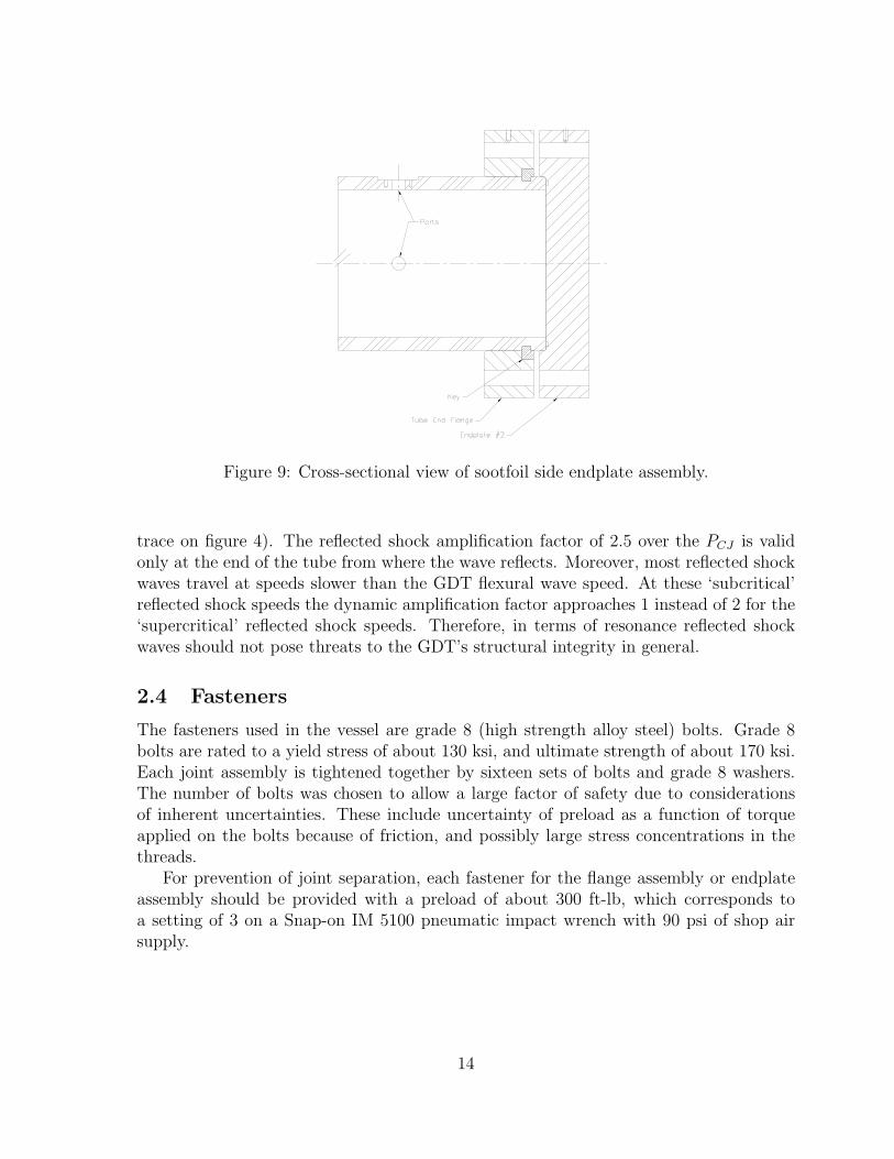
Figure 9: Cross-sectional view of sootfoil side endplate assembly.
trace on figure 4). The reflected shock amplification factor of 2.5 over the PCJ is validonly at the end of the tube from where the wave reflects. Moreover, most reflected shockwaves travel at speeds slower than the GDT flexural wave speed. At these ‘subcritical’reflected shock speeds the dynamic amplification factor approaches 1 instead of 2 for the‘supercritical’ reflected shock speeds. Therefore, in terms of resonance reflected shockwaves should not pose threats to the GDT’s structural integrity in general.
2.4 Fasteners
The fasteners used in the vessel are grade 8 (high strength alloy steel) bolts. Grade 8bolts are rated to a yield stress of about 130 ksi, and ultimate strength of about 170 ksi.Each joint assembly is tightened together by sixteen sets of bolts and grade 8 washers.The number of bolts was chosen to allow a large factor of safety due to considerationsof inherent uncertainties. These include uncertainty of preload as a function of torqueapplied on the bolts because of friction, and possibly large stress concentrations in thethreads.
For prevention of joint separation, each fastener for the flange assembly or endplateassembly should be provided with a preload of about 300 ft-lb, which corresponds toa setting of 3 on a Snap-on IM 5100 pneumatic impact wrench with 90 psi of shop airsupply.
14

2.5 Seals
Tube joints, ports, and fittings mating with the tube are sealed using O-rings. These areface seals, with additional industrial static seals implemented at joints that are expectedto move. O-rings are made of Buna-N which is inert to mixtures of interest. Buna O-rings are rated up to 135◦C. Pressure limit depends on the type of seal (whether it isa face seal or industrial seal), operating temperature, loading rate, and tolerance. Forface seals, Parker (1992) reported static pressure limits up to 200 ksi for good metalto metal contact. Industrial seals are rated to much lower pressures (on the order of1500 psi for static pressures), but the pressure goes up as diametral clearance decreases(note that at zero diametral clearance the industrial seal becomes a face seal). Moreover,under short time scale impulsive loading the viscoelastic O-rings respond elastically. Thisincreases the sealing capability since O-ring damage by creep and extrusion is prevented.The O-rings in the hydraulic clamps are made of Viton to withstand the high hydraulicpressures up to 7500 psi at over 100◦C.
2.6 Hydrotest
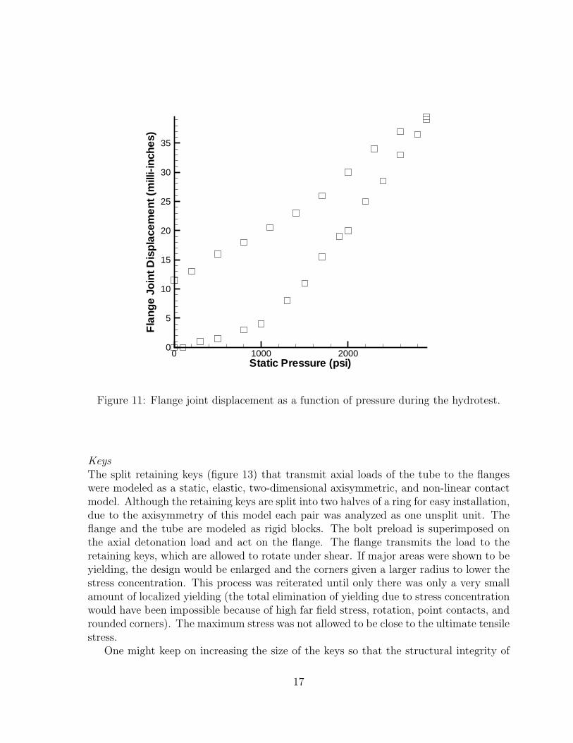
The GALCIT Detonation Tube was statically hydrotested to 2900 psi. The tube’s originaltotal volume is 27560 in3, but 316 in3 was needed during pressurization in addition tothis volume of water to account for water compressibility and tube expansion. Thedisplacement of one of the joints was measured by a dial gage as the GDT was pressurizedand depressurized over time. A hysteresis loop was recorded and shown in figure 11. Thedial gage was positioned as shown schematically in figure 10.
No leakage was observed during the hydrotest. However, slight damage by extrusionwas observed on some of the face seals in the flange assemblies and endplate assembliesafter the hydrotest. The damaged seals were replaced by new ones after the hydrotest.This type of damage, as mentioned above in the Seals section, is caused by creep as aresult of static loading. It is not expected to happen for impulsive detonation loading.Such damage has not been observed for detonation loading during the history of theGDT’s operations.
Lueder’s lines parallel to the tube axis were observed in the groove corners. This con-firmed the predicted mild, localized yielding due to stress concentration, but is acceptablesince SS304L is a ductile material. The yielded regions should now be work-hardened,making them less susceptible to further plastic deformation, but these corners should beinspected at regular intervals to make sure that cracks do not develop. No Lueder’s lineswere observed at the port edges.
The dynamic pressure corresponding to 2900 psi is 1450 psi (100 bar). This meansthat for safe operation of the tube, the dynamic reflected shock pressure amplitude shouldnever exceed 1450 psi.
15

Figure 10: Setup for measuring the displacement of the flange joint during the hydrotest.
2.7 Vacuum Rating
As of 11/13/2000, the tube is capable of reaching 45 millitorr with the existing Kinneypump, a pumping time of about 1/2 hour, and the test section attached. Without thetest section it can reach 40 millitorr in 1/2 hour. The leak rate is about 10 millitorr/minwith the test section attached, and about 7 millitorr/min without the test section.
2.8 Teflon/Nylon Composite Firing Plug
The firing plug is composed of a teflon piece, a nylon piece, and two steel electrodes(figure 12). Teflon was chosen for its being chemically inert to mixtures of interest, andnylon for its strength at elevated temperatures. The plug is configured such that theteflon would only take mild axial loads while the nylon would transmit the shear stressesat the base and withstand the stress concentrations. The corrosive gases are isolatedfrom the nylon piece by an industrial O-ring seal on the teflon.
The firing plug was replaced by a dummy plug made of aluminum during the hy-drotest. The reason is to protect the teflon and nylon, which are both rate-dependentviscoelastic materials and are subjected to creep damage under high static loading.
2.9 Finite Element Modeling of Keys and Flange Assemblies
The finite element analysis of the design of the keys and flange assemblies was carriedout by the commercial software package LS-DYNA to estimate the stress concentrations.
16
Static Pressure (psi)
Fla
nge
Join
tDis
plac
emen
t(m
illi-in
ches
)
0 1000 20000
5
10
15
20
25
30
35
Figure 11: Flange joint displacement as a function of pressure during the hydrotest.
KeysThe split retaining keys (figure 13) that transmit axial loads of the tube to the flangeswere modeled as a static, elastic, two-dimensional axisymmetric, and non-linear contactmodel. Although the retaining keys are split into two halves of a ring for easy installation,due to the axisymmetry of this model each pair was analyzed as one unsplit unit. Theflange and the tube are modeled as rigid blocks. The bolt preload is superimposed onthe axial detonation load and act on the flange. The flange transmits the load to theretaining keys, which are allowed to rotate under shear. If major areas were shown to beyielding, the design would be enlarged and the corners given a larger radius to lower thestress concentration. This process was reiterated until only there was only a very smallamount of localized yielding (the total elimination of yielding due to stress concentrationwould have been impossible because of high far field stress, rotation, point contacts, androunded corners). The maximum stress was not allowed to be close to the ultimate tensilestress.
One might keep on increasing the size of the keys so that the structural integrity of
17
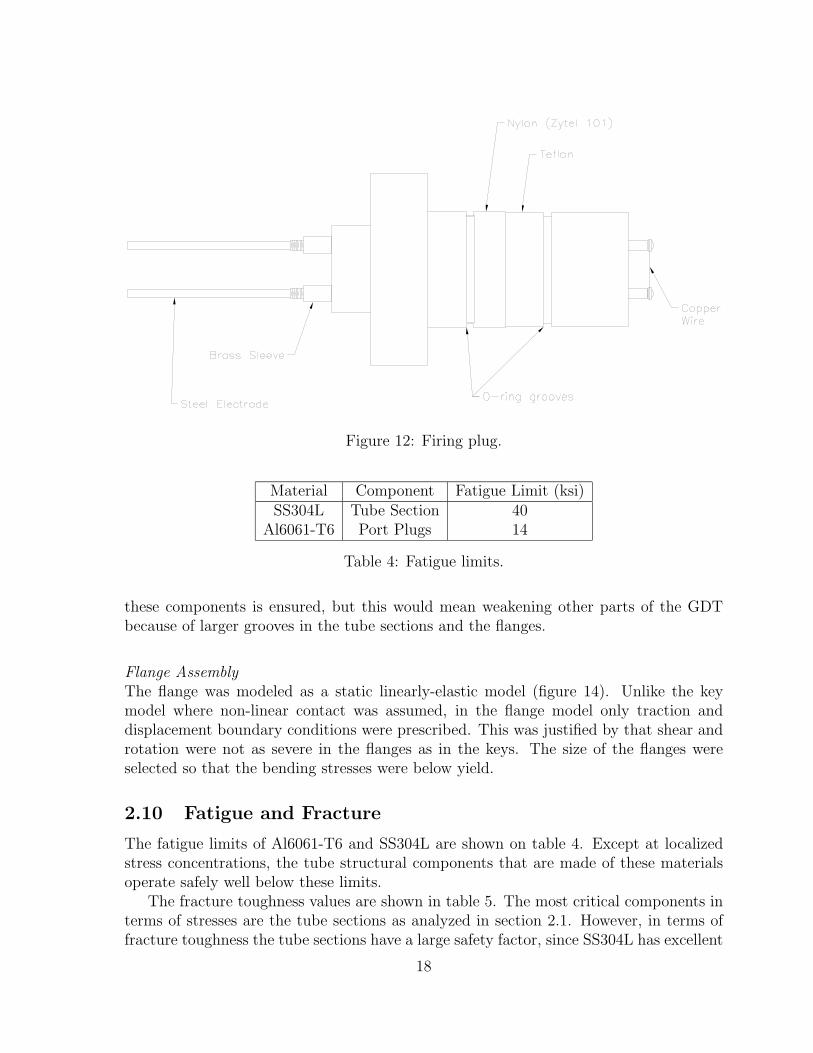
Figure 12: Firing plug.
Material Component Fatigue Limit (ksi)SS304L Tube Section 40
Al6061-T6 Port Plugs 14
Table 4: Fatigue limits.
these components is ensured, but this would mean weakening other parts of the GDTbecause of larger grooves in the tube sections and the flanges.
Flange AssemblyThe flange was modeled as a static linearly-elastic model (figure 14). Unlike the keymodel where non-linear contact was assumed, in the flange model only traction anddisplacement boundary conditions were prescribed. This was justified by that shear androtation were not as severe in the flanges as in the keys. The size of the flanges wereselected so that the bending stresses were below yield.
2.10 Fatigue and Fracture
The fatigue limits of Al6061-T6 and SS304L are shown on table 4. Except at localizedstress concentrations, the tube structural components that are made of these materialsoperate safely well below these limits.
The fracture toughness values are shown in table 5. The most critical components interms of stresses are the tube sections as analyzed in section 2.1. However, in terms offracture toughness the tube sections have a large safety factor, since SS304L has excellent
18
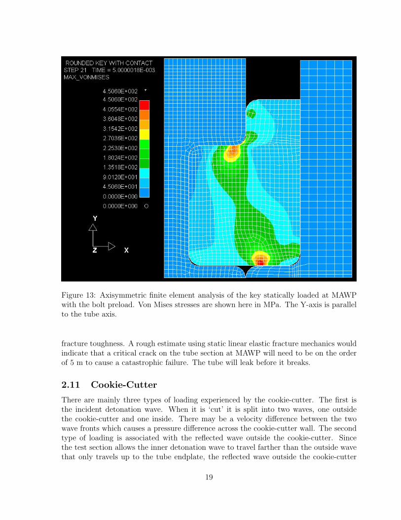
Figure 13: Axisymmetric finite element analysis of the key statically loaded at MAWPwith the bolt preload. Von Mises stresses are shown here in MPa. The Y-axis is parallelto the tube axis.
fracture toughness. A rough estimate using static linear elastic fracture mechanics wouldindicate that a critical crack on the tube section at MAWP will need to be on the orderof 5 m to cause a catastrophic failure. The tube will leak before it breaks.
2.11 Cookie-Cutter
There are mainly three types of loading experienced by the cookie-cutter. The first isthe incident detonation wave. When it is ‘cut’ it is split into two waves, one outsidethe cookie-cutter and one inside. There may be a velocity difference between the twowave fronts which causes a pressure difference across the cookie-cutter wall. The secondtype of loading is associated with the reflected wave outside the cookie-cutter. Sincethe test section allows the inner detonation wave to travel farther than the outside wavethat only travels up to the tube endplate, the reflected wave outside the cookie-cutter
19
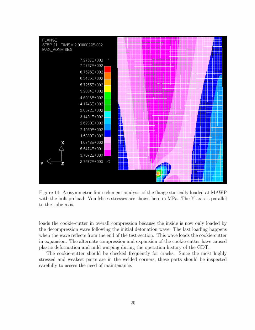
Figure 14: Axisymmetric finite element analysis of the flange statically loaded at MAWPwith the bolt preload. Von Mises stresses are shown here in MPa. The Y-axis is parallelto the tube axis.
loads the cookie-cutter in overall compression because the inside is now only loaded bythe decompression wave following the initial detonation wave. The last loading happenswhen the wave reflects from the end of the test-section. This wave loads the cookie-cutterin expansion. The alternate compression and expansion of the cookie-cutter have causedplastic deformation and mild warping during the operation history of the GDT.
The cookie-cutter should be checked frequently for cracks. Since the most highlystressed and weakest parts are in the welded corners, these parts should be inspectedcarefully to assess the need of maintenance.
20
Material Component Fracture Toughness, Jc (kJ/m2)SS304L Tube Section 672
Al6061-T6 Port Plugs 124340 Keys, Flanges, and Endplates 13
Table 5: Fracture toughness.
2.12 Quartz Windows
Quartz was chosen for its excellent optical properties. However, the brittle nature ofquartz makes it a poor structural material for withstanding the detonation’s impulsiveloading. Small cracks often develop near or at the surface of these windows. They arereplaced often.
3 Operating Systems
A number of different sub-systems are operated. These are:
1. Vacuum pump and heat exchanger
2. Circulation pump
3. Gas handling and isolation valves
4. Firing plug clamping system
5. High Voltage circuitry
6. Oxy-Acetylene driver
7. Heating system
With the exception of the vacuum pump, its heat exchanger, and the heating system,all the equipment of the facility can be operated from the firing end of the detonationtube (figure 18).
3.1 Vacuum Pump and Heat Exchanger
An overhead vacuum line is connected to the detonation tube through flexible hose andby way of electro-pneumatic valves V1 and V2 (figure 15). This vacuum line is connectedto a Kinney KTC-112 vacuum pump (not shown in the figures) which can evacuate thefacility to pressures as low as 14 millitorr. A heat exchanger is used to provide coolingwater to the pump.
21

Valves Swagelok Model Maximum Static Pressure at TemperatureV1, V2, T1, T2 SS-65-TF16-33DCB 2.2 ksig @ 25◦C, 1.5 ksig @ 100◦C
E1, G1, D SS-83KS8 6.0 ksig @ 25◦C, 2.0 ksig @ 100◦CA, O SS-62TS4-31DCB 2.2 ksig @ 25◦C
Table 6: Valve ratings.
3.2 Circulation Pump
A Senior Flexonics MB-302 pump was used to circulate fuel and oxidizer. The pumpwas subsequently modified to satisfy the elevated temperature requirement. Since themotor was rated up to only about 40◦C, the bellows was separated from the motor sothat only the bellows was heated. They were connected by a one foot long shaft anda flexible polyurethane coupling. The shaft was supported by two bearing supports.The bellows housing was lined by a rope heater, and a propeller was mounted on to theend of the motor shaft to induce convection so that the equilibrium temperature in thebellows housing can be attained quickly. The bellows housing was covered by a fiberglassinsulation blanket. The whole assembly sits on a vibrating damping pad, and is coveredby an explosion-proof steel box.
3.3 Gas Handling and Isolation Valves
The gas lines come into the room from a bottle farm located outside the building. Pro-vision has been made in the plumbing for a total of seven gases. These are Hydrogen,Methane, Ammonia, Nitrous Oxide, Oxygen, Nitrogen and Argon. Detailed descriptionof the gas supply at the bottle form is given in the the Hydrogen Jet Facility SafetyReport.
A control panel is mounted on the gas handling rack. This panel contains the switchesfor the various valves shown in figure 15, and also has the firing switch for the explodingwire circuitry. Valves V1, V2, T1, T2, E1, G1, A, O, and D have opto-interruptersmounted on them to sense their open and closed positions. These are linked to indicatorson the control panel. The signal lines from the closed position interrupters are fed intoa logic circuit that prevents the operation of valve D when the vacuum system is beingused.
Gases are introduced into the tube by way of a ball valve and a main needle valve(N1) and the desired mixture composition is produced by monitoring the MKS gauge andusing the method of partial pressures. The statically rated pressures and temperaturesof the valves are listed in table 6. Gas lines are made of stainless steel tubing withcompatible Swagelok fittings and are rated to at least 200 bars (static).
Although the electro-pneumatic valves are not rated to take high temperatures, thedetonation wave gives off only a flash heat which is quickly absorbed by the structureand the steady state temperature is much lower than the CJ temperature due to thestructure’s high heat capacity. However, occasionally some teflon seats inside these valves
22

Figure 15: Basic layout of plumbing.
did burn through and became a leak-through which cannot be detected outside theplumbing system.
3.4 Firing Plug Clamping System
For operational ease the firing plug can be removed to replace the copper wire. In orderto hold this plug in place and be able to sustain pressures experienced during a test, fourwork-holding clamps (Carr-Lane Roemheld 920-EX) are used. These are operated by amanual pump that raises the pressure in the hydraulic system. The clamping units havearms that first move forward and then vertically down. They clamp on top of a stainlesssteel backing plate that covers the firing plug. This is needed in order to transmit thepressure uniformly to the teflon/nylon plug.
A static equivalent force of 8,200 lbs will be experienced by the plug at the maximumallowable Chapman-Jouguet static equivalent pressure of 1160 psi (80 bar). The fourclamps can provide a total static preload of up to 26 klbs at 7500 psi hydraulic manifold
23

pressure. Historical detonation pressure traces in the GDT (for example, figure 4) haveshown that the maximum pressure experienced by the firing plug end is no higher than theCJ pressure. The reflected shock pressure has already decayed to below the CJ pressureat this point. Viton seals, which are rated to 150oC at the use hydraulic pressures, areused in the hydraulic clamps. The factor of safety with respect to the static preload is3.2.
3.5 High Voltage Circuitry
For direct initiation of detonations, a blast wave is generated inside the tube by explod-ing a copper wire and producing a rapid electrical discharge. High voltage capacitors(Maxwell) are charged typically to 12 kV using a power supply (Hipotronics) with thedischarge across the copper wire held off by a spark gap (EG&G GP-20B). The sparkgap is triggered by a high voltage pulse from a trigger module (EG&G TM-11). Thecopper wire is mounted across two copper electrodes fitted on a teflon/nylon plug. Thewire is replaced before each shot. The firing circuit is locked out by the logic circuit onthe operating panel if any gas handling or isolation valve is not fully closed.
3.6 Oxy-Acetylene Driver
To promote the initiation of detonation a mixture of oxygen and acetylene is injectedin the vicinity of the exploding wire just before discharging the capacitors across thewire. Figure 16 is a schematic of the set-up. Valves A and O are 1/4” electro-pneumaticball valves and valve D is a 1/2”electro-pneumatic ball valve. A and O control the gasflow from the acetylene and oxygen regulators respectively, while valve D controls theoverall flow into the detonation tube. The controlling circuit opens the valves for a presettime period, and arms and fires the TM-11 a second preset time period after valve Dhas closed. The time for which the valves are open determines the total amount of oxy-acetylene delivered, for a given regulator setting at the bottles. This is determined beforethe run and subtracted from the final desired test pressure before determining the partialpressures needed to prepare the test mixture. The amount of gas as well as the amountof time before ignition, both determine the effectiveness of injected mixture in promotingdetonation initiation.
3.7 Heating System and Insulation Blankets
The heating system can heat up the tube and its plumbing system from room temperatureto 100◦C in 4 hours, and is divided into nineteen heating zones (figure 17), with onethermocouple and one controller for each zone. The heaters were sized and chosen afterthe heat capacity of the GDT and its plumbing system was considered. While controlcomponents were made by Watlow, the flexible silicone rubber tape heaters for the tubewere made by Watlow and the flexible rope heaters for the plumbing were made byOmega. Twelve zones control the heating of the tube, one zone control the heating of
24
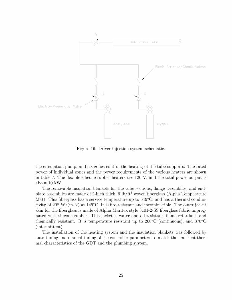
Figure 16: Driver injection system schematic.
the circulation pump, and six zones control the heating of the tube supports. The ratedpower of individual zones and the power requirements of the various heaters are shownin table 7. The flexible silicone rubber heaters use 120 V, and the total power output isabout 10 kW.
The removable insulation blankets for the tube sections, flange assemblies, and end-plate assemblies are made of 2-inch thick, 6 lb/ft3 woven fiberglass (Alpha TemperatureMat). This fiberglass has a service temperature up to 649◦C, and has a thermal conduc-tivity of 208 W/(m-K) at 149◦C. It is fire-resistant and incombustible. The outer jacketskin for the fiberglass is made of Alpha Maritex style 3101-2-SS fiberglass fabric impreg-nated with silicone rubber. This jacket is water and oil resistant, flame retardant, andchemically resistant. It is temperature resistant up to 260◦C (continuous), and 370◦C(intermittent).
The installation of the heating system and the insulation blankets was followed byauto-tuning and manual-tuning of the controller parameters to match the transient ther-mal characteristics of the GDT and the plumbing system.
25

Power CurrentZone Limit (kW) Limit (Amps) Location Heater Output (W)
1 1.6 13.3 Tube Section 4 × 4002 1.6 13.3 Tube Section 4 × 4003 1.6 13.3 Tube Section 4 × 4004 1.2 10 Flange Assembly 4 × 3005 1.2 10 Flange Assembly 4 × 3006 1.2 10 Tree (Fireplug Side) 2 × 2507 0.6 5 Endflange (Fireplug Side) 2 × 3008 0.6 5 Endflange (Soot Foil Side) 2 × 3009 0.6 5 Endplate (Soot Foil Side) 2 × 30010 1.6 13.3 Endplate & Clamps (Fireplug Side) 2 × 300 + 5 × 12511 1.6 13.3 Circulation Lines 3 × 40012 1.6 13.3 Circulation Lines and Tree (Soot Foil Side) 3 × 400 + 25013 0.6 5 Circulation Pump 40014 0.6 5 Tube Support 2 × 7515 0.6 5 Tube Support 2 × 7516 0.6 5 Tube Support 2 × 7517 0.6 5 Tube Support 2 × 7518 0.6 5 Tube Support 2 × 7519 0.6 5 Tube Support 2 × 75
Table 7: Heating system control zones. Heater output is listed as number of heaters ×wattage per heater.
26

Figure 17: Schematic of heater and thermocouple locations.
Figure 18: Floor plan of room 040 Guggenheim.
4 Potential Hazards and Safety Measures
The three tube sections have a volume of 16 cubic ft and the test section has a volumeof 0.6 cubic ft. Based on a simple heat of formation calculation, 17 cubic ft of a stoi-
27

chiometric hydrogen-oxygen mixture at 300K and 1 atm yields about 3.5 MJ of energy.This is delivered in approximately 3 milliseconds, based on a detonation speed of 2800m/s and 27 ft of travel. The following is a list of possible hazards in the operation of thefacility:
1. Accidental ignition during fill-up of vessel.
2. Fuel leak-explosion hazard external to vessel.
3. Vessel breach due to unplanned explosion, resonance, or vessel fatigue and associ-ated blast, missile and fragmentation hazard.
4. High voltage use in ignition system and high power laser use within laboratorypremises.
5. Inert gas hazard in the operation of the rotating mirror cameras.
6. Vessel breach, gas release and gas ignition due to seismic events.
7. Overheating of the heating system.
For the safe operation of the facility, specific precautions are being taken towards thehazards identified.
4.1 Accidental Ignition
As the trigger circuit is interlocked with the valves of the facility, ignition cannot takeplace during gas filling. Also, the TM-11 trigger module must be switched on and armedbefore firing, reducing further the chances of accidental triggering. Furthermore, the ca-pacitors are not charged up until the gas introduction and mixing processes are complete(see checklist). The only type of ignition that can is possible during fill-up is throughan accidental operation of the glow-plug. However, this cannot take place except inten-tionally, as the glow plug power supply is only connected in the event of a misfire of theexploding wire.
4.2 Fuel Leak
Hydrogen detectors are mounted at points in the ceiling of the room (Fig. 4), with onelocated near the operating rack. The detectors are connected to valves in the main fuellines from the bottle farm located outside the building. These valves will close shut whenthe detectors pick up a concentration of hydrogen of more than 400 ppm, which is lessthan the lower flammability limit of hydrogen in air at 1 atm. The detectors are alsoconnected to the manually armed purge system which is capable of turning over the air inthe room in a few minutes. This purge system can be operated manually or disconnected,but the automatic closing of the fuel valve upon triggering of the hydrogen leak detectorsnever be disarmed. Details of the purge system can be found in the Hydrogen Jet FacilitySafety Report.
28

4.3 Vessel Breach
It is always possible to cause a catastrophic failure of the detonation tube using a testmixture that is energetic enough. Clearly such a vessel failure can be prevented by care-fully avoiding test mixtures that will produce pressures higher than the design MAWPand avoiding structural resonance at high pressures. However, the significant and rela-tively less predictable hazard of deflagration to detonation transition (DDT) is also atissue. Pressures produced in such an event are much higher than the CJ pressure behinda detonation. This means that while a mixture is in principle ‘safe’ if the CJ loadingproduces a reflected pressure that is lower than the MAWP of the vessel, it is possible toexceed the MAWP should a DDT occur in the same mixture. It is virtually impossibleto produce a numerical probability analysis of the DDT hazard, so the risk can only beminimized by ensuring that the detonations are directly initiated, and through significantover-design of the vessel. Specifically, this vessel is designed so that the maximum stressdoes not exceed the yield stress of the material for dynamic reflected shock pressures upto 100 bars. If pressures exceed this by small amounts, the tube will be able to sustainthem with minimal permanent deformation.
The tube grooves are the weakest parts in the tube sections because 1) they havethinner wall thickness and 2) the corners introduce stress concentrations. After a largenumber of high pressure shots, the grooves should be inspected with magnifying glassesfor Lueder’s lines and cracks. The second place to check will be the port edges. Boltpreload on the flange and endplate assemblies should be set to about 300 lb-ft for eachbolt (this can be provided by a Snap-on IM 5100 pneumatic impact wrench with 90 psiof shop air and a setting of 3).
The laboratory is partitioned into two sections (figure 18) to enable safe operationaway from the test-section which is the weakest part in the facility when the quartzwindows are being used. The partitioning wall has 1/4” steel plating in it to reduce thehazard from any flying debris in case of a vessel breach at the test end.
4.4 Misfire
If no burning occurs due to the copper wire failing to explode (in other words, thereis a misfire), a glow plug mounted into the ignition end-plate will be used to burn themixture. This again presents a DDT hazard associated with which are substantiallyhigher pressures than the CJ pressure of the test mixture. The procedure at this point islargely dependent on mixture properties. The probability of a DDT event can be reducedby adding enough diluent, before glow-plug ignition, so that the mixture acquires a longtransition distance (clean tube), and exhibits a lower DDT peak pressure. Rough criteriafor dilution can be obtained from a calculated relation between reaction induction zonelength and degree of dilution of the particular fuel mixture. Such calculations are typicalfor detonation studies and can be prepared before the testing of mixtures commences.
An alternative course of action is to dilute the test mixture to below its lower flamma-bility limit. This may not be convenient or feasible, as a large amount of gas may berequired, and the delivery pressure may be too large. For example, a stoichiometric
29

hydrogen-oxygen mixture at 1 atm would require dilution to a final pressure of about16.5 atm to bring the volume of hydrogen below 4% (the lower flammability limit at300K and 1 atm!).
Since the peak pressure and loading duration depends on the amount of shock heatedgas that explodes, another possible option is to always have a Schelkin spiral in the tubeand to use the glow-plug without any dilution of the mixture in order to promote earlytransition to detonation. However, there can be substantial uncertainty in this, especiallyfor mixtures of relatively low sensitivity.
4.5 Blast and Shrapnel
The windows are mounted in the test section which is located in the behind the armouredwall (1/4” steel plate). This part of the room will be clear of personnel during theoperation of the tube in case the windows fracture and fail explosively. In addition,heavy doors close off this section and openings in the wall can be covered either partiallyor entirely, which will mitigate the effects of a blast and contain any fragments.
4.6 High Voltage and Laser
The firing system requires a high voltage power supply to charge the capacitors. For theprecise triggering of the spark gap, a high voltage trigger module is used, which produces apulse of about 30 kV in amplitude. These high voltage sources require adequate groundingand insulation to prevent possible electric shock and to reduce electromagnetic noisecorruption of signals being recorded. The glow plug is relatively safe as it uses a lowvoltage source and does not produce a fast discharge.
High voltage is also needed in the shuttering/switching of the laser. The necessaryprecautions (insulation and grounding) will be used. The additional danger to the nakedeye from the high intensity beam will be avoided through the use of safety goggles.
4.7 Inert Gas and Beryllium
Rotating mirror cameras will eventually be used in the detonation experiments. Theserequire helium or nitrogen to run the mirror rotor. To prevent accidental asphyxiationof any personnel, an oxygen level detector will be located near the testing end (wherethe cameras will be located) and this will sound an alarm whenever a dangerously lowlevel of oxygen is being approached. One camera rotor has a beryllium coated mirrorand if this disintegrates (possible during a high rps excursion of the rotor gespeciallyduring a helium run) a serious hazard is created both from the flying debris and therelease of carcenogenic material. Personnel should be adequately protected by the walland doors between them and the testing end of the facility, but they must evacuate theregion immediately, and call the Safety office to perform the needed beryllium clean up.
30

4.8 Seismic Events
The tube has clamps to restrain it (figure 2) from jumping off the supports in the event ofmild ground motion. In addition, the plumbing to the tube terminates in flexible lines.Tubing used for the plumbing will also be able to sustain some deformation withoutfailing.
The external fuel valves as well as the tube gas handling valves require electricalpower to stay open. In the event of a power failure these valves will close automatically.The valves will not be able to close if the compressed air connections fail catastrophi-cally before the electrical power is lost. Therefore personnel should seek to turn off theelectrical power to the control panel at the onset of such an event, if this is at all possible.
4.9 Overheating of Heating System
The heating system has nineteen thermocouples at different locations on the GDT andits plumbing system. Each of the nineteen controllers has a built-in alarm so that if athermocouple senses a temperature higher than the preset Hi-Limit, its controller willsend an alarm signal to cut off power to all the heaters. The blankets and paint on theGDT are all fireproof.
4.10 Summary of Main Safety Features
1. Firing circuit is interlocked. All valves need to be in the closed position before thecapacitor discharge can be triggered.
2. The hydrogen leak detectors are connected to main fuel line valve and are alwaysarmed. They are set to go off on the detection of a concentration of 400 ppm ofhydrogen in the air.
3. An air Purge system is connected to the leak detectors and can also be operatedmanually.
4. Bottle farm is located outside the building.
5. Steel plating and heavy doors in dark room wall.
References
Beltman, W. M. and J. E. Shepherd (1998). Structural response of shells to detonationand shock loading. Technical report, Graduate Aeronautical Laboratories, CaliforniaInsititute of Technology.
Parker (1992). Parker O-Ring Handbook.
31

Shepherd, J. (1992, September). Pressure loads and structural response on the BNLhigh-temperature detonation tube. Technical Report A-3991, Brookhaven NationalLaboratory, Upton, New York 11973.
Young, W. (1989). Roark’s Formulas for Stress and Strain (6th ed.). McGraw-Hill.
32

A Strength of Materials Models
Figure 19: Strength of materials models.
The formulas for strength of materials can be found in many textbooks or handbookslike Roark’s Formulas for Stress and Strain by Young (1989). Selected models are iden-tified in this section. Case (a), an circular plate with a circular hole simply supported atthe edge of the hole and loaded by an annular load Pa (static equivalent reflected shockload plus the bolt preload), is used to estimate the bending stresses in the flange. Case(b), a solid circular plate simply supported and loaded by the distributed load Pb (thestatic equivalent reflected shock load), is used to estimate the bending stresses in theendplate and the port plugs. Case (c) illustrates how the ‘shear stress’ on the Nylon partof the fireplug is defined. Pc is the static equivalent detonation load.
33

B Analytical Estimation of the Flexural Wave Speed
in a Tube under Detonation Loading
The formulas in this section are taken from Beltman and Shepherd (1998).
B.1 Steady-State (infinite length) Thin-Walled Formulation in-cluding Shear and Rotary Inertia
Assumptions:
• rotary symmetry
• tube of infinite length
• linear elastic material
• no axial prestress
• thin wall compared to radius
To get v, the flexural wave speed, solve the dispersion equation
A22 − 4A0A4 = 0 (B.1)
where
A0 = β2
1 +
ν2(v
vd
)2
− 1
(B.2)
A2 =(
v
vd
)2(
1 + β2(
vd
vs
)2)− β2(1 − ν2)
(vd
vs
)2
(B.3)
A4 =
((v
vd
)2
− 1
) ((v
vs
)2
− 1
)(B.4)
vd =
√E
ρ (1 − ν2): dilatational wave velocity
vs =
√κG
ρ: modified shear wave velocity
β =t√12R
: shell thickness parameter
(B.5)
34
where E is the Young’s modulus, ρ is the material density, G is the shear modulus, tis the wall thickness, R is the tube radius, and ν is the Poisson’s ratio. κ is the shearcorrection factor evaluated by solving:
√(n2 − κ)(1 − κ) = n(
1
2κ − 1)2 (B.6)
where
n =
√2(1 − ν)
1 − 2ν(B.7)
Note that for 0 < ν < 0.5, the value of κ must be selected so that 0.76 < κ < 0.91.
B.2 Simplified Steady-State (infinite length) Thin-Walled For-mulation not including Shear and Rotary Inertia
Assumptions:
• rotary symmetry
• tube of infinite length
• linear elastic material
• no axial prestress
• no shear deformation
• no rotary inertia
• thin wall compared to radius
The flexural wave speed is then
v =
(E2t2
3ρ2R2(1 − ν2)
) 14
(B.8)
35


![Experimental and Numerical Study on Moving Hot …shepherd.caltech.edu/EDL/publications/reprints/HotParticleIgnition... · Stephanie A. Coronela;, ... [11] saw a 300 K ... for a 2](https://img.dokumen.tips/doc/110x75/5b880e917f8b9a435b8d0845/experimental-and-numerical-study-on-moving-hot-stephanie-a-coronela-11.jpg)